maerskvaliant -...
TRANSCRIPT

Ultra deepwater drillship
ValiantMaersk

Maersk Valiant2
Simple to Be Safe
We want to make it Simple to Be Safe.
Maersk Drilling truly wants to bring our people Out Of Harm’s Way. We are challenging the way we work with safety, not only as a priority but as a commitment.
This starts with asking our frontline colleagues what they need to stay safe and efficient. We are thinking out of the box for ways to eliminate risk. Nobody should ever be in doubt as to how to perform a task safely.
We are removing complexity and reducing administration so we have more time for safety conversations. We are innovating new solutions to digitise and make our work processes more visible.
4. Introduction3. Contents 6. Strategy 12. Dimensions8. Rig capabilities 10. Experience 17. Equipment 28. Rig drawings

Maersk Valiant 33
Contents
12. DimensionsGet an overview of the rig’s dimensions and storage.
6. StrategyEvery hour spent on a well counts. We aim to make drilling smarter.
17. EquipmentFully equipped to deliver safe and efficient operations.
10. ExperienceStrong experience is vital to enable efficient operations.
28. Rig drawingsSee the full picture with a top and side view of the rig.
8. Rig capabilitiesA rig’s capabilities drive successful operations for our clients.
4. Introduction3. Contents 6. Strategy 12. Dimensions8. Rig capabilities 10. Experience 17. Equipment 28. Rig drawings
4. IntroductionA committed workforce of on- and offshore professionals.

Maersk Valiant4
Delivering operational excellence with innovation
We are a leader in the harsh environment sector and have a strong track record in deepwater drilling. Our fleet is one of the youngest and most advanced in the industry, comprising advanced drillships, deepwater semi-submersibles and high-end jack-up rigs.
For over 40 years, we’ve been working closely with our customers to deliver safe and efficient drilling campaigns. Our highly skilled and committed workforce of on- and offshore professionals is recognised for their technical skills, operational excellence and for solving complex problems.
Today, we’re increasingly providing third-party services and partnering with our customers on innovative technologies and new commercial models. Together, we’re reducing the complexity, cost, and risk of drilling campaigns to improve the competitiveness of offshore oil and gas for our customers.
Jørn MadsenCEO, Maersk Drilling
Maersk Drilling provides offshore drilling services to oil companies in major oil basins around the world.
4. Introduction3. Contents 6. Strategy 12. Dimensions8. Rig capabilities 10. Experience 17. Equipment 28. Rig drawings

Maersk Valiant 55
“ Our fleet is one of the youngest and most advanced in the industry, comprising advanced drillships, deepwater semi-submersibles and high-end jack-up rigs. ”
4. Introduction3. Contents 6. Strategy 12. Dimensions8. Rig capabilities 10. Experience 17. Equipment 28. Rig drawings

Maersk Valiant6
Smarter Drilling for Better Value
6
4. Introduction3. Contents 6. Strategy 12. Dimensions8. Rig capabilities 10. Experience 17. Equipment 28. Rig drawings

Maersk Valiant 7
Smarter Drilling for Better Value is Maersk Drilling’s response to this. It combines innovative technologies with new commercial models to reduce waste and inefficiency across all the activities delivered on a well.
We provide solutions that plan, orchestrate and integrate the services involved in a drilling campaign. By improving co-ordination and simplifying
interfaces across the supply chain, we aim to reduce overall NPT, increase efficiency and improve safety for our customers.
We’re also building new types of alliances with our customers that take a longer-term time horizon, align incentives and create value for the partners. Together, we’re lowering the cost per barrel and improving the competitiveness of offshore oil and gas.
Offshore oil and gas is in a race to produce the most competitive barrel of oil. With dozens of different suppliers and multiple interfaces involved, the process of delivering a well safely, on time and within budget has become more complex for operators than it needs to be.
Non-productive time (NPT) is often 20–25% across all
suppliers on a well
20–25% NPT
It can take over 60 suppliers and 6,000 invoices to drill
an offshore well
60+ suppliers
Every hour spent on a well counts – there’s a lot to play for
Our joint challenge:
4. Introduction3. Contents 6. Strategy 12. Dimensions8. Rig capabilities 10. Experience 17. Equipment 28. Rig drawings

Maersk Valiant8
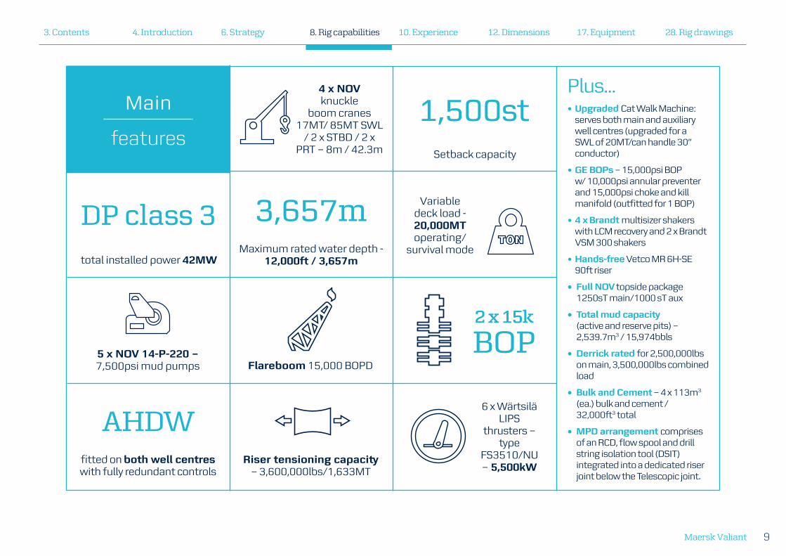
Rig capabilities
Uptime and efficiency are maximised through dual pipe handling. While one string is working in the main well centre, a second string of casing, drill pipe or bottomhole assembly in the auxiliary well centre can be both assembled and run back in the setback area for later use, assembled and ran in the auxiliary well centre, or disassembled and laid out on the deck.
Dual mud systems ensure efficient change between mud types and completion fluids. The travelling system; crown sheaves, travelling block and main well centre top drive are rated for 1,250MT, enabling a total drilling depth of up to 40,000ft/12,000m.
The Maersk Valiant also has substantial accommodations for 230 people and considerable storage and tank capacities for long-range and extended operational capabilities.
The Maersk Valiant is a Samsung 96K designed drillship with several Maersk Drilling upgrades including Managed Pressure Drilling (MPD).
The design and capacities of the drillship includes features for high-efficiency operation. Featuring dual derrick and large subsea work and storage areas, the design allows for efficient well construction and field development activities through parallel and offline activities.
4. Introduction3. Contents 6. Strategy 12. Dimensions8. Rig capabilities 10. Experience 17. Equipment 28. Rig drawings
Maersk Valiant 9
6 x Wärtsilä LIPS
thrusters – type
FS3510/NU – 5,500kW
4 x NOV knuckle
boom cranes 17MT/ 85MT SWL
/ 2 x STBD / 2 x PRT – 8m / 42.3m
Maximum rated water depth - 12,000ft / 3,657m
3,657m
Setback capacity
total installed power 42MW
fitted on both well centres with fully redundant controls
1,500st
DP class 3
AHDW
Variable deck load - 20,000MT operating/
survival mode
5 x NOV 14-P-220 – 7,500psi mud pumps
Plus...• Upgraded Cat Walk Machine:
serves both main and auxiliary well centres (upgraded for a SWL of 20MT/can handle 30” conductor)
• GE BOPs – 15,000psi BOP w/ 10,000psi annular preventer and 15,000psi choke and kill manifold (outfitted for 1 BOP)
• 4 x Brandt multisizer shakers with LCM recovery and 2 x Brandt VSM 300 shakers
• Hands-free Vetco MR 6H-SE 90ft riser
• Full NOV topside package 1250sT main/1000 sT aux
• Total mud capacity (active and reserve pits) – 2,539.7m3 / 15,974bbls
• Derrick rated for 2,500,000lbs on main, 3,500,000lbs combined load
• Bulk and Cement – 4 x 113m3 (ea.) bulk and cement / 32,000ft3 total
• MPD arrangement comprises of an RCD, flow spool and drill string isolation tool (DSIT) integrated into a dedicated riser joint below the Telescopic joint.
Main
features
Flareboom 15,000 BOPD
Riser tensioning capacity – 3,600,000lbs/1,633MT
2 x 15k
BOP
4. Introduction3. Contents 6. Strategy 12. Dimensions8. Rig capabilities 10. Experience 17. Equipment 28. Rig drawings

Maersk Valiant10
Experience Drilling successfully with a customised MPD systemManaged pressure drilling (MPD) has been lacking in the US Gulf of Mexico for a long period. The Maersk Valiant presented an opportunity for ConocoPhillips and Marathon Oil to bring a state-of-the-art seventh-generation drillship into the Gulf with an MPD system. The system needed to handle high and low flow rates, large cuttings and a high cuttings
volume, and measure flow more accurately. Rather than just counting pump strokes, our customers wanted flow meters on all pumps, and to be able to feed this data into their hydraulics model. Maersk Drilling and the Maersk Valiant crew successfully drilled two challenging wells using this customised MPD system.
Driving Energy Efficiency to reduce costs and CO2 emissionsThe Maersk Valiant engaged in an energy-efficiency project using an Energy Management System (MSPS) to capture real-time consumption on-board. By analysing fuel consumption, Maersk Drilling delivered fuel cost savings to our customers and reduced the CO
2 emissions,
by reducing energy consumption during actual operation. Specific initiatives were to reduce the number of engines running at low loads, and to reduce hotel consumption by installing variable frequency drivers on lube and cooling water pumps.
4. Introduction3. Contents 6. Strategy 12. Dimensions8. Rig capabilities 10. Experience 17. Equipment 28. Rig drawings
Maersk Valiant 11
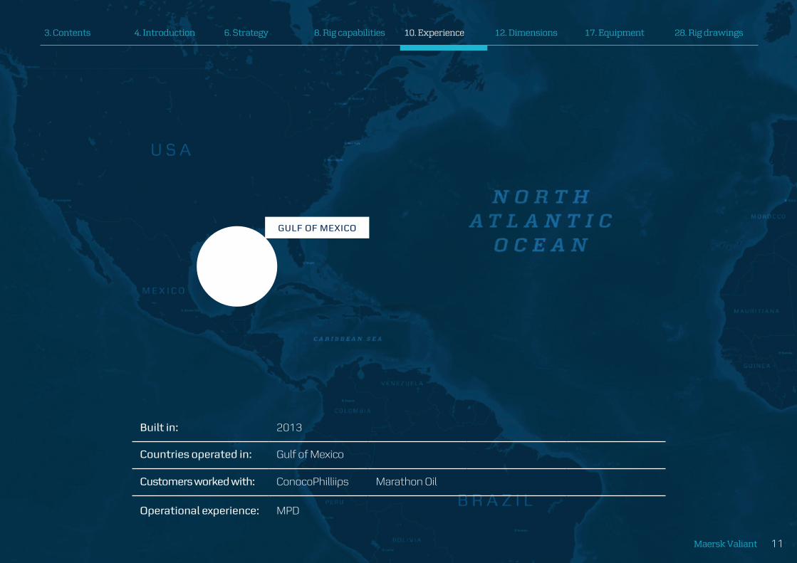
GULF OF MEXICO
Built in: 2013
Countries operated in: Gulf of Mexico
Customers worked with: ConocoPhilliips Marathon Oil
Operational experience: MPD
4. Introduction3. Contents 6. Strategy 12. Dimensions8. Rig capabilities 10. Experience 17. Equipment 28. Rig drawings
Maersk Valiant12
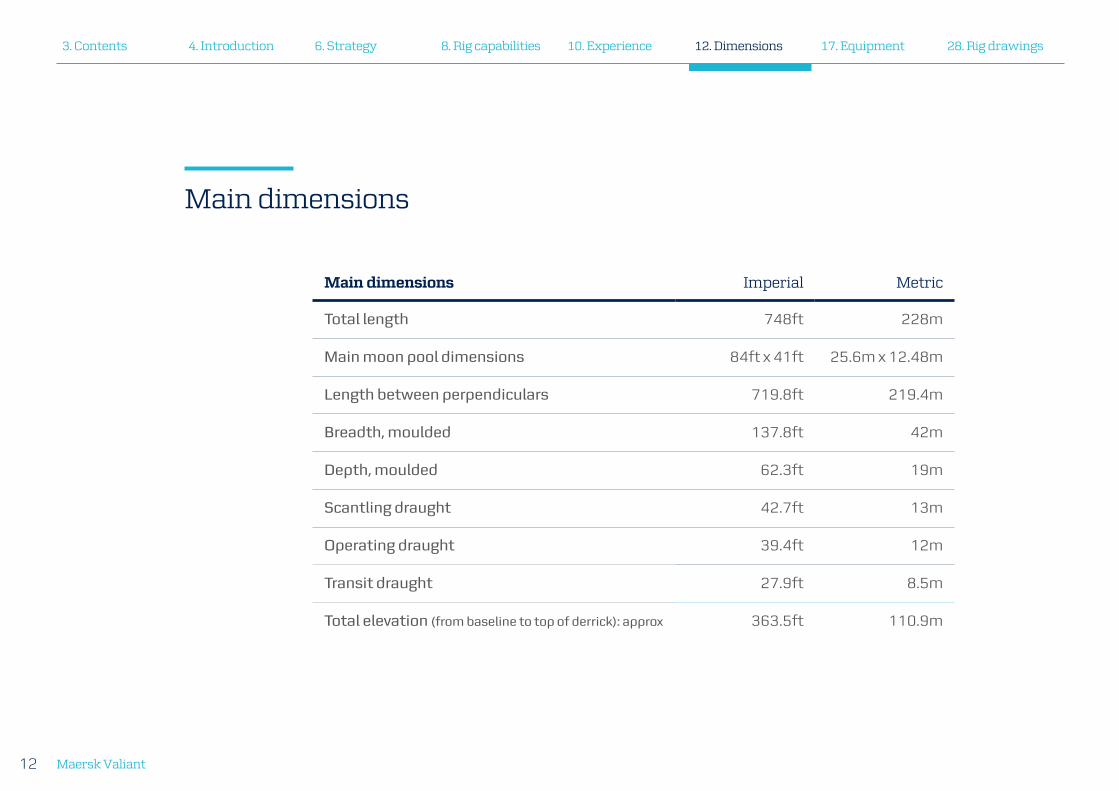
Main dimensions Imperial Metric
Total length 748ft 228m
Main moon pool dimensions 84ft x 41ft 25.6m x 12.48m
Length between perpendiculars 719.8ft 219.4m
Breadth, moulded 137.8ft 42m
Depth, moulded 62.3ft 19m
Scantling draught 42.7ft 13m
Operating draught 39.4ft 12m
Transit draught 27.9ft 8.5m
Total elevation (from baseline to top of derrick): approx 363.5ft 110.9m
Main dimensions
4. Introduction3. Contents 6. Strategy 12. Dimensions8. Rig capabilities 10. Experience 17. Equipment 28. Rig drawings

Maersk Valiant 13
Operational capabilities Imperial Metric
Drilling depth 40,000ft 12,000m
Drilling water depth 12,000ft 3,658m
Riser tensioner load 3,600,000lbs 1,633MT
Variable load capacity Imperial Metric
Transit mode 36,376,300lbs 16,500MT
Drilling mode 44,092,500lbs 20,000MT
Survival mode 44,092,500lbs 20,000MT
Maximum design limits
4. Introduction3. Contents 6. Strategy 12. Dimensions8. Rig capabilities 10. Experience 17. Equipment 28. Rig drawings

Maersk Valiant14
Environmental design limits
Design DP operating condition Imperial Metric
Sign. wave height (max) 19ft 5.8m
Wave period (max) 10.6 sec 10.6 sec
Wind speed (max) 50 knots 26m/s
Current velocity (max) 2.5 knots 1.3m/s
Survival/Transit condition Imperial Metric
Sign. wave height (max) 47ft 14.4m
Wave period (max) 17 sec 17 sec
Wind speed (max) 100 knots 51m/s
4. Introduction3. Contents 6. Strategy 12. Dimensions8. Rig capabilities 10. Experience 17. Equipment 28. Rig drawings

Maersk Valiant 15
Design DP operating condition Imperial Metric
Max. heave 10ft 3.0m
Max. pitch 3.2 deg 3.2 deg
Max. roll 2.0 deg 2.0 deg
4. Introduction3. Contents 6. Strategy 12. Dimensions8. Rig capabilities 10. Experience 17. Equipment 28. Rig drawings

Maersk Valiant16
Storage capabilities Imperial Metric
Drill water 15,158bbls 2,410m³
Potable water 8,963bbls 1,425m³
Fuel oil 39,060bbls 6,210m³
Brine 4,887bbls 777m³
Base oil 6,277bbls 998m³
Liquid mud (active) 5,678bbls 902.7m³
Liquid mud (reserve) 10,296bbls 1,637m³
Bulk mud 15,962ft³ 452m³
Bulk cement 15,962ft³ 452m³
Waste mud (slop tank) 1,622bbls 258m³
Storage capabilities
4. Introduction3. Contents 6. Strategy 12. Dimensions8. Rig capabilities 10. Experience 17. Equipment 28. Rig drawings

Maersk Valiant 17
Accommodation
With comfortable living areas and the ability to host high numbers of service company personnel, the Maersk Valiant’s accommodation offers more than just bed space. Large common office space enables good cooperation between Maersk Drilling, operator and service company personnel with several dedicated rooms for meetings.
Equipment
Total beds: 230
• 10 x single-berth cabins with private toilet
• 110 x twin-berth cabins with private toilet
2 x company representative offices, with 2 desks each
1 x open office with 20 desks shared with Maersk Drilling
1 x open office with 10 desks
1 x conference room seating 14
2 x conference rooms seating 10 people each, which can be joined to form one common room
1 x recreation room for non-smokers: 28 seats
1 x recreation room for smokers: 28 seats
1 x library/quiet room: 17 seats
1 x IT cafe with 8 seats
1 x gym
1 x games room
Main mess seating: 102
Catering mess seating: 8
4. Introduction3. Contents 6. Strategy 12. Dimensions8. Rig capabilities 10. Experience 17. Equipment 28. Rig drawings

Maersk Valiant18
Deck cranes / handling systems
In addition to the four main hydraulic knuckle boom deck cranes, a dedicated pipe handling crane covers the drill pipe and casing storage deck areas. A gantry crane will cover the riser bays and slip joint to ensure safe and efficient handling. Both the BOP and subsea trees are handled by dedicated, guided gantry cranes and carriers.
4 x NOV knuckle boom cranes, 17MT/85MT SWL/2 x starboard /2 x port - 8m/42.3m. Two for starboard side and two port side placed forward and aft.
1 x NOV knuckle boom pipehandler w/ gripper yoke, 3.5MT/7,700lbs SWL, 3.2m/22.3m
540MT BOP gantry crane with full guiding system
230MT Xmas tree transport – head room for 13m high Xmas trees
150MT Xmas tree gantry crane c/w fully integrated guidance system
3 x forklifts, two of 1.5MT SWL and one of 2.5MT SWL
Dedicated runways arranged for forklift operation on vessel upper deck, topside main deck and sack storage area
4. Introduction3. Contents 6. Strategy 12. Dimensions8. Rig capabilities 10. Experience 17. Equipment 28. Rig drawings

Maersk Valiant 19
4. Introduction3. Contents 6. Strategy 12. Dimensions8. Rig capabilities 10. Experience 17. Equipment 28. Rig drawings

Maersk Valiant20
Drilling equipment
With a full NOV topside package, the Maersk Valiant is equipped to drill the most demanding wells in the world. Utilising Multi Machine Control (MMC) on the drill floor, this large degree of automation ensures safe operation, a reduction in equipment damage, and more importantly consistent performance. Within the derrick setback area, range 2 drill pipe can be racked back in quads or range 3 drill pipe in triples up to 135ft length. Casing of up to 16” diameter can be racked back in triples. Over 50,000ft of drill pipe can be racked including a heavy duty drill pipe landing strings.
Full NOV topside package 1,250MT main/1,000MT aux
NOV TDX1,250 on both well centres
RST 755 on main well centre, RST 605 on aux
Setback capacity – 1,500MT
Derrick rated for 2,500,000lbs on main, 3,500,000lbs combined load
• Hook/Rotary Load – Main – 1,250MT
• Hook/Rotary Load – aux – 453MT
NOV ARN 200 iron roughnecks x 2 – MU 140,000nm / 103,000ft-lbs, BO 200,000nm / 147,000ft-lbs
AHDW fitted on both well centres with fully redundant controls – dedicated separate cabinets for switchboards
• Power plant prepared for energy storage backup system, eliminating possibility of a black ship or loss of power to the DC bus
• Fast start recovery with power back to AHDW within 30 seconds
Advanced drill line monitoring system to enhance life and extend duration between slip and cut
15 MMscfd MGS with 12” vent line
2 x NOV HR-IV-ER Hydrarackers w/ Multi Machine Control
Upgraded cat walk machine: serves both main and auxiliary well centres
• Upgraded for a SWL of 20MT/ can handle 30” conductor
4. Introduction3. Contents 6. Strategy 12. Dimensions8. Rig capabilities 10. Experience 17. Equipment 28. Rig drawings

Maersk Valiant 21
Racking capacity:
• 16” casing – 24 stands x 126ft
• 7” to 14” casing – 64 stands x 126ft
• 7” to 10” casing – 4 5 stands x 126ft
• 57/8” DP to 65/8” DP – 196 stands x 133ft
• 5” DP – 90 stands x 133ft
• 3½” DP – 54 stands x 133ft
• 65/8” HWDP / CSG-LS – 104 stands x 124ft
• 8¼”DC – 7 stands x 124ft
• 9½” DC – 10 stands
• 9½” BHA – 4 stands in designated BHA Fingers
4. Introduction3. Contents 6. Strategy 12. Dimensions8. Rig capabilities 10. Experience 17. Equipment 28. Rig drawings

Maersk Valiant22
Marine / power
The Maersk Valiant is designed with a DP-3 Dynamic Positioning System, which is the highest for MODU operations. Additional built-in redundancy in critical systems allows for normal maintenance. The updated power management system has the most efficient black-out recovery configuration available today. This will ensure greatly enhanced overall safety.
DP Class 3 – total installed power 42MW
6 x Wärtsilä LIPS Thrusters – Type FS3510/NU – 5,500kW
Kongsberg Maritime/K-POS 32 and K-POS 12
DGPS – DPS 5D, DPS 232 and DPS 132
4 x fully equipped HIPAP 501 systems installed
3 x motion reference units (MRU 5) and 1 MRU5+ backup included in DGPS 5D
3 x gyro compasses, 5 x sets wind sensors
6 x Doosan / MAN 16V32/ 40 Engines – 7,248kW
6 x ABB, AMG 0900MR10LSE main generators – 7,000kW / 7,777kVA
1 x STX / Cummins – QSK60DMGE emergency engine – 1,900kW
1 x Newage / PM734E1 emergency generator – 1,350kW / 1,687.5kVA
6 x Noreq motorised fully enclosed (80 person) lifeboat / survival capsule
4. Introduction3. Contents 6. Strategy 12. Dimensions8. Rig capabilities 10. Experience 17. Equipment 28. Rig drawings
Maersk Valiant 23
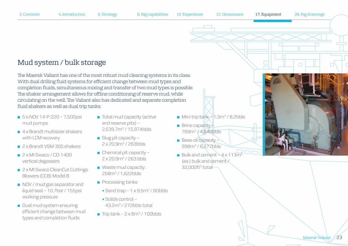
Mud system / bulk storage
The Maersk Valiant has one of the most robust mud cleaning systems in its class. With dual drilling fluid systems for efficient change between mud types and completion fluids, simultaneous mixing and transfer of two mud types is possible. The shaker arrangement allows for offline conditioning of reserve mud, while circulating on the well. The Valiant also has dedicated and separate completion fluid shakers as well as dual trip tanks.
5 x NOV 14-P-220 – 7,500psi mud pumps
4 x Brandt multisizer shakers with LCM recovery
2 x Brandt VSM 300 shakers
2 x MI Swaco / CD-1400 vertical degassers
2 x MI Swaco CleanCut Cuttings Blowers (CCB) Model B
NOV / mud gas separator and liquid seal – 10.7bar / 155psi working pressure
Dual mud system ensuring efficient change between mud types and completion fluids
Total mud capacity (active and reserve pits) – 2,539.7m3 / 15,974bbls
Slug pit capacity – 2 x 20.9m3 / 263bbls
Chemical pit capacity – 2 x 20.9m3 / 263 bbls
Waste mud capacity: 258m3 / 1,622bbls
Processing tanks
• Sand trap – 1 x 9.5m3 / 60bbls
• Solids control – 43.2m3 / 272bbls total
Trip tank – 2 x 8m3 / 100bbls
Mini trip tank – 1.3m3 / 8.2bbls
Brine capacity – 769m3 / 4,840bbls
Base oil capacity – 998m3 / 6,277bbls
Bulk and cement – 4 x 113m3 (ea.) bulk and cement / 32,000ft3 total
4. Introduction3. Contents 6. Strategy 12. Dimensions8. Rig capabilities 10. Experience 17. Equipment 28. Rig drawings
Maersk Valiant24
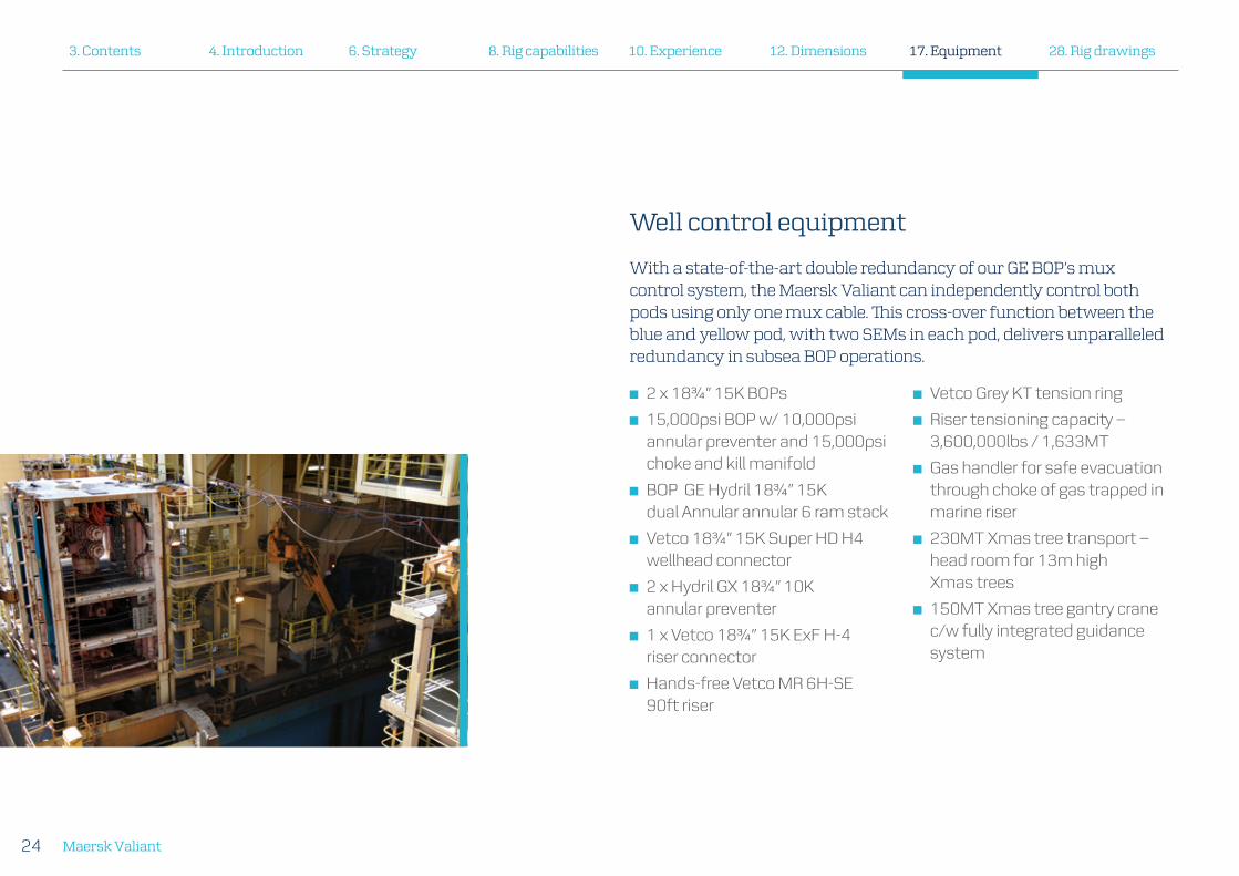
Well control equipment
With a state-of-the-art double redundancy of our GE BOP’s mux control system, the Maersk Valiant can independently control both pods using only one mux cable. This cross-over function between the blue and yellow pod, with two SEMs in each pod, delivers unparalleled redundancy in subsea BOP operations.
2 x 183/4” 15K BOPs
15,000psi BOP w/ 10,000psi annular preventer and 15,000psi choke and kill manifold
BOP GE Hydril 183/4” 15K dual Annular annular 6 ram stack
Vetco 183/4” 15K Super HD H4 wellhead connector
2 x Hydril GX 183/4” 10K annular preventer
1 x Vetco 183/4” 15K ExF H-4 riser connector
Hands-free Vetco MR 6H-SE 90ft riser
Vetco Grey KT tension ring
Riser tensioning capacity – 3,600,000lbs / 1,633MT
Gas handler for safe evacuation through choke of gas trapped in marine riser
230MT Xmas tree transport – head room for 13m high Xmas trees
150MT Xmas tree gantry crane c/w fully integrated guidance system
4. Introduction3. Contents 6. Strategy 12. Dimensions8. Rig capabilities 10. Experience 17. Equipment 28. Rig drawings
Maersk Valiant 25
4. Introduction3. Contents 6. Strategy 12. Dimensions8. Rig capabilities 10. Experience 17. Equipment 28. Rig drawings
Maersk Valiant26
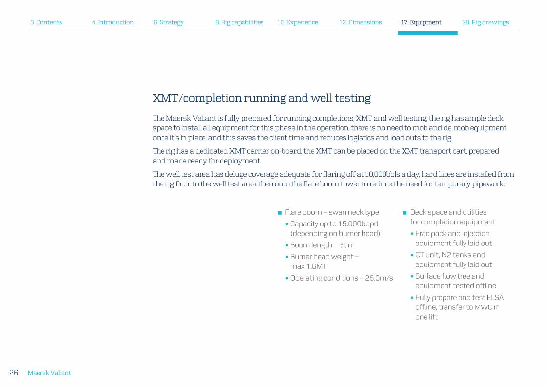
XMT/completion running and well testing
The Maersk Valiant is fully prepared for running completions, XMT and well testing, the rig has ample deck space to install all equipment for this phase in the operation, there is no need to mob and de-mob equipment once it’s in place, and this saves the client time and reduces logistics and load outs to the rig.
The rig has a dedicated XMT carrier on-board, the XMT can be placed on the XMT transport cart, prepared and made ready for deployment.
The well test area has deluge coverage adequate for flaring off at 10,000bbls a day, hard lines are installed from the rig floor to the well test area then onto the flare boom tower to reduce the need for temporary pipework.
Flare boom – swan neck type
• Capacity up to 15,000bopd (depending on burner head)
• Boom length – 30m
• Burner head weight – max 1.6MT
• Operating conditions – 26.0m/s
Deck space and utilities for completion equipment
• Frac pack and injection equipment fully laid out
• CT unit, N2 tanks and equipment fully laid out
• Surface flow tree and equipment tested offline
• Fully prepare and test ELSA offline, transfer to MWC in one lift
4. Introduction3. Contents 6. Strategy 12. Dimensions8. Rig capabilities 10. Experience 17. Equipment 28. Rig drawings

Maersk Valiant 27
Managed Pressure Drilling (MPD)
The Maersk Valiant’s Surface Backpressure (SBP) Managed Pressure Drilling (MPD) system is a closed-loop pressurised circulating drilling fluid system, where bottomhole pressure can be adjusted by choking the drilling fluid return at MPD choke manifold. The system may be used for Constant Bottomhole Pressure (CBHP) drilling, Pressurised Mudcap (PMCD) drilling, and controlled pressure while cementing.
BTR-SI 7875 Rotating Control Device (RCD) by Weatherford
Drill String Isolation Tool (DSIT) to isolate RCD and act as Riser Gas Handler (RGH) – uses standard Shaffer style 21¼” 2k packing element and seal kit
AF Global Flowspool joint:
• Mud return is arranged via the flow spool to rig topside MPD equipment package which comprise of buffer manifold, MPD choke manifold, flowmeters manifold and control system
• SafeKick Intelli-Choke™ MPD Manifold:
– SafeKick data acquisition and choke control system provides an automated control of downhole pressures
• Real-time Transient Hydraulic Modeling
• 8” pipework and a combination of 2 x 3” and 2 x 6” Electric Servo Actuated Chokes, allows MPD system to be utilised for multiple flow regimes
• 2 x 8” Flow out Coriolis Meters
• In addition, high-precision Coriolis Meters installed downstream all 5 pre-charge pumps (at Mud Pumps) to measure real-time flow – in mass and volume
Integrated Riser Joint Operator’s Panel
HMI – Driller’s Operator Panel/Valve Control Panel
• 2 x Pressure Relief Valves (PRV) Control Panels
• Electric Actuated and Manual Ball Valves
• High Resolution Pressure Transducers
Early Kick Detection (EKD) uses Coriolis meters to measure the mass flow in and out of drilling fluid during the drilling process to provide advanced kick detection
4. Introduction3. Contents 6. Strategy 12. Dimensions8. Rig capabilities 10. Experience 17. Equipment 28. Rig drawings

Maersk Valiant28
MOONPOOL
BALLASTPUMP ROOM
DRAI
N HO
LDIN
G T
.(P&S
)
CENT
. STE
RN T
HRUS
TER
ROO
M
ENGINE ROOM(C,P&S)
VOID(C)
NO.2 HOLD
B.T
.(P&S
)
BASE OIL T.(P)
CABLE TRUNK(P&S)
FWD. AUX. MACH. R
M(C)
NO.1 F.W
.T.(P&S)
CEN
TER
BO
W T
HR
UST
ER R
M
ACCOMMODATION SPACE
SWBD ROOM(C,P&S)
ENGINE WORKSHOP
ELEC. WORKSHOP
& STORE
NO.1 FWD D/B W.B.T.(C)
E.C.R(C)
PORT & STBDSTERNTHRUSTER RM
SECONDARY ESC WAY (P&S)
NO.6 W.B.T. (P&S)
ROPE
STORE(P)
PURIFIERROOM(P&S)
NO.2 HOLD
B.T.
(C)
PORT
& ST
BD B
OW T
HRUSTER
RM
3RD DECK (10.500m A/B)
2ND DECK (14.580m A/B)
NO.4 W.B.T.(P&S)
NO.5 HOLD B.T.(P&S)
H.P
.R. C
OM
P'T
(P&S
)
H.P
.R. C
OM
P'T
(P&S
)
NO.3. W.B.T.(P
&S)
NO.3. HOLD B.T(P&S)
NO.2. W.B.T.(P&S)
NO.4. HOLD B.T.(P
&S)
BOSUNSTORE C.L.
NO.2 F.W
.T.(S)
A.P.T
.(P&S)
DRILLING W.T.(P
&S)
VOID
B.W.EXH.AIRSPACE
VOID
VOID
AIR COND. UNIT ROOM(C)
STAIRWAY
S/C(P
&S)
NO.1
HO
LD B
.T.(C
)
NO.1 AFT W.B.T. (P&S)
NO.1 HOLD B.T.(S)
NO. 3,4
RESERVE
PIT.T.(S)
DRY BULK T.(C)
NO.1 BRIN
E
T.(P)
WASTE
MUD T.(S)
NO. 1.2
RESERVE
PIT.T.(S)
AGITATOR
SPACE(S)
NO.1 HOLD B.T.(P)
NO.2,3 B
RINE
T.(P)14.500 m A/B
8.100 m A/B7.300 m A/B
12.900 m A/B
NO.1
D.O
.STO
R. T
.(P&S
)
NO.5 W.B.T.(P
&S)
NO
.2 D
.O.S
TOR
. T.(P
&S)
D.O
. SER
V. T
.(P&S
)
C/D
SEP.BILGEOIL T. PURIFIER SLUDGE
T.(P&S)BILGEHOLD. T.
S/C(P&S)
B/W
L.O.S
TOR.T.
L.O.SETT.T.
EM'C
Y EXIT(P&S)
11.600m A/B
NO.6 RESERVE
PIT. T.(P
)
NO.2 F.W.T.(P)
TRANS-FORMERSPACE
12.900m A/B
VOID
D.O. OVERFLOW
DRAIN T.(P&S)
SECONDARY ESC. WAY FWD (P&S)
C/DC/D
C/D
C/D
UP
EXH.VENT
BURNER BOOMPEDESTAL
OXY.RM
ACERM
PAINTSTORE
WATER MIST& INERGENROOM
HYD. POWERPACK ROOM
INCIN. RM
FRESH AIRINTAKE TRUNKVENT FOR AIRCOND.
LIFTINGSPACE
MESS ROOM
C.G.L.
0 10 20 30 40 50 60 65 70 75 80 85 90 95 100 105 110 120 130 140 150С.L.
160
UP
UP UP
C.G.L
CREW(2P)
AIRRETURN
CREW(2P) CREW(2P) CREW(2P) CREW(2P)CREW(2P)
CREW(2P)
CREW(2P)
CREW(2P)
CREW(2P)
CREW(2P)
CREW(2P)CREW(2P)
CREW(2P)CREW(2P)
CREW(2P) CREW(2P)
CREW(2P) CREW(2P)
CREW(2P) CREW(2P) CREW(2P)
CREW(2P)
CREW(2P)CREW(2P)CREW(2P)CREW(2P)CREW(2P)CREW(2P)
EL.TRUNK
EL.TRUNK
PIPESPACE
AIRRETURN
UP
DN
DN UP
LIFT
UP
DN
AU
X.M
AC
H.
RM
.HA
TCH
PIPESPACE
AIRRETURNUP
DN
CREW(2P) CREW(2P) CREW(2P) CREW(2P) CREW(2P)CREW(2P)
CREW(2P)
CREW(2P)
CREW(2P)
CREW(2P)
CREW(2P)CREW(2P)
CREW(2P)
CREW(2P) CREW(2P) CREW(2P)
CREW(2P)CREW(2P)CREW(2P)
CREW(2P) CREW(2P) CREW(2P)
CREW(2P)
CREW(2P)CREW(2P)CREW(2P)CREW(2P)CREW(2P)CREW(2P)
DN UP
LIFT
EL.TRUNK
EL.TRUNK
AIRRETURN
LINEN LOCKER
LINEN LOCKER
UP
DN
NAVIGATIONINSTRUMENT
ROOM
DP BACK-UPROOM
COMMON OFFICE
CONFERENCE ROOM-1
CABELTRUNK
CREW(2P) CREW(2P) CREW(1P)CREW(1P)
CREW(1P)
CREW(1P)
CREW(1P)
CREW(1P)
CREW(1P)
CREW(1P)
CREW(1P)
CREW(1P)
DOCUMENT ROOM
CONFERENCE ROOM-2
CONFERENCE ROOM-3
CGL
UP
DN
UP
DN
EL.TRUNK
EL.TRUNK
LOBBY
DN UP
PIPESPACE
AIRRETURN
LIFT
LOC
KE
R
LOC
KE
R
AIRSUPPLY
OFFICERSCHANGING
ROOM
OIM OFFICE
BA
RG
E E
NG
./A
SS
. BA
RG
EE
NG
.OFFIC
E
MAINTENANCE/
ASS. MAIN ENG. OFFICE
SE
N. TO
OL P
US
HE
R/
TOO
L PU
SH
ER
OFFIC
E
MAERSKOFFICE
CLIENTOFFICE
OPEN OFFICE
WHEELHOUSE(INCL. CHART &RADIO SPACE)
CLIENTOFFICE
PIPE & EL.TRUNK
EL.TRUNK
DN UP
DN
UP
DN
UP
AIRSUPPLY
AIR
RE
TUR
N
PRINTERROOM
LIFT
AU
X.M
AC
H.
RM
.HA
TCH
DN
DN
DN
UP
VENT.(SUP)
VENT.
VOID
AHU ROOM
AHU ROOM
LANDINGSPACE
GENERALSTORE
VOID
LIFTINGSPACE
FRESH AIRINTAKE VENT
NO.1HOLD B. TK (C)
AUX.MACH.RM. EXH.VENT
DOME
C.F.W.EXP.TK
LIFTINGSPACE
ELECTRICSPACE
NO
.2 THR
US
TER
RO
OM
SECONDARYESCAPE WAY(P)
AHU ROOM
DN
VENT
SECONDARYESCAPE WAY(S)
VOID
NO
.1 THR
US
TER
RO
OM
NO
.3 THR
US
TER
RO
OM
RETURNTRUNK
UPDN
UP
UP DN
UP
UP
UP
SUPPLYTRUNK
UP
DN
VENT
UP
DNDN
VENT
CREW(2P) CREW(2P) CREW(2P) CREW(2P) CREW(2P)CREW(2P)
CREW(2P)
CREW(2P)CREW(2P) CREW(2P)
CREW(2P)CREW(2P)CREW(2P)
CREW(2P) CREW(2P)
CREW(2P)CREW(2P)
CREW(2P) CREW(2P)
CREW(2P)
CREW(2P)
CREW(2P)
CREW(2P)
CREW(2P)CREW(2P)CREW(2P)CREW(2P)CREW(2P)CREW(2P)
AU
X.M
AC
H.
RM
.HA
TCH
EL.TRUNK
EL.TRUNK
LINEN LOCKER
PIPESPACE
AIRRETURN
DN UP
LIFT
C.G.L
C.G.LAIR
RETURN
DN
UP
DN
UP
DN
DN
OPENING FOR FRESHAIR INTAKE OF EM'CY
GEN. ROOM
SE
CO
ND
AR
YE
SC
. WA
Y
SE
CO
ND
AR
YE
SC
. WA
Y
NO.1 AFT W.B.T.(S) NO.1 AFT W.B.T.(P)
AGITATOR SPACE(S)
BASE OIL T.(P)
NO.1 HOLD B.T.(S) NO.1 HOLD B.T.(P)
NO.4 RESERVE
PIT T.(S)
NO.3 RESERVE
PIT T.(S)
DRY BU
LK T
.(C)
DR
AIN
HO
LDIN
GT.
(S)
SE
CO
ND
AR
YE
SC
. WA
Y
SE
CO
ND
AR
YE
SC
. WA
Y
NO.1 AFT W.B.T.(S) NO.1 AFT W.B.T.(P)
AGITATOR SPACE(S)
BASE OIL T.(P)
NO.1 HOLD B.T.(S) NO.1 HOLD B.T.(P)
NO.2 RESERVE
PIT T.(S)
NO.1 RESERVE
PIT T.(S)
DRY BU
LK T
.(C) S
EC
ON
DA
RY
ES
C. W
AY
SE
CO
ND
AR
YE
SC
. WA
Y
NO.1 AFT W.B.T.(S) NO.1 AFT W.B.T.(P)
AGITATOR SPACE(S)
NO.3 BRIN
E
T.(P)
NO.1 HOLD B.T.(S) NO.1 HOLD B.T.(P)
NO.5 RESERVE
PIT T.(S)
WASTE M
UD T.(S)
DRY BU
LK T
.(C)
NO.2 BRIN
E
T.(P)
VOID
GAME ROOM
CHANGING ROOM(MAN) VOID
NO
.1 THR
USTER
RO
OMLAUNDRY
PRAYERROOM
IRONINGROOM
LEAVELOCKER LINEN LOCKER
CHANGING ROOM(WOMEN)
UP
UPDN
GYMNASIUM
VOID
NO
.3 THR
US
TER
RO
OM
NO
.2 THR
US
TER
RO
OM
TELE.BO
OTH
W.C
EL.TRUNK
EL.TRUNK
LOCKER
NO.1HOLD B.T. (C)
SECONDARYESCAPE WAY(P)
SECONDARYESCAPE WAY(S)
FWD.AUX.MACH.RM.EXH.VENT
CLEAN COVERALLSTORE
PIPESPACE
AIRRETURN
VENT.(EXH.)
VENT.(SUP.)
VENT.(SUP.)
UPDN
UP
UPDN
C.G.L.
AIRSUPPLY
VENT
VENT
LIFTINGSPACE
UP DN
VENT.
VENT.(EXH.)
LIFT
DN
UP
LIFTINGSPACE
LIFTINGSPACE
UP
UP
EX
H. FO
RA
IR C
ON
D.
DN TO AHUROOM
LIFTINGSPACE
DRILLING W.T. (P)
AUX.MACHINERYROOM
DN
DN
DN
UP
UP
UP
3022C.L.
UP
UP
UP
UP
UP
UP
UP
UP
VENT
VENT
VENT
VENT
VENT
VENT
DN
DN
DN
DN
DN
DN
DN
DN
DN
C.L.3022
C.L.C.L.3022
C.L.C.L.
3022C.L.C.L.
3022C.L.C.L.
STR.1 PLAN STR.2 PLAN FUNNEL TOP PLAN
"B" DECK PLAN "C" DECK PLAN
NO.1HOLD B. T.(C)
NO.1AFT W.B.T. (P)
DRILLING W.T. (P)
VOID
DRILLING W.T. (S)
NO.1AFT W.B.T. (S)
NO.1F.W. T. (P)FWD. AUX
MACHINERYROOM
LIFTINGSPACE
VOID
NO.1F.W. T. (S)
VOID
VOID
DN
UP
UP
UP
UP
DNUP
UP
UP
UPUP
UP
DN
DN
DRILLING W.T. (S)
VOID
VOID
VOID
VOID
NO.1F.W.T. (P)
NO.1F.W.T. (S)
NO.1HOLD B.T. (C)
PORT BOWTHRUSTERROOM
STBD BOWTHRUSTERROOM
DN UP
DN
UP
NO.1AFT W.B.T. (P)
NO.1AFT W.B.T. (S)
UP
UP
DN
UPDN
UPDN
UP
PORTENG. RM
NO.2 M.D.O.STOR. T. (P)
M.D.O.SERV.T. (P)
BALLASTPUMP ROOM
NO.2 M.D.O.STOR. T. (S)
M.D.O.SERV.T. (S)
STBDENG. RM
CENT.ENG. RM
NO.6W.B. T. (P)
NO.6W.B. T. (S)
A.P. TK (S)
A.P. T. (P)
LANDINGAREA
LANDINGAREA
LANDINGAREA
NO.5 W.B. T. (S)
UP
UP
DN
DN
THRUSTER
THRUSTER
THRUSTER
DN
DN
UP
UP
UP
UP
NO.6 W.B. T. (P)
NO.2 M.D.O.STOR. TK (P)
BALLASTPUMP ROOM
NO.2 M.D.O.STOR. TK (S)
NO.6 W.B. T. (S)
VENT
CENT ENGINE RM
PORT ENGINE RM
STBD ENGINE RM
LIFTINGHATCH
PORT TRANS-FORMER SPACE
ELEC.WORKSHOP& STORE
ENG.WORKSHOP
CENT TRANS-FORMER SPACE
STBD STERNTHRUSTER RM
VENT
VENT
A.P. T. (S)
A.P. T. (P)
VENT
EM'CYEXIT
L.O. DRAINT. (P)
NO.2 F.W. T. (S) ENG. STORE
STBD TRANS-FORMER SPACE
VENT
EM'CYEXIT
EM'CYEXIT
VENT
L.O.DAILYT.
UPDN
UP
UP
UP
UP
UP
UP
DN
LIFTINGHATCH
UP
DN
UPD
N
NO.4 HOLD. B.TK.(S) NO.4 HOLD. B. TK.(P)
NO. 1 THRUSTER ROOM
EXH. TRUNKFOR LAUNDRY
DUCTTRUNK
DUCTTRUNK
ACCESS TRUNK FORNO. 1 THRUSTER ROOM
ACCESS TRUNKFOR BOSUN STROKE
SE
CO
ND
AR
YE
SC
. WA
Y
SE
CO
ND
AR
YE
SC
. WA
Y
W.B.T. (S) W.B.T. (P)
NO.5 HOLD B.T.(S) NO.5 HOLD B.T.(P)VOID(C)MOON POOL
W.B.T. (S) W.B.T. (P)
SE
CO
ND
AR
YE
SC
. WA
Y
SE
CO
ND
AR
YE
SC
. WA
Y
H.P.R.COMP.
H.P.R.COMP.
H.P.R.COMP.
H.P.R.COMP.
DRAINHOLDINGT.
CENT. STERNTHRUSTERROOM
EM'CY EXIT
EM'CY EXIT
EM'CY EXIT
STBD. STERNTHRUSTER RM
PORT STERNTHRUSTERROOM
ENGINE ROOM (P)
ENGINE ROOM (C)
ENGINE ROOM (S)
NO.6 W.B.T.(S
)
NO.6 W.B.T.(P
)NO.5 HOLD B.T.(P)
NO.5
W.B
.T.(P
)
NO.1 D
.O. S
TOR. T
.(P)
S/C
S/C
A.P.T.(S)
A.P.T.(P)
BILG
E H
OLD
. T.
PURIFIERROOM (S)
PURIFIERROOM (P)
PURIFIERSLUDGE T.(S)
PURIFIERSLUDGE T.(P)
SEP. BILGE
OIL.T.(C)
D.O
. SE
RV
.T(S
)D
.O. S
ER
V.T
(P)
BALLASTPUMP ROOM
DRAIN HOLDING
.T.(S)
DRAIN HOLDING
.T.(P)
NO.5
W.B
.T.(S
)
NO.1 D
.O. S
TOR. T
.(S)
NO.2
D.O
.ST
OR.
T.(S
)
NO
.2 D
.O.
STO
R. T
.(P)
MOONPOOL
VOID
NO.3 W.B. T
.(P)
NO.5 HOLD B.T.(S)
NO.4 W.B. T
.(S)
NO.4 W.B. T
.(P)
VOID(C)
NO.4 HOLD B.T.(P)
NO.3 HOLD B.T.(P)
NO.3 HOLD B.T.(S)
NO.4 HOLD B.T.(S)
NO.3 W. B.T.(S)
DRY BULK T.(C)
BASE OIL T.(P)NO.2 W.B. T.(P
)
NO.2 HOLD
B.T.(P
)
NO.2 HOLD B.T.(C)
NO.2 HOLD
B.T.(S
)NO.2 W. B
.T.(S)
NO.1 HOLD
B.T
.(C)
NO.1 AFT W.B.T.(P
)
NO.1 HOLD B.T.(P)
VOID
VOID
NO.1BRINET.(P)
NO.3BRINET.(P)
NO.2BRINET.(P)
NO.1RESERVEPIT T.(S)
NO.2RESERVEPIT T.(S)
NO.4RESERVEPIT T.(S)
NO.3RESERVEPIT T.(S)
WASTEMUD T.(S)
NO.1 AFT W.B.T.(S
)
PORTBOW THRUSTERROOM
STB'DBOW THRUSTERROOM
DRILLING W.T.(S)
DRILLING W.T.(P)VOID
VOID
BILG
EHO
LD T
.
FWD. AUX. M
ACH. RM.
NO.1 FW
DD/B
W.B
..T.(C
)
ECHO SOUNDEM LOGTRANSDUCER NO.1
F.W.T.(S
)
NO.1
F.W.T.(P
)
VOID
CENTERBOWTHRUSTERROOM
NO.5RESERVEPIT T.(S) NO.1 HOLD
B.T. (S)
0 10 20 30 40 50 60 65 70 75 80 85 90 95 100 105 110 120 130 140 150С.L.
160
B/W
B/W
B/W
NO.2
F.W.T.(S)
ROPE
STORE(P)
B/W
B/W
B/W
B/W
B/W
B/W S/C
S/C
NO.6RESERVEPIT T.(S)
S/CB/W
S/C
S/C
S/C
NO.2F.W.T.(P)
D.O.OVERFLOW/DRAIN T.(S)
D.O.OVERFLOW/DRAIN T.(P)
O/D
C/D
C/D
C/D
F'CLE DECK PLAN(B - DECK PLAN) HELI. DECK PLAN
NAV/BRI. DECK PLAN1ST DECK PLAN
2ND DECK PLAN
E - DECK PLAN
D - DECK PLAN
3RD DECK PLAN
FLOOR PLAN C - DECK PLAN
FR. 95 SECTION(LOOKING AFT)
FR. 97 SECTION(LOOKING AFT)
FR. 99 SECTION(LOOKING AFT)
MIDSHIP SECTION(LOOKING AFT)
TYPICAL SECTION(LOOKING AFT)
NO.5 W.B.T. (S)
NO.5 W.B.T. (P)
NO.1 M.D.O. STOR. TK (P)
NO.1 M.D.O. STOR. TK (S)
DRAIN HOLDING T.(P)
DRAIN HOLDING T.(S)
VOID(C)
NO.5 HOLDB.T. (S)
NO.5 HOLDB.T. (P)
NO.1 M.D.O. STOR. T. (P)
DRAIN HOLDING T.(P)
DRAIN HOLDING T.(S)
NO.1 M.D.O. STOR. T. (S)
VOID(C)
NO.5 W.B.T. (P)
NO.5HOLDB.T. (P)
NO.5HOLDB.T. (S)
NO.4W.B.T.(P)
NO.4W.B.T.(S)
3RD DECK PLAN
FLOOR PLAN
2ND DECK PLAN
TANK TOP PLAN
UPPER DECK PLAN
VOID (C)
DNUPEM'CY
EXIT (S)
DN
DN
UP
UPEM'CYEXIT (P)
EM'CYEXIT (C)
DN
UP
UP DN
VENT
VENT
DN
UP
DN
SECONDARY ESCAPE WAY (P)
SECONDARY ESCAPE WAY (S)
A.P. T. (S)
A.P. TK (P)
NO.2 F.W. T. (P)
NO.2 F.W. T. (S)L.O. SETT. T. (S) L.O. STOR. T. (S)
VENT AREA
PORT ENGINE RM
CENT ENGINE RM
STBD ENGINE RM
L.O. SETT. T. (P) L.O. STOR. T. (P)
STBD ENG. RM.NO.1 M/G/ENGINE
STBD ENG. RM.NO.2 M/G/ENGINE
ENGINECONTROLROOMLI
FTIN
GSP
ACE
HATC
H
CENT MSBD RM
BALLASTPUMPROOM
PORT MSBD RM
STBD MSBD RM
NO.2 M.D.O.STOR. TK (S)
NO.2 M.D.O.STOR. T. (P) NO.1 M.D.O. STOR. T. (P)
DRAIN HOLDING T. (P)
DRAIN HOLDING T. (S)
NO.1 M.D.O. STOR. T. (S) NO.5 HOLDB. T. (S)
NO.5 HOLDB. T. (P)
CENT STERNTHRUSTER RM
STBD STERNTHRUSTER RM
ROPE STORE
LIFTINGSPACE
LIFTINGSPACE
E/R
CR
AN
E
E/R
CR
AN
E
E/R
CR
AN
E
DN
DN DN
UP
UP
DN
DN
UP
DN
DN
UP
DNDN
LOBBY
DNDN
UP
DN
UPUP
UP
PORT STERNTHRUSTER RM
UPUP
DN DN
DN
DN
UP
UP UP
UPUP
36.0 m A/B PLAN
NO.5 HOLD B.T.(P)
NO.5 HOLD B.T.(S)
VOID
NO.3 HOLD B.T.(P)
NO.4 HOLD B.T.(S)
NO.2 HOLD B.T.(P)
NO.3 HOLD B.T.(S)NO.2 HOLD B.T.(S)
BASE OIL T. (P)NO.4 HOLD B.T.(P)
NO.2
HO
LD B
.T.(C
)
DRAIN HOLDING
T (S)
DRAIN HOLDING
T (P)
NO.1 D.O
. STO
R. T.(P
)
NO.1 D.O
. STO
R. T.(S
)
SWBDROOM(S)
SWBDROOM(P)
SWBDROOM(C)
BALLASTPUMP ROOM
NO
.2 D
.O.
STO
R. T
.(P)
NO
.2 D
.O.
STO
R. T
.(S)
NO.1HOLD B.T.(P)
NO.1BRINET.(P)
NO.3BRINET.(P)
NO.2BRINET.(P)
PORT BOWTHRUSTER RM.
CABLE TRUNK(P)
CABLE TRUNK(S)STBD BOWTHRUSTER RM.
AGITATOR SPACE(S)
A.P.T. (S)
SECONDARY ESC. WAY FWD (S)
SECONDARY ESC. WAY FWD (P)SECONDARY ESCAPE WAY (P)
SECONDARY ESCAPE WAY (S)
DN
DN
DN
DN
DN
UP
DN
DN
UP
NO.1 H
OLD B
.T.(C
)
UP
DN
DN
DN
UP
DN
ACC. LADDER
ACC. LADDER
UP
MOON POOL
EM'CY GENERATORROOM
PIPESPACE
GALLEY
MEAT ROOM VEGETABLE ROOM
DAIRY
LOBBY
FISHROOM
SLOPCHEST
EL. TRUNK
DRY PROVISIONSTORE
AUX. MACH.EXH. VENT
FIRE CONTROLSTATION
LIFT &STAIRWAY
DNUP
EL. TRUNK
SC
ULL
ER
YAIR
INTA
KE
TRU
NK
FO
RM
AC
H. R
OO
M
AIRRETURN
CA
MP
BO
SS
OFF
ICE
CATERINGMESS ROOM
GARBAGESTORE
LIFT LOBBY
NO
.1 T
HR
US
TER
RO
OM
UP
DN
UP
NO
.1 T
HR
US
TER
RO
OM
PIPESPACE
EL. TRUNK
AUX. MACH.EXH. VENT
BOSUN STORE
UP DN
UP
DN
UP
DN
AIR
INTA
KE
TRU
NK
FOR
MA
CH
. RO
OM
FRE
SH
AIR
INTA
KE
FOR
GA
LLEY
LIBRARY
OPENINGFOR FRESH AIR
INTAKE OF EM'GYGEN. ROOM
RECREATION ROOM(SMOKER)
RECREATION ROOM(NON SMOKER)
IT CAFE
AIRRETURN
TREATMENTROOM
HOSPITAL LINERLOCKER
GENERAL ELECTRICROOM
FRE
SH
AIR
TRU
NK
FOR
GA
LLEY
CREW(2P) CREW(2P)
CREW(2P) CREW(2P)
CREW(2P) CREW(2P)
CREW(2P) CREW(2P)
CREW(2P) CREW(2P)
CREW(2P) CREW(2P)
CREW(2P) CREW(2P)
CREW(2P)
CREW(2P)
CREW(2P)
CREW(2P)
CREW(2P)
CREW(2P)
CREW(2P)
EL. TRUNK
AIRRETURN
C.G.L
LOBBY
LIFT
UP UP
23.0 m A/B PLAN(A - DECK PLAN)
PROFILE
B.O.P.AREA
30.0 m A/B PLAN
UP
UP
UPDN
VENT UP
UP
DN
DN
UP
DN
UP
DN
UP
UP
UP
UP
UP
UP
UP
UP
UP
UP
DN
UP
A.P. 6 10 16 20 24 31 34 41 45 49 55 61 64 65 66 6713 27 37 52 582
A.P. 6 10 16 20 24 31 34 41 45 49 55 61 64 65 66 6713 27 37 52 582
A.P. 6 10 16 20 24 31 34 41 45 49 55 61 64 65 66 6713 27 37 52 582 0 10 20 30 40 50 60 65 70 75 80 85 90 95 100 105 110 120 130 140 150С.L.
160
106 110 120 130 140С.L. С.L.
106 110 120 130 140С.L. С.L.
106 110 120 130 140С.L. С.L.
106 110 120 130 140С.L. С.L.
106 110 120 130 140 150
С.L.
160102
106 110 120 130 140 150
С.L.
160102
106 110 120 130 140 150
С.L.
160102
106 110 120 130 140 150
С.L.
160102
55 60 64 65 70 75 80 85 90 95 100 105 110С.L.
75 80 85 90 95 100 105С.L.
S.L.W.L. S.L.W.L.S.L.W.L. S.L.W.L. S.L.W.L. S.L.W.L.
S.L.W.L. S.L.W.L.S.L.W.L. S.L.W.L.
S.L.W.L. S.L.W.L.
8.8 m 8.8 m 27.2 m 4.8 m 9.6 m 28.8 m 22.4 m 35.2 m 25.6 m 12.8 m 21.6 m 12.2m 8.370m
(147.2 m)(112.0 m)(89.6 m)(60.8 m)(51.2 m)(46.4 m)(19.2 m)(10.4 m) (172.8 m) (185.6 m) (207.2 m) (219.4 m) (227.770)
F.S: 800 W.S: 3,200 W.S: 3,200 F.S: 800FR.82+0.9M
(DISTANCE FROM A.P.)
A.P.
B.L. B.L. B.L. B.L.
B.L. B.L.B.L. B.L.B.L. B.L.
C.L.C.L. C.L.
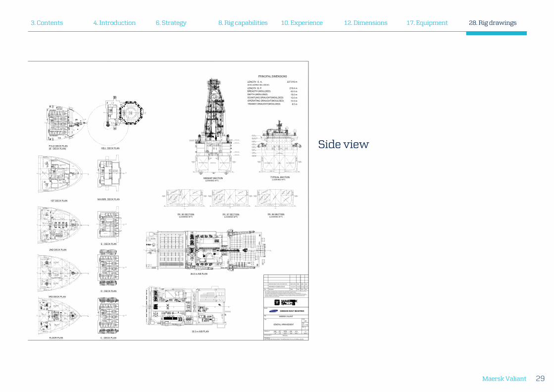
PRINCIPAL DIMENSIONS
LENGTH O. A. 227.819 m(EXCLUDING HELI.DECK)
LENGTH B. P. 219.4 mBREADTH (MOULDED) 42.0 mDEPTH (MOULDED) 19.0 mSCANTLING DRAUGHT(MOULDED) 13.0 mOPERATING DRAUGHT(MOULDED) 12.0 mTRANSIT DRAUGHT(MOULDED) 8.5 m
0 10 20 30 40 50 60 65 70 75 80 85 90 95 100 105 110 120 130 140 150B.L.
160B.L.
UP
UP
UPDN
106 110 120 130 140 150
С.L.
160
С.L.
106 110 120 130 140 150
С.L.
160
С.L.
SP
AR
E P
AR
TS
PA
CE
DRY BULK T.(C)
D.O TANK
AIRSUPPLY
UP
UP
UP
DN
DN
DN
DN
L.O. DRAINT. (S)
UPUP
UPD
N
UP
DN
DN H IP I
H I
LIFTINGHATCH
DN
UP
EX
H. D
UC
TFO
R LA
UN
DR
Y
DN
DN
A.P.T. (P)
DN
HATCH
DN
DRAINHOLDING
UP
DN
DN UP
LIFTINGSPACE
SU
PP
OR
T FOR
PR
OV
ISIO
NC
RA
NE
EX
H. V
EN
T FOR
AIR
CO
ND
. RO
OM
C.L.
OPEN
DN
DN
UP
DN
NO.1 HOLDB.T. (S)
F.P.
EXH. FORAIR COND.
DV.L.
STE
P
STABILIZER(TELESCOPIC)
AIR DRAUGHT : 111.318 m A/B
1
1
Drawing no.:
Title:
Sheet of
Rev. no.
Size:
Scale:
Rev. Description
Rig:
THIS CAD DRAWING IS CONVERTED FROM A PDF DOCUMENT WHICH IS THE PROPERTY OF SAMSUNG HEAVY IND. CO. LTD. AND MUST IN NO CASEWHOLLY OR PARTIALLY BE COPIED, SHOWN OR GIVEN TO ANY THIRD PARTY WITHOUT SAMSUNG'S CONSENT.THIS DOCUMENT CONTAINS PROPRIETARY AND CONFIDENTIAL INFORMATION WHICH BELONGS TO A.P. MOLLER - MAERSK A/S.IT IS LOANED FOR LIMITED PURPOSES ONLY AND REMAINS THE PROPERTY OF A.P. MOLLER - MAERSK A/S. REPRODUCTION, WHOLE OR IN PART,OR USE OF THIS DESIGN OR DISTRIBUTION OF THIS INFORMATION TO OTHERS IS NOT PERMITTED WITHOUT THE EXPRESS WRITTEN PERMISSION OFA.P. MOLLER - MAERSK A/S. THIS DOCUMENT IS TO BE RETURNED TO A.P. MOLLER - MAERSK A/S UPON REQUEST AND IN ANY EVENT UPONCOMPLETION OF USE FOR WHICH IT WAS LOANED.
DrawDate App.Chkd.
Rig SFI No.NumberCode Sheet- - - -
841 x 1700
CONFIDENTIALUNAUTHORIZED USE OR DISCLOSURE OF THIS MATERIAL RESULTS IN CIVIL OR CRIMINAL LIABILITIES.
Builder:
SAMSUNG HEAVY INDUSTRIES
SHI Drawing no.:
MAERSK VALIANT
GENERAL ARRANGEMENT
VAL 02 1030 001 101
1:400
1
1/1
PF10110
- PREPARED BY GENERAL DESIGN 13.02.2014 W.S.Kim K.B.Chung Y.H.Kim
1 UPDATED DUE TO VAL-2014-300714-01 28-07-2015 PKH DAM JAH
Rig drawings
Top view
4. Introduction3. Contents 6. Strategy 12. Dimensions8. Rig capabilities 10. Experience 17. Equipment 28. Rig drawings
Maersk Valiant 29
Side view
MOONPOOL
BALLASTPUMP ROOM
DRAI
N HO
LDIN
G T
.(P&S
)
CENT
. STE
RN T
HRUS
TER
ROO
M
ENGINE ROOM(C,P&S)
VOID(C)
NO.2 HOLD
B.T
.(P&S
)
BASE OIL T.(P)
CABLE TRUNK(P&S)
FWD. AUX. MACH. R
M(C)
NO.1 F.W
.T.(P&S)
CEN
TER
BO
W T
HR
UST
ER R
M
ACCOMMODATION SPACE
SWBD ROOM(C,P&S)
ENGINE WORKSHOP
ELEC. WORKSHOP
& STORE
NO.1 FWD D/B W.B.T.(C)
E.C.R(C)
PORT & STBDSTERNTHRUSTER RM
SECONDARY ESC WAY (P&S)
NO.6 W.B.T. (P&S)
ROPE
STORE(P)
PURIFIERROOM(P&S)
NO.2 HOLD
B.T.
(C)
PORT
& ST
BD B
OW T
HRUSTER
RM
3RD DECK (10.500m A/B)
2ND DECK (14.580m A/B)
NO.4 W.B.T.(P&S)
NO.5 HOLD B.T.(P&S)
H.P
.R. C
OM
P'T
(P&S
)
H.P
.R. C
OM
P'T
(P&S
)
NO.3. W.B.T.(P
&S)
NO.3. HOLD B.T(P&S)
NO.2. W.B.T.(P&S)
NO.4. HOLD B.T.(P
&S)
BOSUNSTORE C.L.
NO.2 F.W
.T.(S)
A.P.T
.(P&S)
DRILLING W.T.(P
&S)
VOID
B.W.EXH.AIRSPACE
VOID
VOID
AIR COND. UNIT ROOM(C)
STAIRWAY
S/C(P
&S)
NO.1
HO
LD B
.T.(C
)
NO.1 AFT W.B.T. (P&S)
NO.1 HOLD B.T.(S)
NO. 3,4
RESERVE
PIT.T.(S)
DRY BULK T.(C)
NO.1 BRIN
E
T.(P)
WASTE
MUD T.(S)
NO. 1.2
RESERVE
PIT.T.(S)
AGITATOR
SPACE(S)
NO.1 HOLD B.T.(P)
NO.2,3 B
RINE
T.(P)14.500 m A/B
8.100 m A/B7.300 m A/B
12.900 m A/B
NO.1
D.O
.STO
R. T
.(P&S
)
NO.5 W.B.T.(P
&S)
NO
.2 D
.O.S
TOR
. T.(P
&S)
D.O
. SER
V. T
.(P&S
)
C/D
SEP.BILGEOIL T. PURIFIER SLUDGE
T.(P&S)BILGEHOLD. T.
S/C(P&S)
B/W
L.O.S
TOR.T.
L.O.SETT.T.
EM'C
Y EXIT(P&S)
11.600m A/B
NO.6 RESERVE
PIT. T.(P
)
NO.2 F.W.T.(P)
TRANS-FORMERSPACE
12.900m A/B
VOID
D.O. OVERFLOW
DRAIN T.(P&S)
SECONDARY ESC. WAY FWD (P&S)
C/DC/D
C/D
C/D
UP
EXH.VENT
BURNER BOOMPEDESTAL
OXY.RM
ACERM
PAINTSTORE
WATER MIST& INERGENROOM
HYD. POWERPACK ROOM
INCIN. RM
FRESH AIRINTAKE TRUNKVENT FOR AIRCOND.
LIFTINGSPACE
MESS ROOM
C.G.L.
0 10 20 30 40 50 60 65 70 75 80 85 90 95 100 105 110 120 130 140 150С.L.
160
UP
UP UP
C.G.L
CREW(2P)
AIRRETURN
CREW(2P) CREW(2P) CREW(2P) CREW(2P)CREW(2P)
CREW(2P)
CREW(2P)
CREW(2P)
CREW(2P)
CREW(2P)
CREW(2P)CREW(2P)
CREW(2P)CREW(2P)
CREW(2P) CREW(2P)
CREW(2P) CREW(2P)
CREW(2P) CREW(2P) CREW(2P)
CREW(2P)
CREW(2P)CREW(2P)CREW(2P)CREW(2P)CREW(2P)CREW(2P)
EL.TRUNK
EL.TRUNK
PIPESPACE
AIRRETURN
UP
DN
DN UP
LIFT
UP
DN
AU
X.M
AC
H.
RM
.HA
TCH
PIPESPACE
AIRRETURNUP
DN
CREW(2P) CREW(2P) CREW(2P) CREW(2P) CREW(2P)CREW(2P)
CREW(2P)
CREW(2P)
CREW(2P)
CREW(2P)
CREW(2P)CREW(2P)
CREW(2P)
CREW(2P) CREW(2P) CREW(2P)
CREW(2P)CREW(2P)CREW(2P)
CREW(2P) CREW(2P) CREW(2P)
CREW(2P)
CREW(2P)CREW(2P)CREW(2P)CREW(2P)CREW(2P)CREW(2P)
DN UP
LIFT
EL.TRUNK
EL.TRUNK
AIRRETURN
LINEN LOCKER
LINEN LOCKER
UP
DN
NAVIGATIONINSTRUMENT
ROOM
DP BACK-UPROOM
COMMON OFFICE
CONFERENCE ROOM-1
CABELTRUNK
CREW(2P) CREW(2P) CREW(1P)CREW(1P)
CREW(1P)
CREW(1P)
CREW(1P)
CREW(1P)
CREW(1P)
CREW(1P)
CREW(1P)
CREW(1P)
DOCUMENT ROOM
CONFERENCE ROOM-2
CONFERENCE ROOM-3
CGL
UP
DN
UP
DN
EL.TRUNK
EL.TRUNK
LOBBY
DN UP
PIPESPACE
AIRRETURN
LIFT
LOC
KE
R
LOC
KE
R
AIRSUPPLY
OFFICERSCHANGING
ROOM
OIM OFFICE
BA
RG
E E
NG
./A
SS
. BA
RG
EE
NG
.OFFIC
E
MAINTENANCE/
ASS. MAIN ENG. OFFICE
SE
N. TO
OL P
US
HE
R/
TOO
L PU
SH
ER
OFFIC
E
MAERSKOFFICE
CLIENTOFFICE
OPEN OFFICE
WHEELHOUSE(INCL. CHART &RADIO SPACE)
CLIENTOFFICE
PIPE & EL.TRUNK
EL.TRUNK
DN UP
DN
UP
DN
UP
AIRSUPPLY
AIR
RE
TUR
N
PRINTERROOM
LIFT
AU
X.M
AC
H.
RM
.HA
TCH
DN
DN
DN
UP
VENT.(SUP)
VENT.
VOID
AHU ROOM
AHU ROOM
LANDINGSPACE
GENERALSTORE
VOID
LIFTINGSPACE
FRESH AIRINTAKE VENT
NO.1HOLD B. TK (C)
AUX.MACH.RM. EXH.VENT
DOME
C.F.W.EXP.TK
LIFTINGSPACE
ELECTRICSPACE
NO
.2 THR
US
TER
RO
OM
SECONDARYESCAPE WAY(P)
AHU ROOM
DN
VENT
SECONDARYESCAPE WAY(S)
VOID
NO
.1 THR
US
TER
RO
OM
NO
.3 THR
US
TER
RO
OM
RETURNTRUNK
UPDN
UP
UP DN
UP
UP
UP
SUPPLYTRUNK
UP
DN
VENT
UP
DNDN
VENT
CREW(2P) CREW(2P) CREW(2P) CREW(2P) CREW(2P)CREW(2P)
CREW(2P)
CREW(2P)CREW(2P) CREW(2P)
CREW(2P)CREW(2P)CREW(2P)
CREW(2P) CREW(2P)
CREW(2P)CREW(2P)
CREW(2P) CREW(2P)
CREW(2P)
CREW(2P)
CREW(2P)
CREW(2P)
CREW(2P)CREW(2P)CREW(2P)CREW(2P)CREW(2P)CREW(2P)
AU
X.M
AC
H.
RM
.HA
TCH
EL.TRUNK
EL.TRUNK
LINEN LOCKER
PIPESPACE
AIRRETURN
DN UP
LIFT
C.G.L
C.G.LAIR
RETURN
DN
UP
DN
UP
DN
DN
OPENING FOR FRESHAIR INTAKE OF EM'CY
GEN. ROOM
SE
CO
ND
AR
YE
SC
. WA
Y
SE
CO
ND
AR
YE
SC
. WA
Y
NO.1 AFT W.B.T.(S) NO.1 AFT W.B.T.(P)
AGITATOR SPACE(S)
BASE OIL T.(P)
NO.1 HOLD B.T.(S) NO.1 HOLD B.T.(P)
NO.4 RESERVE
PIT T.(S)
NO.3 RESERVE
PIT T.(S)
DRY BU
LK T
.(C)
DR
AIN
HO
LDIN
GT.
(S)
SE
CO
ND
AR
YE
SC
. WA
Y
SE
CO
ND
AR
YE
SC
. WA
Y
NO.1 AFT W.B.T.(S) NO.1 AFT W.B.T.(P)
AGITATOR SPACE(S)
BASE OIL T.(P)
NO.1 HOLD B.T.(S) NO.1 HOLD B.T.(P)
NO.2 RESERVE
PIT T.(S)
NO.1 RESERVE
PIT T.(S)
DRY BU
LK T
.(C) S
EC
ON
DA
RY
ES
C. W
AY
SE
CO
ND
AR
YE
SC
. WA
Y
NO.1 AFT W.B.T.(S) NO.1 AFT W.B.T.(P)
AGITATOR SPACE(S)
NO.3 BRIN
E
T.(P)
NO.1 HOLD B.T.(S) NO.1 HOLD B.T.(P)
NO.5 RESERVE
PIT T.(S)
WASTE M
UD T.(S)
DRY BU
LK T
.(C)
NO.2 BRIN
E
T.(P)
VOID
GAME ROOM
CHANGING ROOM(MAN) VOID
NO
.1 THR
USTER
RO
OMLAUNDRY
PRAYERROOM
IRONINGROOM
LEAVELOCKER LINEN LOCKER
CHANGING ROOM(WOMEN)
UP
UPDN
GYMNASIUM
VOID
NO
.3 THR
US
TER
RO
OM
NO
.2 THR
US
TER
RO
OM
TELE.BO
OTH
W.C
EL.TRUNK
EL.TRUNK
LOCKER
NO.1HOLD B.T. (C)
SECONDARYESCAPE WAY(P)
SECONDARYESCAPE WAY(S)
FWD.AUX.MACH.RM.EXH.VENT
CLEAN COVERALLSTORE
PIPESPACE
AIRRETURN
VENT.(EXH.)
VENT.(SUP.)
VENT.(SUP.)
UPDN
UP
UPDN
C.G.L.
AIRSUPPLY
VENT
VENT
LIFTINGSPACE
UP DN
VENT.
VENT.(EXH.)
LIFT
DN
UP
LIFTINGSPACE
LIFTINGSPACE
UP
UP
EX
H. FO
RA
IR C
ON
D.
DN TO AHUROOM
LIFTINGSPACE
DRILLING W.T. (P)
AUX.MACHINERYROOM
DN
DN
DN
UP
UP
UP
3022C.L.
UP
UP
UP
UP
UP
UP
UP
UP
VENT
VENT
VENT
VENT
VENT
VENT
DN
DN
DN
DN
DN
DN
DN
DN
DN
C.L.3022
C.L.C.L.3022
C.L.C.L.
3022C.L.C.L.
3022C.L.C.L.
STR.1 PLAN STR.2 PLAN FUNNEL TOP PLAN
"B" DECK PLAN "C" DECK PLAN
NO.1HOLD B. T.(C)
NO.1AFT W.B.T. (P)
DRILLING W.T. (P)
VOID
DRILLING W.T. (S)
NO.1AFT W.B.T. (S)
NO.1F.W. T. (P)FWD. AUX
MACHINERYROOM
LIFTINGSPACE
VOID
NO.1F.W. T. (S)
VOID
VOID
DN
UP
UP
UP
UP
DNUP
UP
UP
UPUP
UP
DN
DN
DRILLING W.T. (S)
VOID
VOID
VOID
VOID
NO.1F.W.T. (P)
NO.1F.W.T. (S)
NO.1HOLD B.T. (C)
PORT BOWTHRUSTERROOM
STBD BOWTHRUSTERROOM
DN UP
DN
UP
NO.1AFT W.B.T. (P)
NO.1AFT W.B.T. (S)
UP
UP
DN
UPDN
UPDN
UP
PORTENG. RM
NO.2 M.D.O.STOR. T. (P)
M.D.O.SERV.T. (P)
BALLASTPUMP ROOM
NO.2 M.D.O.STOR. T. (S)
M.D.O.SERV.T. (S)
STBDENG. RM
CENT.ENG. RM
NO.6W.B. T. (P)
NO.6W.B. T. (S)
A.P. TK (S)
A.P. T. (P)
LANDINGAREA
LANDINGAREA
LANDINGAREA
NO.5 W.B. T. (S)
UP
UP
DN
DN
THRUSTER
THRUSTER
THRUSTER
DN
DN
UP
UP
UP
UP
NO.6 W.B. T. (P)
NO.2 M.D.O.STOR. TK (P)
BALLASTPUMP ROOM
NO.2 M.D.O.STOR. TK (S)
NO.6 W.B. T. (S)
VENT
CENT ENGINE RM
PORT ENGINE RM
STBD ENGINE RM
LIFTINGHATCH
PORT TRANS-FORMER SPACE
ELEC.WORKSHOP& STORE
ENG.WORKSHOP
CENT TRANS-FORMER SPACE
STBD STERNTHRUSTER RM
VENT
VENT
A.P. T. (S)
A.P. T. (P)
VENT
EM'CYEXIT
L.O. DRAINT. (P)
NO.2 F.W. T. (S) ENG. STORE
STBD TRANS-FORMER SPACE
VENT
EM'CYEXIT
EM'CYEXIT
VENT
L.O.DAILYT.
UPDN
UP
UP
UP
UP
UP
UP
DN
LIFTINGHATCH
UP
DN
UPD
N
NO.4 HOLD. B.TK.(S) NO.4 HOLD. B. TK.(P)
NO. 1 THRUSTER ROOM
EXH. TRUNKFOR LAUNDRY
DUCTTRUNK
DUCTTRUNK
ACCESS TRUNK FORNO. 1 THRUSTER ROOM
ACCESS TRUNKFOR BOSUN STROKE
SE
CO
ND
AR
YE
SC
. WA
Y
SE
CO
ND
AR
YE
SC
. WA
Y
W.B.T. (S) W.B.T. (P)
NO.5 HOLD B.T.(S) NO.5 HOLD B.T.(P)VOID(C)MOON POOL
W.B.T. (S) W.B.T. (P)
SE
CO
ND
AR
YE
SC
. WA
Y
SE
CO
ND
AR
YE
SC
. WA
Y
H.P.R.COMP.
H.P.R.COMP.
H.P.R.COMP.
H.P.R.COMP.
DRAINHOLDINGT.
CENT. STERNTHRUSTERROOM
EM'CY EXIT
EM'CY EXIT
EM'CY EXIT
STBD. STERNTHRUSTER RM
PORT STERNTHRUSTERROOM
ENGINE ROOM (P)
ENGINE ROOM (C)
ENGINE ROOM (S)
NO.6 W.B.T.(S
)
NO.6 W.B.T.(P
)NO.5 HOLD B.T.(P)
NO.5
W.B
.T.(P
)
NO.1 D
.O. S
TOR. T
.(P)
S/C
S/C
A.P.T.(S)
A.P.T.(P)
BILG
E H
OLD
. T.
PURIFIERROOM (S)
PURIFIERROOM (P)
PURIFIERSLUDGE T.(S)
PURIFIERSLUDGE T.(P)
SEP. BILGE
OIL.T.(C)
D.O
. SE
RV
.T(S
)D
.O. S
ER
V.T
(P)
BALLASTPUMP ROOM
DRAIN HOLDING
.T.(S)
DRAIN HOLDING
.T.(P)
NO.5
W.B
.T.(S
)
NO.1 D
.O. S
TOR. T
.(S)
NO.2
D.O
.ST
OR.
T.(S
)
NO
.2 D
.O.
STO
R. T
.(P)
MOONPOOL
VOID
NO.3 W.B. T
.(P)
NO.5 HOLD B.T.(S)
NO.4 W.B. T
.(S)
NO.4 W.B. T
.(P)
VOID(C)
NO.4 HOLD B.T.(P)
NO.3 HOLD B.T.(P)
NO.3 HOLD B.T.(S)
NO.4 HOLD B.T.(S)
NO.3 W. B.T.(S)
DRY BULK T.(C)
BASE OIL T.(P)NO.2 W.B. T.(P
)
NO.2 HOLD
B.T.(P
)
NO.2 HOLD B.T.(C)
NO.2 HOLD
B.T.(S
)NO.2 W. B
.T.(S)
NO.1 HOLD
B.T
.(C)
NO.1 AFT W.B.T.(P
)
NO.1 HOLD B.T.(P)
VOID
VOID
NO.1BRINET.(P)
NO.3BRINET.(P)
NO.2BRINET.(P)
NO.1RESERVEPIT T.(S)
NO.2RESERVEPIT T.(S)
NO.4RESERVEPIT T.(S)
NO.3RESERVEPIT T.(S)
WASTEMUD T.(S)
NO.1 AFT W.B.T.(S
)
PORTBOW THRUSTERROOM
STB'DBOW THRUSTERROOM
DRILLING W.T.(S)
DRILLING W.T.(P)VOID
VOID
BILG
EHO
LD T
.
FWD. AUX. M
ACH. RM.
NO.1 FW
DD/B
W.B
..T.(C
)
ECHO SOUNDEM LOGTRANSDUCER NO.1
F.W.T.(S
)
NO.1
F.W.T.(P
)
VOID
CENTERBOWTHRUSTERROOM
NO.5RESERVEPIT T.(S) NO.1 HOLD
B.T. (S)
0 10 20 30 40 50 60 65 70 75 80 85 90 95 100 105 110 120 130 140 150С.L.
160
B/W
B/W
B/W
NO.2
F.W.T.(S)
ROPE
STORE(P)
B/W
B/W
B/W
B/W
B/W
B/W S/C
S/C
NO.6RESERVEPIT T.(S)
S/CB/W
S/C
S/C
S/C
NO.2F.W.T.(P)
D.O.OVERFLOW/DRAIN T.(S)
D.O.OVERFLOW/DRAIN T.(P)
O/D
C/D
C/D
C/D
F'CLE DECK PLAN(B - DECK PLAN) HELI. DECK PLAN
NAV/BRI. DECK PLAN1ST DECK PLAN
2ND DECK PLAN
E - DECK PLAN
D - DECK PLAN
3RD DECK PLAN
FLOOR PLAN C - DECK PLAN
FR. 95 SECTION(LOOKING AFT)
FR. 97 SECTION(LOOKING AFT)
FR. 99 SECTION(LOOKING AFT)
MIDSHIP SECTION(LOOKING AFT)
TYPICAL SECTION(LOOKING AFT)
NO.5 W.B.T. (S)
NO.5 W.B.T. (P)
NO.1 M.D.O. STOR. TK (P)
NO.1 M.D.O. STOR. TK (S)
DRAIN HOLDING T.(P)
DRAIN HOLDING T.(S)
VOID(C)
NO.5 HOLDB.T. (S)
NO.5 HOLDB.T. (P)
NO.1 M.D.O. STOR. T. (P)
DRAIN HOLDING T.(P)
DRAIN HOLDING T.(S)
NO.1 M.D.O. STOR. T. (S)
VOID(C)
NO.5 W.B.T. (P)
NO.5HOLDB.T. (P)
NO.5HOLDB.T. (S)
NO.4W.B.T.(P)
NO.4W.B.T.(S)
3RD DECK PLAN
FLOOR PLAN
2ND DECK PLAN
TANK TOP PLAN
UPPER DECK PLAN
VOID (C)
DNUPEM'CY
EXIT (S)
DN
DN
UP
UPEM'CYEXIT (P)
EM'CYEXIT (C)
DN
UP
UP DN
VENT
VENT
DN
UP
DN
SECONDARY ESCAPE WAY (P)
SECONDARY ESCAPE WAY (S)
A.P. T. (S)
A.P. TK (P)
NO.2 F.W. T. (P)
NO.2 F.W. T. (S)L.O. SETT. T. (S) L.O. STOR. T. (S)
VENT AREA
PORT ENGINE RM
CENT ENGINE RM
STBD ENGINE RM
L.O. SETT. T. (P) L.O. STOR. T. (P)
STBD ENG. RM.NO.1 M/G/ENGINE
STBD ENG. RM.NO.2 M/G/ENGINE
ENGINECONTROLROOMLI
FTIN
GSP
ACE
HATC
H
CENT MSBD RM
BALLASTPUMPROOM
PORT MSBD RM
STBD MSBD RM
NO.2 M.D.O.STOR. TK (S)
NO.2 M.D.O.STOR. T. (P) NO.1 M.D.O. STOR. T. (P)
DRAIN HOLDING T. (P)
DRAIN HOLDING T. (S)
NO.1 M.D.O. STOR. T. (S) NO.5 HOLDB. T. (S)
NO.5 HOLDB. T. (P)
CENT STERNTHRUSTER RM
STBD STERNTHRUSTER RM
ROPE STORE
LIFTINGSPACE
LIFTINGSPACE
E/R
CR
AN
E
E/R
CR
AN
E
E/R
CR
AN
E
DN
DN DN
UP
UP
DN
DN
UP
DN
DN
UP
DNDN
LOBBY
DNDN
UP
DN
UPUP
UP
PORT STERNTHRUSTER RM
UPUP
DN DN
DN
DN
UP
UP UP
UPUP
36.0 m A/B PLAN
NO.5 HOLD B.T.(P)
NO.5 HOLD B.T.(S)
VOID
NO.3 HOLD B.T.(P)
NO.4 HOLD B.T.(S)
NO.2 HOLD B.T.(P)
NO.3 HOLD B.T.(S)NO.2 HOLD B.T.(S)
BASE OIL T. (P)NO.4 HOLD B.T.(P)
NO.2
HO
LD B
.T.(C
)
DRAIN HOLDING
T (S)
DRAIN HOLDING
T (P)
NO.1 D.O
. STO
R. T.(P
)
NO.1 D.O
. STO
R. T.(S
)
SWBDROOM(S)
SWBDROOM(P)
SWBDROOM(C)
BALLASTPUMP ROOM
NO
.2 D
.O.
STO
R. T
.(P)
NO
.2 D
.O.
STO
R. T
.(S)
NO.1HOLD B.T.(P)
NO.1BRINET.(P)
NO.3BRINET.(P)
NO.2BRINET.(P)
PORT BOWTHRUSTER RM.
CABLE TRUNK(P)
CABLE TRUNK(S)STBD BOWTHRUSTER RM.
AGITATOR SPACE(S)
A.P.T. (S)
SECONDARY ESC. WAY FWD (S)
SECONDARY ESC. WAY FWD (P)SECONDARY ESCAPE WAY (P)
SECONDARY ESCAPE WAY (S)
DN
DN
DN
DN
DN
UP
DN
DN
UP
NO.1 H
OLD B
.T.(C
)
UP
DN
DN
DN
UP
DN
ACC. LADDER
ACC. LADDER
UP
MOON POOL
EM'CY GENERATORROOM
PIPESPACE
GALLEY
MEAT ROOM VEGETABLE ROOM
DAIRY
LOBBY
FISHROOM
SLOPCHEST
EL. TRUNK
DRY PROVISIONSTORE
AUX. MACH.EXH. VENT
FIRE CONTROLSTATION
LIFT &STAIRWAY
DNUP
EL. TRUNK
SC
ULL
ER
YAIR
INTA
KE
TRU
NK
FO
RM
AC
H. R
OO
M
AIRRETURN
CA
MP
BO
SS
OFF
ICE
CATERINGMESS ROOM
GARBAGESTORE
LIFT LOBBY
NO
.1 T
HR
US
TER
RO
OM
UP
DN
UP
NO
.1 T
HR
US
TER
RO
OM
PIPESPACE
EL. TRUNK
AUX. MACH.EXH. VENT
BOSUN STORE
UP DN
UP
DN
UP
DN
AIR
INTA
KE
TRU
NK
FOR
MA
CH
. RO
OM
FRE
SH
AIR
INTA
KE
FOR
GA
LLEY
LIBRARY
OPENINGFOR FRESH AIR
INTAKE OF EM'GYGEN. ROOM
RECREATION ROOM(SMOKER)
RECREATION ROOM(NON SMOKER)
IT CAFE
AIRRETURN
TREATMENTROOM
HOSPITAL LINERLOCKER
GENERAL ELECTRICROOM
FRE
SH
AIR
TRU
NK
FOR
GA
LLEY
CREW(2P) CREW(2P)
CREW(2P) CREW(2P)
CREW(2P) CREW(2P)
CREW(2P) CREW(2P)
CREW(2P) CREW(2P)
CREW(2P) CREW(2P)
CREW(2P) CREW(2P)
CREW(2P)
CREW(2P)
CREW(2P)
CREW(2P)
CREW(2P)
CREW(2P)
CREW(2P)
EL. TRUNK
AIRRETURN
C.G.L
LOBBY
LIFT
UP UP
23.0 m A/B PLAN(A - DECK PLAN)
PROFILE
B.O.P.AREA
30.0 m A/B PLAN
UP
UP
UPDN
VENT UP
UP
DN
DN
UP
DN
UP
DN
UP
UP
UP
UP
UP
UP
UP
UP
UP
UP
DN
UP
A.P. 6 10 16 20 24 31 34 41 45 49 55 61 64 65 66 6713 27 37 52 582
A.P. 6 10 16 20 24 31 34 41 45 49 55 61 64 65 66 6713 27 37 52 582
A.P. 6 10 16 20 24 31 34 41 45 49 55 61 64 65 66 6713 27 37 52 582 0 10 20 30 40 50 60 65 70 75 80 85 90 95 100 105 110 120 130 140 150С.L.
160
106 110 120 130 140С.L. С.L.
106 110 120 130 140С.L. С.L.
106 110 120 130 140С.L. С.L.
106 110 120 130 140С.L. С.L.
106 110 120 130 140 150
С.L.
160102
106 110 120 130 140 150
С.L.
160102
106 110 120 130 140 150
С.L.
160102
106 110 120 130 140 150
С.L.
160102
55 60 64 65 70 75 80 85 90 95 100 105 110С.L.
75 80 85 90 95 100 105С.L.
S.L.W.L. S.L.W.L.S.L.W.L. S.L.W.L. S.L.W.L. S.L.W.L.
S.L.W.L. S.L.W.L.S.L.W.L. S.L.W.L.
S.L.W.L. S.L.W.L.
8.8 m 8.8 m 27.2 m 4.8 m 9.6 m 28.8 m 22.4 m 35.2 m 25.6 m 12.8 m 21.6 m 12.2m 8.370m
(147.2 m)(112.0 m)(89.6 m)(60.8 m)(51.2 m)(46.4 m)(19.2 m)(10.4 m) (172.8 m) (185.6 m) (207.2 m) (219.4 m) (227.770)
F.S: 800 W.S: 3,200 W.S: 3,200 F.S: 800FR.82+0.9M
(DISTANCE FROM A.P.)
A.P.
B.L. B.L. B.L. B.L.
B.L. B.L.B.L. B.L.B.L. B.L.
C.L.C.L. C.L.
PRINCIPAL DIMENSIONS
LENGTH O. A. 227.819 m(EXCLUDING HELI.DECK)
LENGTH B. P. 219.4 mBREADTH (MOULDED) 42.0 mDEPTH (MOULDED) 19.0 mSCANTLING DRAUGHT(MOULDED) 13.0 mOPERATING DRAUGHT(MOULDED) 12.0 mTRANSIT DRAUGHT(MOULDED) 8.5 m
0 10 20 30 40 50 60 65 70 75 80 85 90 95 100 105 110 120 130 140 150B.L.
160B.L.
UP
UP
UPDN
106 110 120 130 140 150
С.L.
160
С.L.
106 110 120 130 140 150
С.L.
160
С.L.
SP
AR
E P
AR
TS
PA
CE
DRY BULK T.(C)
D.O TANK
AIRSUPPLY
UP
UP
UP
DN
DN
DN
DN
L.O. DRAINT. (S)
UPUP
UPD
N
UP
DN
DN H IP I
H I
LIFTINGHATCH
DN
UP
EX
H. D
UC
TFO
R LA
UN
DR
Y
DN
DN
A.P.T. (P)
DN
HATCH
DN
DRAINHOLDING
UP
DN
DN UP
LIFTINGSPACE
SU
PP
OR
T FOR
PR
OV
ISIO
NC
RA
NE
EX
H. V
EN
T FOR
AIR
CO
ND
. RO
OM
C.L.
OPEN
DN
DN
UP
DN
NO.1 HOLDB.T. (S)
F.P.
EXH. FORAIR COND.
DV.L.
STE
P
STABILIZER(TELESCOPIC)
AIR DRAUGHT : 111.318 m A/B
1
1
Drawing no.:
Title:
Sheet of
Rev. no.
Size:
Scale:
Rev. Description
Rig:
THIS CAD DRAWING IS CONVERTED FROM A PDF DOCUMENT WHICH IS THE PROPERTY OF SAMSUNG HEAVY IND. CO. LTD. AND MUST IN NO CASEWHOLLY OR PARTIALLY BE COPIED, SHOWN OR GIVEN TO ANY THIRD PARTY WITHOUT SAMSUNG'S CONSENT.THIS DOCUMENT CONTAINS PROPRIETARY AND CONFIDENTIAL INFORMATION WHICH BELONGS TO A.P. MOLLER - MAERSK A/S.IT IS LOANED FOR LIMITED PURPOSES ONLY AND REMAINS THE PROPERTY OF A.P. MOLLER - MAERSK A/S. REPRODUCTION, WHOLE OR IN PART,OR USE OF THIS DESIGN OR DISTRIBUTION OF THIS INFORMATION TO OTHERS IS NOT PERMITTED WITHOUT THE EXPRESS WRITTEN PERMISSION OFA.P. MOLLER - MAERSK A/S. THIS DOCUMENT IS TO BE RETURNED TO A.P. MOLLER - MAERSK A/S UPON REQUEST AND IN ANY EVENT UPONCOMPLETION OF USE FOR WHICH IT WAS LOANED.
DrawDate App.Chkd.
Rig SFI No.NumberCode Sheet- - - -
841 x 1700
CONFIDENTIALUNAUTHORIZED USE OR DISCLOSURE OF THIS MATERIAL RESULTS IN CIVIL OR CRIMINAL LIABILITIES.
Builder:
SAMSUNG HEAVY INDUSTRIES
SHI Drawing no.:
MAERSK VALIANT
GENERAL ARRANGEMENT
VAL 02 1030 001 101
1:400
1
1/1
PF10110
- PREPARED BY GENERAL DESIGN 13.02.2014 W.S.Kim K.B.Chung Y.H.Kim
1 UPDATED DUE TO VAL-2014-300714-01 28-07-2015 PKH DAM JAH
4. Introduction3. Contents 6. Strategy 12. Dimensions8. Rig capabilities 10. Experience 17. Equipment 28. Rig drawings
DISCLAIMER: The content of this brochure is indicative only and does not constitute a legal specification of any kind.
Head office:Maersk DrillingLyngby Hovedgade 852800 Kgs. LyngbyDenmarkTelephone: +45 63 36 00 00www.maerskdrilling.com
Visiting offices:
DenmarkLyngby Hovedgade 852800 Kgs. LyngbyDenmark
NorwayMoseidveien 19P.O. Box 134 Forus4065 StavangerNorway
AberdeenCity WharfShiprowAberdeen AB11 5BY United Kingdom
Ghana2nd Floor, One Airport SquarePlot 21Airport CityAccraGhana
Singapore200 Cantonment Road#06-02 SouthpointSingapore 089763
USA2500 City West BoulevardSuite 1850HoustonTexas 77042USA
Follow us to learn more
www.linkedin.com/company/maerskdrilling
www.facebook.com/maerskdrilling
www.twitter.com/maerskdrilling
www.instagram.com/maerskdrilling