2.4. drilling techniques 2.4.1. drilling technique general...
TRANSCRIPT
The Study on Groundwater Resources Potential in Kabul Basin in Afghanistan
Sector 6-91
2.4. Drilling Techniques
2.4.1. Drilling Technique General (Introduction to Well Drilling)
a. WELL DRILLING MACHINE
(1) Rotary Drilling Machine
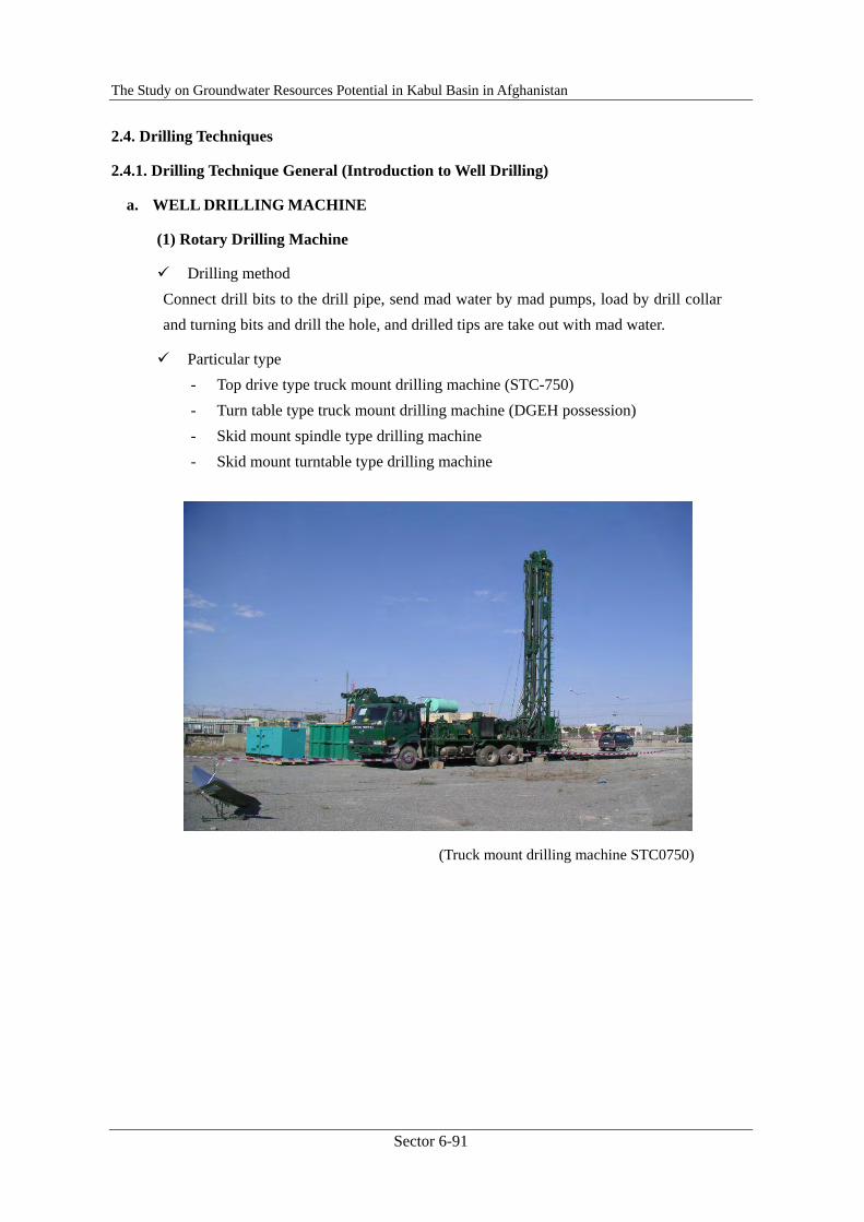
Drilling method Connect drill bits to the drill pipe, send mad water by mad pumps, load by drill collar and turning bits and drill the hole, and drilled tips are take out with mad water.
Particular type - Top drive type truck mount drilling machine (STC-750) - Turn table type truck mount drilling machine (DGEH possession) - Skid mount spindle type drilling machine - Skid mount turntable type drilling machine
(Truck mount drilling machine STC0750)
The Study on Groundwater Resources Potential in Kabul Basin in Afghanistan
Sector 6-92
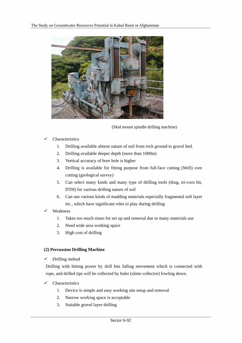
(Skid mount spindle drilling machine)
Characteristics 1. Drilling available almost nature of soil from rock ground to gravel bed. 2. Drilling available deeper depth (more than 1000m) 3. Vertical accuracy of bore hole is higher 4. Drilling is available for fitting purpose from full-face cutting (Well) core
cutting (geological survey) 5. Can select many kinds and many type of drilling tools (drug, tri-corn bit,
DTH) for various drilling nature of soil 6. Can use various kinds of madding materials especially fragmental soft layer
etc., which have significant roles to play during drilling Weakness
1. Takes too much times for set up and removal due to many materials use 2. Need wide area working space 3. High cost of drilling
(2) Percussion Drilling Machine
Drilling mehod Drilling with hitting power by drill bits falling movement which is connected with rope, and drilled tips will be collected by baler (slime collector) fowling down.
Characteristics 1. Device is simple and easy working site setup and removal 2. Narrow working space is acceptable 3. Suitable gravel layer drilling
The Study on Groundwater Resources Potential in Kabul Basin in Afghanistan
Sector 6-93
4. Cheap drilling cost Weakness
1. Drilling difficulty for hard rock layer 2. Drilling depth limit is around 200m depth 3. Poor support against collapse of borehole wale 4. Percussion drilling only and not available core drilling for geological survey 5. Drilling efficiency is lower and takes a lot of drilling time
b. Well materials
(1) Casing pipe
Casing pipes are made from steel, and following are classification of the pipes(Ref. Casing work)
Surface casing pipe Set for removal of surface soil collapse, and insert approx. 10m depth from GL.
Pump housing casing pipe Insert for installation of lifting pump, cementing outer case for prevent water flow in from shallow aquifer where high potential contaminated water holds.
Casing pipe Install area for non aquifer zone and prevent collapse of bore hole and shut down unnecessary ground water.
Screen pipe Install aquifer area and intake ground water, now use continuous-slot screen which is higher opening ratio, made by stainless steel. The others are slotted screen which is lower opening ration, and have demerit to enter sand from slit.
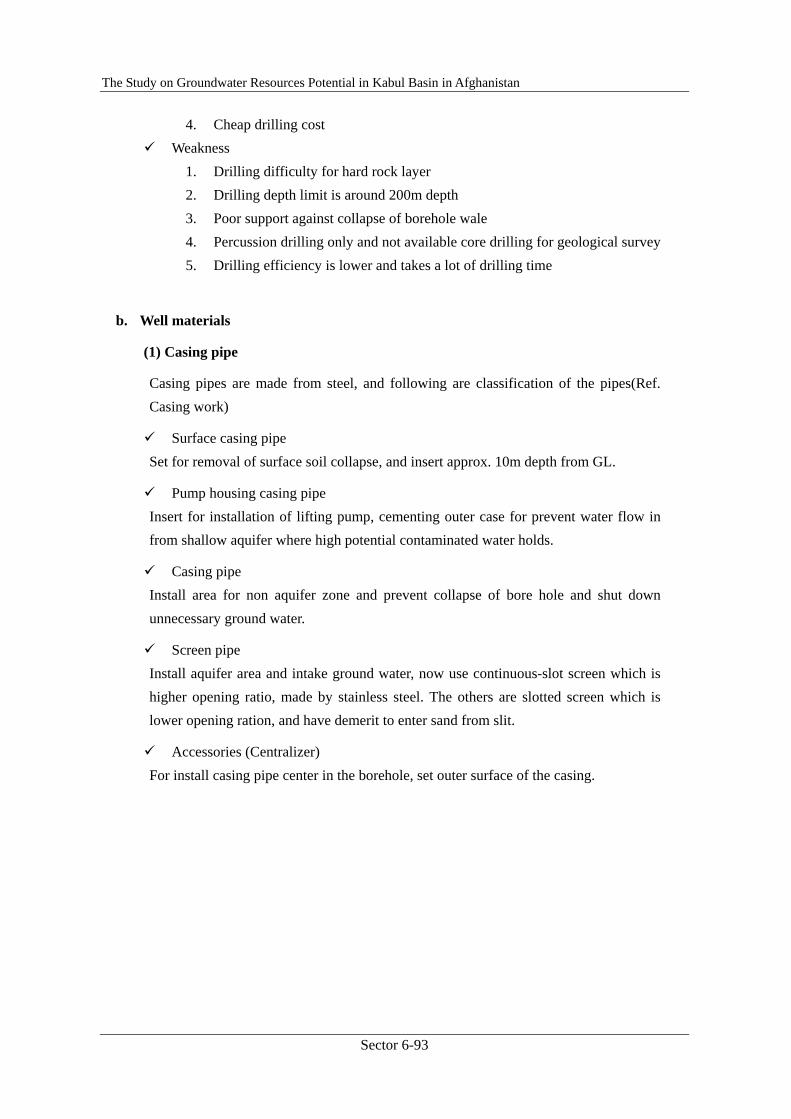
Accessories (Centralizer) For install casing pipe center in the borehole, set outer surface of the casing.
The Study on Groundwater Resources Potential in Kabul Basin in Afghanistan
Sector 6-94
(Centralizer)
(2) Sand filling
Fill sand outside of screen pipe around aquifer zone and take ground water, preventing collapse of aquifer layer.
Round shape sands from 3~9mm is preferable. Prepare volume of sand 20~30% of setting Screen Pipe volume, and fill sand a
certain volume by little and little for preventing clog outside screen.
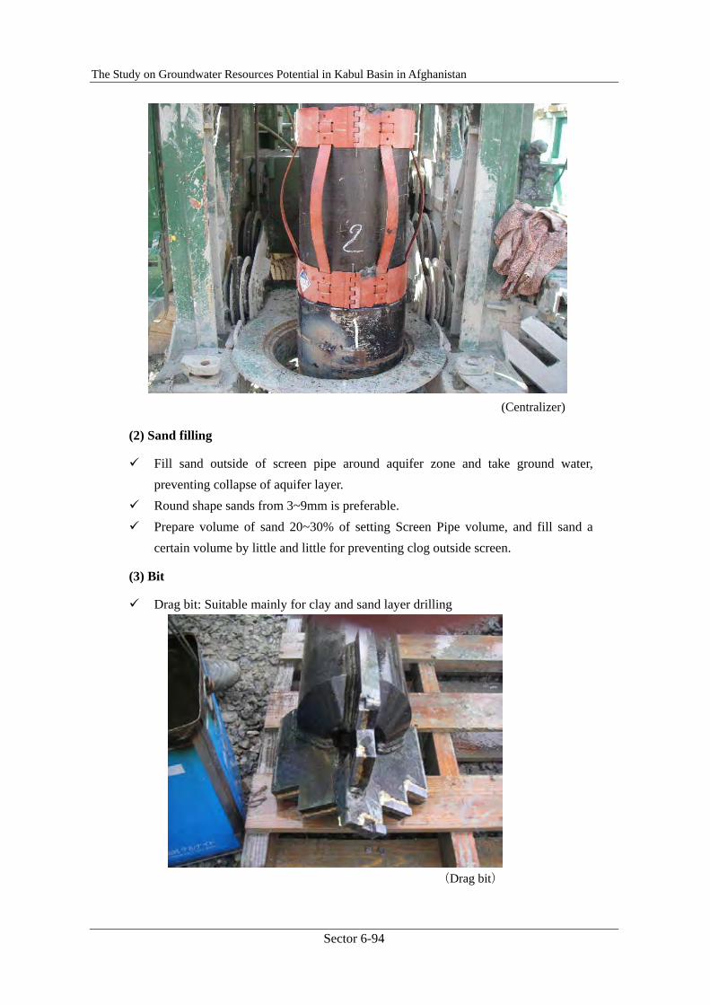
(3) Bit
Drag bit: Suitable mainly for clay and sand layer drilling
(Drag bit)
The Study on Groundwater Resources Potential in Kabul Basin in Afghanistan
Sector 6-95
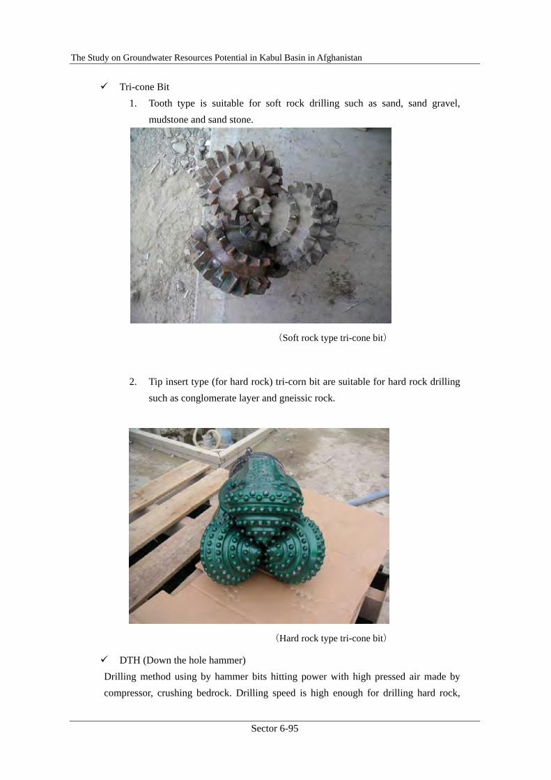
Tri-cone Bit 1. Tooth type is suitable for soft rock drilling such as sand, sand gravel,
mudstone and sand stone.
(Soft rock type tri-cone bit)
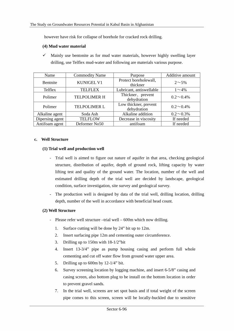
2. Tip insert type (for hard rock) tri-corn bit are suitable for hard rock drilling such as conglomerate layer and gneissic rock.
(Hard rock type tri-cone bit)
DTH (Down the hole hammer) Drilling method using by hammer bits hitting power with high pressed air made by compressor, crushing bedrock. Drilling speed is high enough for drilling hard rock,
The Study on Groundwater Resources Potential in Kabul Basin in Afghanistan
Sector 6-96
however have risk for collapse of borehole for cracked rock drilling.
(4) Mud water material
Mainly use bentonite as for mud water materials, however highly swelling layer drilling, use Telflex mud-water and following are materials various purpose.
Name Commodity Name Purpose Additive amount
Bentnite KUNIGEL V1 Protect boreholewall, thickner 2~5%
Telflex TELFLEX Lubricant, antiswellable 1~4%
Polimer TELPOLIMER H Thickner、prevent dehydration 0.2~0.4%
Polimer TELPOLIMER L Low thickner, prevent dehydration 0.2~0.4%
Alkaline agent Soda Ash Alkaline addition 0.2~0.3% Dipersing agent TELFLOW Decrease in viscosity If needed Antifoam agent Deformer No50 antifoam If needed
c. Well Structure
(1) Trial well and production well
- Trial well is aimed to figure out nature of aquifer in that area, checking geological structure, distribution of aquifer, depth of ground rock, lifting capacity by water lifting test and quality of the ground water. The location, number of the well and estimated drilling depth of the trial well are decided by landscape, geological condition, surface investigation, site survey and geological survey.
- The production well is designed by data of the trial well, drilling location, drilling depth, number of the well in accordance with beneficial head count.
(2) Well Structure
- Please refer well structure –trial well – 600m which now drilling.
1. Surface cutting will be done by 24” bit up to 12m. 2. Insert surfacing pipe 12m and cementing outer circumference. 3. Drilling up to 150m with 18-1/2”bit 4. Insert 13-3/4” pipe as pump housing casing and perform full whole
cementing and cut off water flow from ground water upper area. 5. Drilling up to 600m by 12-1/4” bit. 6. Survey screening location by logging machine, and insert 6-5/8” casing and
casing screen, also bottom plug to be install on the bottom location in order to prevent gravel sands.
7. In the trial well, screens are set spot basis and if total weight of the screen pipe comes to this screen, screen will be locally-buckled due to sensitive
The Study on Groundwater Resources Potential in Kabul Basin in Afghanistan
Sector 6-97
structure so have to handle carefully like lifting conditions until insert movement into borehole, then lifting conditions start gravel sand filling, after that fill gravel. To measure gravel filling, use BQ rod insert around drill rod vertically until measure become around 150m, then drop in pelplug feed cement milk through BQ rod, then recover drill rod immediately after turn left.
(3) Monitoring well
Monitoring well of underground water level investigation grasps the change of underground water level as the basics of underground water investigation and it is a thing to clarify, existence pool of underground and the flow mechanism.
When drilling up the monitoring well, it is necessary to make the hole bottom reach the aquifer. Therefore you grasp the neighboring geological feature situation based on documents such as well of neighborhood and depth is decided.
Sampling of drilling slime and the electric logging are done to judge the aquifer accurately, the situation of the aquifer is understood, and it is assumed the material of the screen establishment depth.
(4) Drilling dia. and Casing pipe dia.
The most important points in water well is to get efficient ground water flow from aquifer to screen pipe, so fill round gravel around screen avoiding collapse of aquifer seam and avoid sand flow in. Clearance between drilling dia and casing pipe clearance where sand filling is most important and generally this clearance is 50mm ~ 80mm.
d. Others
(1) Sample collection
- Sample collection is absolutely necessary to judge geological conditions and sample as drilling slime is lifting from borehole with mud water, so collect at surface opening gate with wire-mesh pod and fill in the sample container after wash out muddy fluid with pure water, in this case carefully hold clay and fine sands.
- Sample collection will be done each 1 meter, keep sample in sample container each 3 m and/or cross point of geological change and describe depth, well name and keep sample container.
- Slime lifting will become longer in accordance with deeper area drilling so sampling time to be calculated borehole volume, feeding volume and lifting speed.
The Study on Groundwater Resources Potential in Kabul Basin in Afghanistan
Sector 6-98
(2) Equipment control
- In accordance with drilling specification, following major equipment shall be procured.
1. Each size bit and kind for drilling diameter and geological formation. 2. Drilling tools such as stabilizer, drill collar for each bit. 3. Drill pipe more than estimated drilling depth 4. Casing pipe, screen pipe and accessories for each stage 5. Mad water materials such as bentonite 6. Filling sand and gravel 7. Electric logging machine 8. Finishing tools (compressor, lifting pipe, air pipe) 9. Submersible pump for lifting test 10. Consumables for mad pump, various filters for vehicle
- Priority of equipment delivery is first using items, if deliver all items at once confusion will be occurred working site so step by step using items delivery is preferable. Delivered equipment name, number date to be recorded without fail.
- After equipment use, clean, oil spray, grease up and return. Defect point, repair necessary part shall be clearly report to person in charge.
- Equipment return time, record number of equipment and report consumed quantity clearly.
(3) Work report
- From start of set up work, record daily work report, and major contents are as bellows;
1. Work name, date, well no., work items hourly performed, used mud materials, consumed diesel oil, worker’s name, number of worker etc.
2. When start drilling, report hourly base until the end of work, depth, drilling speed, geological character, bit size and class, water level before drilling etc. in addition to the above data.
3. On the drilling data report (ref. attached), record total drilling tools, numbers. Also for mad water control, record viscosity and specific gravity of mad water.
- Take each working photos, before set up, set up, each drilling stage, insert casing pipe, full hole cementing, electric logging, gravel filling, finishing conditions, water lifting test, removal completion.
- Daily work report, drilling data, logging data, lifting test result, working photos are
The Study on Groundwater Resources Potential in Kabul Basin in Afghanistan
Sector 6-99
better to kept into one file.
(4) Standard of drilling completion
- Trial well is to investigate aquifer, depth of bedrock plate etc. Depth estimation of bedrock is following to the planned depth however reached before the planned depth in that case it consider to reach bedrock, and if not reach to bedrock up to the estimated depth then continue until to reach bedrock considering drilling capacity of the machine and borehole conditions.
- In case of production well, drilling is going to the estimated depth however the target is to get groundwater so it deems to reach bedrock when encountered to the aquifer where get a lot of water expected.
(5) Finishing of borehole head (Ref Drawing Drill head process)
- After completion of well work, make well head 1m concrete square base with depth 0.3m, and install flange at borehole head and fix cap with bolt and protect with lock.
- On the concrete base, fix plate describe with well no. working date (year, month, date) etc.
2.4.2. Drilling Technique 2 (Casing Work & Full-hole Cementing)
1 Casing pipe work 1-1 Surface casing pipe
The purpose
- To prevent the collapse of topsoil.
- To prevent the inflow of surface water.
- To set a discharge spout of drilling fluid to circulate.
To set
- Measure the exact length of the surface casing pipe and decide the drilling depth.
- Develop the borehole very well and clear the cuttings during drilling work in order to install a surface casing pipe properly.
- In case that the cementing subsides below the ground level after cementing the surface casing pipe to hold, the cuttings or crushed stone from drilling work would be thrown.
The Study on Groundwater Resources Potential in Kabul Basin in Afghanistan
Sector 6-100
1-2 Housing casing pipe
The purpose
- To set a submersible pump.
- To prevent the inflow of polluted water.
To set
- Measure the exact length of a housing casing pipe and decide the drilling depth.
- Develop the borehole very well in order to clear the cuttings and mud wall to install a housing casing pipe properly.
- Fix centralizers around pipes in certain distances in order to place the pipes at the centre of the borehole.
- Do the cementing work called ‘full hole cementing’ to prevent the influx of polluted water and to hold a housing casing pipe firmly.
- The procedure of full hole cementing is explained in another paper.
1-3 Screen pipe and plain casing pipe
The purpose
- To ensure stable groundwater.
- To block unnecessary groundwater.
To set
- Find where the aquifers are by the electric logging test and the drilling result. Then decide the casing pipe design; the length and position and prepare all the plain casing pipes and the screen pipes to be installed.
- It is noted that the first pipe which is going to be set at the bottom shall be a casing pipe as a sump pipe.
- Develop a borehole very well and clear the cuttings in order to install screen pipes and plain casing pipes properly.
- Fix centralizers around the pipes in certain distances in order to place the pipes at the centre of the borehole.
- When the screen pipes and the casing pipe is installed, it is noted that the gravel should be installed while the pipes are being hung not to rest the bottom because there is possibility that the screen pipes might be damaged by the weight of the pipes.
The Study on Groundwater Resources Potential in Kabul Basin in Afghanistan
Sector 6-101
2 Materials on casing pipe
2-1 Plain casing pipe
- The material is generally used steel. The thickness shall be decided depending on the hardness of geology and the installation depth..
- Stainless and synthetic resin pipes may be used in the case that there can be possibility of the corrosion or the dissociative corrosion caused by the water quality.
- There are two types of the joint of pipes; crew type and welding type.
2-2 Screen pipe
2-2-1 Screen pipe with slits
The screen pipe which directly has longitudinal slits or round holes on used to be used for water wells. But these structures make it difficult to increase the slot opening ratio (less than 6%). This is why that they are changed to wire-wrapped screen which has big opening ratio.
2-2-2 Wire-wrapped screen
The slot size can be chosen (0.1-3.0mm) depending on particle judged from the aquifers and the size of the gravel which is going to be in. this type is strong enough and used popularly in the world (Opening ratio 20%).
2-3 Centralizers
- This is to set casing pipes at the centre of a bore hole and choose the size based on the size of casing pipes and the diameter of a borehole.
- This is also the purpose that the materials to be in such as gravel is poured properly and equally around the well screens.
2-4 Bottom plug
- It is called ‘bottom plug’ to cap the bottom of the first casing pipe.
3 Drilling fluid conditioning
3-1 Case when full hole cementing
- Control the viscosity to around 45 seconds. If too high, the fluidity decrease and cement milk might not be equal.
3-2 Case when electric logging test
- Control the viscosity to less than 45 seconds and the density to less than 1.19. If

The Study on Groundwater Resources Potential in Kabul Basin in Afghanistan
Sector 6-102
too high, it might be happened that the logging probe is stopped.
3-3 Case when filling gravel
- After finishing the installation of screens and casings, the drilling fluid should be changed all with water when gravel is filled.
4 Gravel packing
4-1 The purpose of gravel packing
- The influx of groundwater can be taken equally by filling gravel between aquifer and screen pipe.
- To prevent the influx of sand or unnecessary particle.
- To prevent the collapse of the soil/strata which seems to be easily broken.
4-2 Materials on gravel
- The quality should be hard and equally well rounded and sorted and resists acid and alkali.
- The gravel size should be 4 or 5 times as big as the grain from each aquifers and is usually about 2-9mm.
4-3 The amount gravel of to fill
- Firstly, calculate the necessary amount of gravel using by the drilled borehole diameter and the casing pipe diameter and prepare 20% increased gravel more than calculated.
- Gravel must be filled 10m higher than the top screen position because the gravel might subside.
4-4 Gravel packing work
- Gravel is thrown from the top. It should be noted not to throw a big amount of gravel at once and to let it take time slowly and gradually. It should avoid that gravel gets stuck.
- The thin pipes is installed to the planed depth to fill gravel and check where the top of the gravel comparing with the amount which has been already packed.
4-5 Sealing work
- After finishing filling gravel, it must be done to block water to prevent the penetration of surface water and the unnecessary water coming from the aquifers which is not expected as intakes.
The Study on Groundwater Resources Potential in Kabul Basin in Afghanistan
Sector 6-103
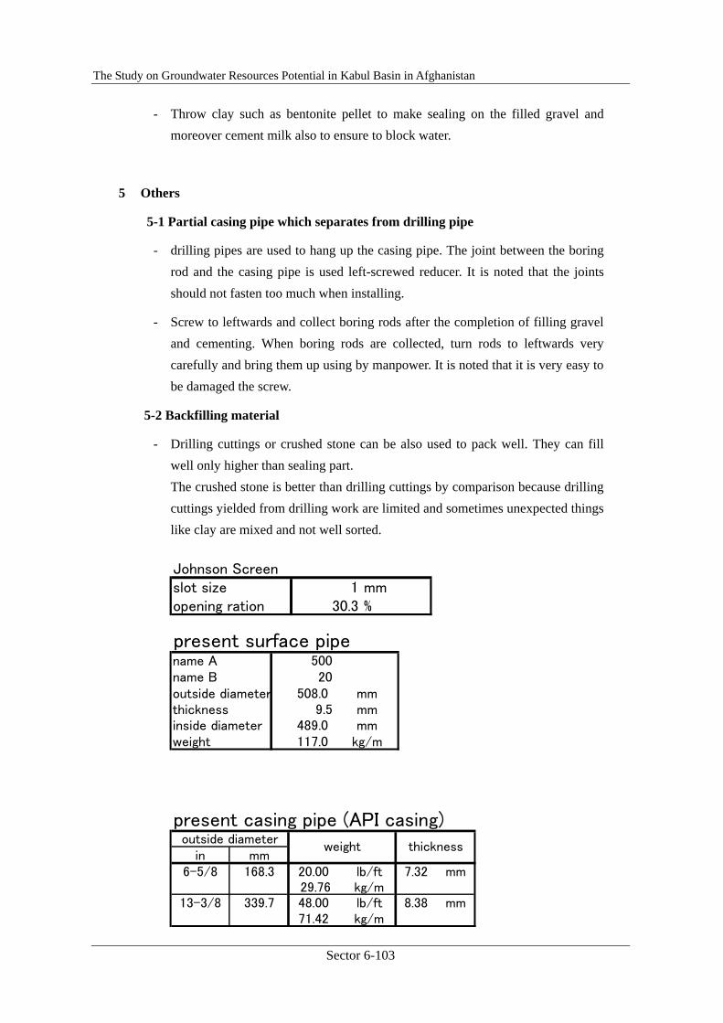
Johnson Screenslot size 1 mmopening ration 30.3 %
present surface pipename A 500name B 20outside diameter 508.0 mmthickness 9.5 mminside diameter 489.0 mmweight 117.0 kg/m
present casing pipe (API casing)
in mm6-5/8 168.3 20.00 lb/ft 7.32 mm
29.76 kg/m13-3/8 339.7 48.00 lb/ft 8.38 mm
71.42 kg/m
outside diameterweight thickness
- Throw clay such as bentonite pellet to make sealing on the filled gravel and moreover cement milk also to ensure to block water.
5 Others
5-1 Partial casing pipe which separates from drilling pipe
- drilling pipes are used to hang up the casing pipe. The joint between the boring rod and the casing pipe is used left-screwed reducer. It is noted that the joints should not fasten too much when installing.
- Screw to leftwards and collect boring rods after the completion of filling gravel and cementing. When boring rods are collected, turn rods to leftwards very carefully and bring them up using by manpower. It is noted that it is very easy to be damaged the screw.
5-2 Backfilling material
- Drilling cuttings or crushed stone can be also used to pack well. They can fill well only higher than sealing part. The crushed stone is better than drilling cuttings by comparison because drilling cuttings yielded from drilling work are limited and sometimes unexpected things like clay are mixed and not well sorted.
The Study on Groundwater Resources Potential in Kabul Basin in Afghanistan
Sector 6-104
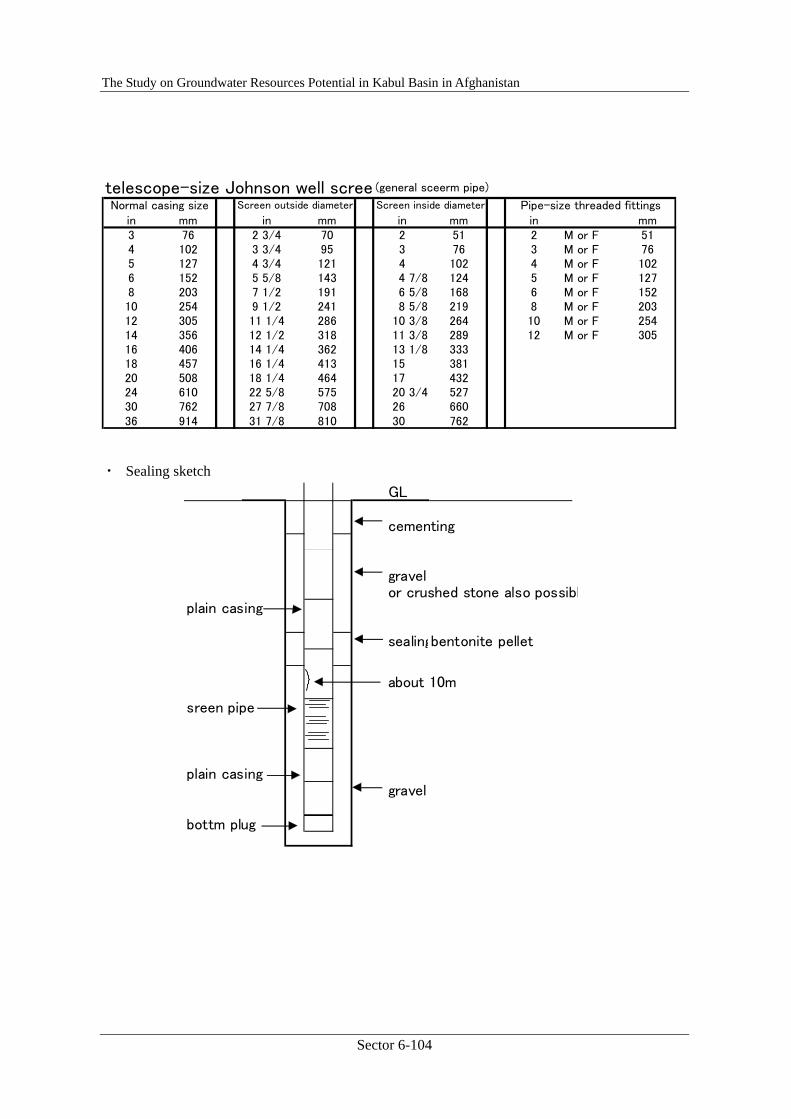
telescope-size Johnson well scree (general sceerm pipe)
in mm in mm in mm in mm3 76 2 3/4 70 2 51 2 M or F 514 102 3 3/4 95 3 76 3 M or F 765 127 4 3/4 121 4 102 4 M or F 1026 152 5 5/8 143 4 7/8 124 5 M or F 1278 203 7 1/2 191 6 5/8 168 6 M or F 15210 254 9 1/2 241 8 5/8 219 8 M or F 20312 305 11 1/4 286 10 3/8 264 10 M or F 25414 356 12 1/2 318 11 3/8 289 12 M or F 30516 406 14 1/4 362 13 1/8 33318 457 16 1/4 413 15 38120 508 18 1/4 464 17 43224 610 22 5/8 575 20 3/4 52730 762 27 7/8 708 26 66036 914 31 7/8 810 30 762
Screen outside diameter Screen inside diameter Pipe-size threaded fittingsNormal casing size
・ Sealing sketch GL
cementing
gravelor crushed stone also possibl
plain casing
sealingbentonite pellet
sreen pipe
plain casinggravel
bottm plug
about 10m
The Study on Groundwater Resources Potential in Kabul Basin in Afghanistan
Sector 6-105
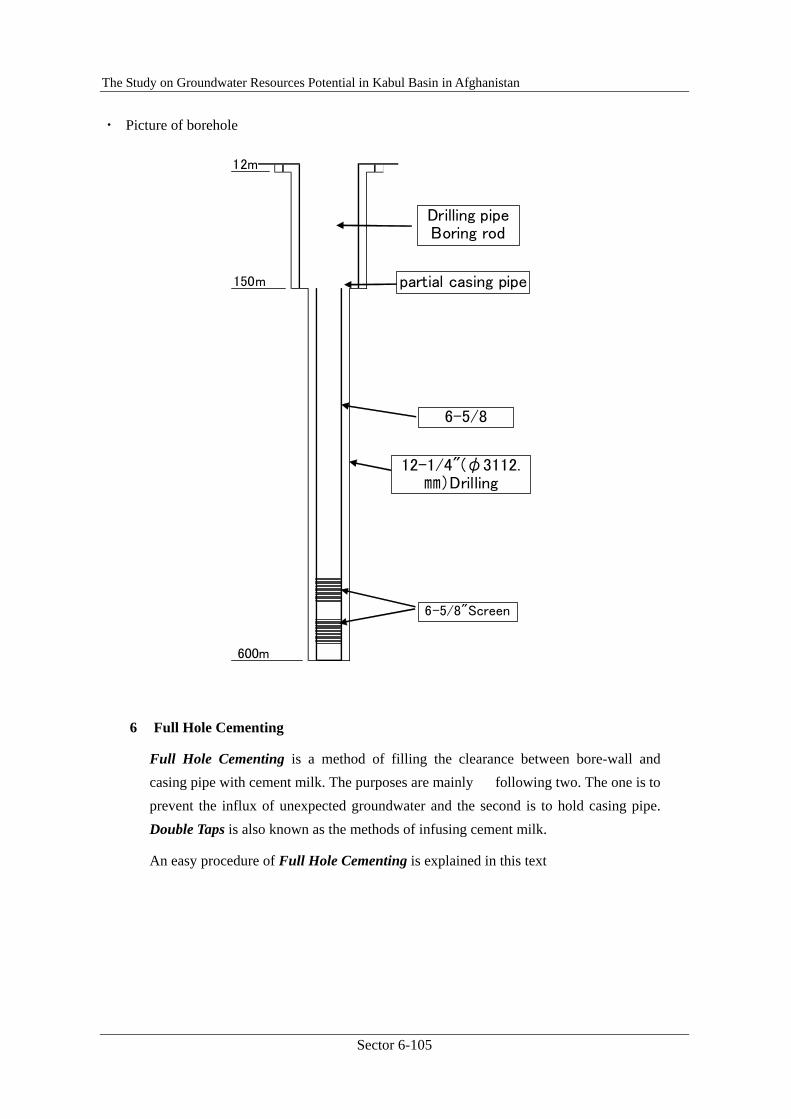
・ Picture of borehole
Drilling pipeBoring rod
局部ケーシング
6-5/8 Casing
12m
600m
150m
Drilling pipeBoring rod
partial casing pipe
6-5/8
12-1/4"(φ3112.㎜)Drilling
6-5/8"Screen
6 Full Hole Cementing
Full Hole Cementing is a method of filling the clearance between bore-wall and casing pipe with cement milk. The purposes are mainly following two. The one is to prevent the influx of unexpected groundwater and the second is to hold casing pipe. Double Taps is also known as the methods of infusing cement milk.
An easy procedure of Full Hole Cementing is explained in this text
The Study on Groundwater Resources Potential in Kabul Basin in Afghanistan
Sector 6-106
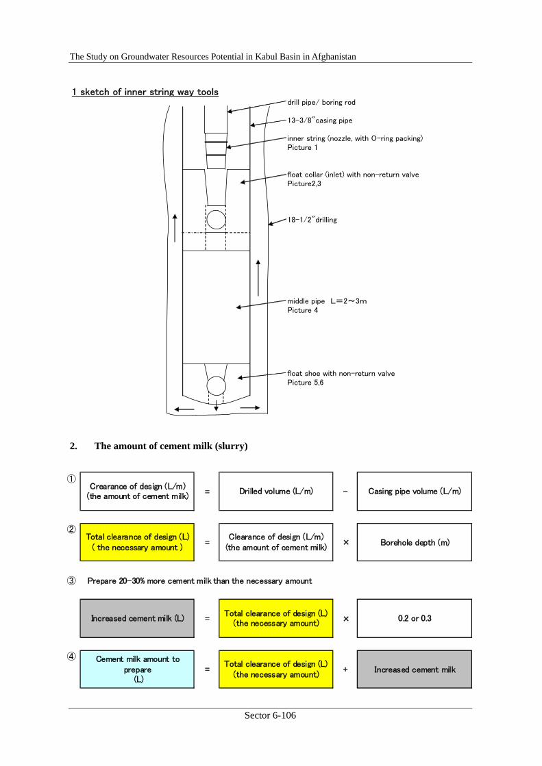
2. The amount of cement milk (slurry)
1 sketch of inner string way toolsdrill pipe/ boring rod
13-3/8"casing pipe
inner string (nozzle, with O-ring packing)Picture 1
float collar (inlet) with non-return valvePicture2,3
18-1/2"drilling
middle pipe L=2~3mPicture 4
float shoe with non-return valvePicture 5,6
①
= -
②
= ×
③ Prepare 20-30% more cement milk than the necessary amount
= ×
④
= +
Crearance of design (L/m)(the amount of cement milk)
Drilled volume (L/m) Casing pipe volume (L/m)
Total clearance of design (L)( the necessary amount )
Clearance of design (L/m)(the amount of cement milk)
Borehole depth (m)
Cement milk amount toprepare
(L)
Total clearance of design (L)(the necessary amount)
Increased cement milk
Increased cement milk (L)Total clearance of design (L)
(the necessary amount)0.2 or 0.3

The Study on Groundwater Resources Potential in Kabul Basin in Afghanistan
Sector 6-107
cement water
density kg/L 3.15 1
volume L/kg 0.32 1
Cement Water
1.0Kg + 0.68Kg 1.68Kg
=0.32L + 0.68L 1.0L
32 : 68 Cement and water are mixed in a ratio of 32:68.
3. The density of cement milk(slurry) (the normal density is 1.6-1.8)
The below is an example of the density of cement milk.
The density is set at 1.7 based on the right table.
Density
1.7 �
Ex) In the case, the total necessary cement milk amount is 1000L (1.0m3)
1,000L × 0.32 × 3.15 � 1,000kg
↑
1,000L × 0.68 = 680L
↑
The total necessary cement t
The density of cement
= × 32% × 3.15
Rate of cement at cement milk density 1.7
Total necessary cement(kg)
Cement milkamount to prepare
(L)
The total necessary water t
The Study on Groundwater Resources Potential in Kabul Basin in Afghanistan
Sector 6-108
4. The procedure of full hole cementing
1 Joint a float collar, a middle pipe and a float shoe with a casing pipe in order as shown in the sketch 1 and install it to borehole
2 Joint a water swivel with the casing pipe and circulate drilling fluid to clean the borehole after finishing the installation of the casing pipe
3 Joint a inner string with the drill pipe and install it into the casing pipe
4 Insert the inner string to the float collar and clear the borehole It is noted that the water level inside the casing should be measured to check whether water is leaking or not
5 Infuse the cement milk by a mud pump. At first, the pressure to infuse is lower than usual but it gradually increase as the cement milk comes up. Because the density of cement milk is heavier than the mud water’s one.
6 If the cement milk does not come out from the mouth of the borehole after infusing all the prepared cement, additional cement milk should be prepared and infused until coming up. But it must be judged by situation such as infusing pressure whether to continue infusing or not.
7 After finishing infusing cement milk, clean the inside of drill pipe by water for the
volume of the drill pipe and pull the inner string out from the float collar, then drill pipe as well.
The Study on Groundwater Resources Potential in Kabul Basin in Afghanistan
Sector 6-109
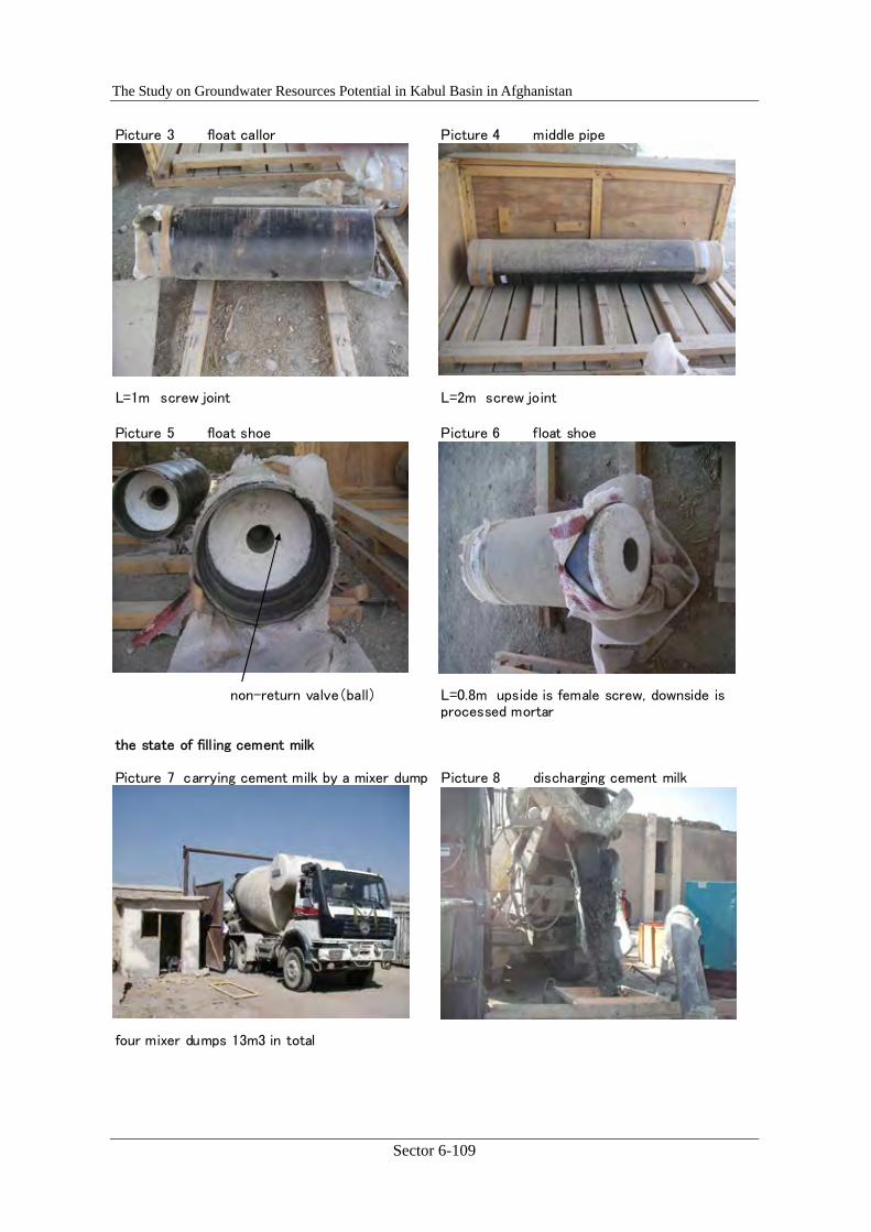
the state of fill ing cement milk
Picture 7 carrying cement milk by a mixer dump Picture 8 discharging cement milk
four mixer dumps 13m3 in total
Picture 3 float callor Picture 4 middle pipe
L=1m screw joint L=2m screw joint
Picture 5 float shoe Picture 6 float shoe
non-return valve(ball) L=0.8m upside is female screw, downside isprocessed mortar
The Study on Groundwater Resources Potential in Kabul Basin in Afghanistan
Sector 6-110
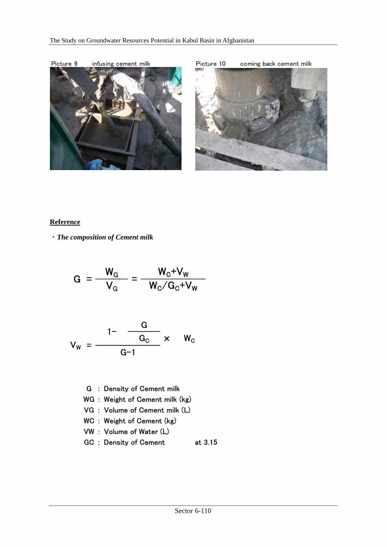
Picture 9 infusing cement milk Picture 10 coming back cement milk
Reference
・The composition of Cement milk
WG
VG==G
WC+VW
WC/GC+VW
G
GC × WCVW =
G-1
1-
G : Density of Cement milk
WG : Weight of Cement milk (kg)
VG : Volume of Cement milk (L)
WC : Weight of Cement (kg)
VW : Volume of Water (L)
GC : Density of Cement at 3.15
The Study on Groundwater Resources Potential in Kabul Basin in Afghanistan
Sector 6-111
2.5. Well Logging and Pumping Test
2.5.1. Well Logging, Main Text
JICA Training, Lecture Text ⑤-1 Aspect : WELL LOGGING
Contents
1. What is “Well Logging”......................................................................... 6-112
2. Logging and Casing Program ................................................................ 6-112
3. Major Geophysical Logging Methods ................................................... 6-112
3.1. Logging using electrical features ................................................... 6-112
3.2. Logging using radio activities........................................................ 6-115
3.3. Caliper Logging ............................................................................. 6-117
3.4. Other Logging................................................................................ 6-118
Sample of Logging..................................................................................... 6-120
The Study on Groundwater Resources Potential in Kabul Basin in Afghanistan
Sector 6-112
1. What is “Well Logging”
Well logging, also known as borehole logging is the practice of making a detailed record (log) of the geologic formations penetrated by a borehole or well. The log may be based either on visual inspection of samples brought to the surface (geological logs) or on physical measurements made by instruments lowered into the hole (geophysical logs). Well logging is done when drilling boreholes for groundwater, oil and gas, minerals, and for environmental and geotechnical studies. This technical transfer seminar concerns to the latter; on geophysical logging.
2. Logging and Casing Program
As mentioned above, the most of well or borehole logging aims to obtain detail geological and/or hydro-geological information of the hole penetrating, however, well logging for groundwater has another very important role that it shall be a base of casing program. In the case of well drilling, it is quite important to install screen and casing pipes at proper portions immediately after the drilling completion. And to design a screen plan (casing program), usually the well logging is the most simple and strong tool, because it can offer hydro-geological information to distinguish aquifer(s) from aquitard and aquiclude.
3. Major Geophysical Logging Methods
Depending upon the physical properties it applies, there several kinds of geophysical logging methods. Those physical properties are electrical features, radio activities, borehole diameter, elastic feature, temperature, and so on.
3.1. Logging using electrical features
Well logging using electrical features of strata of the well, simply called as “Electric Logging”, is one of the most common and effective logging methods, because electrical properties of aquifer and aquiclude are usually different enough to be detected by rather simple instruments. Electric logging is roughly divided into two categories; “Resistivity Logging” and “SP Logging”.
Resistivity Logging
As the name indicates, it is the method to know electric resistivity of the strata surrounding the well continuously. Within an uncased well, current and potential electrodes can be lowered to measure electric resistivities of the surrounding media and to obtain a trace of their variation with depth. The result is a resistivity log. Such a log is affected by fluid within a well, by well diameter, by the character of surrounding strata, and by groundwater.
The Study on Groundwater Resources Potential in Kabul Basin in Afghanistan
Sector 6-113
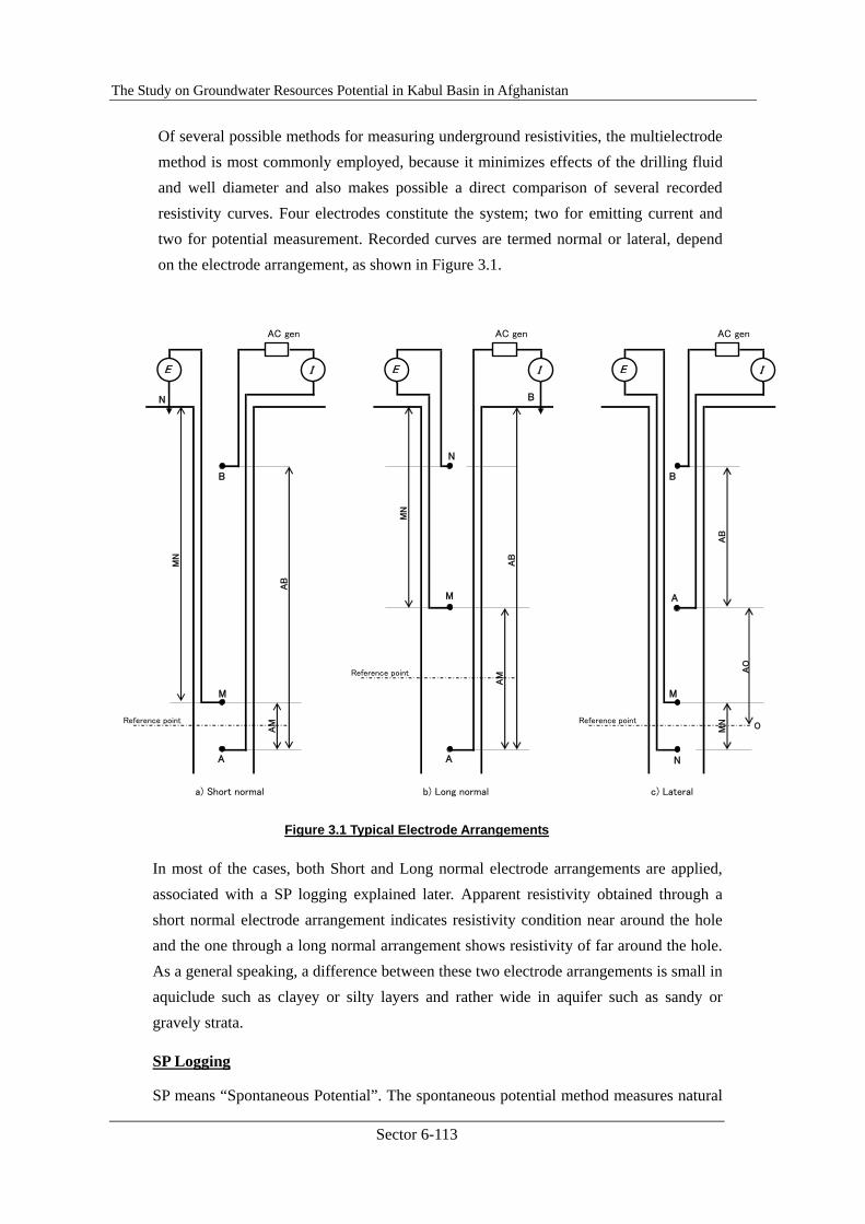
Of several possible methods for measuring underground resistivities, the multielectrode method is most commonly employed, because it minimizes effects of the drilling fluid and well diameter and also makes possible a direct comparison of several recorded resistivity curves. Four electrodes constitute the system; two for emitting current and two for potential measurement. Recorded curves are termed normal or lateral, depend on the electrode arrangement, as shown in Figure 3.1.
AC gen AC gen AC gen
Reference point
Reference point Reference point
a) Short normal b) Long normal c) Lateral
AO
AB
MN
MN
AB
AM
AM
MN
AB
E I
A
M
B
N
E I
A
M
B
N
E I
A
M
B
N
O
Figure 3.1 Typical Electrode Arrangements
In most of the cases, both Short and Long normal electrode arrangements are applied, associated with a SP logging explained later. Apparent resistivity obtained through a short normal electrode arrangement indicates resistivity condition near around the hole and the one through a long normal arrangement shows resistivity of far around the hole. As a general speaking, a difference between these two electrode arrangements is small in aquiclude such as clayey or silty layers and rather wide in aquifer such as sandy or gravely strata.
SP Logging
SP means “Spontaneous Potential”. The spontaneous potential method measures natural

The Study on Groundwater Resources Potential in Kabul Basin in Afghanistan
Sector 6-114
electrical potentials found within the earth. Measurements, usually in millivolts, are obtained from a recording potentiometer connected to two electrodes. One electrode is lowered in an uncased well and the others is connected to the ground surface, as illustrated by electrodes M and N in Fig 3.1. a). The potentials are primarily produced by electrochemical cells formed by the electrical conductivity difference of drilling mud and groundwater where boundaries of permeable zones intersect a well or borehole.
Potential values range from zero to several hundred millivolts. By convention potential logs are read in terms of positive and negative deflections from an arbitrary baseline, usually associated with an impermeable formation of considerable thickness. The sign of the potential depends on the ratio of the salinity (or resistivity) of the drilling mud to the formation water.
In practice, potential and resistivity logs are usually recorded together as shown in Figure 3.2. The two logs often indicate the same subsurface conditions and thereby supplement each other; however, occasionally the two types of logs will furnish information not available directly from either alone.

The Study on Groundwater Resources Potential in Kabul Basin in Afghanistan
Sector 6-115
3.2. Logging using radio activities
Radiation logging, also known as nuclear or radioactive logging, involves the measurement of fundamental particles emitted from unstable radioactive isotopes. Logs having application to groundwater are natural gamma, gamma-gamma, and neutron; these are promising but not widely used hydrogeologic tools. An Important advantage of these logs over most others is that they may be recorded in either cased or open holes that are filled with any fluid.
Natural-Gamma Logging
Because all rocks emit natural-gamma radiation, a record of this constitutes a natural-gamma log. The radiation originates from unstable isotopes of potassium, uranium, and thorium. In general, the natural-gamma activity of clayey formations is significantly higher than that of quartz sands and carbonate rocks. The most important application to groundwater hydrology is identification of lithology, particularly clayey or shale-bearing sediments, which possess the highest gamma intensity. Because most of the gamma rays detected originate within 15-30 cm of the borehole wall, logs run before and after well development can reveal zones where clay and fine-grained material were removed.
Figure 3.3 shows the natural-gamma log of a test hole in unconsolidated sediments together with its geologic interpretation.

The Study on Groundwater Resources Potential in Kabul Basin in Afghanistan
Sector 6-116
Figure 3.3 Natural-gamma log of a test hole in Moraine City, Ohio.
Gamma-Gamma Logging
Gamma radiation originating from a source probe and recorded after it is backscattered and attenuated within the borehole and surrounding formation constitutes a gamma-gamma log. The source probe generally contains cobalt-60 or cesium-137, which is shielded from a sodium iodide detector built into the probe.
Primary application of gamma-gamma logs are for identification of lithology and measurement of bulk density and porosity of rocks.
The Study on Groundwater Resources Potential in Kabul Basin in Afghanistan
Sector 6-117
Neutron Logging
Neutron logging is accomplished by a neutron source and detector arranged in a single probe, which produces a record related to the hydrogen content of the borehole environment. In most formations the hydrogen content is directly proportional to the interstitial water; therefore, neutron logs can measure moisture content above the water table and porosity below the water table.
3.3. Caliper Logging
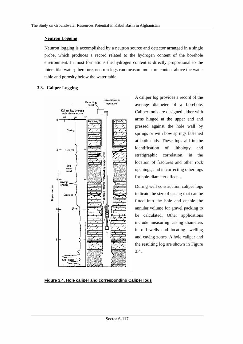
A caliper log provides a record of the average diameter of a borehole. Caliper tools are designed either with arms hinged at the upper end and pressed against the hole wall by springs or with bow springs fastened at both ends. These logs aid in the identification of lithology and stratigraphic correlation, in the location of fractures and other rock openings, and in correcting other logs for hole-diameter effects.
During well construction caliper logs indicate the size of casing that can be fitted into the hole and enable the annular volume for gravel packing to be calculated. Other applications include measuring casing diameters in old wells and locating swelling and caving zones. A hole caliper and the resulting log are shown in Figure 3.4.
Figure 3.4. Hole caliper and corresponding Caliper logs
The Study on Groundwater Resources Potential in Kabul Basin in Afghanistan
Sector 6-118
3.4. Other Logging
Although they are not so popular in the field of groundwater investigation, there are several other logging techniques. Some of those are roughly explained.
Temperature Logging
A vertical traverse measurement of groundwater temperature in a well can be readily obtained with a recording resistance thermometer. Such data can be of value in analyzing subsurface conditions. Ordinarily, temperatures will increase with depth in accordance with the geothermal gradient, amounting to roughly 3� for each 100m in depth. Departures from this normal gradient may provide information on circulation or geologic conditions in the well.
Abnormally cold temperatures may indicate the presence of gas or, in deep wells, may suggest recharge from ground surface. Likewise, abnormally warm water may occur from water of deep-seated origin. Temperatures may indicate waters from different aquifers intersected by a well. In a few instances temperature logs have aided the location of the approximate top of new concrete behind a casing, because the heat generated during setting produces a marked temperature increase of the water within the casing.
Fluid-Condition Logging
A continuous record of the conductivity of fluid in a borehole is a fluid-condition log. The probe measures the AC-voltage drop across two closely spaced electrodes and is governed by the resistivity of the fluid between the electrodes. Fluid resistivity is generally measured in ohm-m; its reciprocal, conductivity, is measured in μS/cm. Use of the term of fluid-conductivity log avoids confusion with a resistivity log, which measures rock and fluid conditions outside a borehole.
Fluid-conductivity logs enable saline water zones to be located, furnish information on fluid flow within a well, and provide a means to extrapolate water-sample data from a well.
Fluid-Velocity Logging
Measurement of fluid movement within a borehole constitutes a fluid-velocity log. Such data reveal strata contributing water to a well, flow from one stratum to another within a well, hydraulic difference between aquifers intersected by a well, and casing leaks.

The Study on Groundwater Resources Potential in Kabul Basin in Afghanistan
Sector 6-119
Acoustic Logging
Acoustic, or sonic, logging measures the velocity of sound through the rock surrounding an uncased, fluid-filled hole. Sound velocity in rock is governed by the velocity of the rock matrix and the fluid filling the pore space; therefore, the greater porosity, the closer the measured sound velocity approaches that of the fluid.
Chief applications of the acoustic log include determining the depth and thickness of porous zones, estimating porosity, identifying fracture zones, and determining the bounding of cement between the casing and the formation.
Television Logging (Borehole Camera)
A convenient tool with increasing use is a television camera lowered in a well. Specially designed wide-angle cameras, typically less than 7 cm in diameter, are equipped with light and provide continuous visual inspection of a borehole; with videotape a record of the interior can be preserved.
Among the variety of applications are locating changes in geologic strata, pinpointing large pore spaces, inspecting the condition of well casing and screen, checking for debris in wells, locating zones of sand entrance, and searching for lost drilling tools.
The Study on Groundwater Resources Potential in Kabul Basin in Afghanistan
Sector 6-120
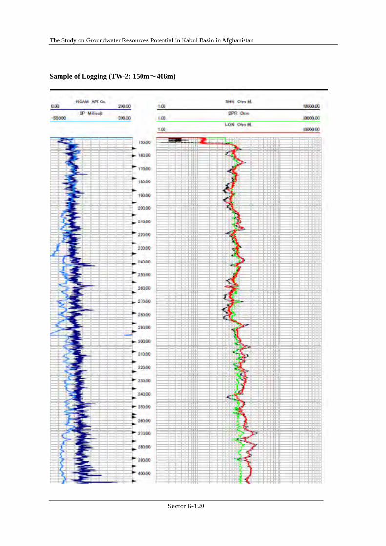
Sample of Logging (TW-2: 150m~406m)

The Study on Groundwater Resources Potential in Kabul Basin in Afghanistan
Sector 6-121
(cont. 406m~554m)
The Study on Groundwater Resources Potential in Kabul Basin in Afghanistan
Sector 6-122
2.5.2. Pumping Test, Main Text
JICA Training Lecture Text ⑤-2
Aspect : PUMPING TEST
Contents
1. Pumping Test General ................................................................................6-123
2. Preliminary Test..........................................................................................6-124
3. Step Drawdown Test...................................................................................6-125
4. Constant Discharge Test .............................................................................6-129
5. Recovery Test .............................................................................................6-131
6. In-situ Test and Water Sampling for Water Quality Analysis .....................6-133
7. Technical Specifications .............................................................................6-134
7.1. PUMPING TEST.................................................................................6-134
7.1.1. Equipment and devices................................................................6-134
7.1.2. Preliminary Test...........................................................................6-134
7.1.3. Step-drawdown Test ....................................................................6-134
7.1.4. Constant Discharge Test and Recovery Test................................6-135
7.1.5. Test Record..................................................................................6-135
7.1.6. Water Quality Analysis................................................................6-135
The Study on Groundwater Resources Potential in Kabul Basin in Afghanistan
Sector 6-123
1. Pumping Test General
A pumping test is a way of obtaining information about groundwater systems and the bores which tap them1. The test is based on a period of pumping during which the pumping rate (discharge), water level in the bore, and elapsed time are measured. The test can assess the behaviour of the bore, which will help you to:
- predict the performance under different pumping regimes, - determine the optimum pumping schedules, - determine the most suitable pump and intake depth, - determine water quality changes in time and discharge.
When water is pumped from a borehole (well), the head in the borehole is lowered, creating a drawdown and setting up a localized hydraulic gradient which causes water to flow from the aquifer to the borehole. The head of the aquifer is also reduced and the effect spreads outwards from the borehole. A "cone of depression" in the potentiometric surface is thus formed around the borehole, the shape and manner of the expansion of this cone depends on the pumping rate and on the hydraulic properties of the aquifer. By measuring the changes in water level in the borehole over time it is possible to assess the quantitative characteristics of both the borehole and the aquifer.
In “Wikipedia”, the most famous free encyclopedia in the Internet2, “Aquifer Test” is defined as follows: An aquifer test (or a pumping test) is conducted to evaluate an aquifer by “stimulating” the aquifer through constant pumping, and observing the aquifer’s “response” (drawdown) in observation wells. Aquifer testing is a common tool that hydrogeologists use to characterize a system of aquifers, aquitards and flow system boundaries.
However, “Pumping test” is a generic name of a series (or stages) of tests; consisted of preliminary, step drawdown, constant discharge, and recovery tests.
1 http://www.dse.vic.gov.au/CA256F310024B628/0/E1E29FA57AB35667CA256FF200214709/$File/GWNOTE11.pdf 2 http://en.wikipedia.org/wiki/Well_test
The Study on Groundwater Resources Potential in Kabul Basin in Afghanistan
Sector 6-124
2. Preliminary Test
A series of Pumping Test is started by a preliminary procedure called as “Preliminary Test”. There are two major purposes of the Preliminary Test. One is to confirm the total pumping system for the test such as; power supply system, all pipes connection, setting and connection of pump, flow-rate measuring system, drainage system, water level measuring system, and so on. The others is to know the relation of pumping rate drawdown roughly to examine the pumping rates in following “Step Drawdown Test” and to determine the pump for following tests.
Procedures of the preliminary test are quite simple; at first, inserting any submergible pump with (supposed to be) proper discharge capacity in the test well, and connecting all delivery pipes and measuring system as well as drainage system then, start pumping by normal (moderate) power. Depth of the pump installation should be determined in advance considering the depth of pump-housing and water level measuring device. Since immediately after the pumping start, the discharge rate and groundwater level (drawdown) in the test well must be checked carefully. If the drawdown is too small or too large in comparison with the pump installed or pump housing, even though under the highest or the lowest power supplies, the pump shall be replace to the other one with proper pumping capacity. When the drawdown is in the acceptable range of depth, the pumping rate should be changed raising or reducing several times, to know the highest and the lowest pumping rates by which the smallest and largest drawdown are stably available.
Based on the results of preliminary test, the submersible pump to be used for the test and each pumping step in the step drawdown test shall be determined.
The Study on Groundwater Resources Potential in Kabul Basin in Afghanistan
Sector 6-125
3. Step Drawdown Test
Step drawdown test is, as the name shows, to pump up groundwater by several pumping rates (pumping steps) and to know the relation between the pumping rates and the drawdown. Purposes of the step drawdown test are to determine the pumping rate to be applied in the following “Constant Discharge Test” principally, and to analyze a well efficiency.
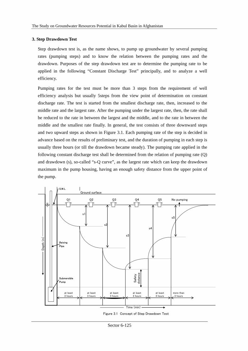
Pumping rates for the test must be more than 3 steps from the requirement of well efficiency analysis but usually 5steps from the view point of determination on constant discharge rate. The test is started from the smallest discharge rate, then, increased to the middle rate and the largest rate. After the pumping under the largest rate, then, the rate shall be reduced to the rate in between the largest and the middle, and to the rate in between the middle and the smallest rate finally. In general, the test consists of three downward steps and two upward steps as shown in Figure 3.1. Each pumping rate of the step is decided in advance based on the results of preliminary test, and the duration of pumping in each step is usually three hours (or till the drawdown became steady). The pumping rate applied in the following constant discharge test shall be determined from the relation of pumping rate (Q) and drawdown (s), so-called “s-Q curve”, as the largest rate which can keep the drawdown maximum in the pump housing, having an enough safety distance from the upper point of the pump.
S.W.L
Ground surface
Q1 Q2 Q3 Q4 Q5 No pumping
s1s5
s2s4
s3
Raising
Pipe
Submersible
Pump
at least at least at least at least at least more than3 hours 3 hours 3 hours 3 hours 3 hours 3 hours
Time (min)
Figure 3.1 Concept of Step Drawdown Test
Dept
h (m
)
Saf
ety
dist
ance

The Study on Groundwater Resources Potential in Kabul Basin in Afghanistan
Sector 6-126
The drawdown in a pumped well consists of two components: the aquifer losses and the well losses (Figure 3.2)3. Aquifer losses are the head losses that occur in the aquifer where the flow is laminar. They are time-dependent and vary linearly with the well discharge.
Figure 3.2 Water Losses in Well
The drawdown s1 corresponding to this linear aquifer loss can be expressed as
S1 = B1(rw,t)Q
where B1 is the linear aquifer loss coefficient in d/m2 and r, is the effective radius of the well. This coefficient can be calculated from the well-flow equations. For confined aquifers for example, it can be expressed as
B1(rw,t) = w(u)/4πKH
3 http://www2.alterra.wur.nl/Internet/webdocs/ilri-publicaties/publicaties/Pub57/pub57-h5.pdf
The Study on Groundwater Resources Potential in Kabul Basin in Afghanistan
Sector 6-127
where u = (rw2S)/(4KHt). From the results of aquifer-test analyses, the values for transmissivity KH and storativity S can be used to calculate BI values as function of rw, and t.
Well losses are divided into linear and non-linear head losses. Linear well losses are caused by the aquifer being damaged during the drilling and completion of the well. They comprise, for example, head losses resulting from the aquifer material compacting during drilling; head losses resulting from the aquifer becoming plugged with drilling mud, which reduces the permeability near the bore hole; head losses in the gravel pack; and head losses .in the screen. The drawdown s2 corresponding to linear well losses can be expressed as
S2 = B2Q
where B2 is the linear well loss coefficient in d/m2. The non-linear well losses include the friction losses that occur inside the well screen and in the suction pipe where the flow is turbulent, and head losses that occur in the zone adjacent to the well where the flow is also usually turbulent. The drawdown s3 corresponding to these non-linear well losses can be expressed as
s3 = CQp
where C is the non-linear well loss coefficient in dP/m3P-l, and P is an exponent. The general equation describing the drawdown in a pumped well as function of aquifer/well losses and discharge thus reads
sw = s1 + s2 + s3 = (B1 + B2) Q + CQp = BQ + CQp
Jacob (1947) used a constant value of 2 for the exponent P. According to Lennox (1966) the value of P can vary between 1.5 and 3.5. Our experience is that in fractured rock aquifers its value may even exceed 3.5. The value of P = 2 as proposed by Jacob is, however, still widely accepted. The values of the three parameters B, C and P in Equation 5.4 can be found from the analysis of step-drawdown tests. Note that B represents the contribution of the aquifer loss plus the linear well loss; their individual contributions can only be determined from a combination of step-drawdown and aquifer test analyses.
The relationship between drawdown and discharge can be expressed as the specific capacity of a well, Q/sw, which describes the productivity of both the aquifer and the well. The specific capacity decreases as pumping continues and also with increasing Q. The well efficiency, Ew, is defined as the ratio of the aquifer head loss to the total head losses; when expressed as a percentage it reads
Ew = 100B1Q/(BQ+CQP)
The well efficiency according to the above Equation can be assessed if the results of a step-drawdown and of an aquifer test are available. The former are needed for the values of
The Study on Groundwater Resources Potential in Kabul Basin in Afghanistan
Sector 6-128
B, C and P and the latter for the value of Bl.
If only the results of a step-drawdown tests are available, the substitution of the B value into above Equation for the B1 value will overestimate the well efficiency, because B > B1. For these cases, Driscoll(1986) introduced another parameter, Lp, being the ratio of the laminar head loss to the total head losses; when expressed as a percentage it reads
Lp = 100BQ/(BQ+CQP)
Above Equation can be used to analyze the well performance yearly, because step-drawdown tests are usually conducted as single-well tests, i.e. the drawdown is not observed in any piezometer.

The Study on Groundwater Resources Potential in Kabul Basin in Afghanistan
Sector 6-129
4. Constant Discharge Test
Constant discharge test is the main flame of the pumping test. As the name indicates, it is the test to pump up groundwater in a certain rate for rather long period, until the drawdown became enough steady. The constant discharge rate should be determined based on the results of step drawdown test, as large as possible but enough safety. Duration of the constant discharging is usually 2 day (24 hours) or 3 days (72 hours) continuously. One important notice on the constant discharge test is that it must be started after the groundwater level in the test well has been recovered completely to the static water level measured before the commencement of any pumping test. Another important note is that the test needs any (at least one of) observation well near around the test well to analyze the result of the test. Observation well should be drilled at the point apart from the test well for 20 to 50 m in accordance with the surrounding hydro-geological condition, and to the depth almost same with the test well. Sole well constant discharge test can offer simply a specific yield and a Transmissivity (T) can be analyzed but a Storativity (S), another important aquifer constant, can not be analyzed.
There are several analyzing methods or techniques on the constant discharge test. Followings are one of introduction on an analysis of the test, served by Wikipedia.
An appropriate model or solution to the groundwater flow equation must be chosen to fit to the observed data. There are many different choices of models, depending on what factors are deemed important including:
- leaky aquitards, - unconfined flow (delayed yield), - partial penetration of the pumping and monitoring wells, - finite wellbore radius — which can lead to wellbore storage, - dual porosity (typically in fractured rock), - anisotropic aquifers, - heterogeneous aquifers, - finite aquifers (the effects of physical boundaries are seen in the test), and - combinations of the above situations.
Nearly all aquifer test solution methods are based on the Theis solution; it is built upon the most simplifying assumptions. Other methods relax one or more of the assumptions the Theis solution is built on, and therefore they get a more flexible (and more complex) result.
The Study on Groundwater Resources Potential in Kabul Basin in Afghanistan
Sector 6-130
Transient Theis solution
The Theis equation was adopted by Charles Vernon Theis (working for the US Geological Survey) in 1935[1], from heat transfer literature (with the mathematical help of C.I. Lubin), for two-dimensional radial flow to a point source in an infinite, homogeneous aquifer. It is simply
where s is the drawdown (change in hydraulic head at a point since the beginning of the test), u is a dimensionless time parameter, Q is the discharge (pumping) rate of the well (volume divided by time, or m³/s), T and S are the transmissivity and storativity of the aquifer around the well (m²/s and unitless), r is the distance from the pumping well to the point where the drawdown was observed (m or ft), t is the time since pumping began (minutes or seconds), and W(u) is the "Well function" (called the exponential integral, E1, in non-hydrogeology literature).
Typically this equation is used to find the average T and S values near a pumping well, from drawdown (hydrology) data collected during an aquifer test. This is a simple form of inverse modeling, since the result (s) is measured in the well, r, t, and Q are observed, and values of T and S which best reproduce the measured data are put into the equation until a best fit between the observed data and the analytic solution is found. As long as none of the additional simplifications which the Theis solution requires (in addition to those required by the groundwater flow equation) are violated, the solution should be very good.
The assumptions required by the Theis solution are:
- homogeneous, isotropic, confined aquifer, - well is fully penetrating (open to the entire thickness (b) of aquifer), - the well has zero radius (it is approximated as a vertical line) — therefore no water
can be stored in the well, - aquifer is infinite in radial extent, - horizontal (not sloping), flat, impermeable (non-leaky) top and bottom boundaries of
aquifer,

The Study on Groundwater Resources Potential in Kabul Basin in Afghanistan
Sector 6-131
Even though these assumptions are rarely all met, depending on the degree to which they are violated (e.g., if the boundaries of the aquifer are well beyond the part of the aquifer which will be tested by the pumping test) the solution may still be useful.
Steady-state Thiem solution
Steady-state radial flow to a pumping well is commonly called the Thiem solution, it comes about from application of Darcy's law to cylindrical shell control volumes (i.e., a cylinder with a larger radius which has a smaller radius cylinder cut out of it) about the pumping well; it is commonly written as:
In this expression h0 is the background hydraulic head, h-h0 is the drawdown at the radial distance r from the pumping well, Q is the discharge rate of the pumping well (at the origin), T is the transmissivity, and R is the radius of influence, or the distance at which the head is still h0. These conditions (steady-state flow to a pumping well with no nearby boundaries) never truly occur in nature, but it can often be used as an approximation to actual conditions; the solution is derived by assuming there is a circular constant head boundary (e.g., a lake or river in full contact with the aquifer) surrounding the pumping well at a distance R.
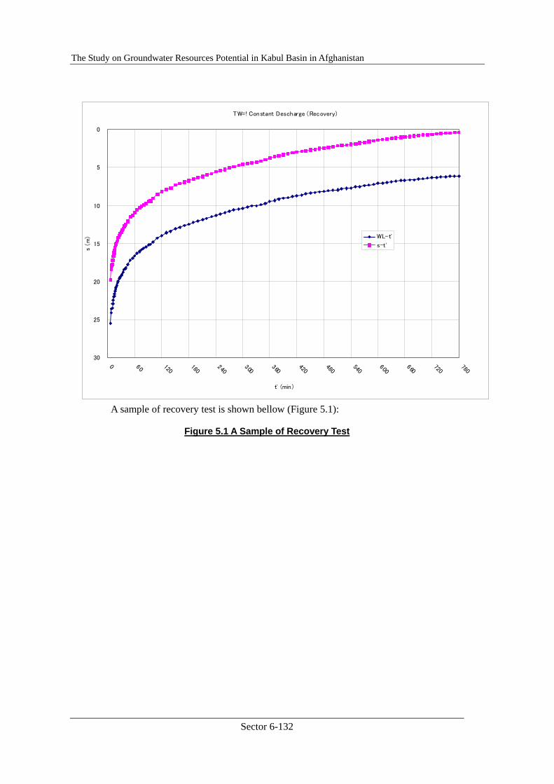
5. Recovery Test
The final procedure in a series of pumping test is “Recovery Test”. This is, however, a necessary procedure after the completion of constant discharge test; to stop pumping and measure recovering groundwater level until it reached to the original static water revel.
The Study on Groundwater Resources Potential in Kabul Basin in Afghanistan
Sector 6-132
A sample of recovery test is shown bellow (Figure 5.1):
Figure 5.1 A Sample of Recovery Test
TW=! Constant Descharge (Recovery)
0
5
10
15
20
25
300 60 120
180240
300360
420480
540600
660720
780
t' (min)
s (
m) WL-t'
s-t'
The Study on Groundwater Resources Potential in Kabul Basin in Afghanistan
Sector 6-133
6. In-situ Test and Water Sampling for Water Quality Analysis
To know a groundwater quality and a yielding condition of the test well, it is recommended to conduct in-situ water quality tests during every pumping test. Items of the in-situ tests are usually three; water temperature, pH, and EC value of the groundwater. In-situ water quality test shall be done, at least, once in the preliminary test period, in each pumping step during the step drawdown test, and four times a day during the constant discharge test.
Besides the in-situ test, the pumped groundwater shall be taken for a laboratory water quality analysis, in the last stretch of the constant discharge test. Just at the sampling time, in-situ water quality test must be done simultaneously. Items to be analyzed in the laboratory are depending upon the characteristics or purpose of the project. In this JICA Project, following items of water qualities are conducted:
- Physical properties; Turbidity, Color, EC, pH, Temperature(in situ) - Ionic Concentration; Na, K, Mg, Ca, T-Fe, Mn, CO2, HCO3, NH3, NO2-N, NO3-N, Cl,
SO4, F, As - Bacteria; Coliforms, Fecal coliforms, Common bacteria
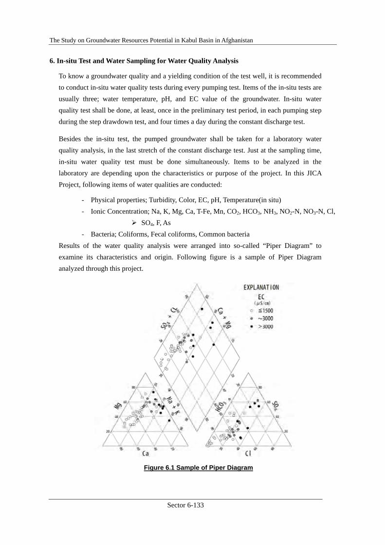
Results of the water quality analysis were arranged into so-called “Piper Diagram” to examine its characteristics and origin. Following figure is a sample of Piper Diagram analyzed through this project.
Figure 6.1 Sample of Piper Diagram
The Study on Groundwater Resources Potential in Kabul Basin in Afghanistan
Sector 6-134
7. Technical Specifications
Followings are a sample of technical specification on Pumping Test.
7.1. PUMPING TEST
7.1.1. Equipment and devices
The Contractor shall provide a proper pump and its attachment to be utilized for the pumping test. The type, name, capacity, and its specification shall be noticed to the Engineer for his approval prior to carry it to the site.
For measurement of discharge, the Contractor shall provide a calibrated wear, orifice or venture meter and/or accurate associated piezometer.
Water level in the well shall be measured by electric detective devices.
The pumped water shall be led and released at the position enough far from the teat well, not to disturb the test by re-infiltration, by proper conduit or through other suitable means.
7.1.2. Preliminary Test
After setting of all equipment and devices, the pumping equipment shall be calibrated at various pumping rates in order to ensure that all the equipment are properly functioning and to select the pumping rate for the subsequent step-drawdown test, the drawdown and yield shall be presumed through the test.
The pumping rate shall be modified according to the drawdown at the pumping well, and the preliminary pumping shall be continued at least four (4) hours.
The static water level of both pumping and observatory well (if exist) shall be measured carefully before any pumping, and the tests described below shall be started after the water level recovered to the original water level.
7.1.3. Step-drawdown Test
The borehole shall be pumped continuously at least three (3) increasing and two (2) decreasing discharge rates, maintaining each rate at a water level to be stable, but at least more than 180 minutes.
The pumping rate of each step shall be instructed by the Engineer based on the result of preliminary test.
For each pumping discharge, the water level at the borehole shall be measured and recorded in the manner shown below;
Period Interval of recording
0 – 5 min. 30 sec.
5 – 15 min. 1 min.
15 – 30 min. 5 min.
The Study on Groundwater Resources Potential in Kabul Basin in Afghanistan
Sector 6-135
30 – 90 min. 10 min.
after 360 min. 30 min.
7.1.4. Constant Discharge Test and Recovery Test
Pumping shall be continued at least 72 hours without any interruption. The constant discharge rate shall be instructed by the Engineer.
Water level of the borehole shall be measured and recorded during full pumping and recovery period. The measurement of recovery can be stopped when the recovery attains to the static water level.
The water level shall be measured and recorded as following time interval;
Period Interval of recording
0 – 5 min. 30 sec.
5 – 15 min. 1 min.
15 – 30 min. 5 min.
30 – 180 min. 15 min.
180 – 360 min. 30 min.
360 – 900 min. 60 min.
after 900 min. 120 min.
7.1.5. Test Record
The Contractor shall submit the pumping test records, in a proper forms of hard-printed and floppy-disk-base approved by the Engineer, within three (3) days after the completion of any pumping test to the Engineer.
7.1.6. Water Quality Analysis
The Engineer shall make a series of in-situ water quality test of water temperature, pH, and EC, and take water sample for laboratory water quality analysis, during the constant discharge test.
The Contractor shall assist the Engineer for the test and sampling as per his request. No extra payment shall be made to the Contractor for the assistance during the test and sampling.
The Study on Groundwater Resources Potential in Kabul Basin in Afghanistan
Sector 6-136
2.5.3. Pumping Test, Analysis
JICA Training Lecture Text ⑤-2 (cont.)
Aspect : PUMPING TEST ANALYSIS
Contents
1. DEFINITION OF TERMS ...............................................................................6-137
2. CONSTANT DISCHARGE TEST...................................................................6-140
2.1. Equilibrium Well Equation.........................................................................6-140
2.2. Non-equilibrium Well Equation .................................................................6-143
2.3. Modified Non-equilibrium Equation..........................................................6-146
2.4. Recovery Test .............................................................................................6-149
3. STEP DRAW-DOWN TEST ............................................................................6-152
The Study on Groundwater Resources Potential in Kabul Basin in Afghanistan
Sector 6-137
1. DEFINITION OF TERMS
It is important to understand clearly the meaning of common terms related to pumping wells.
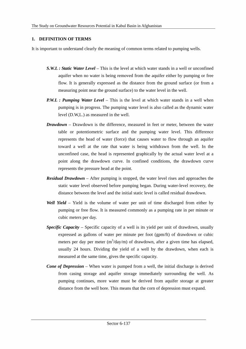
S.W.L : Static Water Level – This is the level at which water stands in a well or unconfined aquifer when no water is being removed from the aquifer either by pumping or free flow. It is generally expressed as the distance from the ground surface (or from a measuring point near the ground surface) to the water level in the well.
P.W.L : Pumping Water Level – This is the level at which water stands in a well when pumping is in progress. The pumping water level is also called as the dynamic water level (D.W,L.) as measured in the well.
Drawdown – Drawdown is the difference, measured in feet or meter, between the water table or potentiometric surface and the pumping water level. This difference represents the head of water (force) that causes water to flow through an aquifer toward a well at the rate that water is being withdrawn from the well. In the unconfined case, the head is represented graphically by the actual water level at a point along the drawdown curve. In confined conditions, the drawdown curve represents the pressure head at the point.
Residual Drawdown – After pumping is stopped, the water level rises and approaches the static water level observed before pumping began. During water-level recovery, the distance between the level and the initial static level is called residual drawdown.
Well Yield – Yield is the volume of water per unit of time discharged from either by pumping or free flow. It is measured commonly as a pumping rate in per minute or cubic meters per day.
Specific Capacity – Specific capacity of a well is its yield per unit of drawdown, usually expressed as gallons of water per minute per foot (gpm/ft) of drawdown or cubic meters per day per meter (m3/day/m) of drawdown, after a given time has elapsed, usually 24 hours. Dividing the yield of a well by the drawdown, when each is measured at the same time, gives the specific capacity.
Cone of Depression – When water is pumped from a well, the initial discharge is derived from casing storage and aquifer storage immediately surrounding the well. As pumping continues, more water must be derived from aquifer storage at greater distance from the well bore. This means that the corn of depression must expand.
The Study on Groundwater Resources Potential in Kabul Basin in Afghanistan
Sector 6-138
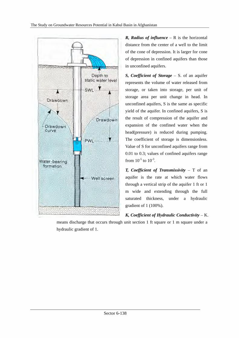
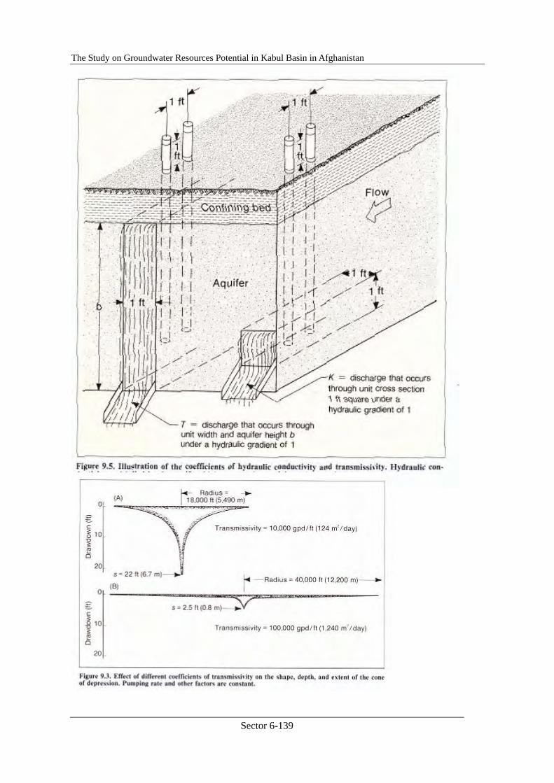
R, Radius of influence – R is the horizontal distance from the center of a well to the limit of the cone of depression. It is larger for cone of depression in confined aquifers than those in unconfined aquifers.
S, Coefficient of Storage – S. of an aquifer represents the volume of water released from storage, or taken into storage, per unit of storage area per unit change in head. In unconfined aquifers, S is the same as specific yield of the aquifer. In confined aquifers, S is the result of compression of the aquifer and expansion of the confined water when the head(pressure) is reduced during pumping. The coefficient of storage is dimensionless. Value of S for unconfined aquifers range from 0.01 to 0.3; values of confined aquifers range from 10-5 to 10-3.
T, Coefficient of Transmissivity – T of an aquifer is the rate at which water flows through a vertical strip of the aquifer 1 ft or 1 m wide and extending through the full saturated thickness, under a hydraulic gradient of 1 (100%).
K, Coefficient of Hydraulic Conductivity – K. means discharge that occurs through unit section 1 ft square or 1 m square under a hydraulic gradient of 1.
The Study on Groundwater Resources Potential in Kabul Basin in Afghanistan
Sector 6-139
The Study on Groundwater Resources Potential in Kabul Basin in Afghanistan
Sector 6-140
2. CONSTANT DISCHARGE TEST
2.1 Equilibrium Well Equation
More than a hundred years ago, engineers began work on adapting Darcy’s basic flow equation to groundwater flow toward a pumping well. The objective was to derive simple mathematical expressions for describing the flow regime of water in the ground.
Well discharge equations for equilibrium conditions were derived by various investigators. These equations relating well discharge to drawdown assumed two-dimensional radial flow toward a well. There are two basic equations; one for unconfined conditions and the other for confined conditions. Foe both equations, all dynamic conditions in the well and ground are assumed to be in equilibrium; that is, the discharge is constant, the drawdown and radius of influence have stabilized, and water enters the well in equal volumes from all directions. Both assume horizontal flow everywhere in the aquifer with recharge occurring at the periphery of the cone of depression.
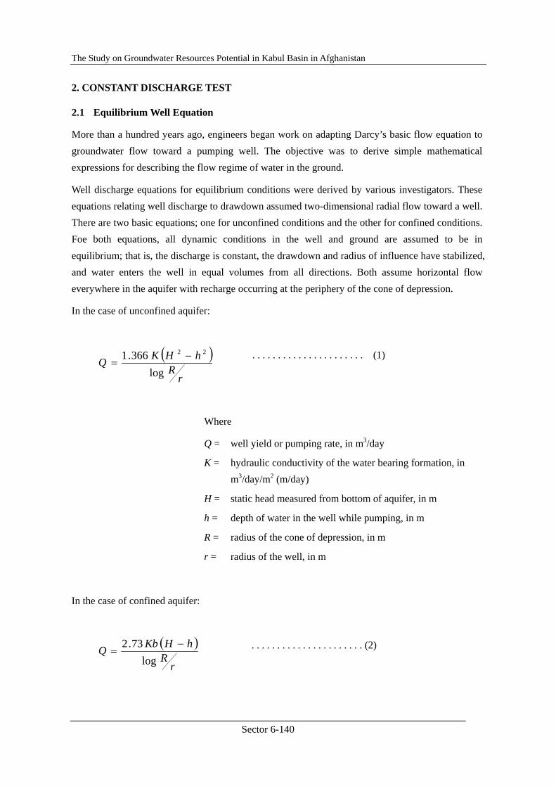
In the case of unconfined aquifer:
. . . . . . . . . . . . . . . . . . . . . . (1)
Where
Q = well yield or pumping rate, in m3/day
K = hydraulic conductivity of the water bearing formation, in m3/day/m2 (m/day)
H = static head measured from bottom of aquifer, in m
h = depth of water in the well while pumping, in m
R = radius of the cone of depression, in m
r = radius of the well, in m
In the case of confined aquifer:
. . . . . . . . . . . . . . . . . . . . . . (2)
( )r
RhHKQ
log366.1 22 −
=
( )
rR
hHKbQlog
73.2 −=

The Study on Groundwater Resources Potential in Kabul Basin in Afghanistan
Sector 6-141
Where
b = thickness of aquifer, in m]
All other terms are as defined above.
Equations (1) and (2) can be modified to calculate hydraulic conductivity. H and R are determined from a pumping test, and b is known from the drilling. In an unconfined aquifer, the equation for calculating K is:
. . . . . . . . . . . . . . . . . . . . . . . . (3)
Where
r1 = distance to the nearest well, in m
r2 = distance to the farthest well, in m
h2 = saturated thickness in the farthest observation well
h1 = saturated thickness in the nearest observation well
All others are same with above.
For confined aquifer, the equation for determining the hydraulic conductivity from a test
)(366.1
log2
12
2
1
2
hhr
rQK
−=
The Study on Groundwater Resources Potential in Kabul Basin in Afghanistan
Sector 6-142
installation similar to Figure 9.10 is:
. . . . . . . . . . . . . . . . . . . . . . . .(4)
Where
All terms except the followings are the same with above
b = thickness of the aquifer, in m
h2 = head, in m, at the farthest observation well, measured from the bottom of the aquifer
h1 = head, in m, at the nearest observation well, measured from the bottom of the aquifer.
All of the variables in the right side, Q, r2, r1, b, h2, h1, are known from the pumping test and well drilling, therefore, the hydraulic conductivity K in this aquifer can be calculated. If K is known, the coefficient of transmissivity T is also calculated as Kb.
However, deviations of these equations are based on the following simplifying assumptions:
1. The water-bearing materials have a uniform hydraulic conductivity within the radius of influence of the well.
2. The aquifer is not stratified. 3. For an unconfined aquifer, the saturated thickness is constant before pumping starts; for a
confined aquifer, the aquifer thickness is constant. 4. The pumping well is 100% efficient, that is, the drawdown levels inside and just outside
the well bore are at same elevation. 5. The intake portion of the well penetrates the entire aquifer. 6. The water table or potensiometric surface has no slope. 7. Laminar flow exists throughout the aquifer and within the radius of influence of the well. 8. The cone of depression has reached equilibrium so that both drawdown and radius of
influence of the well do not change with constant pumping at a given rate.
These assumptions appear to limit severely the use of these equations. In realty, however, they do not. For example, uniform hydraulic conductivity is rarely found in a real aquifer. But the average hydraulic conductivity as determined from pumping tests has proved to be reliable for predicting well performance. In confined aquifers where the well is fully penetrating and open to the formation, the assumption of no stratification is not as important limitation.
)(73.12
log
12
1
2
hhbr
rQK
−=
The Study on Groundwater Resources Potential in Kabul Basin in Afghanistan
Sector 6-143
2.2 Non-equilibrium Well Equation
Theis developed the nonequilibrium well equation in 1935. The Theis equation was the first to take into account the effect of pumping time on well yield. Its deviation was a major advance in groundwater hydraulics. By use of this equation, the drawdown can be predicted at any time after pumping begins. Transmissivity and average hydraulic conductivity can be determined during the early stages of a pumping test rather than after water levels in observation wells have virtually stabilized. Aquifer coefficients can be determined from the time-drawdown measurements in a single observation well rather than from two observation wells as requirement in Equation (3) and (4).
Deviation of Theis equation is based on the following assumptions:
1. The water-bearing formation is uniform in character and the hydraulic conductivity is same in all directions.
2. The formation is uniform in thickness and infinite in aerial extent. 3. The formation receives no recharge from any source. 4. The pumped well penetrates, and receives water from, the full thickness of the
water-bearing formation. 5. The water removed from storage is discharged instantaneously when the head is
lowered. 6. The pumping well is 100% efficient. 7. All water removed from the well comes from aquifer storage. 8. Laminar flow exists throughout the well and aquifer. 9. The water table or potentiometric surface has no slope.
These assumptions are essentially the same as those for the equilibrium equation except that the water levels within the corn of depression need not have stabilized or reached equilibrium.
Theis equation is, in its simplest form:
. . . . . . . . . . . . . . . . . . . . . . . . (5)
. . . . . . . . . . . . . . . . . . . . . . . . (6)
)(41 uW
TQs
π=
TtSru
4
2
=

The Study on Groundwater Resources Potential in Kabul Basin in Afghanistan
Sector 6-144
where
s = drawdown, in m, at any point in the vicinity of a well discharging at a constant rate
Q = pumping rate, in m3/day T = coefficient of Transmissivity of the aquifer, in m2/day W(u) = is read “well function of u” and represents as exponential
integral r = distance, in m, from the center of a pumped well to a
point where drawdown is measured S = coefficient of storage (dimensionless) t = time since pumping started.
Analysis of pumping test data using the Theis equation can yield Transmissivity and storage coefficients for all nonequilibrium situations. In actual practice, however, the Theis method is often avoided because it requires curve-matching interpretation and is somewhat laborious.
Use of the nonequilibrium
equation requires that data be plotted on log graph paper as shown in Figure 9.47. Drawdown; d1 is on the vertical axis and the time since pumping began is on the horizontal axis. This graph is
then superimposed on
the type-curve sheet (so-called as Theis’s Standard Curve) so the plotted points fall on or fit some portion of the type curve. In finding the position of best fit, the axes of both graphs must be kept parallel.
The Study on Groundwater Resources Potential in Kabul Basin in Afghanistan
Sector 6-145
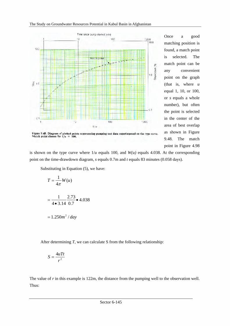
Once a good matching position is found, a match point is selected. The match point can be any convenient point on the graph (that is, where u equal 1, 10, or 100, or s equals a whole number), but often the point is selected in the center of the area of best overlap as shown in Figure 9.48. The match point in Figure 4.98
is shown on the type curve where 1/u equals 100, and W(u) equals 4.038. At the corresponding point on the time-drawdown diagram, s equals 0.7m and t equals 83 minutes (0.058 days).
Substituting in Equation (5), we have:
After determining T, we can calculate S from the following relationship:
The value of r in this example is 122m, the distance from the pumping well to the observation well. Thus:
daym
uWT
/250.1
038.47.073.2
14.341
)(41
2=
••
=
=π
2
4ruTtS =

The Study on Groundwater Resources Potential in Kabul Basin in Afghanistan
Sector 6-146
2.3 Modified Non-equilibrium Equation
In working with the Theis equation, Cooper and Jacob (1946) point out that when u is sufficiently small, the nonequilibrium equation can be modified to the following form without significant error:
. . . . . . . . . . . . . . . . . . . . (7)
where the symbols represent the same terms as shown above.
For values of u less than about 0.05, Equation (7) gives essentially the same results as Equation (6). The value of u becomes smaller as t increases and r decreases. Thus, Equation (7) is valid when t is sufficiently large and r is sufficiently small. Equation (7) is similar in form to the Theis equation except that the exponential integral function, W(u), has been replaced by a logarithmic term which is easier to work with in practical applications of well hydraulics.
For a particular situation where the pumping rate is held constant, Q, T, and S are all constants. Equation (7) shows, therefore, that the drawdown, s, varies with logt/r2 when u is less than 0.05. From this relationship, two important relationships can be stated:
1. For a particular aquifer at any specific point (where r is constant), the terms s and t are the only variable in Equation (7). Thus, s varies as logC1t, where C1 represents all the constant terms in the equation.
2. For a particular formation and at a given value of t, the terms s and r are the only variable in Equation (7). In this case, s varies as logC2/r2, where C2 represents all the constant terms in the equation, including the specific value of t.
By using these simplified relationships based on Equation (7), it is possible to derive information on the hydraulic
SrTt
TQs 2
25.2log183.0=
4
2
109.1)122(100
058.0250.114
−=
••••
=
x
S
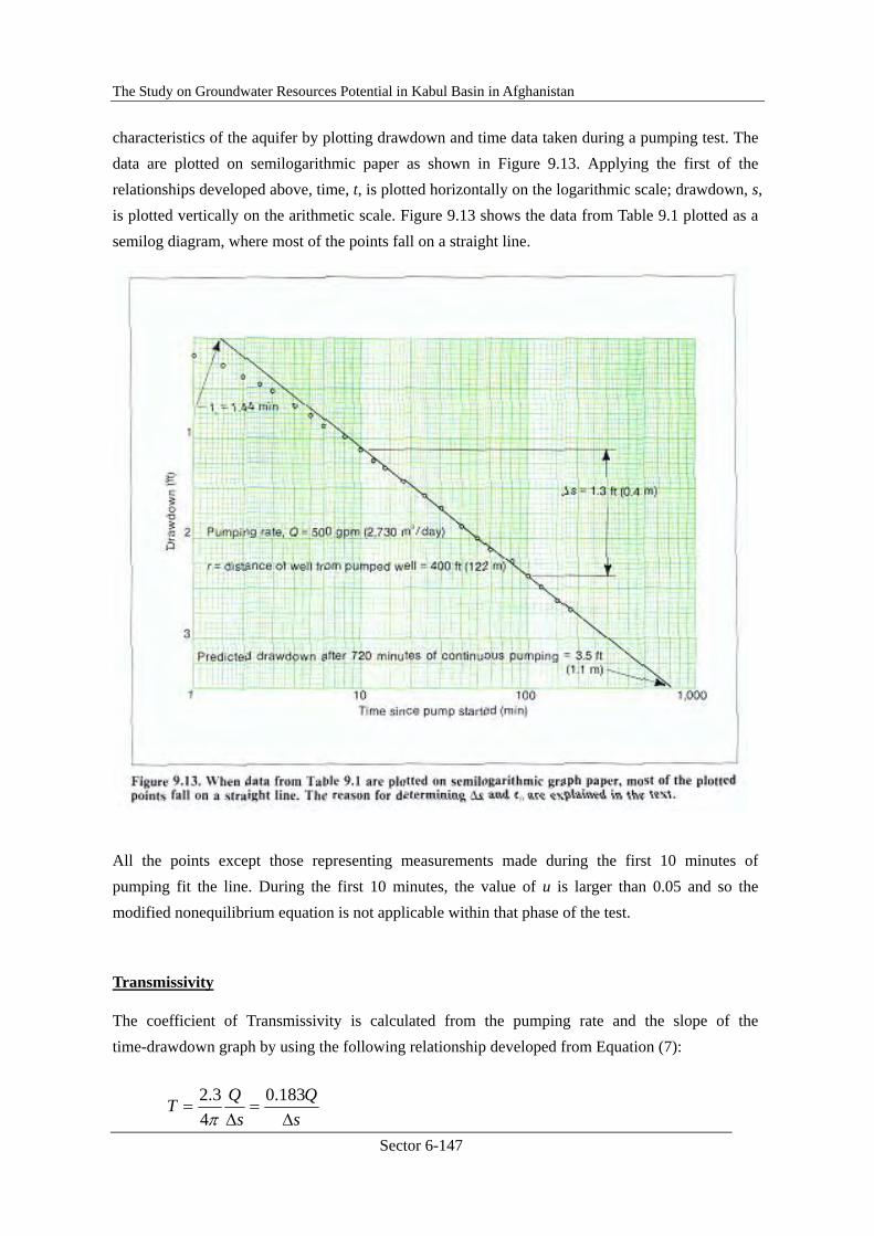
The Study on Groundwater Resources Potential in Kabul Basin in Afghanistan
Sector 6-147
characteristics of the aquifer by plotting drawdown and time data taken during a pumping test. The data are plotted on semilogarithmic paper as shown in Figure 9.13. Applying the first of the relationships developed above, time, t, is plotted horizontally on the logarithmic scale; drawdown, s, is plotted vertically on the arithmetic scale. Figure 9.13 shows the data from Table 9.1 plotted as a semilog diagram, where most of the points fall on a straight line.
All the points except those representing measurements made during the first 10 minutes of pumping fit the line. During the first 10 minutes, the value of u is larger than 0.05 and so the modified nonequilibrium equation is not applicable within that phase of the test.
Transmissivity
The coefficient of Transmissivity is calculated from the pumping rate and the slope of the time-drawdown graph by using the following relationship developed from Equation (7):
sQ
sQT
Δ=
Δ=
183.04
3.2π
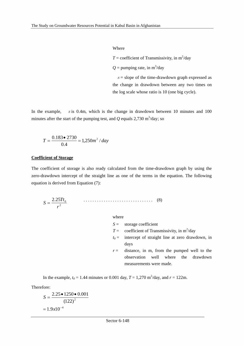
The Study on Groundwater Resources Potential in Kabul Basin in Afghanistan
Sector 6-148
Where
T = coefficient of Transmissivity, in m2/day
Q = pumping rate, in m3/day
�s= slope of the time-drawdown graph expressed as the change in drawdown between any two times on the log scale whose ratio is 10 (one big cycle).
In the example, �sis 0.4m, which is the change in drawdown between 10 minutes and 100 minutes after the start of the pumping test, and Q equals 2,730 m3/day; so
Coefficient of Storage
The coefficient of storage is also ready calculated from the time-drawdown graph by using the zero-drawdown intercept of the straight line as one of the terms in the equation. The following equation is derived from Equation (7):
. . . . . . . . . . . . . . . . . . . . . . . . . . . . . . . (8)
where S = storage coefficient T = coefficient of Transmissivity, in m2/day t0 = intercept of straight line at zero drawdown, in
days r = distance, in m, from the pumped well to the
observation well where the drawdown measurements were made.
In the example, t0 = 1.44 minutes or 0.001 day, T = 1,270 m2/day, and r = 122m.
Therefore:
daymT /250,14.02730183.0 2=
•=
2025.2
rTt
S =
4
2
109.1)122(
001.0125025.2
−=
••=
x
S
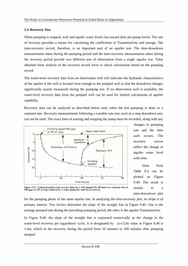
The Study on Groundwater Resources Potential in Kabul Basin in Afghanistan
Sector 6-149
2.4 Recovery Test
When pumping is stopped, well and aquifer water levels rise toward their pre-pump levels. The rate of recovery provides a means for calculating the coefficients of Transmissivity and storage. The time-recovery record, therefore, is an important part of an aquifer test. The time-drawdown measurements taken during the pumping period and the time-recovery measurements taken during the recovery period provide two different sets of information from a single aquifer test. Value obtained from analysis of the recovery record serve to check calculations based on the pumping record.
The water-level recovery data from an observation well will indicates the hydraulic characteristics of the aquifer if the well is located close enough to the pumped well so that the drawdown changes significantly (easily measured) during the pumping test. If no observation well is available, the water-level recovery data from the pumped well can be used for limited calculations of aquifer capability.
Recovery data can be analyzed as described below only when the test pumping is done as a constant rate. Recovery measurements following a variable-rate test, such as a step-drawdown test, can not be used. The exact time of starting and stopping the pump must be recorded, along with any
changes in pumping rate and the time each occurs. The recovery curves reflect the change in aquifer water level with time.
Data from Table 9.4 can be plotted as Figure 9.40. The result is similar to a time-drawdown plot
for the pumping phase of the same aquifer test. In analyzing the time-recovery plot, its slope is of primary interest. Two factors determine the slope of the straight line in Figure 9.40. One is the average pumped rate during the preceding pumping period, the other is the aquifer Transmissivity.
In Figure 9.40, the slope of the straight line is expressed numerically as the change in the water-level recovery per logarithmic cycle. It is designated by �(s-s’).Its value in Figure 9.40 is 1.6m, which in the recovery during the period from 10 minutes to 100 minutes after pumping stopped.
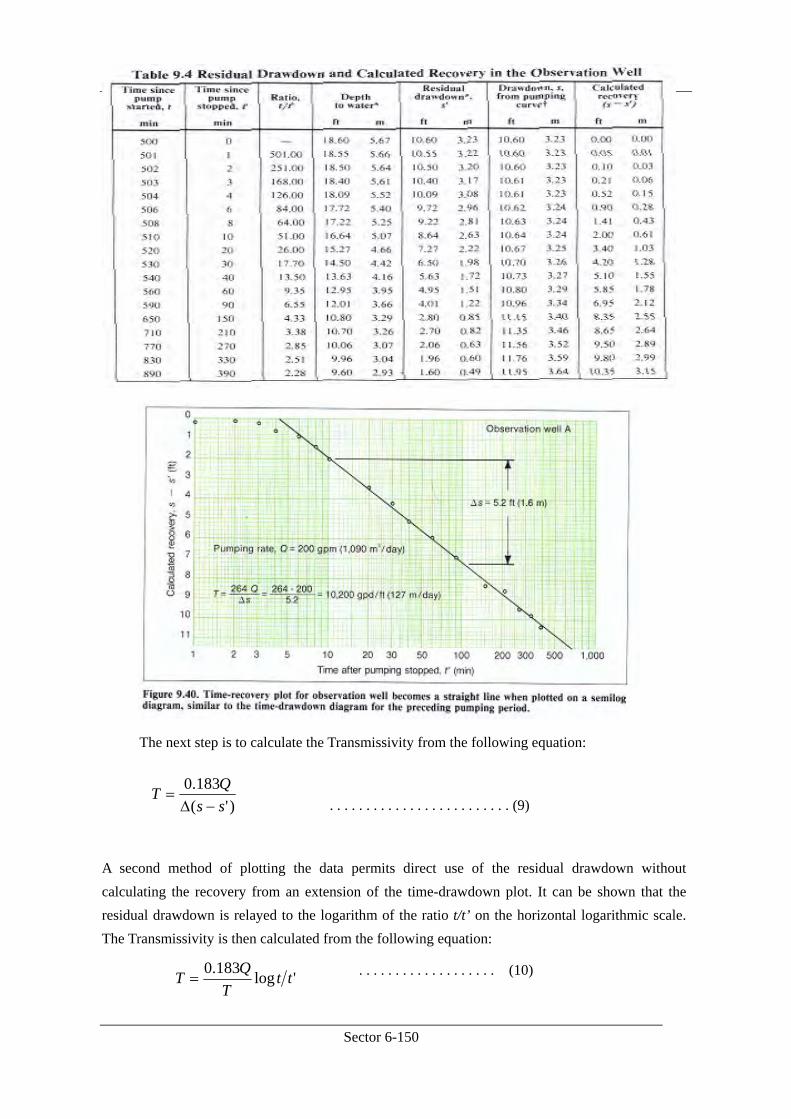
The Study on Groundwater Resources Potential in Kabul Basin in Afghanistan
Sector 6-150
The next step is to calculate the Transmissivity from the following equation:
. . . . . . . . . . . . . . . . . . . . . . . . . (9)
A second method of plotting the data permits direct use of the residual drawdown without calculating the recovery from an extension of the time-drawdown plot. It can be shown that the residual drawdown is relayed to the logarithm of the ratio t/t’ on the horizontal logarithmic scale. The Transmissivity is then calculated from the following equation:
. . . . . . . . . . . . . . . . . . . (10)
)'(183.0
ssQT
−Δ=
'log183.0 ttT
QT =
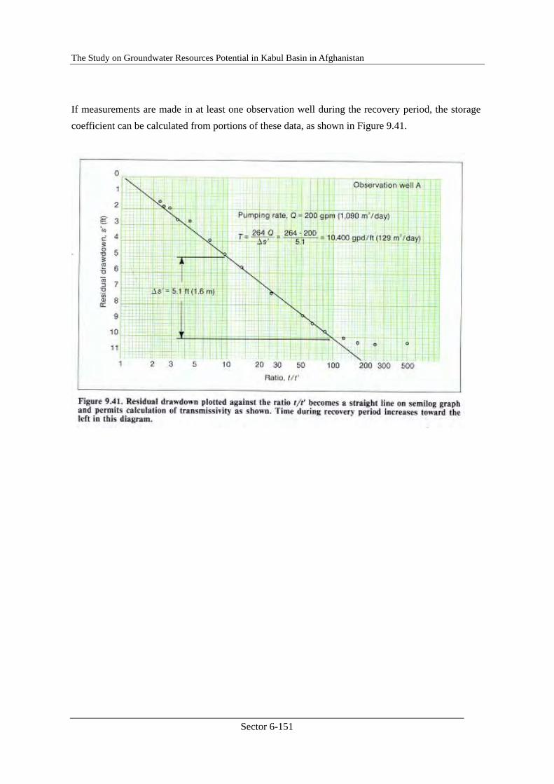
The Study on Groundwater Resources Potential in Kabul Basin in Afghanistan
Sector 6-151
If measurements are made in at least one observation well during the recovery period, the storage coefficient can be calculated from portions of these data, as shown in Figure 9.41.
The Study on Groundwater Resources Potential in Kabul Basin in Afghanistan
Sector 6-152
3. STEP DRAW-DOWN TEST
The step drawdown test has been developed to examine the performance of wells having turbulent flow (Jacob, 1946). In a step-drawdown test, the well is pumped at several successive higher pumping rates and the drawdown for each rate, or step, is recorded. The entire test is usually conducted during one day, and calculations are simplified if all the pumping times are the same for each discharge rate. If time permits, the water level should be allowed to recover to the static level between each step. Usually five to eight pumping steps are used, each lasting 1 to 3 hours. The data from a step test can be used to determine the relative proportion of laminar and turbulent flow occurring at any pumping rate.
Recall from the previous section, foe laminar flow condition in a perfect well, drawdown in a confined aquifer can be expressed as follows:
. . . . . . . . . . . . . . . . . (11)
This equation is also applicable to unconfined aquifer as long as the drawdown is small in relation to aquifer thickness.
Equation (11) can be shortened to:
s = BQ . . . . . . . . . . . . . . . . . . . . . . . . . . . . . . . . (12)
where
For a specific well, the value of B is time dependant. However, B changes only slightly after a reasonable pumping duration and can thus be assumed to be a constant. When turbulent flow exists, Jacob suggests that the drawdown in a well can be more accurately expressed as the sum of a first-order (laminar) component and a second-order (turbulent) component:
. . . . . . . . . . . . . . . . . . . . . . . . . (13)
In this equation, Jacob called the laminar term (BQ) the “aquifer loss” and the turbulent term (CQ2)
SrTt
TQs 2
25.2log183.0=
SrTt
TQB 2
25.2log183.0=
2CQBQs +=
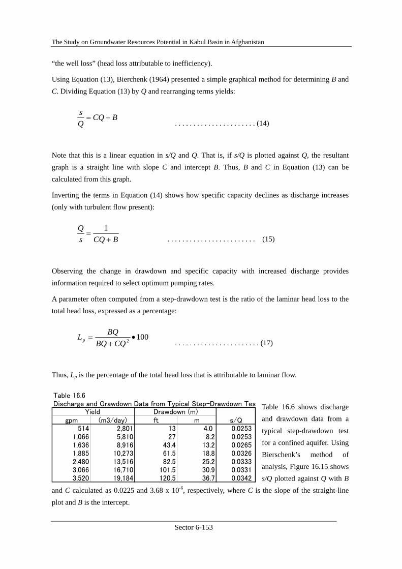
The Study on Groundwater Resources Potential in Kabul Basin in Afghanistan
Sector 6-153
“the well loss” (head loss attributable to inefficiency).
Using Equation (13), Bierchenk (1964) presented a simple graphical method for determining B and C. Dividing Equation (13) by Q and rearranging terms yields:
. . . . . . . . . . . . . . . . . . . . . . (14)
Note that this is a linear equation in s/Q and Q. That is, if s/Q is plotted against Q, the resultant graph is a straight line with slope C and intercept B. Thus, B and C in Equation (13) can be calculated from this graph.
Inverting the terms in Equation (14) shows how specific capacity declines as discharge increases (only with turbulent flow present):
. . . . . . . . . . . . . . . . . . . . . . . . (15)
Observing the change in drawdown and specific capacity with increased discharge provides information required to select optimum pumping rates.
A parameter often computed from a step-drawdown test is the ratio of the laminar head loss to the total head loss, expressed as a percentage:
. . . . . . . . . . . . . . . . . . . . . . . (17)
Thus, Lp is the percentage of the total head loss that is attributable to laminar flow.
Table 16.6 shows discharge and drawdown data from a typical step-drawdown test for a confined aquifer. Using Bierschenk’s method of analysis, Figure 16.15 shows s/Q plotted against Q with B
and C calculated as 0.0225 and 3.68 x 10⁻⁶, respectively, where C is the slope of the straight-line plot and B is the intercept.
BCQQs
+=
BCQsQ
+=
1
1002 •+=
CQBQBQLp
Table 16.6 Discharge and Grawdown Data from Typical Step-Drawdown Tes
gpm (m3/day) ft m s/Q514 2,801 13 4.0 0.0253
1,066 5,810 27 8.2 0.02531,636 8,916 43.4 13.2 0.02651,885 10,273 61.5 18.8 0.03262,480 13,516 82.5 25.2 0.03333,066 16,710 101.5 30.9 0.03313,520 19,184 120.5 36.7 0.0342
Yield Drawdown (m)
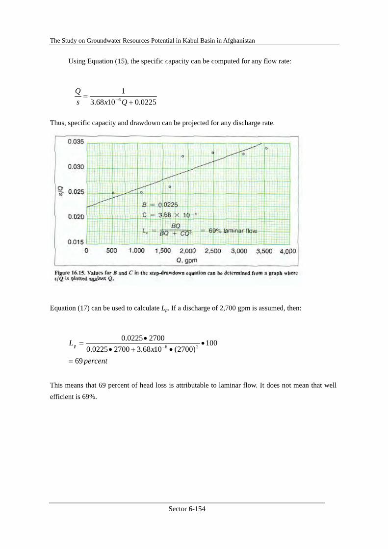
The Study on Groundwater Resources Potential in Kabul Basin in Afghanistan
Sector 6-154
Using Equation (15), the specific capacity can be computed for any flow rate:
Thus, specific capacity and drawdown can be projected for any discharge rate.
Equation (17) can be used to calculate Lp. If a discharge of 2,700 gpm is assumed, then:
This means that 69 percent of head loss is attributable to laminar flow. It does not mean that well efficient is 69%.
0225.01068.31
6 += − Qxs
Q
percentx
Lp
69
100)2700(1068.327000225.0
27000225.026
=
••+•
•= −
The Study on Groundwater Resources Potential in Kabul Basin in Afghanistan
Sector 6-155
2.6. Cost Estimation and Tendering
2.6.1. Cost Estimation and Tendering, Main Text
JICA Training Lecture Text ⑥ Aspect : COST ESTIMATION & TENDERING
Contents
Chapter 1. Cost Estimation ....................................................................................... 6-156 1.1. Cost Estimation General............................................................................... 6-156 1.2. Contents of Project Cost............................................................................... 6-157 1.3. Direct Construction Cost .............................................................................. 6-158 1.4. Common Temporary Work........................................................................... 6-159 1.5. Site Administration Cost .............................................................................. 6-161 1.6. Administration Cost ..................................................................................... 6-162 1.7. Cost Estimation on Drilling Work................................................................ 6-163
Chapter 2. Tendering and Contract............................................................................ 6-164
2.1. Tendering ......................................................................................................... 6-164 2.1.1. Tender general ......................................................................................... 6-164 2.1.2. Tendering Procedures .............................................................................. 6-164 2.1.3. Prequalification........................................................................................ 6-164 2.1.4. Public Notice ........................................................................................... 6-165 2.1.5. Tender documents.................................................................................... 6-166 2.1.6. Tendering................................................................................................. 6-168
2.2. Contract ........................................................................................................... 6-170 2.2.1. Contract general....................................................................................... 6-170 2.2.2. Contract form........................................................................................... 6-171
References
Attachment-1. Sample of Cost Estimation (Pumping Test) Attachment-2. Sample lf PQ Notice Attachment-3. Sample of PQ Documents Attachment-4. Sample of Tender Notice Attachment-5. Sample of Tender Documents Attachment-6. Sample of Contract Form
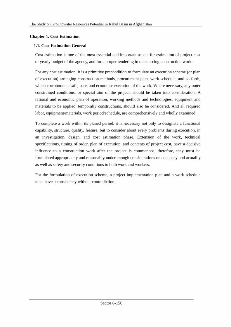
The Study on Groundwater Resources Potential in Kabul Basin in Afghanistan
Sector 6-156
Chapter 1. Cost Estimation
1.1. Cost Estimation General
Cost estimation is one of the most essential and important aspect for estimation of project cost or yearly budget of the agency, and for a proper tendering in outsourcing construction work.
For any cost estimation, it is a primitive precondition to formulate an execution scheme (or plan of execution) arranging construction methods, procurement plan, work schedule, and so forth, which corroborate a safe, sure, and economic execution of the work. Where necessary, any outer constrained conditions, or special aim of the project, should be taken into consideration. A rational and economic plan of operation, working methods and technologies, equipment and materials to be applied, temporally constructions, should also be considered. And all required labor, equipment/materials, work period/schedule, are comprehensively and wholly examined.
To complete a work within its planed period, it is necessary not only to designate a functional capability, structure, quality, feature, but to consider about every problems during execution, in an investigation, design, and cost estimation phase. Extension of the work, technical specifications, timing of order, plan of execution, and contents of project cost, have a decisive influence to a construction work after the project is commenced, therefore, they must be formulated appropriately and reasonably under enough considerations on adequacy and actuality, as well as safety and security conditions to both work and workers.
For the formulation of execution scheme, a project implementation plan and a work schedule must have a consistency without contradiction.
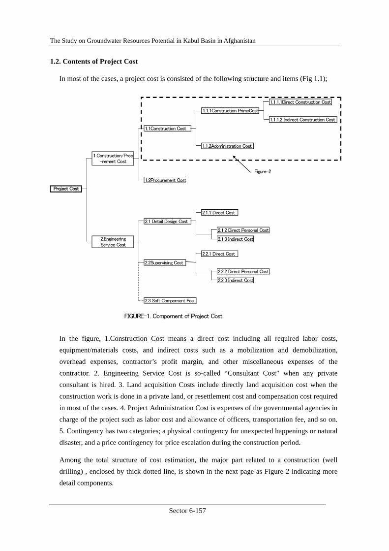
The Study on Groundwater Resources Potential in Kabul Basin in Afghanistan
Sector 6-157
1.2. Contents of Project Cost
In most of the cases, a project cost is consisted of the following structure and items (Fig 1.1);
In the figure, 1.Construction Cost means a direct cost including all required labor costs, equipment/materials costs, and indirect costs such as a mobilization and demobilization, overhead expenses, contractor’s profit margin, and other miscellaneous expenses of the contractor. 2. Engineering Service Cost is so-called “Consultant Cost” when any private consultant is hired. 3. Land acquisition Costs include directly land acquisition cost when the construction work is done in a private land, or resettlement cost and compensation cost required in most of the cases. 4. Project Administration Cost is expenses of the governmental agencies in charge of the project such as labor cost and allowance of officers, transportation fee, and so on. 5. Contingency has two categories; a physical contingency for unexpected happenings or natural disaster, and a price contingency for price escalation during the construction period.
Among the total structure of cost estimation, the major part related to a construction (well drilling) , enclosed by thick dotted line, is shown in the next page as Figure-2 indicating more detail components.
1.1.1.1Direct Construction Cost
1.1.1.2 Indirect Construction Cost
1.1Construction Cost
1.1.2Adoministration Cost
Figure-2
1.2Procurement Cost
2.1.1 Direct Cost
2.1 Detail Design Cost
2.1.2 Direct Personal Cost
2.1.3 Indirect Cost
2.2.1 Direct Cost
2.2Supervising Cost
2.2.2 Direct Personal Cost
2.2.3 Indirect Cost
2.3 Soft Compornent Fee
FIGURE-1. Compornent of Project Cost
1.Construction/Proc-rement Cost
2.EngineeringService Cost
1.1.1Construction PrimeCost
Project Cost

The Study on Groundwater Resources Potential in Kabul Basin in Afghanistan
Sector 6-158
Each cost estimation item included in “1.1.1.1Direct Construction Cost”, “Common Temporary Work” and “Site Administration Cost”, both under “1.1.1.2 Indirect Construction Cost”, and “1.1.2. Administration Cost” are roughly explained in the following sections.
1.3. Direct Construction Cost
Direct construction cost means expenses for labor, equipment/materials, machineries, and others which directly required constructing objective well(s) or constructions(s). Items accounted as a direct construction cost are listed bellow.
a. Labor Cost: (1) Cost of labors working to construct or removal of target building, construction, or wells.
(2) Cost of labors working for a temporary work.
(3) Cost of labors operating machine, equipment or tools.
Labor Cost
Expert Fee
Material Cost
Direct Expenses
1.1.1.1Direct Construction Cost Temporary Work
Transportation Fee
Others
Package/Transport
Common Temporary Work Preaparatory Work
1.1Construction Cost 1.1.1.2 Indirect Construction Cost Guard system fee
Security system fee
Service Fee
Technical Control Fee
Building/Repairment Fee
Others
1.1.2Adoministration Cost Labor Control Fee
Safety Measurement
Site Administration Cost Insurerance
Staff salary/perdiem
Travel Allowance
Retirement Allowance
Legar Welfare Expenses
Welfare Expenses
Office Supplies
Communication/Transport
Compensation Cost
Sub-contract Cost
Inspection Fee
Miscereneous Expemses
FIGURE-2. Compornent of Construction Cost
1.1.1Construction Prime Cost
The Study on Groundwater Resources Potential in Kabul Basin in Afghanistan
Sector 6-159
(4) Cost of labors concerning for transportation.
b. Expert Fee: (1) Expenses for experts or specialists dispatched to the site.
c. Material Cost: (1) Direct material cost-Cost of materials directly required to construct the structure or well, and handling fee.
(2) Consumption Fee-Expenses for fuel, oil, and other consumptions
d. Direct Expenses: (1) Cost for patents – Expenses for using patent or technique using under contract.
(2) Heat, light and water cost – fees for power, water, gas actually used.
(3) Rental Fee – Equipment, machinery hire fee, operation cost, rental fee.
e. Temporary work: Costs for temporary work such as temporary structures, plants, power facility, fences or wall, water supply, power supply, etc.
f. Packing/Transportation: Expenses for packing and transportation of equipment/materials from the procured place to target site.
g. Others: (1) Expenses for setting plate, sticker, logo-marks, etc.
(2) Other expenses not included above items.
1.4. Common Temporary Work
Common temporary work means expenses required not for construction of target structures (or wells) directly but for commonly required expenses by every work. Items to be accounted in this category are as listed bellow.
a. Transport/Packing Fee: (1) Cost for moving of self-running equipment.
(2) Cost for removing equipment, materials, machines, etc., inside the compound.
(3) Cost for packing/transportation of equipment/materials procured locally from the procured place to the construction site.
(4) Costs for mounting/demounting of above equipment.
b. Preparatory Work: (1) Expenses for preparation, survey, investigation, site clearing.
(2) Expenses for tree trimming, root exemption, land
The Study on Groundwater Resources Potential in Kabul Basin in Afghanistan
Sector 6-160
preparation, flattening, etc.
(3) Expenses for removing and treatment of solid waste from the site to outside.
c. Guard System Fee: Costs for guarding any losses may happen through noise, land subsidence, water shortage, etc., accompanied by the work.
d. Security System Cost: (1) Costs for setting, removing, and repairing of guide boards, plates, security lights, barricades, fences, etc.
(2) Costs for special security goods.
(3) Costs for traffic control and/or guide persons.
(4) Costs for any security systems required for safety construction work.
e. Service Fee: (1) Cost for acquisition or rental of the land.
(2) Basic costs of power supply and water supply, costs for supply systems.
f. Technical Control Fee: (1) Costs for investment required to keep good quality.
(2) Costs for survey, drawing, photo, etc., required to work quality control.
(3) Costs for data, document preparation required for work progress control.
(4) Costs for OA equipment required for supervising.
(5) Costs for special quality control.
(6) Special costs for supervising depending upon the site.
(7) Other costs required especially depending upon the site characteristics.
g. Building/Repairing Fee: (1) Costs for building, maintenance, and removal of consultant office and a site office.
(2) Costs for construction, maintenance, and removal of lodging houses of foreign and local workers.
(3) Costs for construction, maintenance, and removal of site laboratory, storehouse, workshop, and so on.
(4) Costs for furniture, equipment, fixtures, facilities, etc., of consultant and site offices.
The Study on Groundwater Resources Potential in Kabul Basin in Afghanistan
Sector 6-161
(5) Costs for furniture, equipment, fixtures, facilities, etc., of lodging house.
(6) Costs for acquisition or rental fee on the land required in “building/repairing”.
(7) Costs for setting, maintenance, and charge on power/water supply systems, heat and gas supply system of site office, lodging house and so on.
(8) Costs required for transporting workers.
h. Others: (1) Costs for providing, setting, and removal on site guide board.
(2) Costs not included in upper items.
1.5. Site Administration Cost
Site administration cost means expenses required to progress the work smooth and just on-time, and the costs required to control and administrate every event and accidents happened on the course of work progress.
Items to be accounted in the site administration cost are as listed bellow.
a. Labor Control Fee: (1) Recruitment/dismissal Costs: Expenses for recruiting and dismissal of site workers.
(2) Welfare Costs: Expenses for recreation/amusement and welfare for site workers.
(3) Clothing Allowance: Expenses for working cloth and goods not included in construction cost for site workers.
(4) Food and Commutation Costs: Expenses on food and commutation not included in salary.
(5) Charge for accident allowance: Charge of client when any accident happened.
b. Safety and Health Cost: Expenses required for keeping safety and health of site workers, and for training of the workers.
c. Insurance: (1) Work Insurance: Work insurance.
(2) Other Insurance: Expenses for other damage insurance such as fire insurance.
The Study on Groundwater Resources Potential in Kabul Basin in Afghanistan
Sector 6-162
(3) Car Insurance: Insurance for cars.
d. Salary and Allowance: Salaries for all workers including bonus and allowances.
e. Travel fee/Per diem: Travel fee, per diem and lodging allowance of all workers.
f. Retire Allowance: Allowance for retirement in accordance with the related law of the country.
g. Legal Welfare: Expenses for legal welfare of the workers in accordance with the related law of the country.
h. Welfare Cost: Expenses for rental cloth, recreation/amusement, medical care, occasional greeting, cultural activities, and so on for workers.
i. Office Supply: Expenses for office supply, OA equipment, Newspaper, reference bocks.
j. Communication/Transportation: (1) Communication Fee: Expenses for inter-net, telephone, facsimile, and mails.
(2) Transportation Fee: Expenses for purchase or rent, maintenance, and operation of cars for work control, and cost for commutation of workers.
k. Compensation Cost: Expenses for compensations on damages or excuse for noise, vibration, traffic jam, etc., caused by the work
l. Sub-contract Cost: Cost for sub-contract to local or special company/shop.
m. Inspection Cost: Expenses for travel, per diem, lodging fee required to inspect the work of sub-contractor.
n. Miscellaneous Cost: (1) Transportation Fee: Expenses for welcomes of guests.
(2) Other Miscellaneous Costs: Other expenses not included in above a. to m.
1.6. Administration Cost
The administration cost means expenses to keep, operate and administrate the company in proper condition. The cost is consisted of (1) Common administration cost and (2) Profit of the company.
Items to be accounted in the administration cost are listed bellow.
(1) Common Administration Cost a. Director’s Remuneration: Remuneration for directors.
The Study on Groundwater Resources Potential in Kabul Basin in Afghanistan
Sector 6-163
b. Salary and Allowance: Salary and allowance of employmees.
c. Retire Allowance: Allowance for retirement of employees.
d. Legal Welfare Cost: Legal welfare costs for employees.
e. Welfare Cost: Expenses for rental cloth, recreation/amusement, medical care, occasional greeting, cultural activities, and so on for workers.
f. Maintenance Cost: Costs for maintenance of building, machines, equipment, and materials in stockyard.
g. Office Supply Cost: Costs for office supply, providing newspaper, reference bock, and etc which are not including company asset.
h. Communication/Transportation: Costs for communication, transportation, and travel.
i. Power, Heat, & Water Supply: Costs for power, heat, and water supplies.
j. Research Expenditure: Costs for investigation, research, and technical development.
k. Advertising Cost: Costs for advertising activities.
l. Donation: Cost for any donation.
m. Rent Account: Costs for rental fee on land, office, dormitory, stockyard.
n. Depreciation Cost: Depreciation costs for building, vehicles, equipment, etc.
o. Others: Depreciation costs for technical development, new products, taxes, insurance, and miscellaneous expenses.
(2) Profit
a. Profit: Profits including taxes, dividend to stockholder, director’s bonus, inner suspension, interest payment, etc.
1.7. Cost Estimation on Drilling Work
In Attachment, a sample of cost estimation for Pumping Test including Well Drilling Work, or in exact saying; a base form of cost estimation on pumping test, is attached.
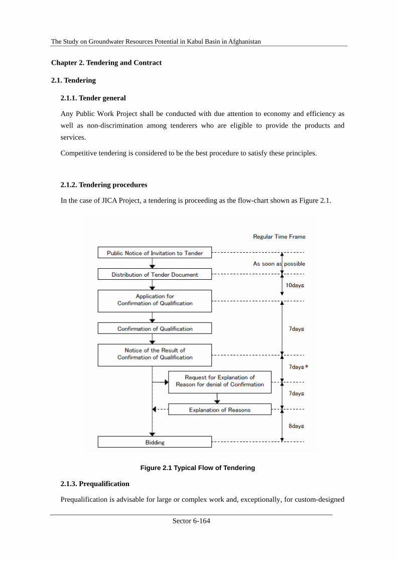
The Study on Groundwater Resources Potential in Kabul Basin in Afghanistan
Sector 6-164
Chapter 2. Tendering and Contract
2.1. Tendering
2.1.1. Tender general
Any Public Work Project shall be conducted with due attention to economy and efficiency as well as non-discrimination among tenderers who are eligible to provide the products and services.
Competitive tendering is considered to be the best procedure to satisfy these principles.
2.1.2. Tendering procedures
In the case of JICA Project, a tendering is proceeding as the flow-chart shown as Figure 2.1.
Figure 2.1 Typical Flow of Tendering
2.1.3. Prequalification
Prequalification is advisable for large or complex work and, exceptionally, for custom-designed
The Study on Groundwater Resources Potential in Kabul Basin in Afghanistan
Sector 6-165
equipment or specialized services to insure, in advance of tendering, that the invitation to tender is to be extended only to those who are capable. Prequalification should be based entirely on the capability and resources of potential tenderers to perform the particular work satisfactorily, taking into account, in particular:
1) their experience and past performance under similar contracts;
2) their experience and past performance in the recipient country and its neighboring countries;
3) their capabilities with respect to personnel, equipment and plant; and
4) their financial position.
The invitation to prequalification for a specific contract shall be publicly announced and notified as described in the following section. A clear statement of the scope of the contract and the requirements for qualification shall be sent to all those who wish to be considered for prequalification. As soon as prequalification is completed, the tender documents shall be issued to the qualified tenderers. All such tenderers that meet the specified criteria shall be allowed to tender.
The tender invitation should be prepared in Dari and English.
2.1.4. Public Notice
Public announcement shall be carried out in such a way that all potential tenderers will have fair opportunity to learn about and participate in the tender. Invitation to prequalification or to tender should be advertised in at least one newspaper in general circulation, and if any, in the official gazette in the recipient country or a general circulation newspaper in its neighboring countries or Japan. Items to be included in the public announcement are:
1) Name of the Project;
2) Brief description of the Project;
3) Name of the executing agency of the Project;
4) Qualification required of tenderer;
5) Date, time and place of the delivery of tender documents (date, time and place of the delivery of prequalification documents, in case of prequalification); and
6) Other relevant and important information that potential tenderers may need to determine whether to submit a tender.
The tender invitation, tender documents, and contracts should be prepared in Dari and English.
The Study on Groundwater Resources Potential in Kabul Basin in Afghanistan
Sector 6-166
A sample of tender invitation in English is presented in Attachment.
2.1.5. Tender documents
(1) General
Tender documents should provide all information necessary to enable tenderers to prepare valid offers for the products and services to be procured. Tender documents should be prepared by the Agency in charge of prior to public announcement. They should generally include:
1) Instruction to tenderers,
2) Form of tender,
3) Form of contract,
4) Technical specification, and
5) Necessary appendices, etc.
If a fee is charged for the tender documents, it should be reasonable and reflect the cost of their production, and should not be so high as to discourage potential tenderers.
(2) Clarity of Tender Documents
Tender documents should be so worded as to permit and encourage competitive tendering. They should describe as clearly as possible the products and services to be procured, qualification required of the tenderer, eligible sources countries, size of contract, the place and timing of delivery and/or installation, insurance, transportation, bond and warranty as well as other pertinent terms.
In addition, the tender documents, where appropriate, should define the tests, standards, and methods to be employed to judge conformity of the products and services to be procured with the required specification.
Drawings should be consistent with the text of the technical specifications.
Any additional information, clarification, correction of errors or alteration of tender documents should be promptly sent to all those who have requested the original tender documents in ample time before the date of tender submission so that tenderers can take appropriate action.
(3) Pricing and Currency of Tenders
Tender documents should clearly mention the following:
1) The tender price shall be stated in “Afghani” on the basis of a lump sum price, in conformity with the specification stipulated in the tender documents, and

The Study on Groundwater Resources Potential in Kabul Basin in Afghanistan
Sector 6-167
2) The tender price must be firm and final.
(4) Tender Bond or Guarantee
The amount of tender bond or other tender guarantees, if required, should not be set so high as to discourage potential tenderers. The tender bond or other guarantees should be released to unsuccessful tenderers as soon as possible after the award of contract.
(5) Method of Tender Evaluation
Tender documents should clearly state the method of tender evaluation. The statement should include the following:
The tenderer who, in compliance with the conditions and specifications stipulated in the tender documents, offers the lowest price shall be designated as the successful tenderer. In case the tender is divided into several packages, the statement should include the 12 following; “The tender evaluation shall be done separately.”
(6) Conditions of Contract
The tender documents should clearly define the conditions of contract such as the rights and obligations of the Recipient and the Contractor.
(6-1) Terms of Payment
The conditions of contract should state the terms of payment. In general, the terms of payment should be as follows:
1) In the case of contract for supply of products other than those mentioned in 2) below, the payment for the products will be made upon the completion of the shipment of the contracted products.
2) In the case of a contract for complex work for construction, or shipbuilding, or custom-designed equipment, a reasonable advance payment and/or regular progress payments may be applicable.
(6-2) Warranties
The conditions of contract should clearly state the time of commencement and the period of any warranties if those warranties are required.
(6-3) Performance Bond or Guarantee
The Contractor may be required to post a performance bond or guarantee. Such a bond or guarantee should be of a reasonable amount and should be released as soon as possible after the completion of the shipment of the contracted goods or of the services required under the contract.
The Study on Groundwater Resources Potential in Kabul Basin in Afghanistan
Sector 6-168
(6-4) Force Majeure
The conditions of contract should contain a clause stating that failure on the part of the Contractor to fulfill obligations under the contract would not be considered a default if such failure is the result of an event of force majeure. The scope of force majeure should be defined in the conditions of contract.
(6-5) Settlement of Disputes
Provisions dealing with the settlement of disputes should be included in the conditions of contract. It is advisable that the provisions be based on the "Rules of Arbitration" prepared by the International Chamber of Commerce.
(7) Specifications
Specifications, in particular technical specifications in the case of construction work, are one of the most important documents in the tendering process as they make enable tenderers to estimate the construction cost exactly. In Attachment, a sample of technical specifications on Drilling Work is presented.
2.1.6. Tendering
(1) Time Interval between Invitation and Submission of Tenders
The time allowed for preparation and submission of the tenders should be determined with due consideration of the particular circumstances of the project, and the size and complexity of the contract. Generally, the deadline for the submission of tenders should be set at least thirty days after the date when tender documents are made available for potential tenderers (See Figure 2.1).
(2) Procedures for Opening of Tenders
The date, time and place of the latest receipt as well as those of the tender opening should be announced at the time of invitation. All tenders should be opened in the presence of tenderers or their representatives at the fixed time and place. Tenders received after the announced deadline should not be considered and should be returned unopened. The names of the tenderers and total amount of each tender should be read aloud and recorded.
(3) Clarification or Alteration of Tenders
No tenderer should be permitted to alter its tender after the tenders have been opened. Clarifications without changing the substance of the tender may be accepted. The Recipient may ask any tenderer for clarification on its tender submitted, but should not ask any tenderer to change the substance or price of the tender.
The Study on Groundwater Resources Potential in Kabul Basin in Afghanistan
Sector 6-169
(4) Process to be Confidential
After the public opening of the tenders, information relating to the examination, clarification and evaluation of tenders and recommendations concerning award should not be disclosed to tenderers or other persons not officially concerned with the process, until the award of contract is announced.
(5) Examination of Tenders
Following the opening of tenders, it should be ascertained that i) computations are free of material errors, ii) the tenders are substantially responsive to the tender documents, iii) the required certificates have been provided, iv) the required securities have been provided, v) documents have been properly signed, and vi) the tenders are consistent with the instructions of the tender documents. If a tender does not substantially conform to the specifications, or contains inadmissible reservations or is otherwise not substantially responsive to the tender documents, it should be rejected. A technical analysis should then be made to evaluate each responsive tender and to enable tenders to be compared.
(6) Evaluation of Tenders
Tender evaluation shall be consistent with the terms and conditions stated in the tender documents. Those tenders which substantially conform to the technical specifications, and are responsive to other stipulations of the tender documents, shall be judged solely on the basis of the submitted price, and the tender who offers the lowest price shall be designated as the successful tenderer.
(7) Evaluation Report
A detailed evaluation report of tenders, giving the reasons for the acceptance or rejection of tenders, shall be prepared by the Recipient. The evaluation report will be submitted to JICA prior to the award of contract.
(8) Rejection of Tenders
Any tenders should not be rejected nor a new tender be invited using the same specifications solely for the purpose of obtaining lower prices in the new tender, except in the case where the lowest tender exceeds the cost estimates. Rejection of any tenders may only be justified when tenders do not comply with the tender documents. If all tenders are rejected, the Recipient should review the causes of the rejection, and consider revision of the specifications called for in the original invitation to tender.
(9) Award of Contract
The contract shall be awarded within the period specified for the validity of the tender, to the tenderer who, in compliance with the conditions and specifications stipulated in the tender
The Study on Groundwater Resources Potential in Kabul Basin in Afghanistan
Sector 6-170
documents, offers the lowest price.
No tenderer shall be required, as a condition of the award, to bear responsibilities or undertake services not stipulated in the tender documents.
2.2. Contract
2.2.1. Contract general
(1) General
The awarded contractor shall enter into contract(s) with the Agency in charge of. The contract(s) thus concluded shall become effective only after verification by the Government of Afghanistan (MOM).
(2) Scope of Work
The contract shall clearly state all products and services to be procured under the Project.
(3) Period of Execution
The contract shall clearly stipulate the period of execution of work; that the period shall not exceed the term of validity of the Project.
(4) Contract Price
The total amount of the contract price shall not exceed the amount of the Cost estimated by the Agency. The contract price shall be precisely and correctly stated in “Afghani” in the contract using both words and figures. If there is a difference between the price in words and that in figures, the price in words is deemed correct.
(5) Verification of Contract
The contract shall clearly state that it shall become effective only upon its verification by the Government of Afghanistan.
(6) Payment Method
Payment mode and method is clearly defined in the Contract Document.
(7) Responsibilities and Obligations of the Contractor
The contract shall clearly state the responsibilities and obligations of the Contractor.
(8) Amendment
If the contract requires amendment, it shall be done in the form of a contract of amendment, referring to the contract presently in force identified by its verification date and number. The

The Study on Groundwater Resources Potential in Kabul Basin in Afghanistan
Sector 6-171
contract of amendment shall clearly state that;
1) all the clauses except that which is or are amended, remain unchanged.
2) the contract of amendment shall become effective only after its verification by the Government of Afghanistan.
2.2.2. Contract form
Samples of Contract are presented in Attachment.
The Study on Groundwater Resources Potential in Kabul Basin in Afghanistan
Sector 6-172
2.7. Supervising and Project Evaluation
2.7.1. Supervising and Project Evaluation, Main Text
JICA Training, Lecture Text ⑦
Aspect : SUPERVISING & EVALUATION
Contents
Chapter 1. Supervising .............................................................................................. 6-173
1.1. Supervising General ..................................................................................... 6-173
1.2. Work Records ............................................................................................... 6-175
1.3. Completion Report ....................................................................................... 6-176
1.4. Supervising for Well Construction Work ..................................................... 6-176
Chapter 2. Project Evaluation ................................................................................... 6-180
2.1. Concept of Project Cycle Management (PCM) ............................................... 6-180
2.2. Project Evaluation............................................................................................ 6-181
2.3. Monitoring....................................................................................................... 6-182
2.4. Appraisal by JBIC............................................................................................ 6-182
2.5. Project Design Matrix (PDM) ......................................................................... 6-184
References :
Attachment-1. Criteria on Supervising Construction Inspector
Attachment-2. JICA’s Evaluation Guideline
Attachment-3. JBIC’s Appraisal
Attachment-4. Sample of Project Design Matrix (PDM)
The Study on Groundwater Resources Potential in Kabul Basin in Afghanistan
Sector 6-173
Chapter 1. Supervising
1.1. Supervising General
Supervising is, in brief saying, to inspect, check, and control the construction (well drilling) work as it is going well and smooth along with the plan. Depending upon a common USA’s autonomous community, a “supervising construction inspector” is defined as;
To inspect workmanship and materials used in a variety of public works projects; to ensure conformance with plans, specifications and Departmental regulations; and to provide technical assistance and training to other inspection staff.
Also depending upon the definition, essential and other important responsibilities and duties of the supervising construction inspector may include, but are not limited to, the following:
Essential Functions:
- Plan, prioritize, assign, supervise and review the work of staff involved in construction inspection.
- Participate in the selection of staff; provide or coordinate staff training; work with employees to correct deficiencies; implement discipline procedures.
- Evaluate operations and activities of assigned responsibilities; recommend improvements and modifications; prepare various reports on operations and activities.
- Participate in budget preparation and administration; prepare cost estimates for budget recommendations; monitor and control expenditures.
- Resolve work problems and interpret administrative policies to subordinates, other departments, consultants, contractors and the public.
- Participate in the most complex inspections of various structures and major construction projects for conformance with specifications and regulations; check line, grade, size, elevation and location of structures.
- Monitor traffic control problems at construction site and coordinate corrections if necessary.
- Record amounts of materials used and work performed; prepare and review necessary reports for progress payments.
- Review plans and specifications of assigned project; attend and conduct pre-construction conferences as necessary.
- Inspect materials for identification as conforming to specifications. - Evaluate and negotiate contract change orders related to construction. - Perform a variety of field tests. - Observe work during progress and upon completion; monitor contractor workforce for
adequate staffing levels.

The Study on Groundwater Resources Potential in Kabul Basin in Afghanistan
Sector 6-174
- Inspect adjacent properties for damage from construction activity. - Confer with the public regarding project schedule, hazards and inconvenience. - Coordinate work with other City departments and utilities. - Prepare a variety of activity records and reports; maintain as-built notes for each set of
plans.
Marginal Functions:
- Perform related duties as assigned.
To achieve these duties and functions, the supervisor (supervising construction inspector) is required to have knowledge and abilities as;
Knowledge of:
- Principles, methods, materials, equipment and safety hazards of construction inspection.
- Defects and faults in construction.
- Basic mathematics including algebra, geometry, and trigonometry.
- Basic soil mechanics and geology.
- Materials sampling and estimating procedures.
- Engineering mechanics of structures.
- Applicable laws, regulations, codes and departmental policies governing the construction of assigned projects.
Ability to:
- Understand and interpret engineering plans and specifications and prepare accurate reports.
- Detect and locate faulty materials and workmanship and determine the stage of construction during which defects are most easily found and remedied.
- Address issues from contractors, engineers, and members of the public in an assertive and tactful manner.
- Establish and maintain cooperative working relationships with those contacted in the course of work.
- Communicate clearly and concisely, both orally and in writing.
- Use basic computer software programs.
- Perform medium lifting up to 50 lbs.
To fulfill all of above requirements, both knowledge and abilities, is rather hard for most of the engineers or staff of governmental agencies in this time moment. However, an engineer who has
The Study on Groundwater Resources Potential in Kabul Basin in Afghanistan
Sector 6-175
all these knowledge and abilities, as well as an experience, is an ideal feature of the supervising engineer. Please try to study and obtain knowledge, abilities, and experiences with enough ambition.
1.2. Practical Activities
Practically, a supervisor should inspect, check or test, and examine at least the following items of the work, and make recommend or instruct to the Contractor, if necessary;
- Work progress: whether it is just along the original work schedule,
- Work qualities: whether all of the jobs have enough qualities fulfilling the technical specifications for, at least, drilling work, casing work, gravel/drill cut filling, cementation, development, lithological sampling, well logging, pumping test, and water sampling,
- Quality of materials: whether all materials used in the work have enough high quality fulfilling the specifications,
- Quality and ability of equipment: whether all equipment applied in the work, such as drilling rig, mud-pump, sand-pump, generator, welder, mixer, submersible pump, compressor, well logger, etc., have specifications and ability satisfying the technical specification,
- Quality and quantity of consuming materials: whether all consuming materials such as casing and screen, bottom plug, centralizers, fuels, oils, water for drilling, bentonite or clay, agents for mud-water, filter gravel, cement, etc., have a enough high quality defined in the technical specifications or suit to their own intended usages,
- Depth and geologic condition now drilling,
- Judging to stop drilling, casing, gravel filling, cementing, logging, developing, and finish pumping test,
- Quantity and quality of manpower in the site,
- Well logging and casing program,
- Security of the site and safety of working condition,
- Water supply and drainage conditions of the site,
- Arranging of equipment and materials piled up in the site,
- Total arranging and cleaning of the site inclusive of draining water,
- Daily contact with each mother agency (and Consultants) on today’s work and work
The Study on Groundwater Resources Potential in Kabul Basin in Afghanistan
Sector 6-176
progress,
- Reports, records, and photographs to be taken by the Contractor, and,
- Others.
1.3. Completion Report
At the end of field work of the Project, the supervisor (or Project Manager) shall prepare a completion report covering the following items;
- Name of the Project,
- Summary of the Project,
- Period of the Project and construction work,
- Location map,
- Persons in charge of the agency,
- Name of the Contractor and Persons in charge,
- Conditions of the Contract,
- Details on the construction work,
- Progress of the construction work,
- Results of the construction work and tests/analyses associated, and,
- Attachments; Daily work records, Field Data, Photo Album, etc.
1.4. Supervising for Well Construction Work
In the case to supervise a well construction work, some special inspections, check, measurement, and control are required. The well construction work is divided into following stages and each stage needs some special cares to keep good work quality and smooth progress.
(1) Carry-in and Preparation:
- Reconfirmation of the drilling site and point(s).
- Check and selection of transportation route.
- Pre-checking of access to the drilling points.
- Set up an allocation plan on rig and other equipment/materials.
- Fixing water supply and drainage plan.
- Checking a security condition, making security measures if required.

The Study on Groundwater Resources Potential in Kabul Basin in Afghanistan
Sector 6-177
(2) Setting up the Site:
- Proper allocation of all equipment and materials.
- Fix the rig and main equipment.
- Fix the proper water supply system
- Fix the proper power supply system.
- Proper allocation of material stocks, spare-parts, consumptions.
- Providing worker’s lodging facility.
- Stocking enough volume of consumptions.
- Providing a mud-pit with proper scale.
- Provide proper lightning system.
(3) Drilling Work:
- Providing proper quantity of drilling materials such as drilling pipe, stabilizer, bit, drill color, and so on.
- Checking drilling pace, noise, vibration, etc.
- Periodical measuring of viscosity and specific gravity of circulating mud.
- Changing the mud-water if needed.
- Sampling the drill cut samples.
- Checking the quantities of stocking or remaining materials and consumption.
- Checking the general condition of equipment and machines.
- Supervising the conditions of workers.
- Checking the security condition of the site.
- Taking photo on the work occasionally or periodically.
- Make a daily work record
(4) Well Logging & Casing Program:
- Make scheduling the well logging.
- Preparation of logging equipment
- Make mud-water control for logging.
- Make well logging together with the engineer.
The Study on Groundwater Resources Potential in Kabul Basin in Afghanistan
Sector 6-178
- Make casing program together with the engineer.
- Taking photo on logging work.
(5) Casing/Screen Installation:
- Pre-check required number of casing and screen.
- Make mud-water control for casing installation.
- Counting the casings and screens installed in the well.
- Checking the condition on casing connection.
- Checking the condition of centralizer.
- Taking photo on casing work.
(6) Full-hole Cementation
- Arrangement of cement-mixture plant and mixer car.
- Make mud-water control for full-hole cementation.
- Checking the one-way valve connection.
- Checking the cement mixture specific gravity.
- Confirmation of cement mixture return.
- Checking the volume of cement mixture injected into the hole.
- Taking photo on full-hole cementing work.
(7) Gravel Packing:
- Arrangement of proper size and volume of gravel.
- Make mud-water control for gravel packing.
- Supervising the work of filling gravel.
- Checking the volume of gravel filled into the hole.
- Checking the level of gravel packing came up in the hole.
- Taking photo on gravel packing work.
- Supervising the work of clay sealing
- Supervising the work of drill-cut filling.
- Checking the level of drill-cut fill came up in the hole.
- Taking photo on clay sealing/drill-cut fill work.
The Study on Groundwater Resources Potential in Kabul Basin in Afghanistan
Sector 6-179
(8) Development:
- Arrangement of air-lift equipment and materials.
- Checking the air-lift system.
- Checking the drainage system of lifted water.
- Checking the water volume lifted from the well.
- Checking the water level in the well.
- Checking the water quality lifted from the well.
- Taking photo on developping work.
(9) Pumping Test:
- Arrangement of equipment and materials required for pumping test
- Pre-checking the pumping test system.
- Checking the drainage system of pumped water.
- Checking the data sheet, water flow meter, water level indicator, etc.
- Supervising the pumping test.
- Checking the water sampling
- Taking photo on pump test work.
(10) Well Completion:
- Checking a mold form for base concrete.
- Checking a concrete mixture.
- Checking a reinforce bar.
- Checking a well cap.
- Checking a name plate.
- Taking photo on base concrete work.
(11) Withdrawal:
- Supervising a withdrawal.
- Checking a site cleaning.
- Taking photo on the site after withdrawal.

The Study on Groundwater Resources Potential in Kabul Basin in Afghanistan
Sector 6-180
Chapter 2. Project Evaluation
2.1. Concept of Project Cycle Management (PCM)
Almost all of the projects are implemented through project cycles of four or five phases, namely; 1. Mobilization, 2. Planning, 3. Construction, 4. Follow Up phases. In the case to divide into five phases, Promotion phase is added before the mobilization phase. And the major activity in Follow up phase is a Project Evaluation. Any project started from Promotion or Mobilization phase where new project is promoted and the organization and people involved are mobilized. The project is formulated concretely through Planning phase and actual construction work shall be conducted through Construction phase. After the completion of all construction work, the outcomes of the project are examined and evaluated, and monitored for references on the new project. Thus, the projects are continued along with a spiral shown below (Figure 2.1).
MobilizationFuture
Planning Project
Follow Up
PlanningCurrent
Construction Project
Mobilization
Construction
Follow UpPrevious
Planning Project
Mobilization
Figure 2.1 Concept of Project Cycle Management
Mobilization phase is a period to identify and promote a new project based on the agency’s long term plan or requirement of the autonomous communities, and to inform the project to the organizations concerned and peoples living in the area involved in the project. The aim of the mobilization in this period is to get every organization and community involved in discussing
The Study on Groundwater Resources Potential in Kabul Basin in Afghanistan
Sector 6-181
their existing water sources, problems, and what they need for a new water supply.
Planning phase is a period when the project is concretely formulated. Usually, a feasibility study including data collection, hydro-geological investigation, and formulation of groundwater development plan, is to be conducted in this period. And in the period, exact siting of the construction work and procedures for acquisition or rental land shall be conducted.
Construction period is, to the letter, to construct a new water supply (or other required) facility. In this period, a detail design study may be conducted together with some geophysical prospecting to decide the construction (well) point.
Follow up phase is started immediately after the construction work of new facility is completed. Major activities in this phase are “Project Evaluation” and “Monitoring”.
2.2. Project Evaluation
The objectives of project evaluation are, in accordance with JICA, as follows;
It is important to evaluate the outcomes that a project achieves and to feedback the evaluation results, lessons, and recommendations obtained for a more effective and efficient implementation of development assistance. The harsh economic and fiscal situations at home have generated strong calls in Japan for more effective and efficient implementation and ensuring accountability for ODA. The enhancement of evaluation has drawn attention as one of a major improvement measures. In addition, there are changes in the political landscape such as the adoption of public sector evaluation by ministries and the reorganization of agencies into Independent Administrative Institutions (IAI) that ask for improvements of the evaluation system.
JICA’s evaluation is a tool for judging as objectively as possible the relevance and effectiveness of JICA’s cooperation activities at four different stages during the project cycle: ex-ante, mid-term, terminal, and ex-post. The primary objective of evaluation is to improve the effectiveness and efficiency of projects by using evaluation results for better planning and implementation. JICA also intends to gain public support and understanding by using them to ensure accountability. JICA has been focusing its effort to bolster its evaluation with the following three objectives.
(1) Using Evaluation Feedback as a Means for Project Operation and Management
By using them in the decision-making process, JICA refers to evaluation results when formulating its aid strategies and JICA Country Programs. It also uses them when making decisions regarding project execution, selecting target projects, reviewing plans, and determining the continuation or termination of a project.
(2) Enhancing the “Learning Effects” of the Personnel and Organizations Concerned for More Effective Project Implementation
The Study on Groundwater Resources Potential in Kabul Basin in Afghanistan
Sector 6-182
Evaluation feedback enhances how effectively the various people involved can learn and develop their skills. The term “Learning Effects” refers to how successfully the process of learning from evaluations enables JICA staff and stakeholders to better implement their projects and programs. For instance, the lessons from past projects serve as useful references for JICA staff and officials of partner countries when they plan and implement similar projects. Also, the evaluation process itself contributes to expanding the knowledge and developing the capacities of the people involved, and thus serves as a “learning process”.
(3) Disclosing Information Widely to Secure JICA’s Accountability
Disclosing evaluation results to the public and explaining that JICA is fulfilling its responsibility for its undertakings is indispensable for winning public support and understanding. In order to ensure accountability to taxpayers, JICA needs to ensure adequate information disclosure.
2.3. Monitoring
Another important task for official side in this period is “Monitoring.” The facilities constructed under a certain project should be monitored periodically throughout their mechanical life, whether they are used appropriately by the beneficiaries with proper maintenances or not, and how about the effectiveness of the facilities.
Monitoring for each facility shall be performed monthly bases, and a yearly report on monitoring shall be provided by the agency in charge of to submit to each Ministry.
2.4. Appraisal by JBIC
This sector explains the purpose, principles and steps of appraisal conducted by JBIC.
(1) Purpose
The purpose of appraisal by JBIC is to confirm whether it is suitable for ODA loan financing by ascertaining whether and to what extent the proposed project will contribute to the economic and social development, or economic stabilization of the borrowing country, whether the project is planned appropriately and in sufficient detail, and whether successful implementation and sustainable operation and benefits of the project may be expected.
(2) Appraisal Criteria
Appraisal of the proposed project begins with a careful and objective examination of the feasibility study (F/S) and the implementation program (I/P). The following are the main criteria used in appraisal by JBIC:
The Study on Groundwater Resources Potential in Kabul Basin in Afghanistan
Sector 6-183
① Whether the project is accorded high priority in the social and economic development plan of the Borrowing Country Government and whether the project is consistent with actual demand;
② Whether the major policy issues regarding the target sector (including tariffs, subsidies, sector reform and privatisation) are appropriately addressed in the government’s development policies;
③ Whether project preparation is adequate to ensure effective implementation and sustainable operation in the economic, financial, technical, social, institutional and environmental aspects;
④ Whether the technical and financial capabilities of the Executing Agency are adequate to ensure competent implementation of the project;
⑤ Whether the nature of the project makes it eligible for Japan’s ODA loan financing (e.g. a project which could generate very high financial return and could attract private financing is usually not eligible); and
⑥ If any problems are identified, whether measures can be adopted to solve them.
(3) Environmental Appraisal and EIA
In accordance with JBIC Guidelines for Confirmation of Environmental and Social Considerations (the Environmental Guidelines), each project is classified into one of the following four categories based on possible environmental impact:
Category A: A project likely to have significant adverse impact on the environment. The borrower and related parties must submit an EIA report. For projects that will result in large-scale involuntary resettlement, basic resettlement plans must be submitted. Upon receipt of the EIA report and other relevant documents prepared by the Executing Agency from the Borrower, JBIC conducts environmental review.
Category B: A project whose potential environmental impact is less adverse than that of Category A project. The scope of environmental review may vary from project to project, but it is narrower than that for Category A projects. JBIC conducts environmental review based on information provided by the Borrower. Where EIA has been done, JBIC may refer to the EIA report, but this is not a mandatory requirement.
Category C: A project likely to have minimal or no adverse environmental impact. Environmental review will be omitted after screening.
Category FI: A project satisfies all of the following: JBIC’s funding of the project is provided for a financial intermediary etc., the selection and assessment of the actual subprojects are substantially undertaken by such an institution only after JBIC’s approval of funding and therefore the subprojects cannot be specified prior to JBIC’s approval of

The Study on Groundwater Resources Potential in Kabul Basin in Afghanistan
Sector 6-184
funding (or appraisal of the project), and those subprojects are expected to have potential impact on the environment. JBIC checks through the financial intermediary etc. to see whether appropriate environmental and social considerations as stated in the Environmental Guidelines are ensured.
It should be noted that the preparation of an EIA report will take some time and require financial and human resources in the borrowing country. Thus early consultation with JBIC on project categorization is essential.
(4) Ex-Ante Evaluation
Based on the appraisal, ex-ante evaluation is conducted for all the projects to be founded by ODA loans. The evaluation system sets quantitative indicators to measure project performance and give an explicit account of the subsequent evaluation plan. The results are disclosed swiftly after signing of L/A as ex-ante evaluation report.
2.5. Project Design Matrix (PDM)
In the cases of JICA project, a project design matrix, so-called PDM, is usually prepared before starting actual project work, to summarize the project and for a reference of project evaluation. PDM is consisted of four columns and five rows as shown in Figure 2.2.
Samples of PDM actually provided are presented in Attachment.
PROJECT DESIGN MATRIXProject Name: Date:
Narrative Summary Objectively Verifiable Indicators Means of Verification Important Assumptions
Overall Goal
Project Purpose
Outputs
Activties
(Japanes side) (Reciepient)
Pre-conditions
Inputs
Figure 2.2 Project Design Matrix

Sector Report 6
PHOTO ALBUM
Photo Album 1. Scene of Capacity Development Seminar ....................................... 1
Photo Album 2. Scene of Capacity Development Training ..................................... 3
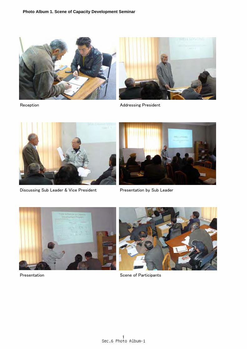
Photo Album 1. Scene of Capacity Development Seminar
Reception Addressing President
Discussing Sub Leader & Vice President Presentation by Sub Leader
Presentation Scene of Participants
1Sec.6 Photo Album-1
Photo Album 1. Scene of Capacity Development Seminar
2Sec.6 Photo Album-2
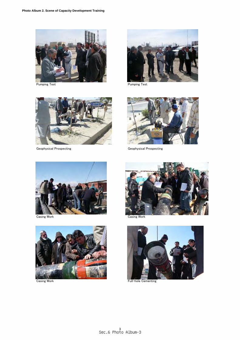
Photo Album 2. Scene of Capacity Development Training
Pumping Test Pumping Test
Geophysical Prospecting Geophysical Prospecting
Casing Work Casing Work
Casing Work Full-hole Cementing
3Sec.6 Photo Album-3
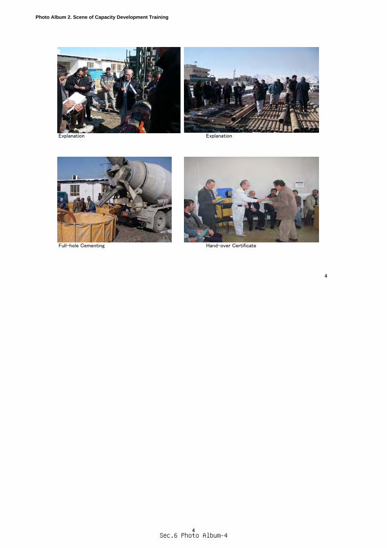
Photo Album 2. Scene of Capacity Development Training
Explanation Explanation
Full-hole Cementing Hand-over Certificate
4
4Sec.6 Photo Album-4