machine for industrial applications r 944 c - … · machine for industrial applications r 944 c...
TRANSCRIPT
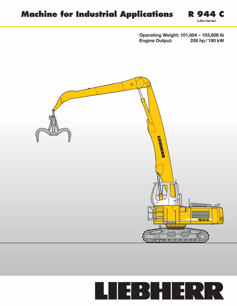
Machine for Industrial Applications R 944 Clitronic̀
Operating Weight: 101,604 – 103,808 lbEngine Output: 258 hp / 190 kW
2 R 944 C Litronic Machine for Industrial Applications
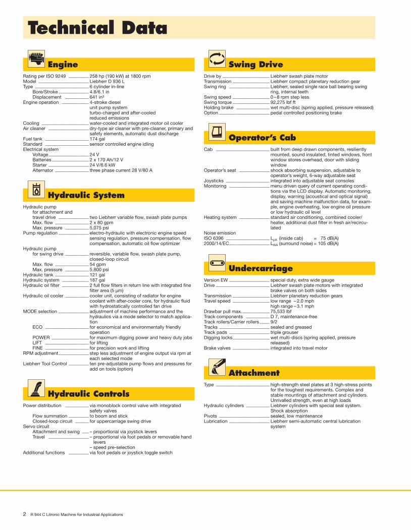
Technical Data
EngineRating per ISO 9249 ____________ 258 hp (190 kW) at 1800 rpmModel ______________________________ Liebherr D 936 LType ________________________________ 6 cylinder in-line
Bore/Stroke __________________ 4.8/6.1 inDisplacement ______________ 641 in3
Engine operation ________________ 4-stroke dieselunit pump systemturbo-charged and after-cooledreduced emissions
Cooling ____________________________ water-cooled and integrated motor oil coolerAir cleaner ________________________ dry-type air cleaner with pre-cleaner, primary and
safety elements, automatic dust dischargeFuel tank __________________________ 174 galStandard __________________________ sensor controlled engine idlingElectrical system
Voltage________________________ 24 VBatteries ______________________ 2 x 170 Ah/12 VStarter ________________________ 24 V/6.6 kWAlternator ____________________ three phase current 28 V/80 A
Swing DriveDrive by ____________________________ Liebherr swash plate motorTransmission ______________________ Liebherr compact planetary reduction gearSwing ring ________________________ Liebherr, sealed single race ball bearing swing
ring, internal teethSwing speed ______________________ 0 – 8 rpm step lessSwing torque ______________________ 92,275 lbf ftHolding brake ____________________ wet multi-disc (spring applied, pressure released)Option ______________________________ pedal controlled positioning brake
Operator’s CabCab ________________________________ built from deep drawn components, resiliently
mounted, sound insulated, tinted windows, frontwindow stores overhead, door with sliding window
Operator’s seat __________________ shock absorbing suspension, adjustable to operator’s weight, 6-way adjustable seat
Joysticks __________________________ integrated into adjustable seat consolesMonitoring ________________________ menu driven query of current operating condi-
tions via the LCD display. Automatic monitoring,display, warning (acoustical and optical signal)and saving machine malfunction data, for exam-ple, engine overheating, low engine oil pressureor low hydraulic oil level
Heating system __________________ standard air conditioning, combined cooler/heater, additional dust filter in fresh air/recircu -lated
Noise emissionISO 6396 __________________________ LpA (inside cab) = 75 dB(A)2000/14/EC________________________ LWA (surround noise) = 105 dB(A)
UndercarriageVersion EW ________________________ special duty, extra wide gaugeDrive ________________________________ Liebherr swash plate motors with integrated
brake valves on both sidesTransmission ______________________ Liebherr planetary reduction gearsTravel speed ______________________ low range – 2.0 mph
high range – 3.1 mphDrawbar pull max. ________________ 75,533 lbfTrack components ______________ D 7, maintenance-freeTrack rollers/Carrier rollers ______ 9/2Tracks ______________________________ sealed and greasedTrack pads ________________________ triple grouserDigging locks______________________ wet multi-discs (spring applied, pressure
released)Brake valves ______________________ integrated into travel motor
AttachmentType ________________________________ high-strength steel plates at 3 high-stress points
for the toughest requirements. Complex and stable mountings of attachment and cylinders.Unrivalled strength, even at high loads
Hydraulic cylinders ______________ Liebherr cylinders with special seal system.Shock absorption
Pivots ______________________________ sealed, low maintenanceLubrication ________________________ Liebherr semi-automatic central lubrication
system
Hydraulic ControlsPower distribution ______________ via monoblock control valve with integrated
safety valvesFlow summation ____________ to boom and stickClosed-loop circuit ________ for uppercarriage swing drive
Servo circuitAttachment and swing ____ – proportional via joystick leversTravel ________________________ – proportional via foot pedals or removable hand
levers– speed pre-selection
Additional functions ____________ via foot pedals or joystick toggle switch
Hydraulic SystemHydraulic pump
for attachment andtravel drive __________________ two Liebherr variable flow, swash plate pumpsMax. flow ____________________ 2 x 80 gpmMax. pressure ______________ 5,075 psi
Pump regulation __________________ electro-hydraulic with electronic engine speedsensing regulation, pressure compensation, flowcompensation, automatic oil flow optimizer
Hydraulic pumpfor swing drive ______________ reversible, variable flow, swash plate pump,
closed-loop circuitMax. flow ____________________ 54 gpmMax. pressure ______________ 5,800 psi
Hydraulic tank ____________________ 121 galHydraulic system ________________ 187 galHydraulic oil filter ________________ 2 full flow filters in return line with integrated fine
filter area (5 µm)Hydraulic oil cooler ______________ cooler unit, consisting of radiator for engine
coolant with after-cooler core, for hydraulic fluidwith hydrostatically controlled fan drive
MODE selection __________________ adjustment of machine performance and thehydraulics via a mode selector to match applica-tion
ECO __________________________ for economical and environmentally friendly operation
POWER ______________________ for maximum digging power and heavy duty jobsLIFT __________________________ for liftingFINE __________________________ for precision work and lifting
RPM adjustment__________________ step less adjustment of engine output via rpm ateach selected mode
Liebherr Tool Control ____________ ten pre-adjustable pump flows and pressures foradd on tools (option)
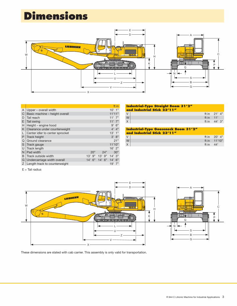
Dimensions
R 944 C Litronic Machine for Industrial Applications 3
L
Z
V
X
D
B
K
HW
P
U
A
S
G
N
C
Q
E
ft inA Upper – overall width 10’ 1”C Basic machine – height overall 11’11”D Tail reach 11’ 7”E Tail swing 11’ 7”H Height – engine hood 9’ 6”K Clearance under counterweight 4’ 4”L Center idler to center sprocket 13’ 1”P Track height 3’ 8”Q Ground clearance 21”S Track gauge 11’10”U Track length 16’ 2”N Pad width 20” ’24” ’30”B Track outside width 13’ 9” 13’ 9” 14’ 3”G Undercarriage width overall 14’ 6” 14’ 6” 14’ 6”Z Length track to counterweight 19’ 7”
E = Tail radius
L
Z
V
X
D
B
K
HW
P
U
A
S
G
N
C
Q
E
Industrial-Type Straight Boom 31’2”and Industrial Stick 23’11”V ft in 21’ 4”W ft in 11’ ”X ft in 44’ 3”
Industrial-Type Gooseneck Boom 31’2”and Industrial Stick 23’11”V ft in 20’ 4”W ft in 11’10”X ft in 44’ ”
These dimensions are stated with cab carrier. This assembly is only valid for transportation.

VarioLiftPlusVariable Boom Mounting Positions for Optimised Lift Capacities
4 R 944 C Litronic Machine for Industrial Applications
Hole B
Hole 3
Hole 2
Hole A
Version 2A
2A
2A
3B
3A
3B
with the same working range with a different working range
Kinematic variant 2A:Increased lift capacities above ground levelKinematic variant 3B:Increased lift capacities below ground leveland when working at extended reach
Kinematic variant 3A:Altered range curve with additional reachdepth, e.g. for unloading from ships
Kinematic variant 3D:Increased lift capacities below ground leveland when working at extended reach
Kinematic variant 3C:Altered range curve with additional reachdepth, e.g. for unloading from ships
Version 3D
Hole D
Hole C
Hole 3
Hole 2
3D
3D
3C
with a different working range
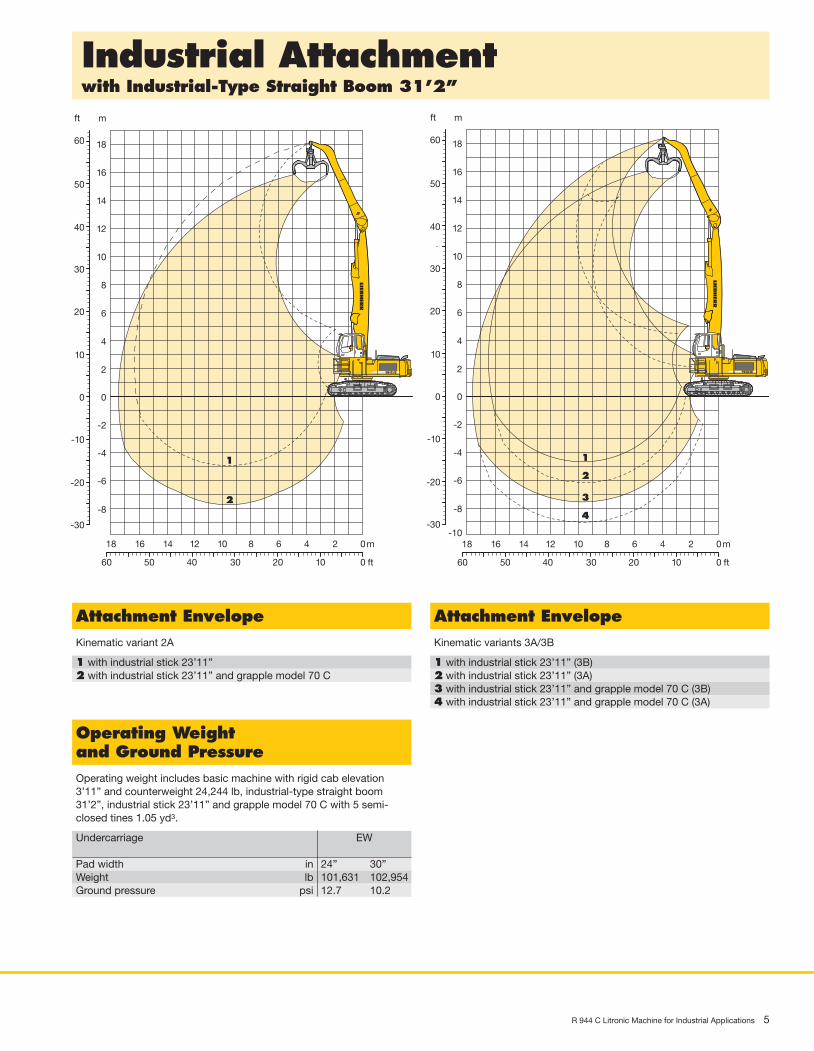
Industrial Attachmentwith Industrial-Type Straight Boom 31’2”
R 944 C Litronic Machine for Industrial Applications 5
0m24681012
0 ft10203040
1
2
14
50
0
-2
-4
-6
-8
2
4
6
8
10
12
m
14
0
-10
-20
10
20
30
ft
40
50
16
-30
16
1860
18
60
0m24681012
0 ft10203040
1
2
14
50
0
-2
-4
-6
-8
2
4
6
8
10
12
m
14
0
-10
-20
10
20
30
ft
40
50
16
-30
16
1860
18
60
3
4
-10
Attachment EnvelopeKinematic variants 3A/3B
1 with industrial stick 23’11” (3B)2 with industrial stick 23’11” (3A)3 with industrial stick 23’11” and grapple model 70 C (3B)4 with industrial stick 23’11” and grapple model 70 C (3A)
Attachment EnvelopeKinematic variant 2A
1 with industrial stick 23’11”2 with industrial stick 23’11” and grapple model 70 C
Operating Weightand Ground PressureOperating weight includes basic machine with rigid cab elevation3’11” and counterweight 24,244 lb, industrial-type straight boom31’2”, industrial stick 23’11” and grapple model 70 C with 5 semi- closed tines 1.05 yd3.
Undercarriage EW
Pad width in 24” 30”Weight lb 101,631 102,954Ground pressure psi 12.7 10.2
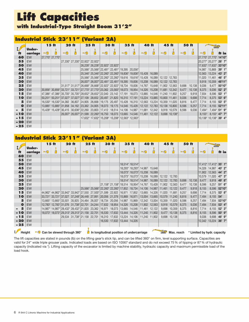
Lift Capacitieswith Industrial-Type Straight Boom 31’2”
6 R 944 C Litronic Machine for Industrial Applications
Industrial Stick 23’11” (Variant 2A)15 ft 20 ft 25 ft 30 ft 35 ft 40 ft 45 ft 50 ft
Under-ft carriage ft in60 EW55 EW50 EW45 EW40 EW35 EW30 EW25 EW20 EW15 EW10 EW5 EW0 EW
– 5 EW– 10 EW– 15 EW– 20 EW– 25 EW
27,770* 27,770* 27,770* 27,770* 14’10”27,330* 27,330* 22,922* 22,922* 20,277* 20,277* 26’ 7”
26,228* 26,228* 22,922* 22,922* 17,632* 17,632* 33’10”25,566* 25,566* 22,481* 22,481* 19,395. 20,056* 14,987. 15,869. 39’ 1”25,346* 25,346* 22,260* 22,260* 19,836* 19,836* 15,428 16,089 12,563. 13,224. 43’ 2”25,566* 25,566* 22,260* 22,260* 19,616. 19,616* 15,428 16,089 12,122 12,783. 11,020. 11,461. 46’ 5”26,007* 26,007* 22,481* 22,481* 19,395. 19,836. 15,208 16,089 12,122 12,783. 9,918. 10,359. 48’11”
31,517* 31,517* 26,668* 26,668* 22,922* 22,922* 18,734. 19,836. 14,767 15,648 11,902 12,563. 9,698 10,138 9,036. 9,477. 50’10”30,856* 30,856* 33,721* 33,721* 27,770* 27,770* 23,362. 23,583* 18,073. 18,954. 14,326 15,208 11,681 12,342. 9,477 10,138 8,375. 9,036. 52’ 2”47,386* 47,386* 35,705* 35,705* 28,652* 28,652* 22,040. 23,142. 17,191. 18,073. 13,885 14,546 11,240 11,902. 9,257 9,918 7,934. 8,596. 53’ 1”50,251* 50,251* 37,027* 37,027* 27,109. 28,652. 20,497. 21,820. 16,310. 17,191. 13,224 13,885 10,800 11,461. 9,036 9,698 7,714. 8,375. 53’ 6”16,530* 16,530* 34,382. 36,807. 24,905. 26,668. 19,175. 20,497. 15,428. 16,310. 12,563 13,224 10,359 11,020. 8,816 9,477 7,714. 8,155. 53’ 5”13,885* 13,885* 31,958. 34,162. 23,362. 24,905. 18,073. 19,175. 14,546. 15,428. 12,122 12,783 10,138 10,800. 8,596 9,257 7,714. 8,155. 52’11”15,428* 15,428* 30,415. 30,636* 22,260. 23,803. 17,412. 18,514. 14,106. 14,987. 11,681 12,342 9,918 10,579. 8,596 9,036 7,494* 7,494* 51’ 9”
26,007* 26,007* 21,599. 22,260* 16,750. 18,073. 13,665. 14,546. 11,461 12,122 9,698 10,138* 8,155* 8,155* 47’ 7”17,632* 17,632* 15,208* 15,208* 12,563* 12,563* 10,138* 10,138* 39’ 4”
Industrial Stick 23’11” (Variant 3A)15 ft 20 ft 25 ft 30 ft 35 ft 40 ft 45 ft 50 ft
Under-ft carriage ft in60 EW55 EW50 EW45 EW40 EW35 EW30 EW25 EW20 EW15 EW10 EW5 EW0 EW
– 5 EW– 10 EW– 15 EW– 20 EW– 25 EW
18,514* 18,514* 17,412* 17,412* 35’ 1”18,293* 18,293* 14,987 15,648 14,326. 14,987. 40’ 2”18,073* 18,073* 15,208 16,089 11,902. 12,563. 44’ 2”18,073* 18,073* 15,208 16,089 12,122 12,783 10,579. 11,020. 47’ 3”18,514* 18,514* 14,987 16,089 12,122 12,783 9,698 10,138 9,477. 9,918. 49’ 8”
21,158* 21,158* 18,514. 18,954* 14,767 15,428 11,902 12,563 9,477 10,138 8,596. 9,257. 51’ 6”25,566* 25,566* 22,260* 22,260* 17,852. 18,734. 14,106 14,987 11,461 12,122 9,477 9,918 8,155. 8,596. 52’10”
44,962* 44,962* 33,942* 33,942* 27,550. 27,500* 21,599. 22,922. 16,971. 17,852. 13,665 14,326 11,020 11,681 9,257 9,698 7,714. 8,375. 53’ 8”33,721* 33,721* 37,027. 37,248* 26,448. 27,991. 20,056. 21,379. 15,869. 16,971. 13,004 13,665 10,579 11,240 8,816 9,477 7,494. 8,155. 54’ ”13,665* 13,665* 33,501. 35,925. 24,464. 26,007. 18,734. 20,056. 14,987. 15,869. 12,342 13,004 10,359 11,020 8,596 9,257 7,494. 7,934. 53’10”12,783* 12,783* 31,076. 31,738* 22,701. 24,244. 17,632. 18,954. 14,326. 15,208. 11,902 12,563 9,918 10,579 8,375 9,036 7,494. 7,934. 53’ 4”14,987* 14,987* 28,432* 28,432* 21,820. 23,362. 16,971. 18,073. 13,665. 14,546. 11,461 12,122 9,698 10,359 8,375 8,816 7,714. 8,155. 52’ 3”18,073* 18,073* 29,313* 29,313* 21,158. 22,701. 16,530. 17,632. 13,444. 14,326. 11,240 11,902 9,477 10,138 8,375 8,816 8,155. 8,596. 50’ 9”
29,534. 31,738* 21,158. 22,701. 16,310. 17,632. 13,224. 14,106. 11,240 11,902 9,698 10,138 9,036. 9,698. 46’ 9”16,530. 17,632. 13,444. 14,326. 12,342. 13,224. 36’ 7”
Height Can be slewed through 360° In longitudinal position of undercarriage Max. reach * Limited by hydr. capacity
The lift capacities are stated in pounds (lb) on the lifting gear’s stick tip, and can be lifted 360° on firm, level supporting surface. Capacities arevalid for 24” wide triple grouser pads. Indicated loads are based on ISO 10567 standard and do not exceed 75 % of tipping or 87 % of hydrauliccapacity (indicated via *). Lifting capacity of the excavator is limited by machine stability, hydraulic capacity and maximum permissible load of theload hook.

Lift Capacitieswith Industrial-Type Straight Boom 31’2”
R 944 C Litronic Machine for Industrial Applications 7
Industrial Stick 23’11” (Variant 3B)15 ft 20 ft 25 ft 30 ft 35 ft 40 ft 45 ft 50 ft
Under-ft carriage ft in60 EW55 EW50 EW45 EW40 EW35 EW30 EW25 EW20 EW15 EW10 EW5 EW0 EW
– 5 EW– 10 EW– 15 EW– 20 EW– 25 EW
22,260* 22,260* 19,836* 19,836* 28’ 3”20,718* 20,718* 18,954* 18,954* 17,852* 17,852* 17,412* 17,412* 35’ 1”19,836* 19,836* 18,293* 18,293* 16,971* 16,971* 14,987 15,648 14,326. 14,987. 40’ 2”
18,073* 18,073* 16,750* 16,750* 15,428 15,869* 11,902. 12,563. 44’ 2”19,836* 19,836* 18,073* 18,073* 16,750* 16,750* 15,428 15,648* 12,122 12,783 10,579. 11,020. 47’ 3”20,718* 20,718* 18,734* 18,734* 17,191* 17,191* 15,208 15,869* 12,122 12,783 9,698 10,138 9,477. 9,918. 49’ 8”
25,126* 25,126* 22,040* 22,040* 19,616* 19,616* 17,632* 17,632* 14,767 15,428 11,902 12,563 9,698 10,138 8,596. 9,257. 51’ 6”31,297* 31,297* 28,211* 28,211* 23,803* 23,803* 20,718* 20,718* 17,852. 18,514* 14,106 14,987 11,461 12,122 9,477 9,918 8,155. 8,596. 52’10”41,656* 41,656* 31,738* 31,738* 25,787* 25,787* 21,599. 22,040* 16,971. 17,852. 13,665 14,326 11,020 11,681 9,257 9,698 7,714. 8,375. 53’ 8”33,721* 33,721* 35,264* 35,264* 26,448. 27,770* 20,277. 21,379. 15,869. 16,971. 13,004 13,665 10,579 11,240 9,036 9,477 7,494. 8,155. 54’ ”13,665* 13,665* 33,501. 35,925. 24,464. 26,007. 18,734. 20,056. 14,987. 16,089. 12,342 13,004 10,359 11,020 8,596 9,257 7,494. 7,934. 53’10”12,783* 12,783* 31,297. 31,738. 22,922. 24,464. 17,852. 18,954. 14,326. 15,208. 11,902 12,563 9,918 10,579 8,375 9,036 7,494. 7,934. 53’ 4”14,987* 14,987* 28,432* 28,432* 21,820. 23,362. 16,971. 18,073. 13,665. 14,767. 11,461 12,122 9,698 10,359 8,375 8,816 7,714. 8,375. 51’ 9”
29,313* 29,313* 21,379. 22,922. 16,530. 17,632. 13,444. 14,326. 11,240 11,902 9,477 10,138 8,816. 9,477. 47’ 3”16,530. 17,632. 13,224. 14,326. 11,902. 12,783. 37’ 5”
Height Can be slewed through 360° In longitudinal position of undercarriage Max. reach * Limited by hydr. capacity
The lift capacities are stated in pounds (lb) on the lifting gear’s stick tip, and can be lifted 360° on firm, level supporting surface. Capacities arevalid for 24” wide triple grouser pads. Indicated loads are based on ISO 10567 standard and do not exceed 75 % of tipping or 87 % of hydrauliccapacity (indicated via *). Lifting capacity of the excavator is limited by machine stability, hydraulic capacity and maximum permissible load of theload hook.
8 R 944 C Litronic Machine for Industrial Applications
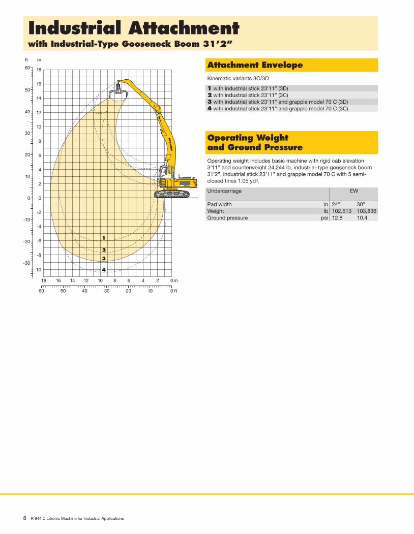
Industrial Attachmentwith Industrial-Type Gooseneck Boom 31’2”
0m24681012
0 ft10203040
1
2
14
50
0
-2
-4
-6
-8
2
4
6
8
10
12
m
14
0
-10
-20
10
20
30
ft
40
50
16
-30
16
1860
18
60
-10
3
4
Attachment EnvelopeKinematic variants 3C/3D
1 with industrial stick 23’11” (3D)2 with industrial stick 23’11” (3C)3 with industrial stick 23’11” and grapple model 70 C (3D)4 with industrial stick 23’11” and grapple model 70 C (3C)
Operating Weightand Ground PressureOperating weight includes basic machine with rigid cab elevation3’11” and counterweight 24,244 lb, industrial-type gooseneck boom31’2”, industrial stick 23’11” and grapple model 70 C with 5 semi- closed tines 1.05 yd3.
Undercarriage EW
Pad width in 24” 30”Weight lb 102,513 103,836Ground pressure psi 12.8 10.4
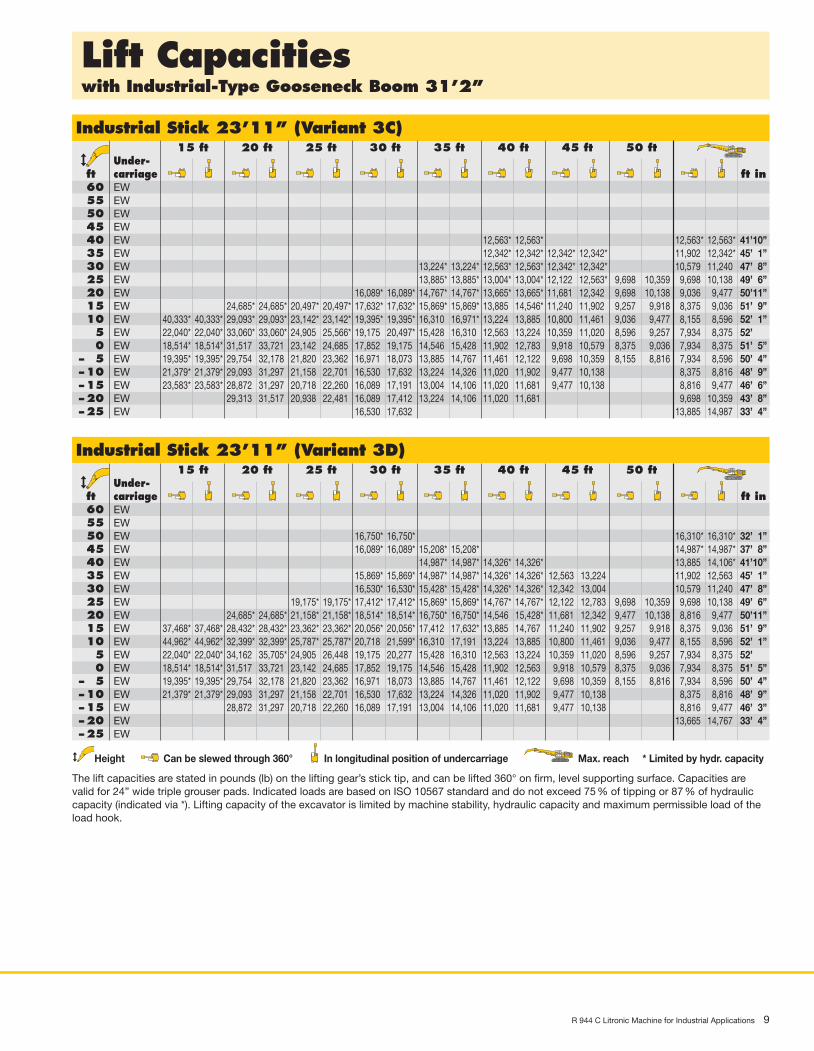
Lift Capacitieswith Industrial-Type Gooseneck Boom 31’2”
R 944 C Litronic Machine for Industrial Applications 9
Industrial Stick 23’11” (Variant 3C)15 ft 20 ft 25 ft 30 ft 35 ft 40 ft 45 ft 50 ft
Under-ft carriage ft in60 EW55 EW50 EW45 EW40 EW35 EW30 EW25 EW20 EW15 EW10 EW5 EW0 EW
– 5 EW– 10 EW– 15 EW– 20 EW– 25 EW
12,563* 12,563* 12,563* 12,563* 41’10”12,342* 12,342* 12,342* 12,342* 11,902. 12,342* 45’ 1”
13,224* 13,224* 12,563* 12,563* 12,342* 12,342* 10,579. 11,240. 47’ 8”13,885* 13,885* 13,004* 13,004* 12,122. 12,563* 9,698 10,359 9,698. 10,138. 49’ 6”
16,089* 16,089* 14,767* 14,767* 13,665* 13,665* 11,681. 12,342. 9,698 10,138 9,036. 9,477. 50’11”24,685* 24,685* 20,497* 20,497* 17,632* 17,632* 15,869* 15,869* 13,885. 14,546* 11,240. 11,902. 9,257 9,918 8,375. 9,036. 51’ 9”
40,333* 40,333* 29,093* 29,093* 23,142* 23,142* 19,395* 19,395* 16,310. 16,971* 13,224. 13,885. 10,800. 11,461. 9,036 9,477 8,155. 8,596. 52’ 1”22,040* 22,040* 33,060* 33,060* 24,905. 25,566* 19,175. 20,497* 15,428. 16,310. 12,563. 13,224. 10,359. 11,020. 8,596 9,257 7,934. 8,375. 52’ ”18,514* 18,514* 31,517. 33,721. 23,142. 24,685. 17,852. 19,175. 14,546. 15,428. 11,902. 12,783. 9,918. 10,579. 8,375 9,036 7,934. 8,375. 51’ 5”19,395* 19,395* 29,754. 32,178. 21,820. 23,362. 16,971. 18,073. 13,885. 14,767. 11,461. 12,122. 9,698. 10,359. 8,155 8,816 7,934. 8,596. 50’ 4”21,379* 21,379* 29,093. 31,297. 21,158. 22,701. 16,530. 17,632. 13,224. 14,326. 11,020. 11,902. 9,477. 10,138. 8,375. 8,816. 48’ 9”23,583* 23,583* 28,872. 31,297. 20,718. 22,260. 16,089. 17,191. 13,004. 14,106. 11,020. 11,681. 9,477. 10,138. 8,816. 9,477. 46’ 6”
29,313. 31,517. 20,938. 22,481. 16,089. 17,412. 13,224. 14,106. 11,020. 11,681. 9,698. 10,359. 43’ 8”16,530. 17,632. 13,885. 14,987. 33’ 4”
Industrial Stick 23’11” (Variant 3D)15 ft 20 ft 25 ft 30 ft 35 ft 40 ft 45 ft 50 ft
Under-ft carriage ft in60 EW55 EW50 EW45 EW40 EW35 EW30 EW25 EW20 EW15 EW10 EW5 EW0 EW
– 5 EW– 10 EW– 15 EW– 20 EW– 25 EW
16,750* 16,750* 16,310* 16,310* 32’ 1”16,089* 16,089* 15,208* 15,208* 14,987* 14,987* 37’ 8”
14,987* 14,987* 14,326* 14,326* 13,885. 14,106* 41’10”15,869* 15,869* 14,987* 14,987* 14,326* 14,326* 12,563 13,224 11,902. 12,563. 45’ 1”16,530* 16,530* 15,428* 15,428* 14,326* 14,326* 12,342 13,004 10,579. 11,240. 47’ 8”
19,175* 19,175* 17,412* 17,412* 15,869* 15,869* 14,767* 14,767* 12,122 12,783 9,698 10,359 9,698. 10,138. 49’ 6”24,685* 24,685* 21,158* 21,158* 18,514* 18,514* 16,750* 16,750* 14,546. 15,428* 11,681 12,342 9,477 10,138 8,816. 9,477. 50’11”
37,468* 37,468* 28,432* 28,432* 23,362* 23,362* 20,056* 20,056* 17,412. 17,632* 13,885. 14,767. 11,240 11,902 9,257 9,918 8,375. 9,036. 51’ 9”44,962* 44,962* 32,399* 32,399* 25,787* 25,787* 20,718. 21,599* 16,310. 17,191. 13,224. 13,885. 10,800 11,461 9,036 9,477 8,155. 8,596. 52’ 1”22,040* 22,040* 34,162. 35,705* 24,905. 26,448. 19,175. 20,277. 15,428. 16,310. 12,563. 13,224. 10,359 11,020 8,596 9,257 7,934. 8,375. 52’ ”18,514* 18,514* 31,517. 33,721. 23,142. 24,685. 17,852. 19,175. 14,546. 15,428. 11,902. 12,563. 9,918 10,579 8,375 9,036 7,934. 8,375. 51’ 5”19,395* 19,395* 29,754. 32,178. 21,820. 23,362. 16,971. 18,073. 13,885. 14,767. 11,461. 12,122. 9,698 10,359 8,155 8,816 7,934. 8,596. 50’ 4”21,379* 21,379* 29,093. 31,297. 21,158. 22,701. 16,530. 17,632. 13,224. 14,326. 11,020. 11,902. 9,477 10,138 8,375. 8,816. 48’ 9”
28,872. 31,297. 20,718. 22,260. 16,089. 17,191. 13,004. 14,106. 11,020. 11,681. 9,477 10,138 8,816. 9,477. 46’ 3”13,665. 14,767. 33’ 4”
Height Can be slewed through 360° In longitudinal position of undercarriage Max. reach * Limited by hydr. capacity
The lift capacities are stated in pounds (lb) on the lifting gear’s stick tip, and can be lifted 360° on firm, level supporting surface. Capacities arevalid for 24” wide triple grouser pads. Indicated loads are based on ISO 10567 standard and do not exceed 75 % of tipping or 87 % of hydrauliccapacity (indicated via *). Lifting capacity of the excavator is limited by machine stability, hydraulic capacity and maximum permissible load of theload hook.
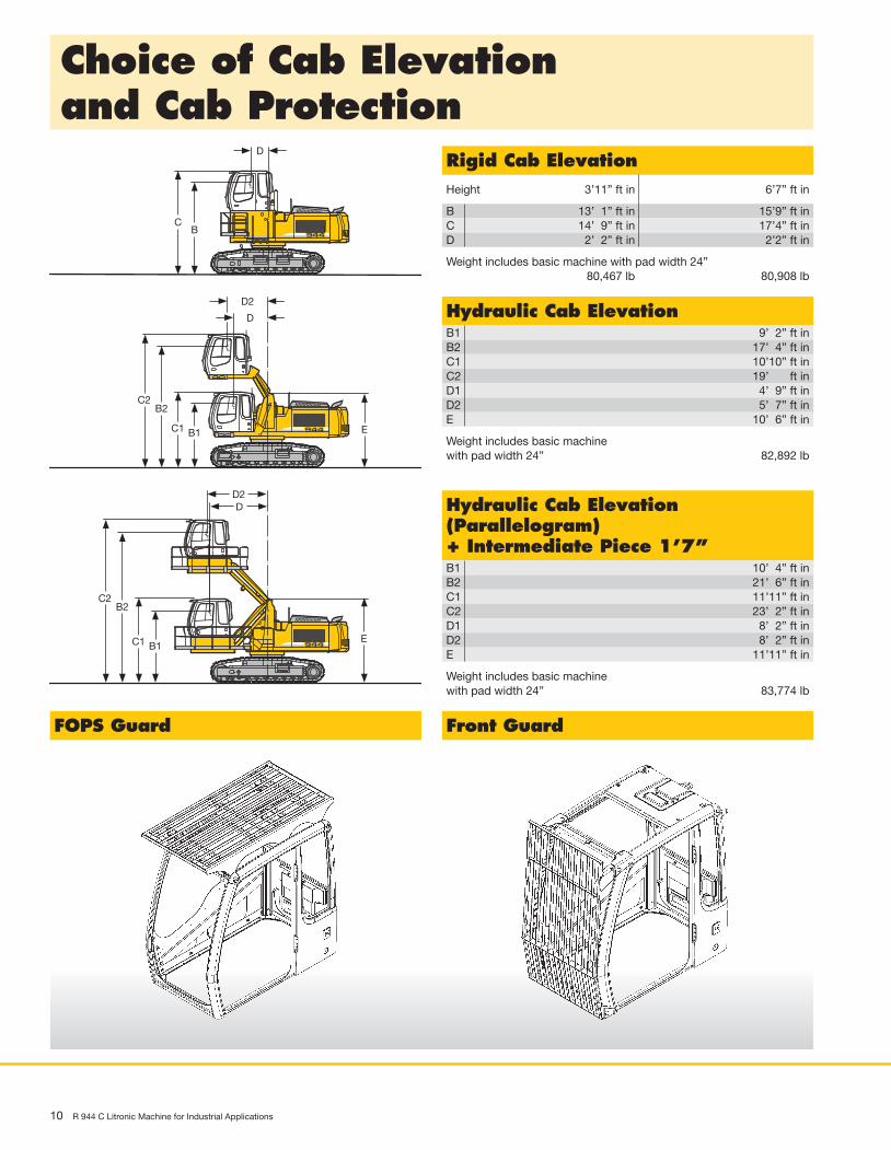
Choice of Cab Elevationand Cab Protection
10 R 944 C Litronic Machine for Industrial Applications
D
BC
D
B1C1
D2
B2C2
E
D
B1C1
D2
B2C2
E
Rigid Cab ElevationHeight 3’11” ft in 6’7” ft in
B 13’ 1” ft in 15’9” ft inC 14’ 9” ft in 17’4” ft inD 2’ 2” ft in 2’2” ft in
Weight includes basic machine with pad width 24”80,467 lb 80,908 lb
Hydraulic Cab Elevation(Parallelogram)+ Intermediate Piece 1’7”B1 10’ 4” ft inB2 21’ 6” ft inC1 11’11” ft inC2 23’ 2” ft inD1 8’ 2” ft inD2 8’ 2” ft inE 11’11” ft in
Weight includes basic machinewith pad width 24” 83,774 lb
Hydraulic Cab ElevationB1 9’ 2” ft inB2 17’ 4” ft inC1 10’10” ft inC2 19’ ” ft inD1 4’ 9” ft inD2 5’ 7” ft inE 10’ 6” ft in
Weight includes basic machinewith pad width 24” 82,892 lb
FOPS Guard Front Guard

R 944 C Litronic Machine for Industrial Applications 11
Variety of Tools
Multiple Tine Grapples open tines semi-closed tines closed tines
Grapple Model 69 Capacity yd3 1.05 1.44 1.05 1.44 1.05 1.44(4 tines) Weight lb 2,965 3,075 3,384 3,615 4,188 4,541Grapple Model 70 C Capacity yd3 1.05 1.44 1.05 1.44 1.05 1.44(5 tines) Weight lb 3,273 3,505 3,758 4,100 4,299 4,398
Crane Hook with SuspensionMax.load lb 27,557Height with suspension ft in 3’Total weight lb 211
For further information see color brochure “Add-on tools for material-handling technology”. To operate a magnet the installation of a generator isrequired; please contact your Liebherr dealer or the factory for further information.
Electromagnets with SuspensionMagnet information on request

Liebherr Construction Equipment Co.4100 Chestnut Avenue, Newport News, VA 23607, USA� (7 57) 2 45 52 51, Fax (7 57) 9 28 87 01www.liebherr.us, E-Mail: [email protected]
Prin
ted
in G
erm
any
by
Gei
selm
ann
RG
-BK
LF
R/S
P 1
0356
699-
1-01
.08
Illu
stra
tions
and
dat
a m
ay d
iffer
from
sta
ndar
d e
qui
pm
ent.
Sub
ject
to
chan
ge w
ithou
t no
tice.
All
ind
icat
ed lo
ads
are
bas
ed in
acc
ord
ance
with
ISO
924
8.
Equipment
S = Standard, O = Option
Options and/or special attachments, supplied by vendors other than Liebherr, are only to be installed with theknowledge and approval of Liebherr to retain warranty.
Undercarriage S O
Two-speed travel •Track guides on idler end •Life time lubricated track rollers •Travel drive completely integrated into the undercarriage frame •Tracks sealed and greased •Track guides at sprocket and in center •Reinforced base-plate center-piece •Conversion kit – Track D 7 to D 7 G •
Operator’s Cab S O
Roof hatch •Tinted windows •Right window made of one piece (without post) •Door with sliding window •Rain hood over front window opening •Wiper/washer •Emergecy exit rear window •Sun roller blind •Seat and consoles independently adjustable(6-way adjustable seat) •Storage tray •Closed storage space •Coat hook •Removable customized foot mat •Dome light •Inside rear mirror •Cigarette lighter and ashtray •Seat belt •Mechanical hour meters, readable from outside the cab •Displays for engine operating condition •Automatic air conditioning with defroster •Preparation for radio installation •Stereo radio •Electric cooler •Auxiliary heating •Additional flood lights •Wiper in lower front window •Roof window wiper •Bullet proof window (fixed installation – can not be opened) •FOPS Protection •Air pressure operator seat with heating and head-rest •Electronic theft protection •Beacon •Extinguisher •
Uppercarriage S O
Engine hood with lift cylinder •Lockable tool box •Handrails, non slip surfaces •Tool kit •Maintenance-free swing brake lock •Maintenance-free HD-batteries •Main switch for electric circuit •Sound insulation •Electric fuel tank filler pump •Foot pedal swing positioning brake •Extended tool kit •Customized colors •
Hydraulics S O
Electronic pump regulation •Stepless work mode selector •Pressure storage for controlled lowering of attachments withengine turned off •Hydraulic tank shut-off valve •Pressure compensation •Flow compensation •Filter with integrated fine filter area (5 µm) •Pressure test ports •Additional hydraulic circuits •Bio-degradable hydr. oil •Filter for secondary circuit •
Attachment S O
Flood lights •Hydr. lines for clam operation in stick •Sealed pivots •Liebherr semi-automatic central lubrication system •Safety check valves on hoist cylinder, regenerative •Safety check valves on stick cylinder, regenerative •Hose quick connection •Cylinders with shock absorber •Industrial-type gooseneck sticks with remote hydraulic pinpuller •Safety lift hook •Liebherr line of clams •Liebherr fully-automatic central lubrication system •Customized colors •Overload warning device •
Engine S O
Unit pump system •Turbo-charged and after-cooled, reduced emissions •Dry-type air cleaner w/pre-cleaner, main and safety element •Sensor controlled engine idling •Engine cold starting aid •