m5311 nb-iot at command specificationiot.10086.cn/uploads/file/product/20190216/m5311...m5311 at...
TRANSCRIPT

M5311 AT Command Interface Specification
NB-IoT Series
Version:2.1
Date:2018-12-27
China Mobile IoT Company Limited http://iot.10086.cn
© 2018 CMCC IoT Comany.

M5311 AT Command Specification
Document Revision History
Revision Date Notes
1.0 2018-01-26 Initial release
1.1 2018-02-22 Change tcp/ip network commands
1.2 2018-04-04 Add CMCC OneNET commands
1.3 2018-04-23 Add AT*MNBIOTEVENT command
1.4 2018-05-16 Add AT+CMSYSCTRL command
1.5 2018-05-29 Add AT+CPOF/AT+CMRB/AT*MDPDNP command
Change HTTP/HTTPS commands
2.0 2018-06-28
Remove unsupported AT command and Add AT Commands special for CMIOT/AT+CRLA
Change HTTP/HTTPS commands
Updated AT+CMSYSCTRL/AT+CTZR
2.1 2018-12-29
Add AT+CMADC/AT+COLDRB/AT+DNSSER/AT+TAUAC commands
Add AT*WAKETIME/AT*ENTERSLEEP commands
Add AT*CMBAND set command, support to lock/select Band
Add AT+IPR=0, support atuo baud rate.
Change AT*CMBAND? result code form ‘Current Band’ to ‘Configured Band’.
Change AT+GPIO commands, change parameter <gpio_id> to <gpio_pin>, from 9/10 to 34/35.
Fix the Incorrect time-zone of the result AT+CCLK?
Change +HTTPEER command
Add +HTTPDICONN command
Change +HTTPNMIH command
Change +HTTPNMIC command
Change AT+IPRD result data from Synchronous way to
Add AT+CLPLMN
Remove AT^SYSINFO
Change AT+EPORT command
Add AT*EDRXCFG to support eDRX PTW configuration(Only the M5311_CM version is supported.)

M5311 AT Command Specification
Table of Contents
Content 1. General Command Line specifications .................................................................................................................. 1
1.1. Manufacturer Specific Responses to AT Commands .................................................................................. 1 1.2. SMS Handling Details ................................................................................................................................. 1
1.3.1. SMS PDU Mode ........................................................................................................................ 1 1.3.2. Handling of SMS Status Reports ............................................................................................... 1
2. AT Command Overview ........................................................................................................................................ 2 2.1. Command Syntax ....................................................................................................................................... 2 2.2. Basic Syntax ............................................................................................................................................... 2
2.2.1. Parameter Syntax ..................................................................................................................... 2 2.2.2. Extended Syntax ....................................................................................................................... 2
2.3. Result Codes............................................................................................................................................... 3 2.4. CME Error Codes ........................................................................................................................................ 3
2.4.1. General CME Error Codes ......................................................................................................... 3 2.4.2. CRSM/CSIM CME Error Codes .................................................................................................. 4 2.4.3. +CSCS CME Error Codes ............................................................................................................ 5 2.4.4. +CPOL CME Error Codes ........................................................................................................... 5 2.4.5. Miscellaneous Proprietary CME Error Codes ............................................................................ 5 2.4.6. PSD and Packet Domain CME Error Codes ............................................................................... 6 2.4.7. *ENGINFO CME Error Codes .................................................................................................. 10 2.4.8. CMS Error Codes .................................................................................................................... 10
2.5. General Examples .................................................................................................................................... 12
3. AT Command Interface ....................................................................................................................................... 14 3.1. Guidance on AT Command Syntax Definitions ......................................................................................... 14 3.2. Supported AT Commands According to V.250 ......................................................................................... 15
3.2.1. Overview ................................................................................................................................ 15 3.2.2. Detailed Description of Commands ........................................................................................ 16 3.2.2.1. +++ ......................................................................................................................................... 16 3.2.2.2. ATE ......................................................................................................................................... 16 3.2.2.3. ATH ........................................................................................................................................ 17 3.2.2.4. ATI .......................................................................................................................................... 17 3.2.2.5. ATL ......................................................................................................................................... 17 3.2.2.6. ATM ....................................................................................................................................... 18 3.2.2.7. ATN1 ...................................................................................................................................... 18 3.2.2.8. ATO ........................................................................................................................................ 18 3.2.2.9. ATQ ........................................................................................................................................ 19 3.2.2.10. ATS0 ....................................................................................................................................... 19 3.2.2.11. ATS1 ....................................................................................................................................... 20 3.2.2.12. ATS2 ....................................................................................................................................... 20 3.2.2.13. ATS3 ....................................................................................................................................... 21 3.2.2.14. ATS4 ....................................................................................................................................... 21 3.2.2.15. ATS5 ....................................................................................................................................... 22 3.2.2.16. ATS6 ....................................................................................................................................... 22 3.2.2.17. ATS7 ....................................................................................................................................... 22 3.2.2.18. ATS8 ....................................................................................................................................... 23 3.2.2.19. ATS10 ..................................................................................................................................... 23 3.2.2.20. ATS12 ..................................................................................................................................... 24 3.2.2.21. ATS25 ..................................................................................................................................... 25 3.2.2.22. ATS95 ..................................................................................................................................... 25

M5311 AT Command Specification
3.2.2.23. ATV ......................................................................................................................................... 26 3.2.2.24. ATX ......................................................................................................................................... 26 3.2.2.25. ATZ ......................................................................................................................................... 27 3.2.2.26. AT&C ...................................................................................................................................... 27 3.2.2.27. AT&D ...................................................................................................................................... 28 3.2.2.28. AT&F ...................................................................................................................................... 28 3.2.2.29. AT&K ...................................................................................................................................... 28 3.2.2.30. AT&V ...................................................................................................................................... 29 3.2.2.31. AT&W ..................................................................................................................................... 29 3.2.2.32. AT+DR .................................................................................................................................... 30 3.2.2.33. AT+DS ..................................................................................................................................... 30 3.2.2.34. AT+GCAP ................................................................................................................................ 31 3.2.2.35. AT+GMI .................................................................................................................................. 31 3.2.2.36. AT+GMM ................................................................................................................................ 32 3.2.2.37. AT+GMR ................................................................................................................................. 32 3.2.2.38. AT+GOI ................................................................................................................................... 32 3.2.2.39. AT+GSN .................................................................................................................................. 33 3.2.2.40. AT+ICF .................................................................................................................................... 33 3.2.2.41. AT+IFC .................................................................................................................................... 34 3.2.2.42. AT+ILRR .................................................................................................................................. 35 3.2.2.43. AT+IPR .................................................................................................................................... 36 3.2.2.44. ATD*99#................................................................................................................................. 36
3.3. Supported AT Commands According to 3GPP TS 27.007 ......................................................................... 39 3.3.1. Overview ................................................................................................................................ 39 3.3.2. Detailed Descriptions of Commands ...................................................................................... 40 3.3.2.1. AT+CCLK ................................................................................................................................. 40 3.3.2.2. AT+CEER ................................................................................................................................. 41 3.3.2.3. AT+CFUN ................................................................................................................................ 41 3.3.2.4. AT+CGACT .............................................................................................................................. 42 3.3.2.5. AT+CGATT .............................................................................................................................. 44 3.3.2.6. AT+CGDATA ........................................................................................................................... 44 3.3.2.7. AT+CGDCONT ......................................................................................................................... 45 3.3.2.8. AT+CGMI ................................................................................................................................ 47 3.3.2.9. AT+CGMM .............................................................................................................................. 47 3.3.2.10. AT+CGMR ............................................................................................................................... 48 3.3.2.11. AT+CGOI ................................................................................................................................. 48 3.3.2.12. AT+CGPADDR ......................................................................................................................... 48 3.3.2.13. AT+CGREG .............................................................................................................................. 49 3.3.2.14. AT+CEREG .............................................................................................................................. 50 3.3.2.15. AT+CGCONTRDP ..................................................................................................................... 52 3.3.2.16. AT+CGSN ................................................................................................................................ 54 3.3.2.17. AT+CIMI ................................................................................................................................. 54 3.3.2.18. AT+CLCK ................................................................................................................................. 55 3.3.2.19. AT+CMAR ............................................................................................................................... 56 3.3.2.20. AT+CMEE ................................................................................................................................ 56 3.3.2.21. AT+CMUX ............................................................................................................................... 57 3.3.2.22. AT+COPS ................................................................................................................................ 58 3.3.2.23. AT+CESQ ................................................................................................................................ 60 3.3.2.24. AT+CSQ .................................................................................................................................. 61 3.3.2.25. AT+CPIN ................................................................................................................................. 62 3.3.2.26. AT+CPOL................................................................................................................................. 63 3.3.2.27. AT+CPWD ............................................................................................................................... 64 3.3.2.28. AT+CR ..................................................................................................................................... 65 3.3.2.29. AT+CREG ................................................................................................................................ 66 3.3.2.30. AT+CSIM ................................................................................................................................. 67 3.3.2.31. AT+CRSM ............................................................................................................................... 68

M5311 AT Command Specification
3.3.2.32. AT+CSCS ................................................................................................................................. 69 3.3.2.33. AT+CTZR ................................................................................................................................. 69 3.3.2.34. AT+CTZU................................................................................................................................. 70 3.3.2.35. AT+CPLS ................................................................................................................................. 71 3.3.2.36. AT+CPSMS .............................................................................................................................. 71 3.3.2.37. AT+CIPCA ............................................................................................................................... 72 3.3.2.38. AT+CCIOTOPT ......................................................................................................................... 74 3.3.2.39. AT+CEDRXS ............................................................................................................................ 75 3.3.2.40. AT+CEDRXRDP ........................................................................................................................ 76 3.3.2.41. AT+CGAPNRC ......................................................................................................................... 77 3.3.2.42. AT+CSCON .............................................................................................................................. 78 3.3.2.43. AT+CCHO ................................................................................................................................ 79 3.3.2.44. AT+CCHC ................................................................................................................................ 79 3.3.2.45. AT+CGLA ................................................................................................................................ 80 3.3.2.46. AT+CRLA ................................................................................................................................. 81 3.3.2.47. AT+CPINR ............................................................................................................................... 82 3.3.2.48. AT+CGPIAF ............................................................................................................................. 83 3.3.2.49. AT+CGEREP ............................................................................................................................ 85 3.3.2.50. AT+CGDEL .............................................................................................................................. 88 3.3.2.51. AT+CGAUTH ........................................................................................................................... 88
3.4. AT Commands According to 3GPP TS 27.005 for SMS .............................................................................. 90 3.4.1. Overview ................................................................................................................................ 90 3.4.2. Concatenated SMSs................................................................................................................ 90 3.4.2.1. Concatenated SMSs and AT+CSMP ........................................................................................ 90 3.4.3. Detailed Descriptions of Commands ...................................................................................... 92 3.4.3.1. AT+CMGD............................................................................................................................... 92 3.4.3.2. AT+CMGF ............................................................................................................................... 93 3.4.3.3. AT+CMGL ............................................................................................................................... 93 3.4.3.4. AT+CMGR ............................................................................................................................... 95 3.4.3.5. AT+CMGS ............................................................................................................................... 98 3.4.3.6. AT+CMGW ............................................................................................................................. 99 3.4.3.7. AT+CMSS .............................................................................................................................. 100 3.4.3.8. AT+CMGC ............................................................................................................................. 101 3.4.3.9. AT+CNMI .............................................................................................................................. 102 3.4.3.10. AT+CPMS .............................................................................................................................. 104 3.4.3.11. AT+CRES ............................................................................................................................... 105 3.4.3.12. AT+CSAS ............................................................................................................................... 105 3.4.3.13. AT+CSCA ............................................................................................................................... 106 3.4.3.14. AT+CSDH .............................................................................................................................. 106 3.4.3.15. AT+CSMP .............................................................................................................................. 107 3.4.3.16. AT+CSMS .............................................................................................................................. 108 3.4.3.17. AT+CNMA ............................................................................................................................. 108 3.4.3.18. AT+CMMS ............................................................................................................................ 109
3.5. AT Commands Special for CMIOT .......................................................................................................... 111 3.5.1. Overview .............................................................................................................................. 111 3.5.2. Detailed Description of Commands ...................................................................................... 111 3.5.2.1. AT+HVER .............................................................................................................................. 111 3.5.2.2. AT+SWVER ........................................................................................................................... 112 3.5.2.3. AT+CPOF............................................................................................................................... 112 3.5.2.4. AT+CMRB ............................................................................................................................. 113 3.5.2.5. AT+COLDRB .......................................................................................................................... 114 3.5.2.6. AT+GPIO ............................................................................................................................... 114 3.5.2.7. AT+SM .................................................................................................................................. 116 3.5.2.8. AT+EPORT ............................................................................................................................ 117 3.5.2.9. AT+CMADC ........................................................................................................................... 119 3.5.2.10. AT+CMSYSCTRL .................................................................................................................... 120

M5311 AT Command Specification
3.5.2.11. AT+TAUAC ............................................................................................................................ 121 3.5.2.12. AT+ICCID .............................................................................................................................. 122 3.5.2.13. AT+CLPLMN .......................................................................................................................... 123 3.5.2.14. AT*ENGINFO ........................................................................................................................ 123 3.5.2.15. AT*FRCLLCK ......................................................................................................................... 126 3.5.2.16. AT*SPCHSC ........................................................................................................................... 127 3.5.2.17. AT*CGDEFCONT ................................................................................................................... 128 3.5.2.18. AT*PLNMURI ........................................................................................................................ 129 3.5.2.19. AT*NBIOTDT ........................................................................................................................ 130 3.5.2.20. AT*NBIOTRAI ....................................................................................................................... 131 3.5.2.21. AT*HOMENW ...................................................................................................................... 131 3.5.2.22. AT*CMSPN ........................................................................................................................... 132 3.5.2.23. AT*CMUNSOL ...................................................................................................................... 132 3.5.2.24. AT*CMBAND ........................................................................................................................ 133 3.5.2.25. AT*MATWAKEUP ................................................................................................................. 134 3.5.2.26. AT*SLEEP .............................................................................................................................. 134 3.5.2.27. AT*WAKETIME ..................................................................................................................... 135 3.5.2.28. AT*ENTERSLEEP ................................................................................................................... 136 3.5.2.29. AT*EDRXCFG ........................................................................................................................ 137 3.5.2.30. AT*MDPDNP ........................................................................................................................ 139 3.5.2.31. AT^SYSCONFIG ..................................................................................................................... 140 3.5.2.32. AT^CARDMODE .................................................................................................................... 141 3.5.2.33. AT^SPN................................................................................................................................. 141 3.5.2.34. *SMPUKBLKD Unsolicited Indication .................................................................................... 142 3.5.2.35. *ATREADY ............................................................................................................................ 143
4. Network Related Proprietary AT Command Interface ...................................................................................... 145 4.1. PDN Command ....................................................................................................................................... 145
4.1.1 AT+EGACT ............................................................................................................................ 145 4.2. Network Command ................................................................................................................................ 147
4.2.1 AT+PING ............................................................................................................................... 147 4.2.1 AT+DNSSER .......................................................................................................................... 148 4.2.2 AT+CMDNS ........................................................................................................................... 149 4.2.3 AT+IPSTART .......................................................................................................................... 149 4.2.4 AT+IPLPORT .......................................................................................................................... 150 4.2.5 AT+IPSEND ........................................................................................................................... 151 4.2.6 AT+IPCLOSE .......................................................................................................................... 152 4.2.7 AT+IPRCFG ........................................................................................................................... 152 4.2.8 AT+IPRD ............................................................................................................................... 153 4.2.9 +IPNMI ................................................................................................................................. 154 4.2.10 AT+IPKPA.............................................................................................................................. 154 4.2.11 AT+IPSACK ............................................................................................................................ 154 4.2.12 AT+IPSTATUS ........................................................................................................................ 155 4.2.13 Create a TCP socket example ............................................................................................... 155 4.2.14 Create a UDP socket example .............................................................................................. 157
4.3. MQTT Command .................................................................................................................................... 158 4.3.1 AT+MQTTCFG ....................................................................................................................... 158 4.3.2 AT+MQTTOPEN .................................................................................................................... 158 4.3.3 AT+MQTTSTAT ..................................................................................................................... 159 4.3.4 AT+MQTTSUB ....................................................................................................................... 159 4.3.5 AT+MQTTPUB ...................................................................................................................... 160 4.3.6 AT+MQTTUNSUB.................................................................................................................. 160 4.3.7 AT+MQTTDISC ...................................................................................................................... 161 4.3.8 AT+MQTTDEL ....................................................................................................................... 161 4.3.9 AT+MQTTTO......................................................................................................................... 161 4.3.10 +MQTTPUBLSH ..................................................................................................................... 161 4.3.11 +MQTTTO ............................................................................................................................. 162
M5311 AT Command Specification
4.4. HTTP/HTTPS Command .......................................................................................................................... 162 4.4.1 AT+HTTPCREATE .................................................................................................................. 162 4.4.2 AT+HTTPCFG ........................................................................................................................ 163 4.4.3 AT+HTTPHEADER ................................................................................................................. 163 4.4.4 AT+HTTPCONTENT ............................................................................................................... 164 4.4.5 AT+HTTPSEND ...................................................................................................................... 165 4.4.6 AT+HTTPCLOSE..................................................................................................................... 165 4.4.7 +HTTPNMIH ......................................................................................................................... 165 4.4.8 +HTTPNMIC .......................................................................................................................... 166 4.4.9 +HTTPDICONN ...................................................................................................................... 166 4.4.10 +HTTPERR ............................................................................................................................. 166 4.4.11 HTTP/HTTPS Example ........................................................................................................... 167
4.5. TLS Command ........................................................................................................................................ 170 4.5.1. AT+TLSCFG ........................................................................................................................... 170 4.5.2. AT+TLSCONN ........................................................................................................................ 172 4.5.3. AT+TLSCLOSE ....................................................................................................................... 173 4.5.4. AT+TLSSEND ......................................................................................................................... 173 4.5.5. AT+TLSRECV ......................................................................................................................... 174 4.5.6. AT+TLSRMOD ....................................................................................................................... 175 4.5.7. +TLSNMI ............................................................................................................................... 176 4.5.8. +TLSERR................................................................................................................................ 177
4.6. OneNET Command ................................................................................................................................. 177 4.6.1. AT+MIPLCREATE .................................................................................................................. 177 4.6.2. AT+MIPLDEL ......................................................................................................................... 178 4.6.3. AT+MIPLOPEN ...................................................................................................................... 178 4.6.4. AT+MIPLUPDATE .................................................................................................................. 179 4.6.5. AT+MIPLADDOBJ.................................................................................................................. 179 4.6.6. AT+MIPLDELOBJ ................................................................................................................... 180 4.6.7. AT+MIPLCLOSE ..................................................................................................................... 180 4.6.8. AT+MIPLNOTIFY ................................................................................................................... 180 4.6.9. AT+MIPLREADRSP ................................................................................................................ 181 4.6.10. AT+MIPLWRITERSP .............................................................................................................. 182 4.6.11. AT+MIPLEXECUTERSP .......................................................................................................... 183 4.6.12. AT+MIPLDISCOVERRSP ........................................................................................................ 184 4.6.13. AT+MIPLOBSERVERSP .......................................................................................................... 184 4.6.14. AT+MIPLPARAMETERRSP ..................................................................................................... 185 4.6.15. AT+MIPLVER ........................................................................................................................ 185
5. Appendix .......................................................................................................................................................... 187 5.1. Extended DRX parameters(3GPP TS 24.008) ......................................................................................... 187 5.2. GPRS Timer (3GPP TS 24.008) ................................................................................................................ 191
5.2.1 GPRS Timer .......................................................................................................................... 191 5.2.2 GPRS Timer 2 ........................................................................................................................ 191 5.2.3 GPRS Timer 3 ........................................................................................................................ 192

M5311 AT Command Specification
Definitions and Abbreviations
3GPP 3
rd Generation Partnership Project
AID Application Identifier AT Attention; this two-character abbreviation is always used to start a command line to
be sent from TE to TA ATCI AT Command Interface BCD Binary Coded Decimal BER-TLV Basic Encoding Rule - TLV DF Dedicated File DO Data Object EF Elementary File FCP File Control Parameters GSM Global System for Mobile communications IMSI International Mobile Subscriber Identity MCC Mobile Country Code ME Mobile Equipment MMI Man Machine Interface MNC Mobile Network Code MT Mobile Termination PIN Personal Identification Number PS_DO PIN Status Data Object RFU Reserved for Future Use SIM Subscriber Identity Module SFI Short EF Identifier
STK SIM Toolkit TA Terminal Adaptor (e.g. a GSM data card equal to DCE Data Circuit terminating Equipment) TE Terminal Equipment, e.g. a computer (equal to DTE; Data Terminal Equipment) TLV Tag Length Value
UE User Equipment UICC Universal Integrated Circuit Card USIM Universal Subscriber Identity Module B-TID Bootstrapping Transaction Identifier GBA Generic Bootstrapping Architecture GBA_ME ME-based GBA GBA_U GBA with UICC-based enhancements TMGI Temporary Mobile Group Identity

M5311 AT Command Specification
1 /192
1. General Command Line specifications
1.1. Manufacturer Specific Responses to AT Commands
A number of AT commands require generating a manufacturer specific response. These commands are listed below:
ATI
AT+GMM/AT+CGMM
AT+GMR/AT+CGMR
AT+GMI/AT+CGMI
AT+GOI/AT+CGOI
AT+HVER/AT+SWVER
Note:The result of AT+HVER/AT+SWVER is the current version. Other commands return the result to the factory factory version.
1.2. SMS Handling Details
1.3.1. SMS PDU Mode
The M5311 data services software supports two type of PDU mode:
PDU mode according to 3GPP standard 27.005
PDU mode backward compatible with data solutions currently on the market (called TPDU only).
Both methods have been implemented to allow more compatibility with SMS programs, which can be downloaded off the Internet. The software can be configured to use either method by using the profile AT+CSMS command. The table below gives details of the two methods:
PDU Mode AT+CSMS Description
3GPP Standard 0 PDU mode implemented exactly as described in 3GPP TS 27.005.
3GPP Standard 1 The same as above, but acknowledgement command must be sent, as described in 3GPP TS 27.005.
TPDU only 128 PDU mode implemented such that only the SMS TPDU is sent, stored, and displayed. The Service Centre Address information is omitted.
1.3.2. Handling of SMS Status Reports
SMS status reports are handled differently in a number of areas to standard SMS messages. This section describes the specifics of how they are dealt with within the modem software.
M5311 AT Command Specification
2 /192
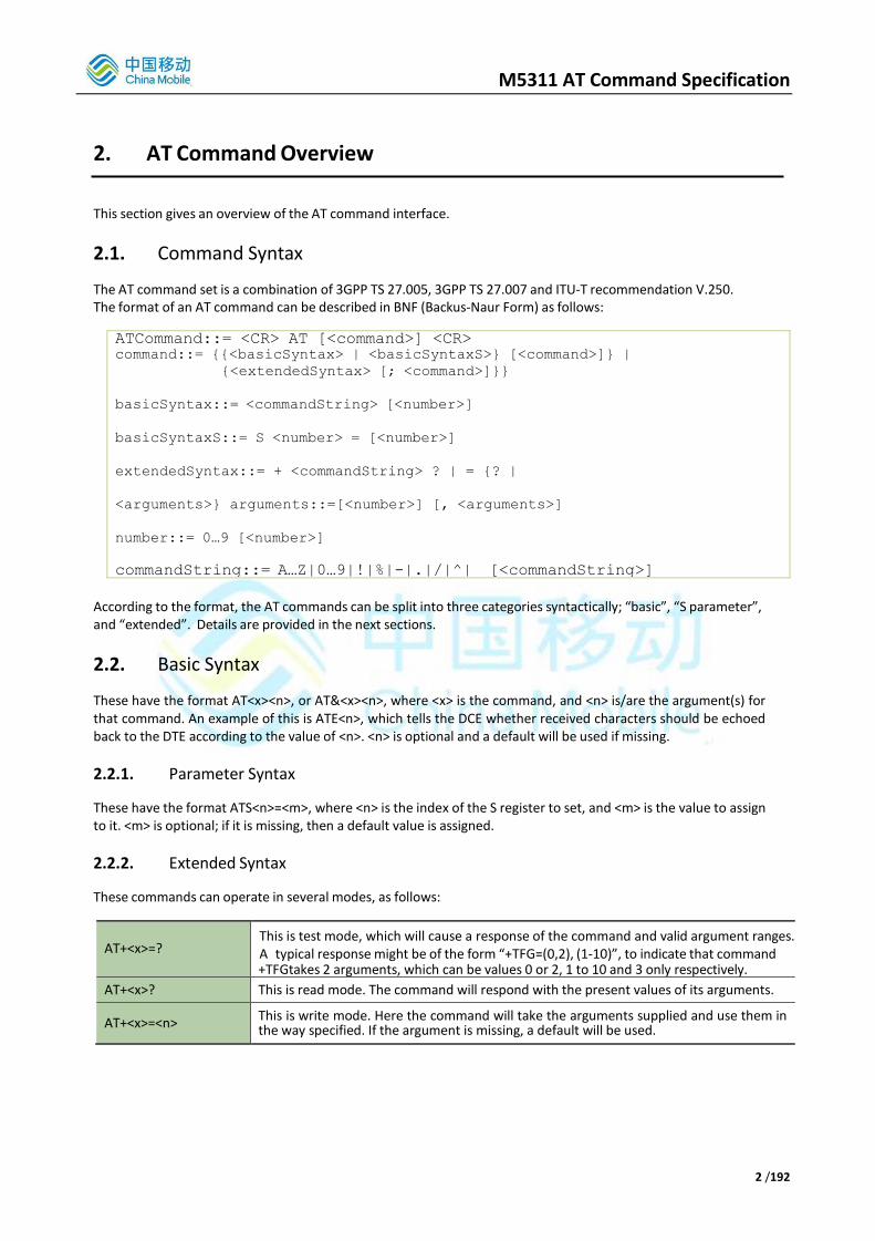
2. AT Command Overview
This section gives an overview of the AT command interface.
2.1. Command Syntax
The AT command set is a combination of 3GPP TS 27.005, 3GPP TS 27.007 and ITU-T recommendation V.250. The format of an AT command can be described in BNF (Backus-Naur Form) as follows:
ATCommand::= <CR> AT [<command>] <CR> command::= {{<basicSyntax> | <basicSyntaxS>} [<command>]} |
{<extendedSyntax> [; <command>]}}
basicSyntax::= <commandString> [<number>]
basicSyntaxS::= S <number> = [<number>]
extendedSyntax::= + <commandString> ? | = {? |
<arguments>} arguments::=[<number>] [, <arguments>]
number::= 0…9 [<number>]
commandString::= A…Z|0…9|!|%|-|.|/|^|_ [<commandString>]
According to the format, the AT commands can be split into three categories syntactically; “basic”, “S parameter”, and “extended”. Details are provided in the next sections.
2.2. Basic Syntax
These have the format AT<x><n>, or AT&<x><n>, where <x> is the command, and <n> is/are the argument(s) for that command. An example of this is ATE<n>, which tells the DCE whether received characters should be echoed back to the DTE according to the value of <n>. <n> is optional and a default will be used if missing.
2.2.1. Parameter Syntax
These have the format ATS<n>=<m>, where <n> is the index of the S register to set, and <m> is the value to assign to it. <m> is optional; if it is missing, then a default value is assigned.
2.2.2. Extended Syntax
These commands can operate in several modes, as follows:
AT+<x>=? This is test mode, which will cause a response of the command and valid argument ranges. A typical response might be of the form “+TFG=(0,2), (1-10)”, to indicate that command +TFG takes 2 arguments, which can be values 0 or 2, 1 to 10 and 3 only respectively.
AT+<x>? This is read mode. The command will respond with the present values of its arguments.
AT+<x>=<n> This is write mode. Here the command will take the arguments supplied and use them in the way specified. If the argument is missing, a default will be used.

M5311 AT Command Specification
3 /192
2.3. Result Codes
Verbose Result Code Short Result Code Description
OK 0 Indicates execution of a valid command
CONNECT 1 A connection has been established; ATCI is moving from command state to online data state
RING 2 Incoming call indication
NO CARRIER 3 A call attempt has failed.
ERROR 4 Command error. The parser will execute as much of the command as it can until an error is detected, when it will abort the process and respond with this message.
2.4. CME Error Codes
2.4.1. General CME Error Codes
Verbose CME Error Code Short CME
Code Description
Phone failure 0 Phone failure
No connection to phone 1 No connection to phone
Phone-adaptor link reserved 2 The requested connection is not allowed due to one or more other active connections.
Operation not allowed 3 The operation requested is not allowed (generally operations performed in a restrictive state i.e. fixed dialing)
Operation not supported 4 The operation requested is not supported (generally parameters in operations which aren’t supported)
PH-SIM PIN required 5 PIN required for the SIM the phone is locked to
PH-FSIM PIN required 6 PIN required for the First SIM the phone is locked to
PH-FSIM PUK required 7 PUK required for the First SIM the phone is locked to
SIM not inserted 10 Operation not allowed: SIM Card hasn’t been inserted (or has been removed)
SIM PIN required 11 Operation not allowed: SIM PIN required (possibly as a result of the pending command failing)
SIM PUK required 12 Operation not allowed: SIM PUK required (possibly as a result of the pending command failing)
SIM failure 13 Operation not allowed: SIM fault has occurred (possibly as a result of the pending command failing)
SIM busy 14 Operation not allowed: SIM is being used by another procedure
SIM wrong 15 Operation not allowed: MEP check has failed
Incorrect password 16 The incorrect password for the operation has been provided
SIM PIN2 required 17 Operation not allowed: SIM PIN2 required (possibly as a result of the pending command failing)
SIM PUK2 required 18 Operation not allowed: SIM PUK2 required

M5311 AT Command Specification
4 /192
(possibly as a result of the pending command failing)
Memory full 20 Operation failed due to SIM memory being full
invalid index 21 Operation failed – invalid memory index supplied
not found 22 The requested index (call, memory) has not been found
memory failure 23 NVRAM read/write has failed
text string too long 24 The entered text string is longer than allowed
invalid characters in text string 25 Invalid characters in string (i.e. characters in expected numeric string)
dial string too long 26 The entered dial string is longer than allowed
invalid characters in dial string 27 Invalid characters in dial string
no network service 30 Operation can’t be performed due to ME not currently camped on network
network timeout 31 Operation failed: network timed out
network not allowed - emergency calls only
32 Only emergency calls are currently allowed (due to either requiring PIN/PUK or reduced network coverage)
network personalization PIN required 40 Operation failed: require MEP PIN code
network personalization PUK required
41 Operation failed: require MEP PUK code
network subset personalization PIN required
42 Operation failed: require MEP PIN code
network subset personalization PUK required
43 Operation failed: require MEP PUK code
service provider personalization PIN required
44 Operation failed: require MEP PIN code
service provider personalization PUK required
45 Operation failed: require MEP PUK code
corporate personalization PIN required
46 Operation failed: require MEP PIN code
corporate personalization PUK required
47 Operation failed: require MEP PUK code
hidden key required 48 Operation failed: require hidden key entry (Release 5 / 3G only)
Incorrect Parameters 50 Incorrect parameters entered.
Unknown 100 An unknown error has occurred
2.4.2. CRSM/CSIM CME Error Codes
Verbose CME Error Code Short CME Code Description
invalid command length 749 Invalid command length provided to CSIM
invalid input string 750 Invalid command string provided to CSIM
command not allowed for 3G SIM 751 SIM command not allowed on 3G SIM (Release 5 only)
Invalid <pathid> parameter 752 Invalid pathid for SIM
missing required command parameter
753 Command type parameter missing from CRSM command
invalid SIM command 754 Command type parameter for CRSM invalid
invalid File Id 755 FileID parameter for CRSM invalid

M5311 AT Command Specification
5 /192
missing required P1/2/3 parameter 756 P1/2/3 for CRSM command missing
invalid P1/2/3 parameter 757 P1/2/3 for CRSM command invalid
missing required command data 758 Command Data for CRSM command missing
invalid characters in command data 759 Command Data for CRSM command invalid
2.4.3. +CSCS CME Error Codes
Verbose CME Error Code Short CME Code Description
+CSCS type not supported 737 The CSCS mode specified is not supported
+CSCS type not found 738 The CSCS mode specified is not supported
2.4.4. +CPOL CME Error Codes
Verbose CME Error Code Short CME Code Description
must include <format> with <oper> 741 Operator format parameter is missing
incorrect <oper> format 742 Operator data is in incorrect format
<oper> length too long 743 Operator data is too long
SIM full 744 PLMN data cannot be written as the PLMN store is full
unable to change PLMN list 745 The SIM PLMN list cannot be changed since CPOL cannot access it
network operator not recognized 746 Operator specified is not recognized
access technology missing 747 Specified access technology missing
access technology not supported 748 Specified access technology not supported
2.4.5. Miscellaneous Proprietary CME Error Codes
Verbose CME Error Code Short CME Code Description
SIM toolkit menu has not been configured
720 The SIM toolkit menu has not been configured
SIM toolkit already in use 721 The SIM toolkit is already in use
SIM toolkit not enabled 722 SIM toolkit not enabled on the SIM
MMI profile not updated 724 The MMI profile has not been updated
invalid SIM toolkit proactive command ID
725 An invalid SIM toolkit proactive command ID was received
invalid SIM proactive command response data
726 Invalid SIM toolkit proactive command response data received
invalid input value 765 One or more input values are invalid
unsupported value or mode 766 One or more input values are unsupported
operation failed 767 Operation failed
multiplexer already active 768 Multiplexer already active – cannot be changed or re- activated
unable to get control of required module
769 Command cannot be executed since a required resource cannot be allocated
SIM invalid - network reject 770 The SIM has been rejected by the network
SIM powered down 772 The SIM has been powered down
SIM File not present 773 The SIM file is not present

M5311 AT Command Specification
6 /192
invalid input value 794 One or more input values are invalid
No valid GId 795 No valid GId
2.4.6. PSD and Packet Domain CME Error Codes
Note that “PSD” in the Verbose CME Error Code refers to any Packet Domain error.
Verbose CME Error Code Short CME Code Description
illegal MS 103 Illegal MS
illegal ME 106 Illegal ME
PSD services not allowed 107 Attach not allowed due to SIM/network restrictions
PLMN not allowed 111 Operation failed due to incorrect PLMN
location area not allowed 112 Operation failed due to incorrect LA
roaming not allowed in this location area
113 Operation failed due to incorrect LA
service option not supported 132 Operation failed due to service not being supported
requested service option not subscribed
133 Operation failed due to service not being subscribed
service option temporarily out of order
134 Operation failed due to service option being temporarily out of order
Unspecified GPRS error 148 Operation failed due to unknown Packet Domain error
PDP authentication failure 149 Operation failed due to PDP authentication failure
invalid mobile class 150 Operation failed due to invalid ME operation class
Last PDN Disconnection not allowed #49
151 UE attempted to disconnect the last PDN connection.
PSD - activation rejected by GGSN 577 Activation failed due to rejection by Gateway GPRS Support Node
PSD - unspecified activation rejection
578 Activation failed for unspecified reason
PSD - bad code or protocol rejection 579 PPP failure due to bad code or protocol rejection
PSD - can't modify address 580 PPP failure, address cannot be modified
PSD - CHAP close 581 PPP failure – CHAP close
PSD - profile (cid) currently unavailable
582 CID is currently in use by another entity
PSD - a profile (cid) is currently active
583 An active context currently exists
PSD - combined services not allowed 584 Combined services are not allowed
PSD - conditional IE error 585 Conditional IE error
PSD - context activation rejected 586 PPP failure – context activation rejected
PSD - duplicate TI received 587 Duplicate Transaction Identifier received
PSD - feature not supported 588 Feature not supported
PSD - service not available 589 PPP Failure – either service not available or device powering down
PSD - unknown IE from network 590 IE non-existent or not implemented
PSD - implicitly detached 591 EMM Implicitly detached
PSD - insufficient resources 592 Insufficient resources to complete action
PSD - invalid activation state (0-1) 593 An operation has been carried out where the

M5311 AT Command Specification
7 /192
context is in the incorrect state
PSD - invalid address length 594 PPP Failure – invalid address length
PSD - invalid character in address string
595 PPP Failure – invalid character in address string
PSD - invalid cid value 596 The supplied CID value is out of the allowed range
PSD - invalid dial string length 597 PPP Failure – invalid dial string length
PSD - mode value not in range 598 Invalid mode for Packet Domain event reporting
PSD - invalid MAND information 599 Invalid mandatory information
PSD - SMS service preference out of range
600 Invalid SMS service preference value supplied
PSD - invalid TI value 601 Invalid Transaction Identifier
PSD - IPCP negotiation timeout 602 PPP Failure – IPCP negotiation timeout
PSD - LCP negotiation timeout 603 PPP Failure – LCP negotiation timeout
PSD - LLC error 604 LLC error
PSD - LLC or SNDCP failure 605 LLC or SNDCP failure
PSD - lower layer failure 606 Lower layer failure
PSD - missing or unknown APN 607 Missing or unknown APN specified
PSD - mobile not ready 608 Mobile not ready
PSD - MS identity not in network 609 MS ID not in network
PSD - MSC temporarily not reachable
610 MSC temporarily not reachable
PSD - message incompatible with state
611 Message incompatible with state
PSD - message type incompatible with state
612 Message type incompatible with state
PSD - unknown message from network
613 Unknown message from network
PSD - NCP close 614 PPP Failure – NCP close
PSD - network failure 615 Network failure
PSD - no echo reply 616 PPP Failure – no echo reply
PSD - no free NSAPIs 617 PPP Failure – no free NSAPIs
PSD - processing of multiple cids not supported
618 Only a single CID may be active at any one time
PSD - no PDP context activated 619 No PDP context activated
PSD - normal termination 620 PPP Failure – normal termination
PSD - NSAPI already used 621 NSAPI already used
PSD - address element out of range 622 PPP Failure - address element out of range
PSD - PAP close 623 PPP Failure – PAP close
PSD - PDP context w/o TFT already activated
624 PPP Failure - context without TFT already activated
PSD - pdp type not supported 625 PPP Failure – invalid PDP type
PSD - peer refuses our ACCM 626 PPP Failure - peer refuses our ACCM
PSD - peer refuses our IP address 627 PPP Failure - peer refuses our IP address
PSD - peer refuses our MRU 628 PPP Failure - peer refuses our MRU
PSD - peer re-requested CHAP 629 PPP Failure - peer re-requested CHAP
PSD - profile (cid) not defined 630 Operation on an inactive/undefined CID
PSD - unspecified protocol error 631 Unspecified protocol error
PSD - QOS not accepted 632 PPP Failure - QOS not accepted

M5311 AT Command Specification
8 /192
PSD - QOS validation fail 633 PPP Failure - QOS validation fail
PSD - reactivation required 634 Reactivation required
PSD - regular deactivation 635 Regular deactivation
PSD - semantic error in TFT operation
636 Semantic error in TFT operation
PSD - semantic errors in packet filter 637 Semantic errors in packet filter
PSD - semantically incorrect message
638 Semantically incorrect message
PSD - service type not yet available 639 Service type not available
PSD - syntactical error in TFT operation
640 Syntactical error in TFT operation
GPRS - syntactical errors in packet filter
641 Syntactical errors in packet filter
PSD - too many RXJs 642 PPP Failure - too many RXJs
PSD - unknown PDP address or type 643 Unknown PDP address or type
PSD - unknown PDP context 644 Unknown PDP context
PSD - user authorization failed 645 User authorization failed
PSD - QOS invalid parameter 646 Invalid QoS parameters
PSD - FDN failure 647 FDN failure
PSD - bad pdp context parameters 649 Bad PDP context parameters
PSD - PDP context already active 650 PDP context already active
PSD - LCP termination negotiation timeout
651 PPP LCP termination negotiation timeout
more than one double colon in IPv6 address
652 IPV6 PDP context addressing error: more than one double colon
IPv6 address ended with part of an IPv4 address
653 IPV6 PDP context addressing error: IPv6 address ended with part of an IPv4 address
IPv6 address used dotted-decimal form outside an IPv4 address
654 IPV6 PDP context addressing error: IPv6 address used dotted-decimal form outside an IPv4 address
in an IPv6 address, a byte of an IPv4 address was too big, causing overflow
655 IPV6 PDP context addressing error: in an IPv6 address, a byte of an IPv4 address was too big, causing overflow
in an IPv6 address, a byte of an IPv4 address was missing
656 IPV6 PDP context addressing error: in an IPv6 address, a byte of an IPv4 address was missing
in an IPv6 address, a byte of an IPv4 address was more than 255
657 IPV6 PDP context addressing error: in an IPv6 address, a byte of an IPv4 address was more than 255
in an IPv6 address, a byte pair was more than hex ffff
658 IPV6 PDP context addressing error: in an IPv6 address, a byte pair was more than hex ffff
in an IPv6 address, a byte of an IPv4 address was too short or contained invalid characters
659 IPV6 PDP context addressing error: in an IPv6 address, a byte of an IPv4 address was too short or contained invalid characters
an IPv6 address was too short or contained invalid characters
660 IPV6 PDP context addressing error: an IPv6 address was too short or contained invalid characters
in an IPv6 address, a byte pair was too big, causing overflow
661 IPV6 PDP context addressing error: in an IPv6 address, a byte pair was too big, causing overflow
an IPv6 address started with a single colon
662 IPV6 PDP context addressing error: an IPv6 address started with a single colon
an IPv6 address ended with a single colon
663 IPV6 PDP context addressing error: an IPv6 address ended with a single colon

M5311 AT Command Specification
9 /192
an IPv6 address contained an IPv4 address other than at the end
664 IPV6 PDP context addressing error: an IPv6 address contained an IPv4 address other than at the end
an IPv6 address was too long 665 IPV6 PDP context addressing error: an IPv6 address was too long
an IPv6 address was followed by invalid characters
666 IPV6 PDP context addressing error: an IPv6 address was followed by invalid characters
PSD - operator Determined Barring 670 Operator has barred the PSD connection
PSD - activation rejected by GW or PDNGW
671 The activation was rejected by the Gateway or PDN Gateway
PSD – PTI already in use 672 NB-IOT PTI already in use
PSD – EPS Bearer Context without TFT already activated
673 EPS bearer context without a TFT has already been activated with the same bearer settings
PSD - PTI mismatch 674 PTI mismatched during EPS bearer procedure
PSD - PDN Type IPV4 only allowed 675 Only IPV4 type connections are allowed
PSD – PDN Type IPV6 only allowed 676 Only IPV6 type connection are allowed
PSD – single address bearers only allowed
677 Only single IP address (either IPV4 or IPV6) type connections allowed
PSD – ESM information not received 678 No information received at the ESM level
PSD – PDN connection does not exist
679 PDN connection referenced for bearer modification or deactivations non-existent
PSD – multiple PDN connection not allowed for one APN
680 Multiple PDN connections (primary contexts) cannot be made using the same APN on NB-IOT
PSD – collision with network initiated request
681 UE initiated operation clashed with network initiated operation
PSD – unsupported QCI value 682 QCI value not supported
PSD – invalid PTI value 683 PTI value is not valid
PSD – incompatible APN restriction value
684 APN restriction value not compatible
PSD – reactivation request 685 Network is requesting the UE to re-activate the PDN connection
LTE - IMSI unknown in HSS 690 UE not known (registered) in the HSS
LTE - illegal UE 691 Networks refused service to UE (ID failure or authentication failure)
LTE - EPS service not allowed 692 UE not allowed to operate EPS services
LTE - EPS and non EPS Service not allowed
693 UE not allowed to operate in EPS or non-EPS services
LTE - UE ID cannot be derived 694 Network cannot derive UE’s ID
LTE - EPS tracking area not allowed 695 UE not allowed to operate in tracking area
LTE - roaming not allowed in TA 696 Roaming not allowed in current tracking area
LTE - roaming not allowed in PLMN 697 Roaming not allowed in current PLMN
LTE - no suitable cells in TA 698 UE required to operate in different tracking area in order to do a tracking area update
LTE - CS domain not available 699 CS (voice) services not available
LTE - ESM failure 700 ESM messaging failure
LTE - MAC failure 701 USIM detected MAC in authentication not fresh
LTE - synch failure 702 SQN in authentication messaging out of range
LTE - congestion 703 Congestion in the network
LTE - UE security capability mismatch
704 UE security capability does not match that of the network

M5311 AT Command Specification
10 /192
LTE - security mode rejected, unspecified
705 Security mode command rejected by UE
LTE - UE not authorized in CSG cell 706 UE not allowed to operate in CSG cell with CSG ID
LTE – non-EPS authorization unacceptable
707 Non EPS authorization not accepted by UE
LTE - CS domain temporarily unavailable
708 CS fallback request cannot be served temporarily
LTE - no EPS bearer context activated
709 Tracking area update occurred when no active EPS bearer
PSD – PSD Mode not possible 710 PSD Mode setting not possible due to current network registration status
PSD – invalid connection type 711 Invalid connection type
PSD – no free PSD bearer IDs 712 No free PSD bearer IDs for connection (NSAPIs for 2G/3G)
PSD – no free PSD PTIs 713 No free PSD PTIs
PSD – unable to open data connection
714 Data connection to the TE is not possible at this time
PSD- Incorrect username/password 715
Username and password set for EPS bearer (i.e. using AT*MCGDUSNPWD command or from PPP negotiation) was incorrect compared to that used to set up the EPS bearer on power-on attach (i.e. using AT*MCGDEFCONT command)
2.4.7. *ENGINFO CME Error Codes
Verbose CME Error Code Verbose CME
Error Code Verbose CME Error Code
No Service state 840 Current state is no service state
In cell search state 841 Current state is cell search state
ERRC is deactivated 842 ERRC has been deactivated
In cell reselection state 843 Current state is cell reselection state
In L1 test mode 844 Current L1 is in test mode
In reestablishment state 845 Current state is reestablishment state
In PSM state 846 Current state is PSM state
No data transfer in idle state 847
Data transfer information can not be reported in idle mode
2.4.8. CMS Error Codes
Verbose CMS Error Code Short CMS Code Description
unassigned (unallocated) number 1 SMS operation failed due to unassigned number
operator determined barring 8 SMS operation failed due to operator determined barring
call barred 10 SMS operation failed due to call barred
Short message transfer rejected 21 SMS operation failed due to short message transfer being rejected
Destination out of service 27 SMS operation failed due to destination out of service
Unidentified subscriber 28 SMS operation failed due to unidentified subscriber

M5311 AT Command Specification
11 /192
Facility rejected 29 SMS operation failed due to facility rejected
Unknown subscriber 30 SMS operation failed due to unknown subscriber
Network out of order 38 SMS operation failed due to network out of order
Temporary failure 41 SMS operation failed due to temporary failure
Congestion 42 SMS operation failed due to network congestion
Resources unavailable, unspecified 47 SMS operation failed due to network resources unavailable, unspecified
Requested facility not subscribed 50 SMS operation failed due to requested facility not being subscribed to
Requested facility not implemented 69 SMS operation failed due to requested facility not implemented in network
Invalid short message transfer reference value
81 SMS operation failed due to invalid short message transfer reference value
Invalid message, unspecified 95 SMS operation failed due to invalid message, or other unspecified error
Invalid mandatory information 96 SMS operation failed due to invalid mandatory information
Message type non-existent or not implemented
97 SMS operation failed due to message type non-existent or not implemented
Message not compatible with short message protocol state
98 SMS operation failed due to message not compatible with short message protocol state
Information element non-existent or not implemented
99 Information element non-existent or not implemented
Protocol error, unspecified 111 Protocol error, unspecified
Interworking, unspecified 127 Interworking, unspecified
ME failure 300 General Mobile Equipment failure
SMS ME reserved 301 SMS ME reserved
operation not allowed 302 Failed due to either attempting to send an incorrect PDU (i.e. not a SUBMIT) or due to a currently active submit operation.
operation not supported 303 SMS operation has failed due to it not being supported
invalid PDU mode parameter 304 SMS Operation has failed due to an incorrect PDU mode parameter
invalid text mode parameter 305 SMS Operation has failed due to an incorrect text mode parameter
operation not supported 303 SMS operation has failed due to it not being supported
invalid PDU mode parameter 304 SMS Operation has failed due to an incorrect PDU mode parameter
invalid text mode parameter 305 SMS Operation has failed due to an incorrect text mode parameter
SIM not inserted 310 SMS Operation not allowed: SIM Card hasn’t been inserted (or has been removed)
SIM pin necessary 311 SMS Operation not allowed: SIM PIN is required
PH SIM pin necessary 312 PIN required for the SIM the phone is locked to
SIM failure 313 SIM fault has occurred
SIM busy 314 SIM is busy
SIM wrong 315 MEP check failed
SIM PUK required 316 SIM PUK is required
SIM PIN2 required 317 SIM PIN2 is required

M5311 AT Command Specification
12 /192
SIM PUK2 required 318 SIM PUK2 is required
memory failure 320 SMS Operation failed due to memory error
invalid memory index 321 SMS Operation failed due to invalid SM index
memory full 322 SMS Operation failed due to SM memory full
SMSC address unknown 330 SMS Operation failed due to invalid SMSC address
no network 331 No network coverage
network timeout 332 SMS Operation failed due to network timeout
no+CNMA acknowledgment expected
340 CNMA command executed, but no SMS acknowledgement is expected
Unknown 500 SMS Operation failed, cause unknown
SIM not ready 512 Operation failed due to SIM card not ready
unread records on SIM 513 (Generally unsolicited) There are unread SM on the SIM
PS busy 515 Protocol stack currently running other processes
Couldn't read SMS parameters from SIM
516 SM parameters (VP, SMSC address etc.) read fail from NVRAM
SM BL not ready 517 Protocol stack currently initializing
invalid parameter 518 SMS AT command parameter invalid
ME temporary not available 519 When saving or retrieving SMS info: NVRAM was not available.
Invalid (non-hex) chars in PDU 528 Non hexadecimal characters in entered TPDU data
Incorrect PDU length 529 Entered PDU is either too long or data longer than specified length
Invalid MTI 530 Invalid Message Type Indication on PDU
Invalid (non-hex) chars in address 531 Non hexadecimal characters in entered DA
Invalid address (no digits read) 532 No DA supplied
Incorrect PDU length (UDL) 533 PDU User Data length exceeds allowed size or differs from specified length
Incorrect SCA length 534 Service Centre address too long
Invalid First Octet (should be 2 or 34)
536 Invalid FO for SMS COMMAND
Invalid Command Type 537 Invalid SMS COMMAND type specified
SRR bit not set 538 SRR bit for SMS COMMAND ENQUIRY not set
SRR bit set 539 SRR bit for SMS COMMAND is set
Invalid User Data Header IE 540 Invalid User Data Header Information Element data entered
2.5. General Examples
Examples of valid AT command lines, with typical responses are as follows: ATE1 Echo on
OK
ATS0=1 Set S0 to 1
OK
ATE1S0=1 Echo on and set S0 to 1
OK
AT+CGDCONT=1,”IP”,”internet”;
AT+CGDATA=”M-PT”,1 CONNECT

M5311 AT Command Specification
13 /192
As can be seen from the above, a given AT line can contain several commands. The AT parser will try to interpret each command and return an appropriate response at the end of parsing. Extended commands require a separator (;) after them in a multiple command line. Each line must be started with ‘AT’ but multiple commands do not need to be prefixed with ‘AT’ thereafter.

M5311 AT Command Specification
14 /192
3. AT Command Interface
This section details all standard and proprietary AT commands that are supported by AT interface. The interface supports the following specifications:
ITU V.250
3GPP TS 27.007 Release 14
3GPP TS 27.005 Release 14 In the following AT command tables, each AT command has a scope for the 27.010 MUX of either Channel Specific (one 27.010 MUX channel) or Generic (all 27.010 MUX channels). When the serial interface or USB interface is used in 27.010 multiplexer mode, there are multiple AT command channels which are available to use.
Those commands with Channel Specific scope apply only to the channel on which they are received. If the command relates to the setting of profile data, the effect of the profile data change will only apply to that channel.
Those commands with Generic scope apply to the MS as a whole. If the command relates to the setting of profile data, the effect of the profile data change will apply to all channels.
Where applicable, if an AT command parameter has a default value, that value is underlined in the parameter list for that AT Command.
3.1. Guidance on AT Command Syntax Definitions
For some AT commands, some parameters are optional. When this is the case, they are specified as shown in the example below: AT+CRLP=[<iws>[,<mws>[,<T1>[,<N2>[,<ver>[,<T4>]]]]]]
In this case, all parameters are optional. If an optional parameter is missed out, then the comma must still be inserted if other optional parameters after are entered. For example: AT+CRLP=61,61,,,1,3
If, however, no further optional parameters are entered, then no commas are required. For example: AT+CRLP=61,61
Note that this command is given as an example only and is not supported by theM5311 NB-IOT software.
M5311 AT Command Specification
15 /192
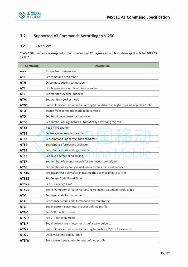
3.2. Supported AT Commands According to V.250
3.2.1. Overview
The V.250 commands correspond to the commands of AT Hayes-compatible modems applicable for 3GPP TS 27.007.
Command Description
+++ Escape from data mode
ATE Set command echo mode
ATH Disconnect existing connection
ATI Display product identification information
ATL Set monitor speaker loudness
ATM Set monitor speaker mode
ATN1 Some PC modem driver initial setting to handshake at highest speed larger than S37
ATO Switch from command mode to data mode
ATQ Set Result code presentation mode
ATS0 Set number of rings before automatically answering the call
ATS1 Read RING counter
ATS2 Set escape sequence character
ATS3 Set command line termination character
ATS4 Set response formatting character
ATS5 Set command line editing character
ATS6 Set pause before blind dialing
ATS7 Set number of seconds to wait for connection completion
ATS8 Set number of seconds to wait when comma dial modifier used
ATS10 Set disconnect delay after indicating the absence of data carrier
ATS12 Set Escape Code Guard Time
ATS25 Set DTR change Time
ATS95 Some PC modem driver initial setting to enable extended result codes
ATV Set result code format mode
ATX Set connect result code format and call monitoring
ATZ Set all current parameters to user defined profile
AT&C Set DCD function mode
AT&D Set DTR function mode
AT&F Set all current parameters to manufacturer defaults
AT&K Some PC modem driver initial setting to enable RTS/CTS flow control
AT&V Display current configuration
AT&W Store current parameter to user defined profile

M5311 AT Command Specification
16 /192
AT+DR V.42bis data compression reporting control
AT+DS V.42bis data compression control
AT+GCAP Request complete TA capabilities list
AT+GMI Request manufacturer identification
AT+GMM Request TA model identification
AT+GMR Request TA revision identification
AT+GOI Request global object identification
AT+GSN Request TA serial number identification (IMEI)
AT+ICF Set TE-TA control character framing
AT+IFC Set TE-TA local data flow control
AT+ILRR Set TE-TA local rate reporting mode
AT+IPR Set fixed local rate
ATD*99# Call control command
3.2.2. Detailed Description of Commands
3.2.2.1. +++
+++ Escape from data mode
Execute
command
+++
Response
The escape sequence is used to transfer from in-call data mode to in-call command mode without disconnecting from the remote modem. After a pause, responds with OK. Register S2 can be used to alter the escape character from ‘+’, the default, to any decimal value in the range 0 to 255.
Parameter None
Scope Channel Specific
Reference V.250 Note
This command is not preceded by AT and does not require a line terminator.
3.2.2.2. ATE
ATE Set command echo mode
Set command
ATE[<value>]
Response
• This setting determines whether the TA echoes characters received from TE during command state.
• OK
Parameter <value> 0 Echo mode off
1 Echo mode on
Scope Channel Specific

M5311 AT Command Specification
17 /192
Reference V.250 Note
3.2.2.3. ATH
ATH Disconnect existing connection
Execute
command
ATH[n]
Response
• Disconnect existing call by local TE from command line and terminate call
• OK, or, if there is an outstanding request for mobile-terminate PDP context activation and AT+CGAUTO is set accordingly, the request is rejected.
Note: OK is issued after circuit 109(DCD) is turned off, if it was previously on.
Parameter <n> 0 disconnect from line and terminate call
1 ask for outgoing call disconnection
Scope Channel Specific
Reference V.250,
27.007
Note
• Note that an outgoing data call can be aborted using any input character.
3.2.2.4. ATI
ATI Display product identification information
Execute
command
ATI
Response TA issues product information text
Example:
• CMCC
• M5311
• < Software_Version >
• < Hardware_Version >
• OK
Parameter None
Scope Channel Specific
Reference V.250 Note
3.2.2.5. ATL
ATL Set monitor speaker loudness
Set command ATL<value>

M5311 AT Command Specification
18 /192
Response
• No effect
• OK
Parameter
<value> 0 low speaker volume
1 low speaker volume
2 medium speaker volume
3 high speaker volume
Scope Generic
Reference V.250 Note
3.2.2.6. ATM
ATM Set monitor speaker mode
Set command
ATM<value>
Response
• No effect
• OK
Parameter
<value> 0 speaker is always off
1 speaker on until TA inform TE that carrier has been detected
2 speaker is always on when TA is off-hook
Scope Generic
Reference V.250 Note
3.2.2.7. ATN1
ATN1 Some PC modem driver initial setting to handshake at highest speed larger than S37
Set command
ATN1
Response
• Some standard PC modem drivers will send this AT command to initialize the setting, but it is meaningless in the 3GPP standard. Return OK and no effect for the setting.
• OK
Parameter None
Scope Generic
Reference V.250 Note
3.2.2.8. ATO
ATO Switch from command mode to data mode
Execute ATO[n]
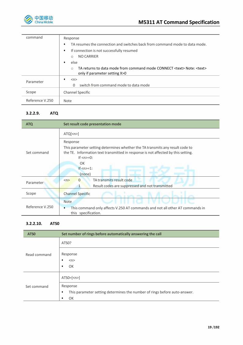
M5311 AT Command Specification
19 /192
command Response
• TA resumes the connection and switches back from command mode to data mode.
• If connection is not successfully resumed
o NO CARRIER
• else
o TA returns to data mode from command mode CONNECT <text> Note: <text> only if parameter setting X>0
Parameter • <n>
0 switch from command mode to data mode
Scope Channel Specific
Reference V.250 Note
3.2.2.9. ATQ
ATQ Set result code presentation mode
Set command
ATQ[<n>]
Response
This parameter setting determines whether the TA transmits any result code to the TE. Information text transmitted in response is not affected by this setting.
If <n>=0:
OK If <n>=1:
(none)
Parameter <n> 0 TA transmits result code
1 Result codes are suppressed and not transmitted
Scope Channel Specific
Reference V.250
Note
• This command only affects V.250 AT commands and not all other AT commands in this specification.
3.2.2.10. ATS0
ATS0 Set number of rings before automatically answering the call
Read command
ATS0?
Response
• <n>
• OK
Set command
ATS0=[<n>]
Response
• This parameter setting determines the number of rings before auto-answer.
• OK

M5311 AT Command Specification
20 /192
Parameter <n> 0 automatic answering is disabled
1-255 enable automatic answering on the ring number specified
Scope Channel Specific
Reference V.250 Note
3.2.2.11. ATS1
ATS1 Ring Counter
Read command
ATS1?
Response
• <n>
• OK
Set command
ATS1=[<n>]
Response
• This command will not alter the RING counter, but simply display:
• OK
Parameter <n> The number of “RING” strings sent to the TE as a result of receiving an incoming call.
0-255
Scope Channel Specific
Reference
Note
• If “RING” is not displayed on a particular channel due to other settings (such as suppression of all unsolicited events (ATQ)) then this value should not be incremented. This value is reset to 0 when receiving a new incoming call. Note that this command should also be made channel specific as with other ATS<x> commands.
Reference V.250 Note
3.2.2.12. ATS2
ATS2 Set escape sequence character
Read command
ATS2?
Response
• <n>
• OK
Set command
ATS2=[<n>]
Response
• This parameter setting determines the character recognized by the TA to indicate the escape sequence.
• OK

M5311 AT Command Specification
21 /192
Parameter <n> 0-43-255 escape sequence character Note: default 43 = ‘+’
Scope Channel Specific
Reference V.250 Note
3.2.2.13. ATS3
ATS3 Set command line termination character
Read command
ATS3?
Response
• <n>
• OK
Set command
ATS3=[<n>]
Response This parameter setting determines the character recognized by the TA to terminate an incoming command line. The TA also returns this character in output.
• OK
Parameter • <n> 0-13-127 command line termination character
o Note: default 13 = CR
Scope Channel Specific
Reference V.250 Note
3.2.2.14. ATS4
ATS4 Set response formatting character
Read command
ATS4?
Response
• <n>
• OK
Set command
ATS4=[<n>]
Response
• This parameter setting determines the character generated by the TA for result code and information text.
• OK
Parameter
• <n>
o 0-10-127 response formatting character
o Note: default 10 = LF
Scope Channel Specific
Reference V.250 Note

M5311 AT Command Specification
22 /192
3.2.2.15. ATS5
ATS5 Set command line editing character
Read command ATS5?
Response
• <n>
• OK
Set command ATS5=[<n>]
Response
• This parameter setting determines the character recognized by TA as a request to delete from the command line the immediately preceding character.
• OK
Parameter • <n>
o 0-8-127 command line editing character
o Note: default 8 = Backspace
Scope Channel Specific
Reference V.250 Note
3.2.2.16. ATS6
ATS6 Set pause before blind dialing
Read command
ATS6?
Response
• <n>
• OK
Set command
ATS6=[<n>]
Response
• No effect
• OK
Parameter • <n>
o 0-2-10 number of seconds to wait before blind dialing
Scope Channel Specific
Reference V.250 Note
3.2.2.17. ATS7
ATS7 Set number of seconds to wait for connection completion
Read command
ATS7?
Response
• <n>
• OK

M5311 AT Command Specification
23 /192
Set command
ATS7=[<n>]
Response
• This parameter setting determines the amount of time to wait for the connection completion in case of answering or originating a call.
• OK
Parameter • <n>
o 1-60-255 number of seconds to wait for connection completion
Scope Channel Specific
Reference V.250 Note
3.2.2.18. ATS8
ATS8 Set number of seconds to wait when comma dial modifier
Read command
ATS8?
Response
• <n>
• OK
Set command
ATS8=[<n>]
Response
• No effect
• OK
Parameter
• <n>
o 0 no pause when comma encountered in dial string
o 1-2-255 number of seconds to wait
Scope Channel Specific
Reference V.250 Note
3.2.2.19. ATS10
ATS10 Set disconnect delay after indicating the absence of data carrier
Read command
ATS10?
Response
• <n>
• OK
Set command
ATS10=[<n>]
Response
• This parameter setting determines the amount of time that the TA will remain connected in absence of data carrier. If the data carrier is once more detected before disconnect, the TA remains connected.
• OK
Parameter • <n>
o 1-15-254 number of tenths seconds of delay
Scope Channel Specific
Reference V.250 Note
• This command is not used, as there have been issues with in-band DCD

M5311 AT Command Specification
24 /192
dropping unexpectedly for CSD calls on some networks.
3.2.2.20. ATS12
This command sets the escape code guard time in fiftieths of a second. The escape guard time is used to measure when to detect the +++ escape sequence has been entered by the PC in order to drop out of data mode back to AT command mode.
The guard time determines the time that forms a guard period before and after three escape sequence characters. In order to distinguish an escape sequence from just three escape sequence characters in the data stream there is timing associated to the three escape sequence characters of an escape sequence.
The time between the last byte of the data stream and the first escape sequence character must be at least the guard time and the time between each escape sequence character of the escape sequence must be less than the guard time and no other byte is received after the third escape sequence character for the time of the guard time. If an escape sequence is detected, the OK result code will be sent to the DTE. Otherwise, the DCE will stay in data mode.
For example: “<Guard time>+++<Guard time>”
ATS12 Set Escape Code Guard Time
Read command
ATS12?
Response
• <n>
• OK
• NB: <n> is in 3 decimal digits format (e.g. Default value is given as 050).
If error is related to wrong AT syntax:
• +CME ERROR: <err>
Execution command
ATS12=<n>
Response
• OK
If error is related to wrong AT syntax:
• +CME ERROR: <err>
Parameters • <n> Numeric value of the escape guard time value in 1/50 seconds:
o 000-255 Number of 20 ms. Default is 050 (1 sec).
Scope Channel Specific
Reference 3GPP
TS 27.007
Note
• Set Escape Code Guard Time command
S12 Examples:
ATS12=100
OK
ATS12?
100
OK

M5311 AT Command Specification
25 /192
3.2.2.21. ATS25
This command sets the S-register 25 Detect DTR change time that contain the threshold for noticing a change in DTR. This time permits to the modem to ignore DTR before taking action specified by &Dn (See AT&D Circuit 108 behavior).
The value unit is in 1/100 seconds. Default value is set to 5 (50ms delay after a DTR drop before the modem acts on it).
ATS25 Set DTR change time
Read command
ATS25?
Response
• <n>
• OK
• <n> is in 3 decimal digits format (e.g. Default value is given as 000)
• If error is related to wrong AT syntax:
o +CME ERROR: <err>
Execution command
ATS25=<n>
Response
• OK
• If error is related to wrong AT syntax:
o +CME ERROR: <err>
Parameters • <n> Numeric value of DTR delay in 10 milliseconds:
o 000-255 Number of 10 ms. Default is 005.
Scope Channel Specific
Reference
3GPP TS
27.007
Note
• Set DTR change Time command
S25 Examples:
ATS25?
5
OK
ATS25=150
OK
ATS25?
150
OK
3.2.2.22. ATS95
ATS95 Some PC modem driver initial setting to enable extended result codes
Read command
ATS95?
Response
• OK

M5311 AT Command Specification
26 /192
Set command
ATS95=[<n>]
Response
• Some standard PC modem drivers will send this AT command to initialize the setting, but it is meaningless in the 3gpp standard. So we just return OK and no effect for the setting.
• OK
Parameter • <n> 0-255 meaningless for the GSM, and GPRS/Packet Domain setting
Scope N/A
Reference V.250 Note
3.2.2.23. ATV
ATV Set result code format mode
Set command
ATV[<value>]
Response
This parameter setting determines the contents of the header and trailer transmitted with result codes and information responses.
When <value>=0
0
When <value>=1
OK
Parameter
<value>
0 Information response: <text><CR><LF>
Short result code format: <numeric code><CR> 1 Information response: <CR><LF><text><CR><LF>
Long result code format: <CR><LF><verbose code><CR><LF>
Scope Channel Specific
Reference V.250 Note
3.2.2.24. ATX
ATX Set CONNECT result code format and call monitoring
Set command
ATX[<value>]
Response
• This parameter setting determines whether or not the TA detected the presence of dial tone and busy signal and whether or not TA transmits particular result codes
• OK

M5311 AT Command Specification
27 /192
Parameter
<value>
0 CONNECT result code only returned, dial tone and busy detection are both disabled
1 CONNECT<text> result code only returned, dial tone and busy detection are both disabled
2 CONNECT<text> result code returned, dial tone detection is enabled, busy detection is disabled
3 CONNECT<text> result code returned, dial tone detection is disabled, busy detection is enabled
4 CONNECT<text> result code returned, dial tone and busy detection are both enabled
Scope Channel Specific
Reference V.250 Note
3.2.2.25. ATZ
ATZ Set all current parameters to user defined profile
Execute command
ATZ[<value>]
Response
• TA sets all current parameters to the user defined profile.
o Note1: The user-defined profile is stored in non-volatile memory.
o Note2: If the user profile is not valid, it will default to the factory default profile.
o Note3: Any additional commands on the same command line are ignored.
• OK
Parameter <value>
0 Reset to profile number 0
Scope • Channel Specific and Generic: each parameter may be Channel Specific or Generic (see
command for individual parameter)
Reference V.250 Note
3.2.2.26. AT&C
AT&C Set circuit Data Carrier Detect (DCD) function mode
Set command
AT&C[<value>]
Response
• This parameter determines how the state of circuit 109(DCD) relates to the detection of received line signal from the distant end.
• OK
Parameter
<value>
0 DCD line is always ON
1 DCD line is ON only in the presence of data carrier
Scope Channel Specific
Reference V.250 Note

M5311 AT Command Specification
28 /192
3.2.2.27. AT&D
AT&D Set circuit Data Terminal Ready (DTR) function mode
Set command
AT&D[<value>]
Response
• This parameter determines how the TA responds when circuit 108/2(DTR) is changed from the ON to the OFF condition during data mode.
• OK
Parameter
<value>
0 TA ignores status on DTR
1 ON->OFF on DTR: Change to command mode with call remaining connected
2 ON->OFF on DTR: Disconnect call, change to command mode. During state DTR=OFF is auto-answer off.
Scope Channel Specific
Reference V.250 Note
3.2.2.28. AT&F
AT&F Set all current parameters to manufacturer defaults
Execute command
AT&F[value]
Response
• TA sets all current parameters to the manufacturer defined profile.
• OK
Parameter <value>
0 set all TA parameters to manufacturer defaults
Scope Channel Specific and Generic: each parameter may be Channel Specific or Generic (see
command for individual parameter)
Reference V.250 Note
3.2.2.29. AT&K
AT&K Flow control setting
Execute command
AT&K[<value>]
Response
• OK
Parameter
<value>
0 No flow control
3 RTS /CTS flow control (hardware)
4 XON/XOFF flow control (software)
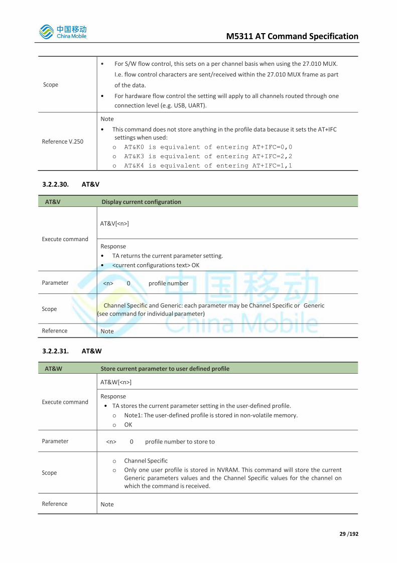
M5311 AT Command Specification
29 /192
Scope
• For S/W flow control, this sets on a per channel basis when using the 27.010 MUX.
I.e. flow control characters are sent/received within the 27.010 MUX frame as part
of the data.
• For hardware flow control the setting will apply to all channels routed through one
connection level (e.g. USB, UART).
Reference V.250
Note
• This command does not store anything in the profile data because it sets the AT+IFC settings when used:
o AT&K0 is equivalent of entering AT+IFC=0,0
o AT&K3 is equivalent of entering AT+IFC=2,2
o AT&K4 is equivalent of entering AT+IFC=1,1
3.2.2.30. AT&V
AT&V Display current configuration
Execute command
AT&V[<n>]
Response
• TA returns the current parameter setting.
• <current configurations text> OK
Parameter <n> 0 profile number
Scope Channel Specific and Generic: each parameter may be Channel Specific or Generic
(see command for individual parameter)
Reference Note
3.2.2.31. AT&W
AT&W Store current parameter to user defined profile
Execute command
AT&W[<n>]
Response
• TA stores the current parameter setting in the user-defined profile.
o Note1: The user-defined profile is stored in non-volatile memory.
o OK
Parameter <n> 0 profile number to store to
Scope
o Channel Specific
o Only one user profile is stored in NVRAM. This command will store the current Generic parameters values and the Channel Specific values for the channel on which the command is received.
Reference Note

M5311 AT Command Specification
30 /192
3.2.2.32. AT+DR
AT+DR V.42bis data compression reporting control
Test command
AT+DR=?
Response
• +DR:(list of supported <value>s) OK
Read command
AT+DR?
Response
• +DR: <value> OK
Set command
AT+DR=<value>
Response
• This parameter setting determines whether the intermediate result code of the current data compressing is reported by TA to TE after a connection establishment.
• OK
Unsolicited result
code
Intermediate result code
• +DR: <type>
Note: reported at call set up
Parameter
<value>
0 reporting disabled
1 reporting enabled
<type>
NONE data compression is not in use V42B Rec. V42bis is in use in both direction V42B RD Rec. V42bis is in use in receive direction only
V42B TD Rec. V42bis is in use in transmit direction only
Scope Channel Specific
Reference V.250 Note
3.2.2.33. AT+DS
AT+DS V.42bis data compression control
Test command
AT+DS=?
Response
• +DS:(list of supported <p0>s), (list of supported <n>s), (list of supported <p1>s), (list of supported <p2>s)
• OK
Read command
AT+DS?
Response
• +DS: <p0>,<n>,<p1>,<p2>
• OK

M5311 AT Command Specification
31 /192
Set command
AT+DS=[<p0>,[<n>,[<p1>,[<p2>]]]]
Response
• OK This parameter setting determines the possible data compression mode by TA at the compression negotiation with the remote TA after a call set up.
Note1: only for data call
Note2: GSM transmits the data transparent. The remote TA may support this compression.
Parameter
Note: see also ITU V.42bis
<p0>
0 NONE
1 transmit only
2 receive only
3 both direction, but allow negotiation
<n>
0 allow negotiation of p0 down
1 do not allow negotiation of p0 - disconnect on difference
<p1>
512-1024 dictionary size.(default determined by manufacturer)
<p2>
6-20-64 maximum string size (default 20)
Scope Channel Specific
Reference V.250 Note
3.2.2.34. AT+GCAP
AT+GCAP Request complete TA capabilities list
Execute command
AT+GCAP
Response
• TA reports a list of additional capabilities.
• +GCAP: <name>s
• OK
Parameter <name> example, +CGSM
Scope Channel specific (response output only on channel which entered the command)
Reference V.250 Note
3.2.2.35. AT+GMI
AT+GMI Request manufacturer identification
Execute command
AT+GMI
Response
• TA returns manufacturer identification text.
• <manufacturer> OK

M5311 AT Command Specification
32 /192
Parameters <manufacturer>
Scope Channel specific (response output only on channel which entered the command)
Reference V.250 Note
3.2.2.36. AT+GMM
AT+GMM Request TA model identification
Execute command
AT+GMM
Response
• TA returns product model identification text.
• <model>
• OK
Parameters <model>
Scope Channel specific (response output only on channel which entered the command)
Reference V.250 Note
3.2.2.37. AT+GMR
AT+GMR Request TA revision identification
Execute command
AT+GMR
Response
• TA reports one or more lines of information text that permit the user to identify the version, revision level or data or other information of the device.
• <Revision>
• OK
Scope Channel specific (response output only on channel which entered the command)
Reference V.250 Note
3.2.2.38. AT+GOI
AT+GOI Request global object identification
Execute command
AT+GOI
Response
• TA reports one or more lines of information text that permit the user to identify the device, based on the ISO system for registering unique object identifiers.
Parameter <Object Id> identifier of device type
o see X.208, 209 for the format of <Object Id>. This string is customer specific
Scope Channel specific (response output only on channel which entered the command)
Reference V.250 Note
M5311 AT Command Specification
33 /192
3.2.2.39. AT+GSN
AT+GSN Request TA serial number identification (IMEI)
Execute command
AT+GSN
Response
• TA reports the IMEI (International Mobile Equipment Identifier) number in information text that permits the user to identify the individual ME device.
• <sn>
• OK
Parameter <sn> IMEI of the telephone (International Mobile station Equipment Identity)
Scope Channel specific (response output only on channel which entered the command)
Reference V.250 Note
• The serial number (IMEI) is varied by individual ME device.
3.2.2.40. AT+ICF
AT+ICF Set TE-TA control character framing
Test command
AT+ICF=?
Response
• +ICF:(list of supported <format>s), (list of supported <parity>s)
• OK
Read command
AT+ICF?
Response
• +ICF: <format>,<parity> OK
o Note: This framing is applied for command state
Set command
AT+ICF=[<forma t>,[<parity>]]
Response
• This parameter setting determines the serial interface character framing format and parity received by TA from TE.
• Note: +IPR=0 forces +ICF=0
• OK

M5311 AT Command Specification
34 /192
Parameter
Note: The parity field is ignored if the format field specifies no parity.
<format>
1 8 data 0 parity 2 stop
2 8 data 1 parity 1 stop 3 8 data 0 parity 1 stop
4 7 data 0 parity 2 stop
5 7 data 1 parity 1 stop
6 7 data 0 parity 1 stop <parity>
0 odd
1 even
2 mark (1)
3 space (0)
Scope Channel Specific
Reference V.250 Note
• Not applicable to USB interface.
3.2.2.41. AT+IFC
AT+IFC Set TE-TA local data flow control
Test command
AT+IFC=?
Response
• +IFC:(list of supported <dce_by_dte>s), (list of supported <dte_by_dce>s) • OK
Read command
AT+IFC?
Response
• +IFC: <dce_by_dte>,<dte_by_dce>
• OK
Note: This flow control is applied for data mode
Set command
AT+IFC=[<dce_by_dte>[,<dte_by_dce>]]
Response
• This parameter setting determines the data flow control on the serial interface for data mode.
• OK
Parameter
<dce_by_dte> specifies the method will be used by TE at receive of data from TA
0 None
1 XON/XOFF, don’t pass characters on to data stack
2 line 133: Ready for Receiving
<dte_by_dce> specifies the method will be used by TA at receive of data from TE
0 None
1 XON/XOFF
2 line 106: Clear to send(CTS)
Scope Channel Specific

M5311 AT Command Specification
35 /192
Reference V.250
Note
• M5311 uses line 105 (RTS) for this method.
• For Software flow control, this sets on a per channel basis when using the 27.010 MUX. I.e. flow control characters are sent/received within the 27.010 MUX frame as part of the data.
• For hardware flow control the setting will apply to all channels routed through one connection level (e.g. USB, UART).
3.2.2.42. AT+ILRR
AT+ILRR Set TE-TA local rate reporting mode
Test command
AT+ILRR=?
Response
• +ILRR:(list of supported <value>s OK
Read command
AT+ILRR?
Response
• +ILRR: <value> OK
Set command
AT+ILRR=<value>
Response
• This parameter setting determines whether an intermediate result code of local rate is reported at connection establishment. The rate is applied after the result code of the connection is transmitted to TE.
• OK
Unsolicited result
code
• +ILLR:<rate>
Note: It indicates port rate settings on connection.
Parameter
<value>
0 Disables reporting of local port rate
1 Enables reporting of local port rate
<rate> port rate setting on call connection in Baud per second
9600
19200
38400
57600
115200
230400
460800
Scope • Scope
o Channel Specific
Reference V.250 Note

M5311 AT Command Specification
36 /192
3.2.2.43. AT+IPR
AT+IPR Set fixed local rate
Test command
AT+IPR=?
Response
• +IPR: (list of supported auto detectable <rate>s),(list of supported fixed-only<rate>s)
• OK
Read command
AT+IPR?
Response
• +IPR: <rate>
• OK
Set command
AT+IPR=<rate>
Response
• This parameter setting determines the data rate of the TA on the serial interface. The rate of command takes effect following the issuance of any result code associated with the current command line.
• OK
Parameter
<rate> Baud-rate per second
0(auto baud rate)
110
300
1200
2400
4800
9600
19200
38400
57600
115200
230400
460800
921600
Scope Channel Specific
Reference V.250
Note
• The setting will apply to all channels routed through one connection level for UART.
• Not applicable for USB interface.
• AT+IPR=0, auto baud rate takes effect following these three cases: 1. Commands AT+IPR=0 returns ‘OK’. 2.wake up from sleep. 3. Software/Hardware reboot. Only one of these three cases can trigger an adaptive baud rate.
3.2.2.44. ATD*99#
This command is used by the PC to make a packet domain connection using the standard AT dial command.
Note that is it is possible for ATD*99# to re-use an already active context as long as the context was activated

M5311 AT Command Specification
37 /192
with no data connection on the same channel (i.e. activated with AT+CGACT).
ATD Request Packet Domain Service
Execute command
ATD*<GPRS_SC>[*[<called_address>] [*[<L2P>][*[<cid>[,<cid>[,…]]]]]]#
Response • UE attempts to set up a mobile originated PDP context. Note: This command may be aborted generally by receiving a character during execution. The aborting is not possible during some states of PDP context activation.
o If no dial tone and (parameter setting X=2 or X=4)
NO DIALTONE o If busy and (parameter setting X=3 or X=4)
BUSY o If a PDP context cannot be established
NO CARRIER o If connection successful
CONNECT UE switches to packet switched data state.
o When UE returns to command mode after PDP MO context deactivation OK
Parameter
<GPRS_SC> GPRS Service code. Digit string value 99 identifies a request to use PSD.
<called_address> String identifying called party in address space applicable to PDP.
This parameter is not supported.
<L2P> Layer 2 protocol to be used.
90001: Raw TCP/IP (No L2P required). Note that username and password must be set for the <cid> using the appropriate proprietary AT command (AT+CGAUTH).
<cid> Digit string specifying a particular PDP context
definition (see AT+GCDCONT, AT+GCDSCONT).
Scope Channel Specific

M5311 AT Command Specification
38 /192
Reference 3GPP TS 27.007
Note
<L2P> value 90001 is used only for communication to a peer which supports raw TCP/IP routing to the modem and the additional AT commands required to support setup of IP configuration information. Note that if the <cid> value is omitted (i.e. just ATD*99# is entered) then the following takes place:
• If the entity has a defined cid or a cid is defined but has an invalid entity, we will use that cid if the cid is not provided
• If the above condition is not met, we will use the next free cid
• In addition, we also check the cid is not reserved for a Mobile Terminated (MT) PDP context (by using AT*MMTPDPCID command). If it is reserved, we will skip it and continue to find a cid according to the rules above
• When a Mobile Terminated PDP context is incoming, we firstly check whether a cid has
been reserved for MT PDP or not (using the AT*MMTPDPCID command). If not, we will
get a free cid according to the rules above Note that it is better to enter the <cid> value as the behavior of the dialup will be more predictable. When a new cid is used, the PDP context information associated with the cid (APN, etc) is copied from the default PDP context information stored in the background layer using AT command AT*MCGDEFCONT.
M5311 AT Command Specification
39 /192
3.3. Supported AT Commands According to 3GPP TS 27.007
3.3.1. Overview
The 3GPP TS 27.007 commands are for remote control of NB-IoT functionality.
Command Description
AT+CCLK Clock
AT+CEER Extended error report
AT+CFUN Set phone functionality
AT+CGACT Context activation
AT+CGATT GPRS/Packet Domain attach or detach
AT+CGDATA Enter Data State
AT+CGDCONT Define PDP context
AT+CGMI Request manufacturer identification
AT+CGMM Request model identification
AT+CGMR Request revision identification
AT+CGOI Request global object identification
AT+CGPADDR Show PDP address
AT+CGREG Network registration status
AT+CEREG EPS network registration status
AT+CGCONTRDP PDP context read dynamic parameters
AT+CGSN Request product serial number identification (identical with +GSN)
AT+CIMI Request international mobile subscriber identity
AT+CLCK Facility lock
AT+CMAR Master Reset
AT+CMEE Report mobile equipment error
AT+CMUX 3GPP TS 27.010 Multiplexer control
AT+COPN Read operator names
AT+COPS Operator selection
AT+CESQ Extended signal quality
AT+CSQ Signal Quality
AT+CPIN Enter pin
AT+CPOL Preferred operator list
AT+CPWD Change password
AT+CR Service reporting control
AT+CREG Network registration
AT+CSIM Generic SIM Access
AT+CRSM Restricted SIM access
AT+CSCS Select TE character set

M5311 AT Command Specification
40 /192
AT+CTZR Time Zone Reporting
AT+CTZU Automatic Time Zone Update
AT+CPLS Selection of preferred PLMN List
AT+CPSMS Power saving mode selection
AT+CIPCA Enable/disable activation of PDN connection on attach.
AT+CCIOTOPT CIoT optimization configuration
AT+CEDRXS eDRX setting
AT+CEDRXRDP eDRX read dynamic parameters
AT+CGAPNRC Report APN uplink rate control information
AT+CSCON Query and generate URC for signaling connection station (CONNECTED or IDLE)
AT+CCHO Open UICC Logical Channel
AT+CCHC Close UICC Logical Channel
AT+CGLA Generic UICC Logical Channel Access
AT+CRLA Restricted UICC Logical Channel Access
AT+CPINR Remaining PIN Retries
AT+CGPIAF Printing IP Address Format
AT+CGEREP Packet Domain Event Reporting
AT+CGDEL Delete non-active PDP Context(s)
AT+CGAUTH Define PDP Context Authentication Parameters
3.3.2. Detailed Descriptions of Commands
3.3.2.1. AT+CCLK
AT+CCLK Clock
Read command
AT+CCLK?
Response
• +CCLK: <time>
• OK
• +CME ERROR: <err>
Set command
AT+CCLK=<time>
Response
• OK
• +CME ERROR: <err>

M5311 AT Command Specification
41 /192
Parameters
<time> string type value;
format is " yy/MM/dd,hh:mm:sszz”; where characters indicate year
(two last digits), month, day, hour, minutes and seconds and time zone
(indicates the difference, expressed in quarters of an hour, between the
local time and GMT; range -47...+48). E.g. 6th of May 1994, 22:10:00 GMT+2
hours equals to "94/05/06,22:10:00+08"
Note: If MT does not support time zone information then the three last characters of <time> are not returned by +CCLK?.
Scope o Channel specific for read command
o Generic for set command
Reference 3GPP TS
27.007 Note
3.3.2.2. AT+CEER
AT+CEER Extended error report
Execute command
AT+CEER
Response
• TA returns an extended report of the reason for the last call release.
• +CEER: <report>
• OK
Scope Channel Specific
Reference 3GPP TS
27.007
Note
• Note that the cause display mode is set using the AT command AT*MCEERMODE. The response can be in either textual format (default) or numeric (according to 3GPP cause values). For more details see the AT*MCEERMODE command description.
3.3.2.3. AT+CFUN
AT+CFUN Set phone functionality
Test command
AT+CFUN=?
Response
• +CFUN: (list of supported <fun>s), (list of supported <rst>s)
• OK
• +CME ERROR: <err>
Read command
AT+CFUN?
Response
• +CFUN: <fun>
• OK
• +CME ERROR: <err>

M5311 AT Command Specification
42 /192
Set command
AT+CFUN=<fun>[,<rst>]
Response
• OK
• +CME ERROR: <err>
Parameters
<fun>
0 minimum functionality
1 full functionality (Default)
4 disable phone both transmit and receive RF circuits
7 disable phone SIM only. Transmit and receive circuits still active 5,6,8…127 reserved for manufacturers as intermediate states between full and
minimum functionality
<rst>
0 do not reset the MT before setting it to <fun> power levelOnly set to <fun>
power level after MT has been reset, and for all subsequent resets.Do not
reset MT before setting it to <fun> power level and save <fun> value in NVRAM
for all subsequent resets.
Scope
o Channel Specific for test and read command
o Generic for set command
Reference 3GPP TS
27.007
Note
Settings 2 and 3 of <fun> are not supported.
• <fun> = 0 performs all system shutdown actions without removing power. It will take some time to return ok or error, during this time, other At Command input will not responded. The response time does not exceed 90s.
• <fun> = 1 performs a system startup
• <rst> = 0 shall always be the default if the <rst> parameter is not given.
Note that <rst> of 1 and 2 does not reset the modem as described in the 27.007 specification. They simply set a value in NVRAM so that <fun> value is activated on all subsequent modem resets.
3.3.2.4. AT+CGACT
The execution command is used to activate or deactivate the specified PDP context (s). After the command has completed, the UE remains in V.250 command state. If any PDP context is already in the requested state, the state for that context remains unchanged.
If the UE is not PS attached when the activation form of the command is executed, the UE first performs a PS attach and them attempts to activate the specified contexts.
Note that in the 27.007 specification there is the following statement:
For EPS, if an attempt is made to disconnect the last PDN connection, then the UE responds with ERROR
or, if extended error responses are enabled, a +CME ERROR.
This applies when use of CID0 is enabled for the PDN connection activated during attach. In fact, entering AT+CGACT=<0 or 1>,0 will generate ERROR response.
If CID0 mode is not enabled then it is possible to enter the AT+CGACT command to deactivate the last PDN connection from the point of view of the middleware. When the user uses AT+CGACT to disconnect the last PDN connection the following occurs:
The PDN connection is preserved in the protocol stack

M5311 AT Command Specification
43 /192
The PDN connection is disconnected at the middleware, so the <cid> for the PDN connection is marked as deactivated
OK response is returned rather than ERROR
For EPS, the activation request for an EPS bearer resource will be answered by the network by either an EPS dedicated bearer activation or EPS bearer modification request. The request must be accepted by the UE before the PDP context can be set in to established state.
If no <cid>s are specified the activation form of the command activates all defined contexts.
If no <cid>s are specified the deactivation form of the command deactivates all active contexts.
The read command returns the current activation states for all the defined PDP contexts. The test command is used for requesting information on the supported PDP context activation states.
AT+CGACT PDP Context activate or deactivate
Test command
AT+CGACT=?
Response
• +CGACT: (list of supported <state>s)
• OK
Read command
AT+CGACT?
Response
• +CGACT:<cid>,<state>[<CR><LF>+CGACT: <cid>,<state>[…]]
• OK
Set command
AT+CGACT=[<state>[,<cid> [,<cid>[,…]]]]
Response
• OK
• NO CARRIER
• ERROR
Parameter
<state> indicates the state of PDP context activation
0 deactivated
1 activated
Other reserved and will result in an ERROR response to the execution
command.
<cid> a numeric parameter which specifies a particular PDP context definition
(see +CGDCONT command)
Scope o Channel Specific for test and read command
o Generic for set command
Reference 3GPP TS
27.007
Note
• If context is deactivated successfully, NO CARRIER is returned
• If CID0 for PDN activated during attach is enabled, then AT+CGACT=<0 or 1>,0 will cause ERROR response.

M5311 AT Command Specification
44 /192
3.3.2.5. AT+CGATT
AT+CGATT GPRS/Packet Domain attach or detach
Test command
AT+CGATT=?
Response
• +CGATT: (list of supported <state>s)
• OK
Read command
AT+CGATT?
Response
• +CGATT: <state>
• OK
Set command
AT+CGATT=[<state>]
Response
• OK
• ERROR
Parameter
<state> indicates the state of GPRS/Packet Domain attachment
0 detached
1 attached
Other reserved and will result in an ERROR response to the execution
command.
Scope o Channel Specific for test and read command
o Generic for set command
Reference 3GPP TS
27.007
• <state>= 0 performs GPRS/Packet Domain detach actions. It will take some time to return ok or error, during this time, other At Command input will not responded. The response time does not exceed 90s.
3.3.2.6. AT+CGDATA
This command is used activate a PDP context / EPS bearer rather than using the ATD*99# method. It will be used by the Packet Transport mechanism for activating a PDP context / EPS bearer.
Note that is it is possible for AT+CGDATA to re-use an already active context as long as the context was activated with no data connection on the same channel (i.e. activated with AT+CGACT).
AT+CGDATA Enter Data State
Test command
AT+CGDATA=?
Response
• +CGDATA: (list of supported <L2P>s)
• OK
Set command AT+CGDATA=[<L2P>[,<cid>[,<cid>[,…]]]]

M5311 AT Command Specification
45 /192
Response
• OK
• ERROR
Parameter
• <L2P> a string parameter that indicates the layer 2 protocol to be used between the TE and MT:
o M-PT – Packet Transport Mechanism protocol for a PDP such as IP
o Other values are not supported and will result in an ERROR response to the execution command.
• <cid> a numeric parameter which specifies a particular PDP context definition (see +CGDCONT command)
Scope Channel Specific
Reference 3GPP TS
27.007
Note
• The command will enter data state once the PDP context has been activated<L2P> value M-PT represents no <l2p> but raw IP packet transfer.
• +++ escape from data mode.
3.3.2.7. AT+CGDCONT
The set command specifies PDP context parameter values for a PDP context identified by the (local) context identification parameter, <cid>. The number of PDP contexts that may be in a defined state at the same time is given by the range returned by the test command.
For EPS the PDN connection and its associated EPS default bearer is identified herewith. For EPS the <PDP_addr> shall be omitted.
A special form of the set command, +CGDCONT= <cid> causes the values for context number <cid> to become undefined.
The read command returns the current settings for each defined context.
The test command returns values supported as a compound value. If the UE supports several PDP types, <PDP_type>, the parameter value ranges for each <PDP_type> are returned on a separate line.
The feature "initial PDP context" may be supported and is a manufacturer specific option. For this option, the context with <cid>=0 (context number 0) is defined upon startup and does not need to be created with the +CGDCONT command. The initial PDP context has particular manufacturer specific default settings disassociated with any other default settings of +CGDCONT. When in E-UTRAN, the initial PDP context is automatically activated by the MT following a successful registration to the network depending on the setting of AT+CIPCA command. If all active contexts are deactivated, the initial PDP context can be (re)established. This is manufacturer specific and depends on the current RAT as well as how the active contexts are deactivated.
AT+CGDCONT Define the PDP context
Test command
AT+CGDCONT=?
Response
+CGDCONT: (range of supported <cid>s),<PDP_type>,,,(list of supported <d_comp>s),(list of supported <h_comp>s),(list of supported <IPv4AddrAlloc>s),(list of supported <request_type>s),(list of supported <P-CSCF_discovery>s),(list of supported <IM_CN_Signalling_Flag_Ind>s) ,(list of supported <NSLPI>s),(list of supported <securePCO>s),(list of supported <IPv4_MTU_discovery>s),(list of supported

M5311 AT Command Specification
46 /192
<Local_Addr_Ind>s),(list of supported<Non-IPMTUdiscovery>s)
[<CR><LF>+CGDCONT: (range of supported <cid>s),<PDP_type>,,,(list of supported <d_comp>s),(list of supported <h_comp>s),(list of supported<IPv4AddrAlloc>s),(list of supported <request_type>s),(list of supported <P-CSCF_discovery>s),(list of supported <IM_CN_Signalling_Flag_Ind>s), (list of supported <NSLPI>s),(list of supported <securePCO>s,(list of supported <IPv4_MTU_discovery>s),(list of supported <Local_Addr_Ind>s),,(list of supported <Non-IP_MTU_discovery>s)[...]]
Read command
AT+CGDCONT?
Response
[+CGDCONT:<cid>,<PDP_type>,<APN>,<PDP_addr>,<d_comp>,<h_comp>[,<IPv4AddrAlloc>[,<request_type>[,<P-CSCF_discovery>[,<IM_CN_Signalling_Flag_Ind>[,<NSLPI>[, <securePCO>[,<IPv4_MTU_discovery>[,<Local_Addr_Ind>[,<Non-IP_MTU_discovery>]]]]]]]]]]
[<CR><LF>+CGDCONT: <cid>,<PDP_type>,<APN>,<PDP_addr>,<d_comp>,<h_comp>[,<IPv4AddrAlloc>[,<request_type>[,<P-CSCF_discovery>[,<IM_CN_Signalling_Flag_Ind>[,<NSLPI>[,<securePCO>[, <IPv4_MTU_discovery>[,<Local_Addr_Ind>[,<Non- IP_MTU_discovery>]]]]]]]]]
[...]]
Set command
AT+CGDCONT=[<cid>,[<PDP_type>,[<APN>,[<PDP_addr>,[<d_comp>,[<h_comp>[,<IPv4AddrAlloc>[,<request_type>[,<P-CSCF_discovery>[,<IM_CN_Signalling_Flag_Ind>[,<NSLPI>[,<securePCO>
[,<IPv4_MTU_discovery>[,<Local_Addr_Ind>[,<Non-IP_MTU_discovery>]]]]]]]]]]]]]]]]
Response
• OK
• ERROR
Parameter
<cid> (PDP Context Identifier) a numeric parameter that specifies a particular PDP context definition.
o The parameter is local to the UE-TE interface and is used in other PDP context-related commands.
o The range of permitted values (minimum value = 1 or if the initial PDP context is supported minimum value = 0) is returned by the test form of the command.
• <PDP_type> (Packet Data Protocol type) a string parameter which specifies the type of packet data protocol :
o IP Internet Protocol (IETF STD 5)
o IPV6 Internet Protocol, version 6 (IETF RFC 2460)
o IPV4V6 Virtual <PDP_type>) introduced to handle dual IP stack UE capability (see 3GPP Technical Specifications 24.301).
o Non-IP Transfer of Non-IP data to external packet data Network (see 3GPP Technical Specifications 24.301).
• <APN> (Access Point Name) a string parameter, a logical name to select the GGSN or the external packet data network. If the value is null or omitted, then the subscription value will be requested.
• <PDP_addr> a string parameter that identifies the UE in the address space applicable to the PDP. If the value is null or omitted, then a value may be provided by the TE during the PDP startup procedure or, failing that, a dynamic address will be requested. The read form of the command will continue to return the null string even if an address has been allocated during the PDP startup procedure. The allocated address may be read using the +CGPADDR command.
o NOTE: For EPS, this field is omitted.
• <d_comp>: a numeric parameter that controls PDP data compression (applicable for SNDCP only) (refer 3GPP TS 04.65)

M5311 AT Command Specification
47 /192
o 0 - off (default if value is omitted)
o 1 - on (manufacturer preferred compression)
o 2 – V.42bis
o Other values are reserved.
• <h_comp>: a numeric parameter that controls PDP header compression (refer 3GPP TS 04.65)
o 0 – off (default if value is omitted)
o 1 – on (manufacturer preferred compression)
o 2 – RFC1144 (applicable for SNDCP only)
o 3 – RFC 2507
o 4 – RFC 3095 (ROHC) (applicable for PDCP only)
o Other values are reserved.
• <IPv4_MTU_discovery>: integer type; influences how the MT/TA requests to get the IPv4 MTU size, see 3GPP TS 24.008 sub-clause 10.5.6.3.
o 0 Preference of IPv4 MTU size discovery not influenced by +CGDCONT
o 1 Preference of IPv4 MTU size discovery through NAS signaling
• <Non-IP_MTU_discovery>: integer type; influences how the MT/TA requests to get the
Non-IP MTU size, see 3GPP TS 24.008 sub-clause 10.5.6.3.
o 0 Preference of Non-IP MTU size discovery not influenced by +CGDCONT
o 1 Preference of Non-IP MTU size discovery through NAS signaling supported
Scope o Channel Specific for test and read command
o Generic for set command
Reference 3GPP
TS 27.007
• Note
o If the initial PDP context is supported, the context with <cid>=0 is automatically defined at startup. As all other contexts, the parameters for <cid>=0 can be modified with +CGDCONT. If the initial PDP context is supported, +CGDCONT=0 resets context number 0 to its particular default settings.
o Parameters: <IPv4AddrAlloc>,<request_type>,<P-CSCF_discovery>,<IM_CN_Signalling_Flag_Ind>,<NSLPI>,<securePCO>,<Local_Addr_Ind>, <IPv4_MTU_discovery> and <Non-IP_MTU_discovery> are not supported in M5311 modem.
3.3.2.8. AT+CGMI
AT+CGMI Request manufacturer identification
Execute command
AT+CGMI
Response
• TA returns manufacturer identification text.
• <manufacturer>
• OK
Parameters • <manufacturer>
Scope Channel Specific
Reference 3GPP TS
27.007 Note
3.3.2.9. AT+CGMM

M5311 AT Command Specification
48 /192
AT+CGMM Request model identification
Execute command
AT+CGMM
Response
• TA returns product model identification text
• <model>
• OK Parameters <model>
Scope Channel Specific
Reference 3GPP TS
27.007 Note
3.3.2.10. AT+CGMR
AT+CGMR Request revision identification
Execute command
AT+CGMR
Response
• TA returns product software version identification text
• <revision>
• OK
Parameters <revision>
Scope Channel Specific
Reference 3GPP TS
27.007 Note
3.3.2.11. AT+CGOI
AT+CGOI Request global object identification
Execute command
AT+CGOI
Response
• OK
• TA reports one or more lines of information text that permit the user to identify the device, based on the ISO system for registering unique object identifiers.
Parameter <Object Id> identifier of device type
o See X.208, 209 for the format of <Object Id>. This string is customer specific.
Scope Channel Specific
Reference V.250/
3GPP TS 27.007 Note
3.3.2.12. AT+CGPADDR
AT+CGPADDR Show PDP address

M5311 AT Command Specification
49 /192
Test command
AT+CGPADDR=?
Response
• +CGPADDR: (list of defined <cid>s)
• OK
Set command
AT+CGPADDR=[<cid>[,<cid>[,…]]]
Response
• +CGPADDR: <cid>,<PDP_addr>[<CR><LF>+CGPADDR: <cid>,<PDP_addr>[...]]
• OK
Parameter
• <cid> a numeric parameter which specifies a particular PDP context definition (see +CGDCONT command). If no <cid> is specified, the addresses for all defined contexts are returned.
• <PDP_addr> a string that identifies the MT in the address space applicable to the PDP. The address may be static or dynamic. o For a static address, it will be the one set by the +CGDCONT command when the
context was defined.
o For a dynamic address, it will be the one assigned during the last PDP context activation that used the context definition referred to by <cid>. <PDP_address> is omitted if none is available.
Scope Channel specific for test command
Reference 3GPP TS
27.007
Note
• This command dictates the behavior of PPP in the ME but not that of any other GPRS/Packet Domain-enabled foreground layer, e.g. browser.
3.3.2.13. AT+CGREG
This command is used to display the packet switched network registration status.
AT+CGREG Network registration status
Test command
AT+CGREG=?
Response
• +CGREG: (list of supported <n>s)
• OK
Read command
AT+CGREG?
Response
• +CGREG: <n>,<stat>[,<lac>,<ci>[,<AcT>]]
• +CME ERROR: <err>
• OK
Set command
AT+CGREG=[<n>]
Response
• OK

M5311 AT Command Specification
50 /192
Parameter
<n>
0 disable network registration unsolicited result code
1 enable network registration unsolicited result code +CGREG: <stat>
2 enable network registration and location information unsolicited result code +CGREG: <stat>[,<lac>,<ci>[,<AcT>,<rac>]]
<stat>
0 not registered, ME is not currently searching a new operator to register to
1 registered, home network
2 not registered, but ME is currently searching for a new operator to
register to
3 registration denied
4 unknown
5 registered, roaming
6 registered for “SMS only”, home network (applicable only when <Act> indicates E-UTRAN
7 registered for “SMS only”, roaming (applicable only when <Act> indicates E-UTRAN
<lac> string type; two byte location area code in
hexadecimal format (e.g. "00C3" equals 195 in decimal)
<ci> string type; four byte UTRAN/GERAN/E-UTRAN cell ID in hexadecimal format
<AcT> access technology of the registered network
9 NB-IoT
<rac> string type; one byte routing area code in hexadecimal format
Scope Channel Specific
Reference 3GPP TS
27.007
Note
• The set command controls the presentation of an unsolicited result code +CGREG: <stat> when <n>=1 and there is a change in the UE's GPRS network registration status, or code +CGREG: <stat>[,<lac>,<ci>[,<AcT>,<rac>]] when <n>=2 and there is a change of the network cell.
• For NB-IoT product, only <AcT> value of 9 is valid.
3.3.2.14. AT+CEREG
The set command controls the presentation of an unsolicited result code +CEREG: <stat> when <n>=1 and
there is a change in the UE's EPS network registration status, or result code +CEREG:
<stat>[,<tac>,<ci>[,<AcT>]] when <n>=2 and there is a change of the network cell.
NOTE: If the EPS UE also supports circuit mode services and/or GPRS services, the +CREG command and +CREG: result codes and/or the +CGREG command and +CGREG: result codes apply to the registration status and location information for those services.
The read command returns the status of result code presentation and an integer <stat> that shows whether the
network has currently indicated the registration of the UE. Location information elements <tac>, <ci> and
<AcT> are returned only when <n>=2 and UE is registered in the network.
AT+CEREG EPS Network Registration Status
Test Command AT+CEREG=?

M5311 AT Command Specification
51 /192
Response
• +CEREG: (list of supported <n>s)
• OK
Read command
AT+CEREG?
Response
• when <n>=0, 1, 2 or 3 and command successful:
o +CEREG: <n>,<stat>[,[<tac>],[<ci>],[<AcT>[,<cause_type>,<reject_cause>]]]
• when <n>=4 or 5 and command successful:
o +CEREG: <n>,<stat>[,[<lac>],[<ci>],[<AcT>],[<rac>][,[<cause_type>],[<reject_cause>][, [<Active-Time>],[<Periodic-TAU>]]]]
• If error is related to wrong AT syntax or operation not allowed:
o +CME ERROR: <err>
Execution
command
AT+CEREG=[<n>]
Response
• OK
• If error is related to wrong AT syntax:
o +CME ERROR: <err>
Unsolicited result
code See Parameters below
Parameters
<n>
0 disable network registration unsolicited result code
1 enable network registration unsolicited result code +CEREG: <stat>
2 enable network registration and location information unsolicited result code +CEREG: <stat>[,<[lac>,]<[ci>],[<AcT>],[<rac>]]
3 enable network registration, location information and EMM cause value information unsolicited result code +CEREG:
<stat>[,[<lac>],[<ci>],[<AcT>],[<rac>][,<cause_type>,<reject_cause>]]
4 For a UE that wants to apply PSM, enable network registration and location information unsolicited result code +CEREG: <stat>[,[<lac>],[<ci>],[<AcT>],[<rac>][,,[,[<Active-Time>], [<Periodic-RAU>],[<GPRS-READY-timer>]]]]
5 For a UE that wants to apply PSM, enable network registration, location information and EMM cause value information unsolicited result code +CEREG: <stat>[,[<lac>],[<ci>],[<AcT>],[<rac>][,[<cause_type>], [<reject_cause>][,[<Active-Time>],[<Periodic-RAU>], [<GPRS-READY-timer>]]]]
<stat> EPS registration status
0 not registered, ME is not currently searching a new operator to register to
1 registered, home network
2 not registered, but ME is currently searching for a new operator
to register to
3 registration denied
4 unknown
5 registered, roaming
6 registered for “SMS only”, home network (applicable only when
<Act> indicates NB-IOT
7 registered for “SMS only”, roaming (applicable only when
M5311 AT Command Specification
52 /192
<Act> indicates NB-IOT <tac> string type; two byte tracking area code in
hexadecimal format (e.g. "00C3" equals 195 in decimal).
<ci> string type; four byte GERAN/UTRAN/E-UTRAN cell ID in hexadecimal format <AcT> access technology of the registered network
9 NB-IoT
<cause_type> integer type; indicates the type of <reject_cause>
0 Indicates that <reject_cause> contains an EMM cause value, see 3GPP TS 24.301 Annex A.
1 Indicates that <reject_cause> contains a manufacturer-specific cause.
<reject_cause> integer type; contains the cause of the failed registration. The value is of type as defined by <cause_type>. <Active-Time> string type; one byte in an 8-bit format. Indicates the Active Time value (T3324) allocated to the UE in E-UTRAN. The Active Time value is coded as one byte (octet 3) of the GPRS Timer 2 information element coded as bit format (e.g. "00100100" equals 4 minutes). For the coding and the value range, see the GPRS Timer 2 IE in 3GPP TS 24.008 Table 10.5.163/3GPP TS 24.008. See also 3GPP TS 23.682 and 3GPP TS 23.401. <Periodic-TAU> string type; one byte in an 8-bit format. Indicates the extended periodic TAU value (T3412) allocated to the UE in E-UTRAN. The extended periodic TAU value is coded as one byte (octet 3) of the GPRS Timer 3 information element coded as bit format (e.g. "01000111" equals 70 hours). For the coding and the value range, see the GPRS Timer 3 IE in 3GPP TS 24.008, Table 10.5.163a/3GPP TS 24.008. See also 3GPP TS 23.682 and 3GPP TS 23.401.
Scope Channel Specific
Reference Note
• For NB-IoT product, only <AcT> value of 9 is valid.
3.3.2.15. AT+CGCONTRDP
The execution command returns the relevant information for a primary PDP Context established by the network with the primary context identifier <cid>. If the context cannot be found an ERROR response is returned.
If the UE has dual stack capabilities, two lines of information are returned per <cid>. First one line with the IPv4 parameters followed by one line with the IPv6 parameters. If the parameter <cid> is omitted, the relevant information for all established PDP contexts are returned. NOTE: The dynamic part of the PDP context will only exist if established by the network.
The test command returns a list of <cid>s associated with active contexts.
AT+CGCONTRDP PDP Context Read Dynamic Parameters
Test Command
AT+CGCONTRDP=?
Response
• +CGCONTRDP: (list of <cid>s associated with active contexts)
• OK
Read command
AT+CGCONTRDP?
Response
• +CME ERROR: <err>

M5311 AT Command Specification
53 /192
Execution
command
AT+CGCONTRDP=[<cid>]
Response +CGCONTRDP: <cid>, <bearer_id>, <apn>[, <local address and subnet mask>[, <gw_addr>[, <DNS_prim_addr>[, <DNS_sec_addr>[,<P-CSCF_prim_addr>[,<P-CSCF_sec_addr>[,<IM_CN_Signalling_Flag>[, <LIPA_indication>[,<IPv4_MTU>[,<WLAN_Offload>[,<Local_Addr_Ind>[,<Non-IP_MTU>[,<Serving_PLMN_rate_control_value>]]]]]]]]]]]]] [<CR><LF> +CGCONTRDP: <cid>,<bearer_id>,<apn>[,<local address and subnet mask>[,<gw_addr>[,<DNS_prim_addr>[,<DNS_sec_addr>[,<P-CSCF_prim_addr>[,<P-CSCF_sec_addr>[,<IM_CN_Signalling_Flag>[, <LIPA_indication>[,<IPv4_MTU>[,<WLAN_Offload>[,<Local_Addr_Ind>[,<Non-IP_MTU>[,<Serving_PLMN_rate_control_value>]]]]]]]]]]]]][…]]
OK
If error is related to wrong AT syntax:
+CME ERROR: <err>
Parameters
<cid> a numeric parameter which specifies a particular primary PDP
context definition. The parameter is local to the TE-UE interface and is
used in other PDP context-related commands.
<bearer_id> a numeric parameter which identifies the bearer, EPS Bearer in EPS
and NSAPI in UMTS/GPRS.
<APN> a string parameter which is a logical name that was used to select the
GGSN or the external packet data network.
<local address and subnet mask>
a string parameter which shows the IP Address and subnet mask of
the UE. The string is given as dot-separated numeric (0-255)
parameters on the form:
"a1.a2.a3.a4.m1.m2.m3.m4" for IPv4 or
"a1.a2.a3.a4.a5.a6.a7.a8.a9.a10.a11.a12.a13.a14.a15.a16.m1.m2.m3.
m4.m5.m6.m7.m8.m9.m10.m11.m12.m13.m14.m15.m16", for IPv6. <gw_addr> a string parameter which shows the Gateway Address of the UE. The
string is given as dot-separated numeric (0-255) parameters.
<DNS_prim_addr> a string parameter which shows the IP Address of the primary DNS Server.
<DNS_sec_addr> a string parameter which shows the IP address of the secondary DNS Server.
<IPv4_MTU> integer type; shows the IPv4 MTU size in octets.
<Non-IP_MTU> integer type; shows the Non-IP MTU size in octets.
<Serving_PLMN_rate_control_value>: integer type; indicates the maximum
number of uplink messages the UE is allowed to send in a 6-minute interval.
This refers to octet 3 to 4 of the Serving PLMN rate control IE as specified in
3GPP TS 24.301 sub-clause 9.9.4.28.
Scope Generic information displayed
Reference
Note
• Parameters <P_CSCF_prim_addr>, <P_CSCF_sec_addr>, <IM_CN_Signalling_Flag>, <LIPA_indication>, <WLAN_Offload>, <Local_Addr_Ind>, IPv4_MTU> and <Non-IP_MTU> are not displayed for NB-IoT solution.

M5311 AT Command Specification
54 /192
3.3.2.16. AT+CGSN
AT+CGSN Request product serial number identification (Identical with +GSN)
Test command
AT+CGSN=?
Response
• +CGSN: (list of supported <snt>s)
• OK
Execute command
AT+CGSN
Response
• when <snt>=0 (or omitted) and command successful:
o <sn>
• when <snt>=1 and command successful:
o +CGSN: <imei>
• when <snt>=2 and command successful:
o +CGSN: <imeisv>
• when <snt>=3 and command successful:
o +CGSN: <svn>
Parameters
<snt> Integer type indicating serial number type that has been requested 0 returns <sn>
1 returns IMEI
2 returns IMEISV (IMEI & SV)
3 returns SVN
Scope Channel Specific
Reference 3GPP TS
27.007 Note
3.3.2.17. AT+CIMI
AT+CIMI Request international mobile subscriber identity
Execute command
AT+CIMI
Response
• TA returns <IMSI>for identifying the individual SIM which is attached to ME.
o +CIMI: <IMSI>
o OK
• If error is related to ME functionality:
o +CME ERROR: <err>
Parameter • <IMSI> International Mobile Subscriber Identity (string without double quotes)
Scope Channel Specific
Reference 3GPP TS
27.007 Note

M5311 AT Command Specification
55 /192
3.3.2.18. AT+CLCK
This command is used to lock, unlock or interrogate a ME or a network facility <fac>. Password is normally needed to do such actions. When querying the status of a network service (<mode>=2) the response line for ‘not active’ case (<status>=0) should be returned only if service is not active for any <class>.
AT+CLCK Facility lock
Test command
AT+CLCK=?
Response
• +CLCK: (list of supported <fac>s)
• OK
Execute command
AT+CLCK=<fac>,<mode>[,<passwd>[,<class>]]
Response
This command is used to lock, unlock or interrogate a ME or a network facility <fac>. Password is normally needed to do such actions. When querying the status of a network service (<mode>=2) the response line for ‘not active’ case (<status>=0) should be returned only if service is not active for any <class>.
• If <mode><>2 and command is successful
o OK
• If <mode>=2 and command is successful
o +CLCK: <status>[,<class1>[<CR><LF>
o +CLCK: <status>, class2....]] OK
• If error is related to ME functionality:
o +CME ERROR: <err>
Parameters
<fac> "SC" SIM (lock SIM card) (SIM asks password in ME power-up and when this lock command issued)
<mode> 0 unlock
1 lock 2 query status
<passwd> password <class> Field not required for NB-IOT, so will be ignored <status>
0 off 1 on
Scope Generic
Reference
3GPP TS 27.007 Note

M5311 AT Command Specification
56 /192
3.3.2.19. AT+CMAR
AT+CMAR Master Reset
Set command
AT+CMAR=<phone lock code>
Response
• OK
• If error is related to ME functionality:
o +CME ERROR: <err>
Parameters <phone lock code> string type; Security code (Phone Lock code) must be verified before
performing the master reset.
Scope o Channel specific for test and read command
o Generic for set command
Reference 3GPP TS
27.007 Note
3.3.2.20. AT+CMEE
AT+CMEE Report mobile equipment error
Test command
AT+CMEE=?
Response
• +CMEE: (list of supported <n>s)
• OK
Read command
AT+CMEE?
Response
• +CMEE: <n>
• OK
Set command
AT+CMEE=<n>
Response
• TA disables or enables the use of result code +CME ERROR: <err> as an indication of an error relating to the functionality of the ME.
• OK
Parameters
<n>
0 disable result code
1 enable result code and use numeric values
2 enable result code and use verbose values
Scope Channel Specific
Reference 3GPP TS
27.007
Note
• <n> value 0 is set as default in production (non-development) builds.
• <n> value 2 is set as default in development builds.

M5311 AT Command Specification
57 /192
3.3.2.21. AT+CMUX
AT+CMUX Serial Multiplexer control
Test command
AT+CMUX=?
Response
• +CMUX: (list of supported <mode>s), (list of supported <subset>s),(list of supported<port_speed>s), (list of supported<N1>s), (list of supported<T1>s),(list of supported<N2>s), (list if supported<T2>s), (list of supported <T3>s),<list of supported <k>s)
Read command
AT+CMUX?
Response
• If <mode> = 0 :
o +CMUX:<mode>, [<subset>], <port_speed>,<N1>,<T>,<N2>,<T2>,<T3>[,<k>]
• Otherwise :
o +CMUX:<mode>
• +CME ERROR: <err>
Set command
AT+CMUX=<mode>[,<subset>[,<port_speed>[,<N1> [,<T1>[,<N2>[,<T2>[,<T3>[,<k>]]]]]]]]
Response
• +CME ERROR: <err>

M5311 AT Command Specification
58 /192
Parameters
<mode>
-1 Multiplexer not active (Only available in read mode)
0 27.010 multiplexer
<subset> Initial control channel setup UIH frames used only
<port_speed> Transmission rate (not relevant for USB interface)
Autobauding
9600 bps
19200 bps
38400 bps
57600 bps
115200 bps
230400 bps
460800 bps
<N1> Maximum frame size:
1-4096 (default value 31 for basic option)
<T1> Acknowledgement time in units of 10ms:
1-255 (default value 10 (100ms))
<N2> Maximum number of re-transmissions:
0-100 (default value is 3)
<T2> Response timer for the MUX channel in units of 10ms:
2-255 (default value is 30 (300ms))
<T3> Wake up response timer in seconds:
1-255 (default value 10 (100ms))
<k> Window size for Advanced operation with Error Recovery options:
1-7 (default value is 2)
Scope Connection Level Specific (can be set on a per channel basis if it is appropriate for connection level)
Reference 3GPP TS
27.007
Note
• The values of <<subset>, <port_speed>, <N1>,<T>,<N2>,<T2>,<T3>,<k> are only relevent to the 27.010 MUX control channel.
• <port_speed> set to 0 will set the MUX port rate at whatever the AT+IPR setting is for the channel.
3.3.2.22. AT+COPS
AT+COPS Operator selection
Test command
AT+COPS=?
Response
UE returns a list of quadruplets, each representing an operator present in the network. Any of the formats may be unavailable and should then be an empty field. The list of operators shall be in order: home network, networks referenced in SIM, and other networks.
• +COPS: list of supported (<stat>, long alphanumeric <oper>, short alphanumeric <oper>,

M5311 AT Command Specification
59 /192
numeric <oper>[,<AcT>])s [,,(list of supported <mode>s),(list of supported <format>s)] OK
• If error is related to ME functionality:
o +CME ERROR: <err>
Read command
AT+COPS?
Response
UE returns the current mode and the currently selected operator. If no operator is selected, <format> and <oper> are omitted.
• +COPS: <mode>[, <format>[, <oper>[,<AcT>]]]
• OK
• If error is related to ME functionality:
o +CME ERROR: <err>
Set command
AT+COPS=<mode>[,<format>[,<oper>[,<AcT>]]]
Response
UE forces an attempt to select and register the GSM (or UMTS for 3G only) network operator. If the selected operator is not available, no other operator shall be selected (except <mode>=4). The selected operator name format shall apply to further read commands (+COPS?).
• OK
• If error is related to ME functionality:
o +CME ERROR: <err>
Parameters
<stat> 0 unknown
1 operator available
2 operator current
3 operator forbidden <oper> operator in format as per <mode> <mode> 0 automatic mode; <oper> field is ignored
1 manual operator selection; <oper> field shall be present
2 manual deregister from network
3 set only <format> (for read command +COPS?) – not shown in Read command response
4 manual/automatic selected; if manual selection fails, automatic mode (<mode>=0) is entered
<format> 0 long format alphanumeric <oper>;can be up to 16 characters long
1 short format alphanumeric <oper>
2 numeric <oper>; GSM Location Area Identification number
<AcT> 9 NB-IoT
Scope o Channel specific for test and read command
o Generic for set command
Reference 3GPP TS
27.007
Note
• AT+COPS=?, It will take some time to return quadruplets. during this time, other At Command input will not responded until the quadruplets return. The response time does not exceed 200s.
• AT+COPS=1,..,.., It will take some time to return ok or error, during this time, other At Command input will not responded. The response time does not exceed 200s.
• <AcT> field is fixed at 9 for NB-IoT product
• <format> 0 and 1 (long format alphanumeric and short format alphanumeric) are not supported

M5311 AT Command Specification
60 /192
3.3.2.23. AT+CESQ
Execution command returns received signal quality parameters. If the current serving cell is not a GERAN cell,
<rssi> and <ber> are set to value 99. If the current serving cell is not a UTRA FDD or UTRA TDD cell, <rscp> is
set to 255. If the current serving cell is not a UTRA FDD cell, <ecno> is set to 255. If the current serving cell is not
an E-UTRA cell, <rsrq> and <rsrp> are set to 255.
Test command returns values supported as compound values.
AT+CESQ Extended Signal Quality
Test Command
AT+CESQ=?
Response
• +CESQ: (list of supports <rxlev>s), (list of supported <ber>s), (list of supported <rscp>s>), (list of supported <ecno>s), (list of supported <rsrq>s), (list of supported <rsrp>s)
• OK
Execution
command
AT+CESQ
Response
• +CESQ: <rxlev>,<ber>,<rscp>,<ecno>,<rsrq>,<rsrp>
• OK
• If error is related to wrong AT syntax:
o +CME ERROR: <err>
Parameters
<rxlev>: Integer type. Rx signal strength level 0: -110 dBm or less 1: -110 dBm <= rssi < -109 dBm 2: -109 dBm <= rssi < -108 dBm ….: …. 61: -50dBm <= rssi < -49 dBm 62: -49dBm <= rssi < -48 dBm 63: -48dBm <= rssi 99: not known or not detectable
<ber>: Integer type; channel bit error rate (in percent) 0…7: as RXQUAL values RXQUAL_0 RXQUAL_7 as defined in 45.008. 99: not known or not detectable
<rscp>: Integer type, received signal code power (see 3GPP 25.133 and 3GPP 25.123) 0: -120 dBm or less 1: -120 dBm <= rscp < -119 dBm 2: -119 dBm <= rscp < -118 dBm …: … 94: -27 dBm <= rscp < -26 dBm 95: -26 dBm <= rscp < -25 dBm 96: -25 dBm <= rscp 255: not known or not detectable
<ecno> : Integer type, Ec/No (see 3GPP 25.133) 0: -24 dBm or less 1: -24dBm <= Ec/Io < -23.5 dBm 2: -23.5dBm <= Ec/Io < -23 dBm …: … 47: -1dBm <= Ec/Io < -0.5 dBm
48: -0.5dBm <= Ec/Io < 0 dBm

M5311 AT Command Specification
61 /192
49: 0 dBm <= Ec/Io
255: not known or not detectable <rsrq>: Integer type, reference signal received quality (see 3GPP 36.133)
0: -19.5 dB or less
1: -19.5dB <= rsrq < -19 dB
2: -19dB <= rsrq < -18.5 dB
…: …
32: -4 dB <= rsrq < -3.5 dB
33: -3.5 dB <= rsrq < -3 dB
34: -3 dB <= rsrq
255: not known or not detectable <rsrp>: Integer type, reference signal received power (see 3GPP 36.133)
0: -140 dBm or less
1: -140dBm <= rsrp < -139 dBm
2: -139dBm <= rsrp < -138 dBm
…: …
95: -46dBm <= rsrp < -45 dBm
96: -45dBm <= rsrp < -44 dBm
97: -44dBm <= rsrp
255: not known or not detectable
Scope Generic
Reference Note
• <ber>,<rscp>,<ecno> are not applicable for NB-IOT so are set to “not known” value
+CESQ examples
AT+CESQ=? Test command
+CESQ: (0-63,99),(99),(255),(255),(0-34,255),(0-97,255)
OK
AT+CESQ Execute command
+CESQ: 24,99,255,255,26,87 Currently on NB-IOT cell
OK
3.3.2.24. AT+CSQ
Execution command returns received signal strength indication <rssi> and channel bit error rate <ber> from the MT.
Test command returns values supported as compound values.
AT+CSQ Signal Quality
Test Command
AT+CSQ=?
Response
• +CSQ: (list of supports <rssi>s), (list of supported <ber>s)
• OK
Execution
command
AT+CSQ
Response
• +CSQ: <rssi>,<ber>
• OK
• If error is related to wrong AT syntax:

M5311 AT Command Specification
62 /192
o +CME ERROR: <err>
Parameters
<rssi> integer type 0 -113 dBm or less
1 -111 dBm
2...30 -109... -53 dBm
31 -51 dBm or greater
99 not known or not detectable
<ber> Integer type; channel bit error rate (in percent) 0…7 as RXQUAL values RXQUAL_0…RXQUAL_7 as defined in 45.008.
99 not known or not detectable
Scope Generic
Reference Note
3.3.2.25. AT+CPIN
AT+CPIN Enter PIN
Read command
AT+CPIN?
Response
• TA returns an alphanumeric string indicating whether some password is required or not.
• +CPIN: <code> OK
• If error is related to ME functionality:
o +CME ERROR: <err>
Set command
AT+CPIN=<pin> [, <new pin>] [,<new pin>]]
Response
TA stores a required password (SIM PIN, SIM PUK, PH-SIM PIN, etc.). If the PIN is to be entered twice, the TA shall automatically repeat the PIN. If no PIN request is pending, no action is taken and an error message, +CME ERROR, is returned to TE.
If the PIN required is SIM PUK or SIM PUK2, the second pin is required. This second pin, <newpin>, is used to replace the old pin in the SIM.
When a new password is set, a third optional parameter may also be specified. This extra parameter is compared to the new password to check they are equivalent as an additional security feature.
• OK
• If error is related to ME functionality:
o +CME ERROR: <err>

M5311 AT Command Specification
63 /192
Parameters
<pin> string type; password
<new pin> string type; If the PIN required is SIM PUK or SIM PUK2: new password
<code> READY no further entry needed
SIM PIN ME is waiting for SIM PIN
SIM PUK ME is waiting for SIM PUK
SIM PIN2 PIN2, e.g. for editing the FDN book possible only if preceding command
was acknowledged with +CME ERROR:17
SIM PUK2 possible only if preceding command was acknowledged with error
+CME ERROR:18.
PH-SIM PIN ME is waiting for phone to SIM card (antitheft) PH-NET PIN Network
personalization password is required. PH-NETSUB PIN Network
subset is required.
PH-SP PIN Service provider personalization password is required.
PH-CORP PIN Corporate personalization password is required.
Scope o Channel specific for test and read command
o Generic for set command
Reference 3GPP TS
27.007
Note
• Note that syntax differs from B1 specification, as syntax matches 27.007 specification.
• Original implementation had incorrect syntax: PH_SIM now changed to PH-SIM.
• PH-SIM PUK is not in the code or in 27.007 so has been removed from this spec for AT+CPIN.
3.3.2.26. AT+CPOL
AT+CPOL Preferred operator list
Test command
AT+CPOL=?
Response
• +CPOL: (list of supported <index>s),(list of supported <format>s)
• OK
Read command
AT+CPOL?
Response
• +CPOL: <index1>,<format>,<oper1>[,<GSM_AcT1>,<GSMcomp_AcT1>,<UTRAN_AcT1>,<E-UTRAN_Act1]
• [<CR><LF>+CPOL:
<index2>,<format>,<oper2>[,<GSM_AcT2>,<GSMcomp_AcT2>,<UTRAN_AcT2,<E-UTRAN_AcT2>]
• […]]
• OK
• +CME ERROR: <err>
Set command AT+CPOL=[<index>][,<format>[,<oper>[,<GSM_AcT>,<GSM_Compact_AcT>,
<UTRAN_ AcT>,<E-UTRAN_AcT>]]]

M5311 AT Command Specification
64 /192
Response
• OK
• +CME ERROR: <err>
Parameters
<index> integer type: order number of operator in USIM preferred operator list
<format> 0 long format alphanumeric <oper>
1 short format alphanumeric <oper>
2 numeric <oper>
<opern> string type: <format> indicates whether alphanumeric or numeric
format used (see +COPS command)
<GSM_AcTn> GSM Access technology;
0 access technology not selected
1 access technology selected <GSM_Comp_AcTn> GSM compact Access technology;
0 access technology not selected
1 access technology selected <UTRAN_AcTn> UTRA Access technology;
0 access technology not selected
1 access technology selected <E-UTRAN_AcTn> E-UTRAN Access technology;
0 access technology not selected 1 access technology selected
Scope o Channel specific for test and read command
o Generic for set command
Reference 3GPP TS
27.007
Note
• Not all USIMs support the preferred operator list.
3.3.2.27. AT+CPWD
AT+CPWD Change password
Test command
AT+CPWD=?
Response
TA returns a list of pairs that present the available facilities and the maximum length of their password.
• +CPWD: list of supported (<fac>, <pwdlength>)s OK
• If error is related to ME functionality:
o +CME ERROR: <err>
Execute command
AT+CPWD=<fac>,[<oldpwd>],<newpwd>
Response
TA sets a new password for the facility lock function.
• OK
• If error is related to ME functionality:
o +CME ERROR: <err>

M5311 AT Command Specification
65 /192
Parameters
<fac>
"SC" SIM (lock SIM card) (SIM asks password in ME power-up and when this
ock command issued)
<oldpwd> old password
<newpwd> new password
<pwdlength> integer maximum length of password
Scope o Channel specific for test command
o Generic for set command
Reference 3GPP TS
27.007 Note
3.3.2.28. AT+CR
This command is used to control the display of the intermediate result code +CR: <serv> at call setup or PDP context / EPS bearer activation.
AT+CR Service Reporting Control
Test command
AT+CR=?
Response
• +CR: list of supported <mode>s
• OK
Read command
AT+CR?
Response
• +CR: <mode>
• OK
Set command
AT+CR=<mode>
Response
• TA controls whether or not intermediate result code +CR: <serv> is returned from the TA to the TE at a call set up.
• OK
Unsolicited result
code
If enabled, an intermediate result code is transmitted at the point during connect negotiation at which the TA has determined which speed and quality of service will be used, before any error control or data compression reports are transmitted, and before any final result code (e.g. CONNECT) is transmitted.
+CR:<serv>

M5311 AT Command Specification
66 /192
Parameters
<mode>
0 disable
1 enable
2 enable M5311 proprietary intermediate result code
<serv>
GPRS [<L2P>] GPRS / Packet Switched connection
<L2P>
M-PT Packet Transport mechanism protocol for a PDP such as IP
Scope
o Channel Specific
Reference 3GPP TS
27.007
Note
• <mode> = 2 is M5311 proprietary.
• <L2P> value M-PT represents no <l2p> but raw IP packet transfer.
3.3.2.29. AT+CREG
AT+CREG Network registration
Test command
AT+CREG=?
Response
• +CREG: list of supported <n>s
• OK
Read command
AT+CREG?
Response
UE returns the status of result code presentation and an integer <stat> which shows whether
the network has currently indicated the registration of the ME. Location information elements
<lac>, <ci> and <AcT> are returned only when <n>=2 and ME is registered in the network.
• When <n> = 0 or 1:
o +CREG: <n>,<stat>
o OK
• When <n> = 2:
o +CREG: <n>,<stat>[,<lac>,<ci>[,<AcT>]]
o OK
• If error is related to ME functionality:
o +CME ERROR: <err>
Set command
AT+CREG=[<n>]
Response
• UE controls the presentation of an unsolicited result code +CREG: <stat> when <n>=1 and there is a change in the ME network registration status.
• OK

M5311 AT Command Specification
67 /192
Unsolicited result
code
• When <n>=1 and there is a change in the ME network registration status:
+CREG: <stat>
• When <n>=2 and there is a change in the ME cell status:
+CREG: <stat>[,<lac>,<ci>[,<AcT>]]
Parameters
<n> 0 disable network registration unsolicited result code
1 enable network registration unsolicited result code +CREG: <stat>
2 enable network registration and location information unsolicited result code +CREG: <stat>[,<lac>,<ci>[,<AcT>]]
<stat> 0 not registered, ME is not currently searching a new operator to register to
1 registered, home network
2 not registered, but ME is currently searching a new operator to register to
3 registration denied
4 unknown
5 registered, roaming
6 registered for “SMS only”, home network (applicable only when
<Act> indicates NB-IOT
7 registered for “SMS only”, roaming (applicable only when
<Act> indicates NB-IOT <lac> string type; two byte location area code or tracking area code in
hexadecimal
format (e.g."00C3" equals 195 in decimal) <ci> string type; four byte UTRAN/GERAN/E-UTRAN cell ID in hexadecimal
format
<AcT> access technology of the registered network
9 NB-IoT
Scope Channel Specific
Reference 3GPP TS
27.007
Note
• For NB-IoT product, only <AcT> value of 9 is valid
3.3.2.30. AT+CSIM
AT+CSIM Generic SIM Access
Test command
AT+CSIM=?
Response
• OK
Set command
AT+CSIM=<length>,<command>
Response
• +CSIM: <length>,<response>
• OK
• +CME ERROR: <err>
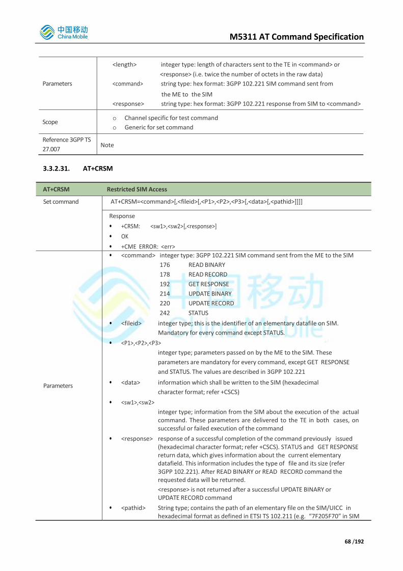
M5311 AT Command Specification
68 /192
Parameters
<length> integer type: length of characters sent to the TE in <command> or
<response> (i.e. twice the number of octets in the raw data)
<command> string type: hex format: 3GPP 102.221 SIM command sent from
the ME to the SIM
<response> string type: hex format: 3GPP 102.221 response from SIM to <command>
Scope o Channel specific for test command
o Generic for set command
Reference 3GPP TS
27.007 Note
3.3.2.31. AT+CRSM
AT+CRSM Restricted SIM Access
Set command AT+CRSM=<command>[,<fileid>[,<P1>,<P2>,<P3>[,<data>[,<pathid>]]]]
Response
• +CRSM: <sw1>,<sw2>[,<response>]
• OK
• +CME ERROR: <err>
Parameters
• <command> integer type: 3GPP 102.221 SIM command sent from the ME to the SIM
176 READ BINARY
178 READ RECORD
192 GET RESPONSE
214 UPDATE BINARY
220 UPDATE RECORD
242 STATUS
• <fileid> integer type; this is the identifier of an elementary datafile on SIM.
Mandatory for every command except STATUS.
• <P1>,<P2>,<P3>
integer type; parameters passed on by the ME to the SIM. These
parameters are mandatory for every command, except GET RESPONSE
and STATUS. The values are described in 3GPP 102.221
• <data> information which shall be written to the SIM (hexadecimal
character format; refer +CSCS)
• <sw1>,<sw2>
integer type; information from the SIM about the execution of the actual command. These parameters are delivered to the TE in both cases, on successful or failed execution of the command
• <response> response of a successful completion of the command previously issued (hexadecimal character format; refer +CSCS). STATUS and GET RESPONSE return data, which gives information about the current elementary datafield. This information includes the type of file and its size (refer 3GPP 102.221). After READ BINARY or READ RECORD command the requested data will be returned.
<response> is not returned after a successful UPDATE BINARY or UPDATE RECORD command
• <pathid> String type; contains the path of an elementary file on the SIM/UICC in hexadecimal format as defined in ETSI TS 102.211 (e.g. “7F205F70” in SIM

M5311 AT Command Specification
69 /192
and UICC case). The <pathid> only used in the mode “select path from MF” as defined in ETSI TS 102.211.
Scope o Channel specific for test command
o Generic for set command
Reference 3GPP TS
27.007
Note
• <pathid> is only valid for USIMs
o Since valid elementary file identifiers may not be unique over all valid dedicated file identifiers the <pathid> indicates the targeted UICC/SIM directory path in case of ambiguous file identifiers. For earlier versions of this specification or if <pathid> is omitted, it could be implementation specific which one will be selected.
3.3.2.32. AT+CSCS
AT+CSCS Select TE Character Set
Test command
AT+CSCS=?
Response
• +CSCS: (list of supported <chest>s)
Read command
AT+CSCS?
Response
• +CSCS: <chset> OK
Set command
AT+CSCS=[<chset>]
Response
• Sets which character set <chset> is used by the TE. The TA can then convert character strings correctly between the TE and ME character sets.
Parameter
<chset>
“GSM” GSM default alphabet.
“HEX” Hexadecimal numbers in character strings
“IRA” International reference alphabet (ITU-T T.50)
“PCCP” PC character set Code Page
“PCDN” PC Danish/Norwegian character set
“UCS2” UCS2 alphabet
“8859-1” ISO 8859 Latin (1) character set
Scope Channel specific
Reference 3GPP TS
27.007 Note
3.3.2.33. AT+CTZR
AT+CTZR Time Zone Reporting
Test command
AT+CTZR=?
Response
• +CTZR: (list of supported <onoff>s)
• OK
• If error is related to ME functionality:
o +CME ERROR: <err>

M5311 AT Command Specification
70 /192
Read command
AT+CTZR?
Response
• +CTZR: <onoff>
• OK
• If error is related to ME functionality:
o +CME ERROR: <err>
Set command
AT+CTZR=<onoff>
Response
• OK
• If error is related to ME functionality:
o +CME ERROR: <err> This set command enables and disables the time zone change event reporting. If the reporting is enabled the MT returns the unsolicited result code +CTZV: <tz> whenever the time zone is changed.
Parameter
<onoff>
0 Disable time zone change event reporting
1 Enable time zone change event reporting
2 Enable extended time zone and local time reporting by unsolicited result
code +CTZE: <tz>,<dst>,[<time>].
Scope Channel Specific
Reference
3GPP TS 27.007 Note
3.3.2.34. AT+CTZU
AT+CTZU Automatic Time Zone Update
Test command
AT+CTZU=?
Response
• +CTZU: (list of supported <onoff>s)
• OK
• If error is related to ME functionality:
o +CME ERROR: <err>
Read command
AT+CTZU?
Response
• +CTZU: <onoff> OK
• If error is related to ME functionality:
o +CME ERROR: <err>
Read command
AT+CTZU?
Response
• +CTZU: <onoff> OK
• If error is related to ME functionality:
o +CME ERROR: <err>
Set command
AT+CTZU=<onoff>
Response
• OK
• If error is related to ME functionality:
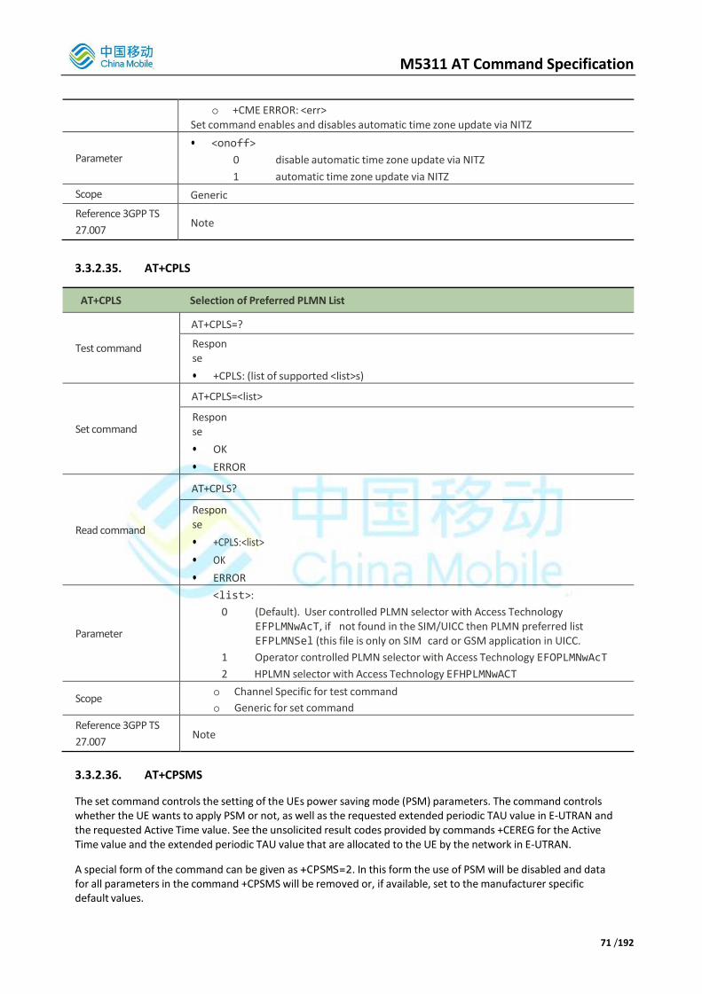
M5311 AT Command Specification
71 /192
o +CME ERROR: <err> Set command enables and disables automatic time zone update via NITZ
Parameter
• <onoff>
0 disable automatic time zone update via NITZ
1 automatic time zone update via NITZ
Scope Generic
Reference 3GPP TS
27.007 Note
3.3.2.35. AT+CPLS
AT+CPLS Selection of Preferred PLMN List
Test command
AT+CPLS=?
Response
• +CPLS: (list of supported <list>s)
Set command
AT+CPLS=<list>
Response
• OK
• ERROR
Read command
AT+CPLS?
Response
• +CPLS:<list>
• OK
• ERROR
Parameter
<list>:
0 (Default). User controlled PLMN selector with Access Technology EFPLMNwAcT, if not found in the SIM/UICC then PLMN preferred list EFPLMNSel (this file is only on SIM card or GSM application in UICC.
1 Operator controlled PLMN selector with Access Technology EFOPLMNwAcT
2 HPLMN selector with Access Technology EFHPLMNwACT
Scope o Channel Specific for test command
o Generic for set command
Reference 3GPP TS
27.007 Note
3.3.2.36. AT+CPSMS
The set command controls the setting of the UEs power saving mode (PSM) parameters. The command controls whether the UE wants to apply PSM or not, as well as the requested extended periodic TAU value in E-UTRAN and the requested Active Time value. See the unsolicited result codes provided by commands +CEREG for the Active Time value and the extended periodic TAU value that are allocated to the UE by the network in E-UTRAN.
A special form of the command can be given as +CPSMS=2. In this form the use of PSM will be disabled and data for all parameters in the command +CPSMS will be removed or, if available, set to the manufacturer specific default values.

M5311 AT Command Specification
72 /192
The read command returns the current parameter values.
The test command returns the supported <mode>s and the value ranges for the requested extended periodic TAU value in E-UTRAN and the requested Active Time value as compound values.
AT+CPSMS Power Saving Mode Setting
Test Command
AT+CPSMS=?
Response
• +CPSMS: (list of supported <mode>s),(list of supported <Requested_Periodic-RAU>s),(list of supported <Requested_GPRS-READY-timer>s),(list of supported <Requested_Periodic- TAU>s),(list of supported <Requested_Active-Time>s)
• OK
Read command
AT+CPSMS=?
Response
• +CPSMS:<mode>,[<Requested_Periodic-RAU>],[<Requested_GPRS-READY- timer>],[<Requested_Periodic-TAU>],[<Requested_Active-Time>]
• If error is related to wrong AT syntax or operation not allowed:
o +CME ERROR: <err>
Execution command
AT+CPSMS=[<mode>[,<Requested_Periodic-RAU>
[,<Requested_GPRS-READY- timer>[,<Requested_Periodic-TAU>[,<Requested_Active-Time>]]]]]
Response
• OK
• If error is related to wrong AT syntax:
o +CME ERROR: <err>
Parameters
• <mode>: integer type. Indication to disable or enable the use of PSM in the UE.
0 Disable the use of PSM
1 Enable the use of PSM
2 Disable the use of PSM and discard all parameters for PSM or, if available reset to the manufacturer specific default values.
• <Requested_Periodic-RAU>: N/A for NB-IoT
• <Requested_GPRS-READY-timer>: N/A for NB-IoT
• <Requested_Periodic-TAU>: string type; one byte in an 8-bit format. Requested extended periodic TAU value (T3412) to be allocated to the UE in E-UTRAN. The requested extended periodic TAU value is coded as one byte (octet 3) of the GPRS Timer 3 information element coded as bit format (e.g. "01000111" equals 70 hours). For the coding and the value range, see the GPRS Timer 3 IE in 3GPP TS 24.008 Table 10.5.163a/3GPP TS 24.008. See also 3GPP TS 23.682 and 3GPP TS 23.401. The default value, if available, is manufacturer specific.
• <Requested_Active-Time>: string type; one byte in an 8-bit format. Requested Active Time value (T3324) to be allocated to the UE. The requested Active Time value is coded as one byte (octet 3) of the GPRS Timer 2 information element coded as bit format (e.g. "00100100" equals 4 minutes). For the coding and the value range, see the GPRS Timer 2 IE in 3GPP TS 24.008 Table 10.5.163/3GPP TS 24.008. See also 3GPP TS 23.682, 3GPP TS 23.060 and 3GPP TS 23.401. The default value, if available, is manufacturer specific.
Scope Generic
Reference Note
3.3.2.37. AT+CIPCA
The set command controls whether an initial PDP context (see sub-clause 10.1.0) shall be established
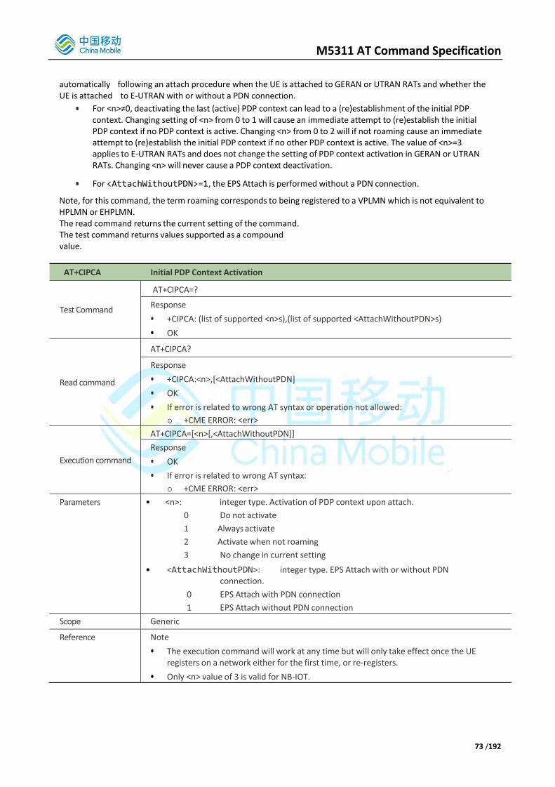
M5311 AT Command Specification
73 /192
automatically following an attach procedure when the UE is attached to GERAN or UTRAN RATs and whether the UE is attached to E-UTRAN with or without a PDN connection.
For <n>≠0, deactivating the last (active) PDP context can lead to a (re)establishment of the initial PDP context. Changing setting of <n> from 0 to 1 will cause an immediate attempt to (re)establish the initial PDP context if no PDP context is active. Changing <n> from 0 to 2 will if not roaming cause an immediate attempt to (re)establish the initial PDP context if no other PDP context is active. The value of <n>=3 applies to E-UTRAN RATs and does not change the setting of PDP context activation in GERAN or UTRAN RATs. Changing <n> will never cause a PDP context deactivation.
For <AttachWithoutPDN>=1, the EPS Attach is performed without a PDN connection.
Note, for this command, the term roaming corresponds to being registered to a VPLMN which is not equivalent to HPLMN or EHPLMN. The read command returns the current setting of the command. The test command returns values supported as a compound value.
AT+CIPCA Initial PDP Context Activation
Test Command
AT+CIPCA=?
Response
• +CIPCA: (list of supported <n>s),(list of supported <AttachWithoutPDN>s)
• OK
Read command
AT+CIPCA?
Response
• +CIPCA:<n>,[<AttachWithoutPDN]
• OK
• If error is related to wrong AT syntax or operation not allowed:
o +CME ERROR: <err>
Execution command
AT+CIPCA=[<n>[,<AttachWithoutPDN]]
Response
• OK
• If error is related to wrong AT syntax:
o +CME ERROR: <err>
Parameters • <n>: integer type. Activation of PDP context upon attach.
0 Do not activate
1 Always activate
2 Activate when not roaming
3 No change in current setting
• <AttachWithoutPDN>: integer type. EPS Attach with or without PDN connection.
0 EPS Attach with PDN connection
1 EPS Attach without PDN connection
Scope Generic
Reference Note
• The execution command will work at any time but will only take effect once the UE registers on a network either for the first time, or re-registers.
• Only <n> value of 3 is valid for NB-IOT.

M5311 AT Command Specification
74 /192
3.3.2.38. AT+CCIOTOPT
The set command controls which CIoT EPS optimizations the UE indicates as supported and preferred in the ATTACH REQUEST and TRACKING AREA UPDATE REQUEST messages. The command also allows reporting of the CIoT EPS optimizations that are supported by the network. A UE supporting CIoT functionality may support control plane CIoT EPS optimization or user plane CIoT EPS optimization or both (see 3GPP TS 24.301, sub-clause 9.9.3.34). Based on the application characteristics the UE may prefer to be registered for control plane CIoT EPS optimization or for user plane CIoT EPS optimization (see 3GPP TS 24.301, sub-clause 9.9.3.0B).
Further the network may support control plane CIoT EPS optimization or user plane CIoT EPS optimization or both (see 3GPP TS 24.301, sub-clause 9.9.3.12A).
The set command is used also to control the unsolicited result code +CCIOTOPTI. An unsolicited result code
+CCIOTOPTI: <supported_Network_opt> is used to indicate the supported CIoT EPS optimizations by the network.
The read command returns the current settings for supported and preferred CIoT EPS optimizations and the current status of unsolicited result code +CCIOTOPTI.
AT+CCIOTOPT CIoT Optimization Configuration
Test Command
AT+CCIOTOPT=?
Response
• +CCIOTOPT: (list of supported <n>s),(list of supported <supported_UE_opt>s),(list of supported <preferred_UE_opt>s)
• OK
Read command
AT+CCIOTOPT?
Response
• +CCIOTOPT:<n>,<supported_UE_opt>,<preferred_UE_opt>
Execution command
AT+CCIOTOPT=[<n>,[<supportedUE_opt>[,<preferred_UE_opt>]]]
Response
• OK
• If error is related to wrong AT syntax:
o +CME ERROR: <err>
Unsolicited result
code
+CCIOTOPTI: <supported_Network_opt> is used to indicate the supported CIoT EPS optimizations by the network.
Parameters • <n>: integer type, enables or disables reporting of unsolicited result code +CCIOTOPTI.
0 Disable reporting.
1 Enable reporting.
3 Disable reporting and reset the parameters for CIoT EPS optimization to the default values.
• <supported_UE_opt>: integer type; indicates the UE's support for CIoT EPS optimizations.
0 No support
1 Support for control plane CIoT EPS optimization.
2 Support for user plane CIoT EPS optimization.
3 Support for both control plane CIoT EPS optimization and user plane CIoT EPS optimization.
• <preferred_UE_opt>: integer type; indicates the UE's preference for CIoT EPS
optimizations.
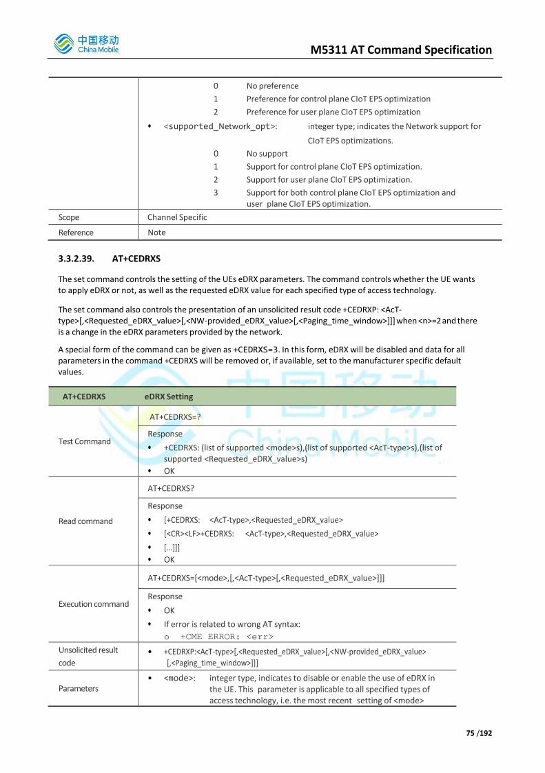
M5311 AT Command Specification
75 /192
0 No preference
1 Preference for control plane CIoT EPS optimization
2 Preference for user plane CIoT EPS optimization
• <supported_Network_opt>: integer type; indicates the Network support for
CIoT EPS optimizations.
0 No support
1 Support for control plane CIoT EPS optimization.
2 Support for user plane CIoT EPS optimization.
3 Support for both control plane CIoT EPS optimization and user plane CIoT EPS optimization.
Scope Channel Specific
Reference Note
3.3.2.39. AT+CEDRXS
The set command controls the setting of the UEs eDRX parameters. The command controls whether the UE wants to apply eDRX or not, as well as the requested eDRX value for each specified type of access technology.
The set command also controls the presentation of an unsolicited result code +CEDRXP: <AcT- type>[,<Requested_eDRX_value>[,<NW-provided_eDRX_value>[,<Paging_time_window>]]] when <n>=2 and there is a change in the eDRX parameters provided by the network.
A special form of the command can be given as +CEDRXS=3. In this form, eDRX will be disabled and data for all parameters in the command +CEDRXS will be removed or, if available, set to the manufacturer specific default values.
AT+CEDRXS eDRX Setting
Test Command
AT+CEDRXS=?
Response
• +CEDRXS: (list of supported <mode>s),(list of supported <AcT-type>s),(list of supported <Requested_eDRX_value>s)
• OK
Read command
AT+CEDRXS?
Response
• [+CEDRXS: <AcT-type>,<Requested_eDRX_value>
• [<CR><LF>+CEDRXS: <AcT-type>,<Requested_eDRX_value>
• [...]]]
• OK
Execution command
AT+CEDRXS=[<mode>,[,<AcT-type>[,<Requested_eDRX_value>]]]
Response
• OK
• If error is related to wrong AT syntax:
o +CME ERROR: <err>
Unsolicited result
code • +CEDRXP:<AcT-type>[,<Requested_eDRX_value>[,<NW-provided_eDRX_value>
[,<Paging_time_window>]]]
Parameters • <mode>: integer type, indicates to disable or enable the use of eDRX in
the UE. This parameter is applicable to all specified types of access technology, i.e. the most recent setting of <mode>

M5311 AT Command Specification
76 /192
will take effect for all specified values of <AcT>.
0 Disable the use of eDRX
1 Enable the use of eDRX
2 Enable the use of eDRX and enable the unsolicited result code +CEDRXP: <AcT-type>[,<Requested_eDRX_value>[,<NW-provided_eDRX_value>[,<Paging_time_window>]]]
3 Disable the use of eDRX and discard all parameters for eDRX or, if available, reset to the manufacturer specific default values.
• <AcT-type>: integer type, indicates the type of access technology. This AT-command is used to specify the relationship between the type of access technology and the requested eDRX value.
0 Access technology is not using eDRX. This parameter value is only used in the unsolicited result code.
5 E-UTRAN (NB-S1 mode)
• <Requested_eDRX_value>: string type; half a byte in a 4-bit format. The eDRX valuerefers to bit 4 to 1 of octet 3 of the Extended DRX parameters information element (see sub-clause 10.5.5.32 of 3GPP TS 24.008). For the coding and the value range,see Extended DRX parameters information element in 3GPP TS 24.008 Table 10.5.5.32/3GPP TS 24.008. The default value, if available, is manufacturer specific.
• <NW-provided_eDRX_value>: string type; half a byte in a 4-bit format. The eDRX value refers to bit 4 to 1 of octet 3 of the Extended DRX parameters information element (see sub-clause 10.5.5.32 of 3GPP TS 24.008). For the coding and the value range, see Extended DRX parameters information element in 3GPP TS 24.008 Table 10.5.5.32/3GPP TS 24.008.
• <Paging_time_window>: string type; half a byte in a 4-bit format. The paging time window refers to bit 8 to 5 of octet 3 of the Extended DRX parameters information element (see sub-clause 10.5.5.32 of 3GPP TS 24.008). For the coding and the value range, see the Extended DRX parameters information element in 3GPP TS 24.008 Table 10.5.5.32/3GPP TS 24.008.
Scope Generic
Reference Note
3.3.2.40. AT+CEDRXRDP
The execution command returns <AcT-type> and <Requested_eDRX_value>, <NW-provided_eDRX_value> and <Paging_time_window> if eDRX is used for the cell that the MS is currently registered to.
If the cell that the MS is currently registered to is not using eDRX, AcT-type=0 is returned.
AT+CEDRXRDP eDRX Read Dynamic Parameters
Execution command
AT+CEDRXRDP
Response
• +CEDRXRDP: <AcT-type>[,<Requested_eDRX_value>[,<NW- provided_eDRX_value>

M5311 AT Command Specification
77 /192
[,<Paging_time_window>]]]
• OK
Parameters • <AcT-type>: integer type, indicates the type of access technology. This AT-command is used to specify the relationship between the type of access technology and the requested eDRX value.
0 Access technology is not using eDRX
4 E-UTRAN (NB-S1 mode)
• <Requested_eDRX_value>: string type; half a byte in a 4-bit format. The eDRX value refers to bit 4 to 1 of octet 3 of the Extended DRX parameters information element (see sub-clause 10.5.5.32 of 3GPP TS 24.008). For the coding and the value range, see Extended DRX parameters information element in 3GPP TS 24.008 Table 10.5.5.32/3GPP TS 24.008.
• <NW-provided_eDRX_value>: string type; half a byte in a 4-bit format. The eDRX value refers to bit 4 to 1 of octet 3 of the Extended DRX parameters information element (see sub-clause 10.5.5.32 of 3GPP TS 24.008). For the coding and the value range, see Extended DRX parameters information element in 3GPP TS 24.008 Table 10.5.5.32/3GPP TS 24.008.
• <Paging_time_window>: string type; half a byte in a 4-bit format. The paging time window refers to bit 8 to 5 of octet 3 of the Extended DRX parameters information element (see sub-clause 10.5.5.32 of 3GPP TS 24.008). For the coding and the value range, see the Extended DRX parameters information element in 3GPP TS 24.008 Table 10.5.5.32/3GPP TS 24.008.
Scope Generic
Reference Note
3.3.2.41. AT+CGAPNRC
This execution command returns the APN rate control parameters (see 3GPP TS 24.008) associated to the provided context identifier <cid>.
If the parameter <cid> is omitted, the APN rate control parameters for all active PDP contexts are returned. The test command returns a list of <cid>s associated with secondary and non-secondary active PDP contexts.
AT+CGAPNRC APN Rate Control
Test Command
AT+CGAPNRC=?
Response
• +CGAPNRC: (list of <cid>s associated with active contexts)
• OK
Execution command
AT+CGAPNRC[=<cid>]
Response
• [+CGAPNRC: <cid>[,<Additional_exception_reports>[,<Uplink_time_unit>[, <Maxim um_uplink_rate>]]]
• [<CR><LF>+CGAPNRC: <cid>[,<Additional_exception_reports>[, <Uplink_time_unit>[,<Maximum_uplink_rate>]]]
• [...]]]
• OK
Parameters • <cid>: integer type; specifies a particular PDP context definition (see the +CGDCONT and +CGDSCONT commands).

M5311 AT Command Specification
78 /192
• <Additional_exception_reports>: integer type; indicates whether an additional exception reports are allowed to send when the maximum uplink rate is reached. This refers to bit 4 of octet 1 of the APN rate control parameters IE as specified in 3GPP TS 24.008 sub-clause 10.5.6.3.2.
0 Additional_exception_reports at maximum rate reached are not allowed to be sent.
1 Additional_exception_reports at maximum rate reached are allowed to send.
• <Uplink_time_unit>: integer type; specifies the time unit to be used for the maximum uplink rate. This refers to bits 1 to 3 of octet 1 of the APN rate control parameters IE as specified in 3GPP TS 24.008 sub-clause 10.5.6.3.2.
0 unrestricted
1 minute
2 hour
3 day
4 week
• <Maximum_uplink_rate>: integer type; specifies the maximum number of messages the UE is restricted to send per uplink time unit. This refers to octet 2 to 4 of the APN rate control parameters IE as specified in 3GPP TS 24.008 sub-clause 10.5.6.3.2.
Scope Generic
Reference Note
3.3.2.42. AT+CSCON
The set command controls the presentation of an unsolicited result code +CSCON. If <n>=1, +CSCON: <mode> is sent from the MT when the connection mode of the MT is changed.
For NB-IoT, only <n>=1 is supported.
The mode of the MT refers to idle when no PS signaling connection and to connected mode when a PS signaling connection between UE and network is setup.
The read command returns the status of result code presentation and an integer <mode> which shows whether the MT is currently in idle mode or connected mode.
Test command returns supported values as a compound value.
AT+CSCON Signaling Connection Status
Test Command
AT+CSCON=?
Response
• +CSCON: (list of <n>s)
• OK
Read command
AT+CSCON?
Response
• +CSCON: <n>,<mode>[,<state>]
• OK
• If error is related to wrong AT syntax:
o +CME ERROR: <err>

M5311 AT Command Specification
79 /192
Execution command
AT+CSCON[=<n>]
Response
• OK
• If error is related to wrong AT syntax:
o +CME ERROR: <err>
Unsolicited result code +CSCON: <mode>[<state>[<access>]]
Parameters
• <n>: integer type:
0 disable unsolicited result code
1 enable unsolicited result code +CSCON: <mode>
• <mode>: integer type; indicates signaling connection status
0 idle
1 connected
Scope Channel specific
Reference Note
• <state> and <access> parameters not supported for NB-IoT
3.3.2.43. AT+CCHO
Execution of this command causes the MT to return <sessionid> to allow the TE to identify a channel that is being allocated by the currently selected UICC, which is attached to ME. The currently selected UICC will open a new logical channel; select the application identified by the <dfname> received with this command and return a session Id as the response. The ME restricts the communication between the TE and the UICC to this logical channel.
This <sessionid> is used when sending commands with Generic UICC Logical Channel access +CGLA commands.
AT+CCHO Open UICC Logical Channel
Execution command
AT+CCHO=<dfname>
Response
• <sessionid>
• OK
• If error is related to wrong AT syntax:
o +CME ERROR: <err>
Parameters
• <dfname>: String type in hexadecimal character format. All selectable applications in the
UICC are referenced by a DF name coded on 1 to 16 bytes
• <sessionid>: integer type; a session Id to be used to target a specific application on the
smart card (e.g. (U)SIM, WIM, ISIM) using logical channels mechanism
• See 3GPP TS 31.101 for more information about defined values.
Scope Channel Specific
Reference Note
3.3.2.44. AT+CCHC
This command asks the ME to close a communication session with the active UICC. The ME closes the previously opened logical channel. The TE will no longer be able to send commands on this logical channel. The UICC will close the logical channel when receiving this command.

M5311 AT Command Specification
80 /192
AT+CCHC Close UICC Logical Channel
Execution command
AT+CCHC=<sessionid>
Response
• CCHC
• OK
• If error is related to wrong AT syntax:
o +CME ERROR: <err>
Parameters • <sessionid>: integer type; the session used to target a specific application
on the smart card (e.g. (U)SIM, WIM, ISIM) using logical channels mechanism
• See 3GPP TS 31.101 for more information about defined values.
Scope Channel Specific
Reference Note
3.3.2.45. AT+CGLA
Set command transmits to the MT the <command> is sent as is to the selected UICC. The UICC <response> is sent back by the MT to the TA as is.
This command allows a direct control of the currently selected UICC by a distant application on the TE. Although
+CGLA allows the TE to take control over the UICC-MT interface, there are some functions of the UICC-MT interface that logically do not need to be accessed from outside the TA/MT and, for security reasons the GSM
network authentication should not be handled outside the TA/MT. So, a Run GSM Algorithm command or an Authenticate command in GSM context shall not be allowed whether the +CGLA is locked or unlocked. However, the TE may send Authenticate commands in other security contexts (e.g. EAP security context).
AT+CGLA Generic UICC Logical Channel Access
Execution command
AT+CGLA=<sessionid>,<length>,<command>
Response
• +CGLA: <length>,<response>
• OK
• If error is related to wrong AT syntax:
o +CME ERROR: <err>
Parameters
• <sessionid> integer type; this is the identifier of the session used to send
the APDU commands to the UICC. It is mandatory to send
commands to the UICC when targeting applications on the
smart card using a logical channel other than the default
channel (channel "0").
• <length> integer type; length of the characters that are sent to TE in
<command> or <response> (two times the actual length of the
command or response)
• <command> command passed on by the MT to the UICC in the format as
described in 3GPP TS 31.101 (hexadecimal character format)
• <response> : response to the command passed on by the UICC to the MT in
the format as described in 3GPP TS 31.101 (hexadecimal
character format)
Scope Channel Specific

M5311 AT Command Specification
81 /192
Reference Note
3.3.2.46. AT+CRLA
AT+CRLA UICC logical channel access
Execution command
AT+CRLA=<sessionid>, <command>[,<fileid> [,<P1>,<P2>,<P3>[,<data>[,<pathid>]]]]
Response
• +CGLA: <sw1>,<sw2>[,<response>]
• OK
• +CME ERROR: <err>
Parameters
• <sessionid> integer type; this is the identifier of the session used to send
the APDU commands to the UICC. It is mandatory to send
commands to the UICC when targeting applications on the
smart card using a logical channel other than the default
channel (channel "0").
• <command> integer type: 3GPP 102.221 SIM command sent from the ME
to the SIM.
176 READ BINARY
178 READ RECORD
192 GET RESPONSE
214 UPDATE BINARY
220 UPDATE RECORD
242 STATUS
• <fileid> integer type; this is the identifier of an elementary datafile on
SIM. Mandatory for every command except STATUS.
• <P1>,<P2>,<P3> integer type; parameters passed on by the ME to the SIM.
These parameters are mandatory for every command, except
GET RESPONSE and STATUS. The values are described in 3GPP
102.221
• <data> information which shall be written to the SIM (hexadecimal
character format; refer +CSCS)
• <sw1>,<sw2> integer type; information from the SIM about the execution of
the actual command. These parameters are delivered to the TE
in both cases, on successful or failed execution of the command
• <response> response of a successful completion of the command
previously issued (hexadecimal character format; refer +CSCS).
STATUS and GET RESPONSE return data, which gives
information about the current elementary datafield. This
information includes the type of file and its size (refer 3GPP
102.221). After READ BINARY or READ RECORD command the
requested data will be returned. <response> is not returned
after a successful UPDATE BINARY or UPDATE RECORD
command
Scope o Channel Specific for test command
o Generic for set command
Reference Note
• <pathid> is only valid for USIMs

M5311 AT Command Specification
82 /192
o Since valid elementary file identifiers may not be unique over all valid
dedicated file identifiers the <pathid> indicates the targeted UICC/SIM
directory path in case of ambiguous file identifiers. For earlier versions of
this specification or if <pathid> is omitted, it could be implementation
specific which one will be selected.
3.3.2.47. AT+CPINR
Execution command cause the UE to return the number of remaining PIN retries for the UE passwords with intermediate result code +CPINR: <code>,<retries>[,<default_retries>] for standard PINs and +CPINRE: <ext_code>,<retries>[,<default_retries>] for manufacturer specific PINs. One line with one intermediate result code is returned for every <code> or <ext_code> selected by <sel_code>.
When execution command is issued without the optional parameter <sel_code>, intermediate result codes are returned for all <code>s and <ext_code>s.
In the intermediate result codes, the parameter <default_retries> is an optional (manufacturer specific) parameter, per <code> and <ext_code>.
Note that the M5311 modem does not support the +CPINRE indication.
AT+CPINR Remaining PIN Retries
Execution Command
AT+CPINR[=<sel_code>]
Response
• [+CPINR: <code>,<retries>,[<default_retries>]
• [<CR>,<LF>:CPINR: <code>,<retries>,[default_retries>
• […]]
• OK
• If error is related to wrong AT syntax:
o +CME ERROR: <err>
Parameters
• <sel_code>: String type. Same values as for the <code> parameter. These values are strings and shall be indicated within double quotes. Wildcard match by ‘*’, meaning match any (sub-)string, or ‘?’ meaning an character can be used.
• <retries>: Integer type. Number of remaining retries per PIN.
• <default_retries>: Integer type. Number of default/initial retries per PIN.
• <code>: Type of PIN. All values listed under the description of the AT+CPIN Command, <code> parameter except “READY”.
Scope Generic
Reference
Note
• M5311 modem does not support the +CPINRE indication.
• “SIM UPIN” and “SIM UPUK” are used to display the universal PIN values if the USIM supports it.
+CPINR examples
AT+CPINR=? Test command
OK
AT+CPINR? Read command
ERROR
AT+CPINR=”SIM*” Execute command. Read all SIM PIN retries

M5311 AT Command Specification
83 /192
starting with the string “SIM”.
+CPINR: “SIM PIN”,3,3
+CPINR: “SIM PUK”,10.10
+CPINR: “SIM PIN2”,3,3
+CPINR: “SIM PUK2”,10,10
+CPINR: “SIM UPIN”,3,3
+CPINR: “SIM UPUK”,10,10 OK
AT+CPINR Execute command. Read all SIM PIN retries
starting with the string “SIM”.
+CPINR: “SIM PIN”,3,3
+CPINR: “SIM PUK”,10.10
+CPINR: “SIM PIN2”,3,3
+CPINR: “SIM PUK2”,10,10
+CPINR: “SIM UPIN”,3,3
+CPINR: “SIM UPUK”,10,10 OK
AT+CPINR=”SIM PIN*” Execute command. Read all SIM PIN retries
starting with the string “SIM PIN”.
+CPINR: “SIM PIN”,3,3
+CPINR: “SIM PIN2”,3,3 OK
3.3.2.48. AT+CGPIAF
Set command decides what format to print IPV6 address parameters of other AT commands. See RFC 4291 for details of the IPv6 address format.
The +CGPIAF parameters <IPv6_AddressFormat>, <IPv6_SubnetNotation>, <IPv6_LeadingZeros> and
<IPv6_CompressedZeros> affect the following commands and parameters:
1) in +CGTFT and +CGTFTRDP, the <source address and subnet mask>;
2) in +CGDCONT, the <PDP_addr>;
3) in +CGPADDR, the <PDP_addr_1> and <PDP_addr_2>;
4) in +CGCONTRDP, the <source address and subnet mask>, <DNS_prim_addr>, <DNS_sec_addr>, <P_CSCF_prim_addr> and <P_CSCF_sec_addr>;
Read command returns the current command parameter settings. Test command returns values supported as compound values.
AT+CGPIAF Printing IP Address Format
Test Command
AT+CGPIAF=?
Response
• +CGPIAF: (list of supported <IPv6_AddressFormat>s), (list of supported <IPv6_SubnetNotation>s), (list of supported IPv6_LeadingZeros>s), (list of supported IPv6_CompressZeros>s)
• OK
Read Command
AT+CGPIAF?
Response
• +CGPIAF: <IPv6_AddressFormat>,<IPv6_SubnetNotation>,<IPv6_LeadingZeros>,
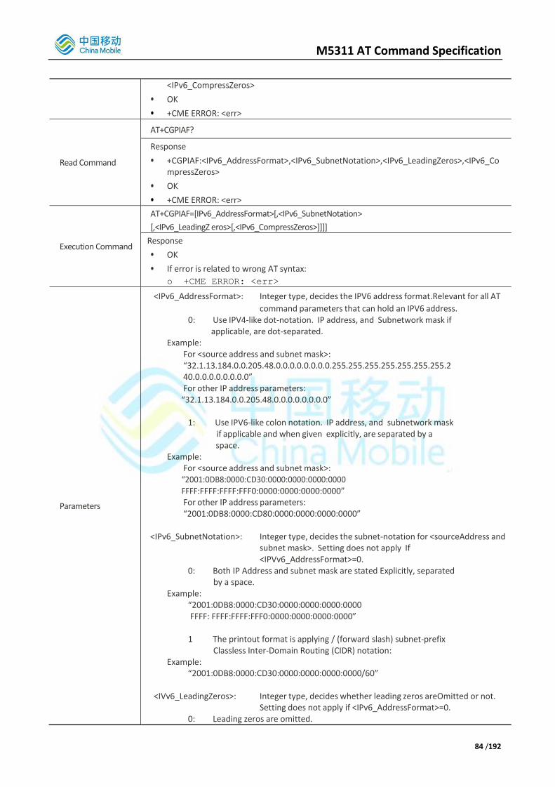
M5311 AT Command Specification
84 /192
<IPv6_CompressZeros>
• OK
• +CME ERROR: <err>
Read Command
AT+CGPIAF?
Response
• +CGPIAF:<IPv6_AddressFormat>,<IPv6_SubnetNotation>,<IPv6_LeadingZeros>,<IPv6_CompressZeros>
• OK
• +CME ERROR: <err>
Execution Command
AT+CGPIAF=[IPv6_AddressFormat>[,<IPv6_SubnetNotation>
[,<IPv6_LeadingZ eros>[,<IPv6_CompressZeros>]]]]
Response
• OK
• If error is related to wrong AT syntax:
o +CME ERROR: <err>
Parameters
<IPv6_AddressFormat>: Integer type, decides the IPV6 address format.Relevant for all AT
command parameters that can hold an IPV6 address. 0: Use IPV4-like dot-notation. IP address, and Subnetwork mask if
applicable, are dot-separated. Example:
For <source address and subnet mask>: “32.1.13.184.0.0.205.48.0.0.0.0.0.0.0.0.255.255.255.255.255.255.255.2 40.0.0.0.0.0.0.0.0” For other IP address parameters:
“32.1.13.184.0.0.205.48.0.0.0.0.0.0.0.0”
1: Use IPV6-like colon notation. IP address, and subnetwork mask if applicable and when given explicitly, are separated by a space.
Example: For <source address and subnet mask>: “2001:0DB8:0000:CD30:0000:0000:0000:0000 FFFF:FFFF:FFFF:FFF0:0000:0000:0000:0000” For other IP address parameters: “2001:0DB8:0000:CD80:0000:0000:0000:0000”
<IPv6_SubnetNotation>: Integer type, decides the subnet-notation for <sourceAddress and subnet mask>. Setting does not apply If <IPVv6_AddressFormat>=0.
0: Both IP Address and subnet mask are stated Explicitly, separated by a space.
Example: “2001:0DB8:0000:CD30:0000:0000:0000:0000 FFFF: FFFF:FFFF:FFF0:0000:0000:0000:0000” 1 The printout format is applying / (forward slash) subnet-prefix
Classless Inter-Domain Routing (CIDR) notation: Example:
“2001:0DB8:0000:CD30:0000:0000:0000:0000/60”
<IVv6_LeadingZeros>: Integer type, decides whether leading zeros areOmitted or not. Setting does not apply if <IPv6_AddressFormat>=0.
0: Leading zeros are omitted.

M5311 AT Command Specification
85 /192
Example: “2001:DB8:0:CD30:0:0:0:0” 1: Leading zeros are included.
Example: “2001:0DB8:0000:CD30:0000:0000:0000:0000”
<IPv6_CompressZeros>: Integer type, decides whether 1-n instances of 16 bit zero-values are replaced by only “..”. This Applies only once. Setting does not apply if <IPv6_AddressFormat>=0.
0: No zero compression. Example:
“2001:DB8:0:CD30:0:0:0:0” 1 Use zero compression.
Example: “2001:DB8:0:CD30::”
Scope Channel Specific
Reference
Note
• M5311 modem does not support the +CPINRE indication.
• “SIM UPIN” and “SIM UPUK” are used to display the universal PIN values if the USIM supports it.
+CGPIAF examples
AT+CGPIAF=? Test command
+CGPIAF: (0,1),(0,1),(0,1),(0,1)
OK
AT+CGPIAF? Read command
+CGPIAF: 0,0,0,0 All Settings at default format
OK
AT+CGPIAF=1,1,0,1 Set command. Use IPV6-like notation, with
the “/” format for subnet mask, omit leading zeros and use zero compression.
OK
3.3.2.49. AT+CGEREP
Set command enables or disables sending of unsolicited result codes, +CGEV: XXX from UE to TE in the case of
certain events occurring in the Packet Domain UE or the network. <mode> controls the processing of unsolicited result codes specified within this command. <bfr> controls the effect on buffered codes when <mode> 1 or 2 is entered.
Read command returns the current mode and buffer settings.
Test command returns the modes and buffer settings supported by the UE as compound values.
AT+CGEREP Packet Domain Event Reporting
Test Command
AT+CGEREP=?
Response
• +CGEREP: (list of supported <mode>s), (list of supported <bfr>s)
• OK
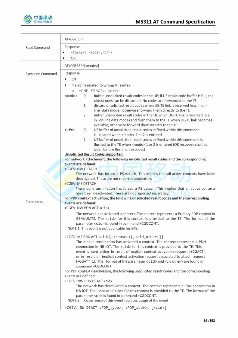
M5311 AT Command Specification
86 /192
Read Command
AT+CGEREP?
Response
• +CGEREP: <mode>,<bfr>
• OK
Execution Command
AT+CGEREP=[<mode>]
Response
• OK
• If error is related to wrong AT syntax:
o +CME ERROR: <err>
Parameters
<mode> 0 buffer unsolicited result codes in the UE; if UE result code buffer is full, the oldest ones can be discarded. No codes are forwarded to the TE.
1 discard unsolicited result codes when UE-TE link is reserved (e.g. in on-line data mode); otherwise forward them directly to the TE
2 buffer unsolicited result codes in the UE when UE-TE link is reserved (e.g. in on-line data mode) and flush them to the TE when UE-TE link becomes available; otherwise forward them directly to the TE
<bfr> 0 UE buffer of unsolicited result codes defined within this command is cleared when <mode> 1 or 2 is entered
1 UE buffer of unsolicited result codes defined within this command is flushed to the TE when <mode> 1 or 2 is entered (OK response shall be given before flushing the codes)
Unsolicited Result Codes supported: For network attachment, the following unsolicited result codes and the corresponding events are defined: +CGEV: NW DETACH
The network has forced a PS detach. This implies that all active contexts have been deactivated. These are not reported separately.
+CGEV: ME DETACH The mobile termination has forced a PS detach. This implies that all active contexts have been deactivated. These are not reported separately.
For PDP context activation, the following unsolicited result codes and the corresponding events are defined: +CGEV: NW PDN ACT <cid>
The network has activated a context. The context represents a Primary PDP context in GSM/UMTS. The <cid> for this context is provided to the TE. The format of the parameter <cid> is found in command +CGDCONT.
NOTE 1: This event is not applicable for EPS.
+CGEV: ME PDN ACT <cid>[,<reason>[,<cid_other>]] The mobile termination has activated a context. The context represents a PDN connection in NB-IOT. The <cid> for this context is provided to the TE. This event is sent either in result of explicit context activation request (+CGACT), or in result of implicit context activation request associated to attach request (+CGATT=1). The format of the parameter <cid> and <cid other> are found in command +CGDCONT.
For PDP context deactivation, the following unsolicited result codes and the corresponding events are defined:
+CGEV: NW PDN DEACT <cid> The network has deactivated a context. The context represents a PDN connection in NB-IOT. The associated <cid> for this context is provided to the TE. The format of the parameter <cid> is found in command +CGDCONT.
NOTE 2: Occurrence of this event replaces usage of the event
+CGEV: NW DEACT <PDP_type>, <PDP_addr>, [<cid>]

M5311 AT Command Specification
87 /192
+CGEV: ME PDN DEACT <cid> The mobile termination has deactivated a context. The context represents a PDN connection in NB-IOT. The <cid> for this context is provided to the TE. The format of the parameter <cid> is found in command +CGDCONT.
NOTE 3: Occurrence of this event replaces usage of the event
+CGEV: ME DEACT <PDP_type>, <PDP_addr>, [<cid>]
For other PDP context handling, the following unsolicited result codes and the corresponding events are defined:
+CGEV: REJECT <PDP_type>, <PDP_addr> A network request for context activation occurred when the UE was unable to report it to the TE with a +CRING unsolicited result code and was automatically rejected. The format of the parameters <PDP_type> and <PDP_addr> are found in command +CGDCONT.
NOTE 6: This event is not applicable for EPS.
+CGEV: NW REACT <PDP_type>, <PDP_addr>, [<cid>] The network has requested a context reactivation. The <cid> that was used to reactivate the context is provided if known to the UE. The format of the parameters <PDP_type>, <PDP_addr> and <cid> are found in command +CGDCONT.
NOTE 7: This event is not applicable for EPS.
Parameter:
<PDP_type> Packet Data Protocol type (see +CGDCONT command) <PDP_addr> Packet Data Protocol address (see +CGDCONT command} <cid> Context Id (see +CGDCONT command) Note: <cid> only given if known
to the UE. <class> GPRS mobile class (see +CGCLASS command) <event_type> Integer type parameter indicates whether this is an
informational Event of whether the TE as acknowledged it. 0 Informational event 1 Information request: Acknowledgement required. The
Acknowledgement can be accept or reject, see AT+CGANS.
<change_reason> Integer type parameter indicates what kind of change occurred.
1 TFT only changed 2 QoS only changed 3 Both TFT and QoS changed
<reason> Integer type parameter indicates the reason why the context activation request for PDP type IPV4V6 was not granted. This parameter is only included if the requested PDP type associated with <cid> is IPV4V6, and the PDP type assign by the network for <cid> is either IPV4 or IPV6 0 IPV4 only allowed 1 IPV6 only allowed 2 single address bearers only allowed 3 single address bearers only allowed and MT initiated
context activation for a second address type bearer was not successful
<cid_other> Indicated the context identifier allocated by MT for an MT initiated context of a second address type. MT shall only include this parameter if <reason> parameter indicates single address bearers only allowed, and MT support MT initiated context activation of a second address type without additional commands from the TE, and MT has activated the PDN connection or PDP context associated with <cid_other>.

M5311 AT Command Specification
88 /192
Scope Channel Specific
Reference
Note
• Parameter <mode> option 2 is not supported.
• Parameter <cid_other> is not supported by NB-IOT modem software.
3.3.2.50. AT+CGDEL
The execution command +CGDEL=<cid> removes the indicated PDP context and removes all associated data related to the indicated PDP contexts that are not activated. The AT command will not delete or remove information for activated PDP contexts. The removed PDP context is listed by the +CGDEL: <cid> intermediate result code.
If <cid> points to a primary PDP context, the PDP context will be deleted together with all linked secondary PDP contexts if none of the PDP contexts are activated.
If <cid> points to a secondary PDP context, the PDP context will be deleted if it is not activated.
A special form of the command can be given as +CGDEL (with the =<cid> omitted). In this form, all primary PDP contexts that are not activated or have any activated secondary PDP contexts will be removed and all secondary PDP contexts that are not activated will be removed. The associated data of all the deleted PDP contexts will be removed, and the removed PDP context are listed by the +CGDEL: <cid>[,<cid>[,...]] intermediate result code. Activated PDP contexts will not cause this form of the command to return ERROR or +CME ERROR.
Note, +CGDEL will remove associated PDP context data that can be set by the AT commands +CGDCONT, +CGDSCONT, +CGTFT, +CGEQREQ, +CGEQMIN and +CGEQOS.
For an attempt to delete PDP context(s) which would violate these rules, a +CME ERROR response is returned. Refer sub-clause 9.2 for possible <err> values.
AT+CGDEL Delete Non-Active PDP Contexts
Execution Command
AT+CGDEL=<cid>
Response
• +CGDEL: <cid>[,<cid>[,…]]
• OK
• If error is related to wrong AT syntax:
o +CME ERROR: <err>
Parameters <cid>: a numeric parameter which specifies a particular PDP context Definition.
Scope Generic
Reference Note
3.3.2.51. AT+CGAUTH
Set command allows the user to specify authentication parameters for a PDP context identified by the (local) context identification parameter <cid> used during the PDP context activation and the PDP context modification procedures. Since the <cid> is the same parameter that is used in the +CGDCONT and +CGDSCONT commands, +CGAUTH is effectively as an extension to these commands.
Note, this AT command transfers information in the clear that can be regarded as sensitive in security terms. Care must be exercised in providing this command where the AT commands are used in insecure scenarios. The read command returns the current settings for each defined context.
The test command returns values supported as a compound value.

M5311 AT Command Specification
89 /192
AT+CGAUTH Define PDP Context Authentication Parameters
Test Command
AT+CGAUTH=?
Response
• +CGAUTH: (range of supported <cid>s),(list of supported <auth_prot>s),(range of supported <userid>s),(range of supported <password>s)
• OK
Read Command
AT+CGAUTH?
Response
• [+CGAUTH: <cid>,<auth_prot>,<userid>,<password>]
• [<CR><LF>+CGAUTH: <cid>,<auth_prot>,<userid>,<password>
• […]]
• OK
Execution Command
AT+CGAUTH=<cid>[,<auth_prot>[,<userid>[,<password>]]]
Response
• When <auth_prot>/<username>/<password> set:
o OK
• When no <auth_prot>/<username>/<password> set displays current auth_prot
username and password for <cid>:
o +CGAUTH:<cid>,<auth_prot>,<username>,<password>
o OK
• OK
• If error is related to wrong AT syntax:
o +CME ERROR: <err>
Parameters
<cid>: A numeric parameter which specifies a particular PDPcontext definition (see the +CGDCONT and +CGDSCONT commands).
<auth_prot>: Numeric parameter. Authentication protocol used for this PDP context. 0: None. Used to indicate that no authentication
protocol is used for this PDP context. Username and password are removed if previously specified.
1: PAP <userid>: String type. User name for access to the IP network. <password>: String type. Password for access to the IP network.
Scope Generic
Reference Note
• M5311 only supports <auth_prot> = PAP

M5311 AT Command Specification
90 /192
3.4. AT Commands According to 3GPP TS 27.005 for SMS
3.4.1. Overview
The 3GPP TS 27.005 commands are for performing SMS and CBS related operations for both Text and PDU modes.
Command Description
AT+CMGD Delete SMS Message
AT+CMGF Select SMS Message Format
AT+CMGL List SMS Messages From Preferred Store
AT+CMGR Read SMS Message
AT+CMGS Send SMS Message
AT+CMGW Write SMS Message To Memory
AT+CMSS Send SMS Message From Storage
AT+CMGC Send SMS Command
AT+CNMI New SMS Message Indications
AT+CPMS Preferred SMS Message Storage
AT+CRES Restore SMS Settings
AT+CSAS Save SMS Settings
AT+CSCA SMS Service Centre Address
AT+CSDH Show SMS Text Mode Parameters
AT+CSMP Set SMS Text Mode Parameters
AT+CSMS Select Message Service
AT+CNMA New SMS Message Acknowledgment
AT+CMMS More SMS Messages to Send
AT+CMS ERROR Message Service Failure Result Code
3.4.2. Concatenated SMSs
M5311 always treats SMSs in PDU mode as separate SMS messages even if they are part of a concatenated SMS.
By default, M5311 will not support concatenated SMS for text mode. They will be handled by the MMI or PC. However, if AT*MFTRCFG=2,3,1 is set (and M5311 rebooted for this to take effect) then M5311 will handle concatenated SMSs in text mode. In this case, M5311 will check if incoming SMSs are part of a concatenated SMS and manage message read, write, send and deletion differently.
Specifically, when reading concatenated SMSs, the number of unread messages is equal to the number of unread SMSs with all message segments of a concatenated SMS treated as one message. A concatenated SMS message is marked as unread if any of its segments are unread.
Also this will allow the user to enter an SMS longer than a single SMS (80, 140, or 160 characters depending on the data coding scheme (dcs)) and manage sending of it as a number of SMSs being part of a single concatenated SMS. The maximum length SMS that can be sent or received in concatenated mode is 1024 characters.
The behavior of the SMS related AT commands: CMGS, CMGW, CMGR, CMGL, CMGD, CMSS, and CMMS changes depending on if concatenated SMS handling is enabled or disabled within the M5311 modem software. This is detailed in the descriptions of the AT commands.
3.4.2.1. Concatenated SMSs and AT+CSMP
When M5311 is operating in default mode (i.e. no support for concatenated SMSs in text mode), then in order that
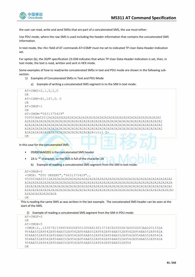
M5311 AT Command Specification
91 /192
the user can read, write and send SMSs that are part of a concatenated SMS, the use must either:
Use PDU mode, where the raw SMS is used including the header information that contains the concatenated SMS information.
In text mode, the <fo> field of AT commands AT+CSMP must me set to indicated TP-User-Data-Header-Indication set.
For option (b), the 3GPP specification 23.038 indicates that when TP-User-Data-Header-Indication is set, then, in text mode, the text is read, written and sent in HEX mode.
Some examples of how to read/write concatenated SMSs in text and PDU mode are shown in the following sub- section.
1) Examples of Concatenated SMSs in Text and PDU Mode
a) Example of writing a concatenated SMS segment in to the SIM in text mode:
AT+CNMI=2,1,0,2,0
OK
AT+CSMP=81,167,0,0
OK
AT+CMGF=1
OK
AT+CMGW="0631375429"
050003AA02012A2A2A2A2A2A2A2A2A2A2A2A2A2A2A2A2A2A2A2A2A2A2A2A2A2A2A2A2A2A2
A2A2A2A2A2A2A2A2A2A2A2A2A2A2A2A2A2A2A2A2A2A2A2A2A2A2A2A2A2A2A2A2A2A2A2
A2A2A2A2A2A2A2A2A2A2A2A2A2A2A2A2A2A2A2A2A2A2A2A2A2A2A2A2A2A2A2A2A2A2A2
A2A2A2A2A2A2A2A2A2A2A2A2A2A2A2A2A2A2A2A2A2A2A2A2A2A2A2A2A2A2A2A2A2A2A2
A2A2A2A2A2A2A2A2A2A2A2A2A2A2A2A2A2A<ctrl Z>
OK
In this case for the concatenated SMS:
050003AA0201 is the concatenated SMS header
2A is ‘*’ character, so the SMS is full of the character 2A
b) Example of reading a concatenated SMS segment from the SIM in text mode:
AT+CMGR=5
+CMGR: "STO UNSENT","0631375429",,
050003AA02012A2A2A2A2A2A2A2A2A2A2A2A2A2A2A2A2A2A2A2A2A2A2A2A2A2A2A2A2A2A2A2
A2A2A2A2A2A2A2A2A2A2A2A2A2A2A2A2A2A2A2A2A2A2A2A2A2A2A2A2A2A2A2A2A2A2A2A2A2A
2A2A2A2A2A2A2A2A2A2A2A2A2A2A2A2A2A2A2A2A2A2A2A2A2A2A2A2A2A2A2A2A2A2A2A2A2A2
A2A2A2A2A2A2A2A2A2A2A2A2A2A2A2A2A2A2A2A2A2A2A2A2A2A2A2A2A2A2A2A2A2A2A2A2A2A2
A2A2A2A2A2A2A2A2A
OK
This is reading the same SMS as was written in the last example. The concatenated SMS header can be seen at the start of the SMS.
2) Example of reading a concatenated SMS segment from the SIM in PDU mode: AT+CMGF=0
OK
AT+CMGR=5
+CMGR:2,,15307913386094000F051000A8160137345920000A7A0050003AA0201552A
954AA552A9542A954AA552A9542A954AA552A9542A954AA552A9542A954AA552A9542A
954AA552A9542A954AA552A9542A954AA552A9542A954AA552A9542A954AA552A9542A
954AA552A9542A954AA552A9542A954AA552A9542A954AA552A9542A954AA552A9542A
954AA552A9542A954AA552A9542A954AA552A9542A954AA552A954
OK

M5311 AT Command Specification
92 /192
In this example:
07913386094000F051000A8160137345920000A7A0 is the SMS header
050003AA0201 still is the SMS concatenated header
all the remaining characters are the ‘*’ character (7-bits default alphabet) encoded into 8-bits bytes.
3.4.3. Detailed Descriptions of Commands
3.4.3.1. AT+CMGD
AT+CMGD Delete SMS message
Test command
AT+CMGD=?
Response
• +CMGD: list of supported <index>s
• OK
Execute command
AT+CMGD=<index>[,<DelFlag>]
Response
TA deletes one or several messages from preferred message storage <mem1> location <index> or message groups indicated by <DelFlag>.
OK
If error is related to ME functionality:
o +CMS ERROR <err>
Parameters
• <index> integer type; value in the range of location numbers supported by the associated memory. This value is only used if <DelFlag> = 0
• <DelFlag> message delete mode
0 Delete message at location <index> (Default value)
1 Delete all read messages
2 Delete all READ and SENT messages
3 Delete all READ, SENT and UNSENT messages
4 Delete all messages
Scope o Channel Specific for test command
o Generic for execute command
Reference 3GPP TS
27.005
Note
When the M5311 software has concatenated SMS handling in modem enabled (see AT command AT*MFTRCFG) the user can delete a concatenated text SMS up to 1024 characters in length. A concatenated SMS is stored on the SIM as number of smaller SMSs. (This is not possible when MMI is present).
When the M5311 software does not have concatenated SMS handling in the modem enabled, the maximum text SMS length is restricted depending on the data coding scheme (160 for 7-bit, 140 for 8-bit, 80 for 16-bit).
An attempt to delete anything other than the first segment of a concatenated SMS, when concat SMS is enabled, will result in ERROR response.
Deleting an empty entry will result in OK response rather than ERROR.

M5311 AT Command Specification
93 /192
3.4.3.2. AT+CMGF
AT+CMGF Select SMS Message Format
Test command
AT+CMGF=?
Response
• +CMGF: list of supported <mode>s
• OK
Read command
AT+CMGF?
Response
• +CMGF: <mode>
• OK
Set command
AT+CMGF=[<mode>]
Response
• TA sets parameter to denote which input and output format of messages to use.
• OK
Parameters
<mode>
0 PDU mode
1 text mode
Scope Channel Specific
Reference 3GPP TS
27.005 Note
3.4.3.3. AT+CMGL
AT+CMGL List SMS messages from preferred store
Test command
AT+CMGL=?
Response
• +CMGL: list of supported <stat>s
• OK
Execute command
AT+CMGL[=<stat>]
Response
TA returns messages with status value <stat> from message storage <mem1> to the TE. . If status of the message is 'received unread', status in the storage changes to 'received read'.
• If text mode (+CMGF=1) and command
successful: for SMS-SUBMITs and/or SMS-DELIVERs:
o +CMGL: <index>,<stat>,<oa/da>,[<alpha>],[<scts>][,<tooa/toda>,<length>]<CR><LF><data>[<CR><LF>
o +CMGL: <index>,<stat>,<da/oa>,[<alpha>],[<scts>][,<tooa/toda>,<length>]<CR><LF><data>[...]] OK
• If SMS-STATUS-REPORT and text mode:
o +CMGL: <index>,<stat>,<fo>,<mr>,[<ra>],[<tora>],<scts>,<dt>,<st>
o [<CR><LF>

M5311 AT Command Specification
94 /192
o +CMGL: <index>,<stat>,<fo>,<mr>,[<ra>],[<tora>],<scts>,<dt>,<st> [...]] OK
• If PDU
mode (+CMGF=0) and command successful:
o +CMGL: <index>,<stat>,[<alpha>],<length><CR><LF><pdu>
o [<CR><LF>+CMGL: <index>,<stat>,[alpha],<length><CR><LF><pdu>
o [...]]
o OK
• If error is related to ME functionality:
o +CMS ERROR: <err>
Parameters
• <alpha> string type alphanumeric representation of <da> or <oa> corresponding to the entry found in MT phonebook; implementation of this feature is manufacturer specific
• <da> 3GPP 23.040 TP-Destination-Address Address-Value field in string format; BCD numbers (or GSM default alphabet characters) are converted to characters; type of address given by <toda>
• <data> In the case of SMS: 3GPP 23.040 TP-User-Data in text mode responses; format:
o if <dcs> indicates that 3GPP 23.038 default alphabet is used and <fo> indicates that 3GPP 23.040 TP-User-Data-Header-Indication is not set: ME/TA converts GSM alphabet into current TE character set according to rules of Annex A
o if <dcs> indicates that 8-bit or UCS2 data coding scheme is used, or <fo> indicates that 3GPP 23.040 TP-User-Data-Header-Indication is set: ME/TA converts each 8-bit octet into two IRA character long hexadecimal number (e.g. octet with integer value 42 is presented to TE as two characters 2A (IRA 50 and 65))
In the case of CBS: 3GPP 23.041 CBM Content of Message in text mode responses; format:
o if <dcs> indicates that 3GPP 23.038 default alphabet is used:ME/TA converts GSM alphabet into current TE character set according to rules of Annex A
o if <dcs> indicates that 8-bit or UCS2 data coding scheme is used: ME/TA converts each 8-bit octet into two IRA character long hexadecimal number
• <length> integer type value indicating in the text mode (+CMGF=1) the length of the
message body <data> (or <cdata>) in characters; or in PDU mode (+CMGF=0), the length of the actual TP data unit in octets (i.e. the RP layer SMSC address octets are not counted in the length)
• <index> integer type; value in the range of location numbers supported by the associated memory
• <oa> 3GPP 23.040 TP-Originating-Address Address-Value field in string format; BCD numbers (or GSM default alphabet characters) are converted to characters; type of address given by <tooa>
• <pdu> In the case of SMS: 3GPP 24.011 SC address followed by 3GPP 23.040 TPDU in hexadecimal format: ME/TA converts each octet of TP data unit into two IRA character long hexadecimal number (e.g. octet with integer value 42 is presented to TE as two characters 2A (IRA 50 and 65)). In the case of CBS: 3GPP 23.041 TPDU in hexadecimal format.
• <scts> 3GPP 23.040 TP-Service-Center-Time-Stamp in time-string format (refer <dt>)

M5311 AT Command Specification
95 /192
• <toda> 3GPP 24.011 TP-Destination-Address Type-of-Address octet in integer format (when first character of <da> is + (IRA 43) default is 145, otherwise default is 129)
• <tooa> 3GPP 24.011 TP-Originating-Address Type-of-Address octet in integer format (default refer<toda>)
• <fo> First byte of SMS-DELIVER, SMS-SUBMIT or SMS-STATUS-REPORT in integer format.
<mr> Message reference. Integer format.
<ra> Recipient address. String type.
<tora> Type of address of <ra>.
o 145: International number
o 129: National number
• <scts> Service centre time stamp. String format: “yy/MM/dd,hh:mm:ss+/-zz” (Year/Month/Dat,Hour:Seconds+/TimeZone)
• <dt> Discharge time. String format: “yy/MM/dd,hh:mm:ss+/-zz”(Year/Month/Dat,Hour:Seconds+/TimeZone)
• <st> Status of an SMS-STATUS-REPORT. Integer format.
Parameters
• If text mode:
<stat> "REC UNREAD" Received unread messages (default)
"REC READ" Received read messages
"STO UNSENT" Stored unsent messages
"STO SENT" Stored sent messages
"ALL" All messages
• If PDU mode:
<stat> 0 Received unread messages (default)
1 Received read messages
2 Stored unsent messages
3 Stored sent messages
4 All messages
Scope Channel Specific (reads from generic SMS store)
Reference 3GPP TS
27.005
Note
• Read of SMS-SRs when <mem1> is set to “SR” can read SIM memory
• When the M5311 software has concatenated SMS handling in modem enabled (see AT command AT*MFTRCFG) the user can read a concatenated text SMS up to 1024 characters in length. A concatenated SMS is stored on the SIM as number of smaller SMSs. (This is not possible when MMI is present).
• When the M5311 software does not have concatenated SMS handling in the modem enabled, the maximum text SMS length is restricted depending on the data coding scheme (160 for 7-bit, 140 for 8-bit, 80 for 16-bit).
3.4.3.4. AT+CMGR
AT+CMGR Read SMS message
Test command
AT+CMGR=?
Response
• OK
Execute command
AT+CMGR=<index>
Response
TA returns SMS message with location value <index> from message storage <mem1> to the

M5311 AT Command Specification
96 /192
TE. If status of the message is 'received unread', status in the storage changes to 'received read'.
• If text mode (+CMGF=1) and command successful:
o for SMS-DELIVER:
+CMGR:<stat>,<oa>,[<alpha>],<scts>[,<tooa>,<fo>,<pid>,<dcs>,
<sca>,<tosca>,<length>]<CR><LF><data> OK
o for SMS-SUBMIT:
+CMGR:<stat>,<da>,[<alpha>][,<toda>,<fo>,<pid>,<dcs>,[<vp>],<sca>,<tosca>,<length>]<CR><LF><data>
OK
• If SMS-STATUS-REPORT and text mode:
+CMGR: <stat>,<fo>,<mr>,[<ra>],[<tora>],<scts>,<dt>,<st>
OK
• If PDU mode (+CMGF=0) and command successful:
+CMGR: <stat>,[<alpha>],<length><CR><LF><pdu>
OK
• If error is related to ME functionality:
+CMS ERROR: <err>
Parameters
• <index> integer type; value in the range of location numbers supported by the associated memory
• <alpha> string type alphanumeric representation of <da> or <oa> corresponding to the entry found in MT phonebook; implementation of this feature is manufacturer specific.
• <da> 3GPP 23.040 TP-Destination-Address Address-Value field in string format; BCD numbers (or GSM default alphabet characters) are converted to characters of the currently selected TE character set (specified by +CSCS); type of address given by <toda>
• <data> In the case of SMS: 3GPP 23.040 TP-User-Data in text mode responses; format:
o if <dcs> indicates that 3GPP 23.038 default alphabet is used and <fo> indicates that 3GPP 23.040 TP-User-Data-Header-Indication is not set:
ME/TA converts GSM alphabet into current TE character set according to rules of Annex A
o if <dcs> indicates that 8-bit or UCS2 data coding scheme is used, or <fo> indicates that 3GPP 23.040 TP-User-Data-Header-Indication is set: ME/TA converts each 8- bit octet into two IRA character long hexadecimal number (e.g. octet with integer value 42 is presented to TE as two characters 2A (IRA 50 and 65)).
In the case of CBS: 3GPP 23.041 CBM Content of Message in text mode responses;
format:
o if <dcs> indicates that 3GPP 23.038 default alphabet is used:
ME/TA converts GSM alphabet into current TE character set according to rules of Annex A
o if <dcs> indicates that 8-bit or UCS2 data coding scheme is used: ME/TA converts
each 8-bit octet into two IRA character long hexadecimal number
• <dcs> depending on the command or result code: 3GPP 23.038 SMS Data Coding Scheme (default 0), or Cell Broadcast Data Coding Scheme in integer format
• <fo> depending on the command or result code: first octet of 3GPP 23.040 SMS-DELIVER, SMS-SUBMIT (default 17), SMS-STATUS-REPORT, orSMS-COMMAND (default 2) in integer format

M5311 AT Command Specification
97 /192
• <length> integer type value indicating in the text mode (+CMGF=1) the length of the message body <data> (or <cdata>) in characters; or in PDU mode (+CMGF=0), the length of the actual TP data unit in octets (i.e. the RP layer SMSC address octets are not counted in the length)
• <mid> 3GPP 23.041 CBM Message Identifier in integer format
• <oa> 3GPP 23.040 TP-Originating-Address Address-Value field in string format; BCD numbers (or GSM default alphabet characters) are converted characters of the currently selected TE character set (specified by +CSCS);; type of address given by <tooa>
• <pdu> In the case of SMS: 3GPP 24.011 SC address followed by 3GPP 23.040 TPDU in hexadecimal format: ME/TA converts each octet of TP data unit into two IRA character long hexadecimal number (e.g. octet with integer value 42 is presented to TE as two characters 2A (IRA 50 and 65)). In the case of CBS: 3GPP 23.041 TPDU in hexadecimal format.
• <sca> SGPP 24.011 RP SC address Address-Value field in string format; BCD numbers (or GSM default alphabet characters) are converted to characters of the currently selected TE character set (specified by +CSCS);; type of address given by <tosca>
• <scts> 3GPP 23.040 TP-Service-Centre-Time-Stamp in time-string format (refer <dt>)
• <stat>
0 "REC UNREAD" Received unread messages
1 "REC READ" Received read messages
2 "STO UNSENT" Stored unsent messages
3 "STO SENT" Stored sent messages
4 "ALL" All messages
• <toda> 3GPP 24.011 TP-Destination-Address Type-of-Address octet in integer format (when first character of <da> is + (IRA 43) default is 145, otherwise default is 129)
• <tooa> 3GPP 24.011 TP-Originating-Address Type-of-Address octet in integer format (default refer<toda>)
• <tosca> 3GPP 24.011 RP SC address Type-of-Address octet in integer format (default refer <toda>)
• <vp> depending on SMS-SUBMIT <fo> setting: 3GPP 23.040 TP-Validity-Period either in integer format (default 167) or in time-string format (refer <dt>)
• <mr> Message reference. Integer format.
• <ra> Recipient address. String type.
• <tora> Type of address of <ra>.
o 145: International number
o 129: National number
• <dt> Discharge time. String format: “yy/MM/dd,hh:mm:ss+/-zz” (Year/Month/Dat,Hour:Seconds+/TimeZone)
• <st> Status of an SMS-STATUS-REPORT. Integer format.
Scope Channel Specific (reads from generic SMS store)
Reference 3GPP TS
27.005
Note
• Read of SMS-SRs when <mem1> is set to “SR” can read SIM memory
• When the M5311 software has concatenated SMS handling in modem enabled (see AT command AT*MFTRCFG) the user can read a concatenated text SMS up to 1024 characters in length. A concatenated SMS is stored on the SIM as number of smaller SMSs. (This is not possible when MMI is present).

M5311 AT Command Specification
98 /192
• When the M5311 software does not have concatenated SMS handling in the modem enabled, the maximum text SMS length is restricted depending on the data coding scheme (160 for 7-bit, 140 for 8-bit, 80 for 16-bit).
3.4.3.5. AT+CMGS
AT+CMGS Send SMS message
Test command
AT+CMGS=?
Response
• OK
Execute command
1) If text mode
(+CMGF=1):
AT+CMGS=<da>[,<toda>]<CR>
text is entered<ctrl-Z/ESC> ESC quits without sending
2) If PDU mode (+CMGF=0):
AT+CMGS=<leng th><CR>
PDU is given
<ctrl-Z/ESC>
Response
TA transmits SMS message from a TE to the network (SMS-SUBMIT). Message reference value <mr> is returned to the TE on successful message delivery. Value can be used to identify message upon unsolicited delivery status report result code.
• If text mode(+CMGF=1) and sending successful:
o +CMGS: <mr> OK
• If PDU mode(+CMGF=0) and sending successful:
o +CMGS: <mr> OK
• If error is related to ME functionality:
o +CMS ERROR: <err>
Parameters
Parameters
• <da> 3GPP 23.040 TP-Destination-Address Address-Value field in string format; BCD numbers (or GSM default alphabet characters) are converted to characters of the currently selected TE character set (specified by +CSCS); type of address given by <toda>
• <toda> 3GPP 24.011 TP-Destination-Address Type-of-Address octet in integer format (when first character of <da> is + (IRA 43) default is 145, otherwise default is 129)
• <length> integer type value indicating in the text mode (+CMGF=1) the length of the message body <data> (or <cdata>) in characters; or in PDU mode (+CMGF=0), the length of the actual TP data unit in octets (i.e. the RP layer SMSC address octets are not counted in the length)
• <mr> 3GPP 23.040 TP-Message-Reference in integer format
Scope o Channel Specific for test command
o Generic for execute command
Reference 3GPP TS
27.005
Note
• When the M5311 software has concatenated SMS handling in modem enabled (see

M5311 AT Command Specification
99 /192
AT command AT*MFTRCFG) the user can send a text SMS up to 1024 characters in length. A concatenated SMS is sent to the network in a number of smaller SMSs. (This is not possible when MMI is present).
• When the M5311 software does not have concatenated SMS handling in the modem enabled, the maximum text SMS length is restricted depending on the data coding scheme (160 for 7-bit, 140 for 8-bit, 80 for 16-bit).
3.4.3.6. AT+CMGW
AT+CMGW Write SMS message to memory
Test command
AT+CMGW=?
Response
• OK
1) If text mode (+CMGF=1): AT+CMGW[=<oa/da>[,<tooa/toda>[,<stat>[,<scts>]]]]<CR> text is entered
<ctrl-Z/ESC>
<ESC> quits without sending
2) If PDU mode (+CMGF=0):
AT+CMGW=<leng th>[,<stat>]<CR>
PDU is given
<ctrl-Z/ESC>
Execute command
Response
TA transmits SMS message (either SMS-DELIVER or SMS-SUBMIT) from TE to memory storage <mem2>. Memory location <index> of the stored message is returned. By default message status will be set to 'stored unsent', but parameter <stat> allows also other status values to be given.
• If writing is successful:
o +CMGW: <index> OK
• If error is related to ME functionality:
o +CMS ERROR: <err>
•
Parameters
• <oa> 3GPP 23.040 TP-Originating-Address Address-Value field in string format; BCD numbers (or GSM default alphabet characters) are converted to characters of the currently selected TE character set (specified by +CSCS);; type of address given by <tooa>
• <da> 3GPP 23.040 TP-Destination-Address Address-Value field in string format; BCD numbers (or GSM default alphabet characters) are converted to characters of the currently selected TE character set (specified by +CSCS);; type of address given by <toda>
• <tooa> 3GPP 24.011 TP-Originating-Address Type-of-Address octet in integer format (default refer <toda>)
• <toda> 3GPP 24.011 TP-Destination-Address Type-of-Address octet in integer format (when first character of <da> is + (IRA 43) default is 145, otherwise default is 129)
• <length> integer type value indicating in the text mode (+CMGF=1) the length of the message body <data> (or <cdata>) in characters; or in PDU

M5311 AT Command Specification
100 /192
mode (+CMGF=0), the length of the actual TP data unit in octets (i.e. the RP layer SMSC address octets are not counted in the length)
• <pdu> In the case of SMS: 3GPP 24.011 SC address followed by 3GPP 23.040 TPDU in hexadecimal format: ME/TA converts each octet of TP data unit into two IRA character long hexadecimal number (e.g. octet with integer value 42 is presented to TE as two characters 2A (IRA 50 and 65)). In the case of CBS: 3GPP 23.041 TPDU in hexadecimal format.
• <index> Index of message in selected storage <mem2>
• <stat> Status of message when stored in memory
0 "REC UNREAD" Received unread message
1 "REC READ" Received read message
2 "STO UNSENT" Stored unsent message (default)
3 "STO SENT" Stored sent message
• <scts> 3GPP 23.040 TP-Service-Centre-Time-Stamp in time- string format String format: “yy/MM/dd,hh:mm:ss+/-zz” (Year/Month/Day,Hour:Seconds+/TimeZone). Field only required when writing SMS-DELIVER.
Scope o Channel Specific for test command
o Generic for execute command
Reference 3GPP TS
27.005
Note
• When the M5311 software has concatenated SMS handling in modem enabled (see AT command AT*MFTRCFG) the user can write a text SMS up to 1024 characters in length. A concatenated SMS is stored on the SIM as number of smaller SMSs. (This is not possible when MMI is present).
• When the M5311 software does not have concatenated SMS handling in the modem enabled, the maximum text SMS length is restricted depending on the data coding scheme (160 for 7-bit, 140 for 8-bit, 80 for 16-bit).
3.4.3.7. AT+CMSS
AT+CMSS Send SMS message from storage
Test command
AT+CMSS=?
Response
• OK
Execute command
AT+CMSS=<index>[,<da>[,<toda>]]
Response
TA sends message with location value <index> from message storage <mem2> to the network (SMS-SUBMIT). If new recipient address <da> is given, it shall be used instead of the one stored with the message. Reference value <mr> is returned to the TE on successful message delivery. Values can be used to identify message upon unsolicited delivery status report result code.
• If text mode(+CMGF=1) and sending successful:
o +CMSS: <mr> OK
• If PDU mode(+CMGF=0) and sending successful:
o +CMSS: <mr> OK
• If error is related to ME functionality:
o +CMS ERROR: <err>
Parameters • <index> integer type; value in the range of location numbers supported by the associated memory

M5311 AT Command Specification
101 /192
• <da> 3GPP 23.040 TP-Destination-Address Address-Value field in string format; BCD numbers (or GSM default alphabet characters) are converted to characters of the currently selected TE character set (specified by +CSCS); type of address given by <toda>
• <toda> 3GPP 24.011 TP-Destination-Address Type-of-Address octet in integer format (when first character of <da> is + (IRA 43) default is 145, otherwise default is 129)
• <mr> 3GPP 23.040 TP-Message-Reference in integer format
Scope o Channel Specific for test command
o Generic for execute command
Reference 3GPP TS
27.005
Note
When the M5311 software has concatenated SMS handling in modem enabled (see AT command AT*MFTRCFG) this command will send the all stored messages which form part of a concatenated SMS. (This is not possible when the MMI is present).
3.4.3.8. AT+CMGC
AT+CMGC Send SMS Command
Test command
AT+CMGC=?
Response
• OK
Execute command
1) If text mode(+CMGF=1):
AT+CMGC=<fo>,<ct>[<pi d>[,<mn>[,<da>[,<toda>]]]]<CR>
text is entered
<ctrl-Z/ESC> ESC quits without sending
2) If PDU mode (+CMGF=0):
AT+CMGC=<length><CR>
PDU is given
<ctrl-Z/ESC>
Response
TA transmits SMS Command message from a TE to the network (SMS-COMMAND). Message reference value <mr> is returned to the TE on successful message delivery. Value can be used to identify message upon unsolicited delivery status report result code.
• If text mode (+CMGF=1) and sending successful:
o +CMGC: <mr> OK
• If PDU mode (+CMGF=0) and sending successful:
o +CMGC: <mr> OK
• If error is related to ME functionality:
o +CMS ERROR: <err>
Parameters
• <fo> first octet of 3GPP 23.040 SMS-COMMAND (default 2) in integer format
• <ct> 3GPP 23.040 TP-Command-Type in integer format (default 0)
• <pid> 3GPP 23.040 TP-Protocol-Identifier in integer format (default 0)
• <mn> 3GPP 23.040 TP-Message-Number in integer format
• <da> 3GPP 23.040 TP-Destination-Address Address-Value field in string format; BCD numbers (or GSM default alphabet characters) are

M5311 AT Command Specification
102 /192
converted to characters of the currently selected TE character set (specified by +CSCS);; type of address given by <toda>
• <toda> 3GPP 24.011 TP-Destination-Address Type-of-Address octet in integer format (when first character of <da> is + (IRA 43) default is 145, otherwise default is 129)
• <length> integer type value indicating in PDU mode (+CMGF=0), the length of the actual TP data unit in octets (i.e. the RP layer SMSC address octets are not counted in the length)
• <mr> 3GPP 23.040 TP-Message-Reference in integer format
Scope o Channel Specific for test command
o Generic for execute command
Reference 3GPP TS
27.005 Note
3.4.3.9. AT+CNMI
AT+CNMI New SMS message indications
Test command
AT+CNMI=?
Response
• +CNMI: (list of supported <mode>s),(list of supported <mt>s),(list of supported <bm>s),(list of supported <ds>s),(list of supported <bfr>s)
• OK
Read command
AT+CNMI?
Response
• +CNMI: <mode>,<mt>,<bm>,<ds>,<bfr>
• OK
Set command
AT+CNMI =[<mode> [,<mt>[,<bm> [,<ds>[,<bfr>]]]]]
Response
• TA selects the procedure for how the receiving of new messages from the network is indicated to the TE when TE is active, e.g. DTR signal is ON. If TE is inactive (e.g. DTR signal is OFF), message receiving should be done as specified in 3GPP 23.038.
• OK
• If error is related to ME functionality:
o +CMS ERROR: <err>
Parameters
• <mode>
0 Buffer unsolicited result codes in the TA. If TA result code buffer is full, indications can be buffered in some other place or the oldest indications may be discarded and replaced with the new received indications.
1 Discard indication and reject new received message unsolicited result codes when TA-TE link is reserved (e.g. in on-line data mode). Otherwise forward them directly to the TE.
2 Buffer unsolicited result codes in the TA when TA-TE link is reserved (e.g. in on-line data mode) and flush them to the TE after reservation. Otherwise forward them directly to the TE.
3 Forward unsolicited result codes directly to the TE. TA-TE link specific inband technique used to embed result codes and data when TA is in on-line data mode.
• <mt> (the rules for storing received SMs depend on its data coding scheme
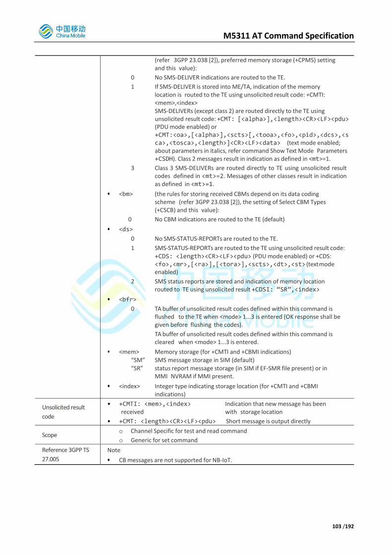
M5311 AT Command Specification
103 /192
(refer 3GPP 23.038 [2]), preferred memory storage (+CPMS) setting and this value):
0 No SMS-DELIVER indications are routed to the TE.
1 If SMS-DELIVER is stored into ME/TA, indication of the memory location is routed to the TE using unsolicited result code: +CMTI: <mem>,<index> SMS-DELIVERs (except class 2) are routed directly to the TE using unsolicited result code: +CMT: [<alpha>],<length><CR><LF><pdu> (PDU mode enabled) or +CMT:<oa>,[<alpha>],<scts>[,<tooa>,<fo>,<pid>,<dcs>,<sca>,<tosca>,<length>]<CR><LF><data> (text mode enabled; about parameters in italics, refer command Show Text Mode Parameters +CSDH). Class 2 messages result in indication as defined in <mt>=1.
3 Class 3 SMS-DELIVERs are routed directly to TE using unsolicited result codes defined in <mt>=2. Messages of other classes result in indication as defined in <mt>=1.
• <bm> (the rules for storing received CBMs depend on its data coding scheme (refer 3GPP 23.038 [2]), the setting of Select CBM Types (+CSCB) and this value):
0 No CBM indications are routed to the TE (default)
• <ds>
0 No SMS-STATUS-REPORTs are routed to the TE.
1 SMS-STATUS-REPORTs are routed to the TE using unsolicited result code:
+CDS: <length><CR><LF><pdu> (PDU mode enabled) or +CDS: <fo>,<mr>,[<ra>],[<tora>],<scts>,<dt>,<st> (text mode enabled)
2 SMS status reports are stored and indication of memory location routed to TE using unsolicited result +CDSI: “SR”,<index>
• <bfr>
0 TA buffer of unsolicited result codes defined within this command is flushed to the TE when <mode> 1...3 is entered (OK response shall be given before flushing the codes).
TA buffer of unsolicited result codes defined within this command is cleared when <mode> 1...3 is entered.
• <mem> Memory storage (for +CMTI and +CBMI indications)
“SM” SMS message storage in SIM (default)
“SR” status report message storage (in SIM if EF-SMR file present) or in MMI NVRAM if MMI present.
• <index> Integer type indicating storage location (for +CMTI and +CBMI indications)
Unsolicited result
code
• +CMTI: <mem>,<index> Indication that new message has been received with storage location
• +CMT: <length><CR><LF><pdu> Short message is output directly
Scope o Channel Specific for test and read command
o Generic for set command
Reference 3GPP TS
27.005
Note
• CB messages are not supported for NB-IoT.

M5311 AT Command Specification
104 /192
3.4.3.10. AT+CPMS
AT+CPMS Preferred SMS Message Storage
Test command
AT+CPMS=?
Response
• +CPMS: (list of supported <mem1>s),(list of supported <mem2>s) ,(list of supported
<mem3>s)
• OK
Read command
AT+CPMS?
Response
• +CPMS: <mem1>,<used1>,<total1>,<mem2>,<used2>,<total2>,
<mem3>,<used3>,<total3>
• OK
• If error is related to ME functionality:
o +CMS ERROR
Set command
AT+CPMS =<mem1> [,<mem2> [,<mem3>]]
Response
• TA selects memory storages <mem1>, <mem2> and <mem3> to be used for reading, writing, etc.
• +CPMS: <used1>,<total1>,<used2>,<total2>,<used3>,<total3>
• OK
• If error is related to ME functionality:
o +CMS ERROR:<err>
•
Parameters
• <mem1> Messages to be read and deleted from this memory storage
"SM" SIM message storage “SR” Status Report message storage (EF-SMR if available on SIM).
SR in SIM are only associated with SMSs stored on SIM.
If EF-SMR not available and MMI is present then status reports are stored in NVRAM. In addition MMI can store status reports in NVRAM as well as ones stored on SIM (EF-SMR file), if available.
• <mem2> Messages will be written and sent to this memory storage
"SM" SIM message storage
• <mem3> Received messages will be placed in this memory storage if routing to PC is not set ("+CNMI")
"SM" SIM message storage
• <usedx> Number of messages currently in <memx>
• <totalx> Number of messages storable in <memx>
Scope o Channel Specific for test and read command
o Generic for set command
Reference 3GPP TS
27.005 Note
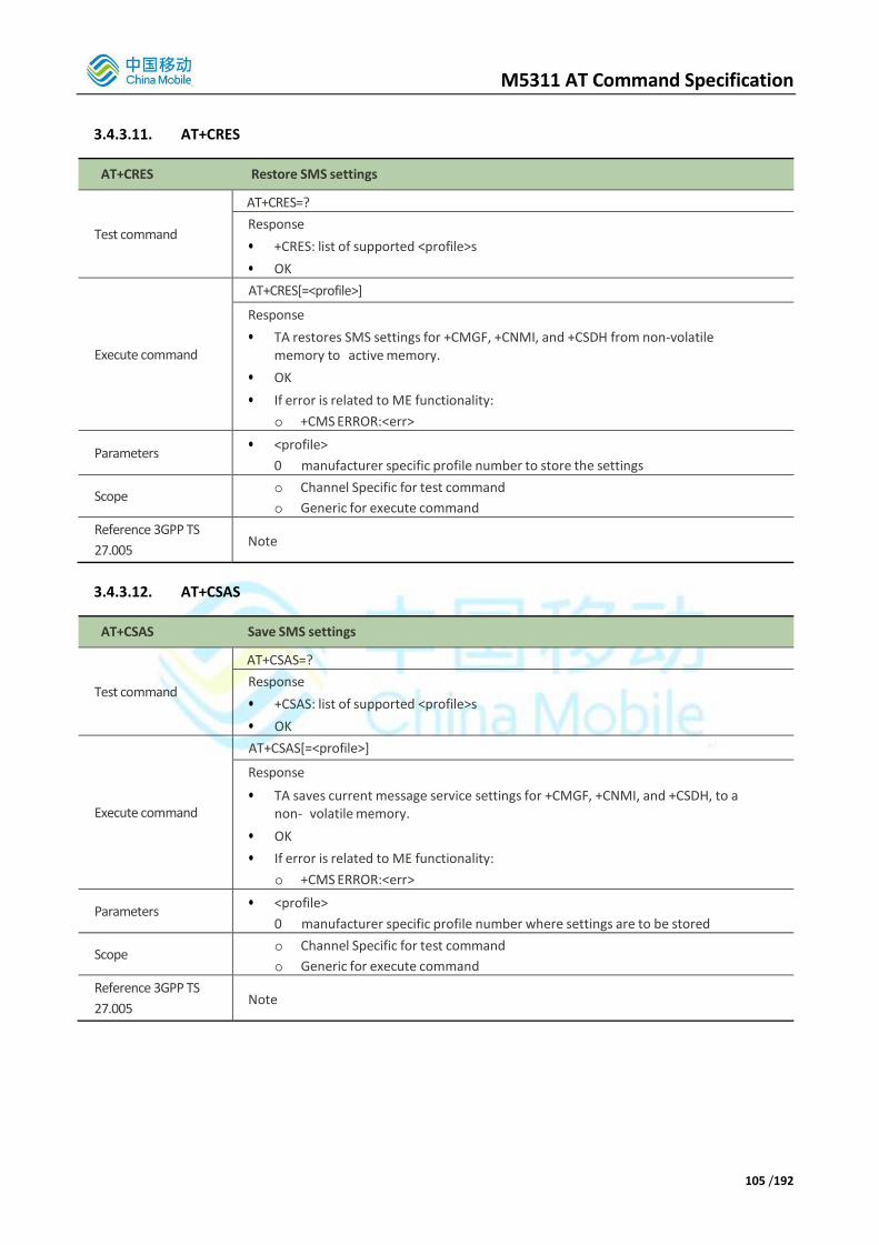
M5311 AT Command Specification
105 /192
3.4.3.11. AT+CRES
AT+CRES Restore SMS settings
Test command
AT+CRES=?
Response
• +CRES: list of supported <profile>s
• OK
Execute command
AT+CRES[=<profile>]
Response
• TA restores SMS settings for +CMGF, +CNMI, and +CSDH from non-volatile memory to active memory.
• OK
• If error is related to ME functionality:
o +CMS ERROR:<err>
Parameters • <profile>
0 manufacturer specific profile number to store the settings
Scope o Channel Specific for test command
o Generic for execute command
Reference 3GPP TS
27.005 Note
3.4.3.12. AT+CSAS
AT+CSAS Save SMS settings
Test command
AT+CSAS=?
Response
• +CSAS: list of supported <profile>s
• OK
Execute command
AT+CSAS[=<profile>]
Response
• TA saves current message service settings for +CMGF, +CNMI, and +CSDH, to a non- volatile memory.
• OK
• If error is related to ME functionality:
o +CMS ERROR:<err>
Parameters • <profile>
0 manufacturer specific profile number where settings are to be stored
Scope o Channel Specific for test command
o Generic for execute command
Reference 3GPP TS
27.005 Note

M5311 AT Command Specification
106 /192
3.4.3.13. AT+CSCA
AT+CSAS Save SMS settings
Test command
AT+CSCA=?
Response
• OK
Read command
AT+CSCA?
Response
• +CSCA: <sca>,<tosca>
• OK
Set command
AT+CSCA =<sca>[,<tosca>]
Response
• TA updates the SMSC address, through which mobile originated SMs are transmitted. In text mode, setting is used by send and write commands. In PDU mode, setting is used by the same commands, but only when the length of the SMSC address coded into <pdu> parameter equals zero.
• Note: The command writes the parameters in NON-VOLATILE memory.
• OK
Parameters
• <sca> 3GPP 24.011 RP SC address Address-Value field in string format; BCD numbers (or GSM default alphabet characters) are converted to characters of the currently selected TE character set (specified by +CSCS); type of address given by <tosca>
• <tosca> Service center address format 3GPP 24.011 RP SC address Type-of-Address octet in integer format (default refer <toda>)
Scope o Channel Specific for test and read command
o Generic for set command
Reference 3GPP TS
27.005 Note
3.4.3.14. AT+CSDH
AT+CSDH Show SMS text mode parameters
Test command
AT+CSDH=?
Response
• +CSDH: list of supported <show>s
• OK
Read command
AT+CSDH?
Response
• +CSDH:<show>
• OK
Set command
AT+CSDH=<show>
Response
• TA determines whether detailed header information is shown in text mode result codes.
• OK
Parameters • <show>
0 do not show header values defined in commands +CSCA and

M5311 AT Command Specification
107 /192
+CSMP (<sca>, <tosca>, <fo>, <vp>, <pid> and <dcs>) nor <length>, <toda> or <tooa> in +CMT, +CMGL, +CMGR result codes in text mode
1 show the values in result codes
Scope o Channel Specific
Reference 3GPP TS
27.005 Note
3.4.3.15. AT+CSMP
AT+CSMP Set SMS text mode parameters
Test command
AT+CSMP=?
Response
• OK
Read command
AT+CSMP?
Response
• +CSMP:<fo>,<vp>,<pid>,<dcs>
• OK
Set command
AT+CSMP=[<fo> [<vp>[,<pid>[,<dcs>]]]]
Response
• TA selects values for additional parameters needed when SM is sent to the network or placed in storage when text mode is selected (+CMGF=1). It is possible to set the validity period starting from when the SM is received by the SMSC (<vp> is in range 0... 255).
• OK
Parameters
• <fo> first octet of 3GPP 23.040 SMS-DELIVER, SMS-SUBMIT in integer format. The following fields can be modified:
o TP-Message-Type-Indicator (bits 0-1) (SMS-DELIVER or SMS-
o SUBMIT)
o TP-Reject-Duplicates (bit 2)
o TP-Validity-Period-Format (bits 3-4)
o TP-Status-Report-Request (bit 5)
o TP-User-Data-Header-Indicator (bit 6)
o TP-Reply-Path (bit 7). Default value is 17 (SMS-SUBMIT and Validity Period in relative format)
When concatenated SMS is supported by M5311, attempts to change the following fields from the default will produce an ERROR:
TP-User-Data-Header-Indicator (bit 6) – the UDHI field is used for concatenated SMSs and is set by the Background Layer where appropriate.
• <vp> 3GPP 23.040 TP-Validity-Period in integer format (default 167).
• <pid> 3GPP 23.040 TP-Protocol-Identifier in integer format (default 0)
• <dcs> 3GPP 23.038 SMS Data Coding Scheme in Integer format (default 0 i.e. 7-bit coding).
Scope o Channel Specific for test and read command
o Generic for set command
Reference 3GPP TS
27.005
Note
The command writes the settings <vp>, <pid> and <dcs> in SIM memory. <fo> field is not stored anywhere.

M5311 AT Command Specification
108 /192
On startup, the settings <vp>, <pid> and <dcs> are read from the SIM and used for SMS AT commands. If they cannot be found in the SIM they are set to the default values.
The <fo> field is always set to the default value at startup.
3.4.3.16. AT+CSMS
AT+CSMS Select Message Service
Test command
AT+CSMS=?
Response
• +CSMS: list of supported <service>s
• OK
Read command
AT+CSMS?
Response
• +CSMS: <service>,<mt>,<mo>,<bm>
• OK
Set command
AT+CSMS=<service>
Response
• +CSMS: <mt>,<mo>,<bm> OK
If error is related to ME functionality:
o +CMS ERROR: <err>
Parameters
• <service>
0 3GPP 23.040 and 23.041.
1 3GPP 23.040 and 23.041, with a requirement that a message routed directly to TE should be acknowledged via +CNMA.
128 SMS PDU mode - TPDU only used for sending/receiving SMSs.
• <mt> Mobile Terminated Messages:
0 Type not supported
1 Type supported
• <mo> Mobile Originated Messages:
0 Type not supported
1 Type supported
• <bm> Broadcast Type Messages:
0 Type not supported
Scope o Channel Specific for test and read command
o Generic for set command
Reference 3GPP TS
27.005
Note
• < bm> message type is not supported
3.4.3.17. AT+CNMA This command is only valid when AT+CSMS? <service> returns 1.
AT+CNMA New Message Acknowledgement to ME/TA
Test command
AT+CNMA=?
Response
• If PDU mode (+CMGF=0):

M5311 AT Command Specification
109 /192
o +CNMA: list of supported <n>s
Set command
AT+CNMA [=<n>[,<length[<CR>
PDU is entered
<CTRL-Z/ESC]]]
Response
After SMS is routed to the TA (based on message class and +CNMI settings as defined in 27.005), TA sends acknowledgement command to the network. Note: this functionality shall be used only when +CSMS parameter <service> equals 1.
• If command is executed but no acknowledgement is expected, or some other error ME related error occurs:
o +CMS ERROR: <err>
• If PDU mode (+CMGF=0):
Parameters
<n> 0 Operates similarly as defined for text mode (if ME doesn’t get acknowledgement within required time, ME should respond as specified in 3GPP 24.011, and ME shall automatically disable routing to TE setting both <mt> and <ds>values of CNMI to zero).
1 Send positive acknowledgement to the network with optional PDU message
2 Send negative acknowledgement to the network with optional PDU message
<length> Length of the optional PDU message. Integer type
Scope Generic
Reference 3GPP TS
27.005 Note
3.4.3.18. AT+CMMS
AT+CMMS More Messages to Send
Test command
AT+CMMS=?
Response
• +CMMS: list of supported <n>s
Read command
AT+CMMS?
Response
• +CMMS: <n>
Set command
AT+CMMS= [<n>]
Response
TA sets continuity of SMS relay protocol link. When feature is enabled multiple messages can be sent much faster as link is kept open:
• If error is related to ME functionality:
• +CMS ERROR <err>
Parameters
<n> 0 Disable
1 Keep enabled until the time between the response of the latest message send command (+CMGS, +CMSS, etc.) and the next send command exceeds 1-5 seconds (the exact value is up to ME implementation), then ME shall close the link and TA switches <n> automatically back to 0
2 Enable (if the time between the response of the latest message send command and the next send command exceeds 1-5 seconds (the exact

M5311 AT Command Specification
110 /192
value is up to ME implementation), ME shall close the link but TA shall not switch automatically back to <n>=0)
Scope o Channel Specific for test and read command
o Generic for set command
Reference 3GPP TS
27.005
Note
• When the M5311 software has concatenated SMS handling in modem enabled (see AT command AT*MFTRCFG) the software automatically sends all segments of a concatenated message one after the other. (This is not possible when the MMI is present).

M5311 AT Command Specification
111 /192
3.5. AT Commands Special for CMIOT
3.5.1. Overview
Command Description
AT+HVER Request Hardware Version
AT+SWVER Request Hardware Version
AT+CPOF Shut down the system
AT+CMRB Software reboots the terminal
AT+COLDRB Cold reboots the terminal
AT+GPIO Operate GPIO
AT+SM Set sleep mode
AT+EPORT Control and query serial port
AT+CMADC Read ADC
AT+CMSYSCTRL Enable output of sleep/net status
AT+TAUAC Read periodic TAU value
AT+ICCID Read USIM ICCID file
AT+CLPLMN Clear PLMN, EARFCN, PCI attachment record
AT*ENGINFO Network/cell/UE engineering information reporting.
AT*FRCLLCK Lock cell & freq: MD only camps on specified frequency and cell ID (if specified)
AT*SPCHSC Set scrambling algorithm of NPDSCH
AT*CGDEFCONT Set default PSD connection settings (for attach PDN connection)
AT*PLMNURI PLMN uplink rate indication.
AT*NBIOTDT NB-IOT data type per APN (normal/exceptional)
AT*NBIOTRAI NB-IOT release assistance indication
AT*HOMENW Display Home Network Information
AT*CMSPN Get Service Provider name from SIM
AT*CMUNSOL Extra Unsolicited Indications
AT*CMBAND Query current operating band
AT*MATWAKEUP Configure URC on specific AT channel when module woken up from deep sleep
AT*SLEEP Configure URC on specific AT channel when module enter deep sleep
AT*WAKETIME Config wake-up time after WAKEUP_IN triggering
AT*ENTERSLEEP Enter light/deep sleep mode immediately
AT*MDPDNP Set default PDN Parameter
AT*EDRXCFG eDRX configuration
AT^SYSCONFIG Configure system Reference
AT^CARDMODE Request SIM/USIM Mode
AT^SPN Read Service Provider Name
3.5.2. Detailed Description of Commands
3.5.2.1. AT+HVER
The command returns the hardware version of the UE. The format is not specified.

M5311 AT Command Specification
112 /192
AT+HVER Request Hardware Version
Execution command
AT+HVER
Response
• +HVER:<Hardware_Version>
• OK
Parameters <Hardware_Version> : Hardware version, string type up to 31 bytes.
Scope Channel Specific
Reference Note
+HVER Examples
AT+HVER
+HVER: LV-V005
OK
3.5.2.2. AT+SWVER
The command returns the software version of the UE. The format is not specified.
AT+SWVER Request Software Version
Execution command
AT+SWVER
Response
• <Software_Version>
• OK
Parameters < Software_Version > : Software version, string type up to 31 bytes.
Scope Channel Specific
Reference Note
+SWVER Examples
AT+SWVER
M5311-MLVH0S00
OK
3.5.2.3. AT+CPOF
Shut down the system.
AT+CPOF Power Off
Test Command
AT+CPOF=?
Response
• +CPOF:
• OK
Execution command AT+CPOF

M5311 AT Command Specification
113 /192
Response
• OK
• ERROR if operation failed. Otherwise system will Power off.
Unsolicited result code • POWER OFF
Scope Channel Specific
Reference Note
+CPOF Examples
AT+CPOF=?
+CPOF:
OK
AT+CPOF Shut down the system
OK
POWER OFF
3.5.2.4. AT+CMRB
Software reboots the terminal.
AT+CMRB Reboots the terminal
Test Command
AT+CMRB=?
Response
• +CMRB:
• OK
Execution command
AT+CMRB
Response
• OK
• ERROR if operation failed. Otherwise system will reboot.
Unsolicited result code • REBOOTING..
Scope Channel Specific
Reference Note
+CMRB Examples
AT+CMRB=?
+CMRB:
OK
AT+CMRB trigger terminal reset.The system will
reboot immediately.
OK
REBOOTING..
*ATREADY: 1
+CFUN: 1
+CPIN: READY reboot successful.
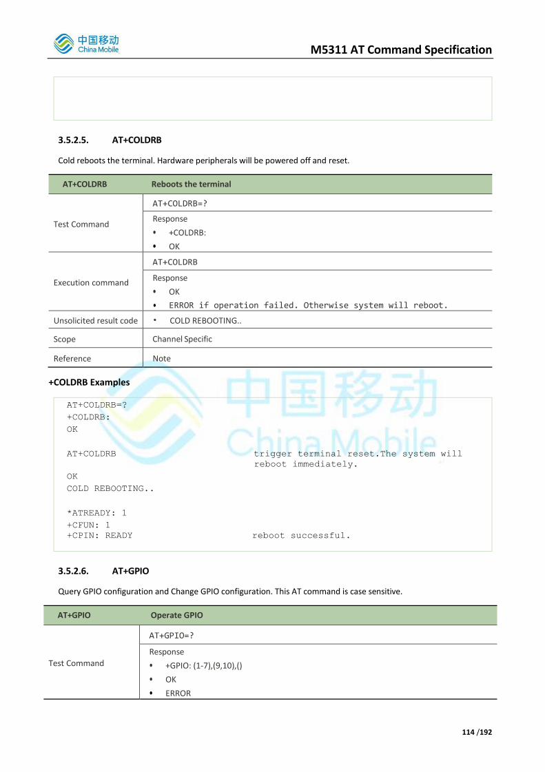
M5311 AT Command Specification
114 /192
3.5.2.5. AT+COLDRB
Cold reboots the terminal. Hardware peripherals will be powered off and reset.
AT+COLDRB Reboots the terminal
Test Command
AT+COLDRB=?
Response
• +COLDRB:
• OK
Execution command
AT+COLDRB
Response
• OK
• ERROR if operation failed. Otherwise system will reboot.
Unsolicited result code • COLD REBOOTING..
Scope Channel Specific
Reference Note
+COLDRB Examples
AT+COLDRB=?
+COLDRB:
OK
AT+COLDRB trigger terminal reset.The system will
reboot immediately.
OK
COLD REBOOTING..
*ATREADY: 1
+CFUN: 1
+CPIN: READY reboot successful.
3.5.2.6. AT+GPIO
Query GPIO configuration and Change GPIO configuration. This AT command is case sensitive.
AT+GPIO Operate GPIO
Test Command
AT+GPIO=?
Response
• +GPIO: (1-7),(9,10),()
• OK
• ERROR
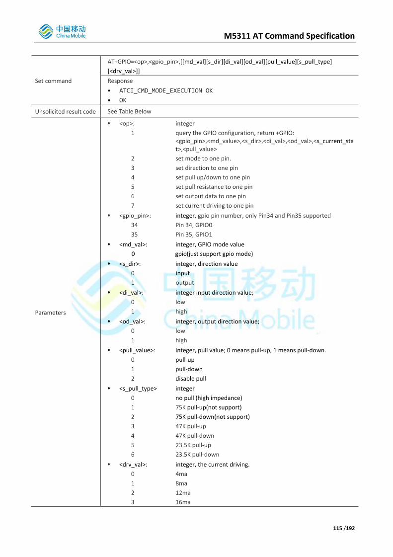
M5311 AT Command Specification
115 /192
Set command
AT+GPIO=<op>,<gpio_pin>,[[md_val][s_dir][di_val][od_val][pull_value][s_pull_type]
[<drv_val>]]
Response
• ATCI_CMD_MODE_EXECUTION OK
• OK
Unsolicited result code See Table Below
Parameters
• <op>: integer
1 query the GPIO configuration, return +GPIO: <gpio_pin>,<md_value>,<s_dir>,<di_val>,<od_val>,<s_current_stat>,<pull_value>
2 set mode to one pin.
3 set direction to one pin
4 set pull up/down to one pin
5 set pull resistance to one pin
6 set output data to one pin
7 set current driving to one pin
• <gpio_pin>: integer, gpio pin number, only Pin34 and Pin35 supported
34 Pin 34, GPIO0
35 Pin 35, GPIO1
• <md_val>: integer, GPIO mode value
0 gpio(just support gpio mode)
• <s_dir>: integer, direction value
0 input
1 output
• <di_val>: integer input direction value;
0 low
1 high
• <od_val>: integer, output direction value;
0 low
1 high
• <pull_value>: integer, pull value; 0 means pull-up, 1 means pull-down.
0 pull-up
1 pull-down
2 disable pull
• <s_pull_type> integer
0 no pull (high impedance)
1 75K pull-up(not support)
2 75K pull-down(not support)
3 47K pull-up
4 47K pull-down
5 23.5K pull-up
6 23.5K pull-down
• <drv_val>: integer, the current driving.
0 4ma
1 8ma
2 12ma
3 16ma

M5311 AT Command Specification
116 /192
Scope Channel Specific
Reference Note
Command Possible URC(s)
+GPIO=1,<gpio_pin> +GPIO: <gpio_pin>, <md_val>,<s_dir>, <di_val>, <od_val>,<drv_val>, <s_pull_type>
+GPIO=2,<gpio_pin>, <mod_val> <gpio_pin>,<md_val>
+GPIO=3,<gpio_pin>, <di_val> <gpio_pin>,<s_dir>
+GPIO=4,<gpio_pin>,<pull_val> <gpio_pin>,<s_pull_type>
+GPIO=5,<gpio_pin>,<s_pull_type> <gpio_pin>,<s_pull_type>
+GPIO=6,<gpio_pin>, <od_val> <gpio_pin>,<od_val>
+GPIO=7,<gpio_pin>, <drv_val> <gpio_pin>,<drv_val>
+GPIO Examples
at+gpio=1,34 //get GPIO_9 status
+GPIO: 34,0,1,1,1,0,0 //GPIO 9 in input mode, input value is low
OK
AT+GPIO=3,34,1 //set GPIO_9 to output direction
34,1
OK
AT+GPIO=6,34,0 //set output low voltage
34,0
OK
AT+GPIO=7,34,3 set GPIO_9 current to 16mA
34,3
OK
AT+GPIO=4,34,1 //set GPIO_9 to pull-down state
OK
AT+GPIO=3,34,0 //set GPIO_9 to input direction
34,0
OK
AT+GPIO=4,34,1 //set GPIO_9 to pull-down state
34,4
OK
at+gpio=5,34,0 //set GPIO_9 to high impedance
34,0
OK
3.5.2.7. AT+SM

M5311 AT Command Specification
117 /192
Set the sleep mode.
AT+SM Set the sleep mode
Set command
AT+SM=<op>
Response
• OK
• ERROR
Parameters
• <op>: string
LOCK acquire a temporary lock to prevent system enter sleep.
UNLOCK release the temporary lock acquired by AT+SM=LOCK command.
LOCK_FOREVER acquire a lock to prevent system enter sleep. This lock will be written into NVDM, so it will still valid even after reboot.
UNLOCK_FOREVER release lock acquired by AT+SM=LOCK_FOREVER command, and clear the NVDM data.
show lock status. All these setting will be written into NVDM,
will still take effect after reboot
Scope Channel Specific
Reference Note
+SM Examples
AT+SM=LOCK //acquire a lock to prevent system enter sleep.
OK
AT+SM=UNLOCK //release lock acquired by AT+SM=LOCK.
OK
AT+SM=LOCK_FOREVER //acquire a lock to prevent system enter sleep, this
lock will stay valid even after reboot.
OK
AT+SM=UNLOCK_FOREVER //release a lock acquired by AT+SM=LOCK_FOREVER
command.
OK
3.5.2.8. AT+EPORT
These AT commands are used to show or modify serial port assignment for the application, show or modify parameters of serial port devices, and switch serial port for the application, the setting will work after module reboot.
AT+EPORT Control and query serial port
Test Command
AT+EPORT=?
Response
• usage
• OK
Set command +EPORT=<op>[,<param1>…]

M5311 AT Command Specification
118 /192
Response
• +EPORT: <param2>
• OK
• ERROR
Parameters
• <op>: integer
0 display port assignment for applications/users.
1 reassign port for the specific applications/users and store in nvdm.
2 switch old port to specific port for the specific applications/users.
3 modify parameters of port service devices.
4 show parameters of port service devices
• <param1>… more parameters in AT command
If <op> is 1 or 2, <param1>… is <owner_name>,<port_id> in AT command
If <op> is 3, <param1>… is <port_id>,<baudrate> in AT command
If <op> is 4, <port_id>,<baudrate> in AT response
• <owner_name> string
Application name that uses port service. For example,
“uls” HSL log
“emmi” GKI log
• <port_id> integer
The specific device of port service support. Just support 0,
0 DBG(PIN 1-2)
Like as
o AT+EPORT=1,<owner_name>,<port_id>
o AT+EPORT=2,<owner_name>,<port_id>
• <baudrate> integer
The specific baudrate of port service device
Like as
o +EPORT=3,<port_id>,<baudrate>
Scope Channel Specific
Reference Note
Command Possible URC(s)
+EPORT=0 +EPORT: <owner_name>,<port_id>
+EPORT=1,<owner_name>,<port_id> None
+EPORT=2,<owner_name>,<port_id> None
+EPORT=3,<port_id>,<baudrate> None
+EPORT=4 +EPORT:<port_id>,<baudrate>
+EPORT Examples
AT+EPORT=0 display port assignment for
applications/users
+EPORT:
uls,2
connl,1

M5311 AT Command Specification
119 /192
emmi,0
OK
AT+EPORT=1,emmi,0 reassign port for the GKI and store in NVDM.
OK
AT+EPORT=3,0,921600 set UART0’s baud rate to 921600bps.
OK
AT+EPORT=4 show current parameters stored in NVDM.
+EPORT:
0,921600
1,115200
2,115200
3,115200
4,none
5,none
OK
3.5.2.9. AT+CMADC
AT+CMADC Read ADC
Test Command
AT+CMADC=?
Response
• +CMADC: (0-1)
• OK
Execution command
AT+CMADC=<chanel>
Response
• +CMADC: <voltage>
• OK
• If error is related to wrong AT syntax:
+CMADC: Over range!
ERROR
Parameters
<chanel> integer type
0 Read ADC from ADC0 (Pin38)
1 Read ADC from ADC1(Currently not supported)
<voltage> integer type, 0-1399. Indicate the ADC voltage.
Scope Channel Specific
Reference Note
+CMADC Examples
AT+CMADC=?
+CMADC: (0-1)
OK
AT+CMSYSCTRL=0 //ADC0

M5311 AT Command Specification
120 /192
+CMADC: 977mV
OK
AT+CMADC=0
+CMADC: Over range!
ERROR
3.5.2.10. AT+CMSYSCTRL
The command enable/disable output of the sleep/net status.
AT+CMSYSCTRL Enable output of sleep/net status
Test Command
AT+CMSYSCTRL=?
Response
• +CMSYSTRL: (0-1)(0-2)
• OK
Read command
AT+CMSYSCTRL?
Response
• <status_mode>,<wakeupout_mode>[,<nonreg_h>,<reg_h>,<nonreg_l>,<reg_l>]
• OK
Execution command
AT+CMSYSCTRL=<op>,<mode>[,<nonreg_h>,<reg_h>,<nonreg_l>,<reg_l>]
Response
• OK
• If error is related to wrong AT syntax:
+CME ERROR: <err>
Parameters
<op> integer type
0 Select operation STATE (Pin21)
1 Select operation WAKEUP-OUT (Pin16)
<mode> integer type
0 Disable the output of status from STATE.
1 <op>=0 : Enable the output of light sleep status from STATE. When M5311 enter light sleep mode, it will Output high.
<op>=1: Enable the output of deep sleep status from WAKEUP-OUT. When M5311 wakeup out from deep sleep, it will Output high.
2 integer type, Only in the case of <op>=0, Enable the output of EPS registration status from STATE. When M5311 EPS has been not registered, by default, it will cycle output high of 80ms and low of 800ms. When M5311 EPS has been registered, by default, iit will cycle output high of 80ms and low of 3000ms. When M5311 enter deep sleep mode, it will turn off until wake up.
<status_mode> integer type, Indicate <mode> of the STATE.
<wakeupout_mode> integer type, Indicate <mode> of the WAKEUP_OUT.
<nonreg_h> integer type, Only in the case of <op>=0 &<mode>=2, default 80ms, range
40-65535(ms), it represents the high level duration in unregistered.

M5311 AT Command Specification
121 /192
<reg_h> integer type, Only in the case of <op>=0 &<mode>=2, default 80ms, range
40-65535(ms), it represents the high level duration in registered. <nonreg_h> integer type, Only in the case of <op>=0 &<mode>=2, default 800ms,
range 40-65535(ms), it represents the low level duration in unregistered.
<reg_h> integer type, Only in the case of <op>=0 &<mode>=2, default 3000ms, range 40-65535(ms), it represents the low level duration in registered.
Scope Channel Specific
Reference Note
• The default value is disable report of the sleep status.
EPS registration default status(status_mode:2)
EPS registration status Description
unregistered 80ms high/800ms low
registered 80ms high/3000ms low
+CMSYSCTRL Examples
AT+CMSYSCTRL=?
+CMSYSTRL: (0-1)(0-2)
OK
AT+CMSYSCTRL=0,2,50,300,100,800 //enable net status output
//output(STATE)
OK
AT+CMSYSCTRL?
2,0,50,300,100,800
OK
AT+CMSYSCTRL=0,1 //enable light sleep status
//output(STATE)
OK
AT+CMSYSCTRL=1,1 //enable deep sleep status
//output(WAKEUP_OUT)
OK
AT+CMSYSCTRL?
1,1
OK
3.5.2.11. AT+TAUAC
This command is required for periodic TAU value (T3412) allocated to the UE in E-UTRAN.
AT+TAUAC Read periodic TAU value
Test Command AT+TAUAC=?

M5311 AT Command Specification
122 /192
Response
• +TAUAC: (0-1116000)
• OK
Read command
AT+TAUAC?
Response
• +TAUAC: <periodic_tau>
• OK
If error is related to wrong AT syntax
+CME ERROR: <err>
Parameter • <periodic_tau> integer type, range 0-1116000(s). Indicates the periodic TAU
value (T3412) allocated to the UE in E-UTRAN.
Scope Generic
Reference Note
+ICCID examples
AT+TAUAC=?
+TAUAC: (0-1116000)
OK
AT+TAUAC?
+TAUAC: 3240
OK
3.5.2.12. AT+ICCID
This command is required for Windows 7 NDIS driver. It is used to read the USIM ICCID field (EFIccId).
AT+ICCID Read USIM ICCID File
Execution command
AT+ICCID
Response
• +ICCID: <ICCID>
• OK
If error is related to wrong AT syntax
• +CME ERROR: <err>
Parameter • <ICCID> International Circuit Card (ICC) ID of the (U)SIM. Formatted as a
numeric string without double quotes. The string can be up to a maximum of 20 digits long.
Scope Generic
Reference Note
+ICCID examples
AT+ICCID Execution command
+ICCID: 56979649586978380293
OK

M5311 AT Command Specification
123 /192
3.5.2.13. AT+CLPLMN
Clear PLMN, EARFCN, PCI attachment record.
AT+CLPLMN Clear PLMN, EARFCN, PCI attachment record
Execution command
AT+CLPLMN
Response
• +CLPLMN: <status>
• OK
If error is related to wrong AT syntax
• +CME ERROR: <err>
Parameter
• <status> result of clear record
0 Successful
1 NVDM corrupt
2 Other failure
Scope Generic
Reference Note
+CLPLMN examples
AT+CLPLMN Execution command
+CLPLMN: 0 Clear record success
OK
3.5.2.14. AT*ENGINFO
This command is used to query current network status, and modem status information for serving cell.
AT*ENGINFO Report Network State
Test Command
AT*ENGINFO=?
Response
• *ENGINFO: (list of supported
<mode>)
• OK
Execution command
AT*ENGINFO=<mode>
Response
• If <mode> = 0 display serving cell and up to 4 neighbor cell information:
o *ENGINFOSC: <sc_earfcn>,<sc_earfcn_offset>,<sc_pci>,<sc_cellid>,[<sc_rsrp>],[<sc_rsrq>],[<sc_rssi>],[<sc_snr>],<sc_band>,<sc_tac>,[<sc_ecl>],[<sc_tx_pwr>]
o [<CR><LF>*ENGINFONC:<nc_earfcn>,<nc_earfcn_offset>,<nc_pci>,<nc_rsrp>
o […]]
o OK
• If <mode> = 1 display data transfer information only if modem in RRC-CONNECTED state:
o *ENGINFODT: <RLC_UL_BLER>,<RLC_DL_BLER>,<MAC_UL_BLER>,<MAC_DL_BLER>,<MAC_

M5311 AT Command Specification
124 /192
UL_total_bytes>,<MAC_DL_total_bytes>,<MAC_UL_total_HARQ_TX>,<MAC_DL_total_HARQ_TX>,<MAC_UL_HARQ_re_TX>,<MAC_DL_HARQ_re_TX>,<RLC_ UL_tput>,<RLC_DL_tput>,<MAC_UL_tput>,<MAC_DL_tput>
o OK
• If error is related to wrong AT syntax or incorrect <mode> or UE in incorrect state
o +CME ERROR: <err>
Parameters
<mode> Integer value indicating requested engineering information. 0: Radio information for serving and neighbor cells
Serving Cell/Neighbor Cell information:
<sc_earfcn> Integer value indicating the EARFCN for serving cell. Range 0-262143
<sc_earfcn_offset> Integer value indicating the EARFCN offset for serving cell: 0: Offset of -2 1: Offset of -1 2: Offset of -0.5 3: Offset of 0 4: Offset of 1
<sc_pci> Integer value indicating the serving cell physical cell ID. Range 0 – 503.
<sc_cellid> String type; four byte (28 bit) cell ID in hexadecimal format for serving cell.
<sc_rsrp> Signed integer indicating serving cell RSRP value in units of dBm (can be negative value). Available only in RRC-IDLE state.
<sc_rsrq> Signed integer indicating serving cell RSRQ value in units of dB (can be negative value). Available only in RRC-IDLE state.
<sc_rssi> Signed integer indicating serving cell RSSI value in units of dBm (can be negative value). Available only in RRC-IDLE state.
<sc_snr> Signed integer value. Last SNR value for serving cell in units of dB. Available only in RRC-IDLE state.
<sc_band> Integer value; current serving cell band
<sc_tac> String type; two byte tracking area code (TAC) in hexadecimal format (e.g. "00C3" equals 195 in decimal).
<sc_ecl> Integer value. Last Enhanced Coverage Level (ECL) value for serving cell.Range 0-2.
<sc_tx_pwr> Signed integer value indicating current UE transmit power. Units of cBm Centibels relative to one milliwatt (can be negative value).
<nc_earfcn> Integer value indicating the EARFCN for neighbor cell. Range 0-262143
<nc_earfcn_offset> Integer value indicating the EARFCN offset for neighbor cell: 0: Offset of -2 1: Offset of -1 2: Offset of -0.5 3: Offset of 0 4: Offset of 1
<nc_pci> Integer value indicating the neighbor cell physical cell ID. Range 0-503.
<nc_rsrp> Signed integer indicating neighbor cell RSRP value in units of dBm (can be negative value).
Data Transfer Information:
<RLC_UL_BLER> Integer value. Represented in % value (range 0 to 100). UL block error rate (as per IRQ) in RLC. Calculated over all established RLC AM radio bearers. Calculated from the beginning of successfully established/resumed RRC connection or since previous AT*ENGINFO query with <mode>=1, whichever is later. Only valid in RRC-CONNECTED state.
<RLC_DL_BLER> Integer value Represented in % value (range 0 to 100). DL block error rate

M5311 AT Command Specification
125 /192
(as per ARQ) in RLC. Calculated over all established RLC AM radio bearers. Calculated from the beginning of successfully established / resumed RRC connection, or since previous AT*ENGINFO query with <mode>=1, whichever is later. Available only in RRC-CONNECTED state.
<MAC_UL_BLER> Integer value. Represented in % value (range 0 to 100). UL block error rate (as per HARQ) in MAC for UL-SCH. Calculated from the beginning of successfully established / resumed / re-established RRC connection, or since previous AT*ENGINFO query with <mode>=1, whichever is later. Available only in RRC-CONNECTED state.
<MAC_DL_BLER> Integer value. Represented in % value (range 0 to 100). DL block error rate (as per HARQ) in MAC for DL-SCH, excluding BCCH. Calculated from the beginning of successfully established / resumed / re-established RRC connection, or since previous AT*ENGINFO query with <mode>=1, whichever is later. Available only in RRC-CONNECTED state.
< MAC_UL_total_bytes> Integer value. Total number of transport block bytes (re)transmitted on UL-SCH. Calculated for UL-SCH over all HARQ transmissions and retransmissions. Calculated from the beginning of successfully established / resumed / re-established RRC connection, or since previous AT*ENGINFO query with <mode>=1, whichever is later. Available only in RRC-CONNECTED state. Unit: bytes
<MAC_DL_total_bytes> Integer value. Total number of transport block bytes (re)transmitted on DL-SCH, excluding BCCH. Calculated from the beginning of successfully established / resumed /re-established RRC connection, or since previous AT*ENGINFO query with <mode>=1, whichever is later. Available only in RRC-CONNECTED state. Unit: bytes
<MAC_UL_total_HARQ_TX> Integer value. Total number of HARQ (re)transmissions for transport blocks on UL-SCH. Calculated from the beginning of successfully established / resumed / re-established RRC connection, or since previous AT*ENGINFO query with <mode>=1, whichever is later. Available only in RRC-CONNECTED state. Unit: (re)transmissions
< MAC_DL_total_HARQ_TX> Integer value. Total number of HARQ (re)transmissions for transport blocks on DL-SCH, excluding BCCH. Calculated from the beginning of successfully established / resumed / re-established RRC connection, or since previous AT*ENGINFO query with <mode>=1, whichever is later. Available only in RRC-CONNECTED state. Unit: (re)transmissions
< MAC_UL_HARQ_re_TX> Integer value. Number of HARQ retransmissions for transport blocks on UL-SCH. Calculated from the beginning of successfully established / resumed / re-established RRC connection, or since previous AT*ENGINFO query with <mode>=1, whichever is later. Available only in RRC-CONNECTED state. Unit: retransmissions
<MAC_DL_HARQ_re_TX> Integer value. Number of HARQ retransmissions for transport blocks on DL-SCH, excluding BCCH. Calculated from the beginning of successfully established / resumed / re-established RRC connection, or since previous AT*ENGINFO query with <mode>=1, whichever is later. Available only in RRC- CONNECTED state. Unit: retransmissions.
<RLC_UL_tput> Integer value. RLC uplink throughput. Calculated over all established RLC AM radio bearers. Calculated from the beginning of successfully established / resumed RRC connection, or since previous AT*ENGINFO query with <mode>=1, whichever is later. Available only in RRC-CONNECTED state. Unit: kbits / s
<RLC_DL_tput> Integer value. RLC downlink throughput. Calculated over all established RLC AM radio bearers Calculated from the beginning of successfully established / resumed RRC connection, or since previous AT*ENGINFO

M5311 AT Command Specification
126 /192
query with <mode>=1, whichever is later. Available only in RRC-CONNECTED state. Unit: kbits / s
<MAC_UL_tput> Integer value. UL throughput in MAC for UL-SCH. Calculated from the beginning of successfully established / resumed / re-established RRC connection, or since previous AT*ENGINFO query with <mode>=1, whichever is later. Available only in RRC-CONNECTED state. Unit: kbits / s
<MAC_DL_tput> Integer value. DL throughput in MAC for DL-SCH, excluding BCCH. Calculated from the beginning of successfully established / resumed / re-established RRC connection, or since previous AT*ENGINFO query with <mode>=1, whichever is later. Available only in RRC-CONNECTED state. Unit: kbits / s
Scope Channel specific
Reference
Note
• If modem is not in RRC-CONNECTED state then *ENGINFODT: will not be generated for <mode> = 1. Only OK response will be generated.
*ENGINFO examples
(power up in in CFUN=0 mode)
AT*ENGINFO=0
ERROR Cannot display information in CFUN=0 mode
AT+CFUN=1
OK
(Not yet registered to network)
AT*ENGINFO=0
OK
(Registered to network)
AT*ENGINFO=0
*ENGINFOSC: 3701,3,69,”27447553”,-1073,-1175,-1145,290,18,11,0,0,-35
*ENGINFONC: 3701,0,60,-1073
*ENGINFONC: 3369,1,37,-1073
*ENGINFONC: 3210,2,23,-1073
*ENGINFONC: 3001,1,15,-1073
OK
AT*ENGINFO=1
(Modem not in RRC-CONNECTED state – so no valid information) OK
(Modem in RRC-CONNECTED state – so information valid) *ENGINFODT: 10,5,8,3,1080,900,80,80,100,100,1000,980,1030,1000
OK
3.5.2.15. AT*FRCLLCK
This command is used to lock UE to specific frequency and optionally Cell ID.
AT*MFRCLLCK Frequency & Cell Lock
Read command AT*FRCLLCK?
Response

M5311 AT Command Specification
127 /192
• *FRCLLCK: <lock>[,<earfcn>,<earfcn_offset>[,<pci>]]
• OK
Execution command
AT*FRCLLCK=<lock>[,<earfcn>,<earfcn_offset>[,<pci>]]
Response
• OK
• If error is related to wrong AT syntax or incorrect parameters.
o +CME ERROR: <err>
Parameters
<lock> Integer value indicating whether to activate lock, or remove lock:
0: Remove lock 1: Activate lock
<earfcn> Integer value indicating requested EARFCN on which to lock. Range 0- 262143. Value of 0 indicates to remove any lock for EARFCN and Cell
<earfcn_offset> Integer value indicating requested EARFCN offset:
0: Offset of -2 1: Offset of -1
2: Offset of -0.5
3: Offset of 0
4: Offset of 1 <pci> Integer value: Physical cell ID. Range: 0-503
Scope Generic
Reference Note
*FRCLLCK examples
AT*FRCLLCK=1,10,3,301 Lock to EARFCN 10, offset 0, PCI 301
OK
AT*FRCLLCK=0 Remove lock
OK
3.5.2.16. AT*SPCHSC
This command is used to select new or old scrambling code for NPCSCH. This is because code has been updated by 3GPPP, and UE needs to select correct code for network.
AT*SPCHSC Set Scrambling Algorithm for NPDSCH
Test Command
AT*SPCHSC=?
Response
• *SPCHSC: (0-1)
• OK
Read command
AT*SPCHSC?
Response
• *SPCHSC: <mode>
• OK
Execution command
AT*SPCHSC=<mode>
Response
• OK
• If error is related to wrong AT syntax or incorrect <mode>

M5311 AT Command Specification
128 /192
o +CME ERROR: <err>
Parameters <mode> 0: New algorithm (default)
1: Old algorithm
Scope Generic
Reference Note
*SPCHSC examples
AT*FRCLLCK=1,10,3,301 Lock to EARFCN 10, offset 0, PCI 301
OK
AT*FRCLLCK=0 Remove lock
OK
AT+SPCHSC=1 Select old algorithm
OK
3.5.2.17. AT*CGDEFCONT
This command is used to set the PSD connection settings for PDN connection on power up. In NB-IOT, when you attach to the NB-IOT network on power-on then you must also perform a PDN connection setup. In order to allow this to happen we must store PDN connection settings in NVRAM to be used by the modem during the attach procedure.
Note, that if this command is not entered, there will already be default settings stored in NVRAM at compile time.
Note that this command is similar in syntax to AT+CGDCONT, but without the <cid> parameter, and with additional parameters <username> and <password>.
AT*CGDEFCONT Set Default PSD Connection Settings
Test Command
AT*CGDEFCONT=?
Response
• *CGDEFCONT: (List of supported <PDP_type>)
• OK
Read command
AT*CGDEFCONT?
Response
• *CGDEFCONT:<PDP_type>,<APN>,<username>,<password>
• OK
Execution command
AT*CGDEFCONT=<PDP_type>[,<APN>[,<username>[,<password>]]]
Response
• OK
• If error is related to wrong AT syntax or unsupported <mode>:
o +CME ERROR: <err>
Parameters
<PDP_type> (Packet Data Protocol type) a string parameter which specifies the type of packet data protocol : IP Internet Protocol (IETF STD 5)
IPV6 Internet Protocol, version 6 (IETF RFC 2460)
IPV4V6 Virtual <PDP_type) introduced to handle dual IP stack UE
capability (see 3GPP TS 24.301).
Non-IP Transfer of Non-IP data to external packet data Network

M5311 AT Command Specification
129 /192
(see 3GPP TS 24.301).
<APN> (Access Point Name) a string parameter that is a logical name that is used to select the GGSN or the external packet data network. If the value is null or omitted, then the subscription value will be requested.
<username> String value. Username for the connection to the service provider
<password> String value. Password for the connection to the service provider
Scope Generic
Reference Note
*CGDEFCONT examples
Mobile in CFUN=0 Mode
AT*CGDEFCONT=? Test command
*MCGDEFCONT: (“IP”,”IPV6”,”IPV4V6”,”Non-IP”) IP versions supported
OK
AT*CGDEFCONT? Read command
*CGDEFCONT: “IP”,”internet”,”username”,”password” Default settings in
NVRAM
OK
AT*CGDEFCONT=”IPV4V6”,”web.o2.co.uk”,”web”,”web” Set command. Set
default settings for O2 network, IPV4/V6
OK
AT+CFUN=1
OK
(Mobile attaches to NB-IOT network and sets up PDN connection using
default settings set with AT*CGDEFCONT)
AT+CGACT?
+CGACT: 1,1
OK
3.5.2.18. AT*PLNMURI
This command is used to enable/disable generation of unsolicited result code to indicate when the aggregated “maximum number of packets” for a particular PLMN changes.
AT*PLMNURI PLMN Rate Control Indication
Test Command
AT*PLMNURI=?
Response
• *PLMNURI: (list of supported <mode>s)
• OK
Read command
AT*PLMNURI?
Response
• *PLMNURI: <mode>,<urc_active>[,<Serving_PLMN_rate_control_value>]

M5311 AT Command Specification
130 /192
• OK
Execution command
AT*PLMNURI=<mode>
Response
• OK
Unsolicited result code *PLMNURI:<urc_active>[,<Serving_PLMN_rate_control_value>]
Parameters
• <mode>: integer type
o 0 – No unsolicited result codes are forwarded to the TE.
o 1 – Forward unsolicited result codes to the TE.
• <urc_active>: integer type. Indicates if uplink rate control is active or not:
o 0 – inactive
o 1 – active
• <Serving_PLMN_rate_control_value>: integer type; indicates the maximum number of uplink messages the UE is allowed to send in a 6 minute interval. This refers to octet 3 to 4 of the Serving PLMN rate control IE as specified in 3GPP TS 24.301 sub-clause 9.9.4.28.
Scope Channel Specific
Reference Note
3.5.2.19. AT*NBIOTDT
This command is used to set the NB-IOT data type per APN (Normal or Exceptional data).
AT*MNBIOTDT NB-IOT Data Type
Test Command
AT*NBIOTDT=?
Response
• *NBIOTDT: (list of supported <types>s)
• OK
Read command
AT*NBIOTDT?
Response
• Displays <type> for all active PDP contexts:
o [*NBIOTDT:<cid>,type]
o [<CR><LF>*MNBIOTDT:<cid>,<type>]
o […]]
o OK
Execution command
AT*NBIOTDT=<type>[,<cid>[,<cid>[,…]]]
Response
• OK
Parameters
• <type>: integer type
0 Normal data (default)
1 Exceptional data
• <cid>: integer type. Specifies a particular PDP context definition.
If no <cid>s are specified the command sets <type> for all active PDP contexts.
Scope Generic
Reference Note
• The UE will not remember this setting over sleep cycles (i.e. the UE will fall

M5311 AT Command Specification
131 /192
back to default setting after sleep)
3.5.2.20. AT*NBIOTRAI
This command is used to set the NB-IOT release assistance indication as follows:
No information available
TE will send only 1 UL packet and no DL packet is expected
TE will send only 1 UL packet and only 1 DL packet is expected
AT*NBIOTRAI NB-IOT release assistance indication
Test Command
AT*NBIOTRAI=?
Response
• *NBIOTRAI: (range of supported <rai>s)
• OK
Read command
AT*NBIOTRAI?
Response
• *NBIOTRAI: <rai>
• OK
Execution command
AT*NBIOTRAI=<rai>
Response
• OK
Parameters
• <rai>: integer type. Specifies release assistance information:
o 0: No information available (or none of the other options apply) (default)
o 1: TE will send only 1 UL packet and no DL packets expected
o 2: TE will send only 1 UL packet and only 1 DL packet expected
Scope Generic
Reference
Note
• This command may never be required as it is likely that the TE will not know this information.
• Modem applies specified <rai> value only to next UL packet sent by TE
• TE will not remember this setting over sleep cycles (i.e. will fall back to default after sleep)
3.5.2.21. AT*HOMENW
This command is required for the NDIS driver in order to display the home network information in alphanumeric (short and long format) and numeric format. This information is extracted from the IMSI.
AT*HOMENW Display Home Network Information
Execution command
AT*HOMENW
Response
UE returns the home network information (extracted from the IMSI) in numeric, short alpha and long alpha formats.
• *HOMENW: <oper long alpha>, <oper short alpha>, <oper numeric>
• OK

M5311 AT Command Specification
132 /192
If error is related to wrong AT syntax
• +CME ERROR: <err>
Parameter
• <oper long alpha> Home operator in long alphanumeric format
• <oper short alpha> Home operator in short alphanumeric format
• <oper numeric> Home operator in numeric GSM Location Area Identification number format
Scope Generic
Reference Note
*HOMENW examples
AT*HOMENW Execution command. Display home network
Information
*HOMENW: "46004","46004","46004"
OK
3.5.2.22. AT*CMSPN
AT*CMSPN Service Provider Name (from SIM)
Read command
AT*CMSPN?
Response
• *CMSPN: <spn>,<display mode>
• +CME ERROR: <err>
Parameters
• <spn> string type; service provider name on SIM
• <display mode> 0 no PLMN. Already registered on PLMN
1 display PLMN
Scope o Channel Specific (reads from generic SPN setting)
Reference Note
3.5.2.23. AT*CMUNSOL
AT*CMUNSOL Extra Unsolicited Indications
Test command
AT*MUNSOL=?
Response
• *CMUNSOL: (list of supported <ind>s)
Set command
AT*MUNSOL=<ind>,<mode>
Response
• OK
• +CME ERROR: <err>
Parameters
• <ind> values currently reserved by the present document:
o “SQ” Signal Quality
Displays signal strength and quality information for the current serving cell in form *MSQN: <rssi>,<rsrq>,<rsrp> when values are measured by the protocol stack. Note that the current signal quality level is displayed immediately if this unsolicited event is enabled and there is already valid signal quality information available.
o “FN” Forbidden Networks Available Only
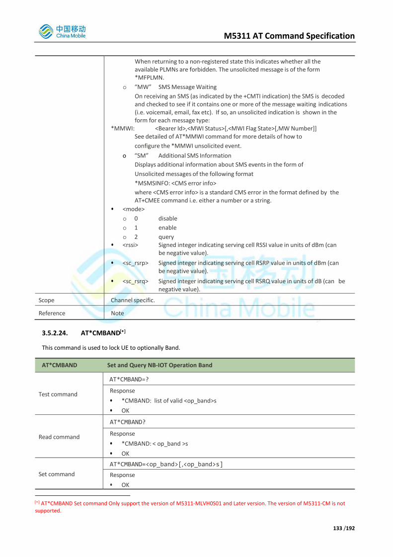
M5311 AT Command Specification
133 /192
When returning to a non-registered state this indicates whether all the available PLMNs are forbidden. The unsolicited message is of the form *MFPLMN.
o “MW” SMS Message Waiting
On receiving an SMS (as indicated by the +CMTI indication) the SMS is decoded and checked to see if it contains one or more of the message waiting indications (i.e. voicemail, email, fax etc). If so, an unsolicited indication is shown in the form for each message type:
*MMWI: <Bearer Id>,<MWI Status>[,<MWI Flag State>[,MW Number]] See detailed of AT*MMWI command for more details of how to
configure the *MMWI unsolicited event.
o “SM” Additional SMS Information
Displays additional information about SMS events in the form of
Unsolicited messages of the following format
*MSMSINFO: <CMS error info>
where <CMS error info> is a standard CMS error in the format defined by the AT+CMEE command i.e. either a number or a string.
• <mode>
o 0 disable
o 1 enable
o 2 query • <rssi> Signed integer indicating serving cell RSSI value in units of dBm (can
be negative value).
• <sc_rsrp> Signed integer indicating serving cell RSRP value in units of dBm (can be negative value).
• <sc_rsrq> Signed integer indicating serving cell RSRQ value in units of dB (can be negative value).
Scope Channel specific.
Reference Note
3.5.2.24. AT*CMBAND
This command is used to lock UE to optionally Band.
AT*CMBAND Set and Query NB-IOT Operation Band
Test command
AT*CMBAND=?
Response
• *CMBAND: list of valid <op_band>s
• OK
Read command
AT*CMBAND?
Response
• *CMBAND: < op_band >s
• OK
Set command
AT*CMBAND=<op_band>[,<op_band>s]
Response
• OK
AT*CMBAND Set command Only support the version of M5311-MLVH0S01 and Later version. The version of M5311-CM is not supported.

M5311 AT Command Specification
134 /192
Parameters
<op_band> Integer type, Optional range 0,3,5,8
0 Restore Defaults, <op_band>s=1,3,5,8,28
1,3,5,8,28 Selected NB-IOT band
Scope Channel specific.
Reference Note
• This command takes effect following the issuance of rebooting system.
3.5.2.25. AT*MATWAKEUP
This command is used to enable an unsolicited result code on a channel that indicates when the module is woken up after a deep sleep.
AT*MATWAKEUP Enable Deep Sleep Wakeup Indication
Test Command
AT*MATWAKEUP=?
Response
• *MATWAKEUP: (0-1)
• OK
Read command
AT*MATWAKEUP?
Response
• *MATWAKEUP: <enable>
• OK
Execution command
AT*MATWAKEUP=<enable>
Response
• OK
• If error is related to wrong AT syntax or incorrect <mode>
o +CME ERROR: <err>
Unsolicited result code *WAKEUP
Parameters
• <enable>
o 0: Disable indication on this channel when module wakes up from deep sleep (default)
o 1: Enable indication on this channel when module wakes up from
deep sleep
Scope Channel specific
Reference Note
*MATWAKEUP examples
AT*MATWAKEUP=1 Enable wakeup indication
OK
(Modem wakes up after deep sleep)
*MATWAKEUP Modem fully woken up and ready to receive AT
commands/data
3.5.2.26. AT*SLEEP
This command is used to enable an unsolicited result code on a channel that indicates when the module is
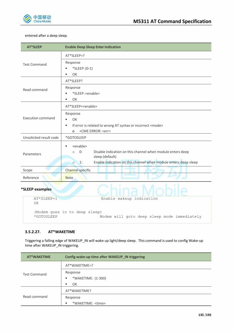
M5311 AT Command Specification
135 /192
entered after a deep sleep.
AT*SLEEP Enable Deep Sleep Enter Indication
Test Command
AT*SLEEP=?
Response
• *SLEEP: (0-1)
• OK
Read command
AT*SLEEP?
Response
• *SLEEP: <enable>
• OK
Execution command
AT*SLEEP=<enable>
Response
• OK
• If error is related to wrong AT syntax or incorrect <mode>
o +CME ERROR: <err>
Unsolicited result code *GOTOSLEEP
Parameters
• <enable>
o 0: Disable indication on this channel when module enters deep sleep (default)
o 1: Enable indication on this channel when module enters deep sleep
Scope Channel specific
Reference Note
*SLEEP examples
AT*SLEEP=1 Enable wakeup indication
OK
(Modem goes in to deep sleep)
*GOTOSLEEP Modem will goto deep sleep mode immediately
3.5.2.27. AT*WAKETIME
Triggering a falling edge of WAKEUP_IN will wake up light/deep sleep. This command is used to config Wake-up time after WAKEUP_IN triggering.
AT*WAKETIME Config wake-up time after WAKEUP_IN triggering
Test Command
AT*WAKETIME=?
Response
• *WAKETIME: (1-300)
• OK
Read command
AT*WAKETIME?
Response
• *WAKETIME: <time>

M5311 AT Command Specification
136 /192
• OK
Execution command
AT*WAKETIME =<time>
Response
• OK
• If error is related to wrong AT syntax or incorrect <mode>
o +CME ERROR: <err>
Parameters <time> integer type, 1-300s, Default 10s.
Scope Channel specific
Reference Note
*WAKETIME examples
AT* WAKETIME=? *WAKETIME: (10-300)
OK
AT*WAKETIME?
*WAKETIME: 10 // Default 10s. WAKEUP_IN will lock the wake-up mode for 10s from deep/light sleep.
OK
AT*WAKETIME=5 //WAKEUP_IN will lock the wake-up mode for 5s
from deep/light sleep.
OK
3.5.2.28. AT*ENTERSLEEP
Triggering a falling edge of WAKEUP_IN will wake up light/deep sleep and lock the wake-up mode for some time (see AT*WAKETIME). If the terminal does not do network related services, it will still be in the light/deep sleep mode, After the wake-up time elapse, it will enter sleep mode again. This command can be used to enter light/deep sleep immediately in this case without waiting for the wake-up timer to end.
By default, AT command will also lock the wake-up mode for 10s. If the terminal does not do network related services, The terminal will enter sleep mode at least 10 s after you send the last AT command, This command can be used to enter light/deep sleep immediately in this case.
AT*ENTERSLEEP Enter light/deep sleep mode immediately
Execution command
AT*ENTERSLEEP
Response
• OK
• If error is related to wrong AT syntax or incorrect <mode>
o +CME ERROR: <err>
Parameters None
Scope Channel specific
Reference Note
*ENTERSLEEP examples

M5311 AT Command Specification
137 /192
AT*MATWAKEUP=1 //Enable wakeup indication
OK
AT*SLEEP=1 //Enable wakeup indication
OK
AT*WAKETIME=20 //Set wake-up time 20s
OK
*GOTOSLEEP
*MATWAKEUP //Triggering a falling edge of WAKEUP_IN, It
will keep wake-up mode 20s
AT*ENTERSLEEP //Enter deep sleep immediately
OK
*GOTOSLEEP //Enter deep sleep
*MATWAKEUP //Triggering a falling edge of WAKEUP_IN
AT*WAKETIME=5 //Set wake-up time 5s, AT command will lock the wake-up mode as 10s.
OK
AT*ENTERSLEEP //Enter deep sleep immediately
OK
*GOTOSLEEP //Enter deep sleep
3.5.2.29. AT*EDRXCFG
The set command controls the setting of the UEs eDRX parameters. The command controls whether the UE wants to apply eDRX or not, as well as the requested eDRX value and requested paging time window value for each specified type of access technology.
The set command also controls the presentation of an unsolicited result code +CEDRXP: <AcTtype>[,<Requested_eDRX_value>[,<NW-provided_eDRX_value>[,<Paging_time_window>]]] when <n>=2 and there is a change in the eDRX parameters provided by the network.
A special form of the command can be given as *EDRXCFG=3. In this form, eDRX will be disabled and data for all parameters in the command *EDRXCFG will be removed or, if available, set to the manufacturer specific default values.
AT*EDRXCFG eDRX configuration
Test Command
AT*EDRXCFG=?
Response
• *EDRXCFG: (list of supported <mode>s),(list of supported <AcTtype>s),(list of supported <Requested_eDRX_value>s) ,(list of supported <Requested_Paging_time_window_value>s)
• OK
Only the M5311_CM version is supported.

M5311 AT Command Specification
138 /192
Read command
AT*EDRXCFG?
Response
• *ERDRXCFG: <AcTtype>,<Requested_eDRX_value>[,<Requested_Paging_time_window_value>]
• OK
• If error is related to wrong AT syntax or operation not allowed:
+CME ERROR: <err>
Execution command
AT*EDRXCFG=[<mode>,[,<AcTtype>[,<Requested_eDRX_value>[,<Requested_Paging_time_window_value>]]]]
Response
• OK
• If error is related to wrong AT syntax:
+CME ERROR: <err>
Unsolicited result code *+CEDRXP:<AcT-type>[,<Requested_eDRX_value>[,<NWprovided_eDRX_value>[,<Paging_time_window>]]]
Parameters
<mode> integer type, indicates to disable or enable the use of eDRX in the UE. This
parameter is applicable to all specified types of access technology, i.e. the
most recent setting of <mode> will take effect for all specified values of
<AcT>.
0 Disable the use of eDRX 1 Enable the use of eDRX 2 Enable the use of eDRX and enable the unsolicited result code +CEDRXP:
<AcT-type>[,<Requested_eDRX_value>[,<NWprovided_eDRX_value> [,<Paging_time_window>]]]
3 Disable the use of eDRX and discard all parameters for eDRX or, if available, reset to the manufacturer specific default values.
<AcT-type> integer type, indicates the type of access technology. This AT-command is
used to specify the relationship between the type of access technology
and the requested eDRX value.
0 Access technology is not using eDRX. This parameter value is only used
in the unsolicited result code.
5 E-UTRAN (NB-S1 mode)
<Requested_eDRX_value> string type; half a byte in a 4-bit format. The eDRX value
refers to bit 4 to 1 of octet 3 of the Extended DRX parameters
information element (see sub-clause 10.5.5.32 of 3GPP TS 24.008). For
the coding and the value range, see Extended DRX parameters
information element in 3GPP TS 24.008 Table 10.5.5.32/3GPP TS 24.008.
The default value, if available, is manufacturer specific.
<Requested_Paging_time_window_value> string type; half a byte in a 4-bit format. The
paging time window refers to bit 8 to 5 of octet 3 of the Extended DRX
parameters information element (see sub-clause 10.5.5.32 of 3GPP
TS 24.008). For the coding and the value range, see the Extended DRX
parameters information element in 3GPP TS 24.008 Table
10.5.5.32/3GPP TS 24.008.
<NW-provided_eDRX_value> string type; half a byte in a 4-bit format. The eDRX value
refers to bit 4 to 1 of octet 3 of the Extended DRX parameters information
element (see sub- clause 10.5.5.32 of 3GPP TS 24.008). For the coding and

M5311 AT Command Specification
139 /192
the value range, see Extended DRX parameters information element in
3GPP TS 24.008 Table 10.5.5.32/3GPP TS 24.008.
<Paging_time_window> string type; half a byte in a 4-bit format. The paging time
window refers to bit 8 to 5 of octet 3 of the Extended DRX parameters
information element (see sub-clause 10.5.5.32 of 3GPP TS 24.008). For
the coding and the value range, see the Extended DRX parameters
information element in 3GPP TS 24.008 Table 10.5.5.32/3GPP TS 24.008.
Scope Channel Specific
Reference Note
• The default value is disable report of the event.
3.5.2.30. AT*MDPDNP
AT*MDPDNP Default PDN Parameter
Test Command
AT*MDPDNP=?
Response
• *MDPDNP: (list of supported <n>s)
• OK
Read command
AT*MDPDNP?
Response
• *MDPDNP: <n>
• OK
• If error is related to wrong AT syntax or operation not allowed:
+CME ERROR: <err>
Execution command
AT*MDPDNP=[<n>]
Response
• OK
• If error is related to wrong AT syntax:
+CME ERROR: <err>
Unsolicited result code *MDPDNP: <APN>,<PDP type>
Parameters
<n> integer type
0 disable default PDN parameter unsolicited result code 1 enable default PDN parameter unsolicited result code
<APN> (Access Point Name) a string parameter, a logical name to select the GGSN
or the external packet data network.
<PDP_type> (Packet Data Protocol type) a string parameter which specifies the type
of packet data protocol :
IP Internet Protocol (IETF STD 5)
IPV6 Internet Protocol, version 6 (IETF RFC 2460)
IPV4V6 Virtual <PDP_type) introduced to handle dual IP stack UE capability
(see 3GPP TS 24.301).
Non-IP Transfer of Non-IP data to external packet data Network
(see 3GPP TS 24.301).
Scope Channel Specific

M5311 AT Command Specification
140 /192
Reference Note
• The default value is disable report of the event.
3.5.2.31. AT^SYSCONFIG
Configures system mode, access network order, roaming support and domain selection.
AT^SYSCONFIG Configure System Reference
Test Command
AT^SYSCONFIG=?
Response
• ^SYSCONFIG: (list of supported <mode>s),(list of supported <acqorder>s), (list of
supported <roam>s),(list of supported <srvdomain>s)
• OK
• Error Case:
o +CME ERROR: <err>
Read command
AT^SYSCONFIG?
Response
• ^SYSCONFIG: <mode>,<acqorder>,<roam>,<srvdomain>
• OK
Shows current settings.
Execution command
AT^SYSCONFIG=<mode>,<acqorder>,<roam>,<srvdomain>
Response
• OK
• If error is related to wrong AT syntax or wrong parameter value:
o +CME ERROR: <err> Sets the system configuration to the selected parameter settings.
Parameters
<mode>: System mode:
2: Automatic selection
16: No modification
<acqorder>: Access network order:
0: Automatic
3: No modification
<roam>: Roaming support:
0: Not support
1: Support
2: No modification
<srvdomain>: Domain setting:
1: PS only
3: Any
4: No modification
Scope o Generic for set command
o Channel specific for read command.
Reference
Note
“No modification” for a parameter setting means that the system configurations for that parameter is not to be changed from its current setting.
Note that for NB-IOT, AT^SYSCONFIG? will always respond with:

M5311 AT Command Specification
141 /192
<mode>: Automatic
<acqorder>: Automatic
^SYSCONFIG Examples
AT^SYSCONFIG=? Test command
^SYSCONFIG:(2,16),(0,3),(0-2),(1,3,4)
OK
AT^SYSCONFIG? Read command
^SYSCONFIG:2,0,1,1 Automatic selection, automatic network order,
roaming supported, PS domain.
OK
AT^SYSCONFIG=2,0,0,1 Execute command:Disable roaming
OK
AT^SYSCONFIG? Read command
^SYSCONFIG:2,0,0,1 Roaming now disabled
OK
3.5.2.32. AT^CARDMODE
Returns mode of currently inserted SIM. If SIM not exist, or any error caused in this request, CME ERROR is returned.
AT^CARDMODE Request SIM/USIM Mode
Execution command
AT^CARDMODE
Response
• ^CARDMODE: <sim_type>
• OK
Displays the current SIM/USIM card type.
• If SIM not present or other SIM access error:
o +CME ERROR: <err>
Parameters
<sim_type >: SIM card type:
0: Unknown SIM type
1: SIM
2: USIM
Scope Channel Specific
Reference Note
^CARDMODE Examples
AT^CARDMODE Execute command
^CARDMODE:2 USIM inserted.
OK
3.5.2.33. AT^SPN
Returns Service Provider Name stored in SIM/USIM. For USIM card, file type shall be specified since there are two EFSPN files that are separately located in GSM and USIM directory. Please refer to 3GPP TS 31.102 V5.9.0 for format of EFSPN file.

M5311 AT Command Specification
142 /192
Service Provider Name includes operator name, such as CMCC, and brand name, such as GoTone and M-Zone. Service Provider Name is usually stored in SIM/USIM with file name EFSPN and file ID 6F46.
AT^SPN Read Service Provider Name
Test Command
AT^SPN=?
Response
• ^SPN: (list of supported <spn_type>s)
• OK
Execution command
AT^SPN=<spn_type>
Response
• ^SPN: <disp_rplmn>,<coding>,<spn_name>
• OK
• If error is related to wrong AT syntax or wrong parameter value:
o +CME ERROR: <err>
• Returns service provider name.
Parameters
<spn_type>: SPN type:
0: GSM SPN
1: USIM SPN
<displ_rplmn>: Whether to display RPLMN:
0: No display
1: Display
99: Invalid, and no need to read <spn_name>
<coding>: Coding scheme for <spn_name>:
0: GSM 7 bit default
1: RAW mode (i.e. with original format).
<spn_name>: String type value indicating SPN, not more than 16 bytes in format Specified by <coding>.
Scope Channel specific.
Reference
Note
• <spn_type> field is ignored as it will display the SPN for the currently selected directory. This is done to prevent system re-start which may have other undesirable effects on the Modem software during normal operation.
^SPN Examples
AT^SPN=? Test command
^SPN:(0,1)
OK
AT^SPN? Read command
ERROR
AT^SPN=1 Execute command. Read USIM SPN.
^SPN:1,7,”Vodafone UK” OK
3.5.2.34. *SMPUKBLKD Unsolicited Indication
This proprietary unsolicited events indicates on startup (power on or transition from CFUN=0 mode to CFUN=1 mode) if the (U)SIM is PUK blocked and therefore unusable. This unsolicited event can also be generated if the
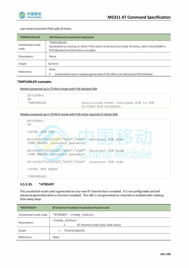
M5311 AT Command Specification
143 /192
user enters incorrect PUK code 10 times.
*MSMPUKBLKD SIM Blocked Unsolicited Indication
Unsolicited result code
*SMPUKBLKD Generated on startup or when PUK code is entered incorrectly 10 times, when the (U)SIM is PUK Blocked and therefore unusable.
Parameters None
Scope Generic
Reference Note
• Unsolicited event is always generated if the SIM is (or becomes) PUK blocked. *SMPUKBLKD examples
Modem powered up in CFUN=0 mode with PUK blocked SIM
AT+CFUN=1
OK
*SMPUKBLKD Unsolicited Event indicates SIM is PUK
blocked and unusable.
Modem powered up in CFUN=0 mode with PUK entry required (3 retries left)
AT+CFUN=1
OK
+CPIN: SIM PUK
AT+CPIN=”33333333”,”0000”,”0000” Incorrect PUK code
+CME ERROR: incorrect password
AT+CPIN=”33333333”,”0000”,”0000” Incorrect PUK code
+CME ERROR: incorrect password
AT+CPIN=”33333333”,”0000”,”0000” Incorrect PUK code
+CPIN: NOT READY
*SMPUKBLKD
3.5.2.35. *ATREADY
This unsolicited result code is generated on any new AT channel that is enabled. It is not configurable and will always be generated when a channel is enabled. This URC is not generated on channels re-enabled after wakeup from deep sleep.
*MATREADY AT Channel Enabled Unsolicited Result Code
Unsolicited result code *ATREADY: <ready_status>
Parameters <ready_status>
1 AT channel ready (only valid value)
Scope o Channel Specific
Reference Note

M5311 AT Command Specification
144 /192
*ATREADY URC examples
(AT channel enabled)
*ATREADY: 1

M5311 AT Command Specification
145 /192
4. Network Related Proprietary AT Command Interface This chapter introduces the supported proprietary platform AT command set on M5311. We support single AT command. When executing the previous AT command is finished, the next AT command will be executed.
4.1. PDN Command
4.1.1 AT+EGACT Activate or deactivate a specified PDN context. There are three kinds of responses for both the activation requirement and the deactivation requirement. If the PDN context is active/inactive, “+EGACT=<cid>,<type>,<result>[,<activated_pdp_type>] OK” is returned immediately for activation/deactivation requirement. If not, “+EGACT=<cid> OK” is returned first and URC ”+EGACT=<cid>,<type>,<result>[,< activated_pdp_type>]” is reported for the activation/deactivation result latter. If any error occurs, such as invalid parameter(s), “ERROR” is returned immediately. In any case, activated_pdp_type only exists for the activation requirement. Besides, URC “+EGACT=<cid>,<type>” is reported when passive deactivation occurs. For the activation requirement, the format of the EGACT is “+EGACT=<op>,<pdp_type>,<apn>,<user_name>,<pwd>[,<bearer_type>[,<sim_id>]]”, while for the deactivation requirement, the format is “+EGACT=<op>,<cid>”. For the purpose of normalization, the format of EGACT is “+EGACT=<op>,<pdp_type/cid>[,<apn>,<user_name>,<pwd>[,<bearer_type>[,<sim_id>]]]”.
AT+EGACT Activate or deactivate a PDN context
Set command
AT+EGACT=<op>,<pdp_type/cid>[,<apn>,<user_name>,<pwd>[,<bearer_type>[,<sim_id>]]]
Response
• +EGACT=<cid>,<type>,<result>[,<activated_pdp_type>]
• OK
• +EGACT=<cid>
• OK
• ERROR
Parameters
• <op> integer type;
0 deactivation requirement
1 activation requirement
• <pdp_type/cid> integer type;
If <op> is 0, it is pdp_type. Otherwise, it is cid. pdp_type:
It is the pdp_type wanted to activate.
1 IPv4
2 IPv6
3 IPv4v6
4 Non-IP
• <cid> It is a numeric parameter specifying a particular PDP context. Here it should be equal to the <cid> returned by the activation

M5311 AT Command Specification
146 /192
response
• <apn> string type;It is the access point name which is mandatory for the activation requirement and should be omitted for the deactivation requirement.
• <user_name> string type; It is the user name for access to the IP network which is mandatory for the activation requirement and should be omitted for the deactivation requirement.
• <pwd>: string type; It is the password for access to the IP network which is mandatory for the activation requirement and should be omitted for the deactivation requirement.
• <bearer_type> integer type; It is the type of bearer wanted to activate which is optional for the activation requirement and should be omitted for the deactivation requirement.
1 NBIOT (Only NBIOT is supported currently)
• <sim_id>: integer type; It is the id of the SIM Card wanted to use which is optional for the activation requirement and should be omitted for the deactivation requirement.
1 SIM Card 1 (Only SIM Card 1 is supported currently).
• <cid>: integer type;
It is a numeric parameter specifying a particular PDP context.
• <type>: integer type;
0 Result/URC for deactivation requirement
1 Result/URC for activation requirement
2 URC for passive deactivation
• <result> integer type;
0 failure
1 success
• <activated_pdp_type>: integer type; It is the pdp_type actually activated.
1 IPv4
2 IPv6
3 IPv4v6
4 Non-IP
Reference Note
• This command name is temporary and may be changed in the later release.
+EGACT Examples
AT+EGACT=1,1,”apn_example”,”username_example”,”password_example” Activate a
PDN context
+EGACT=1

M5311 AT Command Specification
147 /192
OK Return OK immediately for no error
+EGACT=1,1,1,1 Notify activation result via URC
AT+EGACT=0,1 Deactivate a PDN context
+EGACT=1
OK Return OK immediately for no error
+EGACT=1,0,1 Notify deactivation result via URC
4.2. Network Command
4.2.1 AT+PING
This command sends an ICMP packet to the specified host address. AT+PING initiates the sending of a PING packet to the specified address. This will either cause a packet to be returned if the remote system is connected and responding to PING packets, or no response will be received. A maximum of 1 ping attempts will be tried. If none of the packets receive a response within the timeout period, an error will be raised.
AT+PING Test IP network connectivity to a remote host
Set command
AT+PING=<remote addr>[,<p_size>[,<timeout>[,<p_count>[,<type>]]]]
Response
• OK
• ERROR
Unsolicited result code
Display test result, such as:
+PING: <remote addr>,,<rtt>
+PINGERR: 1
Parameters
• <remote addr> address of system sending the message, IPv4: A dot notation IP address
• <p_size> integer size in bytes of echo packet payload. Range of 8-1460, Default 64
• <timeout> ping timeout, if this ping packet ackownledge received timeout, concidering it as a lost packet.
• <p_count> integer, number of packet to send. Default 3
• <type> integer, ipv4 or ipv6, 0 - ipv4, 1 - ipv6. Default 0
• <rtt> ping latency result
Reference Note
+PING Examples
at+ping=183.232.231.173,16,8000,10 //start ping
OK
+PING: 183.232.231.173,,3190 //ping result of first ping packet
+PING: 183.232.231.173,,3700
+PING: 183.232.231.173,,1520
+PING: 183.232.231.173,,1500
+PING: 183.232.231.173,,1510

M5311 AT Command Specification
148 /192
+PING: 183.232.231.173,,1510
+PING: 183.232.231.173,,1460
+PING: 183.232.231.173,,1120
+PING: 183.232.231.173,,1750
+PING: 183.232.231.173,,1710
--- 183.232.231.173 ping statistics --- //pings result
10 packets transmitted, 10 received, 0% packet loss
rtt min/avg/max = 1120/1897/3700
4.2.1 AT+DNSSER This command set DNS server address, it takes effect following the issuance of ‘OK’ result code with the current
command line. The DNS server address will effect on all DNS associated network services, such as
MQTT/HTTP/TLS/OneNET, it very important to make sure that the dns servers address is valid.
AT+ DNSSER set DNS server address
Test Command
AT+DNSSER=?
Response
• +DNSSER: <server_ip>,(0-1),(0-1)
• OK
• ERROR
Read command
AT+DNSSER?
Response
• +DNSSER: <dns_id>,<server_ip>
• OK
Execution command
AT+DNSSER=<server_ip>[,<dns_id>[,<iptype>]]
Response
• OK
• ERROR
Parameters
• <server_ip> string, DNS server address. Default DNS server address is:
119.29.29.29
114.114.114.114
• <dns_id> integer, DNS ID. Default 0.
• 0 preferred server address.
• 1 secondary server address.
If preferred server address is invalid, it will request Secondary.
• <ip_typet> integer, type of the DNS return ip address. Default 0
• 0 IPv4
• 1 IPv6
Scope Generic
Reference Note
+DNSSER Examples
AT+DNSSER="180.76.76.76",0,0 //Set preferred ipv4 server address.
OK

M5311 AT Command Specification
149 /192
AT+DNSSER="223.5.5.5",1,0 //Set secondary ipv4 server address.
OK
AT+DNSSER?
+DNSSER: 0,180.76.76.76
+DNSSER: 1,223.5.5.5
OK
4.2.2 AT+CMDNS This command send a DNS request to DNS server, and return the parsed ip address.
AT+CMDNS Send a DNS request
Set command
AT+CMDNS =<domain>[,<ip_type>[,<server_ip>]]
Response
• OK
• ERROR
Unsolicited result code
+CMDNS: <ip_address>
Parameters
• < domain> string, domain name.
• <ip_typet> integer, type of the DNS return ip address.default 0
• 0 IPv4
• 1 IPv6
• <server_ip> string, DNS server address, Only effective once.
• <ip_address> A dot notation IP address
Reference Note
+ CMDNS Examples
AT+EGACT=1,1,"cmiot","","" //activate pdn connection
OK
+IP: 10.212.231.112
+EGACT:1,1,1,1
AT+CMDNS= "iot.10086.cn"
// request iot.10086.cn DNS service
OK
+CMDNS: 183.230.40.127 //receive ip address
4.2.3 AT+IPSTART
This command creates a TCP or UDP socket and connect to remote server.
AT+IPSTART Creates a TCP or UDP socket
Set command AT+IPSTART=<sockid>,<type>,<addr>,<port>[,<cid>[,<domian>[,<protocol>]]]

M5311 AT Command Specification
150 /192
Response
• OK
• Or ERROR
Parameters
• <sockid> integer, socket channel number, 0-5
• <type> string
“TCP” TCP socket
“UDP” UDP socket
“RAW” RAW socket
• <addr> string, remote address
• <port> integer, remote port
• <cid> integer, PDP context ID, AT+EGACT response.
• <domain> integer, default 2
2 IPv4
10 IPv6
• <protocol> number of packet to send, default 0, only 0 supported now.
0 IP
1 ICMP
6 TCP
17 UDP
Reference Note
+IPSTART Examples
AT+EGACT=1,1,"cmiot","","" //activate pdn connection
OK
+IP: 10.212.231.112
+EGACT:1,1,1,1
at+ipstart=0,"TCP","47.93.217.230",2008
//setup and connect to 47.93.217.230:2008
OK
CONNECT OK //connect to 47.93.217.230:2008 OK
+IPRD: 0,15,hello, CMCC IOT //receive 37 bytes data “hello, CMCC IOT” from 47.93.217.230:2008
4.2.4 AT+IPLPORT
This command used to bind to local port. Used chiefly set local port.
AT+IPLPORT Bind local address and local port
Set command
AT+IPLPORT=<socket_id>,<local_port>
Response
• OK
• ERROR

M5311 AT Command Specification
151 /192
Parameters • <socket_id> integer, socket id, refer to AT+IPSTART
• <local_port> integer, local port.
Reference Note
4.2.5 AT+IPSEND
This command used to send data to network. The response “OK” just mean the ATCMD format is right and data have been put to socket, waiting for send.
AT+IPSEND Send data to remote via socket
Set command
TCP : AT+IPSEND=<socket_id>,[<data_len>],<data>[,<pri_flag>]
UDP : AT+IPSEND=<socket_id>,[<data_len>],<data>[,<addr>,<port>[,<pri_flag>]]
Response
• +IPSEND: <socket_id>,<sent_len>
• OK
• ERROR
Parameters
• <socket_id> integer, socket id, AT+ESOC’s response.
• <data_len> integer, length of data. Default 0.
• <data> string, raw_data. When <data_len> is greater than 0, <data> is hex format string , else if <data_len> set to 0 or omit, <data> is normal string.
• <addr> string, remote address, only valid in UDP socket.
• <port> integer, remote port, only valid in UDP socket.
• <pri_flag> integer, priority flag.
0 IPTOS reliability, default
1 IPTOS lowdelay
2 IPTOS hroughput
3 IPTOS lowcost
• <sent_len> integer, actual sent-out data length
Reference Note
+IPSEND Examples
at+ipsend=0,0,"this is normal string" //send normal string
+IPSEND: 0,21
OK
at+ipsend=0,,"this is another normal string" //send normal string
+IPSEND: 0,29
OK
at+ipsend=0,2,"3132" //send hex string
+IPSEND: 0,2
OK
For TCP socket:
at+ipsend=0,0,"this is normal string",1 //send normal string with
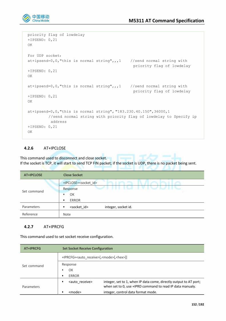
M5311 AT Command Specification
152 /192
priority flag of lowdelay
+IPSEND: 0,21
OK
For UDP socket:
at+ipsend=0,0,"this is normal string",,,1 //send normal string with
priority flag of lowdelay
+IPSEND: 0,21
OK
at+ipsend=0,0,"this is normal string",,,1 //send normal string with
priority flag of lowdelay
+IPSEND: 0,21
OK
at+ipsend=0,0,"this is normal string", "183.230.40.150",36000,1
//send normal string with priority flag of lowdelay to Specify ip
address
+IPSEND: 0,21
OK
4.2.6 AT+IPCLOSE
This command used to disconnect and close socket. If the socket is TCP, it will start to send TCP FIN packet; if the socket is UDP, there is no packet being sent.
AT+IPCLOSE Close Socket
Set command
+IPCLOSE=<socket_id>
Response
• OK
• ERROR
Parameters • <socket_id> integer, socket id.
Reference Note
4.2.7 AT+IPRCFG
This command used to set socket receive configuration.
AT+IPRCFG Set Socket Receive Configuration
Set command
+IPRCFG=<auto_receive>[,<mode>[,<hex>]]
Response
• OK
• ERROR
Parameters
• <auto_receive> integer, set to 1, when IP data come, directly output to AT port; when set to 0, use +IPRD command to read IP data manualy.
• <mode> integer, control data format mode.
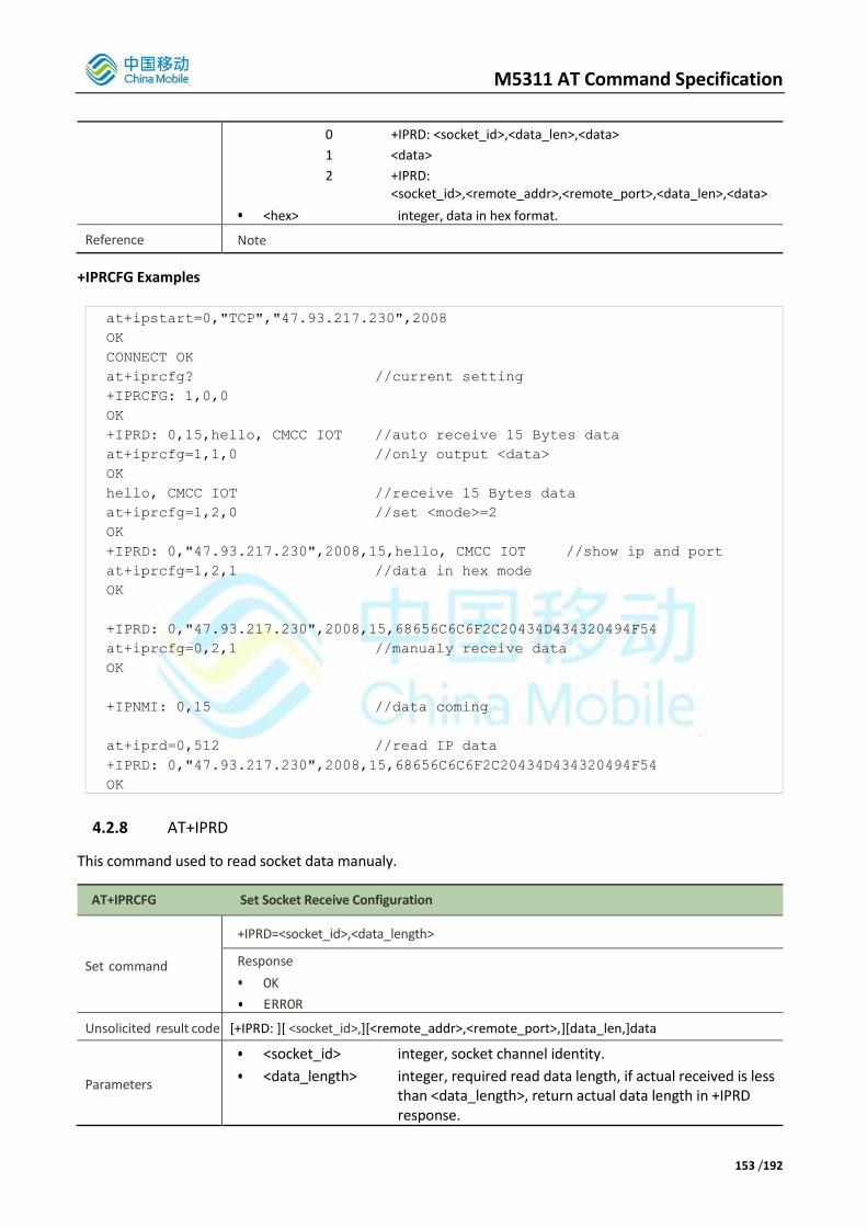
M5311 AT Command Specification
153 /192
0 +IPRD: <socket_id>,<data_len>,<data>
1 <data>
2 +IPRD: <socket_id>,<remote_addr>,<remote_port>,<data_len>,<data>
• <hex> integer, data in hex format.
Reference Note
+IPRCFG Examples
at+ipstart=0,"TCP","47.93.217.230",2008
OK
CONNECT OK
at+iprcfg? //current setting
+IPRCFG: 1,0,0
OK
+IPRD: 0,15,hello, CMCC IOT //auto receive 15 Bytes data
at+iprcfg=1,1,0 //only output <data>
OK
hello, CMCC IOT //receive 15 Bytes data
at+iprcfg=1,2,0 //set <mode>=2
OK
+IPRD: 0,"47.93.217.230",2008,15,hello, CMCC IOT //show ip and port
at+iprcfg=1,2,1 //data in hex mode
OK
+IPRD: 0,"47.93.217.230",2008,15,68656C6C6F2C20434D434320494F54
at+iprcfg=0,2,1 //manualy receive data
OK
+IPNMI: 0,15 //data coming
at+iprd=0,512 //read IP data
+IPRD: 0,"47.93.217.230",2008,15,68656C6C6F2C20434D434320494F54
OK
4.2.8 AT+IPRD This command used to read socket data manualy.
AT+IPRCFG Set Socket Receive Configuration
Set command
+IPRD=<socket_id>,<data_length>
Response
• OK
• ERROR
Unsolicited result code [+IPRD: ][ <socket_id>,][<remote_addr>,<remote_port>,][data_len,]data
Parameters
• <socket_id> integer, socket channel identity.
• <data_length> integer, required read data length, if actual received is less than <data_length>, return actual data length in +IPRD response.

M5311 AT Command Specification
154 /192
Reference Response format refers to +IPRCFG command
4.2.9 +IPNMI Indicated there is received some data from network.
+IPNMI Socket data from network URC
Unsolicited result code +IPNMI: <socket_id>,<data_len>
Parameters
• <socket_id> integer, socket channel id.
• <data_len> integer, length of data incoming. If read length is less than <data_length> using +IPRD command, the remaining data will unsolicited after some seconds if not read anymore.
Reference Note
4.2.10 AT+IPKPA Set TCP socket keepalive parameters.
AT+IPKPA TCP Keepalive Configuration
Set command
AT+IPKPA=<socket_id>,<keepalive>,<keep_idle>,<keep_interval>,<keep_cnt>
Response
• OK
• ERROR
Read command
AT+IPKPA=<socket_id>
Response
• +IPKPA: <socket_id>,<keepalive>,<keep_idle>,<keep_interval>,<keep_cnt>
• OK
Parameters
• <socket_id> integer, socket channel identity.
• <keepalive> integer, enable/disable keepalive mode, default 0.
• <keep_idle> integer, idle time to trigger keepalive mechanism in s, default 120
• <keep_interval> integer, check alive interval in s, default 30.
• <keep_cnt> integer, maximmum check alive times if last check fail, default 9
Reference Note
4.2.11 AT+IPSACK Query Socket send and read bytes statistics.
AT+IPSACK Query socket statistics such as tx/rx length and tcp unacked bytes
Read command
AT+IPSACK=<socket_id>
Response
• <sent>,<received>[,<rx_buf_left>,<unsent>,<unacked>]
• OK
• ERROR

M5311 AT Command Specification
155 /192
Parameters
• <socket_id> integer, socket channel identity.
• <sent> integer, total sent bytes of specified socket.
• <received> integer, total received bytes of specified socket
• <rx_buf_left> integer, toal sent buffer left, default max 4KB. Only valid in TCP socket
• <unsent> integer, data not sent. Only valid in TCP socket
• <unacked> integer, data send out and ack not received from remote host. Only valid in TCP socket
Reference Note
4.2.12 AT+IPSTATUS Query Socket connection status.
AT+IPSTATUS Query socket Status
Read command
AT+IPSTATUS=<socket_id>
Response
• <socket_id>,<type>,<addr>,<port>,<stat>
• OK
• ERROR
Parameters
• <socket_id> integer, socket channel identity.
• <type> string, TCP or UDP.
• <addr> string, remote address
• <port> integer, remote port
• <stat> string
"IP INITIAL"
"IP START"
"IP CONFIG"
"PDP ACT"
"IP STATUS"
"CONNECTING"
"CONNECTED"
"CLOSING"
"CLOSED"
"PDP DEACT"
"CONNECT FAIL"
Reference Note
4.2.13 Create a TCP socket example
AT+EGACT=1,1,"apn","user_name","pwd“ //activate apn
+EGACT=<cid>,1,1,1
OK
at+ipstart=0,"TCP","47.93.217.230",2008 //connect to 47.93.217.230:2008
OK

M5311 AT Command Specification
156 /192
CONNECT OK //tcp connect ok
+IPRD: 0,38, //receive 38 Bytes data from tcp server
223.104.255.176:44520 CONNECTED OK
at+ipstatus=0
+IPSTATUS: 0,"TCP","47.93.217.230",2008,"CONNECTED"
OK //query tcp/ip channel 0 status
at+ipsend=0,0,"1233",1 //send 4 bytes data in text format with
//lowdelay priority
+IPSEND: 0,4
OK
at+ipsend=0,2,"1233" //send 2 bytes data in hex format
+IPSEND: 0,2
OK
at+ipsack=0 //check server tcp-acked state
+IPSACK: 6,38,4096,0,0
OK
at+ipsend=0,0,"0123456789012345678901234567890123456789012345678901234567890
123456789012345678901234567890123456789012345678901234567890123456789012345
678901234567890123456789012345678901234567890123456789012345678901234567890
123456789012345678901234567890123456789012345678901234567890123456789012345
678901234567890123456789012345678901234567890123456789012345678901234567890
123456789012345678901234567890123456789012345678901234567890123456789012345
678901234567890123456789012345678901234567890123456789012345678$"
//send 500 bytes in text format
+IPSEND: 0,500 //send 500 Bytes packet to tcp buffer success
OK
at+ipsack=0 //check remote acked state, 500Bytes unack
+IPSACK: 506,38,3596,0,500
OK
at+ipsack=0 //check again
+IPSACK: 506,38,4096,0,0 // remote received this packet confirmed
OK
+IPRD: 0,9,123456789 //receive 9 bytes data
at+ipstatus=0 //check current connection status
+IPSTATUS: 0,"TCP","47.93.217.230",2008,"CONNECTED"
OK
at+ipclose=0 //close socket
OK
at+ipstatus=0 //check current connection status
+IPSTATUS: 0,"","",0,""

M5311 AT Command Specification
157 /192
OK
4.2.14 Create a UDP socket example
AT+EGACT=1,1,"apn","user_name","pwd“ //activate apn
+EGACT=<cid>,1,1,1
OK
at+ipstart=0,"UDP","47.93.217.230",2008 //create udp socket
OK
at+ipstatus=0 //udp always in connected state
+IPSTATUS: 0,"UDP","47.93.217.230",2008,"CONNECTED"
OK
at+ipsend=0,0,"1233",,1 //send 4 bytes udp data to 47.93.217.230:2008
//with lowdelay priority
+IPSEND: 0,4
OK
at+ipsend=0,2,"1233" //send 2 bytes udp data to 47.93.217.230:2008
+IPSEND: 0,2
OK
at+ipsend=0,0,"1233","183.230.40.150",36000,1
//send 4 bytes udp data to specified address
//with lowdelay priority
+IPSEND: 0,4
OK
at+ipsend=0,0,"1233","47.93.217.230",2008
//send 4 bytes udp data to specified address
+IPSEND: 0,4
OK
+IPRD: 0,11,fffffffffff //received 11 bytes data
at+ipsack=0
+IPSACK: 40,11
OK
at+iprcfg=1,2,0 //set receive mode to show remote address
OK
+IPRD: 0,"47.93.217.230",2008,5,hello
// show remote address when receiving data
at+ipclose=0
OK
at+ipstatus=0

M5311 AT Command Specification
158 /192
+IPSTATUS: 0,"","",0,""
OK
4.3. MQTT Command
4.3.1 AT+MQTTCFG This command is used to config the MQTT client
AT+MQTTCFG Config the Client
Set command
AT+MQTTCFG=<server>,<port>,<id>,<keepAlive>,[<user>],[<passwd>],<clean>,<encrypt>
Response
• OK
Parameters
• <server> string, MQTT server IP address
• <port> string, MQTT server port
• <id> string, client ID, should be unique
• <cmdtimeout> integer, ack should be received during the interval
• <keepAlive> integer, keep alive interval (s)
• <user> string, user name
• <passwd> string, password
• <clean> integer, clean session(0-1)
• <encrypt> integer, 0 : TCP , 1 : SSl
Reference Note if encrypt =1 ,write the CA in flash before using
+MQTTCFG Examples
AT+MQTTCFG=183.230.40.39,6002,4069959,15,75829,
IIOu0oFUg1guk20ornTK1uzAcnM=,1,0
OK
4.3.2 AT+MQTTOPEN This command is used to send MQTT connection packet.
AT+MQTTOPEN Send Connection Packet
Set command
AT+MQTTOPEN=<usrFlag>,<pwdFlag>,<willFlag>,[<willRetain>,<willQos>,<will-topic>,<will-mesg>]
Response
• OK
• ERROR
Unsolicited result code +MQTTOPEN: <connack_rc>,<sessionPresent>
Parameters
• <usrFlag> integer, weather to use username (0-1)
• <pwdFlag > integer, weather to use pwdFlag (0-1)
• <willFlag> integer, weather to set willmsg (0-1)

M5311 AT Command Specification
159 /192
• <willRetain> interger, retained flag(0-1)
• <willQos> integer, message Qos(0-2)
• <will-topic> string, topic name of will
• <will-mesg> string, message of will
Reference Note
+MQTTOPEN Examples
AT+MQTTOPEN=1,1,0
+MQTTOPEN: OK
AT+MQTTOPEN=1,1,1,1,1,mywill,bye
+MQTTCONACK: FAIL
4.3.3 AT+MQTTSTAT This command is used to query MQTT client’s state.
AT+MQTTSTAT Query MQTT Client’s State
Query command
AT+MQTTSTAT?
Response
• +MQTTSTAT:<stat>
• OK
• ERROR
Parameters
• <stat>
0 UNINITIALED
1 INITIALED
2 DISCONNECTED
3 CONNECTING
4 RECONNECTING
5 CONNECTED
Reference Note
4.3.4 AT+MQTTSUB This command is used to send MQTT subscribe packet.
AT+MQTTSUB Send MQTT Subscribe Packet
Set command
AT+MQTTSUB=<topic>,<Qos>,<index>
Response
• OK
• ERROR
Unsolicited result code +MQTTSUBACK:<packet id>,<qos>,<topic name>
Parameters • <topic> string, topic of subscribe message
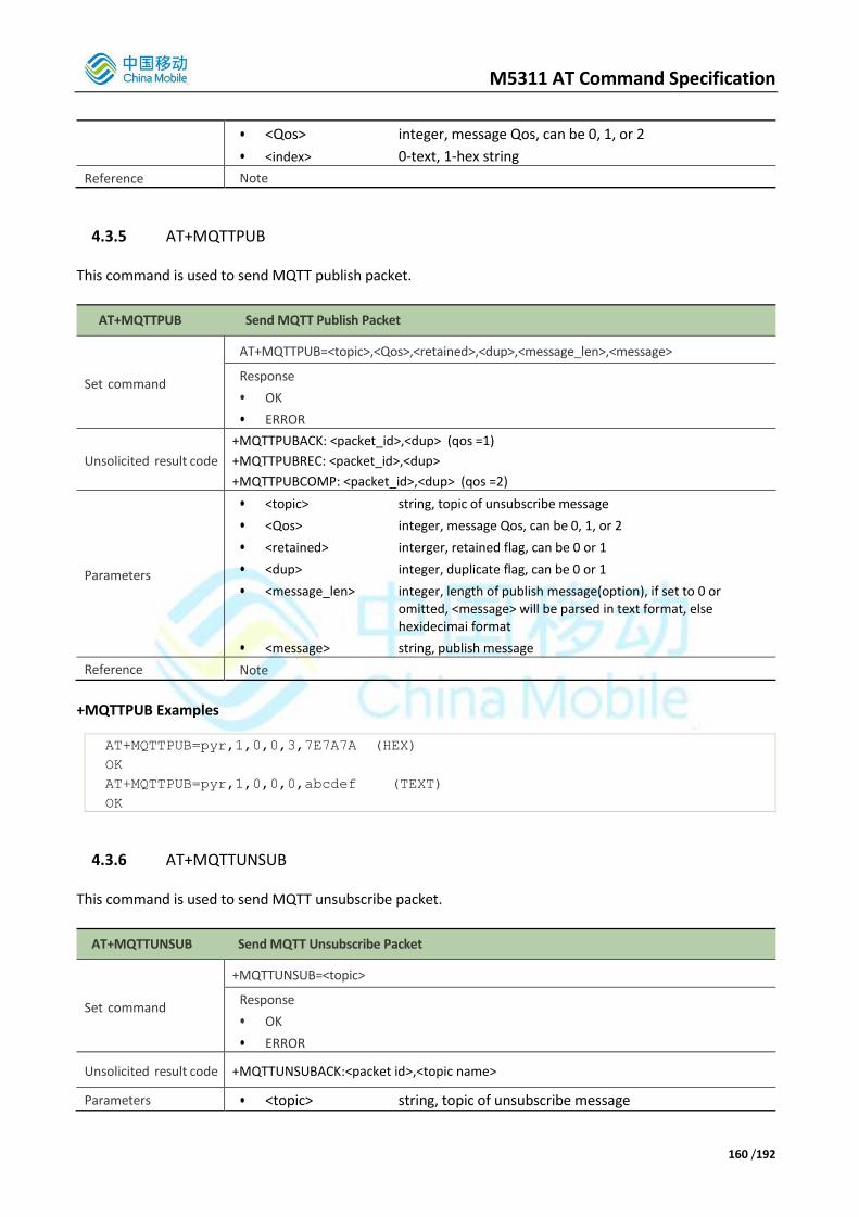
M5311 AT Command Specification
160 /192
• <Qos> integer, message Qos, can be 0, 1, or 2
• <index> 0-text, 1-hex string
Reference Note
4.3.5 AT+MQTTPUB This command is used to send MQTT publish packet.
AT+MQTTPUB Send MQTT Publish Packet
Set command
AT+MQTTPUB=<topic>,<Qos>,<retained>,<dup>,<message_len>,<message>
Response
• OK
• ERROR
Unsolicited result code
+MQTTPUBACK: <packet_id>,<dup> (qos =1)
+MQTTPUBREC: <packet_id>,<dup>
+MQTTPUBCOMP: <packet_id>,<dup> (qos =2)
Parameters
• <topic> string, topic of unsubscribe message
• <Qos> integer, message Qos, can be 0, 1, or 2
• <retained> interger, retained flag, can be 0 or 1
• <dup> integer, duplicate flag, can be 0 or 1
• <message_len> integer, length of publish message(option), if set to 0 or omitted, <message> will be parsed in text format, else hexidecimai format
• <message> string, publish message
Reference Note
+MQTTPUB Examples
AT+MQTTPUB=pyr,1,0,0,3,7E7A7A (HEX)
OK
AT+MQTTPUB=pyr,1,0,0,0,abcdef (TEXT)
OK
4.3.6 AT+MQTTUNSUB This command is used to send MQTT unsubscribe packet.
AT+MQTTUNSUB Send MQTT Unsubscribe Packet
Set command
+MQTTUNSUB=<topic>
Response
• OK
• ERROR
Unsolicited result code +MQTTUNSUBACK:<packet id>,<topic name>
Parameters • <topic> string, topic of unsubscribe message
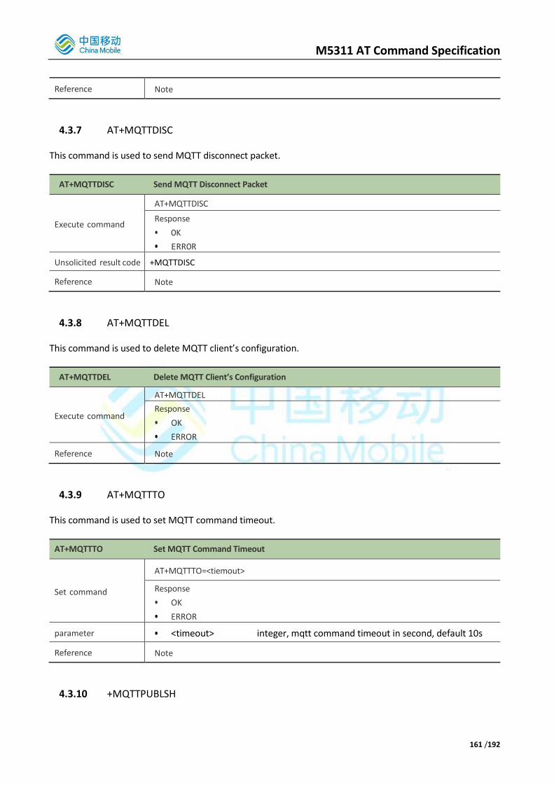
M5311 AT Command Specification
161 /192
Reference Note
4.3.7 AT+MQTTDISC This command is used to send MQTT disconnect packet.
AT+MQTTDISC Send MQTT Disconnect Packet
Execute command
AT+MQTTDISC
Response
• OK
• ERROR
Unsolicited result code +MQTTDISC
Reference Note
4.3.8 AT+MQTTDEL This command is used to delete MQTT client’s configuration.
AT+MQTTDEL Delete MQTT Client’s Configuration
Execute command
AT+MQTTDEL
Response
• OK
• ERROR
Reference Note
4.3.9 AT+MQTTTO This command is used to set MQTT command timeout.
AT+MQTTTO Set MQTT Command Timeout
Set command
AT+MQTTTO=<tiemout>
Response
• OK
• ERROR
parameter • <timeout> integer, mqtt command timeout in second, default 10s
Reference Note
4.3.10 +MQTTPUBLSH

M5311 AT Command Specification
162 /192
This urc is used to receive MQTT publish packet.
+MQTTPUBLISH Receive MQTT Publish Packet
Unsolicited result code +MQTTPUBLISH: <dup>,<qos>,<retained>,<packet_id>,[<message_len>],<message>
Parameters
• <dup> integer, duplicate flag, can be 0 or 1
• <qos> integer, message Qos, can be 0, 1, or 2
• <retained> integer, retained flag, can be 0 or 1
• <packet_id> integer, the id of current packet
• <message_len> integer, length of publish message
• <message> string, publish message
Reference Note
4.3.11 +MQTTTO This urc is used to indicate timeout when user send a MQTT command without ACK during the setting time .
+MQTTTO Indicate Time Out
Unsolicited result code +MQTTTO: <cmd>
Parameters
• <cmd> integer, mqtt command type
1 connect timeout 2 publish timeout 3 subcribe timeout 4 unsubcribe timeout 5 ping timeout 6 unkown timeout type
Reference Note
4.4. HTTP/HTTPS Command
4.4.1 AT+HTTPCREATE
This command is used to create an HTTP/HTTPS client instance. If <host> is start with “https://” , MT will create an HTTPS client.
AT+HTTPCREATE Create an HTTP/HTTPS Client instance
Set command
AT+HTTPCREATE=<host>[,<auth_user>,<auth_passwd>]
Response
• +HTTPCREATE: <httpclient_id>
• OK
• ERROR
Parameters
• <host> http server host
• <auth_user> authorization name [option]
• <auth_passwd> authorization password [option]
• <httpclient_id> indicator a http client instance
All option parameter should be exist or not exist in one command

M5311 AT Command Specification
163 /192
Reference Note
4.4.2 AT+HTTPCFG
This command is used to configure the https instance.http don’t need configuration.
AT+HTTPCFG Config an HTTPS Client instance
Set command
AT+HTTPCFG= <httpclient_id>,<type>[,<certificate>[,<encode_method>]]
Response
• +HTTPCFG: <httpclient_id>,<type>[,<length>]
• OK
• ERROR
Unsolicited result code <certificate>
Parameters
• <httpclient_id> the indicator of http client instance created by the AT+HTTPCREATE command.
• <type>
1 https server_cert
2 https client_cert
3 https client_pk
• <certificate> certificate
• <length> the certificate length
• <encode_method> integer, it is the encoded method used for <certificate>. 0 or NULL is for string encoding and it is the default value which can be omitted, 1 is for hex encoding. [option]
Reference
Note:
It must create httpclient instance first. If only input httpclient_id and type,UE will response current type cert information like:
+HTTPCFG:0,1,1306 -----BEGIN CERTIFICATE-----
...
... -----END CERTIFICATE-----
4.4.3 AT+HTTPHEADER
This command is used to set http/https header information.
AT+HTTPHEADER Config an HTTP/HTTPS Client Header
Set command
AT+HTTPHEADER= <httpclient_id>[,<header>[,<encode_method>]]
Response
• +HTTPHEADER: <httpclient_id>[,<length>]
• OK
• ERROR
Unsolicited result code <header>
Parameters • <httpclient_id> the indicator of http client instance created by the
AT+HTTPCREATE command.

M5311 AT Command Specification
164 /192
• <header> header
• <length> the header length
• <encode_method>: integer, it is the encoded method used for < header >. 0 or NULL is for string encoding and it is the default value which can be omitted, 1 is for hex encoding. [option]
Reference
Note:
• if only input httpclient_id,the UE will return header information the header MAX size supported is 512 bytes
+HTTPHEADER example:
AT+HTTPHEADER=0,6170692D6B65793A4A4459694B794B6669344934734F4657654A73493453
3343626C303D0d0a,1
Or
AT+HTTPHEADER=0,"api-key:JDYiKyKfi4I4sOFWeJsI4S3Cbl0=\r\n",0 //set header
OK
AT+HTTPHEADER=0 //query header
+HTTPHEADER:0,38
OK
api-key:JDYiKyKfi4I4sOFWeJsI4S3Cbl0=
AT+HTTPHEADER=0,”” //clear header
Or
AT+HTTPHEADER=0, //clear header
OK
AT+HTTPHEADER=0 //header is NULL
OK
4.4.4 AT+HTTPCONTENT
This command is used to set http/https content information
AT+HTTPCONTENT Config an HTTP/HTTPS Client Content
Set command
AT+HTTPCONTENT= <httpclient_id>[,<content_string>[,<encode_method>]]
Response
• +HTTPCONTENT: <httpclient_id>[,<length>]
• OK
• ERROR
Unsolicited result code <content_string>
Parameters
• <httpclient_id> the indicator of http client instance created by the AT+HTTPCREATE command.
• <content_string> content_string
• <length> the content length
• <encode_method>: integer, it is the encoded method used for <content_string>. 0 or NULL is for string encoding and it is the default value which can be omitted, 1 is for hex encoding. [option]
Reference Note
• if only input httpclient_id,the UE will return content information
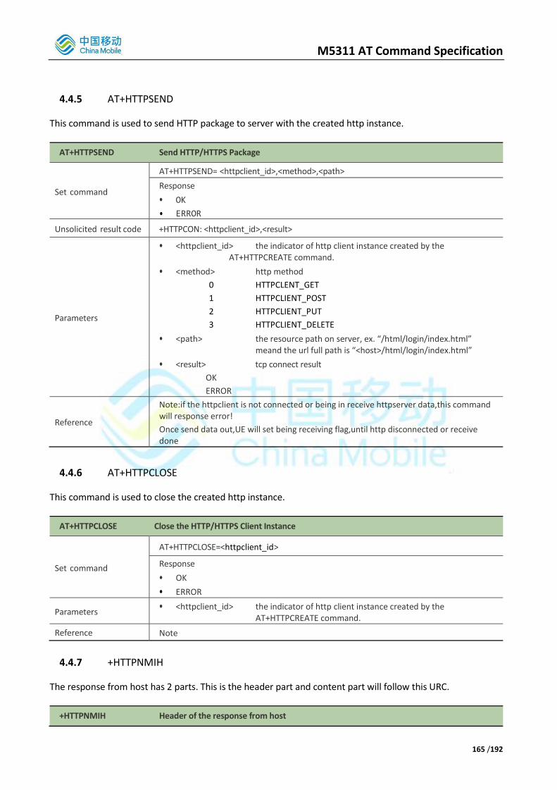
M5311 AT Command Specification
165 /192
4.4.5 AT+HTTPSEND
This command is used to send HTTP package to server with the created http instance.
AT+HTTPSEND Send HTTP/HTTPS Package
Set command
AT+HTTPSEND= <httpclient_id>,<method>,<path>
Response
• OK
• ERROR
Unsolicited result code +HTTPCON: <httpclient_id>,<result>
Parameters
• <httpclient_id> the indicator of http client instance created by the AT+HTTPCREATE command.
• <method> http method
0 HTTPCLENT_GET
1 HTTPCLIENT_POST
2 HTTPCLIENT_PUT
3 HTTPCLIENT_DELETE
• <path> the resource path on server, ex. “/html/login/index.html” meand the url full path is “<host>/html/login/index.html”
• <result> tcp connect result
OK
ERROR
Reference
Note:if the httpclient is not connected or being in receive httpserver data,this command will response error!
Once send data out,UE will set being receiving flag,until http disconnected or receive done
4.4.6 AT+HTTPCLOSE
This command is used to close the created http instance.
AT+HTTPCLOSE Close the HTTP/HTTPS Client Instance
Set command
AT+HTTPCLOSE=<httpclient_id>
Response
• OK
• ERROR
Parameters • <httpclient_id> the indicator of http client instance created by the
AT+HTTPCREATE command.
Reference Note
4.4.7 +HTTPNMIH
The response from host has 2 parts. This is the header part and content part will follow this URC.
+HTTPNMIH Header of the response from host
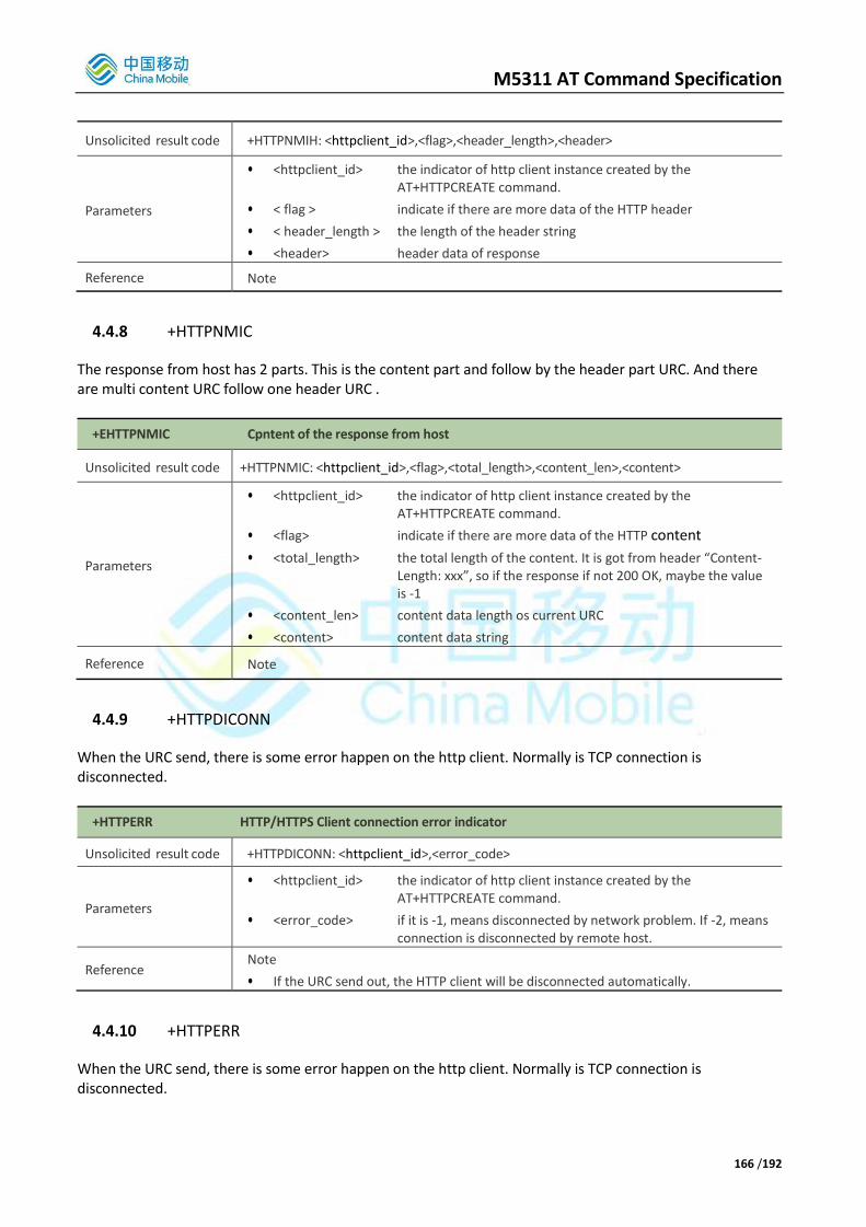
M5311 AT Command Specification
166 /192
Unsolicited result code +HTTPNMIH: <httpclient_id>,<flag>,<header_length>,<header>
Parameters
• <httpclient_id> the indicator of http client instance created by the AT+HTTPCREATE command.
• < flag > indicate if there are more data of the HTTP header
• < header_length > the length of the header string
• <header> header data of response
Reference Note
4.4.8 +HTTPNMIC
The response from host has 2 parts. This is the content part and follow by the header part URC. And there are multi content URC follow one header URC .
+EHTTPNMIC Cpntent of the response from host
Unsolicited result code +HTTPNMIC: <httpclient_id>,<flag>,<total_length>,<content_len>,<content>
Parameters
• <httpclient_id> the indicator of http client instance created by the AT+HTTPCREATE command.
• <flag> indicate if there are more data of the HTTP content
• <total_length> the total length of the content. It is got from header “Content-Length: xxx”, so if the response if not 200 OK, maybe the value is -1
• <content_len> content data length os current URC
• <content> content data string
Reference Note
4.4.9 +HTTPDICONN
When the URC send, there is some error happen on the http client. Normally is TCP connection is disconnected.
+HTTPERR HTTP/HTTPS Client connection error indicator
Unsolicited result code +HTTPDICONN: <httpclient_id>,<error_code>
Parameters
• <httpclient_id> the indicator of http client instance created by the AT+HTTPCREATE command.
• <error_code> if it is -1, means disconnected by network problem. If -2, means connection is disconnected by remote host.
Reference Note
• If the URC send out, the HTTP client will be disconnected automatically.
4.4.10 +HTTPERR
When the URC send, there is some error happen on the http client. Normally is TCP connection is disconnected.

M5311 AT Command Specification
167 /192
AT+HTTPERR HTTP/HTTPS Client connection error indicator
Unsolicited result code +HTTPERR=<httpclient_id>,<error_code>
Parameters • <httpclient_id> the indicator of http client instance created by the AT+HTTPCREATE command.
• <response_code> the http response code,not include 200
Reference Other
Proprietary commands if http receive response code not be 200,this URC will be output
4.4.11 HTTP/HTTPS Example Get Texts from HTTP server AT+HTTPCREATE="http://1i869245.iask.in:30686/"
+HTTPCREATE:0
OK
AT+HTTPSEND=0,0,"/"
OK
CONNECT OK
+HTTPNMIH:0,200,146,Server: Microsoft-IIS/5.1
X-Powered-By: ASP.NET
Content-Type: text/html
Accept-Ranges: bytes
ETag: "0c76c133e39c71:8f6"
Content-Length: 496
+HTTPNMIC:0,1,496,399
<html>
<head>
<meta http-equiv="Content-Type"
content="text/html; charset=gb2312">
<meta name="GENERATOR"
content="Microsoft FrontPage 4.0">
<meta name="ProgId"
content="FrontPage.Editor.Document"
>
<title>New Page 1</title>
</head>
<body>
<center>
<p>
</p>
<p><font face="宋体" size="2"> ?/font></p>
<p><font face="宋体" size="2"> <a
href
+HTTPNMIC:0,0,496,97
="http://www.zstel.com">HTTP://

M5311 AT Command Specification
168 /192
WWW.ZSTEL.COM</a></font></p>
</center>
</body>
</html>
+HTTPDICONN:0,-2
OK
POST Texts to HTTP server Header: api-key:JDYiKyKfi4I4sOFWeJsI4S3Cbl0=
Content-type:NULL(default)
Content-length:10
Content: {"RPM":22}
AT+HTTPCREATE="http://1i869245.iask.in:30686/"
+HTTPCREATE:0
OK
If use default encode(string),the AT Command is:
AT+HTTPHEADER=0,api-key:JDYiKyKfi4I4sOFWeJsI4S3Cbl0=\r\n,0
OK
AT+HTTPCONTENT=0,{"RPM":22},0
OK
If use HEX encode,the AT Command is:
AT+HTTPHEADER=0,6170692D6B65793A4A4459694B794B6669344934734F4657654A734934533
343626C303D0d0a,1
OK
AT+HTTPCONTENT=0,7B2252504D223A32327D,1
OK
AT+HTTPSEND=0,1,"/"
OK
CONNECT OK
...
Note:in <Header>,the “\r\n” is need,stand for a newline.if user want to input a char \r\n in defualt encode,an ‘\’should be add like this: AT+HTTPHEADER=0,api-key:JDYiKyKfi4I4sOFWeJsI4S3Cbl0=\\r\\n,0
AT+HTTPCONTENT=0,{"RPM":2\\r\\n2},0
Get a text file from an HTTPS server AT+HTTPCREATE=https://182.150.27.42:50090/
+HTTPCREATE:0
OK
AT+HTTPCFG=0,1,-----BEGIN CERTIFICATE-----
\r\nMIIDhzCCAm+gAwIBAgIBADANBgkqhkiG9w0BAQUFADA7MQswCQYDVQQGEwJOTDER\r\nMA8GA
1UEChMIUG9sYXJTU0wxGTAXBgNVBAMTEFBvbGFyU1NMIFRlc3QgQ0EwHhcN\r\nMTEwMjEyMTQ0ND
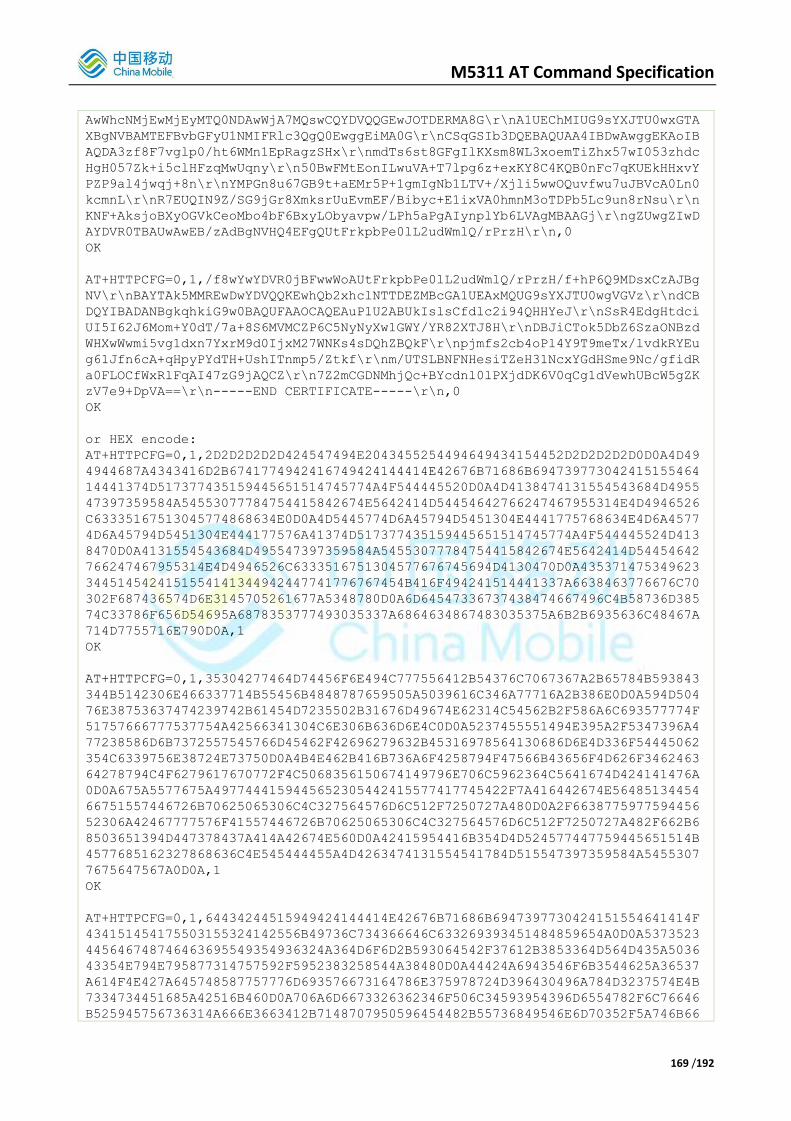
M5311 AT Command Specification
169 /192
AwWhcNMjEwMjEyMTQ0NDAwWjA7MQswCQYDVQQGEwJOTDERMA8G\r\nA1UEChMIUG9sYXJTU0wxGTA
XBgNVBAMTEFBvbGFyU1NMIFRlc3QgQ0EwggEiMA0G\r\nCSqGSIb3DQEBAQUAA4IBDwAwggEKAoIB
AQDA3zf8F7vglp0/ht6WMn1EpRagzSHx\r\nmdTs6st8GFgIlKXsm8WL3xoemTiZhx57wI053zhdc
HgH057Zk+i5clHFzqMwUqny\r\n50BwFMtEonILwuVA+T7lpg6z+exKY8C4KQB0nFc7qKUEkHHxvY
PZP9al4jwqj+8n\r\nYMPGn8u67GB9t+aEMr5P+1gmIgNb1LTV+/Xjli5wwOQuvfwu7uJBVcA0Ln0
kcmnL\r\nR7EUQIN9Z/SG9jGr8XmksrUuEvmEF/Bibyc+E1ixVA0hmnM3oTDPb5Lc9un8rNsu\r\n
KNF+AksjoBXyOGVkCeoMbo4bF6BxyLObyavpw/LPh5aPgAIynplYb6LVAgMBAAGj\r\ngZUwgZIwD
AYDVR0TBAUwAwEB/zAdBgNVHQ4EFgQUtFrkpbPe0lL2udWmlQ/rPrzH\r\n,0
OK
AT+HTTPCFG=0,1,/f8wYwYDVR0jBFwwWoAUtFrkpbPe0lL2udWmlQ/rPrzH/f+hP6Q9MDsxCzAJBg
NV\r\nBAYTAk5MMREwDwYDVQQKEwhQb2xhclNTTDEZMBcGA1UEAxMQUG9sYXJTU0wgVGVz\r\ndCB
DQYIBADANBgkqhkiG9w0BAQUFAAOCAQEAuP1U2ABUkIslsCfdlc2i94QHHYeJ\r\nSsR4EdgHtdci
UI5I62J6Mom+Y0dT/7a+8S6MVMCZP6C5NyNyXw1GWY/YR82XTJ8H\r\nDBJiCTok5DbZ6SzaONBzd
WHXwWwmi5vg1dxn7YxrM9d0IjxM27WNKs4sDQhZBQkF\r\npjmfs2cb4oPl4Y9T9meTx/lvdkRYEu
g61Jfn6cA+qHpyPYdTH+UshITnmp5/Ztkf\r\nm/UTSLBNFNHesiTZeH31NcxYGdHSme9Nc/gfidR
a0FLOCfWxRlFqAI47zG9jAQCZ\r\n7Z2mCGDNMhjQc+BYcdnl0lPXjdDK6V0qCg1dVewhUBcW5gZK
zV7e9+DpVA==\r\n-----END CERTIFICATE-----\r\n,0
OK
or HEX encode:
AT+HTTPCFG=0,1,2D2D2D2D2D424547494E2043455254494649434154452D2D2D2D2D0D0A4D49
4944687A4343416D2B6741774942416749424144414E42676B71686B694739773042415155464
14441374D517377435159445651514745774A4F544445520D0A4D4138474131554543684D4955
47397359584A54553077784754415842674E5642414D54454642766247467955314E4D4946526
C63335167513045774868634E0D0A4D5445774D6A45794D5451304E4441775768634E4D6A4577
4D6A45794D5451304E444177576A41374D517377435159445651514745774A4F544445524D413
8470D0A4131554543684D495547397359584A54553077784754415842674E5642414D54454642
766247467955314E4D4946526C6333516751304577676745694D4130470D0A435371475349623
3445145424151554141344942447741776767454B416F494241514441337A6638463776676C70
302F687436574D6E3145705261677A5348780D0A6D64547336737438474667496C4B58736D385
74C33786F656D54695A6878353777493035337A6864634867483035375A6B2B6935636C48467A
714D7755716E790D0A,1
OK
AT+HTTPCFG=0,1,35304277464D74456F6E494C777556412B54376C7067367A2B65784B593843
344B5142306E466337714B55456B4848787659505A5039616C346A77716A2B386E0D0A594D504
76E38753637474239742B61454D7235502B31676D49674E62314C54562B2F586A6C693577774F
51757666777537754A42566341304C6E306B636D6E4C0D0A5237455551494E395A2F5347396A4
77238586D6B7372557545766D45462F42696279632B45316978564130686D6E4D336F54445062
354C6339756E38724E73750D0A4B4E462B416B736A6F4258794F47566B43656F4D626F3462463
64278794C4F6279617670772F4C5068356150674149796E706C5962364C5641674D424141476A
0D0A675A5577675A4977444159445652305442415577417745422F7A416442674E56485134454
66751557446726B70625065306C4C327564576D6C512F7250727A480D0A2F6638775977594456
52306A42467777576F41557446726B70625065306C4C327564576D6C512F7250727A482F662B6
8503651394D447378437A414A42674E560D0A42415954416B354D4D524577447759445651514B
4577685162327868636C4E545444455A4D4263474131554541784D515547397359584A5455307
7675647567A0D0A,1
OK
AT+HTTPCFG=0,1,64434244515949424144414E42676B71686B6947397730424151554641414F
434151454175503155324142556B49736C734366646C633269393451484859654A0D0A5373523
445646748746463695549354936324A364D6F6D2B593064542F37612B3853364D564D435A5036
43354E794E795877314757592F5952383258544A38480D0A44424A6943546F6B3544625A36537
A614F4E427A645748587757776D693576673164786E375978724D396430496A784D3237574E4B
7334734451685A42516B460D0A706A6D6673326362346F506C34593954396D6554782F6C76646
B525945756736314A666E3663412B7148707950596454482B55736849546E6D70352F5A746B66

M5311 AT Command Specification
170 /192
0D0A6D2F5554534C424E464E48657369545A654833314E637859476448536D65394E632F67666
964526130464C4F43665778526C4671414934377A47396A4151435A0D0A375A326D4347444E4D
686A51632B425963646E6C306C50586A64444B3656307143673164566577685542635735675A4
B7A563765392B447056413D3D0D0A2D2D2D2D2D454E442043455254494649434154452D2D2D2D
2D0D0A,1
OK
AT+HTTPSEND=0,0,"/"
OK
CONNECT OK
+HTTPNMIH:0,200,224,Date: Mon, 09 Apr 2018 01:07:13 GMT
Server: Apache/2.4.27 (Win32) OpenSSL/1.0.2l
Last-Modified: Mon, 27 Nov 2017 01:57:39 GMT
ETag: "15c-55eed3a259fdb"
Accept-Ranges: bytes
Content-Length: 348
Content-Type: text/html
+HTTPNMIC:0,0,348,348 <!doctype html public "-//W3C//DTD HTML 4.0 Transitional//EN"> <html> <head> <title> Test </title> </head> <body> <H1>This is an example page for testing.</H1> <H2>This is an example page for testing.</H2> <H3>This is an example page for testing.</H3> <strong>This</strong> is an example page for testing. </body> </html>
+HTTPDICONN:0,-2
4.5. TLS Command
4.5.1. AT+TLSCFG
Configure TLS parameters. Multiple <type> and <value> groups are supported. When the TLS parameters are in use such as during TLS configuration, ERROR will be returned for this AT command. There are three <encode_type> supported which are string, hex and base64. String encoding uses escape character \ to express un-printable characters and \o00 and \xhh are supported. For example, 0x0D can be encoded as ‘\r’, \15 or \x0D. In hex encoding, the high four bits and the low four bits of character will be encoded as an ASCII character separately. For example, 0x0D will be encoded as 0x00 and 0x0D.
AT+TLSCFG Configure TLS Parameters
Set command AT+TLSCFG=<tid>,<type>,<value>[,<type>,<value>[,<type>,<value>[…]]]
Response

M5311 AT Command Specification
171 /192
• OK
• ERROR
Parameters
• <tid> integer, the identifier of the TLS connection to be created. Range 1 to 5.
• <type> integer, the type of the parameter to be configured.
• <value> interger, the value of the parameter to be configured.
Reference Note
parameter type
Value
mandatory Value type Value content
Default value
Server name 1 string Server name None Y
port 2 integer Port number 443 N
Socket type 3 interger 0,TCP 1,UDP(Not Support currently)
0 N
Authentication mode
4 integer 0,none 1,optinal 2,required
2 N
Debug Level 5 integer 0,no log 1-4,the bigger the value is, the more log will be generated.
0 N
Server CA certificate
6 Sub parameters
<size>,<more>,<certificate>,[,<encode_method>] <size>: interger, the size of the buffer to store the whole certificate. It should be the total size of the whole encoded certificate using <encode_method> and could be bigger than that. <more> integer, 1 means more certificate content will be inputted. The server CA cerfitiction configuration always ends by +TLSCFG with <more> of 0. <certificate>: string, the total or partial content of the encoded certificate with quotation marks. <encode_method>: integer, it is the encoded method used for <certificate>. 801 is for string encoding and it is the default value which can be omitted, 802 is for hex encoding. And 803 is for base64 encoding.
Null
If authentication mode is 2, it’s Y, otherwise, N
Client CA certificate
7 Sub parameters
Same as server CA certifocate Null
If client authentication is needed, it’s Y, otherwise, N
Client private key
8 Sub parameters
<size>,<more>,<private_key>,[,<encode_method>] <private_key>: the total or partial content od the encoded private key with quotation marks. Other parameters are the same as the ones for server CA certificate.
Null,
If client certificate is Y, it’s Y, otherwise, it should not be configured.
+TLSCFG Example
AT+TLSCFG=1,1,”182.150.27.42”,2,50090,3,0,4,2,5,2 //set server ip, port
OK
AT+TLSCFG=1,6,1344,1,” -----BEGIN CERTIFICATE-----\r\n MIIDhzCCAm+gAwIBAgIBADANBgkqhkiG9w0BAQUFADA7MQswCQYDVQQGEwJOTDER\r\n
MA8GA1UEChMIUG9sYXJTU0wxGTAXBgNVBAMTEFBvbGFyU1NMIFRlc3QgQ0EwHhcN\r\n
MTEwMjEyMTQ0NDAwWhcNMjEwMjEyMTQ0NDAwWjA7MQswCQYDVQQGEwJOTDERMA8G\r\n
A1UEChMIUG9sYXJTU0wxGTAXBgNVBAMTEFBvbGFyU1NMIFRlc3QgQ0EwggEiMA0G\r\n
CSqGSIb3DQEBAQUAA4IBDwAwggEKAoIBAQDA3zf8F7vglp0/ht6WMn1EpRagzSHx\r\n
mdTs6st8GFgIlKXsm8WL3xoemTiZhx57wI053zhdcHgH057Zk+i5clHFzqMwUqny\r\n

M5311 AT Command Specification
172 /192
50BwFMtEonILwuVA+T7lpg6z+exKY8C4KQB0nFc7qKUEkHHxvYPZP9al4jwqj+8n\r\n
YMPGn8u67GB9t+aEMr5P+1”
AT+TLSCFG=1,6,1344,1,“gmIgNb1LTV+/Xjli5wwOQuvfwu7uJBVcA0Ln0kcmnL\r\n R7EUQIN9Z/SG9jGr8XmksrUuEvmEF/Bibyc+E1ixVA0hmnM3oTDPb5Lc9un8rNsu\r\n
KNF+AksjoBXyOGVkCeoMbo4bF6BxyLObyavpw/LPh5aPgAIynplYb6LVAgMBAAGj\r\n
gZUwgZIwDAYDVR0TBAUwAwEB/zAdBgNVHQ4EFgQUtFrkpbPe0lL2udWmlQ/rPrzH\r\n
/f8wYwYDVR0jBFwwWoAUtFrkpbPe0lL2udWmlQ/rPrzH/f+hP6Q9MDsxCzAJBgNV\r\n
BAYTAk5MMREwDwYDVQQKEwhQb2xhclNTTDEZMBcGA1UEAxMQUG9sYXJTU0wgVGVz\r\n
dCBDQYIBADANBgkqhkiG9w0BAQUFAAOCAQEAuP1U2ABUkIslsCfdlc2i94QHHYeJ\r\n
SsR4EdgHtdciUI5I62J“
AT+TLSCFG=1,6,1344,0,“6Mom+Y0dT/7a+8S6MVMCZP6C5NyNyXw1GWY/YR82XTJ8H\r\n DBJiCTok5DbZ6SzaONBzdWHXwWwmi5vg1dxn7YxrM9d0IjxM27WNKs4sDQhZBQkF\r\n
pjmfs2cb4oPl4Y9T9meTx/lvdkRYEug61Jfn6cA+qHpyPYdTH+UshITnmp5/Ztkf\r\n
m/UTSLBNFNHesiTZeH31NcxYGdHSme9Nc/gfidRa0FLOCfWxRlFqAI47zG9jAQCZ\r\n
7Z2mCGDNMhjQc+BYcdnl0lPXjdDK6V0qCg1dVewhUBcW5gZKzV7e9+DpVA==\r\n
-----END CERTIFICATE-----” //set server’s CA OK
4.5.2. AT+TLSCONN
Create a TLS connection . a PDN context should be activated by +EGACT before using +TLSCONN. The result of TLS connection is returned by +TLSCONN URC if OK is returned for TLSCONN AT command.
AT+TLSCONN Create a TLS connection
Set command
AT+TLSCONN=<tid>,<cid>[,<time>]
Response
• OK
• ERROR
Unsolicited result code +TLSCONN: <tid>,<ret>
Parameters
• <tid> integer, the identifier of the TLS connection to be created. It should be the same as the one in +TLSCFG.
• <cid> integer, a specified particular PDP context ID returned by +EGACT
• <time> integer, the parameter of receive timeout, specified in seconds,
Default 60s.
• <ret> interger, it tells the result of the TLS connection. If the connection succeeds, it is 1, otherwise, it is the error code.
Reference Note
<ret> error code
<ret> Description
-1 TLS Parameters of tid has not configure
-21 Initialize RNG and the session data failed
-22 Loading cli_cert or Parse cli_cert private key failed
-23 Loading the CA root certificate failed
-240 Failed to get an IP address for the given hostname
-241 The connection to the given server/ port failed

M5311 AT Command Specification
173 /192
-25 SSL/TLS structure set failed
-3 Handshake or Certificate verification failed
-4 Connection timed out
+TLSCONN Example
AT+TLSCONN=1,1,60 create a TLS connection
OK
+TLSCONN: 1,1 return TLS connection result
4.5.3. AT+TLSCLOSE
Close a TLS connection indicated by <tid> and release all related resources. The result is returned by +TLSCLOSE URC if OK is returned for +TLSCLOSE AT command. If the TLS connection is not created before, ERROR will be returned.
AT+TLSCLOSE Close a TLS connection
Set command
AT+TLSCLOSE=<tid>
Response
• OK
• ERROR
Unsolicited result code +TLSCLOSE: <tid>,<ret>
Parameters
• <tid> integer, the identifier of the TLS connection to be created. It should be the same as the one in +TLSCFG
• <ret> interger, it tells the result of the TLS closure. If the closure succeeds, it is 1, If the closore failed, it is -1.
Reference Other
Proprietary commands Note
+TLSCONN Example
AT+TLSCLOSE=1 Close the TLS connection
OK
+TLSCLOSE: 1,1 Return the TLS connection closure result
4.5.4. AT+TLSSEND
Send data to the remote TLS server. The actual number of data sent is returned by +TLSSEND URC if OK is returned for +TLSSEND AT command. If the TLS connection is not created before, ERROR will be returned. -30848 will be returned if the TLS connection has been shut down by the peer gracefully. Three <encode_method>s are supported for data encoding which are the same as the ones used in +TLSCFG.
AT+TLSSEND Send TLS Data
Set command AT+TLSSEND=<tid>,<data_len>[,<encoded_method>]
Response
M5311 AT Command Specification
174 /192
• OK
• ERROR
Unsolicited result code +TLSSEND: <tid>,<ret>
Parameters
• <tid> integer, the identifier of the TLS connection to be created. It should be the same as the one in +TLSCFG
• <data_len> integer, the length of the encoded <data>
• <data> string, the encoded data to be sent
• <encoded_method> the encode method used for <data>. 801 for string encoding and it is the default value which can be omitted. 802 is for hex encoding, and 803 is for base64 encoding.
• <ret> interger, it tells result of the data sending. If it is greater than 0, it is the actual number of data sent, If it is equal to -1, it sent failed.
Reference Note
+TLSSEND Example
AT+TLSSEND=1,75,"GET https://182.150.27.42/test.html HTTP/1.1\r\nHost:
182.150.27.42\r\n\r\n"
Send TLS data
OK
+TLSEND: 1,69 return TLS sending result
4.5.5. AT+TLSRECV
Receive data from the remote TLS server. The actual number of data received is returned by +TLSRECV URC if OK is returned for +TLSRECV AT command. If the TLS connection is not created before, ERROR will be returned. -30848 will be returned if the TLS connection has been shut down by the peer gracefully. Three <encode_method>s are supported for data encoding which are the same as the ones used in +TLSCFG.
AT+TLSRECV Receive TLS Data
Set command
AT+TLSRECV=<tid>,<max_len>[,<encoded_method>]
Response
• OK
• ERROR
Unsolicited result code +TLSRECV: <tid>,<ret>[,<data>[,<encode_method>]]
Parameters
• <tid> integer, the identifier of the TLS connection to be created. It should be the same as the one in +TLSCFG
• <max_len> integer, the maximum number of plain data without encoding that could be received. It should be greater than the <data_len> of +TLSNMI.
• <data> string, the data received with encoding.
• <encoded_method> the encode method used for <data>.
801 for string encoding and it is the default value which can be
omitted.
802 for hex encoding.
803 for base64 encoding.
When it is in +TLSRECV AT command, it is the encode method required to be used

M5311 AT Command Specification
175 /192
in +TLSRECV URC and it can be omitted if it is the default value . When it is in +TLSRECV URC, it is the encode method of <data> which should be aligned with the one in +TLSRECV AT command and it will be omitted if it is the default value.
• <ret> interger, if it is greater than , it is the length of data received after encoding, otherwise, it is the error code.
Reference Note
<ret> error code
<ret> Description
-1 TLSRECV Parameters of tid, max_len or encoded_method configure failed
-2 Receive failed
-3 -3 is returned when TLS connection is shut down gracefully by the peer
+TLSRECV Example
+TLSNMI: 1,100
AT+TLSRECV=1,100,801 receive TLS data
OK
+ETLRECV: 1,106,”HTTP/1.1 200 OK\r\n…” return the data received with
encoding. <ret> of 106 is the length of
encoded data which is greater than <max_len>
of 100 which indicates the length of plain
data.
4.5.6. AT+TLSRMOD
This command used to set TLS receive configuration.
AT+TLSRMOD Set TLS receive configuration
Test Command
AT+TLSRMOD=?
Response
• +TLSRMOD: (1-5),(0-1),(5-300),(801-803),(1-1400),(1-60000)
• OK
• ERROR
Read command
AT+TLSRMOD?
Response
• +TLSRMOD: 1,0,20,801
• +TLSRMOD: 2,1,30,802,512,1000
• OK
• ERROR
Set command
AT+TLSRMOD=<tid>,<rev_mode>[<time_out>[,<encoded_method>[,<auto_len>
[,<atuo_interval>]]]]
Response
• OK
• ERROR
Unsolicited result code +TLSRECV: <tid>,<len>,<data>[,<encode_method>]

M5311 AT Command Specification
176 /192
Parameters
• <tid> integer, the identifier of the TLS connection to be created. Range 1 to 5.
• <rev_mode> integer, set the TLS data receiving mode. Range 0 to 1.
Default 0.
0 Manual receive mode, use AT+TLSRECV command to read TLS
data manualy.
1 Automatic receive mode, when TLS data come, directly
output to AT port.
• <time_out> integer, The maximum time for TLS reception waiting.
Range 5 to 300s. Default 20.
• <encoded_method> the encode method used for <data>. Default 801.
801 for string encoding and it is the default value which can be
omitted.
802 for hex encoding.
803 for base64 encoding.
• <atuo_len> Maximum packet length for automatic receive mode. Only valid
with rev_mode=1. Range 1 to 1400. Default 512.
• <atuo_interval> time interval of automatic receive mode. Only valid with
rev_mode=1. Range 1 to 60000ms. Default 1000.
Reference Note
+TLSRMOD Example
AT+TLSRMOD=1,1,30,802 //set directly output mode and encode for
hex
//encoding.
OK
// Automatically output data at the AT port when receiving TLS data
+TLSRECV: 1,1024,"485454502F312E3120…",802
+TLSRECV: 1,158,"3E0D0A090…",802
4.5.7. +TLSNMI Indicated there is received some data from network.
+TLSNMI TLS data from network URC
Unsolicited result code +TLSNMI: <tid>,<data_len>
Parameters
• <tid> integer, the identifier of the TLS connection to be created. It should be the same as the one in +TLSCFG
• <data_len> integer, length of data incoming.
Reference Note

M5311 AT Command Specification
177 /192
4.5.8. +TLSERR Indicates that a connection error has occurred.
+TLSERR TLS Client connection error indicator
Unsolicited result code +TLSNMI: <tid>,<err_code>
Parameters
• <tid> integer, the identifier of the TLS connection to be created. It should be the same as the one in +TLSCFG
• <err_code> integer, connection error code.
Reference Note
+TLSNMI connection error code
<err_code> Description
-1 Common connection error
-2 No buffer space available
-3 I/O error or Invalid argument
-4 Transport endpoint is not connected
-5 Connection reset by peer
-6 Software caused connection abort
-7 No route to host
-8 The peer notified us that the connection is going to be closed or The connection indicated an EOF
-9 Verification of our peer failed
-10 A fatal alert message was received from our peer
-11 The receive operation of one message timed out more than 5 times
-12 The alert message of one massage received indicates a non-fatal error more than 5 times
4.6. OneNET Command
4.6.1. AT+MIPLCREATE This command create an instance of communication to CMIoT OneNET platform.
AT+MIPLCREATE Create OneNET Instance
Set command
AT+MIPLCREATE=<totalsize>,<config>,<index>,<currentsize>,<flag>
Response
• <ref>
• OK
• +CIS ERROR:<err>
Parameters
• <totalsize> integer, total size of configuration data of OneNET connection parameter.
• <config> string, configuration data, refer to configuration structure.
• <index> integer, index of each configuration data block, beginning from N-1 to 0.
M5311 AT Command Specification
178 /192
• <currentsize> integer, current size of this AT command.
• <flag> integer, flag indicates if configuration stream is started or finished(first packet,middle packet,last packet), if set to 0,the last configuration package is sent, and the whole setting goes into effect.
1: first packet 2: middle packet 3: last packet
Reference Other
Proprietary commands Note
+MIPLCREATE Example
AT+MIPLCREATE=56,130038F10003F2002A04001100000000000010196E62696F7462742E686
5636C6F7564732E636F6D3A35363833000131F300080000000000,0,56,0
OK
4.6.2. AT+MIPLDEL Delete a specified OneNET communication instance.
AT+MIPLDEL Add LwM2M Object
Set command
AT+MIPLDEL=<ref>
Response
• OK
• +CIS ERROR: <err>
Parameters • <ref> reference ID of OneNET communication instance.
Reference Note
4.6.3. AT+MIPLOPEN Sending register request to OneNET with set command, and querying registe state with read command.
AT+MIPLOPEN Send OneNET Register Request
Set command
AT+MIPLOPEN=<ref>,<lifetime>[,<timeout>]
Response
• OK
• +CIS ERROR:<err>
Read command
AT+MIPLOPEN?
Response
• OK
• +CIS ERROR:<err>
Unsolicited result code +MIPLEVENT:<ref>,<evt_code>
Parameters • <ref> reference ID of OneNET communication instance.

M5311 AT Command Specification
179 /192
• <lifetime> the lifetime of this registration
• <timeout> timeout of current login, if no response from server overtime, UE will response +MIPLEVENT, default 15s.
Reference • Note
+MIPLOPEN Example
AT+MIPLOPEN=0,3000,30
OK
+MIPLEVENT:0,4
+MIPLEVENT:0,6
AT+MIPLOPEN?
OK
+MIPLEVENT:0,6
4.6.4. AT+MIPLUPDATE This command updates the register information, such as lifetime.
AT+MIPLUPDATE Send OneNET Register Request
Set command
AT+MIPLUPDATE=<ref>,<lifetime>,<withobjectflag>
Response
• OK
• +CIS ERROR:<err>
Unsolicited result code +MIPLEVENT:<ref>,<evt_code>
Parameters
• <ref> reference ID of OneNET communication instance.
• <lifetime> update lifetime value in second of the client
• <withobjectflag> 1:update object info at the same time
0:don’t update object info
Reference Note
4.6.5. AT+MIPLADDOBJ Add lwm2m object to a specified OneNET instance. Concepts and definitions of Object, instance and resource, please refer to Lightweight Machine to Machine Technical Specification, ext-label Objects Produced by IPSO Alliance and oma-label Objects Produced by OMA. http://www.openmobilealliance.org/wp/OMNA/LwM2M/LwM2MRegistry.html
AT+MIPLADDOBJ Add LWM2M Object
Set command
AT+MIPLADDOBJ=<ref>,<objectid>,<instancecount>,<instancebitmap>,<attributecount>,<actioncount>
Response
• OK
• +CIS ERROR:<err>

M5311 AT Command Specification
180 /192
Parameters
• <ref> reference ID of OneNET communication instance.
• <objectid> object identity.(refer to documentation above)
• <instancecount> the number of new instance identity
• <instancebitmap> instance bitmap, string format, each character is represented as an instance, of which 1 is available, and 0 is unavailable. For example, the currently added object has 5 instances, of which 1, 3 are available, and the instance bitmap is 00101.
• <attributecount> readable number of resources
• <actioncount> executable number of resources
References Note
4.6.6. AT+MIPLDELOBJ Delete an object from a specified OneNET instance.
AT+MIPLDELOBJ Delete LWM2M Object
Set command
AT+MIPLDELOBJ=<ref>,<objectid>
Response
• OK
• +CIS ERROR:<err>
Parameters • <ref> reference ID of OneNET communication instance.
• <objectid> object identity.
Reference Note
4.6.7. AT+MIPLCLOSE Sending unregister request to OneNET according to specified reference ID.
AT+MIPLCLOSE Send OneNET Unregister Request
Set command
AT+MIPLCLOSE=<ref>
Response
• OK
• +CIS ERROR:<err>
Parameters • <ref> reference ID of OneNET communication instance.
Reference Note
4.6.8. AT+MIPLNOTIFY Notify OneNET that specified values changed.
AT+MIPLNOTIFY Notify Value Changes
Set command +MIPLNOTIFY=<ref>,<msgid>,<objectid>,<instanceid>,<resourceid>,<valuetype>,<len>,<value>,<index>,<flag>[,<ackid>]

M5311 AT Command Specification
181 /192
Response
• OK
• +CIS ERROR:<err>
Unsolicited result code +MIPLEVENT:<ref>,<evt_code>,<ackid>
Parameters
• <ref> reference ID of OneNET communication instance.
• <msgid> message id, It should be the msgid when the resource is observed
• <objectid> object identity
• <instanceid> instance identity
• <resourceid> resource identity
• <valuetype> data type
1 2 3 4 5
string opaque integer float bool
• <len> The length of the value
• <value> values of specified value type
• <flag> Message identification.1:The first message; 2:Middle message; 0: The last message.
• <index> Instruction sequence number. If a Notify operation requires some messages combination to be a complete instruction, the index is numbered from N-1 to 0, and the end of the Notify instruction when the index number is 0.
• <ackid> If <ackid> is set, OneNET server will response ACK message to UE, if UE received ack-messages, output following message:+MIPLEVENT. If <ackid> omitted, no ACK will response, set to 0 causes errors.
References Note
+MIPLNOTIFY Example
AT+MIPLNOTIFY=0,1477,3202,0,5600,4,3,"1.2",0,0,35
OK
+MIPLEVENT:0,26,35
AT+MIPLNOTIFY=0,1478,3202,2,5600,4,5,"-0.08",2,1
OK
AT+MIPLNOTIFY=0,1478,3202,2,5601,4,3,"-0.08",1,2
OK
AT+MIPLNOTIFY=0,1478,3202,2,5602,4,5,"-0.08",0,0
OK
4.6.9. AT+MIPLREADRSP The read command set specified resource values, and when flag set to 1, upload these updating values to OneNET. This should be operated when +MIPLREAD URC is received as reply of remote read command.
AT+MIPLREADRSP Upload Read Messages
Set command
AT+MIPLREADRSP=<ref>,<msgid>,<result>[,<objid>,<insid>,<resid>,<valuetype>,<len>,<value>,<index>,<flag>]
Response
• OK

M5311 AT Command Specification
182 /192
• +CIS ERROR:<err>
Unsolicited result code +MIPLREAD:<ref>,<msgid>,<objectid>,<instanceid>,<resourceid>[,<count>]
Parameters
• <ref> reference ID of OneNET communication instance.
• <msgid> message identity from +MIPLREAD.
• <result> the result of the read operation; the code can be returned as
1 2.05 Content OK
11 4.00 Bad Request
12 4.01 Unauthorized
13 4.04 Not Found
14 4.05 Method Not Allowed
15 4.06 Not Acceptable
• <objectid> object identity
• <instanceid> instance identity
• <resourceid> resource identity
• <valuetype> data type of value, refer to +MIPLNOTIFY command
• <len> The length of the value
• <value> values of specified value type
• <flag> Message identification. refer to +MIPLNOTIFY command.
• <count> The number of resources that are currently required to be read.when < resourceid > is -1,the command have <count> parameter.
Reference Note
+MIPLREADRSP Example
+MIPLREAD:0,289,3200,0,5750
AT+MIPLREADRSP=0,289,1,3202,0,5750,1,5,"-0.08",0,0
OK
4.6.10. AT+MIPLWRITERSP This command used as reply of remote write command after +MIPLWRITE URC received, to feedback the results of updating specified resource value.
AT+MIPLWRITERSP Upload Write Result
Set command
AT+MIPLWRITERSP=<ref>,<msgid>,<result>
Response
• OK
• +CIS ERROR:<err>
Unsolicited result code +MIPLWRITE:<ref>,<msgid>,<objectid>,<instanceid>,<resourceid>,<valuetype>,<len>,<value>,<flag>
Parameters
• <ref> reference ID of OneNET communication instance.
• <msgid> message identity in +MIPLWRIT.
• <result> result of writing specified resource; the code can be returned as
2 2.04 Changed OK
M5311 AT Command Specification
183 /192
11 4.00 Bad Request
12 4.01 Unauthorized
13 4.04 Not Found
14 4.05 Method Not Allowed
15 4.06 Not Acceptable
• <objectid> object identity
• <instanceid> instance identity
• <resourceid> resource identity
• <valuetype> data type of value, refer to +MIPLNOTIFY command
• <len> The length of the value
• <value> values of specified value type
• <flag> Message identification. refer to +MIPLNOTIFY command
Reference Note
+MIPLWRITERSP Example
+MIPLWRITE:0,321,3200,0,5750,1,3,123,0
AT+MIPLWRITERSP=0,321,2
OK
4.6.11. AT+MIPLEXECUTERSP This command is used as reply of remote execute command after +MIPLEXECUTE URC received to feedback the results of user-defined operation.
AT+MIPLWRITERSP Upload Write Result
Set command
AT+MIPLEXECUTERSP=<ref>,<msgid>,<result>
Response
• OK
• +CIS ERROR:<err>
Unsolicited result code +MIPLEXECUTE:<ref>,<msgid>,<objectid>,<instanceid>,
<resourceid>[,<len>,<value>,<flag>]
Parameters
• <ref> reference ID of OneNET communication instance.
• <msgid> message identity in +MIPLWRIT.
• <result> result of writing specified resource; refer to +MIPLWRITERSP
• <objectid> object identity
• <instanceid> instance identity
• <resourceid> resource identity
• <len> The length of the value

M5311 AT Command Specification
184 /192
• <value> values of specified value type
• <flag> Message identification. refer to +MIPLNOTIFY command
Reference Note
4.6.12. AT+MIPLDISCOVERRSP This command is used as reply of remote execute command after +MIPLEXECUTE URC received to feedback the results of user-defined operation.
AT+MIPLDISCOVERRSP Upload Discover Result
Set command
+MIPLEXEDISCOVERRSP=<ref>,<msgid>,<result>,<length>,<value>
Response
• OK
• +CIS ERROR:<err>
Unsolicited result code +MIPLPARAMETER:<ref>,<msgid>,<objectid>
Parameters
• <ref> reference ID of OneNET communication instance.
• <msgid> message identity in +MIPLWRIT.
• <result> result of writing specified resource; refer to +MIPLREADRSP
• <objectid> object identity
• <len> The length of the value
• <value> The object attribute requires the use of a semicolon between multiple attributes to separate "1101;1102;1103".
Reference Note
+MIPLDISCOVERRSP Example
+MIPLDISCOVER=0,879,1,3200
AT+MIPLDISCOVERRSP=0,879,3200,9,"5600;5750"
OK
4.6.13. AT+MIPLOBSERVERSP
This command is used as reply of remote execute command after +MIPLOBSERVE URC received to feedback the results of user-defined operation.
AT+MIPLOBSERVERSP Upload Discover Result
Set command
AT+MIPLOBSERVERSP=<ref>,<msgid>,<result>
Response
• OK
• +CIS ERROR:<err>
Unsolicited result code +MIPLOBSERVE:<ref>,<msgid>,<oper>,<objectid>,<instanceid>,<resourceid>
Parameters • <ref> reference ID of OneNET communication instance.
• <msgid> message identity in +MIPLWRIT.

M5311 AT Command Specification
185 /192
• <result> result of writing specified resource; refer to +MIPLREADRSP
• <oper> 1:observe added; 0: observe canceled
• <objectid> object identity
• <instanceid> instance identity
• <resourceid> resource identity
Reference Note
+MIPLOBSERVERSP Example
+MIPLOBSERVE:0,2657,1,3200,0,-1
AT+MIPLOBSERVERSP=0,2657,1
OK
4.6.14. AT+MIPLPARAMETERRSP
This command is used as reply of remote execute command after MIPLPARAMETER URC received to feedback the results of user-defined operation.
AT+MIPLPARAMETERRSP Upload Discover Result
Set command
AT+MIPLPARAMETERRSP=<ref>,<msgid>,<result>
Response
• OK
• +CIS ERROR:<err>
Unsolicited result code +MIPLPARAMETER:<ref>,<msgid>,<objectid>,<instanceid>,<resourceid>,<len>,<parameter>
Parameters
• <ref> reference ID of OneNET communication instance.
• <msgid> message identity in +MIPLWRIT.
• <result> result of writing specified resource; refer to +MIPLWRITERSP
• <objectid> object identity
• <instanceid> instance identity
• <resourceid> resource identity
• <len> The length of the parameter
• <parameter> string type, like: pmin=xxx;pmax=xxx;gt=xxx;lt=xxx;stp=xxx
Reference Note
4.6.15. AT+MIPLVER
Get version of OneNET protocol.
AT+MIPLVER Upload Discover Result
Read command
AT+MIPLVER?
Response
• +MIPLVER:<version>
• OK

M5311 AT Command Specification
186 /192
Reference Other
Proprietary commands Note

M5311 AT Command Specification
187 /192
5. Appendix
5.1. Extended DRX parameters(3GPP TS 24.008)
The purpose of the Extended DRX parameters information element is to indicate that the MS wants to use eDRX
and for the network to indicate the Paging Time Window length value and the extended DRX cycle value to be
used for eDRX.
The Extended DRX parameters is a type 4 information element with a length of 3 octets.
The Extended DRX parameters information element is coded as shown in figure 10.5.5.32/3GPP TS 24.008 and
table 10.5.5.32/3GPP TS 24.008.
8 7 6 5 4 3 2 1
Extended DRX parameters IEI octet 1
Length of Extended DRX parameters octet 2
Paging Time Window eDRX value octet 3
Figure 10.5.5.32/3GPP TS 24.008: Extended DRX parameters information element
Table 10.5.5.32/3GPP TS 24.008: Extended DRX parameters information element
Paging Time Window (PTW), octet 3 (bit 8 to 5)
The field contains a PTW value. The PTW value can be applied for Iu mode, WB-S1 mode and NB-S1
modeas specified below.
Iu mode
The field contains the PTW value in seconds for Iu mode.The PTW value is used as specified in 3GPP TS
23.682 [133a].The PTW value is derived as follows:
BIT
8 7 6 5 Paging Time Window length
0 0 0 0 0 seconds (PTW not used)
0 0 0 1 1 second
0 0 1 0 2 seconds
0 0 1 1 3 seconds
0 1 0 0 4 seconds
0 1 0 1 5 seconds
0 1 1 0 6 seconds
0 1 1 1 7 seconds
1 0 0 0 8 seconds
1 0 0 1 9 seconds
1 0 1 0 10 seconds
1 0 1 1 12 seconds
1 1 0 0 14 seconds

M5311 AT Command Specification
188 /192
1 1 0 1 16 seconds
1 1 1 0 18 seconds
1 1 1 1 20 seconds
WB-S1 mode
The field contains the PTW value in seconds for WB-S1 mode.The PTW value is used as specified in 3GPP
TS 23.682 [133a].The PTW value is derived as follows:
BIT
8 7 6 5 Paging Time Window length
0 0 0 0 1,28 seconds
0 0 0 1 2,56 seconds
0 0 1 0 3,84 seconds
0 0 1 1 5,12 seconds
0 1 0 0 6,4 seconds
0 1 0 1 7,68 seconds
0 1 1 0 8,96 seconds
0 1 1 1 10,24 seconds
1 0 0 0 11,52 seconds
1 0 0 1 12,8 seconds
1 0 1 0 14,08 seconds
1 0 1 1 15,36 seconds
1 1 0 0 16,64 seconds
1 1 0 1 17,92 seconds
1 1 1 0 19,20 seconds
1 1 1 1 20,48 seconds
NB-S1 mode
The field contains the PTW value in seconds for NB-S1 mode.The PTW value is used as specified in 3GPP TS
23.682 [133a].The PTW value is derived as follows:
BIT 8 7 6 5 Paging Time Window length
0 0 0 0 2,56 seconds
0 0 0 1 5,12 seconds
0 0 1 0 7,68 seconds
0 0 1 1 10,24 seconds
0 1 0 0 12,8 seconds
0 1 0 1 15,36 seconds
0 1 1 0 17,92 seconds
0 1 1 1 20,48 seconds
1 0 0 0 23,04 seconds
1 0 0 1 25,6 seconds
1 0 1 0 28,16 seconds
1 0 1 1 30,72 seconds
1 1 0 0 33,28 seconds
1 1 0 1 35,84 seconds
1 1 1 0 38,4 seconds
1 1 1 1 40,96 seconds

M5311 AT Command Specification
189 /192
eDRX value, octet 3 (bit 4 to 1)
The octet contains the eDRX value field. The parameter values are applied for A/Gb mode, Iu mode or S1
mode according to the tables below.
A/Gb mode
The field contains the eDRX value for A/Gb mode. The GERAN eDRX cycle length duration and Number of
51-MF per GERAN eDRX cycle values are derived from the eDRX value as follows:
BIT
4 3 2 1 GERAN eDRX cycle length duration
Number of 51-MF per GERAN eDRX cycle
0 0 0 0 ~1,88 seconds (NOTE 1, NOTE 2) 8
0 0 0 1 ~3,76 seconds (NOTE 1, NOTE 2) 16
0 0 1 0 ~7,53 seconds (NOTE 1, NOTE 2) 32
0 0 1 1 12,24 seconds (NOTE 2) 52
0 1 0 0 24,48 seconds (NOTE 2) 104
0 1 0 1 48,96 seconds (NOTE 2) 208
0 1 1 0 97,92 seconds (NOTE 2) 416
0 1 1 1 195,84 seconds (NOTE 2) 832
1 0 0 0 391,68 seconds (NOTE 2) 1664
1 0 0 1 783,36 seconds (NOTE 2) 3328
1 0 1 0 1566,72 seconds (NOTE 2) 6656
1 0 1 1 3133,44 seconds (NOTE 2) 13312
1 1 0 0 GERAN eDRX cycle length duration
Number of 51-MF per GERAN eDRX cycle
1 1 0 1 ~1,88 seconds (NOTE 1, NOTE 2) 8
1 1 1 0 ~3,76 seconds (NOTE 1, NOTE 2) 16
1 1 1 1 ~7,53 seconds (NOTE 1, NOTE 2) 32 All other values shall be interpreted as 0000 by this version of the protocol.
NOTE 1: The listed values are rounded.
NOTE 2: The value in seconds can be calculated with the formula ((3,06 / 13) * (Number of 51-MF)).
See 3GPP TS 45.001 [157], subclause 5.1.
Iu mode
The field contains the eDRX value for Iu mode. The UTRAN eDRX cycle length duration value is derived
from the eDRX value as follows:
BIT
4 3 2 1 UTRAN eDRX cycle length duration
0 0 0 0 10,24 seconds
0 0 0 1 20,48 seconds
0 0 1 0 40,96 seconds
0 0 1 1 81,92 seconds
0 1 0 0 163,84 seconds
0 1 0 1 327,68 seconds
0 1 1 0 655,36 seconds
0 1 1 1 1310,72 seconds
1 0 0 0 1966,08 seconds
1 0 0 1 2621,44 seconds
1 0 1 0 UTRAN eDRX cycle length duration
1 0 1 1 10,24 seconds
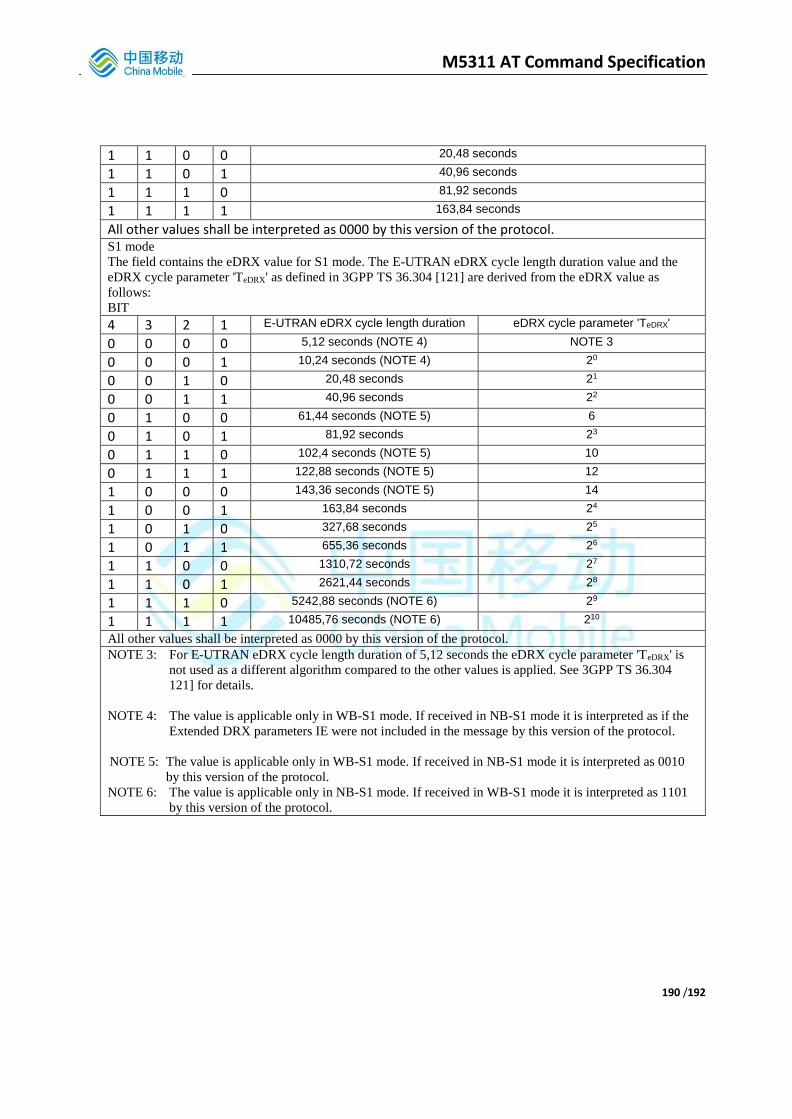
M5311 AT Command Specification
190 /192
1 1 0 0 20,48 seconds
1 1 0 1 40,96 seconds
1 1 1 0 81,92 seconds
1 1 1 1 163,84 seconds
All other values shall be interpreted as 0000 by this version of the protocol. S1 mode
The field contains the eDRX value for S1 mode. The E-UTRAN eDRX cycle length duration value and the
eDRX cycle parameter 'TeDRX' as defined in 3GPP TS 36.304 [121] are derived from the eDRX value as
follows:
BIT 4 3 2 1 E-UTRAN eDRX cycle length duration eDRX cycle parameter 'TeDRX'
0 0 0 0 5,12 seconds (NOTE 4) NOTE 3
0 0 0 1 10,24 seconds (NOTE 4) 20
0 0 1 0 20,48 seconds 21
0 0 1 1 40,96 seconds 22
0 1 0 0 61,44 seconds (NOTE 5) 6
0 1 0 1 81,92 seconds 23
0 1 1 0 102,4 seconds (NOTE 5) 10
0 1 1 1 122,88 seconds (NOTE 5) 12
1 0 0 0 143,36 seconds (NOTE 5) 14
1 0 0 1 163,84 seconds 24
1 0 1 0 327,68 seconds 25
1 0 1 1 655,36 seconds 26
1 1 0 0 1310,72 seconds 27
1 1 0 1 2621,44 seconds 28
1 1 1 0 5242,88 seconds (NOTE 6) 29
1 1 1 1 10485,76 seconds (NOTE 6) 210
All other values shall be interpreted as 0000 by this version of the protocol.
NOTE 3: For E-UTRAN eDRX cycle length duration of 5,12 seconds the eDRX cycle parameter 'TeDRX' is
not used as a different algorithm compared to the other values is applied. See 3GPP TS 36.304
121] for details.
NOTE 4: The value is applicable only in WB-S1 mode. If received in NB-S1 mode it is interpreted as if the
Extended DRX parameters IE were not included in the message by this version of the protocol.
NOTE 5: The value is applicable only in WB-S1 mode. If received in NB-S1 mode it is interpreted as 0010
by this version of the protocol.
NOTE 6: The value is applicable only in NB-S1 mode. If received in WB-S1 mode it is interpreted as 1101
by this version of the protocol.

M5311 AT Command Specification
191 /192
5.2. GPRS Timer (3GPP TS 24.008)
5.2.1 GPRS Timer The purpose of the GPRS timer information element is to specify GPRS specific timer values, e.g. for the READY timer. The GPRS timer is a type 3 information element with 2 octets length. The GPRS timer information element is coded as shown in figure 10.5.146/3GPP TS 24.008 and table 10.5.172/3GPP TS 24.008.
8 7 6 5 4 3 2 1
GPRS Timer IEI octet 1
Unit Timer value octet 2
Figure 10.5.146/3GPP TS 24.008: GPRS Timer information element
Table 10.5.172/3GPP TS 24.008: GPRS Timer information element Timer value (octet 2) Bits 5 to 1 represent the binary coded timer value. Bits 6 to 8 defines the timer value unit for the GPRS timer as follows: Bits 8 7 6
0 0 0 value is incremented in multiples of 2 seconds 0 0 1 value is incremented in multiples of 1 minute 0 1 0 value is incremented in multiples of decihours 1 1 1 value indicates that the timer is deactivated. Other values shall be interpreted as multiples of 1 minute in this version of the protocol.
5.2.2 GPRS Timer 2 The purpose of the GPRS timer 2 information element is to specify GPRS specific timer values, e.g. for the timer T3302 or timer T3319. The GPRS timer 2 is a type 4 information element with 3 octets length. The GPRS timer 2 information element is coded as shown in figure 10.5.147/3GPP TS 24.008 and table 10.5.163/3GPP TS 24.008.
8 7 6 5 4 3 2 1
GPRS Timer 2 IEI octet 1
Length of GPRS Timer 2 contents octet 2
GPRS Timer 2 value octet 3
Figure 10.5.147/3GPP TS 24.008: GPRS Timer 2 information element
Table 10.5.163/3GPP TS 24.008: GPRS Timer 2 information element GPRS Timer 2 value is coded as octet 2 of the GPRS timer information element.

M5311 AT Command Specification
192 /192
5.2.3 GPRS Timer 3 The purpose of the GPRS timer 3 information element is to specify GPRS specific timer values, e.g. for the timer T3396. The GPRS timer 3 is a type 4 information element with 3 octets length. The GPRS timer 3 information element is coded as shown in figure 10.5.147a/3GPP TS 24.008 and table 10.5.163a/3GPP TS 24.008.
8 7 6 5 4 3 2 1
GPRS Timer 3 IEI octet 1
Length of GPRS Timer 3 contents octet 2
Unit Timer value octet 3
Figure 10.5.147a/3GPP TS 24.008: GPRS Timer 3 information element
Table 10.5.163a/3GPP TS 24.008: GPRS Timer 3 information element GPRS Timer 3 value (octet 3) Bits 5 to 1 represent the binary coded timer value. Bits 6 to 8 defines the timer value unit for the GPRS timer as follows: Bits 8 7 6
0 0 0 value is incremented in multiples of 10 minutes 0 0 1 value is incremented in multiples of 1 hour 0 1 0 value is incremented in multiples of 10 hours 0 1 1 value is incremented in multiples of 2 seconds 1 0 0 value is incremented in multiples of 30 seconds 1 0 1 value is incremented in multiples of 1 minute 1 1 0 value is incremented in multiples of 320 hours (NOTE) 1 1 1 value indicates that the timer is deactivated. NOTE: This timer value unit is only applicable to the T3312 extended value IE
and T3412 extended value IE (see 3GPP TS 24.301 [120]). If it is received in an integrity protected message, value shall be interpreted as multiples of 320 hours. Otherwise value shall be interpreted as multiples of 1 hour.