isu at command reference · 2019-07-01 · isu at command reference revision history revision...
TRANSCRIPT
Version 2.0
ISU AT Command Reference
May 20, 2003
Version 2.0 May 20, 2003 i
ISU AT Command Reference Revision History
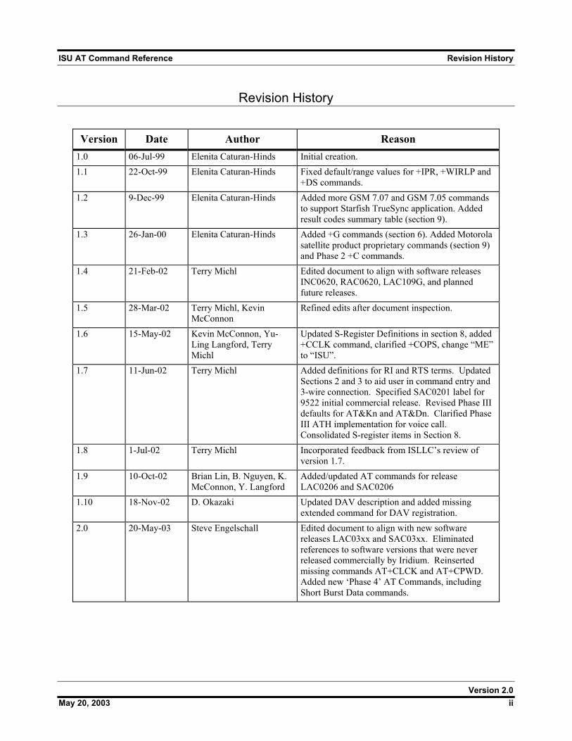
Revision History
Version Date Author Reason
1.0 06-Jul-99 Elenita Caturan-Hinds Initial creation. 1.1 22-Oct-99 Elenita Caturan-Hinds Fixed default/range values for +IPR, +WIRLP and
+DS commands. 1.2 9-Dec-99 Elenita Caturan-Hinds Added more GSM 7.07 and GSM 7.05 commands
to support Starfish TrueSync application. Added result codes summary table (section 9).
1.3 26-Jan-00 Elenita Caturan-Hinds Added +G commands (section 6). Added Motorola satellite product proprietary commands (section 9) and Phase 2 +C commands.
1.4 21-Feb-02 Terry Michl Edited document to align with software releases INC0620, RAC0620, LAC109G, and planned future releases.
1.5 28-Mar-02 Terry Michl, Kevin McConnon
Refined edits after document inspection.
1.6 15-May-02 Kevin McConnon, Yu-Ling Langford, Terry Michl
Updated S-Register Definitions in section 8, added +CCLK command, clarified +COPS, change “ME” to “ISU”.
1.7 11-Jun-02 Terry Michl Added definitions for RI and RTS terms. Updated Sections 2 and 3 to aid user in command entry and 3-wire connection. Specified SAC0201 label for 9522 initial commercial release. Revised Phase III defaults for AT&Kn and AT&Dn. Clarified Phase III ATH implementation for voice call. Consolidated S-register items in Section 8.
1.8 1-Jul-02 Terry Michl Incorporated feedback from ISLLC’s review of version 1.7.
1.9 10-Oct-02 Brian Lin, B. Nguyen, K. McConnon, Y. Langford
Added/updated AT commands for release LAC0206 and SAC0206
1.10 18-Nov-02 D. Okazaki Updated DAV description and added missing extended command for DAV registration.
2.0 20-May-03 Steve Engelschall Edited document to align with new software releases LAC03xx and SAC03xx. Eliminated references to software versions that were never released commercially by Iridium. Reinserted missing commands AT+CLCK and AT+CPWD. Added new ‘Phase 4’ AT Commands, including Short Burst Data commands.
Version 2.0 May 20, 2003 ii
ISU AT Command Reference Table of Contents
Table of Contents
1 Introduction....................................................................................................................1 1.1 Scope.................................................................................................................................................................. 1 1.2 Reference............................................................................................................................................................ 1 1.3 Terms /and Abbreviations .................................................................................................................................. 1
2 Modem Overview ...........................................................................................................4 2.1 DTE-ISU Interchange Circuits ........................................................................................................................... 4 2.2 9-Wire and 3-Wire Operation............................................................................................................................. 4 2.3 Configuration Settings........................................................................................................................................ 4 2.4 Mode of Operation ............................................................................................................................................. 4 2.5 RS232 DAV Service .......................................................................................................................................... 5
3 Command Overview ......................................................................................................6 3.1 Command Types ................................................................................................................................................ 6 3.2 Basic Commands................................................................................................................................................ 6 3.3 Extended Commands.......................................................................................................................................... 6 3.4 Command and Response Characters .................................................................................................................. 7 3.5 Command Entry ................................................................................................................................................. 8 3.6 Command Responses ......................................................................................................................................... 9
4 Phased Implementation by Software Release...........................................................10 5 Phase I AT Commands................................................................................................14
5.1 AT - ATtention Code ....................................................................................................................................... 14 5.2 A/ - Repeat Last Command .............................................................................................................................. 14 5.3 +++ - Escape Sequence .................................................................................................................................... 14 5.4 A - Answer (Initial implementation; revised in Phase III) ............................................................................... 14 5.5 Bn - Communication Standards........................................................................................................................ 14 5.6 Cn - Carrier Control ......................................................................................................................................... 14 5.7 D - Dial (Initial implementation; revised in Phase III)..................................................................................... 15
5.7.1 Direct Dial From Phonebook (Initial implementation; revised in Phase III) ..................................... 15 5.8 En - Echo.......................................................................................................................................................... 16 5.9 Fn - Line Modulation ....................................................................................................................................... 16 5.10 Hn - Hangup (Initial implementation; revised in Phase III) ............................................................................. 16 5.11 In - Identification.............................................................................................................................................. 16 5.12 Ln - Loudspeaker Volume................................................................................................................................ 16 5.13 Mn - Speaker Control ....................................................................................................................................... 16 5.14 Nn - Automode Enable..................................................................................................................................... 17 5.15 On - Online....................................................................................................................................................... 17 5.16 P - Pulse Dial.................................................................................................................................................... 17 5.17 Qn - Quiet Mode............................................................................................................................................... 17 5.18 S0=n - Auto-Answer (Initial implementation; revised in Phase III)................................................................. 17 5.19 T - Tone Dial .................................................................................................................................................... 17
Version 2.0 May 20, 2003 iii
ISU AT Command Reference Table of Contents
5.20 Vn - Verbose Mode .......................................................................................................................................... 18 5.21 Wn - Error Correction Message Control .......................................................................................................... 18 5.22 Xn - Extended Result Codes (Initial implementation; revised in Phase III)..................................................... 18 5.23 Yn - Long Space Disconnect ............................................................................................................................ 18 5.24 Zn - Soft Reset.................................................................................................................................................. 18 5.25 &Cn - DCD Option .......................................................................................................................................... 19 5.26 &Dn - DTR Option (Initial implementation; revised in Phase III)................................................................... 19 5.27 &Fn - Restore Factory Settings ........................................................................................................................ 19 5.28 &Gn - Guard Tone............................................................................................................................................ 19 5.29 &Jn - Jack Control............................................................................................................................................ 20 5.30 &Kn - Flow Control ......................................................................................................................................... 20 5.31 &Ln - Leased Line Operation........................................................................................................................... 20 5.32 &Mn - Asynchronous/Synchronous Mode....................................................................................................... 20 5.33 &Pn - Pulse Dial Make/Break Ratio................................................................................................................. 20 5.34 &Qn - Sync/Async Mode ................................................................................................................................. 20 5.35 &Rn - RTS/CTS Option ................................................................................................................................... 21 5.36 &Sn - DSR Override ........................................................................................................................................ 21 5.37 &V - View Active and Stored Configuration ................................................................................................... 21 5.38 &Wn - Store Active Configuration .................................................................................................................. 21 5.39 &Xn - Select Synchronous Clock..................................................................................................................... 21 5.40 &Yn - Designate Default Reset Profile ............................................................................................................ 21 5.41 \An - MNP Block Size...................................................................................................................................... 21 5.42 \Bn - Transmit Break ........................................................................................................................................ 22 5.43 \Gn - XON/XOFF Flow Control ...................................................................................................................... 22 5.44 \Jn - DTE Auto Rate ......................................................................................................................................... 22 5.45 \Kn - Control Break.......................................................................................................................................... 22 5.46 \Nn - Link Type................................................................................................................................................ 22 5.47 %Cn - Compression Control ............................................................................................................................ 23 5.48 %En - Auto Retrain .......................................................................................................................................... 23 5.49 %R - Display Registers .................................................................................................................................... 23 5.50 *Pn - Power Phone ........................................................................................................................................... 23 5.51 +CBST - Select Bearer Service Type ............................................................................................................... 24 5.52 +CGMI - Manufacturer Identification.............................................................................................................. 24 5.53 +CGMM - Model Identification....................................................................................................................... 24 5.54 +CGMR - Revision .......................................................................................................................................... 24 5.55 +CGSN - Serial Number .................................................................................................................................. 25 5.56 +CMEE - Report Mobile Equipment Error ...................................................................................................... 25 5.57 +CPAS - Phone Activity Status........................................................................................................................ 26 5.58 +CR - Service Reporting Control ..................................................................................................................... 27 5.59 +CRC - Cellular Result Codes (Initial implementation; revised in Phase III).................................................. 27 5.60 +DS - Set Data Compression Function............................................................................................................. 28 5.61 +DR - Data Compression Report Level............................................................................................................ 28 5.62 +IPR - Fixed DTE Rate .................................................................................................................................... 29
Version 2.0 May 20, 2003 iv
ISU AT Command Reference Table of Contents
6 Phase II AT Commands...............................................................................................30 6.1 +CBC - Battery Charge (Initial implementation; revised in Phase III) ............................................................ 30 6.2 +CEER - Extended Error Report...................................................................................................................... 30 6.3 +CHUP - Hangup call ...................................................................................................................................... 30 6.4 +CLCK - Facility Lock .................................................................................................................................... 31 6.5 +CMGD - Delete SMS Message ...................................................................................................................... 31 6.6 +CMGF - SMS Message Format...................................................................................................................... 33 6.7 +CMGL - List SMS Messages ......................................................................................................................... 34 6.8 +CMGR - Read SMS Message ........................................................................................................................ 34 6.9 +CMGS - Send SMS Message ......................................................................................................................... 35 6.10 +CMGW - Write SMS Message To Memory................................................................................................... 35 6.11 +CMOD - Call Mode ....................................................................................................................................... 35 6.12 +CNMI - New SMS Message Indications to DTE ........................................................................................... 36 6.13 +COPS - Operator Select.................................................................................................................................. 37 6.14 +CPBF - Find phonebook entries ..................................................................................................................... 38 6.15 +CPBR - Read phonebook entries.................................................................................................................... 38 6.16 +CPBS - Select phonebook storage.................................................................................................................. 39 6.17 +CPBW - Write phonebook entry .................................................................................................................... 39 6.18 +CPIN - Enter PIN ........................................................................................................................................... 40 6.19 +CPMS - Select Preferred SMS Message Storage ........................................................................................... 41 6.20 +CPWD - Change Password ............................................................................................................................ 41 6.21 +CREG - Network Registration ....................................................................................................................... 42 6.22 +CSCA - SMS Service Center Address ........................................................................................................... 43 6.23 +CSCB - Select Cell Broadcast Message Types .............................................................................................. 43 6.24 +CSCS - Select TE Character Set..................................................................................................................... 43 6.25 +CSMS - Select SMS Message Service ........................................................................................................... 44 6.26 +CSTA - Select Type of Address ..................................................................................................................... 44 6.27 +GMI - Manufacturer Identification................................................................................................................. 44 6.28 +GMM - Model Identification.......................................................................................................................... 45 6.29 +GMR - Revision ............................................................................................................................................. 45 6.30 +GSN - Serial Number ..................................................................................................................................... 45 6.31 +GCAP - General Capabilities ......................................................................................................................... 45
7 Phase III AT Commands..............................................................................................46 7.1 A - Answer (Revised)....................................................................................................................................... 46 7.2 D - Dial (Revised) ............................................................................................................................................ 46
7.2.1 Direct Dial From Phonebook (Revised)............................................................................................. 47 7.3 Hn - Hangup (Revised)..................................................................................................................................... 47 7.4 S0=n - Auto-Answer (Revised) ........................................................................................................................ 47 7.5 Xn - Extended Result Codes (Revised) ............................................................................................................ 48 7.6 &Dn - DTR Option (Revised) .......................................................................................................................... 48 7.7 +CBC - Battery Charge (Revised).................................................................................................................... 49 7.8 +CSQ - Signal Quality ..................................................................................................................................... 50
Version 2.0 May 20, 2003 v
7.9 +CLVL - Loudspeaker Volume Level Control ................................................................................................ 51
ISU AT Command Reference Table of Contents
7.10 +CMUT - Mute Control ................................................................................................................................... 51 7.11 +CRC - Cellular Result Codes (Revised) ......................................................................................................... 52 7.12 +CVHU - Voice Hangup Control..................................................................................................................... 52 7.13 +CCLK - Real-Time Clock .............................................................................................................................. 53 7.14 -MSVTS - DTMF Generation in Voice Call .................................................................................................... 53 7.15 -MSVTR - DTMF Received in Voice Call....................................................................................................... 54 7.16 -MSVLS - Local DTMF Feedback Selection................................................................................................... 54 7.17 -MSSTM - Request System Time .................................................................................................................... 55
8 Phase IV AT Commands .............................................................................................56 8.1 –MSGEO - Request Geolocation ..................................................................................................................... 56 8.2 +CCFC - Call Forward service......................................................................................................................... 56 8.3 +CLCC - Request Current Call Status.............................................................................................................. 57 8.4 +CNUM - Read MSISDN Numbers................................................................................................................. 57 8.5 +WIRLP - Iridium Radio Link Protocol .......................................................................................................... 58 8.6 +WFRNG - Force IRLP Renegotiation............................................................................................................ 59 8.7 +WTM - IRLP Test Mode................................................................................................................................ 59 8.8 +WDLDM - IRLP Dynamic Link Delay Measurement ................................................................................... 60 8.9 +WDAV - Register or Deregister an RS232 DAV Data Peripheral................................................................. 60 8.10 +SBDWB - Short Burst Data: Write Binary Data to the ISU........................................................................... 61 8.11 +SBDRB - Short Burst Data: Read Binary Data from ISU.............................................................................. 62 8.12 +SBDWT - Short Burst Data: Write a Text Message to the ISU ..................................................................... 62 8.13 +SBDRT - Short Burst Data: Read a Text Message from the ISU................................................................... 63 8.14 +SBDI - Short Burst Data: Initiate an SBD Session......................................................................................... 63 8.15 +SBDD - Short Burst Data: Clear SBD Message Buffer(s) ............................................................................. 65 8.16 +SBDC - Short Burst Data: Clear SBD MOMSN............................................................................................ 65 8.17 +SBDS - Short Burst Data: Status.................................................................................................................... 66 8.18 +SBDTC - Short Burst Data: Transfer MO Buffer to MT Buffer .................................................................... 66
9 S-Register Definitions .................................................................................................67 9.1 S-Register Commands...................................................................................................................................... 67
9.1.1 Sr - Direct S-Register Reference........................................................................................................ 67 9.1.2 Sr? - Direct S-Register Read .............................................................................................................. 67 9.1.3 Sr=n - Direct S-Register Write........................................................................................................... 67 9.1.4 ? - Referenced S-Register Read ......................................................................................................... 67 9.1.5 =n - Referenced S-Register Write ...................................................................................................... 67
9.2 Standard S-Registers ........................................................................................................................................ 68 9.3 Iridium Specific S-Register Extensions............................................................................................................ 70
10 Summary of Result Codes ..........................................................................................72 11 Informative Examples..................................................................................................74
11.1 Unit Identification ............................................................................................................................................ 74 11.2 Originating a Data Call..................................................................................................................................... 74 11.3 Answering a Data Call...................................................................................................................................... 74 11.4 Disconnecting a Data Call ................................................................................................................................ 75
Version 2.0 May 20, 2003 vi
ISU AT Command Reference Table of Contents
11.5 Originating an RS232 DAV Data Call ............................................................................................................. 75 11.6 Answering an RS232 DAV Data Call .............................................................................................................. 75 11.7 Disconnecting an RS232 DAV Data Call......................................................................................................... 75 11.8 Originating and Disconnecting a Voice Call .................................................................................................... 76 11.9 Coordination of +CLCC and +CPAS responses............................................................................................... 76 11.10 Usage examples of +CCFC command.............................................................................................................. 77
Version 2.0 May 20, 2003 vii
ISU AT Command Reference Introduction
1 Introduction
1.1 Scope This document is intended as a reference guide to the usage of the AT command set for the IridiumTM/SM sub-scriber unit. This document only applies to the Motorola satellite series. The intended audience for this document are the field test engineers, product and intelligent peripheral developers.
1.2 Reference [1] ITU-T Recommendation V.25ter, 08/95. [2] ETS 300 642: Digital Cellular Telecommunications System (Phase 2); AT Command Set for GSM
Mobile Equipment (GSM 07.07). [3] ETS 300 585: Digital Cellular Telecommunications System (Phase 2); Use of DTE-DCE Interface
SMS and CBS (GSM 07.05) [4] ITU-T Recommendation V.24, 03/93.
1.3 Terms /and Abbreviations Asynchronous
A serial data transmission method that uses Start and Stop bits to synchronize reception. AT Commands
A group of commands that can be sent by a terminal or host computer to control the ISU in Command mode.
Baud One signalling element per second. This is a measure of the signalling rate on the telephone line. It should not be confused with Bits Per Second (bps) which can differ from the Baud rate.
BCD Binary Coded Decimal
Bit Mapped Registers Bit mapping is a technique that allows a single S-Register to hold up to 8 binary variables e.g.: Reg Type Val Default Function S14 Bit Mapped 170 Register S14 is a bit-mapped register and provides the following functions: Bit 0 Reserved Bit 1 Echo commands to DTE Bit 2 Responses Bit 3 Word or number responses Bit 4 Reserved Bit 5 Dialing method Bit 6 Reserved Bit 7 Answer/Originate operation
Version 2.0 May 20, 2003 1
ISU AT Command Reference Introduction
CI Cell Identifier
CTS (V.24 Signal) Clear To Send. This signal is normally used in controlling the flow of data to the ISU. (See RTS)
DCD (V.24 Signal) Data Carrier Detect. This is a signal from the ISU that indicates that it is connected to the far-end modem for data transfer.
DCE Data Communications Equipment, i.e., a data adaptor or modem. In this product, DCE refers to the ISU.
DSR (V.24 Signal) Data Set Ready. This signal, from the ISU, indicates the readiness of the phone to receive data.
DTE Data Terminal Equipment, such as a dumb terminal, or a PC running communications software.
DTR (V.24 Signal) Data Terminal Ready. A signal from the DTE to the ISU. Can be used to terminate calls.
ESS ETC SBD Subsystem ETC Earth Terminal Controller ETSI
European Telecommunications Standards Institute. FA Field Application GSM
Global System for Mobile communications. IRLP
Iridium Radio Link Protocol ISU
Individual Subscriber Unit LAC
Location Area Code Modem
MOdulator/DEModulator. A device used to convert digital signals to analog signals for transmission and reception of telephone lines.
MO Mobile Originated (for Short Burst Data) MOMSN Mobile Originated Message Sequence Number (for Short Burst Data)
Version 2.0 May 20, 2003 2
ISU AT Command Reference Introduction
MT Mobile Terminated (for Short Burst Data) MTMSN Mobile Terminated Message Sequence Number (for Short Burst Data) RI
(V.24 Signal) Ring Indicate. This is a signal from the ISU which indicates that an incoming call is ringing.
RP Relay Protocol (used in SMS).
RTS (V.24 Signal) Request To Send. This signal is normally used in controlling the flow of data from the ISU.
SBD Short Burst Data SMS
SMS Short Message Service. SMSSC
Short Message Service - Service Centre (used in SMS). TP
Transfer Protocol (used in SMS). XON/XOFF
A standard method of controlling the flow of data to and from a ISU to prevent overflow/overrun conditions.
Version 2.0 May 20, 2003 3
ISU AT Command Reference Modem Overview
2 Modem Overview
2.1 DTE-ISU Interchange Circuits The communication between the ISU (Iridium Subscriber Unit) and the DTE (Data Terminal Equipment) follows the ITU-T V.24 (RS-232) recommendation. Please see reference [4] for details.
2.2 9-Wire and 3-Wire Operation The ISU supports a full 9-wire interface to the DTE, incorporating hardware handshaking and flow control. A 3-wire DTE interface, where only transmit, receive, and ground signals are used, is supported in those ISUs where the AT&D0 command has been revised to ignore the DTR (Data Terminal Ready) signal. When operating with a 3-wire connection, the following limitations apply:
AT&Dn must be set to AT&D0 to ignore the DTR input from the DTE, as it will not be present as an input from the DTE
•
•
•
•
•
AT&Kn must be set to AT&K0 for no flow control or AT&K4 for XON/XOFF software flow control, as RTS (Request To Send) and CTS (Clear To Send) hardware flow control signals will not be present AT&Cn setting will have no affect, as DCD (Data Carrier Detect) output to the DTE will not be present AT&Sn setting will have no affect, as DSR (Data Set Ready) output to the DTE will not be present RI (Ring Indicate) output to the DTE will not be present
2.3 Configuration Settings The ISU allows the DTE to configure the communication parameters. The three configuration types are active, factory default, and stored. The active configuration is the set of parameters currently in use. They can be changed by the DTE individually via specific AT commands. The factory default configuration is stored in permanent memory. This configuration can be recalled at any time by through use of the AT&Fn command. Two groups of settings, or “profiles”, can be stored as user-defined configuration. The DTE first creates desired active configurations and then writes them to memory using the AT&Wn command. These profiles can be designated to be loaded as the active configuration upon ISU power-up through use of the AT&Yn command. Similarly, the ISU can be reset without loss of power to these profiles through use of the ATZn command. Most of the configuration settings are reflected in “S-register” locations. S-register is the term used by Hayes-compatible modems for a specific physical location in memory.
2.4 Mode of Operation The ISU is always in one of two modes: command mode or data mode. When the ISU is in command mode, AT commands can be entered to control the phone. Note that command mode can be accessed while on-hook (i.e. not in a call) or in-call. When in data mode, the ISU is connected to a remote system and any characters sent to it will be transmitted to the remote system. Note that data mode can be only accessed while in-call. While in-call, the Escape Sequence (+++) is used to enter the command mode. The Online command (ATOn) is used to return to the data mode. These mode transitions are made without terminating the call.
Version 2.0 May 20, 2003 4
ISU AT Command Reference Modem Overview
2.5 RS232 DAV Service
RS232 DAV (Data After Voice) service provides data transfer between RS232 peripherals interfaced to peer Iridium Subscriber Units (ISU). While the RS232 peripheral’s data application sees little difference in an RS232 DAV data transfer versus a standard data call data transfer, the call topology is quite different. An RS232 DAV data transfer uses a voice call topology, not a data call topology. The peer ISUs are connected in a voice call, but the voice packet payload is filled with data sourced from the RS232 peripherals, instead of digitized voice. As such, an RS232 DAV call is not routed through a gateway modem interworking function, as is the case with a standard data call. From the network point of view, an RS232 DAV call is just a voice call, regardless of whether the MSISDN or MSISDN-C number is called. Note that any type of ISU to ISU call, voice (including RS232 DAV), or data, can use either phone number to place the call, relying on the network to determine the call type during call setup negotiation with the ISU. Dialing rules can be found in the Iridium Mobile- Terminated Data User’s Guide. A common aspect of an RS232 DAV call and a standard data call is that both calls set the ISUs to full output power in order to provide a more robust data link. Also, an RS232 DAV call, like a standard data call, defaults to an acknowledged data transfer mode (a.k.a. reliable, nontransparent mode). Again like a standard data call, the data transfer mode can be set to transparent (a.k.a. unreliable, unacknowledged mode) on a call-by-call basis. This is done by a pre-call issuance of the AT&Q0 command by both peer ISU RS232 peripherals. Note that since a standard data call is routed through a gateway modem interworking function, the call-originator and call-terminator ISUs establish their data transfer mode with their gateway modem interworking function peers. With an RS232 DAV call, data transfer mode is established directly between the peer ISUs. Using the RS232 DAV service is very similar to a standard data call. The RS232 DAV service supports the same set of AT commands used in a standard data call, and utilizes one additional command to set the RS232 DAV mode. Issuing AT+WDAV=1 registers the RS232 peripheral as an RS232 DAV peripheral. Once issued, a subsequent data call dialing command is interpreted as a DAV dialing call command. “Data Call in Progress” is flashed on the call-originator ISU, and a voice call is placed. The call-terminator ISU, also having its RS232 peripheral registered as an RS232 DAV peripheral with the AT+WDAV=1 command, answers the voice call. At this point, the “Data Call in Progress” display on the call-originator ISU is shown steady. The call-originator ISU then sends a special DTMF sequence to the call-terminator ISU, requesting it to switch to DAV mode. The call-terminator ISU responds by sending a special DTMF sequence to the call-originator ISU to accept the DAV mode request. DAV mode is then established, and the call-terminator ISU shows the same “Data Call in Progress” display as the call-originator ISU. The RS232 peripherals can now proceed as if in a standard data call. Subsequent data call dialing commands will continue to be interpreted as RS232 DAV dialing call commands, until the RS232 peripheral is deregistered as an RS232 DAV peripheral. Note that if the RS232 DAV peripheral is deregistered during an RS232 DAV call, the call will be dropped. RS232 DAV peripheral deregistration is accomplished by one of three means: 1. Issuance of the AT+WDAV=0 command 2. Power cycling of the ISU 3. Physical disconnection of the RS232 DAV peripheral, based on the loss of the DTR signal (Note that reaction to DTR signal loss is disabled with the AT&D0 command.)
Version 2.0 May 20, 2003 5
ISU AT Command Reference Command Overview
3 Command Overview
3.1 Command Types The ISU employs two principle types of AT commands: basic and extended. The two types have differing syntax used to query and adjust their settings. They also have unique reference standards. A specific basic AT command is used to reference S-registers and query and adjust their settings. Its syntax is similar to that of extended AT commands.
3.2 Basic Commands Basic commands are industry standard and originally developed for Hayes-compatible PSTN modems. In many cases, basic commands consist of a single ASCII alpha character. In other cases, a special character precedes the alpha character. Prefix characters used in ISU basic commands include &, \, %, and *. Most alpha characters in basic commands are followed by a numeric parameter, n. To adjust its setting, a basic command is entered with the appropriate numeric value of n. Note that if the numeric parameter n is omitted from the basic command entry, a value of zero is assumed for n. For example, ATXn is set to a value of 4 by entering ATX4, whereas it is set to value of 0 by entering either ATX0 or ATX. To query a basic command setting, the AT&V command is entered to view the active configuration of a group of basic commands. Some basic commands listed in this document are marked with “No action, compatibility only”. In these cases, the basic command is accepted in the same fashion as is with other modems, but has no effect on the operation of the ISU, since it has no meaning in the IridiumTM/SM environment.
3.3 Extended Commands Extended commands perform actions or set parameters that extend the capability of the ISU beyond that which is allowed by basic commands. In some cases, they were designed for non-PSTN networks, such as the GSM network. Most extended commands include a prefix of + followed by a single alpha character. Prefixes used in ISU extended commands include +C, +D, +G, and +I. Extended commands designed specifically for the Motorola Satellite Series product line include a -MS prefix. Most extended commands include three alpha characters after the prefix, but some commands include just one or two alpha characters after the prefix. Some extended commands have a single execution mode. No further syntax is added after the prefix and body of the command. For example, AT+GSN is entered as shown to query the ISU for its assigned serial number (i.e. IMEI). Some extended commands incorporate a test mode to query their range of valid responses. For example, AT+CBC is entered as shown in execution mode to query the ISU for its battery connection and charge status. The command is entered as AT+CBC=? in test mode to query its range of valid responses. Some extended commands incorporate set, read, and test modes. For example, AT-MSVTR is entered as AT-MSVTR=n in set mode to enable/disable receipt of DTMF messages. It is entered as AT-MSVTR? in read mode to query its current setting and is entered as AT-MSVTR=? in test mode to query its range of valid settings. Extended commands are grouped as shown on the following page.
Version 2.0 May 20, 2003 6
ISU AT Command Reference Command Overview
Extended Cellular Commands +C prefix •
•
•
•
•
•
•
•
•
Used for GSM cellular phone-like functions Standards: ETSI specifications GSM 07.07 (reference [2]) and GSM 07.05 (reference [3])
Extended Data Compression Commands
+D prefix Used for data compression Standard: V.25ter (reference [1])
Extended Generic Commands
+G prefix Used for generic DCE issues such as identities and capabilities Standard: V.25ter (reference [1])
Extended Interface Control Commands • +I prefix • Used to control the DTE interface • Standard: V.25ter (reference [1]) Motorola Satellite Product Proprietary Commands • -MS prefix • Proprietary to the Motorola Satellite Series product line
3.4 Command and Response Characters The execution of a command string follows a left-to-right execution of each command followed by the reporting of a result code for the entire string. The ASCII character set (CCITT T.50 International Alphabet 5, American Standard Code for Information Interchange) is used for the issuance of commands and responses. Only the low-order 7 bits of each character are used for commands or parameters; the high-order bit is ignored. Upper case characters are equivalent to lower case characters.
Version 2.0 May 20, 2003 7
ISU AT Command Reference Command Overview
3.5 Command Entry An AT command is a string of characters sent by the DTE to the ISU while the ISU is in command mode. A command string has a prefix, a body, and a terminator. The prefix consists of the ASCII characters AT or at. The body is a string of commands restricted to printable ASCII characters. The default terminator is the <CR> character. AT command entry syntax is critical, and the following rules apply: • All commands (apart from A/ and +++) begin with a prefix of AT or at. • The commands in a command string (apart from A/ and +++) are executed only after the return or
enter key is pressed. • Use of upper or lower case letters is allowed, but not a combination of both. • The maximum number of characters in a command string is 128. • If the numeric parameter n is omitted from the basic command entry, a value of zero is assumed for n. • If an optional parameter is omitted from an extended command, the current value is implied. Optional
parameters are enclosed by square brackets ([...]) in this document. • Multiple commands can be concatenated onto a single command line by separating the additional non-
prefixed commands with a space or a semicolon or with no separator whatsoever. • Spaces entered into a command string for clarity between the AT prefix and the body of the command
are ignored. Likewise, spaces entered for clarity within the command body between alpha characters and decimal parameters are ignored.
• The backspace or delete keys can typically be used to edit commands. • Characters that precede the AT prefix are ignored. • Ctrl-x can be used to abort a command line input. Consider the following six commands to be entered in a single command line: ATX0 (set basic command ATXn to n=0) AT&V (execute basic command AT&V) AT+GSN (execute extended command AT+GSN) AT+CBC=? (query the valid range of responses of extended command AT+CBC) AT+CPBR=1,12 (execute extended command AT+CPBR with parameters 1 and 12) AT-MSVLS? (query the current setting of extended command AT-MSVLS) The following are valid single command line entries of above six commands: at x 0 &v +gsn +cbc=? +cpbr=1,12 -msvls? (all lower case) AT X 0 &V +GSN +CBC=? +CPBR=1,12 -MSVLS? (all upper case) ATX 0 &V +GSN +CBC=? +CPBR=1,12 -MSVLS? (space omitted between AT and X) ATX0 &V +GSN +CBC=? +CPBR=1,12 -MSVLS? (space omitted between ATX and 0) ATX &V +GSN +CBC=? +CPBR=1,12 -MSVLS? (0 omitted from ATX0) ATX;&V;+GSN;+CBC=?;+CPBR=1,12;-MSVLS? (semicolon separators) ATX&V+GSN+CBC=?+CPBR=1,12-MSVLS? (no separators)
Version 2.0 May 20, 2003 8
ISU AT Command Reference Command Overview
3.6 Command Responses A result code is sent to the DTE in response to the execution of a command. It may also occur unsolicited from other conditions such as an incoming call (e.g., RING). Responses returned as a result of a query are called information responses. Result codes can be represented by text if the ISU is in verbose mode or with numbers if in numeric mode. The command ATVn informs the ISU whether to respond in verbose or numeric mode. Further note that responses can be suppressed with by setting the command ATQn to ATQ1. Table 3-1 below shows the difference in format between these modes.
Table 3-1: Result Code Response Format
Numeric Mode ATQ0 ATV0
Verbose Mode ATQ0 ATV1
Result codes <NUMERIC_CODE><CR> <CR><LF><VERBOSE_CODE><CR><LF>
Information Responses <TEXT><CR><LF> <CR><LF><TEXT><CR><LF>
Command entries with invalid syntax typically respond with ERROR. Command entries of valid syntax with an out-of-range parameter can respond in one of three following manners:
Disallow out-of-range entry and respond with ERROR •
•
•
Disallow out-of-range entry and respond with OK Disallow out-of-range entry, accept the closest in-range value, and respond with OK
Version 2.0 May 20, 2003 9
ISU AT Command Reference Phased Implementation by Software Release
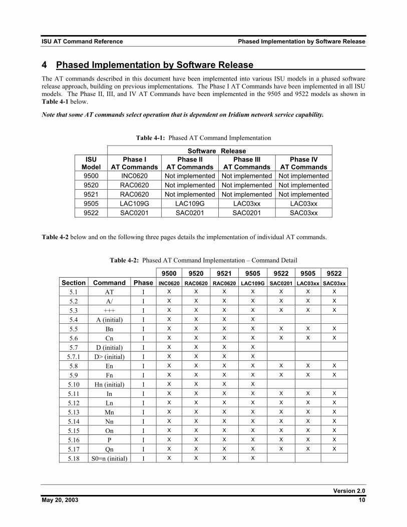
4 Phased Implementation by Software Release The AT commands described in this document have been implemented into various ISU models in a phased software release approach, building on previous implementations. The Phase I AT Commands have been implemented in all ISU models. The Phase II, III, and IV AT Commands have been implemented in the 9505 and 9522 models as shown in Table 4-1 below.
Note that some AT commands select operation that is dependent on Iridium network service capability.
Table 4-1: Phased AT Command Implementation
Software Release ISU
Model Phase I
AT Commands Phase II
AT Commands Phase III
AT Commands Phase IV
AT Commands 9500 INC0620 Not implemented Not implemented Not implemented9520 RAC0620 Not implemented Not implemented Not implemented9521 RAC0620 Not implemented Not implemented Not implemented9505 LAC109G LAC109G LAC03xx LAC03xx 9522 SAC0201 SAC0201 SAC0201 SAC03xx
Table 4-2 below and on the following three pages details the implementation of individual AT commands.
Table 4-2: Phased AT Command Implementation – Command Detail
9500 9520 9521 9505 9522 9505 9522 Section Command Phase INC0620 RAC0620 RAC0620 LAC109G SAC0201 LAC03xx SAC03xx
5.1 AT I X X X X X X X
5.2 A/ I X X X X X X X
5.3 +++ I X X X X X X X
5.4 A (initial) I X X X X
5.5 Bn I X X X X X X X
5.6 Cn I X X X X X X X
5.7 D (initial) I X X X X
5.7.1 D> (initial) I X X X X
5.8 En I X X X X X X X
5.9 Fn I X X X X X X X
5.10 Hn (initial) I X X X X
5.11 In I X X X X X X X
5.12 Ln I X X X X X X X
5.13 Mn I X X X X X X X
5.14 Nn I X X X X X X X
5.15 On I X X X X X X X
5.16 P I X X X X X X X
5.17 Qn I X X X X X X X
5.18 S0=n (initial) I X X X X
Version 2.0 May 20, 2003 10
ISU AT Command Reference Phased Implementation by Software Release
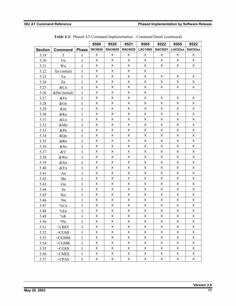
Table 4-2: Phased AT Command Implementation – Command Detail (continued)
9500 9520 9521 9505 9522 9505 9522 Section Command Phase INC0620 RAC0620 RAC0620 LAC109G SAC0201 LAC03xx SAC03xx
5.19 T I X X X X X X X
5.20 Vn I X X X X X X X
5.21 Wn I X X X X X X X
5.22 Xn (initial) I X X X X
5.23 Yn I X X X X X X X
5.24 Zn I X X X X X X X
5.25 &Cn I X X X X X X X
5.26 &Dn (initial) I X X X X
5.27 &Fn I X X X X X X X
5.28 &Gn I X X X X X X X
5.29 &Jn I X X X X X X X
5.30 &Kn I X X X X X X X
5.31 &Ln I X X X X X X X
5.32 &Mn I X X X X X X X
5.33 &Pn I X X X X X X X
5.34 &Qn I X X X X X X X
5.35 &Rn I X X X X X X X
5.36 &Sn I X X X X X X X
5.37 &V I X X X X X X X
5.38 &Wn I X X X X X X X
5.39 &Xn I X X X X X X X
5.40 &Yn I X X X X X X X
5.41 \An I X X X X X X X
5.42 \Bn I X X X X X X X
5.43 \Gn I X X X X X X X
5.44 \Jn I X X X X X X X
5.45 \Kn I X X X X X X X
5.46 \Nn I X X X X X X X
5.47 %Cn I X X X X X X X
5.48 %En I X X X X X X X
5.49 %R I X X X X X X X
5.50 *Pn I X X X X X X X
5.51 +CBST I X X X X X X X
5.52 +CGMI I X X X X X X X
5.53 +CGMM I X X X X X X X
5.54 +CGMR I X X X X X X X
5.55 +CGSN I X X X X X X X
5.56 +CMEE I X X X X X X X
5.57 +CPAS I X X X X X X X
Version 2.0 May 20, 2003 11
ISU AT Command Reference Phased Implementation by Software Release
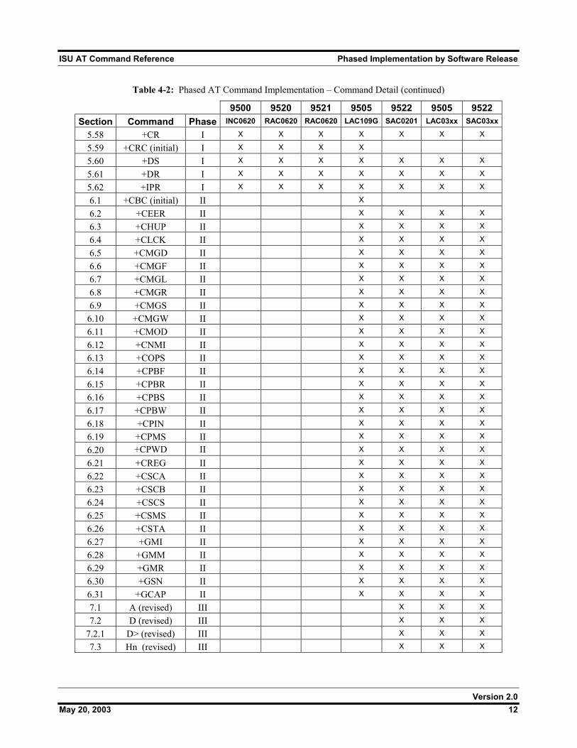
Table 4-2: Phased AT Command Implementation – Command Detail (continued)
9500 9520 9521 9505 9522 9505 9522 Section Command Phase INC0620 RAC0620 RAC0620 LAC109G SAC0201 LAC03xx SAC03xx
5.58 +CR I X X X X X X X
5.59 +CRC (initial) I X X X X
5.60 +DS I X X X X X X X
5.61 +DR I X X X X X X X
5.62 +IPR I X X X X X X X
6.1 +CBC (initial) II X
6.2 +CEER II X X X X
6.3 +CHUP II X X X X
6.4 +CLCK II X X X X
6.5 +CMGD II X X X X
6.6 +CMGF II X X X X
6.7 +CMGL II X X X X
6.8 +CMGR II X X X X
6.9 +CMGS II X X X X
6.10 +CMGW II X X X X
6.11 +CMOD II X X X X
6.12 +CNMI II X X X X
6.13 +COPS II X X X X
6.14 +CPBF II X X X X
6.15 +CPBR II X X X X
6.16 +CPBS II X X X X
6.17 +CPBW II X X X X
6.18 +CPIN II X X X X
6.19 +CPMS II X X X X
6.20 +CPWD II X X X X
6.21 +CREG II X X X X
6.22 +CSCA II X X X X
6.23 +CSCB II X X X X
6.24 +CSCS II X X X X
6.25 +CSMS II X X X X
6.26 +CSTA II X X X X
6.27 +GMI II X X X X
6.28 +GMM II X X X X
6.29 +GMR II X X X X
6.30 +GSN II X X X X
6.31 +GCAP II X X X X
7.1 A (revised) III X X X
7.2 D (revised) III X X X
7.2.1 D> (revised) III X X X
7.3 Hn (revised) III X X X
Version 2.0 May 20, 2003 12
ISU AT Command Reference Phased Implementation by Software Release
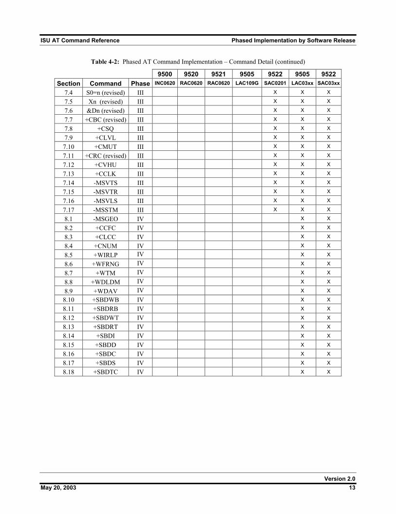
Table 4-2: Phased AT Command Implementation – Command Detail (continued)
9500 9520 9521 9505 9522 9505 9522 Section Command Phase INC0620 RAC0620 RAC0620 LAC109G SAC0201 LAC03xx SAC03xx
7.4 S0=n (revised) III X X X
7.5 Xn (revised) III X X X
7.6 &Dn (revised) III X X X
7.7 +CBC (revised) III X X X
7.8 +CSQ III X X X
7.9 +CLVL III X X X
7.10 +CMUT III X X X
7.11 +CRC (revised) III X X X
7.12 +CVHU III X X X
7.13 +CCLK III X X X
7.14 -MSVTS III X X X
7.15 -MSVTR III X X X
7.16 -MSVLS III X X X
7.17 -MSSTM III X X X
8.1 -MSGEO IV X X
8.2 +CCFC IV X X
8.3 +CLCC IV X X
8.4 +CNUM IV X X
8.5 +WIRLP IV X X
8.6 +WFRNG IV X X
8.7 +WTM IV X X
8.8 +WDLDM IV X X
8.9 +WDAV IV X X
8.10 +SBDWB IV X X
8.11 +SBDRB IV X X
8.12 +SBDWT IV X X
8.13 +SBDRT IV X X
8.14 +SBDI IV X X
8.15 +SBDD IV X X
8.16 +SBDC IV X X
8.17 +SBDS IV X X
8.18 +SBDTC IV X X
Version 2.0 May 20, 2003 13
ISU AT Command Reference Phase I AT Commands
5 Phase I AT Commands
5.1 AT - ATtention Code This is the prefix for all commands except A/ and +++. When entered on its own, the ISU will respond OK.
5.2 A/ - Repeat Last Command Repeat the last command issued to the ISU unless the power was interrupted or the unit is reset. A/ is not followed by <CR>.
5.3 +++ - Escape Sequence The escape sequence is used to transfer from in-call data mode to in-call command mode without disconnecting from the remote modem. After a pause, the ISU will respond with OK. Register S2 can be used to alter the escape character from +, the factory default, to any hexadecimal value in the range 0 to 255.
5.4 A - Answer (Initial implementation; revised in Phase III) Answer immediately. This causes the ISU to answer the incoming data call.
5.5 Bn - Communication Standards Select the communications standard to be used for data calls. No action, compatibility only. Any value for n accepted.
5.6 Cn - Carrier Control Control carrier detection. No action, compatibility only. Only n=1 accepted.
Version 2.0 May 20, 2003 14
ISU AT Command Reference Phase I AT Commands
5.7 D - Dial (Initial implementation; revised in Phase III) Dial a data call number. The dial command causes the ISU to enter originate mode and act as an auto dialer for connection to other modems. The usual format is ATDnx..x where n is a Dial Modifier and x is a number. The following are valid numbers: 0123456789*#ABC. Dial modifiers are used to alter the manner in which the ISU dials. L Redial last number. P Use pulse dialing. No action, compatibility only. T Use tone dialing. No action, compatibility only. + International dialing prefix. Allows the international access code to be omitted from dial
string. > Direct dial from phonebook locations. See subsection below for further details. Direct dial from phonebook not implemented in models 9500 with INC0620, 9520 with
RAC0620, or 9521 with RAC0620 . Any character received from the DTE during the call establishment phase will cause the call attempted to be terminated.
5.7.1 Direct Dial From Phonebook (Initial implementation; revised in Phase III) The ISU and SIM contain phonebooks which have a phone number and an alphanumeric field for each phonebook entry location. The use of V.25ter dialing command ensures that direct dialing from phone memory and SIM phonebook is possible through ordinary communications software which just gives the phone number field to be filled and then use the D command to originate the call. Available memories may be queried with Select Phonebook Storage test command +CPBS=?, and location range for example with Read Phonebook Entries test command +CPBR=?. Execute commands: D><str> Originate call to phone number which corresponding alphanumeric field is <str> (if possible, all available memories should be searched for the correct entry). <str> is of string type value and should enclosed by ““ (e.g., “John”). D> mem<n> Originate call to phone number in memory mem entry location <n> (available memories may be queried with Select Phonebook Storage test command +CPBS=?). mem can be one of the following: FD SIM fixed dialing phonebook LD Last ten calls dialed phonebook ME Phone memory MT Combined phone and SIM phonebook locations SM SIM phonebook D><n> Originate call to phone number in entry location <n> (the command Select Phonebook Memory Storage +CPBS setting determines which phonebook storage is used).
Version 2.0 May 20, 2003 15
ISU AT Command Reference Phase I AT Commands
5.8 En - Echo Echo command characters. 0 Characters are not echoed to the DTE. 1 Characters are echoed to the DTE (default).
5.9 Fn - Line Modulation Select line modulation standard. No action, compatibility only. Allowed values for n are 0, 1, 3, 4, 5, 6, 7, 8, 9 and 10.
5.10 Hn - Hangup (Initial implementation; revised in Phase III) Control the hook switch. This command is used to clear a data call connection. 0 Place the ISU on hook.
5.11 In - Identification Requests the ISU to display information about itself. 0 “2400” (traffic channel rate for IRIDIUM data/fax) 1 “0000” (ROM checksum which is not supported so zero is output) 2 “OK” (result of ROM checksum verification which is not supported so OK is always out-
put) 3 “XXXXXXXX” (Software revision level) 4 “Motorola IRIDIUM” (Product description) 5 “XXXX” (country code) 6 “XXXXXXXX” (Hardware specification)
5.12 Ln - Loudspeaker Volume Set the loudspeaker volume according to the parameter supplied. No action, compatibility only. Allowed values for n are 0, 1, 2 and 3.
5.13 Mn - Speaker Control Select when the speaker will be on or off. Note that serially connected products have no speaker. No action, compatibility only. Allowed values for n are 0, 1, 2 and 3.
Version 2.0 May 20, 2003 16
ISU AT Command Reference Phase I AT Commands
5.14 Nn - Automode Enable Enable or disable automode detection. No action, compatibility only. Any value for n is accepted.
5.15 On - Online Enter in-call data mode. This is used to return to in-call data mode from in-call command mode using an existing connection. An error is reported if on-hook. 0 Switch from in-call command mode to in-call data mode. Any value for n accepted.
5.16 P - Pulse Dial Set pulse dial. No action, compatibility only.
5.17 Qn - Quiet Mode Control ISU responses. 0 ISU responses are sent to the DTE (default). 1 ISU responses are NOT sent to the DTE.
5.18 S0=n - Auto-Answer (Initial implementation; revised in Phase III) Auto-answer. This causes the ISU to auto-answer the incoming data call. 0 Disable auto-answer. n>0 Enable auto-answer.
5.19 T - Tone Dial Set tone dial. No action, compatibility only.
Version 2.0 May 20, 2003 17
ISU AT Command Reference Phase I AT Commands
5.20 Vn - Verbose Mode Set the response format of the ISU, which may be either numeric or textual. 0 Numeric responses. 1 Textual responses (default).
5.21 Wn - Error Correction Message Control Set the format of the CONNECT messages. 0 Upon connection, the ISU reports the DTE speed (default). 1 Upon connection, the ISU reports the line speed, the error correction protocol and the DTE
speed in that order. 2 Upon connection, the ISU reports the DCE speed.
5.22 Xn - Extended Result Codes (Initial implementation; revised in Phase III) Select the response set to be used by the ISU when informing the DTE of the results of a command or data call. 0 OK, CONNECT, RING, NO CARRIER, NO ANSWER and ERROR. 1 As X0 plus CONNECT x, where x is the DTE speed.
2 As X1 plus NO DIALTONE. 3 As X2 plus BUSY. 4 As X3 plus CARRIER x, PROTOCOL: and COMPRESSION:, where x is the line speed
(default). Note that the Wn command limits which connection related responses will be reported.
5.23 Yn - Long Space Disconnect Enable or disable the generation and response to long space disconnect. No action, compatibility only. Any value for n is accepted.
5.24 Zn - Soft Reset Reset the ISU to a user-stored configuration. 0 Restores user configuration 0.
1 Restores user configuration 1.
Version 2.0 May 20, 2003 18
ISU AT Command Reference Phase I AT Commands
5.25 &Cn - DCD Option Select how the ISU controls the DCD behavior. 0 DCD is forced on at all times.
1 DCD indicates the connection status (default).
5.26 &Dn - DTR Option (Initial implementation; revised in Phase III) Set the ISU reaction to DTR signal. DTR must be ON during on-hook command mode. If DTR transitions from ON to OFF during on-hook command mode, operation will be locked after approximately 10 seconds. On-hook command mode operation will resume when DTR is restored ON. DTR must be ON at call connection. DTR must be ON during both in-call command mode and in-call data mode. Reaction to DTR ON to OFF transitions during in-call command mode and in-call data mode is determined by the &Dn setting as shown below.
0
1
2
3
If DTR transitions from ON to OFF during in-call command mode, and DTR is restored ON within approximately 10 seconds, the call will remain up. If DTR is not restored ON within approximately 10 seconds, the call will drop to on-hook command mode.
If DTR transitions from ON to OFF during in-call data mode, the mode will remain in in-call data mode. If DTR is restored ON within approximately 10 seconds, the call will remain up. If DTR is not restored ON within approximately 10 seconds, the call will drop to on-hook command mode. If DTR transitions from ON to OFF during in-call command mode, and DTR is restored ON within approximately 10 seconds, the call will remain up. If DTR is not restored ON within approximately 10 seconds, the call will drop to on-hook command mode.
If DTR transitions from ON to OFF during in-call data mode, the mode will change to in-call command mode. If DTR is restored ON within approximately 10 seconds, the call will remain up. If DTR is not restored ON within approximately 10 seconds, the call will drop to on-hook command mode. If DTR transitions from ON to OFF during either in-call command mode or in-call data mode, the call will drop to on-hook command mode (default). If DTR transitions from ON to OFF during either in-call command mode or in-call data mode, the call will drop to on-hook command mode and the ISU will reset to AT command profile 0.
5.27 &Fn - Restore Factory Settings Recall factory defaults.
0 Recall factory default 0.
5.28 &Gn - Guard Tone Select guard tone. No action, compatibility only. Any value for n is accepted.
Version 2.0 May 20, 2003 19
ISU AT Command Reference Phase I AT Commands
5.29 &Jn - Jack Control Control the telephone jack configuration. No action, compatibility only. Allowed values for n are 0 and 1.
5.30 &Kn - Flow Control Select the flow control method between the ISU and DTE. 0 Disables flow control. 3 Enables RTS/CTS flow control (default). 4 Enables XON/XOFF flow control. 6 Enables both RTS/CTS and XON/XOFF flow control.
5.31 &Ln - Leased Line Operation Request leased line or dial-up operation. No action, compatibility only. Any value for n is accepted.
5.32 &Mn - Asynchronous/Synchronous Mode Select the DTR operating mode. 0 Selects normal asynchronous operation (default). (See &Q0.)
5.33 &Pn - Pulse Dial Make/Break Ratio Select the make/break ratio during pulse dialing. No action, compatibility only. Allowed values for n are 0, 1, 2 and 3.
5.34 &Qn - Sync/Async Mode Select asynchronous mode. This is an extension of the &M command and is used to control the connection modes permitted. Note: The register is not updated right after the user requests new values because the requested values may or may not be what IRLP will use once a data call is established due to negotiations with the other peer. If the register is updated right away, this may give the user the impression that those values will be used during the data call, but there is no guarantee that will be the case. The real values will only be known once a data call is established and the negotiation phase is done. For that reason, the values are written to the register only after a call is established and both sides have negotiated parameter values (such as mode of operation). The value of the register will be reset to default value (5) after the call completed. 0, 6 Normal asynchronous operation with no error correction (unacknowledged mode). .
5 Asynchronous operation with error correction (acknowledged mode) (default)
Version 2.0 May 20, 2003 20
ISU AT Command Reference Phase I AT Commands
5.35 &Rn - RTS/CTS Option Select how the ISU controls CTS. No action, compatibility only. Allowed values for n are 0 and 1.
5.36 &Sn - DSR Override Define the behavior of DSR. 0 DSR always active (default). 1 Same as 0.
5.37 &V - View Active and Stored Configuration View the current active configuration and stored profiles.
5.38 &Wn - Store Active Configuration Store the active profile in non-volatile memory. This is used to store user configurations for later use.
0 Store current (active) configuration as profile 0. 1 Store current (active) configuration as profile 1.
5.39 &Xn - Select Synchronous Clock Select the source of the transmit clock for synchronous mode of operation. No action, compatibility only. Any value for n is accepted.
5.40 &Yn - Designate Default Reset Profile Select profile for use after power-up.
0 Select profile 0 (default). 1 Select profile 1.
5.41 \An - MNP Block Size Select maximum MNP block size. No action, compatibility only.
Version 2.0 May 20, 2003 21
ISU AT Command Reference Phase I AT Commands
5.42 \Bn - Transmit Break Transmit break to remote. In non-error correction mode, the ISU will transmit a break signal to the remote modem with a length in multiples of 100 ms according to the parameter specified. Values for n is 1-9. No action, compatibility only.
5.43 \Gn - XON/XOFF Flow Control Set the use of XON/XOFF flow control in normal mode. No action, compatibility only.
5.44 \Jn - DTE Auto Rate Enable DTE auto rate adjustment No action, compatibility only.
5.45 \Kn - Control Break Control the response of the ISU to a break received from the DTE or the remote modem according to the parameter specified. The response is different in three separate states: When a break is received from DTE when ISU is in data transfer mode: 0 Enter in-call command mode, no break sent to remote modem. 1 Clear data buffers and send break to remote modem. 2 Same as 0. 3 Send break to remote modem immediately. 4 Same as 0. 5 Send break to remote modem in sequence with transmitted data (default). When a break is received from the remote modem during a non-error corrected connection: 0 Clear data buffers and send break to DTE. 1 Same as 0. 2 Send break to DTE immediately. 3 Same as 2. 4 Send break to DTE in sequence with received data. 5 Same as 4 (default).
5.46 \Nn - Link Type Define the link type to be used. No action, compatibility only.
Version 2.0 May 20, 2003 22
ISU AT Command Reference Phase I AT Commands
5.47 %Cn - Compression Control Enable/disable data compression. Data compression can only be performed on an error corrected link (i.e., acknowledged mode). No action, compatibility only. Use the +DS command to set data compression.
5.48 %En - Auto Retrain Enable/disable auto retrain. No action, compatibility only. Allowed values for n are 0, 1 and 2.
5.49 %R - Display Registers Display all the S registers in the system.
5.50 *Pn - Power Phone Turn ISU off. 0 Turn phone OFF.
Version 2.0 May 20, 2003 23
ISU AT Command Reference Phase I AT Commands
5.51 +CBST - Select Bearer Service Type Set Command: +CBST=[<speed>[,<name>[,<ce>]]] Select the bearer service type for mobile originated calls. <speed> can have the following values: 0 Autobauding 1 300 bps V.21 2 1200 bps V.22 4 2400 bps V.22bis 6 4800 bps V.32 7 9600 bps V.32 (default) 65 300 bps V.110 66 1200 bps V.110 68 2400 bps V.110 70 4800 bps V.110 71 9600 bps V.110 <name> takes the following value: 0 data circuit asynchronous <ce> can only take the following value: 1 non-transparent Read Command: +CBST? Query the current bearer service type settings. Response is in the form: +CBST: <speed>,<name>,<ce>
Test Command: +CBST=? List the supported <speed>, <name>, <ce>. Response is in the form: +CBST: (supported <speed>s),(supported <name>s),(supported <ce>s)
5.52 +CGMI - Manufacturer Identification Exec Command: +CGMI Query phone manufacturer.
5.53 +CGMM - Model Identification Exec Command: +CGMM Query phone model.
5.54 +CGMR - Revision Exec Command: +CGMR Query the phone revision.
Version 2.0 May 20, 2003 24
ISU AT Command Reference Phase I AT Commands
5.55 +CGSN - Serial Number Exec Command: +CGSN Query the phone IMEI.
5.56 +CMEE - Report Mobile Equipment Error Set Command: +CMEE=[<x>] Set mobile equipment error reporting level. <x> takes the following values: 0 Disable error reporting (use ERROR result code) (default). 1 Enable numeric error reporting. 2 Enable verbose error reporting. An example of an error report is: +CME ERROR: <y>
where <y> can be the number or text listed below: 0 phone failure 1 no connection to phone 2 phone-adaptor link reserved 3 operation not allowed 4 operation not supported 5 PH-SIM PIN required 6 PH-FSIM PIN required 7 PH-FSIM PUK required 10 SIM not inserted 11 SIM PIN required 12 SIM PUK required 13 SIM failure 14 SIM busy 15 SIM wrong 16 incorrect password 17 SIM PIN2 required 18 SIM PUK2 required 20 memory full 21 invalid index 22 not found 23 memory failure 24 text string too long 25 invalid characters in text string 26 dial string too long 27 invalid characters in dial string
Version 2.0 May 20, 2003 25
ISU AT Command Reference Phase I AT Commands
30 no network service 31 network timeout 32 emergency calls only 40 network personalization PIN required 41 network personalization PUK required 42 network subset personalization PIN required 43 network subset personalization PUK required 44 service provider personalization PIN required 45 service provider personalization PUK required 46 corporate personalization PIN required 47 corporate personalization PUK required 100 unknown Read Command: +CMEE? Query mobile equipment error reporting level. The response is in the form: +CMEE: <x>
Test Command: +CMEE=? List the supported error reporting level. The response is in the form: +CMEE: (supported <x>s)
5.57 +CPAS - Phone Activity Status Exec Command: +CPAS Query phone activity status. The response is in the form: +CPAS: <x>
where <x> can take the following values: 0 Ready (allows commands).
1 Unavailable (does not allow commands). 2 Unknown (may not respond to commands). 3 Data Call Ringing (allows commands). 4 Data Call In Progress (allows commands).
Models 9500 with INC0620, 9520 with RAC0620, and 9521 with RAC0620 return from status 4 to status 3 at the end of a data call. They subsequently return to status 0 after reset or power cycle.
Version 2.0 May 20, 2003 26
ISU AT Command Reference Phase I AT Commands
5.58 +CR - Service Reporting Control Set Command: +CR=[<mode>] Set the service reporting level. <mode> takes the following values: 0 Disable reporting (default). 1 Enable reporting. If reporting is enabled, the intermediate result code +CR: <serv> is returned by the ISU. <serv> can have one of the following values: ASYNC asynchronous transparent SYNC synchronous transparent REL ASYNC asynchronous non-transparent REL SYNC synchronous non-transparent Read Command: +CR? Query the current service reporting level settings. The response is in the form: +CR: <mode>
Test Command: +CR=? List the supported reporting levels. The response is in the form: +CR: (supported <mode>s)
5.59 +CRC - Cellular Result Codes (Initial implementation; revised in Phase III) Set Command: +CRC=[<mode>] Set the extended format of incoming data call indication. <mode> takes the following values: 0 Disable extended format (default). 1 Enable extended format. If extended format is enabled, the unsolicited result code +CRING: <type> is returned by the ISU instead of RING, where <type> can be one of the following: ASYNC asynchronous transparent SYNC synchronous transparent REL ASYNC asynchronous non-transparent REL SYNC synchronous non-transparent Read Command: +CRC? Query the current result code settings. The response is in the form: +CR: <mode>
Test Command: +CRC=? List the supported result code settings. The response is in the form: +CR: (supported <mode>s)
Version 2.0 May 20, 2003 27
ISU AT Command Reference Phase I AT Commands
5.60 +DS - Set Data Compression Function Set Command: +DS=[<direction>[,<comp_neg>[,<max_dict>[,<max_string]]]] Set the V.42bis data compression function. <direction> can take on the following values: 0 No compression 1 Transmit only 2 Receive only 3 Both directions (default) <comp_neg> can take on the following values: 0 Do not disconnect if V.42bis is not negotiated by the remote DCE as specified in <direction> (default) 1 Disconnect if V.42bis is not negotiated by the remote DCE as specified in <direction> <max_dict> can take on the following values: 512 to 2048. Default is 512. <max_string> can take on the following values: 6 to 250. Default is 6. Read Command: +DS? Query the current data compression parameter settings. The response is in the form: +DS: <direction>,<comp_neg>,<max_dict>,<max_dict>
Test Command: +DS=? List the supported data compression parameters. The response is in the form: +DS: (supported <direction>s),(supported <comp_neg>s,(supported <max_dict>s),(supported <max_dict>s)
Data compression will not work if IRLP is in unacknowledged mode. Note: The register is not updated right after the user requests new values because the requested values may or may not be what IRLP will use once a data call is established due to negotiations with the other peer. If the register is updated right away, this may give the user the impression that those values will be used during the data call, but there is no guarantee that will be the case. The real values will only be known once a data call is established and the negotiation phase is done. For that reason, the values are written to the register only after a call is established and both sides have negotiated parameter values. The value of the register will be reset to default value (3) after the call completed.
5.61 +DR - Data Compression Report Level Set Command: +DR=[<mode>] Set the data compression reporting level. <mode> can take on the following values: 0 Disable data compression reporting (default) 1 Enable data compression reporting If reporting is enabled, the following intermediate result codes are transmitted by the ISU: +DR: NONE No data compression. +DR: V42B Data compression in use in both directions. +DR: V42B RD Data compression in use in receive direction only.
Version 2.0 May 20, 2003 28
ISU AT Command Reference Phase I AT Commands
+DR: V42B TD Data compression in use in transmit direction only. Read Command: +DR? Query the current reporting level setting. The response is in the form: +DR: <mode>
Test Command: +DR=? List the supported parameter settings. The response is in the form: +DR: (supported <mode>s)
5.62 +IPR - Fixed DTE Rate Note: ISU models 9505 and 9522 will automatically adjust to changes in the DTE rate and override the +IPR setting when dissimilar. Set Command: +IPR=<rate> Set the data rate at which the ISU will accept commands. The change in data rate takes into effect after the result code (e.g., OK) is received by the DTE. <rate> takes the following values: 1 600 bps 2 1200 bps 3 2400 bps 4 4800 bps 5 9600 bps 6 19200 bps (default) 7 38400 bps Note: It is recommended not to use the 38400 bps rate because the ISU can not handle this rate without losing some bits of data. Read Command: +IPR? Query the current data rate. The response is in the form: +IPR: <rate>
Test Command: +IPR=? List the supported data rates. The response is in the form: +IPR: (supported <rate>s)
Version 2.0 May 20, 2003 29
ISU AT Command Reference Phase II AT Commands
6 Phase II AT Commands
6.1 +CBC - Battery Charge (Initial implementation; revised in Phase III) Exec Command: +CBC Execution command returns the battery connection status <bcs> and battery charge level <bcl> of the phone. The response is in the form: +CBC: <bcs>,<bcl>
where <bcs>: 000 ISU is powered by the battery. 001 ISU has a battery connected, but is not powered by it. 002 ISU does not have a battery connected. 003 Recognized power fault, calls inhibited. and <bcl>: 000 Battery is exhausted, or ISU does not have a battery connected. 001...100 Battery has 1-100 percent of capacity remaining. Test Command: +CBC=? Test command returns the values for <bcs> and <bcl> supported by the ISU. Response is in the form: +CBC: (list of supported <bcs>s),(list of supported <bcl>s)
6.2 +CEER - Extended Error Report Exec Command: +CEER Execution command causes the phone to return information text <report> which offers the user an extended report of the reason of the failure in the last unsuccessful call setup (originating or answering) or the reason for last call release. The response is in the form: +CEER: <report>
An example of a <report> is: User alerting, no answer
6.3 +CHUP - Hangup call This command causes the phone to hangup the current data or voice call.
Version 2.0 May 20, 2003 30
ISU AT Command Reference Phase II AT Commands
6.4 +CLCK - Facility Lock Exec Command: +CLCK=<fac>,<mode>,<passwd> Execute command is used to activate or deactivate the SIM card PIN Code, or to lock or unlock the phone using the Phone Lock feature in the ISU. The current SIM card PIN Code or Phone Unlock Code is required to perform these actions. The following parameter values are currently supported: <fac>: “CS” CNTRL Surface (Lock/Unlock phone) “SC” SIM (Activate/Deactivate SIM card PIN Code) <mode>: 0 Unlock (Deactivate) 1 Lock (Activate) <passwd>: string type, enclosed by “ “; for example, “1234”. Note: Factory default SIM card PIN Code is “1111” Note: Factory default Phone Unlock Code is “1234” Test Command: +CLCK=? Test command returns the facility values supported by the phone. The response is in the form: +CLCK: (list of supported <fac>s) Note: +CLCK is closely related to +CPIN and +CPWD. See these commands for additional information.
6.5 +CMGD - Delete SMS Message Exec Command: +CMGD=<index> Execution command deletes message from preferred message storage <mem1> (<mem1> is the selected message storage from the +CPMS command) location <index>. If deleting fails, final result code +CMS ERROR: <cms_err> is returned. An example of an error report is: +CMS ERROR: <cms_err>
where <cms_err> can be one of the numbers below: 1 unassigned number 8 operator barred 10 call barred 21 SM transfer rejected 27 destination out of service 28 unidentified subscriber 29 facility rejected 30 unknown subscriber 38 network out of order 41 temporary failure
Version 2.0 May 20, 2003 31
ISU AT Command Reference Phase II AT Commands
42 congestion 47 resources unavailable 50 facility not subscribed 69 facility not implemented 81 invalid SM reference value 95 invalid message 96 invalid mandatory information element 97 nonexistent message type 98 incompatible message 99 nonexistent information element 111 protocol error 127 interworking 128 telephony interworking not supported 129 SM type 0 not supported 130 cannot replace SM 143 unspecified TP-PID error 144 coding scheme not supported 145 message class not supported 159 unspecified TP-DCS error 160 command not actioned 161 command unsupported 176 TPDU not supported 192 SC busy 193 no SC subscription 194 SC system failure 195 invalid SME address 196 destination SME barred 197 SM rejected 208 SIM SMS storage full 209 no SMS storage capability in SIM 210 error in MS 211 memory capacity exceeded 255 unspecified error 300 phone failure 301 SMS service reserved 302 operation not allowed 303 operation not supported 304 invalid PDU mode parameter 305 invalid text mode parameter 310 no SIM
Version 2.0 May 20, 2003 32
ISU AT Command Reference Phase II AT Commands
311 SIM PIN required 312 PH-SIM PIN required 313 SIM failure 314 SIM busy 315 SIM wrong 320 memory failure 321 invalid memory index 322 memory full 330 SM-SC address unknown 331 no network service 332 network timeout 500 unknown error
6.6 +CMGF - SMS Message Format Set Command: +CMGF=[<mode>] Set command tells the phone, which input and output format of messages to use. <mode> indicates the for-mat of messages used with send, list, read and write commands and unsolicited result codes resulting from received messages. Mode can be either PDU mode (entire TP data units used) or text mode (headers and body of the messages given as separate parameters). Only PDU mode is supported at this time. Valid values for <mode> are: 0 PDU mode (default) Read Command: +CMGF? Read command returns the current <mode> set. Response is in the form: +CMGF: <mode>
Test Command: +CMGF=? Test command returns the list of supported <mode>s. Response is in the form: +CMGF: (list of supported <mode>s)
Version 2.0 May 20, 2003 33
ISU AT Command Reference Phase II AT Commands
6.7 +CMGL - List SMS Messages Exec Command: +CMGL[=<stat>] Execution command returns messages with status value <stat> from message storage <mem1> (<mem1> is the selected message storage from the +CPMS command) to the DTE. If listing fails, final result code +CMS ERROR: <cms_err> is returned. Valid values for <stat> are: PDU Text 0 "REC UNREAD" received unread message (i.e. new message) (default) 1 "REC READ" received read message 2 "STO UNSENT" stored unsent message (only applicable to SMs) 3 "STO SENT" stored sent message (only applicable to SMs) 4 "ALL" all messages (only applicable to +CMGL command) Response is in the following format for PDU mode: +CMGL: <index>,<stat>,[<alpha>],<length><CR><LF><pdu> [<CR><LF>+CMGL:<index>,<stat>,[<alpha>],<length><CR><LF><pdu> [...]]
where: <alpha>: string type alphanumeric representation of TP-destination address or TP-originating
address corresponding to the entry found in the phonebook (optional field); <length>: in PDU mode, this is the length of the actual TP data unit in octets (i.e. the RP layer
SMSC address octets are not counted in the length) <pdu>: GSM 04.11 SC address followed by GSM 03.40 TPDU in hexadecimal format. Test Command: +CMGL=? Test command gives a list of all status values supported by the phone. Response is in the form: +CMGL: (list of supported <stat>s)
6.8 +CMGR - Read SMS Message Exec Command: +CMGR=<index> Execution command returns the SMS message with location value <index> from message storage <mem1> (<mem1> is the selected message storage from the +CPMS command). If status of the message is ’received unread’, status in the storage changes to ’received read’. If reading fails, final result code +CMS ERROR: <cms_err> is returned. Response is in the following format for PDU mode: +CMGR: <stat>,[<alpha>],<length><CR><LF><pdu>
where: <alpha>: string type alphanumeric representation of TP-destination address or TP-originating
address corresponding to the entry found in the phonebook (optional field); <length>: in PDU mode, this is the length of the actual TP data unit in octets (i.e. the RP layer
SMSC address octets are not counted in the length) <pdu>: GSM 04.11 SC address followed by GSM 03.40 TPDU in hexadecimal format.
Version 2.0 May 20, 2003 34
ISU AT Command Reference Phase II AT Commands
6.9 +CMGS - Send SMS Message Exec Command: +CMGS=<length><CR><pdu><ctrl-Z/ESC> (PDU mode) Execution command sends message from a DTE to the network (SMS-SUBMIT). In PDU mode, <length> is the length of the actual TP data unit in octets; <pdu> is the GSM 04.11 SC address followed by GSM 03.40 TPDU in hexadecimal format. PDU entry must be terminated by <ctrl-Z>. Sending can be cancelled by the <ESC> character. Response is in the following format for PDU mode: +CMGS: <mr>
where <mr> is the message reference value of the message. If sending fails, final result code +CMS ERROR: <cms_err> is returned.
6.10 +CMGW - Write SMS Message To Memory Exec Command: +CMGW=<length>[,<stat>]<CR><pdu><ctrl-Z/ESC> (PDU mode) Execution command stores a message to memory storage <mem2> (<mem2> is selected by the +CPMS command). In PDU mode, <length> is the length of the actual TP data unit in octets; <pdu> is the GSM 04.11 SC address followed by GSM 03.40 TPDU in hexadecimal format. By default, message status will be set to ’stored unsent’, but parameter <stat> allows also other status values to be given. PDU entry must be terminated by <ctrl-Z>. Storing can be cancelled by sending the <ESC> character. Response is in the following format for PDU mode: +CMGW: <index>
where <index> indicates the memory location where the message is stored. If storing fails, final result code +CMS ERROR: <cms_err> is returned.
6.11 +CMOD - Call Mode Set Command: +CMOD=[<mode>] Set command selects the call mode of further dialing commands (D) or for next answering command (A). Mode can be either single or alternating (the terms "alternating mode" and "alternating call" refer to all GSM bearer and teleservices that incorporate more than one basic service (voice, data, fax) within one call). For the satellite phones, only a single call is supported. <mode>: 0 single mode (default) Read Command: +CMOD? Query the current call mode settings. The response is in the form: +CMOD: <mode>
Test Command: +CMOD=? List the supported call modes. The response is in the form: +CMOD: (supported <mode>s)
Version 2.0 May 20, 2003 35
ISU AT Command Reference Phase II AT Commands
6.12 +CNMI - New SMS Message Indications to DTE Set Command: +CNMI=[<mode>[,<mt>[,<bm>[,<ds>[, <bfr>]]]]] Set command selects the procedure, how receiving of new messages from the network is indicated to the DTE when DTE is active, e.g. DTR signal is ON. Valid values for <mode> are: 0 Buffer unsolicited result codes in the phone. If result code buffer is full, older indica-
tions are discarded and replaced with the new received indications. (default) 1 Discard indication and reject new received message unsolicited result codes when ISU-
DTE link is reserved (e.g. in in-call data mode). Otherwise forward them directly to the DTE.
2 Buffer unsolicited result codes in the phone when ISU-DTE link is reserved (e.g. in in-call data mode) and flush them to the DTE after reservation. Otherwise forward them directly to the DTE.
Valid values for <mt> are: 0 No SMS-DELIVER indications are routed to the DTE. (default) 1 If SMS-DELIVER is stored in the phone, indication of the memory location is routed
to the DTE using unsolicited result code: +CMTI: <mem>,<index>
2 SMS-DELIVERs (except class 2 messages and messages in the message waiting indication group (store message)) are routed directly to the TE using unsolicited result code:
+CMT: [<alpha>],<length><CR><LF><pdu> (PDU mode)
3 Class 3 SMS-DELIVERs are routed directly to TE using unsolicited result codes defined in <mt>=2. Messages of other data coding schemes result in indication as defined in <mt>=1.
Valid values for <bm> are: 0 No CBM indications are routed to the DTE. (default) Valid values for <ds> are: 0 No SMS-STATUS-REPORTs are routed to the DTE. (default) 1 SMS-STATUS-REPORTs are routed to the DTE using unsolicited result code: +CDS: <length><CR><LF><pdu> (PDU mode)
Valid values for <bfr> are: 0 Buffer of unsolicited result codes defined within this command is flushed to the DTE
when <mode> 1...3 is entered (OK response is returned before flushing the codes). (default)
1 Buffer of unsolicited result codes defined within this command is cleared when <mode> 1...3 is entered.
Version 2.0 May 20, 2003 36
ISU AT Command Reference Phase II AT Commands
Read Command: +CNMI? Read command returns the current settings for the SMS message indication. Response is in the form: +CNMI: <mode>,<mt>,<bm>,<ds>,<bfr>
Test Command: +CNMI=? Test command returns the supported settings of the phone. Response is in the form: +CNMI: (list of supported <mode>s),(list of supported <mt>s),(list of supported <bm>s),(list of supported <ds>s),(list of supported <bfr>s)
6.13 +COPS - Operator Select Set Command: +COPS=[<mode>[,<format>[,<oper>]]] Set command forces an attempt to manually register the phone to the network. Only IRIDIUM as <oper> is supported. Valid values for the parameters are outlined below. <mode>: 0 automatic (<oper> field is ignored) (default) 1 manual (<oper> field is optional) <format>: 0 long format alphanumeric <oper> 1 short format alphanumeric <oper> 2 numeric <oper>
<oper> is of string type enclosed by quotes“”; for example “IRIDIUM”. <format> indicates if the format is alphanumeric or numeric; long alphanumeric format can be up to 16 characters long and short format up to 8 characters; numeric format is the Location Area Identification number which consists of a three BCD (Binary Coded Decimal) digit country code plus a two BCD digit network code; hence the number has structure: (country code digit 3)(country code digit 2)(country code digit 1)(network code digit 2)(network code digit 1). Since IRIDIUM is the only operator, the short and long format is “IRIDIUM” and the numeric format is “90103”. These are the only values accepted. Note that setting the <mode> to manual does not disable automatic registration of the phone to the network. It just forces a manual registration procedure when entered. Read Command: +COPS? Read command returns the current mode, and will always respond with as “000” for <mode>. This is due to the continually enabled nature of the automatic registration mode. The response is in the form: +COPS: <mode>
For example: +COPS:000
Version 2.0 May 20, 2003 37
ISU AT Command Reference Phase II AT Commands
Test Command: +COPS=? Test command returns the list of operators present in the network. Response is in the form: +COPS: [list of supported (<stat>,long alphanumeric <oper>,short alphanumeric <oper>,numeric <oper>)s] [,,(list of supported <mode>s),(list of supported <format>s)]
where <stat> indicates: 2 current For example: +COPS:(002),"IRIDIUM","IRIDIUM","90103",,(000-001),(000-002)
6.14 +CPBF - Find phonebook entries Exec Command: +CPBF=<findtext> Execution command returns phonebook entries (from the current phonebook memory storage selected with +CPBS) which alphanumeric field start with string <findtext>. <findtext> should of string type enclosed by ““; for example, “John”. Entry fields returned are location number <index n>, phone number stored there <number> (of address type <type>), and text <text> associated with the number. Response is in the following format: +CPBF: <index1>,<number>,<type>,<text>[[...]<CR><LF>+CBPF: <index2>,<number>,<type>,<text>]
Test Command: +CPBF=? Test command returns the maximum lengths of <number> and <text> fields for phonebook entries. Response is in the form: +CPBF: <nlength>,<tlength>
where <nlength> indicates the maximum length of <number> and <tlength> shows the maximum length of <text>.
6.15 +CPBR - Read phonebook entries Exec Command: +CPBR=<index1>[,<index2>] Execution command returns phonebook entries in location number range <index1>... <index2> from the current phonebook memory storage selected with +CPBS. If <index2> is left out, only location <index1> is returned. Entry fields returned are location number <index n>, phone number stored there <number> (of address type <type>) and text <text> associated with the number. Response is in the form: +CPBR: <index1>,<number>,<type>,<text>[[...] <CR><LF>+CPBR: <index2>,<number>,<type>,<text>]
Test Command: +CPBR=? Test command returns location range supported by the current storage and the maximum lengths of <num-ber> and <text> fields. Response is in the form: +CPBR: (list of supported <index>s),<nlength>,<tlength>
where <nlength> indicates the maximum length of <number> and <tlength> shows the maximum length of <text>.
Version 2.0 May 20, 2003 38
ISU AT Command Reference Phase II AT Commands
6.16 +CPBS - Select phonebook storage Set Command: +CPBS=<storage> Set command selects phonebook memory storage <storage>, which is used by other phonebook commands. <storage> should be of string type enclosed by “”; for example, “FD”. <storage> takes the following values: FD SIM fixed dialing phonebook LD Last ten calls dialed phonebook ME ISU phonebook MT combined ISU and SIM phonebook (default) SM SIM phonebook Read Command: +CPBS? Read command returns currently selected memory, the number of used locations and total number of loca-tions in the memory. Response is in the form: +CPBS: <storage>,<used>,<total>
where <used> indicates the number of used locations and <total> shows the total capacity of <storage>. Test Command: +CPBS=? Test command returns supported storages.
6.17 +CPBW - Write phonebook entry Exec Command: +CPBW=[<index>][,<number>[,<type>[<text>]]] Execution command writes phonebook entry in location number <index> in the current phonebook memory storage selected with +CPBS. Entry fields written are phone number <number> (of address type <type>) and text <text> associated with the number. If those fields are omitted, phonebook entry is deleted. If <index> is left out, but <number> is given, entry is written to the first free location in the phonebook. Both <text> and <number> should be of string type enclosed by ““; for example, “John”,”1234”. Test Command: +CPBW=? Test command returns the location range supported by the current storage, the maximum length of <num-ber> field, supported number formats of the storage, and the maximum length of <text> field. Response is in form: +CPBW: (list of supported <index>s),<nlength>,(list of supported <type>s),<tlength>
Version 2.0 May 20, 2003 39
ISU AT Command Reference Phase II AT Commands
6.18 +CPIN - Enter PIN Set Command: +CPIN=<pin>[,<newpin>] Set command sends to the phone a password which is necessary before it can be operated (SIM Card PIN Code, SIM PUK, etc.). If no password request is pending, no action is taken by the phone.
If the password required is SIM PUK, then <newpin> is required, where <newpin> is the new SIM Card PIN to replace the old SIM Card PIN.
•
•
•
If the password required is SIM PUK2, then <newpin> is required, where <newpin> is the new SIM Card PIN2 to replace the old SIM Card PIN2 Both <pin> and <newpin> should be of string type enclosed by “ “; for example,”1234”.
Read Command: +CPIN? Read command returns an alphanumeric string indicating whether some password is required or not. Response is in the form: +CPIN: <code>
where <code> can be one of the following: READY ISU is not waiting for any password. PH PIN ISU is waiting for Phone Unlock Code to be given. SIM PIN ISU is waiting for SIM Card PIN1 Code to be given. SIM PUK ISU is waiting for SIM PUK to be given (because SIM PIN1 is blocked). SIM PIN2 ISU is waiting for SIM PIN2 to be given.* SIM PUK2 ISU is waiting for SIM PUK2 to be given (because SIM PIN2 is blocked).
*Note: The response “SIM PIN2” is somewhat misleading, because it indicates one of three possible scenarios: 1) PIN1 has already been successfully entered (thus equivalent to the READY response). 2) No PIN1 is required (thus equivalent to the READY response). 3) The phone is waiting for PIN2 (used to access Fixed Dialing settings and other subscription-
based features). In any of these three cases, the phone should be available to place and receive calls.
Note: +CPIN is closely related to +CLCK and +CPWD. See these commands for additional information.
Version 2.0 May 20, 2003 40
ISU AT Command Reference Phase II AT Commands
6.19 +CPMS - Select Preferred SMS Message Storage Set Command: +CPMS=<mem1>[, <mem2>[,<mem3>]] Set command selects memory storages <mem1>, <mem2> and <mem3>. <mem1> is the memory from which messages are read and deleted; <mem2> is the memory to which writing and sending operations are made; <mem3> is the memory to which received SMS messages are to be stored. If a chosen storage is not appropriate for the phone, final result code +CMS ERROR: <cms_err> is returned. Valid values for <mem1>, <mem2> and <mem3> are: "SM" SIM message storage Response is in the form: +CPMS: <used1>,<total1>,<used2>,<total2>,<used3>,<total3>
where <used1>: number of messages currently in <mem1> <total1>: total number of message locations in <mem1> <used2>: number of messages currently in <mem2> <total2>: total number of message locations in <mem2> <used3>: number of messages currently in <mem3> <total3>: total number of message locations in <mem3> Read Command: +CPMS? Read command returns the current storage selected, usage and capacity. Response is in the form: +CPMS: <mem1>,<used1>,<total1>,<mem2>,<used2>,<total2>, <mem3>,<used3>,<total3>
Test Command: +CPMS=? Test command returns lists of memory storages supported by the phone. Response is in the form: +CPMS: (list of supported <mem1>s),(list of supported <mem2>s), (list of supported <mem3>s)
6.20 +CPWD - Change Password Exec Command: +CPWD=<fac>,<oldpwd>,<newpwd> This command sets a new password for the facility lock function defined by the AT command Facility Lock +CLCK . The following parameter values are currently supported: <fac>: “CS” CNTRL Surface (Phone Unlock Code) “SC” SIM (SIM Card PIN Code) “P2” SIM PIN2 (SIM Card PIN2 Code) Note: AT+CPWD=”SC”,<oldpwd>,<newpwd> will return “Error” unless the SIM Card Pin Code is currently activated (see AT command Facility Lock +CLCK).
Version 2.0 May 20, 2003 41
ISU AT Command Reference Phase II AT Commands
Test Command: +CPWD=? Test command returns a list of pairs which present the available facilities and the maximum length of their password. Response is in the form: +CPWD: list of supported (<fac>,<pwdlength>)s where <pwdlength> indicates the maximum length for the password. Note: +CPWD is closely related to +CLCK and +CPIN. See these commands for additional information.
6.21 +CREG - Network Registration Set Command: +CREG=[<n>] Set command controls the presentation of an unsolicited result code +CREG: <stat> when <n>=1 and there is a change in the ISU network registration status, or code +CREG: <stat>[,<lac>,<ci>] when <n>=2 and there is a change in the registration status of the phone. Valid values for <n> are: 0 disable network registration unsolicited result code (default) 1 enable network registration unsolicited result code +CREG: <stat> 2 enable network registration and location information unsolicited result code +CREG:
<stat>[,<lac>,<ci>]. <lac> indicates the location area code in string format; <ci> is in the cell identifier which is not applicable to IRIDIUM.
<stat> can be one of the following: 0 not registered, ISU is not currently searching a new operator to register to 1 registered, home network 2 not registered, but ISU is currently searching a new operator to register to 3 registration denied 4 unknown 5 registered, roaming Read Command: +CREG? Read command returns the status of result code presentation and an integer <stat> which shows whether the network registration status of the phone. Location information elements <lac> and <ci> are returned only when <n>=2 and phone is registered in the network. Response is in the form: +CREG: <n>,<stat>[,<lac>,<ci>]
Test Command: +CREG=? Test command lists the supported settings for +CREG. Response is in the form: +CREG: (list of supported <n>s)
Version 2.0 May 20, 2003 42
ISU AT Command Reference Phase II AT Commands
6.22 +CSCA - SMS Service Center Address Set Command: +CSCA=<sca>[,<tosca>] Set command updates the SMSC address, through which mobile originated SMs are transmitted. In PDU mode, setting is used by the send and write commands, but only when the length of the SMSC address coded into <pdu> parameter equals zero. <sca>: GSM 04.11 RP SC address Address-Value field in string format (i.e., enclosed by quotes ““); <tosca>: GSM 04.11 RP SC address Type-of-Address octet in integer format; Read Command: +CSCA? Read command returns the current service center address. Response is in the form: +CSCA: <sca>,<tosca>
6.23 +CSCB - Select Cell Broadcast Message Types Set Command: +CSCB=[<mode>[,<mids>[,<dcss>]]] Set command selects which types of CBMs are to be received by the ME. No action, compatibility only. Read Command: +CSCB? Read command returns the current values for <mode>, <mids> and <dcss>. Response is in the form: +CSCB: <mode>,<mids>,<dcss>
Test Command: +CSCB=? Test command returns supported modes. Response is in the form: +CSCB: (list of supported <mode>s)
6.24 +CSCS - Select TE Character Set Set Command: +CSCS=[<chset>] Set command informs the phone which character set <chset> is used by the DTE. Only the IRA character set is currently supported. <chset> should be of string type enclosed by ““; for example, “IRA”. Valid values for <chset> are: "IRA" international reference alphabet (ITU-T T.50) Read Command: +CSCS? Read command returns the current character set used. Response is in the form: +CSCS: <chset>
Test Command: +CSCS=? Test command returns the supported character set of the phone. Response is in the form: +CSCS: (list of supported <chset>s)
Version 2.0 May 20, 2003 43
ISU AT Command Reference Phase II AT Commands
6.25 +CSMS - Select SMS Message Service Set Command: +CSMS=<service> Set command selects short messaging service <service>. It returns the types of messages supported by the phone: <mt> for mobile terminated messages, <mo> for mobile originated messages and <bm> for broad-cast type messages. If chosen service is not supported, final result code +CMS ERROR: <cms_err> shall be returned. Only message service type 0 is currently supported. Valid values for <service> are: 0 GSM 03.40 and 03.41 (the syntax of SMS AT commands is compatible with GSM
07.05 Phase 2 version 4.7.0) (default) Response is in the form: +CSMS: <mt>,<mo>,<bm>
where, <mt>, <mo>, <bm>: 0 type not supported 1 type supported Read Command: +CSMS? Read command returns the current message service type set. Response is in the form: +CSMS: <service>,<mt>,<mo>,<bm>
Test Command: +CSMS=? Test command returns the supported message services of the phone. Response is in the form: +CSMS: (list of supported <service>s)
6.26 +CSTA - Select Type of Address Set Command: +CSTA=[<type>] Select the type of number for the dial command D. <type> is the type of address in integer format specified in GSM 4.08 subclause 10.5.4.7. Typical values for <type> are: 129 Unknown type (default) 145 International number. Read Command: +CSTA? Query the current address type settings. The response is in the form: +CSTA: <type>
Test Command: +CSTA=? List the supported address type settings. The response is in the form: +CSTA: (supported <type>s)
6.27 +GMI - Manufacturer Identification Exec Command: +GMI Query phone manufacturer. This command is similar to +CGMI.
Version 2.0 May 20, 2003 44
ISU AT Command Reference Phase II AT Commands
6.28 +GMM - Model Identification Exec Command: +GMM Query phone model. This command is similar to +CGMM.
6.29 +GMR - Revision Exec Command: +GMR Query the phone revision. This command is similar to +CGMR.
6.30 +GSN - Serial Number Exec Command: +GSN Query the phone serial number (i.e., IMEI). This command is similar to +CGMR.
6.31 +GCAP - General Capabilities Exec Command: +GCAP Query the phone’s overall capabilities.
Version 2.0 May 20, 2003 45
ISU AT Command Reference Phase III AT Commands
7 Phase III AT Commands
7.1 A - Answer (Revised) Answer immediately. This causes the ISU to answer the incoming data or voice call.
7.2 D - Dial (Revised) Dial a data or voice call number. The dial command causes the ISU to enter originate mode and act as an auto dialer for connection to other modems or voice lines. The usual format is ATDnx..x where n is a Dial Modifier and x is a number. The following are valid numbers: 0123456789*#ABC. Dial modifiers are used to alter the manner in which the ISU dials. L Redial last number. P Use pulse dialing. No action, compatibility only. T Use tone dialing. No action, compatibility only. + International dialing prefix. Allows the international access code to be omitted from dial
string. > Direct dial from phonebook locations. See subsection below for further details. ; Start up a voice call. This modifier should be given after the dialing digits (or modifiers). Any character received from the DTE during the call establishment phase will cause the call attempted to be terminated.
Version 2.0 May 20, 2003 46
ISU AT Command Reference Phase III AT Commands
7.2.1 Direct Dial From Phonebook (Revised) The ISU and SIM contain phonebooks which have a phone number and an alphanumeric field for each phonebook entry location. The use of V.25ter dialing command ensures that direct dialing from phone memory and SIM phonebook is possible through ordinary communications software which just gives the phone number field to be filled and then use the D command to originate the call. Available memories may be queried with Select Phonebook Storage test command +CPBS=?, and location range for example with Read Phonebook Entries test command +CPBR=?. Execute commands: D><str>[;] Originate call to phone number which corresponding alphanumeric field is <str> (if possible, all available memories should be searched for the correct entry). <str> is of string type value and should enclosed by ““ (e.g., “John”). D> mem<n>[;] Originate call to phone number in memory mem entry location <n> (available memories may be queried with Select Phonebook Storage test command +CPBS=?). mem can be one of the following: FD SIM fixed dialing phonebook LD Last ten calls dialed phonebook ME Phone memory MT combined phone and SIM phonebook locations SM SIM phonebook D><n>[;] Originate call to phone number in entry location <n> (the command Select Phonebook Memory Storage +CPBS setting determines which phonebook storage is used).
7.3 Hn - Hangup (Revised) Control the hook switch. This command is used to clear a data call connection. It is also used to clear a voice call connection when the ISU has originated the voice call with the ATD dial command or terminated the voice call with the ATA or ATS0=n answer command. 0 Place the ISU on hook.
7.4 S0=n - Auto-Answer (Revised) Auto-answer. This causes the ISU to auto-answer the incoming data or voice call. 0 Disable auto-answer. n>0 Enable auto-answer after n rings
Version 2.0 May 20, 2003 47
ISU AT Command Reference Phase III AT Commands
7.5 Xn - Extended Result Codes (Revised) Select the response set to be used by the ISU when informing the DTE of the results of a command or data or voice call.
0 OK, CONNECT, RING, NO CARRIER, NO ANSWER and ERROR. CONNECT response is used to inform of a data call connection; OK response is used to inform of a voice call connection.
1 As X0 plus CONNECT x, where x is the DTE speed. CONNECT x response is used for data calls only.
2 As X1 plus NO DIALTONE. 3 As X2 plus BUSY. 4 As X3 plus CARRIER x, PROTOCOL: and COMPRESSION:, where x is the line speed
(default). CARRIER x, PROTOCOL:, and COMPRESSION: responses are used for data calls only.
Note that the Wn command limits which connection related responses will be reported.
7.6 &Dn - DTR Option (Revised) Set the ISU reaction to DTR signal.
0
1
2
3
DTR is ignored in all modes. A DTR signal input is not needed when set to &D0. For all other &Dn settings, the following applies. DTR must be ON during on-hook command mode. If DTR transitions from ON to OFF during on-hook command mode, operation will be locked after approximately 10 seconds. On-hook command mode operation will resume when DTR is restored ON. DTR must be ON at call connection DTR must be ON during both in-call command mode and in-call data mode. Reaction to DTR ON to OFF transitions during in-call command mode and in-call data mode is determined by the &Dn setting as shown below. Note that the +CVHU command can be set to override these specified reactions.
If DTR transitions from ON to OFF during in-call command mode, and DTR is restored ON within approximately 10 seconds, the call will remain up. If DTR is not restored ON within approximately 10 seconds, the call will drop to on-hook command mode.
If DTR transitions from ON to OFF during in-call data mode, the mode will change to in-call command mode. If DTR is restored ON within approximately 10 seconds, the call will remain up. If DTR is not restored ON within approximately 10 seconds, the call will drop to on-hook command mode. If DTR transitions from ON to OFF during either in-call command mode or in-call data mode, the call will drop to on-hook command mode (default). If DTR transitions from ON to OFF during either in-call command mode or in-call data mode, the call will drop to on-hook command mode and the ISU will reset to AT command profile 0.
Version 2.0 May 20, 2003 48
ISU AT Command Reference Phase III AT Commands
7.7 +CBC - Battery Charge (Revised) Exec Command: +CBC Execution command returns the battery connection status <bcs> and battery charge level <bcl> of the phone. The response is in the form: +CBC: <bcs>,<bcl>
where <bcs>: 000 ISU is powered by the battery. 001 ISU has a battery connected, but is not powered by it. 002 ISU does not have a battery connected. 003 Recognized power fault, calls inhibited. and <bcl>: 000 Equivalent to 0 bars displayed on the ISU battery charge indicator, or ISU does not
have a battery connected. 001 Equivalent to 1 bar displayed on the ISU battery charge indicator. 002 Equivalent to 2 bars displayed on the ISU battery charge indicator. 003 Equivalent to 3 bars displayed on the ISU battery charge indicator. Test Command: +CBC=? Test command returns the values for <bcs> and <bcl> supported by the ISU. Response is in the form: +CBC: (list of supported <bcs>s),(list of supported <bcl>s)
Version 2.0 May 20, 2003 49
ISU AT Command Reference Phase III AT Commands
7.8 +CSQ - Signal Quality Exec Command: +CSQ Execution command returns the received signal strength indication <rssi> from the ISU. Response is in the form: +CSQ: <rssi>
where <rssi> is: 0 Equivalent to 0 bars displayed on the ISU signal strength indicator. 1 Equivalent to 1 bar displayed on the ISU signal strength indicator. 2 Equivalent to 2 bars displayed on the ISU signal strength indicator.
3 Equivalent to 3 bars displayed on the ISU signal strength indicator. 4 Equivalent to 4 bars displayed on the ISU signal strength indicator. 5 Equivalent to 5 bars displayed on the ISU signal strength indicator.
Test Command: +CSQ=? List the supported signal strength indications. The response is in the form: +CSQ: (supported <rssi>s)
Note: A signal strength response may not be immediately available, but will usually be received within two seconds of issuing the command. If the ISU is in the process of acquiring the system or in a satellite handoff, a delay in response of up to 10 seconds may be experienced. If the ISU has no SIM, is awaiting a SIM PIN entry, has an invalid SIM, or has otherwise not proceeded to successful registration, the delay in response may exceed the 50 second timeout limit. Under such condition, an ERROR response will be received. To avoid a delayed response due to registration problems, issue the +CREG command to verify registration prior to entering the +CSQ command to obtain signal strength.
Version 2.0 May 20, 2003 50

ISU AT Command Reference Phase III AT Commands
7.9 +CLVL - Loudspeaker Volume Level Control Exec Command: +CLVL=<level> This command is used to select the volume of the internal loudspeaker of the ISU. <level> is an integer type value with the smallest value representing the lowest sound level. Read Command: +CLVL? Query the current volume level settings. The response is in the form: +CLVL: <level>
0 Equivalent to level 0 displayed on the ISU volume indicator. 1 Equivalent to level 1 displayed on the ISU volume indicator. 2 Equivalent to level 2 displayed on the ISU volume indicator.
3 Equivalent to level 3 displayed on the ISU volume indicator. 4 Equivalent to level 4 displayed on the ISU volume indicator. 5 Equivalent to level 5 displayed on the ISU volume indicator. 6 Equivalent to level 6 displayed on the ISU volume indicator. 7 Equivalent to level 7 displayed on the ISU volume indicator.
Test Command: +CLVL=? List the supported volume level settings. The response is in the form: +CLVL: (supported <level>s)
7.10 +CMUT - Mute Control Exec Command: +CMUT=<n> This command is used to enable and disable the uplink voice muting during a voice call. <n> can take one of the following values: 0 mute off 1 mute on Read Command: +CMUT? Query the current volume level settings. The response is in the form: +CMUT: <n>
Test Command: +CMUT=? List the supported volume level settings. The response is in the form: +CMUT: (supported <n>s)
Version 2.0 May 20, 2003 51
ISU AT Command Reference Phase III AT Commands
7.11 +CRC - Cellular Result Codes (Revised) Set Command: +CRC=[<mode>] Set the extended format of incoming data or voice call indication. <mode> takes the following values: 0 Disable extended format (default). 1 Enable extended format. If extended format is enabled, the unsolicited result code +CRING: <type> is returned by the ISU instead of RING, where <type> can be one of the following: ASYNC asynchronous transparent SYNC synchronous transparent REL ASYNC asynchronous non-transparent REL SYNC synchronous non-transparent FAX facsimile VOICE normal voice Read Command: +CRC? Query the current result code settings. The response is in the form: +CR: <mode>
Test Command: +CRC=? List the supported result code settings. The response is in the form: +CR: (supported <mode>s)
7.12 +CVHU - Voice Hangup Control Set Command: +CVHU=[<mode>] Selects whether the Hn (hangup) or &Dn command shall cause a voice call connection to be disconnected or not. <mode> can take one of the following values: 0 Ignore &Dn command specified reaction to DTR ON to OFF transitions. Disconnect
as reaction to Hn command. OK response given. 1 Ignore &Dn command specified reaction to DTR ON to OFF transitions. Ignore Hn
command. OK response given. 2 Comply with &Dn command specified reaction to DTR ON to OFF transitions.
Disconnect as reaction to Hn command (default). Read Command: +CVHU? Query the current voice control hangup settings. The response is in the form: +CVHU: <mode>
Test Command: +CVHU=? List the supported voice control hangup settings. The response is in the form: +CVHU: (supported <mode>s)
Version 2.0 May 20, 2003 52
ISU AT Command Reference Phase III AT Commands
7.13 +CCLK - Real-Time Clock Set Command: +CCLK=[<time>] Sets the real-time clock of the ISU. If setting fails, ERROR is returned. <time>: string type value; format is “yy/MM/dd,hh:mm:ss±zz”, where characters indicate year (two last
digits), month, day, hour, minutes, seconds and time zone. There is no blank space between the two double quotes. Since time zone feature is not supported in Iridium, this particular field (±zz) is ignored if it is entered. The range of valid years is between 1970 and 2058.
For example, 15th of May 2002, 22:10:00 hours can be set using +CCLK= “02/05/15,22:10:00”. Read Command: +CCLK? Read command returns the current setting of the clock.
+CCLK: <time>
7.14 -MSVTS - DTMF Generation in Voice Call Set Command: -MSVTS=<string> Generate the specified DTMF tone (i.e., send tone DTMF message to network). The parameter <string> shall consist of elements in a list where each element is separated by a comma. Each element should either be (1) a single ASCII character; or (2) string that follows the format: <tone>[,<time>] with each string enclosed in square brackets “[]”. The string parameter values are defined as follows: <tone> specifies the string of tones to be played or generated. The valid values are (in ASCII): ‘0’-’9’, ‘#’, ‘*’ <time> specifies the duration of each tone in 180-millisecond unit. Default value is 1 for 180 ms. For example, the command string -MSVTS=1,[9,2],[5,3] will: 1. Generate DTMF 1 with a duration of 180 ms (default). 2. Generate DTMF 9 with a duration of 360 ms (2 * 180 ms). 3. Generate DTMF 5 with a duration of 540 ms (3 * 180 ms).
Test Command: -MSVTS=? List the supported parameter settings. The response is in the form: -MSVTS: (supported <tone>s),(supported <time>s)
Note: DTMF generated with the –MSVTS command is never played back locally as tones and is therefore neither played nor muted under control of the –MSVLS command.
Version 2.0 May 20, 2003 53
ISU AT Command Reference Phase III AT Commands
7.15 -MSVTR - DTMF Received in Voice Call Set Command: -MSVTR=[<mode>] Disable or enable the receiving of DTMF messages from the network. <mode> takes one of the following values: 0 Receiving of DTMF disabled (default). 1 Receiving of DTMF enabled. If receiving DTMF is enabled, the ISU sends the following unsolicited result code every time a DTMF inband signaling data is received from the network while in a voice call: -MSTRX: <tone>,<event>
where <tone> is the DTMF tone received (‘0’-’9’, ‘#’, ‘*’, ‘A’-’D’) and <event> can be one of the following: 0 tone stopped (i.e. key released) 1 tone started (i.e. key pressed)
Read Command: -MSVTR? Query the current parameter settings. The response is in the form: -MSVTR: <mode>
Test Command: -MSVTR=? List the supported parameter settings. The response is in the form: -MSVTR: (supported <mode>s)
7.16 -MSVLS - Local DTMF Feedback Selection Set Command: -MSVLS=[<mode>] Disable or enable playing of DTMF tones locally (i.e. feedback tones) while in a voice call. <mode> takes one of the following values: 0 No mute. Play all DTMF tones (default) when pressed or received while in voice call. 1 Enable mute mode. Mute both pressed or received DTMF tones while in voice call.
Read Command: -MSVLS? Query the current parameter settings. The response is in the form: -MSVLS: <mode>
Test Command: -MSVLS=? List the supported parameter settings. The response is in the form: -MSVLS: (supported <mode>s)
Note: DTMF generated with the –MSVTS command is never played back locally as tones and is therefore neither played nor muted under control of the –MSVLS command.
Version 2.0 May 20, 2003 54
ISU AT Command Reference Phase III AT Commands
7.17 -MSSTM - Request System Time Exec Command: -MSSTM Query the latest system time received from the network. The response is the form: -MSSTM: <system_time>
<system_time> can take one of the following forms: no network service The ISU has not yet received system time from the network. XXXXXXX Where XXXXXXXX is the current Iridium system time available from
the network. The system time as received through the Iridium Air Interface, is a 32 bit integer count of the number of 90 millisecond intervals that have elapsed since the epoch. The return value is formatted as an ASCII hexadecimal number. The counter will rollover approximately every 12 years.
Iridium system time epoch: June 1, 1996, 00:00:11 (GMT): Iridium system time source: The system time is available and valid only after the ISU has registered with the network and has received the Iridium system time from the network. Once the time is received, the ISU uses its internal clock to increment the counter. In addition, at least every 8 hours, or on location update or other event that requires re-registration, the ISU will obtain a new system time from the network. Time localization: None. The system time value is always expressed in GMT time. Resolution and accuracy: The resolution of the system time is one Iridium frame tick, or 90 ms. Accuracy as measured by the difference between the time reported and the actual time it is sent out the ISU’s serial port should not exceed 4 frame ticks (.36 seconds) and in most cases will be one frame tick (.09 seconds) or less.
Version 2.0 May 20, 2003 55
ISU AT Command Reference Phase IV AT Commands
8 Phase IV AT Commands
8.1 –MSGEO - Request Geolocation Exec Command: -MSGEO
Query the geolocation grid code received from the network in the last Access Decision Notification message. The response is of the form:
-MSGEO: <x>,<y>,<z>,<time_stamp> <x>, <y>, <z> is a geolocation grid code from an earth centered Cartesian coordinate system, using
dimensions, x, y, and z, to specify location. The coordinate system is aligned such that the z-axis is aligned with the north and south poles, leaving the x-axis and y-axis to lie in the plane containing the equator. The axes are aligned such that at 0 degrees latitude and 0 degrees longitude, both y and z are zero and x is positive (x = +6376, representing the nominal earth radius in kilometres). Each dimension of the geolocation grid code is displayed in decimal form using units of kilometres. Each dimension of the geolocation grid code has a minimum value of –6376, a maximum value of +6376, and a resolution of 4.
<time_stamp> is assigned by the ISU when the geolocation grid code received from the network is stored
to ISU internal memory. Current Iridium system time, which is a running count of 90 millisecond intervals, is used for the time stamp. Time stamp is a 32-bit integer displayed in hexadecimal form.
8.2 +CCFC - Call Forward service Exec Command: +CCFC=<reason>,<mode>[,<number>[,<type>[,class>[,<subaddr>[,<satype>[,<time>]]]]]] This command allows control of the call forwarding supplementary service according to GSM02.82. Registration, erasure and status query are supported. The valid values for the parameters are as follows: <reason> takes one of the following values: 0 unconditional
1 mobile busy 2 no reply 3 not reachable 4 all call forwarding (refer GSM 02.30) 5 all conditional call forwarding (refer GSM 02.30)
<mode> takes one of the following values: 0 1 2 3 4 erasure
disable (not used in Call Forward) enable (not used in Call Forward) query status registration
<number>: string type phone number of forwarding address. It contains digits only or empty string if not applicable.
<type>: type of address octet in integer format (refer to GSM 04.08 subclause 10.5.4.7); default 145 when dialling string is international number, otherwise 129
Version 2.0 May 20, 2003 56
ISU AT Command Reference Phase IV AT Commands
<subaddr>: string type sub-address, not supported by Iridium <satype>: type of sub-address, not supported by Iridium <classx>: is a sum of integers each representing a class of information:
1 2
0 1 active
voice (telephony) data
<time>: 1..30 when ‘no reply’ is enabled or queried, this gives the time in seconds to wait before call is forwarded. The value of this <time> parameter is controlled by the Iridium system. No need to specify it.
<status> : not active
if <mode>=2 and command is successful, the ISU returns the following response: +CCFC:<status>,<class>[,<number>,<type>] Test Command: +CCFC=? List of supported <reason>s. The response is in the form of: +CCFC:(000-005)
8.3 +CLCC - Request Current Call Status Exec Command: +CLCC Returns the current call status of the ISU. The response is of the form:
+CLCC: <stat> where <stat> (State of the ISU):
000 Active 001 Call Held 002 Dialing (MO Call) 004 Incoming (MT Call) 005 Waiting (MT Call)
006 Idle
8.4 +CNUM - Read MSISDN Numbers Exec Command: +CNUM Get the MSISDN numbers of the SIM. If returning fails, ERROR is returned. Response is in the form: +CNUM:<text>,<number>,<type> <text>: alpha tag of the phone numbers. <number>: MSISDN numbers. <type>: if the number starts with a ‘+’, then the type is 145; otherwise the type is 129. Note: MSISDN numbers are only available if they were intentionally stored on the SIM.
Version 2.0 May 20, 2003 57
ISU AT Command Reference Phase IV AT Commands
8.5 +WIRLP - Iridium Radio Link Protocol Set Command: +WIRLP=[<ver>[,<k1>[,<k2>[,< t1>[,<n2>[,<t2>[,<r1>[,<r2>[,<t4>[,<mode>]]]]]]]]]] Set IRLP parameters. <ver> specifies the desired IRLP version and can take the following values: 0 Default IRLP version (N0) <k1> represents the maximum number of sequentially numbered I frames that may be outstanding
at any given time at downlink direction (IWF->ISU) and can take the following values: 1-105. Default is 105.
<k2> represents the maximum number of sequentially numbered I frames that may be outstanding at any given time at uplink direction (ISU->IWF) and can take the following values: 1-105. Default is 105. <t1> is used to supervise the acknowledgment of transmitted unnumbered frames. The values are
defined to be the earliest instant to enter the recovery procedure and can take on the following values: 27-255 (in 50-ms unit). Default is 30.
<n2> is used to represent the maximum number of re-transmission attempts of a frame (e.g. I,S,N,U frame) and can take on the following values: 1-255. Default is 15. <t2 > is used to indicate the amount of time available within the acknowledging frame must be transmitted and can take on the following values: 1-255 (in 10-ms unit). Default is 10. <r1> is used to represent the maximum number of S frames that are used to acknowledge I frames at downlink direction (IWF->ISU) and can take on the following values: 1-10. Default is 10. <r2 > is used to represent the maximum number of S frames that are used to acknowledge I frames at uplink direction (ISU->IWF) and can take on the following values: 1-10. Default is 10. <t4 > is used to supervise the re-sequencing of miss-ordered frames. The values are defined to be the earliest instant to consider a tardy frame as lost. It can take on the following values: 20-255 (in 10-ms unit). Default is 25. <mode> is used to indicate the mode of operation and can take on the following values: 0 unacknowledged mode of operation 1 acknowledged mode of operation (default)
NOTE: For the proper operation of the IRLP procedures, T2 should be less than T1 and 2*T4 should be less than T1.
Version 2.0 May 20, 2003 58
ISU AT Command Reference Phase IV AT Commands
Read Command: +WIRLP? Query IRLP parameters. The response is in the form:
+WIRLP: <ver>, <k1>, <k2>, <t1>, <n2>, <t2>, <r1>, <r2>, <t4>, <mode>
Test Command: +WIRLP=? List the supported IRLP parameter settings. The response is in the form:
+WIRLP: (supported <ver>s), (supported <k1>s), (supported <k2>s), (supported <t1>s), (supported <n2>s), (supported <t2>s), (supported <r1>s), (supported <r2s), (supported <t4>s), (supported <mode>s)
8.6 +WFRNG - Force IRLP Renegotiation Set Command: +WFRNG=<frng> Set forced renegotiation of IRLP parameters. <frng> can take the following values: 0 Do not renegotiate (default) 1 Renegotiate 2 Disconnect Read Command: +WFRNG? Query the current parameter setting. The response is in the form: +WFRNG: <frng> Test Command: +WFRNG=? List the supported parameter settings. The response is in the form: +WFRNG: (supported <frng>s)
8.7 +WTM - IRLP Test Mode Set Command: +WTM=<tm> Select DCE mode of operation. <tm> can take the following values: 0 IRLP test mode off (default) 1 IRLP test mode on Read Command: +WTM? Query the current parameter setting. The response is in the form: +WTM: <tm> Test Command: +WTM=? List the supported parameter settings. The response is in the form: +WTM: (supported <tm>s)
Version 2.0 May 20, 2003 59
ISU AT Command Reference Phase IV AT Commands
8.8 +WDLDM - IRLP Dynamic Link Delay Measurement Set Command: +WDLDM=[<dldm>[,<mi>[,<dtl>]]] Set the DCE dynamic link delay measurement parameters. <dldm> can take the following values: 0 measurement off (default) 1 measurement on <mi> denotes the measurement interval and can take the following values: 1-255 (in 1000-ms unit). Default is 15 for 15000 ms. <dtl> denotes the delay tolerance in the link delay difference and can take the following values: 1-100 (in 1% unit). Default is 10%. Read Command: +WDLDM? Query the current parameter settings. The response is in the form: +WDLDM: <dldm>,<mi>,<dtl> Test Command: +WDLDM=? List the supported parameter settings. The response is in the form: +WDLDM: (supported <dldm>s), (supported <mi>s),(supported <dtl>s)
8.9 +WDAV - Register or Deregister an RS232 DAV Data Peripheral Set Command: +WDAV=[<DP type>[,<encrypt>]] Register or deregister an RS232 DAV Data Peripheral (DP). <DP type> can take on the following values: 0 Deregister peripheral 1 Register Type 1 RS232 DAV Data Peripheral <encrypt> can take on the following values:
0 Encryption is not supported at this time
Read Command: +WDAV? Query the current DP registration parameter settings. The response is in the form: +WDAV:<DP type>,<encrypt>
Test Command: +WDAV=? List the supported DP registration parameters. The response is in the form: +WDAV:(supported <type>s),(supported <encrypt>s)
Version 2.0 May 20, 2003 60
ISU AT Command Reference Phase IV AT Commands
8.10 +SBDWB - Short Burst Data: Write Binary Data to the ISU Exec Command: +SBDWB=[<SBD message length>]<CR> This command is used to transfer a binary SBD message from the FA to the single mobile originated buffer in the ISU. The mobile originated buffer can contain only one message at any one time.
•
•
•
•
•
• •
Once the command is entered, the ISU will indicate to the FA that it is prepared to receive the message by sending the ASCII encoded string “READY<CR><LF>” (hex 52 45 41 44 59 0D 0A) to the FA. The <SBD message length> parameter represents the length, in bytes, of the SBD message not including the mandatory two-byte checksum. The maximum mobile originated SBD message length is 1960 bytes. The minimum mobile originated SBD message length is 1 byte. Once the FA receives the READY indication from the ISU, the SBD message must be sent from the FA formatted as follows:
{binary SBD message} + {2-byte checksum} The checksum is the least significant 2-bytes of the summation of the entire SBD message. The high order byte must be sent first. For example if the FA were to send the word “hello” encoded in ASCII to the ISU the binary stream would be hex 68 65 6c 6c 6f 02 14. The mobile originated buffer will be empty upon power-up.
If any data is currently in the mobile originated buffer, it will be overwritten. Command Response:
0: SBD message successfully written to the ISU. 1: SBD message write timeout. An insufficient number of bytes were transferred to ISU during
the transfer period of 60 seconds. 2: SBD message checksum sent from DTE does not match the checksum calculated at the ISU. 3: SBD message size is not correct. The maximum mobile originated SBD message length is
1960 bytes. The minimum mobile originated SBD message length is 1 byte.
Version 2.0 May 20, 2003 61
ISU AT Command Reference Phase IV AT Commands
8.11 +SBDRB - Short Burst Data: Read Binary Data from ISU Exec Command: +SBDRB<CR> This command is used to transfer a binary SBD message from the single mobile terminated buffer in the ISU to the FA. The mobile terminated buffer can contain only one message at any one time.
•
•
• •
•
•
•
• •
The SBD message is transferred formatted as follows: {2-byte message length} + {binary SBD message} + {2-byte checksum}
The {2-byte message length} field represents the length, in bytes, of the SBD message not including the length field or the mandatory two-byte checksum. The high order byte will be sent first. The maximum mobile terminated SBD message length is 1890 bytes. The checksum is the least significant 2-bytes of the summation of the entire SBD message. The high order byte will be sent first. For example if the ISU were to send the word “hello” encoded in ASCII to the FA the binary stream would be hex 00 05 68 65 6c 6c 6f 02 14. If there is no mobile terminated SBD message waiting to be retrieved from the ISU, the message length and checksum fields will be zero.
The mobile terminated message buffer will be empty upon power-up.
Command Response: There are no response codes generated by the ISU for this command.
8.12 +SBDWT - Short Burst Data: Write a Text Message to the ISU Exec Command: +SBDWT=[<text message>]<CR> This command is used to transfer a text SBD message from the FA to the single mobile originated buffer in the ISU.
The length of <text message> is limited to 120 bytes. This is due to the length limit on the AT command line interface. The message is terminated when a carriage return is entered. The mobile originated buffer will be empty upon power-up.
Command Response:
OK: SBD message successfully stored in mobile originated buffer. ERROR: An error occurred storing SBD message in mobile originated buffer
Version 2.0 May 20, 2003 62
ISU AT Command Reference Phase IV AT Commands
8.13 +SBDRT - Short Burst Data: Read a Text Message from the ISU Exec Command: +SBDRT<CR> This command is used to transfer a text SBD message from the single mobile terminated buffer in the ISU to the FA. This command is similar to +SBDRB but does not provide a length indicator or checksum. The intent of this command is to provide a human friendly interface to SBD for demonstrations and application development. It is expected that most usage of SBD will be with binary messages.
Once the command is entered, the SBD message in the mobile terminated buffer is sent out of the port.
•
• • •
• •
This command is similar to +SBDRB except no length or checksum will be provided. The maximum mobile terminated SBD message length is 1890 bytes. The mobile terminated message buffer will be empty upon power-up.
Command Response:
+SBDRT: <CR> {mobile terminated buffer}
8.14 +SBDI - Short Burst Data: Initiate an SBD Session Exec Command: +SBDI<CR> This command initiates an SBD session between the ISU and the ESS. If there is a message in the mobile originated buffer it will be transferred to the ESS. Similarly if there is one or more messages queued at the ESS the oldest will be transferred to the ISU and placed into the mobile terminated buffer.
The message, if any, in the mobile originated buffer will be sent from the ISU to the ESS. If there is a message queued at the ESS it will be transferred to the ISU and placed into the mobile terminated buffer.
Command Response:
+SBDI:<MO status>,<MOMSN>,<MT status>,<MTMSN>,<MT length>,<MT queued>
where: <MO status>:
MO session status provides an indication of the disposition of the mobile originated transaction. The field can take on the following values:
0: No SBD message to send from the ISU. 1: SBD message successfully sent from the ISU to the ESS. 2: An error occurred while attempting to send SBD message from ISU to ESS.
<MOMSN>:
Version 2.0 May 20, 2003 63
The Mobile Originated Message Sequence Number (MOMSN) is a value assigned by the ISU when sending a mobile-originated message to the ESS. This value is incremented each time an SBD session is successfully completed between the ISU to the ESS. This wrap around counter can range from 0 to 65535.
ISU AT Command Reference Phase IV AT Commands
<MT status>: The MT status provides an indication of the disposition of the mobile terminated transaction. The field can take on the following values:
0: No SBD message to receive from the ESS. 1: SBD message successfully received from the ESS. 2: An error occurred while attempting to perform a mailbox check or receive a message
from the ESS.
<MTMSN>: The Mobile Terminated Message Sequence Number (MTMSN) is assigned by the ESS when forwarding a message to the ISU. This value is indeterminate if the field <MT status> is zero. This wrap around counter can range from 0 to 65535. <MT length>: The MT length is the length in bytes of the mobile terminated SBD message received from the ESS. If no message was received, this field will be zero. <MT queued>: MT queued is a count of mobile terminated SBD messages waiting at the ESS to be transferred to the ISU.
Version 2.0 May 20, 2003 64
ISU AT Command Reference Phase IV AT Commands
8.15 +SBDD - Short Burst Data: Clear SBD Message Buffer(s) Exec Command: +SBDD[<Delete type>]<CR> This command is used to clear the mobile originated buffer, mobile terminated buffer or both.
The <Delete type> parameter identifies which buffers are cleared. •
•
• • •
•
0: Clear the mobile originated buffer. 1: Clear the mobile terminated buffer. 2: Clear both the mobile originated and mobile terminated buffers. Using this command or power cycling the phone are the only means by which both buffers are cleared. The mobile terminated buffer will be cleared when an SBD session is initiated. Sending a message from the ISU to the ESS does not clear the mobile originated buffer. Reading a message from the ISU does not clear the mobile terminated buffer.
Command Response:
0: Buffer(s) cleared successfully. 1: An error occurred while clearing the buffer(s).
8.16 +SBDC - Short Burst Data: Clear SBD MOMSN Exec Command: +SBDC This command will clear (set to 0) the mobile originated message sequence number (MOMSN) stored in the ISU.
The MOMSN is maintained even after power cycle. Command Response: 0: The MOMSN was cleared successfully. 1: An error occurred while clearing the MOMSN.
Version 2.0 May 20, 2003 65
ISU AT Command Reference Phase IV AT Commands
8.17 +SBDS - Short Burst Data: Status Exec Command: +SBDS This command returns current state of the mobile originated and mobile terminated buffers. Command Response:
+SBDS: <MO flag>, <MOMSN>, <MT flag>, <MTMSN> where: <MO flag>:
The MO flag indicates the existence of a message in the mobile originated buffer. The response from the ISU is one of the following numeric codes:
0: No message in mobile originated buffer 1: Message in mobile originated buffer
<MOMSN>:
The MOMSN identifies the sequence number that will be used during the next mobile originated SBD session.
<MT Flag>:
The MT flag indicates the existence of a message in the mobile terminated buffer. The response from the ISU is one of the following numeric codes:
0: No message in mobile terminated buffer 1: Message in mobile terminated buffer
<MTMSN>:
The MTMSN identifies the sequence number that was used in the most recent mobile terminated SBD session. This value will be –1 if there is nothing in the mobile terminated buffer.
8.18 +SBDTC - Short Burst Data: Transfer MO Buffer to MT Buffer Exec Command: +SBDTC This command will transfer the contents of the mobile originated buffer to the mobile terminated buffer. Developers of FA can use this command to test reading and writing to the ISU without actually initiating SBD sessions with the ESS. Command Response:
0: Mobile originated buffer transferred successfully 1: An error occurred while transferring the mobile originated buffer.
Version 2.0 May 20, 2003 66
ISU AT Command Reference S-Register Definitions
9 S-Register Definitions S-registers allow control over specific ISU modem operations. Some S-registers contain a single numeric value. Other S-registers are bit mapped where individual bits, or sets of bits, control specific functions.
9.1 S-Register Commands Commands allow S-registers to be read, written,, or simply referenced (i.e. set a pointer to designate the current, referenced S-register). S-register commands are described in the following subsections.
9.1.1 Sr - Direct S-Register Reference Set a pointer to reference S-register r.
9.1.2 Sr? - Direct S-Register Read Read the value of S-register r.
9.1.3 Sr=n - Direct S-Register Write Set the value of S-register r to n, where n is a decimal value in the range 0 to 255.
9.1.4 ? - Referenced S-Register Read Read the value of the current referenced S-register. The current referenced S-register is that which was last acted upon by a direct reference (ATSr), read (ATSr?), or write (ATSr=n) command.
9.1.5 =n - Referenced S-Register Write Set the value of the current referenced S-register to n. The current referenced S-register is that which was last acted upon by a direct reference (ATSr), read (ATSr?), or write (ATSr=n) command.
Version 2.0 May 20, 2003 67
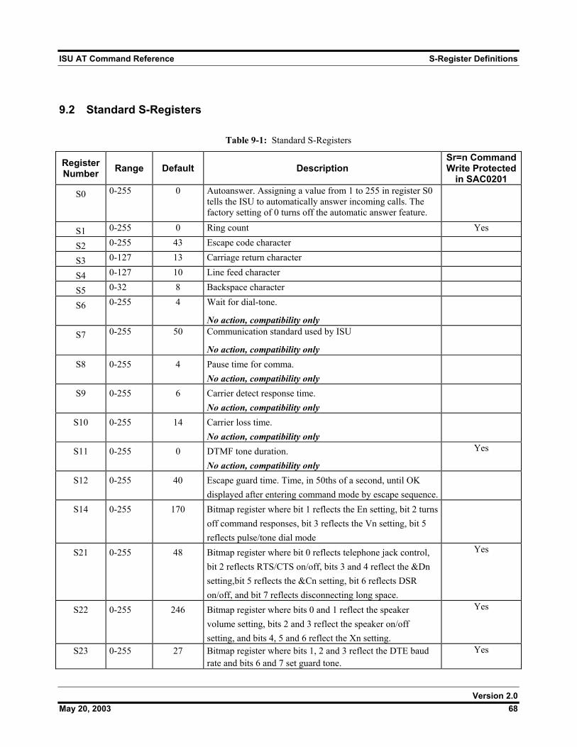
ISU AT Command Reference S-Register Definitions
9.2 Standard S-Registers
Table 9-1: Standard S-Registers
Register Number Range Default Description
Sr=n Command Write Protected
in SAC0201 S0 0-255 0 Autoanswer. Assigning a value from 1 to 255 in register S0
tells the ISU to automatically answer incoming calls. The factory setting of 0 turns off the automatic answer feature.
S1 0-255 0 Ring count Yes
S2 0-255 43 Escape code character
S3 0-127 13 Carriage return character
S4 0-127 10 Line feed character
S5 0-32 8 Backspace character
S6 0-255 4 Wait for dial-tone.
No action, compatibility only
S7 0-255 50 Communication standard used by ISU
No action, compatibility only
S8 0-255 4 Pause time for comma. No action, compatibility only
S9 0-255 6 Carrier detect response time. No action, compatibility only
S10 0-255 14 Carrier loss time. No action, compatibility only
S11 0-255 0 DTMF tone duration. No action, compatibility only
Yes
S12 0-255 40 Escape guard time. Time, in 50ths of a second, until OK displayed after entering command mode by escape sequence.
S14 0-255 170 Bitmap register where bit 1 reflects the En setting, bit 2 turns off command responses, bit 3 reflects the Vn setting, bit 5 reflects pulse/tone dial mode
S21 0-255 48 Bitmap register where bit 0 reflects telephone jack control, bit 2 reflects RTS/CTS on/off, bits 3 and 4 reflect the &Dn setting,bit 5 reflects the &Cn setting, bit 6 reflects DSR on/off, and bit 7 reflects disconnecting long space.
Yes
S22 0-255 246 Bitmap register where bits 0 and 1 reflect the speaker volume setting, bits 2 and 3 reflect the speaker on/off setting, and bits 4, 5 and 6 reflect the Xn setting.
Yes
S23 0-255 27 Bitmap register where bits 1, 2 and 3 reflect the DTE baud rate and bits 6 and 7 set guard tone.
Yes
Version 2.0 May 20, 2003 68
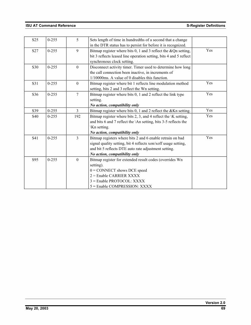
ISU AT Command Reference S-Register Definitions
S25 0-255 5 Sets length of time in hundredths of a second that a change in the DTR status has to persist for before it is recognized.
S27 0-255 9 Bitmap register where bits 0, 1 and 3 reflect the &Qn setting, bit 3 reflects leased line operation setting, bits 4 and 5 reflect synchronous clock setting.
Yes
S30 0-255 0 Disconnect activity timer. Timer used to determine how long the call connection been inactive, in increments of 1/10000ms. A value of 0 disables this function.
S31 0-255 0 Bitmap register where bit 1 reflects line modulation method setting, bits 2 and 3 reflect the Wn setting.
Yes
S36 0-255 7 Bitmap register where bits 0, 1 and 2 reflect the link type setting. No action, compatibility only
Yes
S39 0-255 3 Bitmap register where bits 0, 1 and 2 reflect the &Kn setting. Yes S40 0-255 192 Bitmap register where bits 2, 3, and 4 reflect the \K setting,
and bits 6 and 7 reflect the \An setting, bits 3-5 reflects the \Kn setting. No action, compatibility only
Yes
S41 0-255 3 Bitmap registers where bits 2 and 6 enable retrain on bad signal quality setting, bit 4 reflects xon/xoff usage setting, and bit 5 reflects DTE auto rate adjustment setting. No action, compatibility only
Yes
S95 0-255 0 Bitmap register for extended result codes (overrides Wn setting). 0 = CONNECT shows DCE speed 2 = Enable CARRIER XXXX 3 = Enable PROTOCOL: XXXX 5 = Enable COMPRESSION: XXXX
Version 2.0 May 20, 2003 69
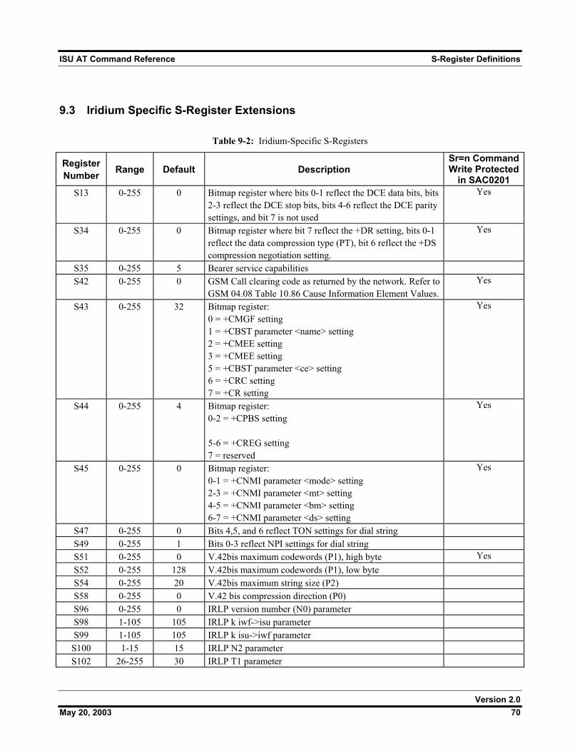
ISU AT Command Reference S-Register Definitions
9.3 Iridium Specific S-Register Extensions
Table 9-2: Iridium-Specific S-Registers
Register Number Range Default Description
Sr=n Command Write Protected
in SAC0201 S13 0-255 0 Bitmap register where bits 0-1 reflect the DCE data bits, bits
2-3 reflect the DCE stop bits, bits 4-6 reflect the DCE parity settings, and bit 7 is not used
Yes
S34 0-255 0 Bitmap register where bit 7 reflect the +DR setting, bits 0-1 reflect the data compression type (PT), bit 6 reflect the +DS compression negotiation setting.
Yes
S35 0-255 5 Bearer service capabilities S42 0-255 0 GSM Call clearing code as returned by the network. Refer to
GSM 04.08 Table 10.86 Cause Information Element Values. Yes
S43 0-255 32 Bitmap register: 0 = +CMGF setting 1 = +CBST parameter <name> setting 2 = +CMEE setting 3 = +CMEE setting 5 = +CBST parameter <ce> setting 6 = +CRC setting 7 = +CR setting
Yes
S44 0-255 4 Bitmap register: 0-2 = +CPBS setting 5-6 = +CREG setting 7 = reserved
Yes
S45 0-255 0 Bitmap register: 0-1 = +CNMI parameter <mode> setting 2-3 = +CNMI parameter <mt> setting 4-5 = +CNMI parameter <bm> setting 6-7 = +CNMI parameter <ds> setting
Yes
S47 0-255 0 Bits 4,5, and 6 reflect TON settings for dial string S49 0-255 1 Bits 0-3 reflect NPI settings for dial string S51 0-255 0 V.42bis maximum codewords (P1), high byte Yes S52 0-255 128 V.42bis maximum codewords (P1), low byte S54 0-255 20 V.42bis maximum string size (P2) S58 0-255 0 V.42 bis compression direction (P0) S96 0-255 0 IRLP version number (N0) parameter S98 1-105 105 IRLP k iwf->isu parameter S99 1-105 105 IRLP k isu->iwf parameter
S100 1-15 15 IRLP N2 parameter S102 26-255 30 IRLP T1 parameter
Version 2.0 May 20, 2003 70
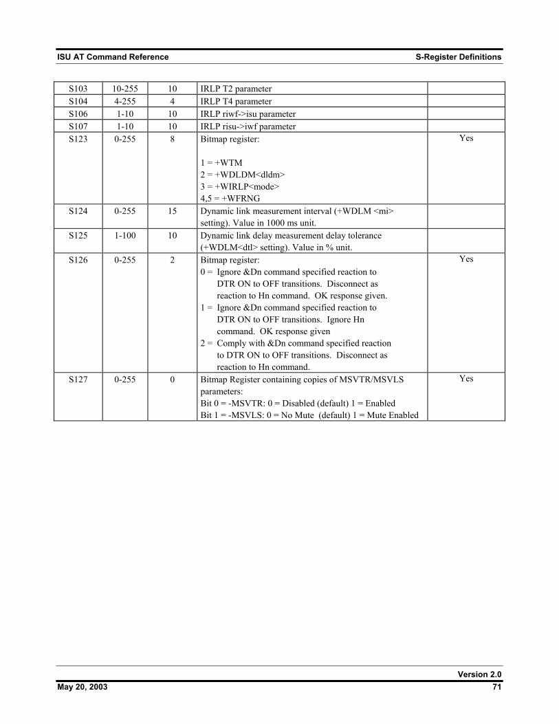
ISU AT Command Reference S-Register Definitions
S103 10-255 10 IRLP T2 parameter S104 4-255 4 IRLP T4 parameter S106 1-10 10 IRLP riwf->isu parameter S107 1-10 10 IRLP risu->iwf parameter S123 0-255 8 Bitmap register:
1 = +WTM 2 = +WDLDM<dldm> 3 = +WIRLP<mode> 4,5 = +WFRNG
Yes
S124 0-255 15 Dynamic link measurement interval (+WDLM <mi> setting). Value in 1000 ms unit.
S125 1-100 10 Dynamic link delay measurement delay tolerance (+WDLM<dtl> setting). Value in % unit.
S126 0-255 2 Bitmap register: 0 = Ignore &Dn command specified reaction to DTR ON to OFF transitions. Disconnect as reaction to Hn command. OK response given. 1 = Ignore &Dn command specified reaction to DTR ON to OFF transitions. Ignore Hn command. OK response given 2 = Comply with &Dn command specified reaction to DTR ON to OFF transitions. Disconnect as reaction to Hn command.
Yes
S127 0-255 0 Bitmap Register containing copies of MSVTR/MSVLS parameters: Bit 0 = -MSVTR: 0 = Disabled (default) 1 = Enabled Bit 1 = -MSVLS: 0 = No Mute (default) 1 = Mute Enabled
Yes
Version 2.0 May 20, 2003 71
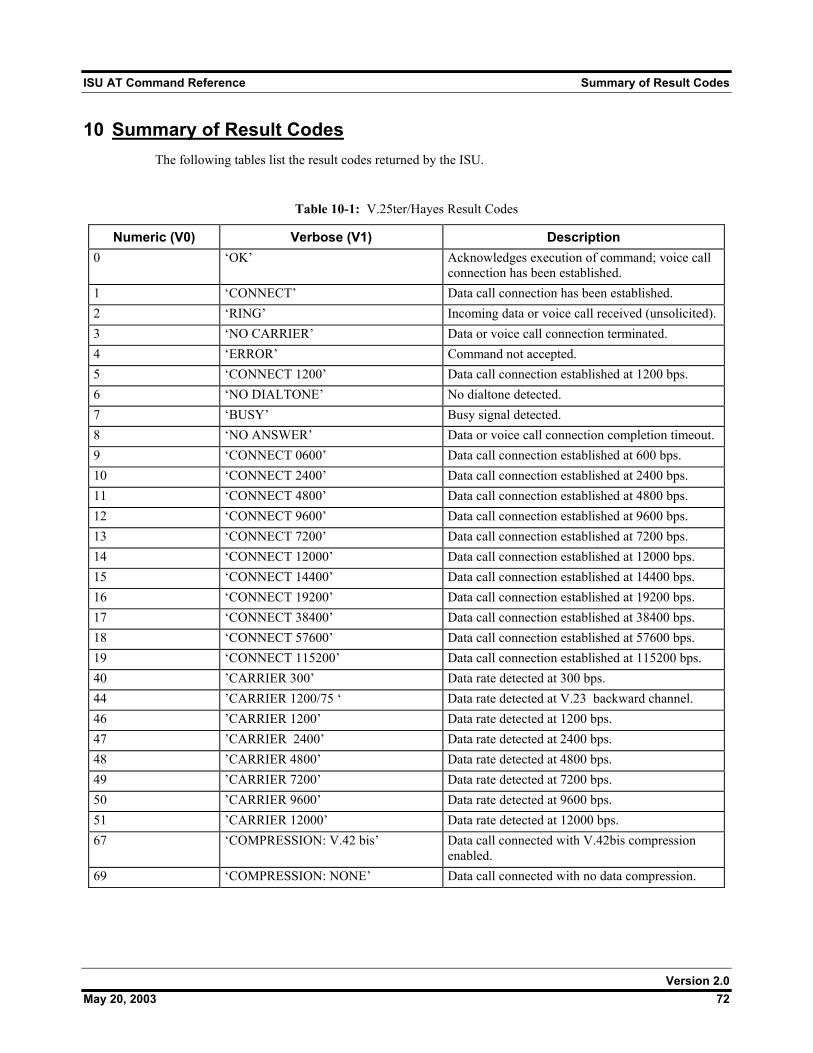
ISU AT Command Reference Summary of Result Codes
10 Summary of Result Codes The following tables list the result codes returned by the ISU.
Table 10-1: V.25ter/Hayes Result Codes
Numeric (V0) Verbose (V1) Description 0 ‘OK’ Acknowledges execution of command; voice call
connection has been established. 1 ‘CONNECT’ Data call connection has been established. 2 ‘RING’ Incoming data or voice call received (unsolicited). 3 ‘NO CARRIER’ Data or voice call connection terminated. 4 ‘ERROR’ Command not accepted. 5 ‘CONNECT 1200’ Data call connection established at 1200 bps. 6 ‘NO DIALTONE’ No dialtone detected. 7 ‘BUSY’ Busy signal detected. 8 ‘NO ANSWER’ Data or voice call connection completion timeout. 9 ‘CONNECT 0600’ Data call connection established at 600 bps. 10 ‘CONNECT 2400’ Data call connection established at 2400 bps. 11 ‘CONNECT 4800’ Data call connection established at 4800 bps. 12 ‘CONNECT 9600’ Data call connection established at 9600 bps. 13 ‘CONNECT 7200’ Data call connection established at 7200 bps. 14 ‘CONNECT 12000’ Data call connection established at 12000 bps. 15 ‘CONNECT 14400’ Data call connection established at 14400 bps. 16 ‘CONNECT 19200’ Data call connection established at 19200 bps. 17 ‘CONNECT 38400’ Data call connection established at 38400 bps. 18 ‘CONNECT 57600’ Data call connection established at 57600 bps. 19 ‘CONNECT 115200’ Data call connection established at 115200 bps. 40 ’CARRIER 300’ Data rate detected at 300 bps. 44 ’CARRIER 1200/75 ‘ Data rate detected at V.23 backward channel. 46 ’CARRIER 1200’ Data rate detected at 1200 bps. 47 ’CARRIER 2400’ Data rate detected at 2400 bps. 48 ’CARRIER 4800’ Data rate detected at 4800 bps. 49 ’CARRIER 7200’ Data rate detected at 7200 bps. 50 ’CARRIER 9600’ Data rate detected at 9600 bps. 51 ’CARRIER 12000’ Data rate detected at 12000 bps. 67 ‘COMPRESSION: V.42 bis’ Data call connected with V.42bis compression
enabled. 69 ‘COMPRESSION: NONE’ Data call connected with no data compression.
Version 2.0 May 20, 2003 72
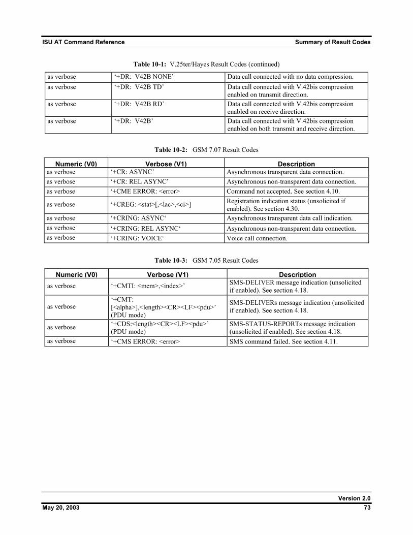
ISU AT Command Reference Summary of Result Codes
Table 10-1: V.25ter/Hayes Result Codes (continued)
as verbose ‘+DR: V42B NONE’ Data call connected with no data compression. as verbose ‘+DR: V42B TD’ Data call connected with V.42bis compression
enabled on transmit direction. as verbose ‘+DR: V42B RD’ Data call connected with V.42bis compression
enabled on receive direction. as verbose ‘+DR: V42B’ Data call connected with V.42bis compression
enabled on both transmit and receive direction.
Table 10-2: GSM 7.07 Result Codes
Numeric (V0) Verbose (V1) Description as verbose ‘+CR: ASYNC’ Asynchronous transparent data connection. as verbose ‘+CR: REL ASYNC’ Asynchronous non-transparent data connection. as verbose ‘+CME ERROR: <error> Command not accepted. See section 4.10.
as verbose ‘+CREG: <stat>[,<lac>,<ci>] Registration indication status (unsolicited if enabled). See section 4.30.
as verbose ‘+CRING: ASYNC‘ Asynchronous transparent data call indication. as verbose ‘+CRING: REL ASYNC‘ Asynchronous non-transparent data connection. as verbose ‘+CRING: VOICE‘ Voice call connection.
Table 10-3: GSM 7.05 Result Codes
Numeric (V0) Verbose (V1) Description as verbose ‘+CMTI: <mem>,<index>’ SMS-DELIVER message indication (unsolicited
if enabled). See section 4.18.
as verbose ‘+CMT: [<alpha>],<length><CR><LF><pdu>’ (PDU mode)
SMS-DELIVERs message indication (unsolicited if enabled). See section 4.18.
as verbose ‘+CDS:<length><CR><LF><pdu>’ (PDU mode)
SMS-STATUS-REPORTs message indication (unsolicited if enabled). See section 4.18.
as verbose ‘+CMS ERROR: <error> SMS command failed. See section 4.11.
Version 2.0 May 20, 2003 73
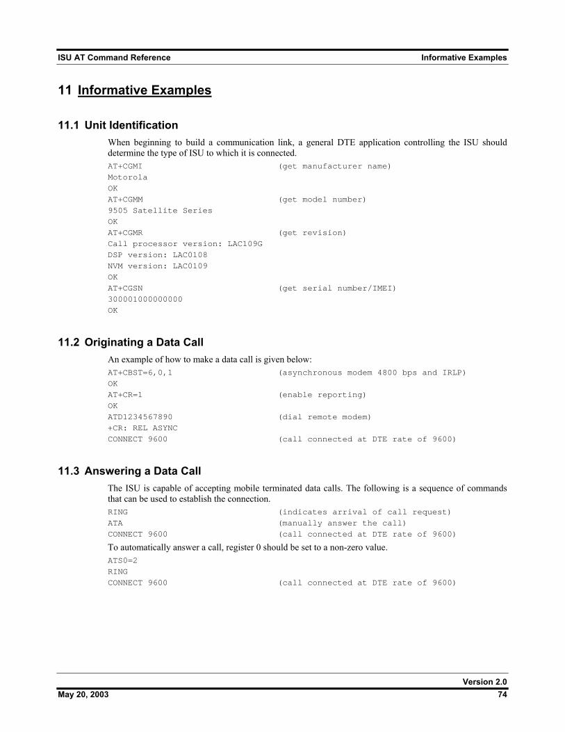
ISU AT Command Reference Informative Examples
11 Informative Examples
11.1 Unit Identification When beginning to build a communication link, a general DTE application controlling the ISU should determine the type of ISU to which it is connected. AT+CGMI (get manufacturer name)
Motorola
OK
AT+CGMM (get model number)
9505 Satellite Series
OK
AT+CGMR (get revision)
Call processor version: LAC109G
DSP version: LAC0108
NVM version: LAC0109
OK
AT+CGSN (get serial number/IMEI)
300001000000000
OK
11.2 Originating a Data Call An example of how to make a data call is given below: AT+CBST=6,0,1 (asynchronous modem 4800 bps and IRLP)
OK
AT+CR=1 (enable reporting)
OK
ATD1234567890 (dial remote modem)
+CR: REL ASYNC
CONNECT 9600 (call connected at DTE rate of 9600)
11.3 Answering a Data Call The ISU is capable of accepting mobile terminated data calls. The following is a sequence of commands that can be used to establish the connection. RING (indicates arrival of call request)
ATA (manually answer the call)
CONNECT 9600 (call connected at DTE rate of 9600)
To automatically answer a call, register 0 should be set to a non-zero value. ATS0=2
RING
CONNECT 9600 (call connected at DTE rate of 9600)
Version 2.0 May 20, 2003 74
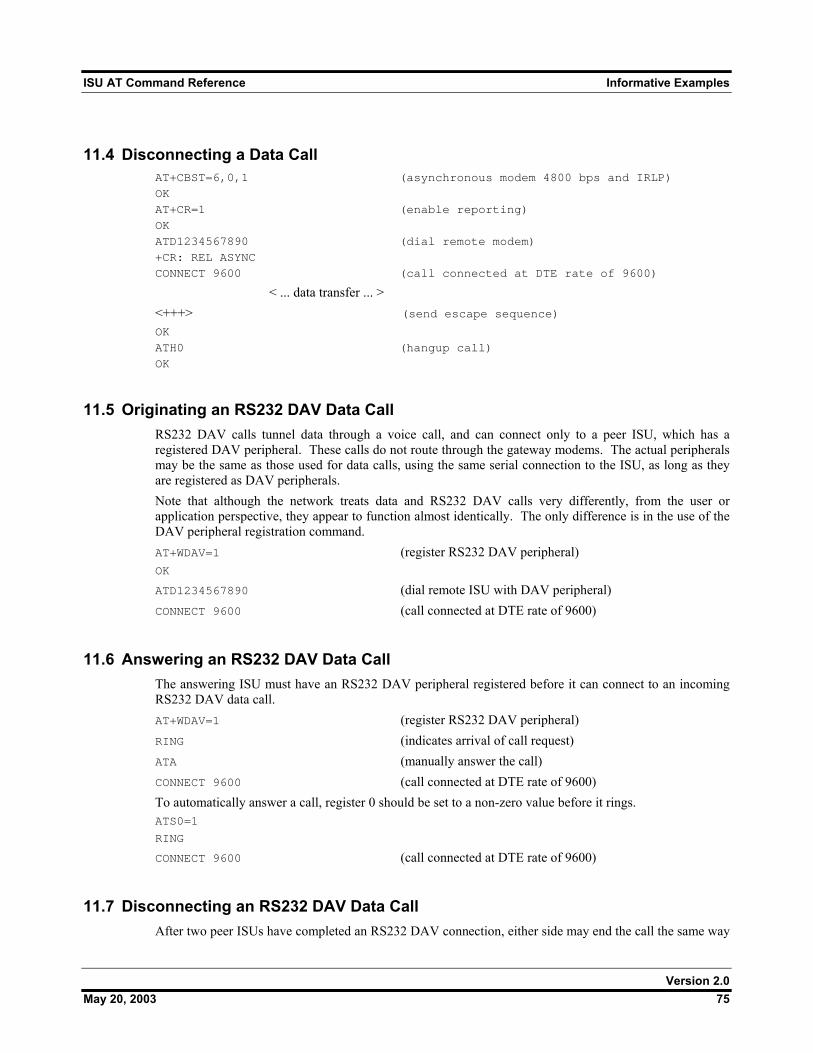
ISU AT Command Reference Informative Examples
11.4 Disconnecting a Data Call AT+CBST=6,0,1 (asynchronous modem 4800 bps and IRLP)
OK
AT+CR=1 (enable reporting)
OK
ATD1234567890 (dial remote modem)
+CR: REL ASYNC
CONNECT 9600 (call connected at DTE rate of 9600)
< ... data transfer ... > <+++> (send escape sequence) OK
ATH0 (hangup call)
OK
11.5 Originating an RS232 DAV Data Call RS232 DAV calls tunnel data through a voice call, and can connect only to a peer ISU, which has a registered DAV peripheral. These calls do not route through the gateway modems. The actual peripherals may be the same as those used for data calls, using the same serial connection to the ISU, as long as they are registered as DAV peripherals. Note that although the network treats data and RS232 DAV calls very differently, from the user or application perspective, they appear to function almost identically. The only difference is in the use of the DAV peripheral registration command. AT+WDAV=1 (register RS232 DAV peripheral) OK
ATD1234567890 (dial remote ISU with DAV peripheral) CONNECT 9600 (call connected at DTE rate of 9600)
11.6 Answering an RS232 DAV Data Call The answering ISU must have an RS232 DAV peripheral registered before it can connect to an incoming RS232 DAV data call. AT+WDAV=1 (register RS232 DAV peripheral) RING (indicates arrival of call request) ATA (manually answer the call) CONNECT 9600 (call connected at DTE rate of 9600) To automatically answer a call, register 0 should be set to a non-zero value before it rings. ATS0=1 RING CONNECT 9600 (call connected at DTE rate of 9600)
11.7 Disconnecting an RS232 DAV Data Call After two peer ISUs have completed an RS232 DAV connection, either side may end the call the same way
Version 2.0 May 20, 2003 75
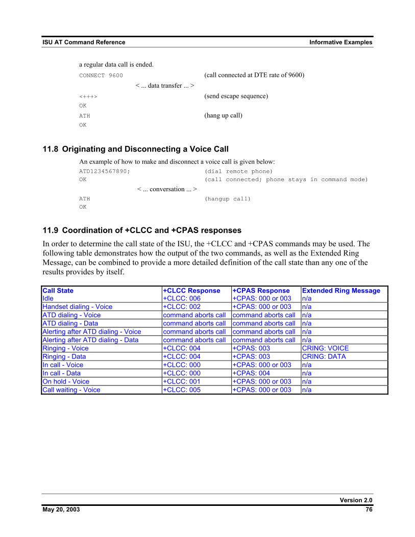
ISU AT Command Reference Informative Examples
a regular data call is ended. CONNECT 9600 (call connected at DTE rate of 9600) < ... data transfer ... > <+++> (send escape sequence) OK ATH (hang up call) OK
11.8 Originating and Disconnecting a Voice Call An example of how to make and disconnect a voice call is given below: ATD1234567890; (dial remote phone)
OK (call connected; phone stays in command mode)
< ... conversation ... > ATH (hangup call)
OK
11.9 Coordination of +CLCC and +CPAS responses In order to determine the call state of the ISU, the +CLCC and +CPAS commands may be used. The following table demonstrates how the output of the two commands, as well as the Extended Ring Message, can be combined to provide a more detailed definition of the call state than any one of the results provides by itself. Call State +CLCC Response +CPAS Response Extended Ring Message Idle +CLCC: 006 +CPAS: 000 or 003 n/a Handset dialing - Voice +CLCC: 002 +CPAS: 000 or 003 n/a ATD dialing - Voice command aborts call command aborts call n/a ATD dialing - Data command aborts call command aborts call n/a Alerting after ATD dialing - Voice command aborts call command aborts call n/a Alerting after ATD dialing - Data command aborts call command aborts call n/a Ringing - Voice +CLCC: 004 +CPAS: 003 CRING: VOICE Ringing - Data +CLCC: 004 +CPAS: 003 CRING: DATA In call - Voice +CLCC: 000 +CPAS: 000 or 003 n/a In call - Data +CLCC: 000 +CPAS: 004 n/a On hold - Voice +CLCC: 001 +CPAS: 000 or 003 n/a Call waiting - Voice +CLCC: 005 +CPAS: 000 or 003 n/a
Version 2.0 May 20, 2003 76
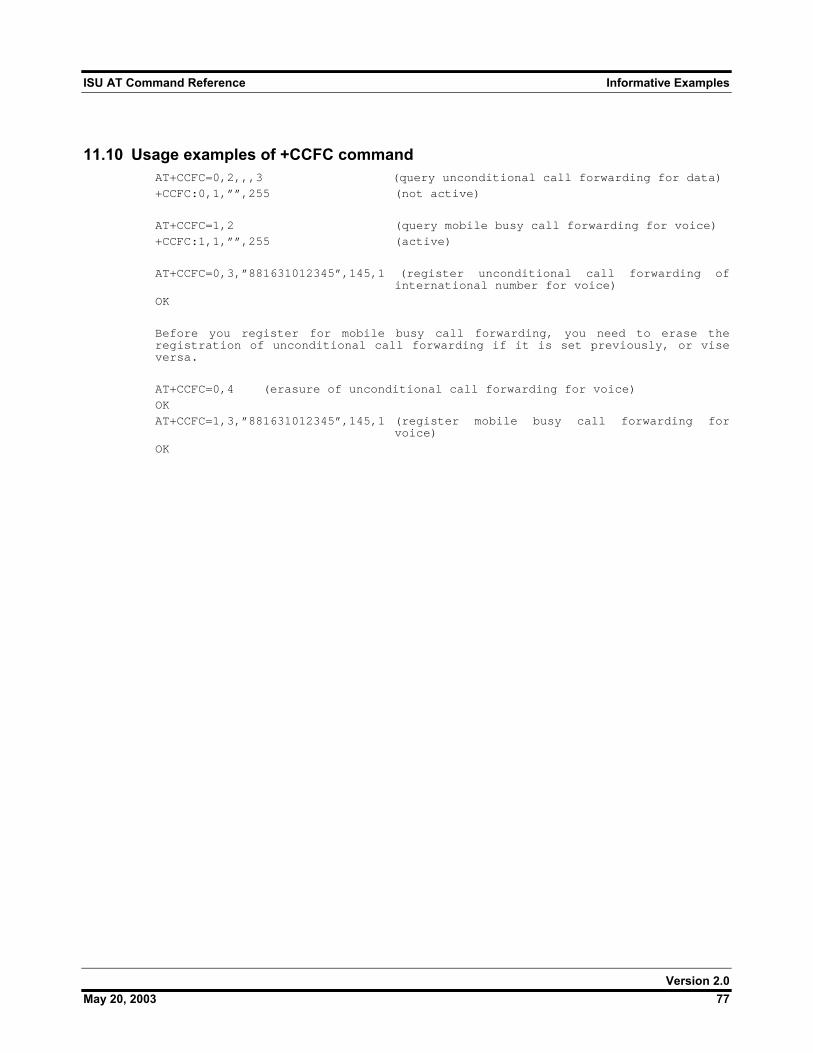
ISU AT Command Reference Informative Examples
Version 2.0 May 20, 2003 77
11.10 Usage examples of +CCFC command AT+CCFC=0,2,,,3 (query unconditional call forwarding for data)
+CCFC:0,1,””,255 (not active)
AT+CCFC=1,2 (query mobile busy call forwarding for voice)
+CCFC:1,1,””,255 (active)
AT+CCFC=0,3,”881631012345”,145,1 (register unconditional call forwarding of international number for voice)
OK
Before you register for mobile busy call forwarding, you need to erase the registration of unconditional call forwarding if it is set previously, or vise versa.
AT+CCFC=0,4 (erasure of unconditional call forwarding for voice)
OK
AT+CCFC=1,3,”881631012345”,145,1 (register mobile busy call forwarding for voice)
OK