lunar communication terminals for nasa exploration missions: … · 2007-08-04 · lunar...
TRANSCRIPT
AIAA ICSSC Conference
American Institute of Aeronautics and Astronautics
061108
1
Lunar Communication Terminals for NASA Exploration Missions: Needs, Operations Concepts and Architectures
Kul B. Bhasin*, Joseph D. Warner.†, and Lynn M. Anderson‡ National Aeronautics & Space Administration, Glenn Research Center, Cleveland, OH, 44135, USA
NASA is conducting architecture studies prior to deploying a series of short- and long-duration human and robotic missions for the exploration of the Moon and Mars under the Vision for Space Exploration Initiative. A key objective of these missions is to establish and expand, through a series of launches, a system of systems approach to exploration capabilities and science return. The systems identified were Crew Exploration Vehicles, crew and cargo launch vehicles, crew EVA suits, crew and cargo landers, habitats, mobility carriers, and small, pressurized rovers. Multiple space communication networks and systems, deployed over time, will support these space exploration systems of systems. Each deployment phase will support interoperability of components and provide 20 years of legacy systems. In this paper, we describe the modular lunar communications terminals needed for the emerging lunar mission operational scenarios. These lunar communication terminals require flexibility for use in stationary, integrated, and mobile environments. They will support links directly to Earth, to lunar relay satellites, to astronauts and to fixed and mobile lunar surface systems. The operating concepts and traffic models are presented for these terminals within variety of lunar scenarios. A preliminary architecture is outlined, providing for suitable long-duration operations in the harsh lunar environment.
I. Introduction One of NASA’s primary goals within President Bush’s Vision for Space Exploration (VSE)1 is to extend human
presence across the solar system, beginning with the return of humans to the Moon no later than 2020, followed by robotic and manned missions to Mars and beyond. In response to the VSE, NASA established the Exploration Systems Mission Directorate (ESMD) whose primary mission is to promote exploration, explore the solar system and beyond, and to develop a sustained human presence on the moon. To provide the necessary end-to-end communications and tracking infrastructure in support of ESMD as well as Science, Shuttle, and International Space Station (ISS) missions2, the Space Operations Mission Directorate (SOMD) created the Space Communications and Navigation (SCaN) program.
Within the ESMD, the Constellation Program (CxP) was established to realize the VSE through the development of space systems and vehicles including the Orion Crew Exploration Vehicle (CEV), the Ares expendable launch vehicle, and the Altair lunar lander. A series of test and support flights involving transportation of cargo and crew in the Orion crew exploration vehicle to the ISS will “spear-head” the mission set now known as Initial Capability. Missions. The transportation of crew and cargo to the Moon will follow. Eventual transportation to Mars and beyond is envisaged. Communication systems which will support these missions that must interoperate include mission control centers, ground terminals, the Orion and Ares vehicles, Earth relay satellites, lunar relay satellites3, lunar surface communication infrastructures, Mars relay satellites, and etc.
NASA has established several phased architecture studies to develop its plans for lunar missions. The Lunar Architecture Team (LAT)4 study was conducted in 2006-2007 with the goal of providing a reference architecture for lunar surface systems and supporting infrastructure. The first phase of the LAT study, LAT Phase 1, provided an analysis of two approaches to the exploration of the lunar surface. One approach involved short sortie missions without the immediate development of an outpost. The other approach investigated the establishment of an outpost prior to focusing on sortie missions. The study concluded with the recommendation of an “outpost first” approach. * Project Manager, NASA Glenn Research Center, 21000 Brookpark Rd., MS 142-4, Associate Fellow. † Senior Scientist,, NASA Glenn Research Center, 21000 Brookpark Rd., MS 54 - 5. ‡ Systems Engineer, Systems Engineering (DSE), NASA Glenn Research Center, 21000 Brookpark Rd., MS 500 - 103.
https://ntrs.nasa.gov/search.jsp?R=20080033045 2020-03-14T00:30:20+00:00Z
AIAA ICSSC Conference
American Institute of Aeronautics and Astronautics
061108
2
The second phase of the LAT study, LAT Phase 2, expanded on the LAT Phase 1 study by considering additional approaches and providing greater depth in design, cost, and implementation detail.
In addition to ESMD’s manned lunar program, NASA’s Science Mission Directorate (SMD) has initiated a lunar science robotic mission initiative with the first mission slated to be a small atmospheric/dust science orbiter with a projected launch date of 2011. Continued missions will establish a geophysical network of mini-landers, with the first pair projected to be launched by 2014. With cooperation from various international space agencies, the SMD is beginning efforts to establish an International Lunar Network (ILN) with the intention of forming a collaborative geophysical network on the lunar surface consisting of 6-8 stations. The ILN may be supported by an International Lunar Relay (ILR) satellite to provide communications and navigation support to international missions on both the near and far side of the lunar surface11.
Architecture requirements provide communication and navigation services to enable the corresponding missions. Architectural elements include the Lunar Communications Terminals (LCTs). On the lunar surface, the LCTs provide the essential function of multiplexing surface traffic onto a broadband link for communication either directly to Earth or through a Lunar Relay Satellite (LRS). The LCTs also de-multiplex data from Earth or the Lunar Relay Satellite (LRS) and distribute this data to the appropriate surface user by potentially using a commercial wireless protocol such as 802.16e. The LCTs also provide the capability of tracking and time services to surface users4.
The communication and navigation infrastructure to support the lunar mission will begin by using a direct-to-earth communication link. The infrastructure will implement the additional architecture elements in a phased approach. As the number of lunar missions and the number of surface assets begin to grow, the LCTs, which can be either attached to a lunar surface mission element or deployed in a fixed location, will be necessary to manage the surface data traffic. Early missions to the lunar surface may be primarily on the near side, while later missions may venture into the far side for science and sortie missions. Providing communications and navigation support to these far-side missions will require the deployment of one or more lunar relay satellites. As the number of lunar surface and orbiting elements grows, additional Earth ground support stations will be established to support the expanding requirements.
Based on identified mission scenarios and requirements in terms of data rates, surface range, and number of required interfaces, three LCT types were conceptualized to satisfy these requirements. They are defined in terms of capacity: small, medium, or large.
Section II discusses the NASA Lunar Mission Scenarios in terms four generic classes: science robotic missions, sortie missions, human mobile missions, and outpost missions, and Section III discusses the communications concepts of operation in terms of these mission scenarios. The definition of Lunar Communication Terminal (LCT) and its types and design drivers are discussed in Section IV, and Section V describes the architectural design of the three types of LCTs.
II. NASA Lunar Mission Scenarios Prior work by NASA’s Lunar Architecture Team, the current Constellation Architecture Team and the Lunar
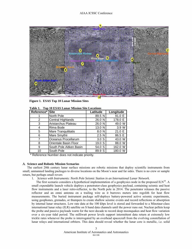
Surface Systems Office defined scenarios and concepts of operation for human exploration focused on build-up of a south pole Outpost*. The Science Mission Directorate is defining scenarios for a companion “Go Anywhere” Lunar Science Program in collaboration with international partners in forums such as the 39th Lunar Planetary Science Conference 6-8. In January 2008, an ad hoc workshop engaged NASA lunar communications experts and lunar scientists in brainstorming lunar communications support for “Go Anywhere” lunar science scenarios drawn from the New Views of the Moon compendium9. Some of those scenarios and CONOPS are included here. Representative scenarios fall into four generic classes: science and robotic missions, sortie missions, human mobile missions, and Outpost missions. The hypothetical scenarios below provide science and exploration context, but are primarily selected to illustrate a range of communications scenarios. Figure 1 and Table 1 illustrate the Top 10 Lunar mission landing sites as determined by the Exploration Systems Architecture Study (ESAS), which was NASA’s first lunar architecture team funded and lead by NASA headquarters.
* Schier, J. et al (Lunar Architecture Team), “LAT2 Communications and Navigation Focus Element Final Report”, NASA internal report (unpublished), August 4, 2007.
AIAA ICSSC Conference
American Institute of Aeronautics and Astronautics
061108
3
A. Science and Robotic Mission Scenarios The earliest 20th century lunar surface missions are robotic missions that deploy scientific instruments from
small, unmanned landing packages to diverse locations on the Moon’s near and far sides. There is no crew or sample return, but perhaps small rovers
1. Science with Instruments: North Pole Seismic Station in an International Lunar Network. The first scenario considers a hypothetical implementation of a geophysics node in the proposed ILN10. A
small expendable launch vehicle deploys a penetrator-class geophysics payload, containing seismic and heat flow instruments and a laser retro-reflector, to the North pole in 2014. The penetrator releases the passive reflector and an omni antenna on a trailing wire as it burrows meters into regolith for heat flow measurements. The buried instrument package self-deploys battery-powered active seismic experiments, using geophones, grenades, or thumpers to create shallow seismic events and record reflections or absorption by internal lunar structures. Low rate data at the 100 kbps level is stored and forwarded to a Minotaur-class international lunar relay (ILR) satellite on S band data channels until the power runs out. Nuclear pellets keep the probe and passive payloads warm for the next decade to record deep moonquakes and heat flow variation over a six-year tidal period. The milliwatt power levels support intermittent data return at extremely low trickle rates whenever the probe is interrogated by an overhead spacecraft from the evolving constellation of lunar relays and international orbiters. This data should reveal whether the lunar core is metallic, i.e. solid
Figure 1. ESAS Top 10 Lunar Mission Sites
Table 1. Top 10 ESAS Lunar Mission Site Locations Reference* Site
1 North Pole 89.5 N 91.0 E2 Central Highlands 26.0 N 178.0 E3 Aristarchus Plateau 26.0 N 49.0 W4 Rima Bode 13.0 N 3.9 W5 Mare Tranquilitatis 8.0 N 21.0 E6 Mare Smythii 2.5 N 86.5 E7 Oceanus Procellarum 3.0 S 43.0 W8 Orientale Basin Floor 19.0 S 88.0 W9 South Pole Aitken Basin 54.0 S 162.0 W10 South Pole 89.9 S 180.0 W
Latitude Longitude
* Reference Number does not indicate priority.
AIAA ICSSC Conference
American Institute of Aeronautics and Astronautics
061108
4
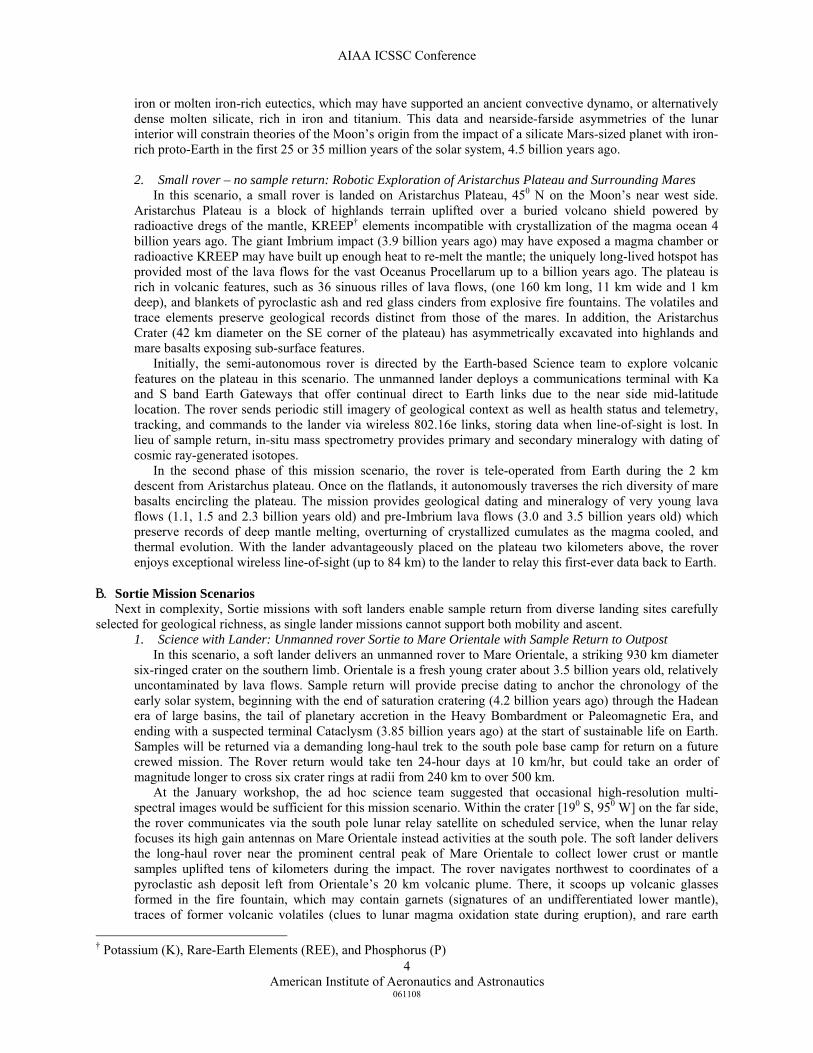
iron or molten iron-rich eutectics, which may have supported an ancient convective dynamo, or alternatively dense molten silicate, rich in iron and titanium. This data and nearside-farside asymmetries of the lunar interior will constrain theories of the Moon’s origin from the impact of a silicate Mars-sized planet with iron-rich proto-Earth in the first 25 or 35 million years of the solar system, 4.5 billion years ago. 2. Small rover – no sample return: Robotic Exploration of Aristarchus Plateau and Surrounding Mares
In this scenario, a small rover is landed on Aristarchus Plateau, 450 N on the Moon’s near west side. Aristarchus Plateau is a block of highlands terrain uplifted over a buried volcano shield powered by radioactive dregs of the mantle, KREEP† elements incompatible with crystallization of the magma ocean 4 billion years ago. The giant Imbrium impact (3.9 billion years ago) may have exposed a magma chamber or radioactive KREEP may have built up enough heat to re-melt the mantle; the uniquely long-lived hotspot has provided most of the lava flows for the vast Oceanus Procellarum up to a billion years ago. The plateau is rich in volcanic features, such as 36 sinuous rilles of lava flows, (one 160 km long, 11 km wide and 1 km deep), and blankets of pyroclastic ash and red glass cinders from explosive fire fountains. The volatiles and trace elements preserve geological records distinct from those of the mares. In addition, the Aristarchus Crater (42 km diameter on the SE corner of the plateau) has asymmetrically excavated into highlands and mare basalts exposing sub-surface features.
Initially, the semi-autonomous rover is directed by the Earth-based Science team to explore volcanic features on the plateau in this scenario. The unmanned lander deploys a communications terminal with Ka and S band Earth Gateways that offer continual direct to Earth links due to the near side mid-latitude location. The rover sends periodic still imagery of geological context as well as health status and telemetry, tracking, and commands to the lander via wireless 802.16e links, storing data when line-of-sight is lost. In lieu of sample return, in-situ mass spectrometry provides primary and secondary mineralogy with dating of cosmic ray-generated isotopes.
In the second phase of this mission scenario, the rover is tele-operated from Earth during the 2 km descent from Aristarchus plateau. Once on the flatlands, it autonomously traverses the rich diversity of mare basalts encircling the plateau. The mission provides geological dating and mineralogy of very young lava flows (1.1, 1.5 and 2.3 billion years old) and pre-Imbrium lava flows (3.0 and 3.5 billion years old) which preserve records of deep mantle melting, overturning of crystallized cumulates as the magma cooled, and thermal evolution. With the lander advantageously placed on the plateau two kilometers above, the rover enjoys exceptional wireless line-of-sight (up to 84 km) to the lander to relay this first-ever data back to Earth.
B. Sortie Mission Scenarios Next in complexity, Sortie missions with soft landers enable sample return from diverse landing sites carefully
selected for geological richness, as single lander missions cannot support both mobility and ascent. 1. Science with Lander: Unmanned rover Sortie to Mare Orientale with Sample Return to Outpost
In this scenario, a soft lander delivers an unmanned rover to Mare Orientale, a striking 930 km diameter six-ringed crater on the southern limb. Orientale is a fresh young crater about 3.5 billion years old, relatively uncontaminated by lava flows. Sample return will provide precise dating to anchor the chronology of the early solar system, beginning with the end of saturation cratering (4.2 billion years ago) through the Hadean era of large basins, the tail of planetary accretion in the Heavy Bombardment or Paleomagnetic Era, and ending with a suspected terminal Cataclysm (3.85 billion years ago) at the start of sustainable life on Earth. Samples will be returned via a demanding long-haul trek to the south pole base camp for return on a future crewed mission. The Rover return would take ten 24-hour days at 10 km/hr, but could take an order of magnitude longer to cross six crater rings at radii from 240 km to over 500 km.
At the January workshop, the ad hoc science team suggested that occasional high-resolution multi-spectral images would be sufficient for this mission scenario. Within the crater [190 S, 950 W] on the far side, the rover communicates via the south pole lunar relay satellite on scheduled service, when the lunar relay focuses its high gain antennas on Mare Orientale instead activities at the south pole. The soft lander delivers the long-haul rover near the prominent central peak of Mare Orientale to collect lower crust or mantle samples uplifted tens of kilometers during the impact. The rover navigates northwest to coordinates of a pyroclastic ash deposit left from Orientale’s 20 km volcanic plume. There, it scoops up volcanic glasses formed in the fire fountain, which may contain garnets (signatures of an undifferentiated lower mantle), traces of former volcanic volatiles (clues to lunar magma oxidation state during eruption), and rare earth
† Potassium (K), Rare-Earth Elements (REE), and Phosphorus (P)
AIAA ICSSC Conference
American Institute of Aeronautics and Astronautics
061108
5
elements (fingerprints of former mantle composition). Rover-mounted payloads take measurements from a nearby major low gravity anomaly (subsurface mass deficit) created by buckling of the exceptionally thin crust with a thickness of 17 km.
In this scenario, Mission Control assists in reconnoitering the best southeast site to cross the first crater ring; Clementine Earthshine images indicate three km steep-walled cliffs to the East and worse to the West. Reaching the eastern highlands ejecta curtain, the rover scoops fused brecchia of shattered rock that may contain microscopic samples of older deeper rocks uncontaminated by volcanism. The deepest coarsest ejecta are nearest the rim. The rover progresses outward scooping and time stamping samples in reverse stratigraphic order. Once out of the crater on the southern limb, the rover crosses to the nearside to acquire intermittent direct-to-Earth communications for return of stored imagery and navigation during the 2400 km return of valuable geological samples to base camp. 2. Human Sortie to Farside Central Highlands for Sample Return
In this difficult mission scenario, a crewed sortie might venture to the rugged farside central highlands. As the magma ocean of the molten Moon began to cool and crystallize 4.5 billion years ago, low density silicate-rich cumulates from the Mars-sized Impactor floated up to form the feldspathic highlands while denser iron and magnesium-rich cumulates stripped from proto-Earth sank forming core and mantle. The highlands preserve the Moon’s ancient crust uncontaminated by mare volcanism. Billions of years of asteroid impacts left fused brecchia of ancient shattered rocks. With human field observation, brecchia may be found with microscopic samples of the oldest mares dating back 4.2 billion years.
The farside highlands mission requires a lunar relay, and is too far north for much coverage from lunar relays that are in elliptical orbits with apogee over the south pole outpost. The ad hoc science team was willing to wait until the constellation included a northern relay to support HDTV. During the mission, ground-based science teams will orient the lunar crew with daily science briefs of annotated moderate resolution imagery, preferable in video. During EVA fieldwork, the Earth team will view the crew’s high definition imagery, relayed through the lander in near real-time, and can engage the crew in live discussions to optimize sample collection. Samples are tagged by RFID and time stamped. High-resolution scientific imagery is returned by store-and-forward at lower frame rates. The crew leave behind heat flow instruments, part of the International Geophysics Network, which can be interrogated by later satellites in store and dump mode.
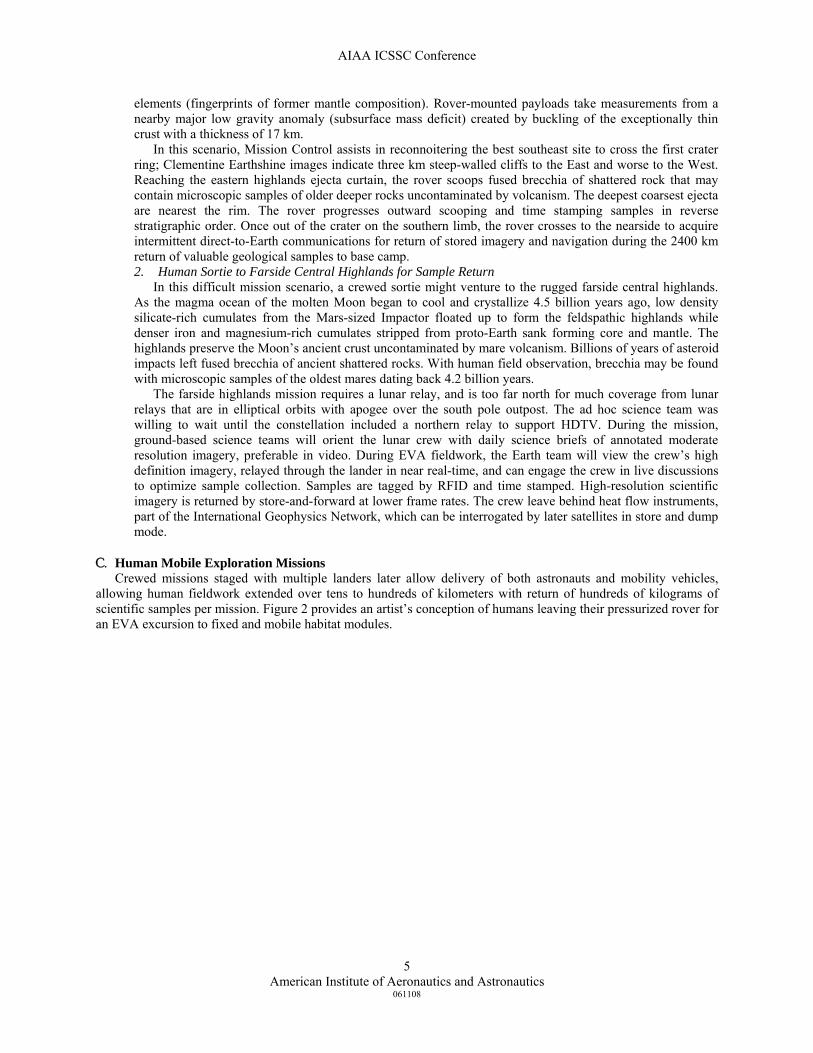
C. Human Mobile Exploration Missions Crewed missions staged with multiple landers later allow delivery of both astronauts and mobility vehicles,
allowing human fieldwork extended over tens to hundreds of kilometers with return of hundreds of kilograms of scientific samples per mission. Figure 2 provides an artist’s conception of humans leaving their pressurized rover for an EVA excursion to fixed and mobile habitat modules.
AIAA ICSSC Conference
American Institute of Aeronautics and Astronautics
061108
6
1. Search for Old Mare Basalts in Dark Halo Craters near the Outpost
In the early years of the south pole outpost, there is no habitat, and the crew lives out of the lander or small pressurized rovers during excursions. In this scenario, a crewed lander brings four astronauts to a south pole outpost that already has two small pressurized rovers and not much else. The rovers are mounted on the cargo pallet of the prior cargo lander, which also carries a mobile solar array on a towable chassis and crane-like unloading equipment. The crew’s first task is to use the cranes to unload the pallet from the lander and drive the rovers off, pulling the mobile solar array. This task is supported by a modest communications hub, the fixed base radio, mounted on the lander.
Once the cargo lander is unloaded, the crew takes both small pressurized rovers, the mobile solar array and crane, on an excursion to search for very old mare basalts in dark halo craters near the outpost. This terrain is typified by Scott, Amundsen, and Cabeus craters, and terrain below Malapert Mountain. The lander and fixed base remain at the rim of Shackleton Crater, a site optimal for solar illumination. Recent Goldstone radar antenna data shows that the terrain slopes downhill from the crater rim at about twenty degrees and tapers to relatively flat terrain two kilometers below. With 2 km terrain advantage, the fixed base wireless sector antennas on the lander, have a practical line-of-sight range of about 38 kilometers, allowing continual wireless communications (at 10-20 Mbps) during exploration into four or five basins nearest the outpost. Some of the craters have two-kilometer rims, which obstruct wireless line-of-sight, so the crew will park the mobile solar array and one rover as a repeater to extend wireless coverage. Unfortunately, if the lead rover becomes stuck in the shallow crater, some of the crew may lose contact in terrain and become disoriented during the walk-back. This would force them to rely on their EVA suit radios to communicate with Mission Control through a lunar relay satellite. 2. South Pole Aitkens Basin
In this mission scenario, an experienced crew undertakes an extended sortie landing and long-distance excursion to explore the floor of south pole-Aitkens Basin. Aitkens Basin is a vast 2500 km diameter crater covering the southern far side (30°S, 150°W to 130°E), the oldest topographically preserved basin on the
Figure 2. Artists concept of humans performing EVA to fixed and mobile habitat modules.
AIAA ICSSC Conference
American Institute of Aeronautics and Astronautics
061108
7
Moon and deepest in the solar system. Landing and ascent occurs on the basin floor rather than attempting a return to the outpost. The crew drive their rovers to collect bulk and sieved samples from the basin floor where the upper crust may have been stripped off to reveal first-ever samples of the Moon’s lower crust. These samples are dated to test the Cataclysm hypothesis. The crew will search for impact melts containing first-ever mantle samples that shed light on thermal evolution of the interior and constrain the computational Giant Impact models. Their best possibilities to obtain mantle rocks may include areas excavated across stratigraphic layers and in craters within the crater. The crew will need their rovers to reach the mega-regolith of ejecta where they may find xenolithic fragments of mantle rock. Measured fieldwork will be necessary to provide the geological context and increase the odds of locating ancient samples such as buried cryptomaria. Accurate navigational ties to lunar maps, time stamping, and RFID tagging of samples will be essential to the accuracy of the fieldwork in this scenario.
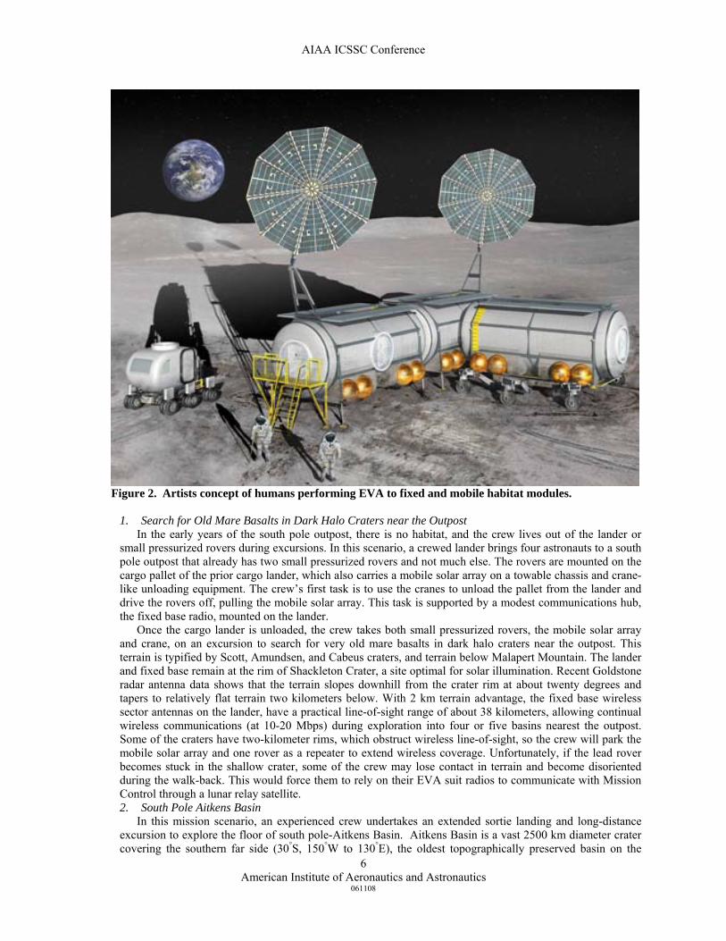
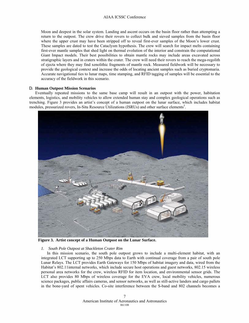
D. Human Outpost Mission Scenarios Eventually repeated missions to the same base camp will result in an outpost with the power, habitation
elements, logistics, and mobility vehicles to allow extended human stay and complex geological operations such as trenching. Figure 3 provides an artist’s concept of a human outpost on the lunar surface, which includes habitat modules, pressurized rovers, In-Situ Resource Utilizations (ISRUs) and other surface elements5.
1. South Pole Outpost at Shackleton Crater Rim
In this mission scenario, the south pole outpost grows to include a multi-element habitat, with an integrated LCT supporting up to 250 Mbps data to Earth with continual coverage from a pair of south pole Lunar Relays. The LCT provides Earth Gateways for 150 Mbps of habitat imagery and data, wired from the Habitat’s 802.11internal networks, which include secure host operations and guest networks, 802.15 wireless personal area networks for the crew, wireless RFID for item location, and environmental sensor grids. The LCT also provides 80 Mbps of wireless coverage for the EVA crew, local mobility vehicles, numerous science packages, public affairs cameras, and sensor networks, as well as still-active landers and cargo pallets in the bone-yard of spent vehicles. Co-site interference between the S-band and 802 channels becomes a
Figure 3. Artist concept of a Human Outpost on the Lunar Surface.
AIAA ICSSC Conference
American Institute of Aeronautics and Astronautics
061108
8
concern in this scenario, as well as multi-path from the growing number of surface structures, and interoperability and security with the arrival of international visitors and commercial infrastructure providers.
The central hub is essential for the communications architecture so that numerous surface units are not competing for available channels of the LRS. The LCT efficiently multiplexes and routes messages on the Moon, reducing latency for tele-operations, a key step towards self-sufficiency for Mars. The hub continues to provide local time generation with atomic clocks and ultra stable oscillators to assure synchronization of communications time slots, and provides primary navigation services to enable incoming landers to achieve precision positioning amid outpost congestion. With the arrival of crab-like ATHLETE legs that carry whole pallets with solar arrays and habitat modules, the question in this scenario is whether the entire habitat can undertake long-range excursions in a caravan of mobility vehicles and walking infrastructure.
The communication and navigation architecture serves the needs of the completed initial outpost as well as an arbitrary number of sortie locations anywhere on the Moon with communications, tracking, and time services on a largely unscheduled (i.e., on-demand) basis. Based on a number of criteria, preliminary site selection places the outpost at a north or south polar location. The LAT study selected the rim of Shackleton Crater at the south pole for the reference architecture. The Outpost will consist of 1-5 habitable elements connected to form one pressurized Habitat with an internal Local Area Network (LAN). The Outpost will also include nearby Solar Power Units (SPU) and associated Makeup Power Units (MPU) to provide continuous power through day and night operations. A pair of pressurized rovers will enable four crew to conduct two or four person EVAs requiring communications and surface navigation for up to two PRs and four crew simultaneously.
In this scenario, excursions up to hundreds of kilometers are envisioned, requiring more precise surface navigation than was needed on Apollo. Several robotic Surface Mobility Carriers (SMC) may also be used in cooperative operations with the crew. ISRU will require a combination of regolith excavation using SMCs equipped with digging attachments, regolith transportation using SMCs equipped with holding bins, regolith processing using small processing plants, and product (e.g., oxygen) transportation using SMCs carrying tanks in order to replenish storage tanks. Crewed operations build up from initial seven-day stays during early construction to 180-day stays with full logistics support.
2. Scientific Trenching and In-Situ Resource Utilization
The final scenario concerns crew and semi-autonomous operations of heavy-duty equipment (mobility vehicles with excavators and drills) several kilometers from the outpost. Tasks include trenching several meters into selected sites to find ancient regolith (a solar history record) between layers of datable mare basalts. The crew would set up demonstrations and pilot projects to produce oxygen from regolith. Rovers would scoop lunar material, sense a full load, transport and dump into autonomous processors. Once the load is processed, mobility vehicles would receive a wireless call to transport full tanks to the habitat for outpost use. In this scenario, the old lander fixed-base radio, which served as a communications hub for the early outpost, has been moved to this ISRU site along with a spare solar array from a spent lander, to provide a permanent second node on the lunar network. The crew will explore permanently shadowed craters at the south pole, and identify several additional remote sites where it may be profitable to excavate for comet-derived volatiles, possibly including helium-3. Excavations to assess the properties and variation of polar hydrogen, could reveal an exploitable resource for the growing outpost.
III. Communication Operational Concepts for the Scenarios The previous section provided specific visions for the four general lunar mission scenarios discussed in this
paper. In this section, the concepts for communications for those four missions are given. These concepts focus on the communication networking among surface elements and communicating off the lunar surface to the LRS or to Earth. In LAT2 the links to the Earth or to the LRS were made the same. This was done through sizing the relative area of the dishes on LRS and on Earth to be the approximately the relative distance squared between the lunar surface to LRS and to Earth. Essentially, lunar surface users would have the same quality of link if they would be communicating to LRS or to Earth. The concept of operations for navigation on the lunar surface will be limited to the communication path and frequencies for surface users. The full concept of navigation on the lunar surface involves much more than coherent ranging and Doppler measurements and is left for a separate paper.
A. Science and Robotic Mission Scenarios
AIAA ICSSC Conference
American Institute of Aeronautics and Astronautics
061108
9
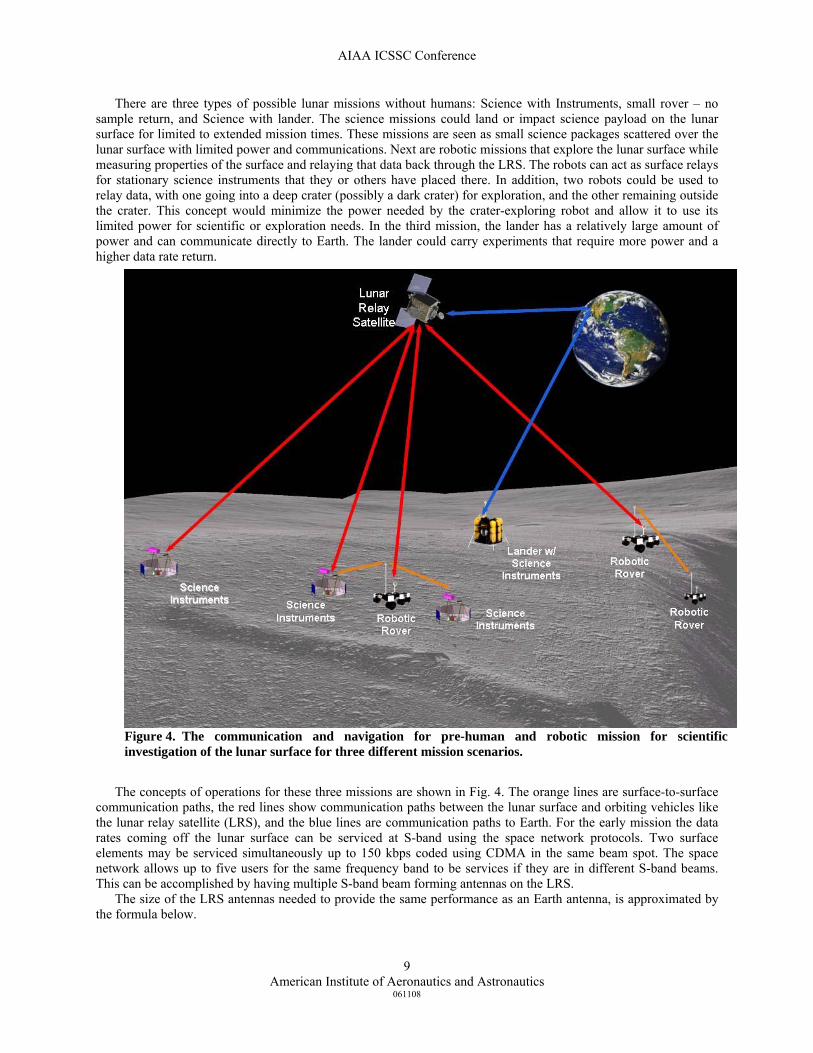
There are three types of possible lunar missions without humans: Science with Instruments, small rover – no sample return, and Science with lander. The science missions could land or impact science payload on the lunar surface for limited to extended mission times. These missions are seen as small science packages scattered over the lunar surface with limited power and communications. Next are robotic missions that explore the lunar surface while measuring properties of the surface and relaying that data back through the LRS. The robots can act as surface relays for stationary science instruments that they or others have placed there. In addition, two robots could be used to relay data, with one going into a deep crater (possibly a dark crater) for exploration, and the other remaining outside the crater. This concept would minimize the power needed by the crater-exploring robot and allow it to use its limited power for scientific or exploration needs. In the third mission, the lander has a relatively large amount of power and can communicate directly to Earth. The lander could carry experiments that require more power and a higher data rate return.
The concepts of operations for these three missions are shown in Fig. 4. The orange lines are surface-to-surface
communication paths, the red lines show communication paths between the lunar surface and orbiting vehicles like the lunar relay satellite (LRS), and the blue lines are communication paths to Earth. For the early mission the data rates coming off the lunar surface can be serviced at S-band using the space network protocols. Two surface elements may be serviced simultaneously up to 150 kbps coded using CDMA in the same beam spot. The space network allows up to five users for the same frequency band to be services if they are in different S-band beams. This can be accomplished by having multiple S-band beam forming antennas on the LRS.
The size of the LRS antennas needed to provide the same performance as an Earth antenna, is approximated by the formula below.
Figure 4. The communication and navigation for pre-human and robotic mission for scientific investigation of the lunar surface for three different mission scenarios.
AIAA ICSSC Conference
American Institute of Aeronautics and Astronautics
061108
10
1/ 2
390000s e
s ee s
TRD Dkm T
ηη
⎛ ⎞∗⎛ ⎞= ∗ ∗⎜ ⎟⎜ ⎟ ∗⎝ ⎠ ⎝ ⎠
Where Ds is the minimum diameter on LRS or CEV, De is the diameter used on the lunar surface, and R is the maximum range in kilometers from the lunar surface to the orbiting asset. The 390,000 km is the distance used between the Earth and the Moon. Ts is the system noise temperature of the satellite looking at the lunar surface while Te is the system noise temperature of the Earth ground terminal looking at the Moon. ηe is the efficiency of the Earth antenna and ηs is the efficiency of the LRS antenna. To have the satellite reduce the communication power or mass burden on lunar communication, the LRS antenna must be larger than Ds.
B. Sortie Mission Scenarios
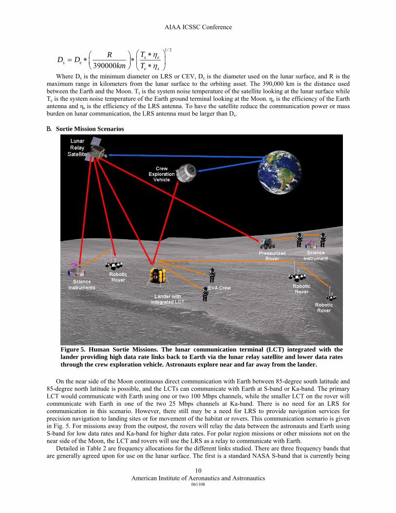
On the near side of the Moon continuous direct communication with Earth between 85-degree south latitude and
85-degree north latitude is possible, and the LCTs can communicate with Earth at S-band or Ka-band. The primary LCT would communicate with Earth using one or two 100 Mbps channels, while the smaller LCT on the rover will communicate with Earth in one of the two 25 Mbps channels at Ka-band. There is no need for an LRS for communication in this scenario. However, there still may be a need for LRS to provide navigation services for precision navigation to landing sites or for movement of the habitat or rovers. This communication scenario is given in Fig. 5. For missions away from the outpost, the rovers will relay the data between the astronauts and Earth using S-band for low data rates and Ka-band for higher data rates. For polar region missions or other missions not on the near side of the Moon, the LCT and rovers will use the LRS as a relay to communicate with Earth.
Detailed in Table 2 are frequency allocations for the different links studied. There are three frequency bands that are generally agreed upon for use on the lunar surface. The first is a standard NASA S-band that is currently being
Figure 5. Human Sortie Missions. The lunar communication terminal (LCT) integrated with the lander providing high data rate links back to Earth via the lunar relay satellite and lower data rates through the crew exploration vehicle. Astronauts explore near and far away from the lander.
AIAA ICSSC Conference
American Institute of Aeronautics and Astronautics
061108
11
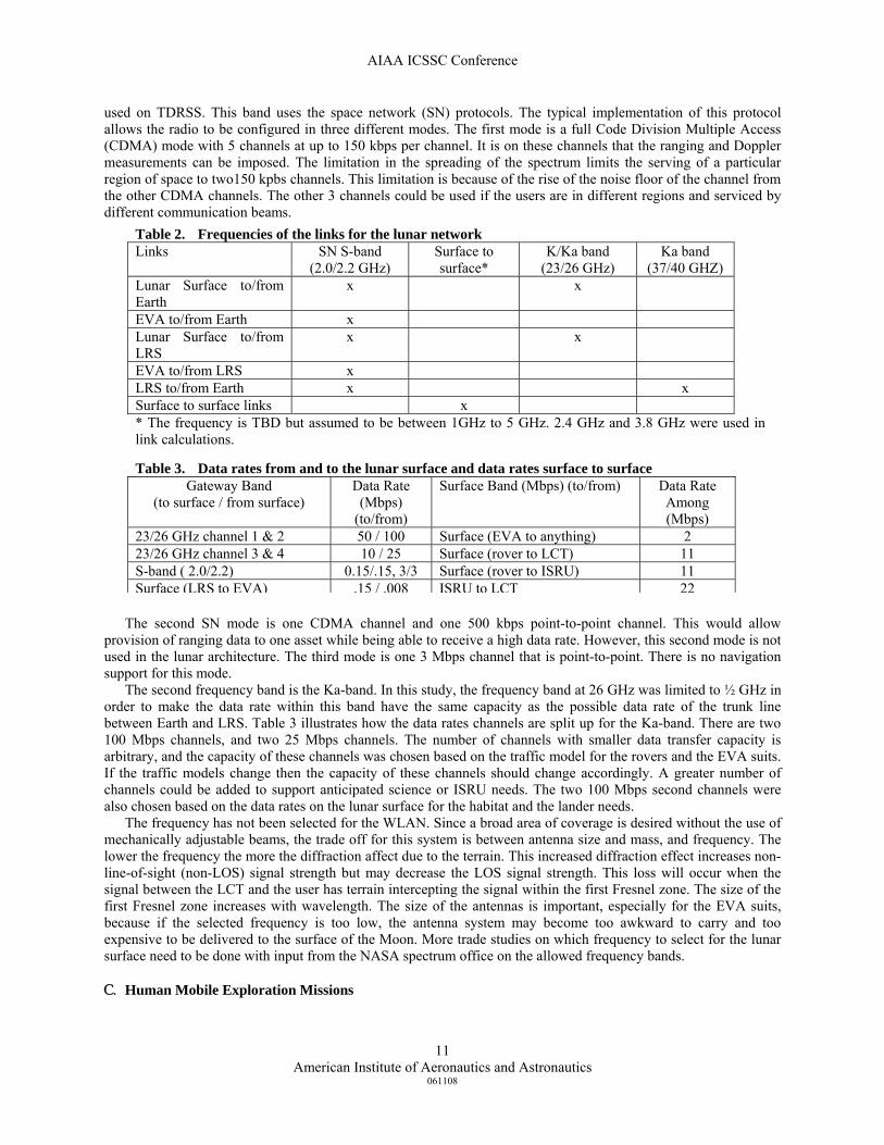
used on TDRSS. This band uses the space network (SN) protocols. The typical implementation of this protocol allows the radio to be configured in three different modes. The first mode is a full Code Division Multiple Access (CDMA) mode with 5 channels at up to 150 kbps per channel. It is on these channels that the ranging and Doppler measurements can be imposed. The limitation in the spreading of the spectrum limits the serving of a particular region of space to two150 kpbs channels. This limitation is because of the rise of the noise floor of the channel from the other CDMA channels. The other 3 channels could be used if the users are in different regions and serviced by different communication beams.
The second SN mode is one CDMA channel and one 500 kbps point-to-point channel. This would allow
provision of ranging data to one asset while being able to receive a high data rate. However, this second mode is not used in the lunar architecture. The third mode is one 3 Mbps channel that is point-to-point. There is no navigation support for this mode.
The second frequency band is the Ka-band. In this study, the frequency band at 26 GHz was limited to ½ GHz in order to make the data rate within this band have the same capacity as the possible data rate of the trunk line between Earth and LRS. Table 3 illustrates how the data rates channels are split up for the Ka-band. There are two 100 Mbps channels, and two 25 Mbps channels. The number of channels with smaller data transfer capacity is arbitrary, and the capacity of these channels was chosen based on the traffic model for the rovers and the EVA suits. If the traffic models change then the capacity of these channels should change accordingly. A greater number of channels could be added to support anticipated science or ISRU needs. The two 100 Mbps second channels were also chosen based on the data rates on the lunar surface for the habitat and the lander needs.
The frequency has not been selected for the WLAN. Since a broad area of coverage is desired without the use of mechanically adjustable beams, the trade off for this system is between antenna size and mass, and frequency. The lower the frequency the more the diffraction affect due to the terrain. This increased diffraction effect increases non-line-of-sight (non-LOS) signal strength but may decrease the LOS signal strength. This loss will occur when the signal between the LCT and the user has terrain intercepting the signal within the first Fresnel zone. The size of the first Fresnel zone increases with wavelength. The size of the antennas is important, especially for the EVA suits, because if the selected frequency is too low, the antenna system may become too awkward to carry and too expensive to be delivered to the surface of the Moon. More trade studies on which frequency to select for the lunar surface need to be done with input from the NASA spectrum office on the allowed frequency bands.
C. Human Mobile Exploration Missions
Table 2. Frequencies of the links for the lunar network Links SN S-band
(2.0/2.2 GHz) Surface to surface*
K/Ka band (23/26 GHz)
Ka band (37/40 GHZ)
Lunar Surface to/from Earth
x x
EVA to/from Earth x Lunar Surface to/from LRS
x x
EVA to/from LRS x LRS to/from Earth x x Surface to surface links x * The frequency is TBD but assumed to be between 1GHz to 5 GHz. 2.4 GHz and 3.8 GHz were used in link calculations.
Table 3. Data rates from and to the lunar surface and data rates surface to surface Gateway Band
(to surface / from surface) Data Rate
(Mbps) (to/from)
Surface Band (Mbps) (to/from) Data Rate Among (Mbps)
23/26 GHz channel 1 & 2 50 / 100 Surface (EVA to anything) 2 23/26 GHz channel 3 & 4 10 / 25 Surface (rover to LCT) 11 S-band ( 2.0/2.2) 0.15/.15, 3/3 Surface (rover to ISRU) 11 Surface (LRS to EVA) .15 / .008 ISRU to LCT 22
AIAA ICSSC Conference
American Institute of Aeronautics and Astronautics
061108
12
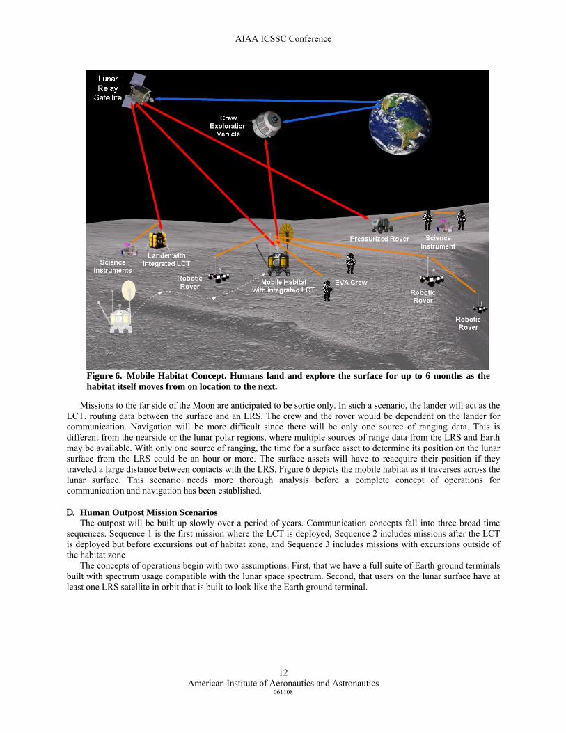
Missions to the far side of the Moon are anticipated to be sortie only. In such a scenario, the lander will act as the
LCT, routing data between the surface and an LRS. The crew and the rover would be dependent on the lander for communication. Navigation will be more difficult since there will be only one source of ranging data. This is different from the nearside or the lunar polar regions, where multiple sources of range data from the LRS and Earth may be available. With only one source of ranging, the time for a surface asset to determine its position on the lunar surface from the LRS could be an hour or more. The surface assets will have to reacquire their position if they traveled a large distance between contacts with the LRS. Figure 6 depicts the mobile habitat as it traverses across the lunar surface. This scenario needs more thorough analysis before a complete concept of operations for communication and navigation has been established.
D. Human Outpost Mission Scenarios The outpost will be built up slowly over a period of years. Communication concepts fall into three broad time
sequences. Sequence 1 is the first mission where the LCT is deployed, Sequence 2 includes missions after the LCT is deployed but before excursions out of habitat zone, and Sequence 3 includes missions with excursions outside of the habitat zone
The concepts of operations begin with two assumptions. First, that we have a full suite of Earth ground terminals built with spectrum usage compatible with the lunar space spectrum. Second, that users on the lunar surface have at least one LRS satellite in orbit that is built to look like the Earth ground terminal.
Figure 6. Mobile Habitat Concept. Humans land and explore the surface for up to 6 months as the habitat itself moves from on location to the next.
AIAA ICSSC Conference
American Institute of Aeronautics and Astronautics
061108
13
1. A1. Sequence 1
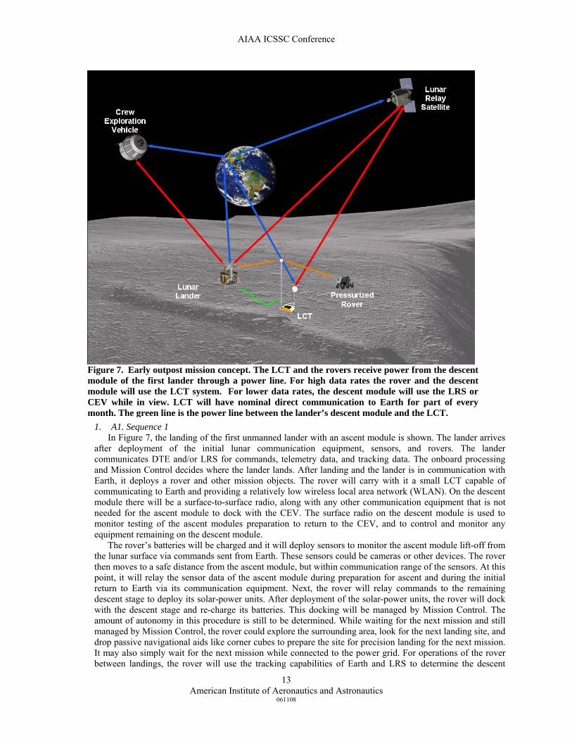
In Figure 7, the landing of the first unmanned lander with an ascent module is shown. The lander arrives after deployment of the initial lunar communication equipment, sensors, and rovers. The lander communicates DTE and/or LRS for commands, telemetry data, and tracking data. The onboard processing and Mission Control decides where the lander lands. After landing and the lander is in communication with Earth, it deploys a rover and other mission objects. The rover will carry with it a small LCT capable of communicating to Earth and providing a relatively low wireless local area network (WLAN). On the descent module there will be a surface-to-surface radio, along with any other communication equipment that is not needed for the ascent module to dock with the CEV. The surface radio on the descent module is used to monitor testing of the ascent modules preparation to return to the CEV, and to control and monitor any equipment remaining on the descent module.
The rover’s batteries will be charged and it will deploy sensors to monitor the ascent module lift-off from the lunar surface via commands sent from Earth. These sensors could be cameras or other devices. The rover then moves to a safe distance from the ascent module, but within communication range of the sensors. At this point, it will relay the sensor data of the ascent module during preparation for ascent and during the initial return to Earth via its communication equipment. Next, the rover will relay commands to the remaining descent stage to deploy its solar-power units. After deployment of the solar-power units, the rover will dock with the descent stage and re-charge its batteries. This docking will be managed by Mission Control. The amount of autonomy in this procedure is still to be determined. While waiting for the next mission and still managed by Mission Control, the rover could explore the surrounding area, look for the next landing site, and drop passive navigational aids like corner cubes to prepare the site for precision landing for the next mission. It may also simply wait for the next mission while connected to the power grid. For operations of the rover between landings, the rover will use the tracking capabilities of Earth and LRS to determine the descent
Figure 7. Early outpost mission concept. The LCT and the rovers receive power from the descent module of the first lander through a power line. For high data rates the rover and the descent module will use the LCT system. For lower data rates, the descent module will use the LRS or CEV while in view. LCT will have nominal direct communication to Earth for part of every month. The green line is the power line between the lander’s descent module and the LCT.
AIAA ICSSC Conference
American Institute of Aeronautics and Astronautics
061108
14
module coordinates and its own coordinates as it moves away from the descent module. The latter function may be useful for it to determine the coordinates of various distinguishable terrain features prior to the next mission. The rover will use the frequency bands listed in Table 3. Ka-band at 26 GHz will be used to transmit the high data rate DTE or LRS. The frequency to the LCT will be at 23 GHz. The TDRSS S-band channel will be used for navigation and for command, control and telemetry. However, if navigation is not desired then point-to-point communication DTE or to LRS up to 3 Mbps coded is possible at S-band. The frequency for the WLAN has not been determined, but for the trade studies two frequencies were used for analysis. They were 2.4 GHz and 3.8 GHz. If the chosen WLAN radio frequency is near the TDRSS bands (2.2 GHz transmitting and 2.0 receiving) then it may be possible to combine the two radios into one software-defined radio using the same antenna system. However, during the trade studies there were no assumptions on the use of or the non-use of software-defined radios.
2. A2. Sequence 2
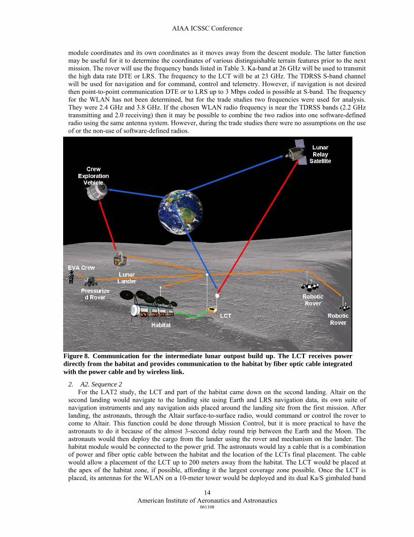
For the LAT2 study, the LCT and part of the habitat came down on the second landing. Altair on the second landing would navigate to the landing site using Earth and LRS navigation data, its own suite of navigation instruments and any navigation aids placed around the landing site from the first mission. After landing, the astronauts, through the Altair surface-to-surface radio, would command or control the rover to come to Altair. This function could be done through Mission Control, but it is more practical to have the astronauts to do it because of the almost 3-second delay round trip between the Earth and the Moon. The astronauts would then deploy the cargo from the lander using the rover and mechanism on the lander. The habitat module would be connected to the power grid. The astronauts would lay a cable that is a combination of power and fiber optic cable between the habitat and the location of the LCTs final placement. The cable would allow a placement of the LCT up to 200 meters away from the habitat. The LCT would be placed at the apex of the habitat zone, if possible, affording it the largest coverage zone possible. Once the LCT is placed, its antennas for the WLAN on a 10-meter tower would be deployed and its dual Ka/S gimbaled band
Figure 8. Communication for the intermediate lunar outpost build up. The LCT receives power directly from the habitat and provides communication to the habitat by fiber optic cable integrated with the power cable and by wireless link.
AIAA ICSSC Conference
American Institute of Aeronautics and Astronautics
061108
15
antenna would be deployed. The WLAN antennas would be sector antennas providing 360-degree coverage of the habitat zone. The gimbaled Ka/S band antenna would begin to track either the LRS or Earth. When the Earth is above the lunar horizon the Ka/S band antenna would track LRS when LRS is in view; otherwise it would track Earth.
After the LCT is deployed and examined by the crew, the rovers, the habitat module, the lander, anything connected to the power grid, and any other mobile asset will communicate primarily through the LCT as seen Fig. 7. At this time the LCT routes the data among all the surface users and between the surface users and Earth. If the crew moves out of site of the LCT, they can use the rover surface radio system to communicate with the LCT, or use the rover’s small gateway to relay the signal to LRS or Earth. From there the signals could be relayed to the appropriate locations on Earth or the Moon.
The LCT and the LRS, both with identical atomic clocks, will provide the local time for the lunar environment. This time is necessary for the surface wireless communication system and for the surface navigation system. While the crew is on the surface the LCT will acquire its position from navigation data from Earth and LRS. When the ascent module with the crew finally lifts off, the LCT along with LRS and Earth, can provide navigation data to the ascent module for a more accurate approach to CEV.
3. A3. Sequence 3
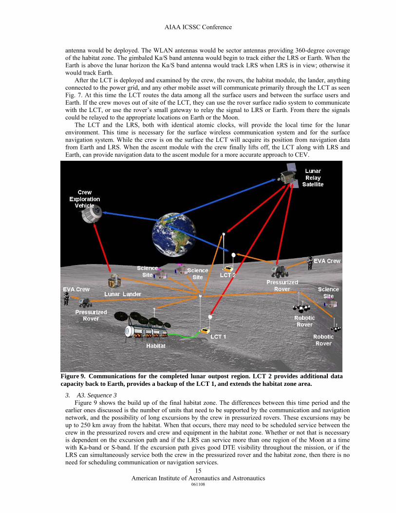
Figure 9 shows the build up of the final habitat zone. The differences between this time period and the earlier ones discussed is the number of units that need to be supported by the communication and navigation network, and the possibility of long excursions by the crew in pressurized rovers. These excursions may be up to 250 km away from the habitat. When that occurs, there may need to be scheduled service between the crew in the pressurized rovers and crew and equipment in the habitat zone. Whether or not that is necessary is dependent on the excursion path and if the LRS can service more than one region of the Moon at a time with Ka-band or S-band. If the excursion path gives good DTE visibility throughout the mission, or if the LRS can simultaneously service both the crew in the pressurized rover and the habitat zone, then there is no need for scheduling communication or navigation services.
Figure 9. Communications for the completed lunar outpost region. LCT 2 provides additional data capacity back to Earth, provides a backup of the LCT 1, and extends the habitat zone area.

AIAA ICSSC Conference
American Institute of Aeronautics and Astronautics
061108
16
At the end of the build up phase of the habitat zone there will be two LCTs. The location of the second LCT has not been determined, but it serves as the backup to the first one. Fortuitous placement of the second LCT could allow expansion of the habitat zone coverage area.
Within all the scenarios for development of the habitat zone, there is the requirement that all the radios on the LCTs, the rovers and suits are field replaceable. The component boxes on the radios on the LCTs, the lander and the rovers should be the same or cross compatible. The ability to re-use the radios will lessen the cost of the communication system while providing an increase redundancy within the system without additional cost.
IV. LCT Definition, Types and Design Drivers
A. Definition For the purposes of this paper, the Lunar Communications Terminal is defined in a broad sense as an element of
the surface segment of the overall lunar architecture, and is comprised of the following essential components: the surface wireless or wired component, the access component to lunar orbiting entities, and the direct-to-Earth component.
The essential function of the LCT is to multiplex and route data traffic from lunar surface elements either to lunar orbiting entities or to the Earth over high data rate broadband signals4. Similarly, data traffic from lunar orbiting entities or the Earth is de-multiplexed and distributed to applicable lunar surface elements. The architecture of the essential components of the LCT is shown in Figure 10.
B. Types Based on discussions in Sections II and III, Table 4 illustrates the four identified mission scenarios and tabulates
the associated LCT requirements in terms of data rates, surface range, and number of required interfaces. From this information, three LCT types were conceptualized to satisfy these requirements. The three LCT types are defined in terms of capacity: small, medium, or large. The three LCT types are further described in Section V of this paper.
Outpost Mission scenarios require an LCT with the largest capacity in terms of number of interfaces, storage capacity and data rates. The outpost LCT must support the largest number of surface elements including pressurized rovers, robotic rovers, ISRUs, and EVA crewmembers. The outpost LCT also provides communication capabilities for the habitat over either fiber optic or surface wireless links. Science and robotic missions will require the smallest capacity in terms of data rates, storage capacity and surface elements served since the majority of science instruments do not require high data rates. Sortie missions may require high-definition video, which will require higher capacity in terms of data rate and storage capability than the science and robotic missions. Since EVA crewmembers are limited to 1 km excursions from the pressurized rover, sortie missions will require a relatively low surface range of 1 km around the pressurized rover. Human mobile exploration missions will require the greatest
LCT
SurfaceWireless or
WiredComponent
SurfaceWireless or
WiredComponent
AccessComponentAccess
ComponentDirect-to-
Earth Component
Direct-to-Earth
Component
SurfaceElement
OrbitingEntity Earth
SurfaceElement
LCT
SurfaceWireless or
WiredComponent
SurfaceWireless or
WiredComponent
AccessComponentAccess
ComponentDirect-to-
Earth Component
Direct-to-Earth
Component
SurfaceElement
OrbitingEntity Earth
SurfaceElement
Figure 10. Architecture of the essential components of the LCT.

AIAA ICSSC Conference
American Institute of Aeronautics and Astronautics
061108
17
surface range in order to maintain contact with the outpost or lunar lander. Data rates and storage capacities are on the same order as the sortie missions, and therefore will require a medium capacity LCT.
C. Design Drivers The primary design driver for the LCTs was the minimization of the communication burden on the lunar surface
elements. This was accomplished through the provision of a high data rate and low power communication option to an LRS or to Earth directly. This approach resulted in a reduction of the radios’ power, size and mass. To accomplish these goals the LCT must provide coverage over the appropriate area. The main LCT must cover the habitat zone, which includes the habitat and the landing zone. This is necessary for the crew to call or tele-robotically maneuver a rover to the lander in a timely manner and to maneuver the rover back to the power system between missions. This requirement resulted in a coverage radius of about 6 km at the lunar south pole. That range is provided by a 10-meter tower on the LCT for surface-to-surface communication. In addition, the LCT must provide the capability to route all data between Earth and the users. The maximum number of users within the habitat zone was estimated to be 15. Because of the aggregate data rate at the habitat zone, the router within the LCT needed the capability to process 300 Mbps. The mass storage requirements were designed to store up to 4 hours of data generation on the lunar surface for all elements excluding the habitat. This resulted in a data storage requirement of 300 GB.
An 802.16e network was chosen for the link analysis, because that commercial standard is capable of providing the interoperability, security, and quality of service. Although, the standard currently does not meet NASA’s need of a mesh network capability for the EVA suits.
Navigation was included in the main LCT design to enable precision landing around the habitat zone. This facilitated the need to include an atomic clock in the LCT design. Once included, the LCT and LRS can establish a local Moon time reference.
Wherever possible in the design of the LCT, common subsystems that exist or which are currently under development for other lunar systems, were used to minimize the cost of development and the cost of additional units. This includes the radios, the communication and the navigation subsystems on the LRS, the lander, and the CEV. The gateway radios on the LCT are the compliment radios on the LRS. For example, the LCT transmits at 26 GHz and receives at 23 GHz while the LRS transmits at 23 GHz and receives at 26 GHz. The survivability of the LCT in the lunar environment is left for future work.
Table 4. Requirements according to Mission Class.
Surface Link Access Link Long Haul
Science and Robotic (1) 1 to 5 0-20 < 200 kbps < 4mbps 200 kbps 90MB
Sortie (2) <= 2 0-10 < 2 X 10Mbps 2-60Mbps <20Mbps < 9GB
Human Exploration (3) 5 to 10 0-250 < 20 Mbps < 30 Mbps < 20 Mbps 4.5GB per
roverLarge, High-Capacity, Base Camp, Outpost LCT (4)
15 0-40 80 100 X 2 100 X 2 0.3 TB
(4) Long-term human survivability
(1) Science, monitoring, environment measurements, terrain (2) Human survivability, science(3) Survivability, science, locale, exploration, RFIDs
Storage Capacity Mission Class # of interfaces
Link Capacity (Mbps)Surface Range (km)
AIAA ICSSC Conference
American Institute of Aeronautics and Astronautics
061108
18
V. Lunar Communications Terminals: Architectural Design This section describes the LCT element of the lunar surface segment of the overall architecture. Specifically, the
architecture of the small, medium, and large capacity LCT is described as well as the architecture of the LCT within the context of the overall architecture. The overall lunar architecture includes other elements such as the habitat, LRS, and pressurized rovers. The architecture for the lunar communications and navigation aspects of the Constellation mission are further described in ref. 2.
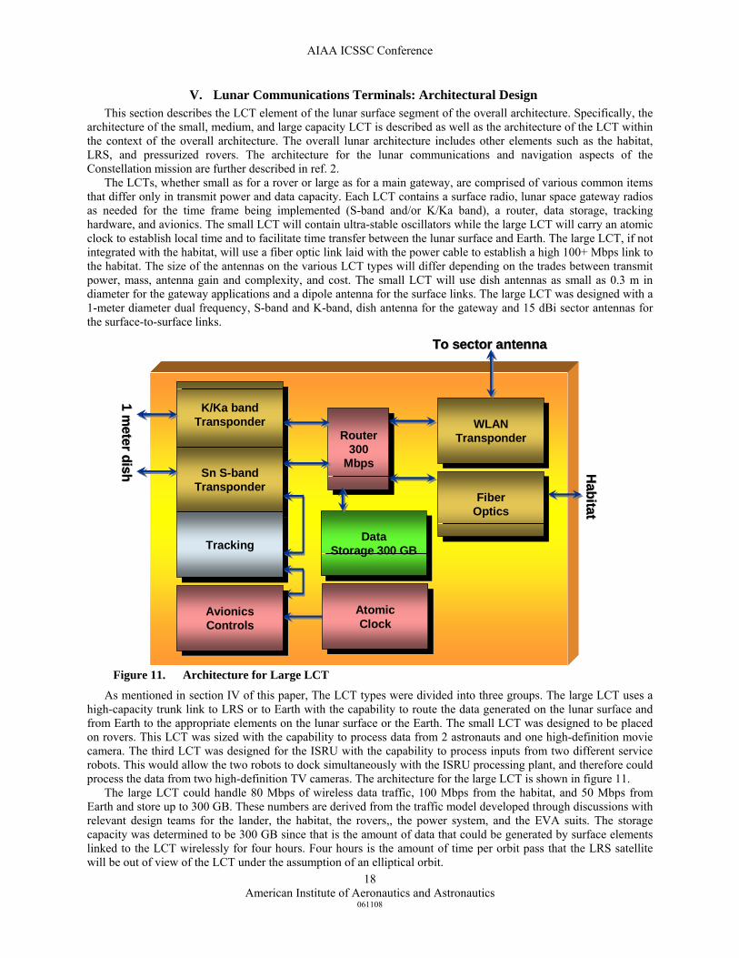
The LCTs, whether small as for a rover or large as for a main gateway, are comprised of various common items that differ only in transmit power and data capacity. Each LCT contains a surface radio, lunar space gateway radios as needed for the time frame being implemented (S-band and/or K/Ka band), a router, data storage, tracking hardware, and avionics. The small LCT will contain ultra-stable oscillators while the large LCT will carry an atomic clock to establish local time and to facilitate time transfer between the lunar surface and Earth. The large LCT, if not integrated with the habitat, will use a fiber optic link laid with the power cable to establish a high 100+ Mbps link to the habitat. The size of the antennas on the various LCT types will differ depending on the trades between transmit power, mass, antenna gain and complexity, and cost. The small LCT will use dish antennas as small as 0.3 m in diameter for the gateway applications and a dipole antenna for the surface links. The large LCT was designed with a 1-meter diameter dual frequency, S-band and K-band, dish antenna for the gateway and 15 dBi sector antennas for the surface-to-surface links.
As mentioned in section IV of this paper, The LCT types were divided into three groups. The large LCT uses a
high-capacity trunk link to LRS or to Earth with the capability to route the data generated on the lunar surface and from Earth to the appropriate elements on the lunar surface or the Earth. The small LCT was designed to be placed on rovers. This LCT was sized with the capability to process data from 2 astronauts and one high-definition movie camera. The third LCT was designed for the ISRU with the capability to process inputs from two different service robots. This would allow the two robots to dock simultaneously with the ISRU processing plant, and therefore could process the data from two high-definition TV cameras. The architecture for the large LCT is shown in figure 11.
The large LCT could handle 80 Mbps of wireless data traffic, 100 Mbps from the habitat, and 50 Mbps from Earth and store up to 300 GB. These numbers are derived from the traffic model developed through discussions with relevant design teams for the lander, the habitat, the rovers,, the power system, and the EVA suits. The storage capacity was determined to be 300 GB since that is the amount of data that could be generated by surface elements linked to the LCT wirelessly for four hours. Four hours is the amount of time per orbit pass that the LRS satellite will be out of view of the LCT under the assumption of an elliptical orbit.
1 meter dish
1 meter dish
K/Ka band TransponderK/Ka band
Transponder
Sn S-band TransponderSn S-band
Transponder
Tracking Tracking
Router 300
Mbps
Router 300
Mbps
WLANTransponder
WLANTransponder
Fiber Optics Fiber
Optics
Avionics Controls
Avionics Controls
Data Storage 300 GB
Data Storage 300 GB
To sector antennaTo sector antenna
Habitat
Habitat
Atomic Clock
Atomic Clock
1 meter dish
1 meter dish
K/Ka band TransponderK/Ka band
Transponder
Sn S-band TransponderSn S-band
Transponder
Tracking Tracking
Router 300
Mbps
Router 300
Mbps
WLANTransponder
WLANTransponder
Fiber Optics Fiber
Optics
Avionics Controls
Avionics Controls
Data Storage 300 GB
Data Storage 300 GB
To sector antennaTo sector antenna
Habitat
Habitat
Atomic Clock
Atomic Clock
Figure 11. Architecture for Large LCT

AIAA ICSSC Conference
American Institute of Aeronautics and Astronautics
061108
19
The medium and the small LCT types were designed to handle 22 Mbps and 11 Mbps, respectively. This is again
derived from the traffic needs of the rovers, the EVA suits, and the ISRU. The architecture for the small or medium LCT is shown in figure 12.
All LCT designs used gimbaled antennas for the S-band and Ka-band link from the lunar surface. The large and possibly the medium LCT types use sector antennas with a gain of 15 dBi and a 10-meter antenna boom for the wireless surface communication, while the small LCT and possibly the medium LCT employed dipole antennas for the wireless communication. The choice between sector antenna and the dipole antenna on the medium LCT is mission specific, but most likely the sector antenna will be deployed on non-mobile elements like the ISRU, while the dipole antennas will be deployed on mobile systems.
.
A. Science and Robotic Mission Scenarios The architecture for Science and Robotic mission scenarios is depicted in figure 13 where the Robotic rover
incorporates the small LCT for multiplexing and de-multiplexing of data from various surface elements including high-resolution cameras, science instruments, and ISRUs. The LCT on the robotic rover may communicate to LRS or directly to Earth via Ka-Band or S-Band. The surface elements transmit and receive data using a wireless protocol such as 802.16e or optionally low-frequency links for surface elements with low data rate requirements.
dipole antenna dipole antenna
K/Ka band TransponderK/Ka band
Transponder
Sn S-band TransponderSn S-band
Transponder
Tracking Tracking
Router 12 or 25
Mbps
Router 12 or 25
Mbps
WLANTransponder
WLANTransponder
Avionics Controls
Avionics Controls
Data Storage 15 GB
Data Storage 15 GB
0.3 meter dish
0.3 meter dish
USO USO
Figure 12. Architecture for small or Medium LCT.

AIAA ICSSC Conference
American Institute of Aeronautics and Astronautics
061108
20
B. Early Human (Sortie) Mission Scenarios The architecture for sortie mission scenarios is depicted in figure 14 where the pressurized rover incorporates a
medium LCT for the multiplexing and de-multiplexing of data to and from surface elements. During excursions from the landing or habitat zone, crewmembers traveling in pressurized rovers may communicate either directly to Earth or through the LRS. Crewmembers performing EVA will communicate with each other and to the pressurized rovers using the surface wireless protocol. In figure 14, duplicate possible lunar elements, such as the second pressurized rover, are not shown for clarity purposes.
Figure 13. Lunar Architecture for Robotic and Science Mission Scenarios.

AIAA ICSSC Conference
American Institute of Aeronautics and Astronautics
061108
21
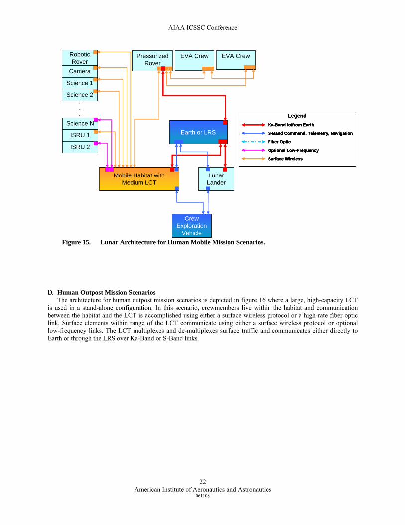
C. Exploration Mission Scenarios The architecture for human mobile exploration scenarios is depicted in figure 15 where the mobile habitat uses
the Medium LCT for the multiplexing and de-multiplexing of surface traffic and for communication directly to Earth or through the LRS. Surface elements communicate with the mobile habitat using either a surface wireless protocol or optional low-frequency links for surface elements with low data rate requirements. The mobile habitat communicates with the CEV over S-Band while in view.
Lunar Landerw/ Medium LCT
Earth or LRS
EVACrew
EVACrew
RoboticRover
Camera
Science
PressurizedRover
Crew Exploration
Vehicle
Ka-Band to/from Earth
S-Band Command, Telemetry, Navigation
Fiber Optic
Optional Low-Frequency
Surface Wireless
Legend
Lunar Landerw/ Medium LCT
Earth or LRS
EVACrew
EVACrew
RoboticRover
Camera
Science
PressurizedRover
Crew Exploration
Vehicle
Ka-Band to/from Earth
S-Band Command, Telemetry, Navigation
Fiber Optic
Optional Low-Frequency
Surface Wireless
LegendKa-Band to/from Earth
S-Band Command, Telemetry, Navigation
Fiber Optic
Optional Low-Frequency
Surface Wireless
Ka-Band to/from Earth
S-Band Command, Telemetry, Navigation
Fiber Optic
Optional Low-Frequency
Surface Wireless
Legend
Figure 14. Lunar Architecture for Sortie Mission Scenarios.
AIAA ICSSC Conference
American Institute of Aeronautics and Astronautics
061108
22
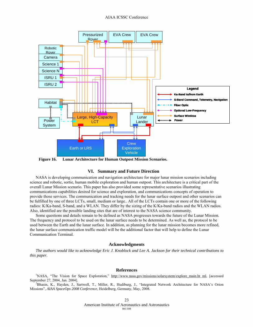
D. Human Outpost Mission Scenarios The architecture for human outpost mission scenarios is depicted in figure 16 where a large, high-capacity LCT
is used in a stand-alone configuration. In this scenario, crewmembers live within the habitat and communication between the habitat and the LCT is accomplished using either a surface wireless protocol or a high-rate fiber optic link. Surface elements within range of the LCT communicate using either a surface wireless protocol or optional low-frequency links. The LCT multiplexes and de-multiplexes surface traffic and communicates either directly to Earth or through the LRS over Ka-Band or S-Band links.
Lunar Lander
Earth or LRS
Mobile Habitat withMedium LCT
Pressurized Rover
EVA Crew EVA CrewRoboticRover
Camera
Science 1
Science N
ISRU 1
ISRU 2
Crew Exploration
Vehicle
Science 2...
Ka-Band to/from Earth
S-Band Command, Telemetry, Navigation
Fiber Optic
Optional Low-Frequency
Surface Wireless
Legend
Lunar Lander
Earth or LRS
Mobile Habitat withMedium LCT
Pressurized Rover
EVA Crew EVA CrewRoboticRover
Camera
Science 1
Science N
ISRU 1
ISRU 2
Crew Exploration
Vehicle
Science 2...
Ka-Band to/from Earth
S-Band Command, Telemetry, Navigation
Fiber Optic
Optional Low-Frequency
Surface Wireless
LegendKa-Band to/from Earth
S-Band Command, Telemetry, Navigation
Fiber Optic
Optional Low-Frequency
Surface Wireless
Ka-Band to/from Earth
S-Band Command, Telemetry, Navigation
Fiber Optic
Optional Low-Frequency
Surface Wireless
Legend
Figure 15. Lunar Architecture for Human Mobile Mission Scenarios.
AIAA ICSSC Conference
American Institute of Aeronautics and Astronautics
061108
23
VI. Summary and Future Direction NASA is developing communication and navigation architecture for major lunar mission scenarios including
science and robotic, sortie, human mobile exploration and human outpost. This architecture is a critical part of the overall Lunar Mission scenario. This paper has also provided some representative scenarios illustrating communications capabilities desired for science and exploration, and communications concepts of operation to provide those services. The communication and tracking needs for the lunar surface outpost and other scenarios can be fulfilled by one of three LCTs, small, medium or large.. All of the LCTs contain one or more of the following radios: K/Ka-band, S-band, and a WLAN. They differ by the sizing of the K/Ka-band radios and the WLAN radios. Also, identified are the possible landing sites that are of interest to the NASA science community.
Some questions and details remain to be defined as NASA progresses towards the future of the Lunar Mission. The frequency and protocol to be used on the lunar surface needs to be determined. As well as, the protocol to be used between the Earth and the lunar surface. In addition, as planning for the lunar mission becomes more refined, the lunar surface communication traffic model will be the additional factor that will help to define the Lunar Communication Terminal.
Acknowledgments The authors would like to acknowledge Eric J. Knoblock and Lee A. Jackson for their technical contributions to
this paper.
References 1NASA, “The Vision for Space Exploration,” http://www.nasa.gov/missions/solarsystem/explore_main.ht ml, [accessed
September 27, 2004, Jan. 2004]. 2Bhasin, K., Hayden, J., Sartwell, T., Miller, R., Hudiburg, J., “Integrated Network Architecture for NASA’s Orion
Missions”, AIAA SpaceOps 2008 Conference, Heidelberg, Germany, May, 2008.
Earth or LRS
Large, High-CapacityLCT
Habitat
Power System
Pressurized Rover
EVA Crew EVA Crew
RoboticRover
Camera
Science 1
Science N
ISRU 1
ISRU 2
Lunar Lander
CrewExploration
Vehicle
LegendKa-Band to/from Earth
S-Band Command, Telemetry, Navigation
Fiber Optic
Optional Low-Frequency
Surface WirelessPower
LegendKa-Band to/from Earth
S-Band Command, Telemetry, Navigation
Fiber Optic
Optional Low-Frequency
Surface WirelessPower
Figure 16. Lunar Architecture for Human Outpost Mission Scenarios.
AIAA ICSSC Conference
American Institute of Aeronautics and Astronautics
061108
24
3Soloff, J., et al, “A Sustained Proximity Network for Multi-Mission Lunar Exploration,” AIAA 1st Space Exploration Conference, 2005.
4Flanegan, M., et al, “NASA’s Lunar Communication and Navigation Architecture”, AIAA SpaceOps 2008 Conference, Heidelberg, Germany, May, 2008.
5Cooke, D., Yoder, G., Coleman, S., Hensley, S. "Lunar Architecture Update", AIAA/NASA 3rd Space Exploration Conference, Denver, Colorado, 2008.
6Taylor, G., "Sampling Strategies for Lunar Sample Return Missions,” 39th Annual Lunar and Planetary Science Conference, Special Session: Lunar Science, Past, Present, and Future, League City, TX, 2008.
7Neal, C., "Future Lunar Science Opportunities - What's Left to be Done", 39th Annual Lunar and Planetary Science Conference, Special Session: Lunar Science, Past, Present, and Future, League City, TX, 2008.
8Kiefer, W., Huang, S., Neal, C., Wieczorek, M., "The Thermal Structure and Evolution of the Moon: Apollo Heat Flow Results, Unresolved Questions and Future Objectives", 39th Annual Lunar and Planetary Science Conference, Special Session: Lunar Science, Past, Present, and Future, League City, TX, 2008.
9New Views of the Moon, Reviews in Mineralogy and Geochemistry Vol. 60, Editors: Bradley L. Joliff, Mark A. Wieczorek, Charles K. Shearer, and Clive R. Neal, 2006.
103rd International Exploration Conference, "International Lunar Network", Alan Stern, NASA Science Mission Directorate, March 12, 2008.
11Stern, A., “International Lunar Network”, 39th Lunar and Planetary Science Conference, Lunar and Planetary Institute/NASA HQ (SMD), League City, TX, 2008.