robust exploration and commercial missions to the moon ...€¦ · robust exploration and...
TRANSCRIPT

1
Robust Exploration and Commercial Missions to the Moon Using
LANTR Propulsion and Lunar Liquid Oxygen Derived
from FeO-rich Pyroclastic Deposits
Stanley K. Borowski1, Stephen W. Ryan2, Laura M. Burke3, David R. McCurdy4 and James E. Fittje4
NASA Glenn Research Center, Cleveland, OH 44135
email: [email protected], telephone: (216) 977-7091
Claude R. Joyner
Aerojet Rocketdyne, West Palm Beach, FL 33410
The nuclear thermal rocket (NTR) has frequently been identified as a key space asset required
for the human exploration of Mars. This proven technology can also provide the affordable
“access through cislunar space” necessary for commercial development and sustained human
presence on the Moon. It is a demonstrated technology capable of generating both high thrust and
high specific impulse (Isp ~900 s) – twice that of today’s best chemical rockets. Nuclear lunar
transfer vehicles – consisting of a propulsion stage using three ~16.5 klbf “Small Nuclear Rocket
Engines (SNREs)”, an in-line propellant tank, plus the payload – can enable a variety of reusable
lunar missions. These include cargo delivery and crewed lunar landing missions. Even weeklong
“tourism” missions carrying passengers into lunar orbit for a day of sightseeing and picture
taking are possible. The NTR can play an important role in the next phase of lunar exploration
and development by providing a robust in-space lunar transportation system (LTS) that can allow
initial outposts to evolve into settlements supported by a variety of commercial activities such as
in-situ propellant production used to supply strategically located propellant depots and
transportation nodes. The use of lunar liquid oxygen (LLO2) derived from iron oxide (FeO)-rich
volcanic glass beads, found in numerous pyroclastic deposits on the Moon, can significantly
reduce the launch mass requirements from Earth by enabling reusable, surface-based lunar
landing vehicles (LLVs) using liquid oxygen/hydrogen (LO2/LH2) chemical rocket engines.
Afterwards, a LO2/LH2 propellant depot can be established in lunar equatorial orbit to supply the
LTS. At this point a modified version of the conventional NTR – called the LOX-augmented NTR,
or LANTR – is introduced into the LTS allowing bipropellant operation and leveraging the
mission benefits of refueling with lunar-derived propellants for Earth return. The bipropellant
LANTR engine utilizes the large divergent section of its nozzle as an “afterburner” into which
oxygen is injected and supersonically combusted with nuclear preheated hydrogen emerging from
the engine’s choked sonic throat—essentially “scramjet propulsion in reverse.” By varying the
oxygen-to-hydrogen mixture ratio, LANTR engines can operate over a range of thrust and Isp
values while the reactor core power level remains relatively constant. A LANTR-based LTS offers
unique mission capabilities including short transit time crewed cargo transports. Even a
“commuter” shuttle service may be possible allowing “one-way” trip times to and from the Moon
on the order of 36 hours or less. If only 1% of the extracted LLO2 propellant from identified
resource sites were available for use in lunar orbit, such a supply could support daily commuter
flights to the Moon for many thousands of years! The proposed paper outlines an evolutionary
architecture and examines a variety of mission types and transfer vehicle designs, along with the
increasing demands on LLO2 production as mission complexity and V requirements increase. A
comparison of vehicle features and engine operating characteristics, for both NTR and LANTR
engines, is also provided along with a discussion of the propellant production and mining
requirements associated with using FeO-rich volcanic glass as source material.
------------------------------------------------------ 1Chemical & Thermal Propulsion Systems Branch, 21000 Brookpark Road, MS: 86-8, AIAA Associate Fellow 2Aeronautics & Ground-Based Systems Branch, 21000 Brookpark Road, MS: 105-3, Cleveland, OH 44135 3Mission Architecture & Analysis Branch, 21000 Brookpark Road, MS: 162-2, Cleveland, OH 44135 4Vantage Partners, LLC at Glenn Research Center, 3000 Aerospace Parkway, Brook Park, OH 44142
https://ntrs.nasa.gov/search.jsp?R=20170009140 2020-06-22T09:49:51+00:00Z

2
Nomenclature
°C / °K = temperature (in degrees Celsius / Kelvin)
EEO = Elliptical Earth Orbit
ELH2 = Earth-supplied Liquid Hydrogen propellant
IMLEO = Initial Mass in Low Earth Orbit
klbf = thrust (1000’s of pounds force)
LEO = Low Earth Orbit (= 407 km circular / 28.5 deg inclination)
LLO = Low Lunar Orbit (= 300 km circular / equatorial)
LTV = Lunar Transfer Vehicle
LUNOX = Lunar-derived Liquid Oxygen; another name for LLO2
NERVA = Nuclear Engine for Rocket Vehicle Applications
NLTV = Nuclear-powered Lunar Transfer Vehicle
O/H MR = Oxygen-to-Hydrogen Mixture Ratio
SLS / HLV = Space Launch System / Heavy Lift Vehicle
t = metric ton (1 t = 1000 kg)
V = velocity change increment (km/s)
I. Introduction and Background
oday there is considerable discussion within NASA, the Congress and industry regarding the future direction
and focus of the United States’ human space program. According to NASA, the direction and focus is a
“Journey to Mars” [1] sometime around the mid-to-late 2030’s. However, while NASA’s sights are set on Mars,
there is another destination of interest to the worldwide space community – the Moon. Located just 3 days from
Earth, the Moon is an entire world awaiting exploration, future settlement and potential commercialization. It has
abundant resources and is an ideal location to test and demonstrate key technologies and systems (e.g., surface
habitation, long-range pressurized rovers, surface power and resource extraction systems) that will allow people to
explore, work, and live self-sufficiently on another planetary surface.
Despite NASA’s past “been there, done that” attitude towards the Moon, a human lunar return mission has strong
appeal to many others who would like to see humans again walk on its surface. With the upcoming 50th
anniversaries of the Apollo 8 orbital mission of the Moon (on December 24-25, 1968) and the Apollo 11 landing
mission (on July 20-21, 1969) fast approaching, lunar missions are again a topic of considerable discussion both
within NASA [2] and outside. Plans for human surface missions and even settlements on the Moon in the 2025 –
2030 timeframe are being openly discussed by Europe, China, and Russia [3,4,5]. A number of private companies in
the United States – SpaceX [6], Bigelow Aerospace (BA) [7], Shackleton Energy Company (SEC) [8], United
Launch Alliance (ULA) [9], and Blue Origin [10] – are also discussing commercial ventures to the Moon, along
with possible public-private partnerships with NASA.
This past February, Space X announced [6] that it would send two tourists on a week-long, "free return" flyby
mission around the Moon in 2018 – undoubtedly to capitalize on the significance of NASA's historic Apollo 8
mission. In early March, Bigelow Aerospace discussed its plans [7] to launch a private space station into LEO by
2020 using ULA’s Atlas V launch vehicle. The station would use the BA-330 habitat module – the numerical
designation referring to the 330 m3 of internal volume that the BA-330 possesses once inflated. The company went
on to say that a variant of the BA-330 module could also be placed in low lunar orbit to serve as a transportation
node / refueling depot for astronauts and spacecraft making their way to and from the Moon and the lunar surface.
Lunar-derived propellant (LDP) production – specifically LLO2 and LLH2 – has been identified as a key
technology offering significant mission leverage [11] and it figures prominently in both SEC’s and ULA’s plans
[8,9] for commercial lunar development. Samples returned from different sites on the Moon during the Apollo
missions have shown that the lunar regolith has a significant oxygen content. The FeO-rich volcanic glass beads
returned on the final Apollo (17) mission have turned out to be a particularly attractive source material for oxygen
extraction based on hydrogen reduction experiments conducted by Allen et al. [12]. Post-Apollo lunar probe
missions have also provided orbital data indicating the possible existence of large quantities of water ice trapped in
deep, permanently shadowed, craters located at the Moon’s poles [13]. This data has generated considerable
excitement and speculation, including plans for a commercial venture by SEC [8] that proposes to mine lunar polar
ice (LPI), convert it to rocket propellant, and then sell it at propellant depots located in LEO.
T

3
Besides providing an ideal location for testing surface systems and “in-situ” resource utilization (ISRU)
equipment, lunar missions also provide a unique proving ground to demonstrate an important in-space technology –
Nuclear Thermal Propulsion (NTP). With its high thrust and high specific impulse (Isp ~ 900 s) – twice that of
today’s best chemical rockets – the NTR can play an important role in “returning humans to the Moon to stay” by
enabling a reusable in-space LTS that provides the affordable access through cislunar space necessary for initial
lunar outposts to evolve into thriving settlements engaged in a variety of commercial activities.
Over the past three decades, engineers at Glenn Research Center (GRC) have analyzed NTP’s use for lunar
missions, quantified its benefits and developed vehicle concept designs for a variety of exploration and commercial
mission applications [14,15,16,17]. A sampling of these vehicle concepts and mission applications is shown in
Fig. 1. Also shown is a transition away from vehicles using a single high thrust engine (Fig. 1a) to vehicles using
clustered lower thrust engines (Figs.1b–1e) to help reduce development costs and increase mission safety and
reliability by providing an “engine out” capability.
The NTR achieves its high specific impulse by using LH2 to maintain the reactor fuel elements at their required
operating temperature then exhausting the heated hydrogen gas exiting the reactor out the engine’s nozzle to
generate thrust. Because the NTR is a monopropellant engine, a key question emerges “How can the high
performance of the NTR and the leverage potential of LDP best be exploited?” The answer is the “LO2-Augmented”
NTR (or LANTR) – a LH2-cooled NTR outfitted with an O2 “afterburner nozzle” and feed system [18,19,20].
Combining NTR and supersonic combustion ramjet engine technologies, LANTR is a versatile, high performance
engine that can enable a robust nuclear LTS with unique capabilities and can take full advantage of the mission
leverage provided by using LDPs by allowing “bipropellant” operation.
Figure 1. Sampling of Past and Recent Crewed, Cargo and Commercial Lunar Transfer Vehicles
Designed by GRC Shows a Transition Away from Single Large to Multiple Smaller Engines

4
In light of the current interest being expressed in LDPs [8,9], GRC engineers have been re-examining the impact
of infusing LANTR propulsion into a nuclear-powered LTS that utilizes LDPs. The author (Borowski) presented a
paper on this topic 20 years ago at the 33rd Joint Propulsion Conference in Seattle, Washington [18]. In that work,
the primary LDP and feedstock material considered was LLO2, also referred to as LUNOX, and FeO-rich volcanic
glass beads, and only ELH2 was used in the LANTR LTS. The decision to use LUNOX back then was based on an
extensive set of hydrogen reduction experiments [21,22] that established “ground truth” for oxygen release from
samples of lunar soil and volcanic glass beads returned by the Apollo missions. The highest yields – in the range of
4-5 weight percent (wt%) – were obtained from the iron-rich volcanic glass samples [21,22] collected during the
Apollo 17 mission to Taurus-Littrow (Fig 2). Another important consideration was the identification of a significant
number of large pyroclastic “dark mantle deposits” (DMDs) containing this glassy material on the lunar nearside
just north of the “equatorial corridor” [23,24].
Figure 2. Astronaut Harrison Schmitt Collects Samples of DM Material at Shorty Crater – Apollo 17 Mission
This same degree of certainty cannot be claimed for LPI. While considerable enthusiasm has been expressed
about mining and processing LPI for rocket propellant, and using it to create a space-faring cislunar economy [25],
the ground truth about LPI must first be established before this enthusiasm is warranted. Robotic surface missions
will be required to quantify the physical state of the water ice, its vertical thickness and areal extent, and the levels
of soil contamination. Also, the permanently shadowed craters, where LPI is thought to exist, are deep (~4.2 km for
Shackleton Crater near the lunar south pole), and extremely cold (ranging from ~25 to 100 °K) posing major
challenges for mining and processing any cold, ice-bearing regolith that might be uncovered [26]. These conditions
may negate the apparent advantage that LPI has over volcanic glass as a feedstock material – namely, the ability to
provide a source of LLH2 as well as LLO2.
There are many scientifically interesting sites on the Moon that are far from the lunar poles. For example, the
Aristarchus Plateau (~27°N, 52°W) is located in the midst of a large expanse of DMD that can supply the feedstock
material needed to produce LUNOX. Access to this nearside, near-equatorial site should also be relatively easy. If a
decision were made to locate a research station or base there, producing oxygen locally would probably make more
sense rather than incurring the added complexity and cost of transporting it from the poles. Finally, oxygen
extraction from iron-rich mare soil or volcanic glass has an additional benefit – it also produces useful metals (iron
and titanium) which using LPI feedstock does not.
In view of these facts, this paper again focuses on LUNOX and volcanic glass as the primary LDP and feedstock
material. The potential mission benefits and issues associated with using LPI will be examined in a follow-on paper.
This paper provides a summary of our ongoing analysis results to date and touches on the following topics. First, the
oxygen extraction process and yields from candidate feedstock materials, system mass and power requirements,
siting and features of a commercial LUNOX production plant are discussed. Next, a system description of the NTR
and the LANTR concept are presented along with performance projections for the engine as a function of the
oxygen-to-hydrogen mixture ratio used in the afterburner nozzle. The mission and transportation system ground
rules and assumptions used in our analysis are then provided and used in an evolutionary mission architecture that
illustrates the benefits of using LANTR and LUNOX technologies quantifying them in terms of reduced vehicle
size, launch mass and required engine burn times. The potential for a robust, reusable LTS that includes short transit

5
time crewed cargo transports and commuter shuttles is discussed next along with the refueling needs, LUNOX
production rates and mining requirements needed to support these more demanding and higher V missions. The
paper ends with some concluding remarks and thoughts on the possibilities for future human expansion into the
Solar System using LANTR propulsion and sources of locally produced extraterrestrial propellant.
II. LUNOX: Its Benefits, Extraction Efficiency, Plant Characteristics and Siting Locations
Previous studies conducted by NASA and its contractors [27,28] have indicated a substantial benefit from using
lunar-derived propellants – specifically LLO2 in the lunar space transportation system. In a LTS using LO2/LH2
chemical rockets, ~6 kilograms (kg) of mass in LEO is required to place 1 kg of payload on the lunar surface (LS).
Of this 6 kg, ~70% (4.2 kg) is propellant and ~85.7% of this mass (3.6 kg) is oxygen assuming the engines operate
with an O/H MR of 6:1. Since the cost of placing a kilogram of mass on the LS is ~6 times the cost of delivering it
to LEO [11], the ability to produce LUNOX from processed lunar material can provide a significant mission benefit.
By providing a local source of oxygen for use in life support systems, fuel cells and the chemical rocket engines
used on LLVs, the IMLEO, launch costs and LTS size and complexity can all be reduced. Greater quantities of
“higher value” cargo (e.g., people, propellant processing equipment and scientific instruments) can also be
transported to LEO and on to the Moon instead of bulk propellant mass further reducing LTS costs.
LUNOX has also been mentioned as a potential commercial product because of its abundance. From the analysis
of samples brought back on the Apollo missions, nearly half the mass (~43%) of the Moon’s surface material is
oxygen [11] and at least 20 different techniques [29,30] have been identified for its extraction. The reduction of iron
oxide in the mineral “ilmenite” (FeTiO3) or in volcanic glass using hydrogen gas is among the simplest and best
studied. The technique involves a two-step process in which the FeO is first reduced to metal liberating oxygen and
forming water as shown below:
FeTiO3 + H2 ---> Fe + TiO2 + H2O or FeO (glass) + H2 ---> Fe + H2O
The water in then electrolyzed to produce oxygen and the hydrogen is recycled back to the processing plant to react
with more feedstock material [29,30]. In the hydrogen reduction experiments conducted by Allen et al. [21,22],
oxygen release was measured from samples of lunar soil and volcanic glass beads returned by the Apollo missions.
The results indicated that oxygen can be produced from a wide range of lunar soils and is strongly correlated with
the Fe2+ / FeO abundance in the soil as shown in Fig. 3. Iron-rich highland soils produced the smallest amount of
oxygen, ~1 to 2 wt%, while iron-rich mare soil samples produced ~3.6 wt%. The highest yields – in the range of 4 to
5 wt% – were obtained from the pyroclastic (volcanic) glass collected at the Apollo 17 Taurus-Littrow landing site.
The glass is extremely iron-rich with a Fe2+ content of ~17.8 wt%. The orange and black beads shown in Fig. 3 have
identical elemental compositions, but the black beads are largely crystalline while the orange beads are largely glass.
Figure 3. Volcanic Glass Beads and Oxygen Yields from Full Range of Apollo Samples [22]
6
Reduction of the orange glass beads produced an oxygen yield of ~4.3 wt% while the black crystalline beads
produced ~4.7 wt%, the highest for any of the samples [22]. Assuming the hydrogen reduction process, volcanic
glass feedstock, and a conservative oxygen yield of 4 wt%, a metric ton of LUNOX could be produced by
processing ~25 t of volcanic glass – a significant improvement over previous estimates.
As mentioned above, one of the most studied concepts for oxygen extraction utilizes hydrogen reduction of the
mineral ilmenite that is found in the lunar soil or mare basalts (lunar rock). LUNOX production scenarios that use
ilmenite exclusively will require processing to separate out the mineral and minimize the amount of material that
must be heated in order to release the oxygen. Processing of soil requires sizing and magnetic separation. If an
ilmenite-rich basalt is used, an initial crushing step will also be required.
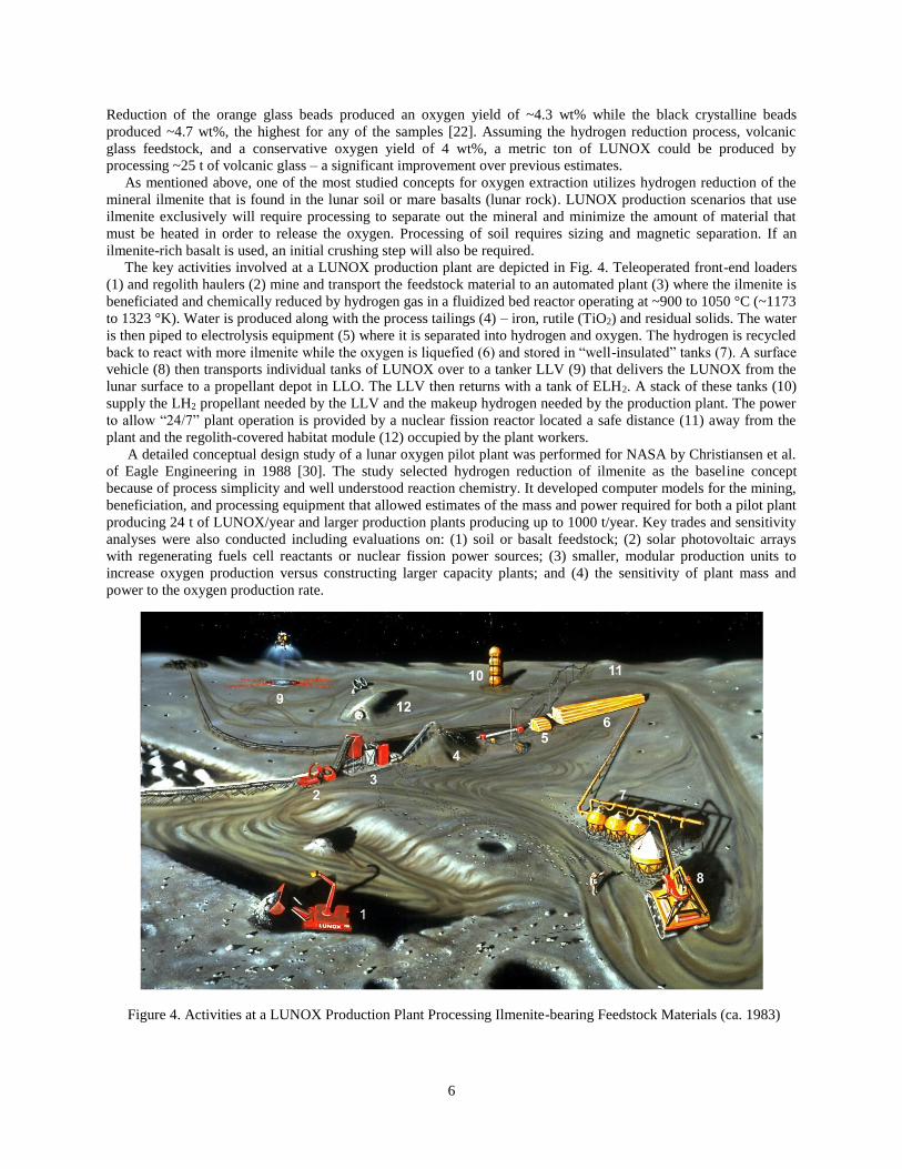
The key activities involved at a LUNOX production plant are depicted in Fig. 4. Teleoperated front-end loaders
(1) and regolith haulers (2) mine and transport the feedstock material to an automated plant (3) where the ilmenite is
beneficiated and chemically reduced by hydrogen gas in a fluidized bed reactor operating at ~900 to 1050 °C (~1173
to 1323 °K). Water is produced along with the process tailings (4) – iron, rutile (TiO2) and residual solids. The water
is then piped to electrolysis equipment (5) where it is separated into hydrogen and oxygen. The hydrogen is recycled
back to react with more ilmenite while the oxygen is liquefied (6) and stored in “well-insulated” tanks (7). A surface
vehicle (8) then transports individual tanks of LUNOX over to a tanker LLV (9) that delivers the LUNOX from the
lunar surface to a propellant depot in LLO. The LLV then returns with a tank of ELH2. A stack of these tanks (10)
supply the LH2 propellant needed by the LLV and the makeup hydrogen needed by the production plant. The power
to allow “24/7” plant operation is provided by a nuclear fission reactor located a safe distance (11) away from the
plant and the regolith-covered habitat module (12) occupied by the plant workers.
A detailed conceptual design study of a lunar oxygen pilot plant was performed for NASA by Christiansen et al.
of Eagle Engineering in 1988 [30]. The study selected hydrogen reduction of ilmenite as the baseline concept
because of process simplicity and well understood reaction chemistry. It developed computer models for the mining,
beneficiation, and processing equipment that allowed estimates of the mass and power required for both a pilot plant
producing 24 t of LUNOX/year and larger production plants producing up to 1000 t/year. Key trades and sensitivity
analyses were also conducted including evaluations on: (1) soil or basalt feedstock; (2) solar photovoltaic arrays
with regenerating fuels cell reactants or nuclear fission power sources; (3) smaller, modular production units to
increase oxygen production versus constructing larger capacity plants; and (4) the sensitivity of plant mass and
power to the oxygen production rate.
Figure 4. Activities at a LUNOX Production Plant Processing Ilmenite-bearing Feedstock Materials (ca. 1983)

7
In the Eagle Engineering study, a three-stage fluidized bed reactor concept [31] was baselined for the ilmenite
reduction process (shown in Fig. 5). The plant is supplied by two teleorobotic regolith haulers. While one hauler is
being filled at the mining site, the other hauler travels to and from the plant. At the plant the hauler (1) dumps its
load into the process feed bin (2) and collects a load of either screened soil or tailings (unprocessed ilmenite, rutile
and iron) from the plant’s discharge bin (3). It then dumps these materials at the appropriate collection area (4) and
returns to the mining site to begin the cycle over again.
From the feed bin a magnetic separator (5) isolates the slightly magnetic ilmenite from the rest of the bulk soil
which is then discarded. The “enriched” ilmenite feedstock is then transported to the top of the processing plant (6)
by a continuous-flow conveyor system. Here in the top bed of the reactor (7), the feedstock is preheated by hot,
recycled hydrogen gas from the middle bed (8) and the electrolysis cell (9). Ilmenite reduction takes place primarily
in the middle reaction bed. Waste heat from the spent solids is extracted and used to preheat the hydrogen stream in
the bottom bed (10) before the material is discharged through a gas/solid separator (11). The water produced in the
middle bed is then dissociated into oxygen and hydrogen in a solid-state electrolysis cell (12) operated at the
reaction temperature. The oxygen is then cooled, liquefied, and stored (13) while the hydrogen is used to preheat
more ilmenite feedstock (9). The process heat required in the reaction bed is provided by electric resistance heaters
(14) that heat the hydrogen stream before it enters the bed.
The 24 t/year LUNOX pilot plant shown in Fig. 5 was sized to fit within a Shuttle payload bay pallet and has an
outer diameter of ~4.3 m and a length of ~13.7 m. The pallet would serve as a strong back and mounting structure
(15) for the processing unit allowing it to be delivered to the lunar surface fully integrated. Once there the unit is
lifted into the vertical position (as shown in Fig. 5) and stabilized. The vertical orientation is required for proper
plant operation and to take advantage of gravity during material processing. Although operations are largely
autonomous, the facility is human-tended so accommodations are provided for human access to different plant
levels. This includes ground level, the mid-level reaction bed location at ~4.6 m (16) and the upper ilmenite feed
location at ~9.2 m (17) along with connecting ladders (18) and guard rails to allow human inspection and
maintenance of the process equipment.
The Eagle Engineering study considered both an “ilmenite-rich” basalt feedstock (containing ~33 wt% ilmenite)
and a soil feedstock (with ~7.5 wt% ilmenite) in assessing plant performance. With basalt feedstock, ~186 t of
mined material is required per ton of LUNOX produced. Using lower ilmenite content, soil feedstock eliminated the
Figure 5. Schematic and Illustration of a LUNOX Pilot Plant Utilizing a
Continuous Fluidized Bed Reactor for Ilmenite Reduction with Hydrogen
8
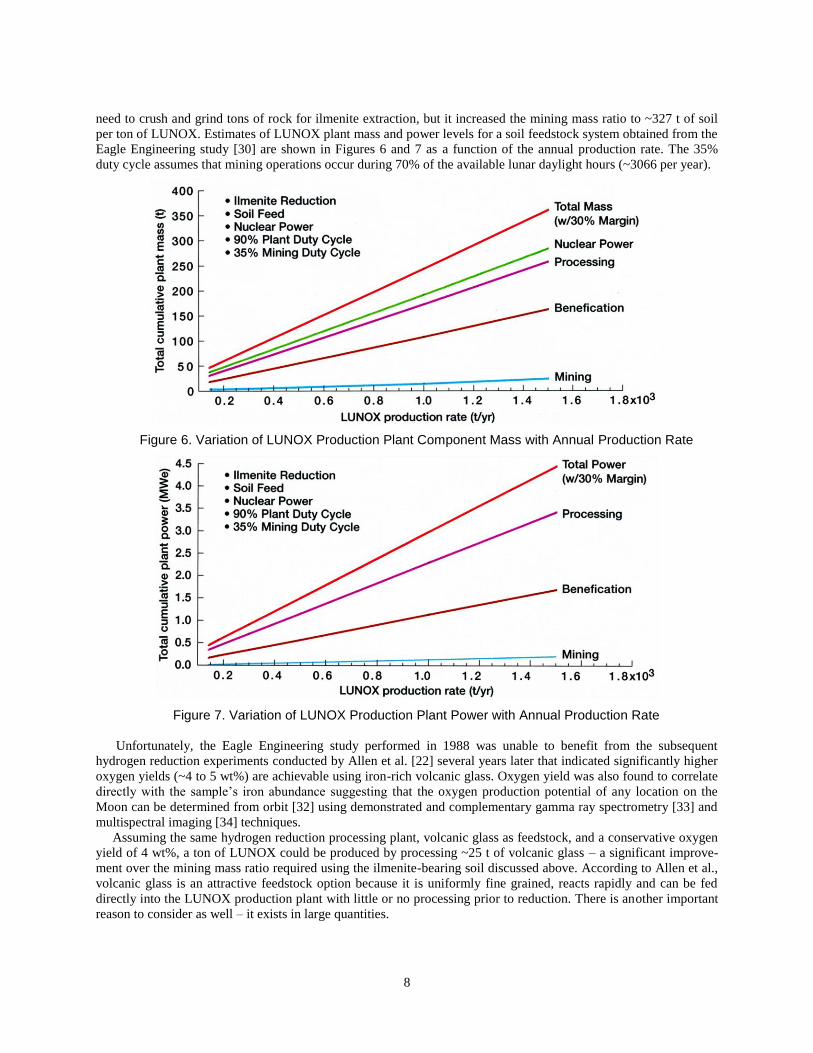
need to crush and grind tons of rock for ilmenite extraction, but it increased the mining mass ratio to ~327 t of soil
per ton of LUNOX. Estimates of LUNOX plant mass and power levels for a soil feedstock system obtained from the
Eagle Engineering study [30] are shown in Figures 6 and 7 as a function of the annual production rate. The 35%
duty cycle assumes that mining operations occur during 70% of the available lunar daylight hours (~3066 per year).
Figure 6. Variation of LUNOX Production Plant Component Mass with Annual Production Rate
Figure 7. Variation of LUNOX Production Plant Power with Annual Production Rate
Unfortunately, the Eagle Engineering study performed in 1988 was unable to benefit from the subsequent
hydrogen reduction experiments conducted by Allen et al. [22] several years later that indicated significantly higher
oxygen yields (~4 to 5 wt%) are achievable using iron-rich volcanic glass. Oxygen yield was also found to correlate
directly with the sample’s iron abundance suggesting that the oxygen production potential of any location on the
Moon can be determined from orbit [32] using demonstrated and complementary gamma ray spectrometry [33] and
multispectral imaging [34] techniques.
Assuming the same hydrogen reduction processing plant, volcanic glass as feedstock, and a conservative oxygen
yield of 4 wt%, a ton of LUNOX could be produced by processing ~25 t of volcanic glass – a significant improve-
ment over the mining mass ratio required using the ilmenite-bearing soil discussed above. According to Allen et al.,
volcanic glass is an attractive feedstock option because it is uniformly fine grained, reacts rapidly and can be fed
directly into the LUNOX production plant with little or no processing prior to reduction. There is another important
reason to consider as well – it exists in large quantities.
9
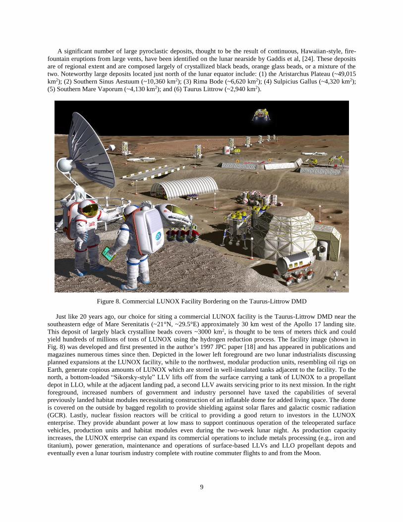
A significant number of large pyroclastic deposits, thought to be the result of continuous, Hawaiian-style, fire-
fountain eruptions from large vents, have been identified on the lunar nearside by Gaddis et al, [24]. These deposits
are of regional extent and are composed largely of crystallized black beads, orange glass beads, or a mixture of the
two. Noteworthy large deposits located just north of the lunar equator include: (1) the Aristarchus Plateau (~49,015
km2); (2) Southern Sinus Aestuum (~10,360 km2); (3) Rima Bode (~6,620 km2); (4) Sulpicius Gallus (~4,320 km2);
(5) Southern Mare Vaporum (~4,130 km2); and (6) Taurus Littrow (~2,940 km2).
Figure 8. Commercial LUNOX Facility Bordering on the Taurus-Littrow DMD
Just like 20 years ago, our choice for siting a commercial LUNOX facility is the Taurus-Littrow DMD near the
southeastern edge of Mare Serenitatis (~21°N, ~29.5°E) approximately 30 km west of the Apollo 17 landing site.
This deposit of largely black crystalline beads covers ~3000 km2, is thought to be tens of meters thick and could
yield hundreds of millions of tons of LUNOX using the hydrogen reduction process. The facility image (shown in
Fig. 8) was developed and first presented in the author’s 1997 JPC paper [18] and has appeared in publications and
magazines numerous times since then. Depicted in the lower left foreground are two lunar industrialists discussing
planned expansions at the LUNOX facility, while to the northwest, modular production units, resembling oil rigs on
Earth, generate copious amounts of LUNOX which are stored in well-insulated tanks adjacent to the facility. To the
north, a bottom-loaded “Sikorsky-style” LLV lifts off from the surface carrying a tank of LUNOX to a propellant
depot in LLO, while at the adjacent landing pad, a second LLV awaits servicing prior to its next mission. In the right
foreground, increased numbers of government and industry personnel have taxed the capabilities of several
previously landed habitat modules necessitating construction of an inflatable dome for added living space. The dome
is covered on the outside by bagged regolith to provide shielding against solar flares and galactic cosmic radiation
(GCR). Lastly, nuclear fission reactors will be critical to providing a good return to investors in the LUNOX
enterprise. They provide abundant power at low mass to support continuous operation of the teleoperated surface
vehicles, production units and habitat modules even during the two-week lunar night. As production capacity
increases, the LUNOX enterprise can expand its commercial operations to include metals processing (e.g., iron and
titanium), power generation, maintenance and operations of surface-based LLVs and LLO propellant depots and
eventually even a lunar tourism industry complete with routine commuter flights to and from the Moon.

10
III. NTR / LANTR System Description and Performance Characteristics
The NTR uses a compact fission reactor core containing “enriched” uranium (U)-235 fuel to generate 100’s of
megawatts of thermal power (MWt) required to heat the LH2 propellant to high exhaust temperatures for rocket
thrust [35]. In an “expander cycle” engine (shown in Fig. 9), high pressure LH2 flowing from a turbopump assembly
(TPA) is split into two paths with the first cooling the engine’s nozzle, pressure vessel, neutron reflector, and control
drums, and the second path cooling the engine’s core support tie-tube assemblies. The flows are then merged and the
heated H2 gas is used to drive the TPAs. The hydrogen turbine exhaust is then routed back into the reactor pressure
vessel and through the internal radiation shield and upper core support plate before entering the coolant channels in
the reactor’s fuel elements. Here it absorbs energy produced from the fission of U-235 atoms, is superheated to high
exhaust temperatures (Tex ~2700 °K or more depending on the uranium fuel loading), then expanded out a high area
ratio nozzle (~300:1) for thrust generation.
Figure 9. Schematic of “Expander Cycle” NTR Engine with Dual LH2 Turbopumps
Controlling the NTR during its various operational phases (startup, full thrust and shutdown) is accomplished by
matching the TPA-supplied LH2 flow to the reactor power level. Multiple control drums, located in the reflector
region surrounding the reactor core, regulate the neutron population and reactor power level over the NTR’s
operational lifetime. The internal neutron and gamma radiation shield, located within the engine’s pressure vessel,
contains its own interior coolant channels. It is placed between the reactor core and key engine components to
prevent excessive radiation heating and material damage.
Recent studies showing the benefits of NTP for a variety of exploration and commercial lunar missions [16,17]
have used a “common” Nuclear Thermal Propulsion Stage (NTPS) employing a cluster of three SNREs. The
engine’s reactor core is composed of hexagonal-shaped fuel elements and core support tie tubes developed and
tested during the Rover/NERVA program [35]. Each fuel element (FE) was fabricated using a “graphite matrix”
material that contained the U-235 fuel in the form of either coated particles of uranium carbide (UC2) or as a
dispersion of uranium and zirconium carbide (UC-ZrC) referred to as “graphite composite” (GC) fuel (see Fig 10).
This higher performance GC fuel was developed as a “drop-in replacement” for the coated particle fuel and was
tested in the Nuclear Furnace element test reactor (NF-1) [34] near the end of the Rover program. The GC elements
achieved a peak power density of ~5 MWt per liter (~5000 MWt/m3) and a peak fuel temperature of ~2700 °K. The
GC elements also demonstrated better corrosion resistance than the standard coated particle fuel elements used in
the previous Rover/NERVA reactor tests. This improved resistance of the GC fuel was attributed to its higher
coefficient of thermal expansion (CTE) that more closely matched that of the protective ZrC coating, thereby
helping to reduce coating cracking. Electrical-heated composite fuel elements were also tested by Westinghouse in
hot hydrogen at 2700 K for ~600 minutes – equivalent to ten 1-hour cycles.
Heritage Rover/NERVA FEs had a hexagonal cross section (~0.75 inch across the flats) and 19 axial coolant
channels (shown in Fig. 10) that were coated with niobium carbide (NbC) initially, then with zirconium carbide
(ZrC) using a chemical vapor deposition (CVD) process. This protective coating, applied to the FE’s exterior
surfaces as well, helped to reduce coating cracking, hydrogen penetration and subsequent erosion of the graphite
matrix material. Individual elements were 1.32 m (52 inches) in length and produced ~1 MWt during steady state,
full power operation. Also included in the engine’s reactor core were hexagonal-shaped tie tube (TT) elements that
provided structural support for 6 surrounding FEs (shown in Fig. 10). A coaxial Inconel tube inside the TT carries

11
hydrogen coolant that is also used to supply a source of heated hydrogen for turbine drive power in the SNRE’s
expander cycle engine design. A sleeve of zirconium hydride (ZrH) moderator material is also incorporated into
each TT (see Fig. 10) to help increase core reactivity and allow construction of smaller, lower thrust engine systems
like the Small Nuclear Rocket Engine (SNRE) [35] developed by Los Alamos National Laboratory near the end of
the Rover/NERVA program.
Although it was not built, the SNRE incorporated all of the lessons learned from the program’s 20 previous
reactor designs and test results. The FE had the same hexagonal cross section and coolant channel number, but was
35 inches long, used GC fuel, and produced ~0.65 MWt. To help increase core reactivity, the “SNRE” FE – TT
pattern increased the number of TTs so that each FE has 3 adjacent TTs and 3 adjacent FEs surrounding it (Fig. 10).
With the SNRE pattern, the FE to TT ratio is ~2 to 1 with each tie tube providing redundant mechanical support for
six surrounding fuel elements.
Figure 10. Coated Particle and Graphite Composite SNRE Fuel Element and Tie Tube Arrangement
The baseline SNRE used in this study has a nominal power output of ~365 MWt, an average power density of
~3.44 MWt/liter, and produces ~16.5 klbf of thrust. The reactor core has 564 fuel elements and 241 tie tubes, and is
surrounded by a 14.7 cm thick perimeter neutron reflector resulting in a pressure vessel diameter of ~98.5 cm. With
a fuel loading of ~0.6 g/cm3, the FEs contain ~60 kg of 93% enriched U-235. The GC fuel operates at a peak
temperature of ~2860 °K and the corresponding hydrogen exhaust temperature is ~2734 °K. With a chamber
pressure of 1000 psia, a hydrogen flow rate of ~8.30 kg/s and a nozzle area ratio (NAR) of ~300:1, the engine’s Isp
is ~900 s. The total engine length is ~5.8 m with the ~1.8 m long radiation-cooled, retractable nozzle section fully
extended. The nozzle exit diameter is ~1.53 m and the engine’s thrust-to-weight ratio is ~3.02.
LANTR: An Enhanced NTR with “Bipropellant” Operational Capability
In order to take full advantage of LUNOX once it becomes available to the LTS, each SNRE is outfitted with an
O2 “afterburner” nozzle containing the O2 injectors and an O2 feed system. The oxygen is stored as a cryogenic
liquid at low pressure and must be pressurized and gasified prior to its injection into the nozzle. This is
accomplished by diverting a small fraction of the engine’s hydrogen flow (~3%) to an oxidizer-rich gas generator
that drives a LO2 TPA used to deliver the gasified LO2 to injectors positioned inside the afterburner nozzle
downstream of the throat [18,19,20]. Here it mixes with the hot H2 and undergoes supersonic combustion adding
both mass and chemical energy to the rocket exhaust – essentially “scramjet propulsion in reverse.”

12
Downstream nozzle injection in LANTR isolates the reactor core from oxygen’s damaging effects provided the
throat retains choked flow. This operating condition can be satisfied by using a “cascade” scramjet injector
developed by Aerojet [20] – now Aerojet Rocketdyne. A 3-zone staged injection approach [20] is envisioned using
multiple cascade injectors to control the oxygen addition and heat release within the nozzle while keeping the flow
supersonic. This approach also increases penetration, mixing and combustion of the injected oxygen within the
hydrogen flow while minimizing shock losses and the formation of high heat flux regions, thereby maximizing
engine performance and life. A high reactor outlet pressure is also desirable since it allows the use of a high area
ratio nozzle – important for increasing combustion efficiency – at reasonable size and mass.
A simplified schematic of LANTR engine operation is illustrated in Fig. 11. Also shown is a photograph of a
non-nuclear, “proof-of-concept” demonstration test of a LANTR nozzle that used a “fuel-rich” 2100 lbf chemical
rocket engine operating at a oxygen/hydrogen MR <2 to simulate a NTR. The water-cooled, copper test nozzle had
NAR of 25:1 and used 3 wedge-shaped injectors (2 of which are visible in Fig. 11) [36]. These tests and follow-on
tests with a 50:1 nozzle indicated that up to 73% of the injected oxygen burned within these short nozzles resulting
in an augmented thrust level of ~53% as measured on the engine thrust stand [20].
Figure 11. Simplified LANTR Schematic and Simulated “Proof-of-Concept” Test Article Photograph [36]
The LANTR concept has the potential to be an extremely versatile propulsion system. By varying the O/H MR,
the LANTR engine can operate over a wide range of thrust and Isp values – shown in Table 1 – while the reactor
core produces a relatively constant power output. As the MR varies from 0 to 5, the engine thrust level for the SNRE
increases by over 344% – from 16.5 klbf to ~56.8 klbf – while the Isp decreases by ~57% – from 900 to 516 s which
is still 54 s higher than that achieved by today’s best LO2/LH2 chemical engine – the RL10B-2 [37]. This thrust
augmentation feature means that “big engine” performance can be obtained using smaller, more affordable LH2-
cooled NTR engines that are easier to build and less costly to test on the ground. The engines can then be operated in
space in the augmented high thrust mode to shorten burn times (thereby extending engine life) and reduce gravity
losses (thereby eliminating the need for and concern over multiple, “perigee burn” Earth departure maneuvers).
Lastly, the increased use of high-density LO2 in place of low-density LH2, and the ability to resupply or “reoxidize”
LANTR vehicles with LUNOX prior to Earth return, are expected to significantly reduce vehicle size and mass
while increasing delivered payload.
Table 1. SNRE / LANTR Performance Characteristics as a Function of O/H Mixture Ratio

13
IV. Mission, Payload and Transportation System Ground Rules and Assumptions
Specific mission and payload ground rules and assumptions used in this paper are summarized in Table 2. It
provides information about the different lunar mission scenarios, along with the assumed parking orbits at Earth and
the Moon. Specific trajectory details and V budgets for the different missions examined are provided within the
appropriate sections of the paper. In addition to the large V requirements for the primary propulsion maneuvers,
like trans-lunar injection (TLI), smaller V maneuvers are needed for propellant settling, vehicle mid-course
correction (MCC) maneuvers, orbital operations in LLO, including rendezvous and docking (R&D) of the LTV with
surface-based LLVs or with the lunar propellant depot, and lastly LTV-depot separation and station keeping.
A variety of different payloads are also considered. On initial “all LH2” NTR crewed landing missions, a forward
mounted saddle truss is used to connect the payload elements to the transfer vehicle’s in-line tank. The truss is open
on its underside and its forward adaptor ring provides a docking interface between the MPCV and the single stage
Table 2. Mission and Payload Ground Rules and Assumptions

14
LO2/LH2 LDAV (shown in Fig. 12a). The LDAV is a “heritage” design [38] analyzed in considerable detail during
NASA’s earlier Space Exploration Initiative (SEI) studies. It carries a crew of 4 plus 5 t of surface payload (PL)
stored in two 2.5 t PL pallets mounted on each side of the crew cab. The LDAV mass breakdown including the
propellant loading and landed payload is shown in Table 2. On the lunar landing mission analyzed here, the crew
also collects and returns ~100 kg of samples.
For the reusable, space-based crewed cargo transport missions using LANTR propulsion and LUNOX on the
Earth return mission leg, the LTV carries a habitat module that supports a crew of 4. Two crewmembers operate the
vehicle and manage the unloading of the PL. The other 2 represent rotating crewmembers on assignment at the lunar
base or the LLO transportation node / propellant depot. Connecting the habitat module to the rest of the LANTR
LTV is a “star truss” that has four concave sides to accommodate four PL pallets (shown in Fig. 12b). The forward
circular truss ring also has a Remote Manipulator System (RMS) with twin arms attached to it. Using the habitat
module’s rear viewing window, the crew uses these arms to unload and attach the transport’s cargo to the depot
node or to a co-orbiting LLV transferring crew and awaiting cargo delivery.
Figure 12. Payload Elements Carried by the NTR and LANTR Lunar Transfer Vehicles
Using the same LANTR LTV system elements shown in Fig. 13, routine commuter flights to and from the Moon
can also be considered. For the commuter shuttle application, the cargo transport’s habitat module, star truss and PL
pallets are removed and replaced with a PTM (Fig. 12c) that carries 18 passengers and 2 crew members. It is also
possible to deliver a 7.5 t shipping container carrying 5 t of priority cargo (Fig. 12d) on the alternating outbound and
inbound legs of the same mission which will be discussed later in the paper.
Table 3 lists the key ground rules and assumptions used in the NTR / LANTR transportation system elements.
The NTPS carries only ELH2 and uses a three-engine cluster of SNRE-class engines initially before transitioning
over to LANTR operation. The smaller diameter in-line LO2 tank located forward of the NTPS carries Earth-
supplied LO2 on the way out to the Moon but refuels with LUNOX for the return to Earth. Details on the NTR and
LANTR engine design and performance are provided in Sect. II and are summarized in Table 3. The total mission
LH2 and LO2 propellant loadings consist of the usable propellant plus performance reserve and tank-trapped
residuals. Additional LH2 is also provided for engine cooldown after each major propulsive maneuver.

15
Figure 13. Key LANTR LTV System Elements – the LH2 NTPS and In-Line LO2 Tank
Table 3. NTR and LANTR Transportation System Ground Rules and Assumptions

16
For the smaller auxiliary maneuvers performed, a storable bipropellant Reaction Control System (RCS) with
AMBR thrusters is used (details in Table 3). The LANTR LTV utilizes a split RCS with approximately half the
AMBR thrusters and bipropellant mass located on the rear NTPS and the other half located at the front end of the in-
line LO2 tank just behind the mission-specific payload.
The LH2 propellant carried in the NTPS is stored in the same “state-of-the-art” Al/Li LH2 propellant tank being
developed for the SLS/HLV to support future human exploration missions. Sizing of the LH2 tank assumes a 30 psi
ullage pressure, 5 gE axial / 2.5 gE lateral launch loads, and a safety factor of 1.5. A 3% ullage factor is also
assumed. The in-line LO2 tank with its rear conical adaptor section uses the same sizing and launch load
assumptions. All tanks use a combination spray-on foam (SOFI) / multilayer insulation (MLI) system for passive
thermal protection. A zero boil-off (ZBO) “reverse turbo-Brayton” cryocooler system is used on the NTPS to
eliminate boil-off after the NTPS has been refueled with ELH2 and during the course of the mission. A passive
thermal protection system is used on the in-line LO2 tank since it is drained after the lunar orbit insertion (LOI) burn
and is subsequently refueled with LUNOX before the trip back to LEO. The heat load on the NTPS hydrogen tank is
largest in LEO and sizes the ZBO cryocooler system. Two sets of circular solar photovoltaic arrays (PVAs) – each
producing ~14 kWe – are baselined with one set supplying the primary electrical power needed for all key LTV sub-
systems and the second set providing power for the different mission payloads considered here.
Table 3 also provides the assumed “dry weight contingency” (DWC) factors, along with the requirements for
delivered mass to LEO and the shroud cylindrical payload envelope for the upgraded SLS / HLV. A 30% DWC is
used on the NTR and LANTR systems and advanced composite structures (e.g., stage adaptors, trusses) and 15% on
heritage systems (e.g., Al/Li tanks, RCS, etc.). The NTPS mass (~70 t) and size (~7.6 m OD and ~26.5 m length)
determines the required lift capability and the usable shroud PL volume for the upgraded SLS. The combined saddle
truss (~13.7 m) and LDAV (~9.6 m) used on the crewed landing mission (shown below in Fig. 14b) has this same
approximate length. On the crewed cargo transport mission discussed in Sect. VII, the habitat module (~6.5 m OD
and ~8.5 m in length) and star truss (~11 m in length) can be launched together, or the truss can be launched together
with the in-line LO2 tank and its conical adaptor (~11.5 m in length).
V. Performance Impact of Integrating LANTR and LUNOX into the LTS Architecture
As mentioned in the Introduction, the author presented a paper on the enhanced mission capability resulting from
the combined use of LANTR propulsion and LUNOX 20 years ago at the 33rd Joint Propulsion Conference in
Seattle, Washington [18]. In that paper, an evolutionary LTS architecture was analyzed that began with a LTS using
high performance NTP to maximize delivered surface payload on each mission. The increased PL was dedicated to
installing modular LUNOX production units with the intent of using this LDP to supply surfaced-based LLVs
initially, then in-space LTVs using LANTR propulsion at the earliest possible opportunity. This section re-examines
this evolutionary LTS architecture to see how recent NLTV designs and missions [16,17] are impacted by the
introduction of LANTR and LUNOX.
Figure 14. Reusable NTR Cargo Delivery and Crewed Lunar Landing Vehicles
The NTPS, with its three 16.5 klbf SNREs, is the “workhorse” element on the cargo and crewed NLTVs shown in
Figs. 14a and 14b. It has a 7.6 m diameter by ~15.7 m long Al/Li tank that carries ~39.8 t of LH2 propellant. Housed
within and mounted on the forward cylindrical adaptor section of the NTPS are the RCS, avionics, batteries, two
deployable circular PVAs, a docking system, along with a reverse turbo-Brayton cryocooler system for zero boil-off

17
LH2 storage. The cryocooler system mass and power requirements increase with tank diameter and are sized to
remove ~42 watts of heat penetrating the 60 layer MLI system while the stage is in LEO where the highest tank heat
flux occurs. To remove this heat load, the 2-stage cryocooler system requires ~5.3 kWe for operation
The second major element is an “in-line” Al/Li propellant tank that connects the NTPS to the forward PL
element. It has the same diameter and length LH2 tank as that used in the NTPS and supplies an additional ~39.8 t of
LH2 propellant used during for the “2-perigee burn” TLI maneuver. The in-line tank element also includes forward
and aft cylindrical adaptor sections that house quick connect/disconnect propellant feed lines, electrical connections,
a RCS along with docking and payload adaptors. A ZBO cryocooler system is not used on the in-line LH2 tank since
it is drained during the TLI maneuver. The total length of the in-line element is ~20.7 m.
Reusable Lunar Cargo Delivery / Propellant Tanker Missions
Using the NTPS and in-line tank discussed above, the cargo transport can deliver an ~64.5 t fully integrated
habitat lander with surface mobility to LLO then return to Earth for refueling and reuse. Three SLS-1B launches
deliver the vehicle and payload elements to LEO where assembly occurs via autonomous R&D. The cargo transport
then departs from LEO (C3 ~ -1.678 km2/s2, VTLI ~3.214 km/s including a g-loss of ~117 m/s) and captures into a
300-km circular LLO (arrival C3 ~1.151 km2/s2 and VLOC ~906 m/s including g-loss) approximately 72 hours later.
Once in orbit, the habitat lander separates from the cargo transport (shown in Fig. 14a) and descends to the
surface, landing autonomously at a predetermined location on the Moon. The habitat lander uses LO2/LH2 chemical
engines and is equipped with either wheels or articulated landing gear allowing movement in both the vertical and
horizontal directions so the lander can either “drive or walk” short distances from the landing site. Assuming a
LUNOX production plant and lander can be configured to fit within the SLS-1B PL shroud, the habitat lander can be
replaced by a 36 t “wet” LLV stage capable of delivering ~28 t from LLO to the lunar surface. According to Fig. 7,
a LUNOX plant mass of ~28 t corresponds to a production capacity of ~175 t/year assuming volcanic glass as
feedstock. This mass includes the mining and processing equipment with a 30% margin but does not include any
beneficiation hardware. The fission surface power system mass is also not included here because it is delivered and
pre-deployed on an earlier mission. Without any attached PL, the cargo NLTV can also function as a propellant
“tanker” delivering ~25.6 t of LH2 to a LLO depot on each roundtrip mission.
After payload separation and a day in LLO, the cargo transport performs a trans-Earth injection (TEI) burn (C3 ~
0.945 km2/s2, VTEI ~857 m/s including g-loss) and returns to Earth 72 hours later. On final approach, it performs a
braking burn (arrival C3 ~ -1.755 km2/s2, VEOC ~366 m/s) and captures into a 24-hour EEO with a 500 km perigee
x 71,136 km apogee. Post burn engine cool-down thrust is then used to assist in orbit lowering. Afterwards, an
auxiliary tanker vehicle, operating from a LEO servicing node/propellant depot, rendezvouses and docks with the
cargo vehicle and supplies it with the additional LH2 propellant needed for final orbit lowering and rendezvous with
the LEO transportation node where it is refurbished and resupplied before its next mission.
The cargo NLTV has an IMLEO of ~187.8 t consisting of the NTPS (~68.3 t), the in-line tank element (~52 t),
and the habitat lander (~64.5 t) with its connecting structure (~3.0 t). The mission requires five primary burns by the
SNRE engines that use ~74.8 t of LH2 propellant. With ~49.5 klbf of total thrust and Isp ~900 s, the total engine burn
time is ~50 minutes. For the propellant tanker mission, the IMLEO is ~121.2 t and the total engine burn time is ~34
minutes.
Reusable Crewed Lunar Landing Mission
On the crewed landing mission, the NLTV carries a forward mounted saddle truss that connects the payload
elements to the transfer vehicle’s in-line tank. The truss is open on its underside and its forward adaptor ring
provides a docking interface between the Orion MPCV and the single stage LOX/LH2 LDAV as shown in Fig. 14b.
The LDAV carries a crew of 4 plus 5 t of surface payload stored in two “swing-down” pallets mounted on each side
of the crew cab (shown in Fig. 15b).
Three SLS-1B launches are used to deliver the two NTR vehicle elements and the payload element to LEO for
assembly via autonomous R&D. The payload element consists of the integrating saddle truss assembly (STA) plus
the LDAV with its surface cargo containers. In addition to a front and rear docking capability, the STA’s forward
adaptor ring also carries twin PVAs and a RCS. Once assembled, the Orion MPCV and crew are launched and
rendezvous with the NLTV positioning itself inside the STA and docking with the LDAV using the docking port
and transfer tunnel mounted to the STA’s forward adaptor ring (shown in Fig. 12a).

18
After the “2-perigee burn” TLI burn (C3 ~ -1.516 km2/s2, VTLI ~3.214 km/s including a g-loss of ~110 m/s), the
crew begins its 3-day coast to the Moon. Although the crewed NLTV carries a significant amount of payload mass
(the STA, MPCV, and “spent” LDAV) back from the Moon, it uses the same ~15.7 m long in-line tank to supply the
required amount of LH2 propellant needed for this reusable mission. After its 72-hour transit, the NLTV performs
the lunar orbit capture (LOC) burn (arrival C3 ~1.217 km2/s2 and VLOC ~913 m/s including g-loss) inserting itself
and its payload into LLO.
Figure 15. Crewed Lunar Landing Mission: Transfer Vehicle Capture into LLO and LDAV Landing Preparation
Once in LLO, the crew enters the LDAV and separates from the transfer vehicle. After separation, the LDAV’s
two payload pallets are rotated 180 degrees and lowered into their landing position in preparation for descent to the
lunar surface (Fig. 15b). The V budget used in the Martin Marietta LDAV design [38] isVdes ~2.115 km/s and
Vasc ~1.985 km/s. The LDAV uses five RL10A-4 engines operating with a Isp~450 s and ~13.5 t of LO2/LH2
propellant is expended during the descent to the surface.
After completing the surface mission, the crew returns to LLO in the LDAV carrying 100 kg of lunar samples. At
liftoff, the LDAV mass is ~15.1 t and ~5.5 t of propellant is used during the ascent to LLO. The LDAV then
rendezvous with the transfer vehicle and preparations for the TEI maneuver begin. After completing the departure
burn (C3 ~ 0.949 km2/s2, VTEI ~856 m/s with g-loss), the crew spends the next 3 days in transit readying their
vehicle for the final phase of the mission – capture into a 24-hr EEO (arrival C3 ~ -1.740 km2/s2, VEOC ~367 m/s).
Afterwards, the crew re-enters and lands using the Orion capsule.
The crewed lunar landing mission has an IMLEO of ~176.6 t that includes the NTPS (~68.7 t), the in-line tank
assembly (~51.8 t), the STA (~7.2 t), the wet LDAV (~29.5 t) with its surface payload (~5 t), the Orion MPCV
(~13.5 t), consumables (~0.1 t), and 4 crewmembers (~0.8 t includes lunar EVA suits). At departure, the LH2
propellant loading in the NTPS and the in-line tank are at their maximum capacity of ~39.8 t. The overall length of
the crewed NLTV is ~74 m. Like the cargo mission, the crewed landing mission requires 5 primary burns by the
NTPS using ~74.8 t of LH2 propellant, and the total engine burn time is again ~50 minutes.
Impact of Using LUNOX to Refuel Surface-based LDAVs and In-Space NLTVs
Figure 16 shows the variation in NLTV size, IMLEO, increased mission capability and engine burn time
resulting from the development and utilization of LLO2. Figure 16a shows the reusable, crewed NLTV discussed
above. It departs from LEO and captures into a 300-km equatorial LLO. At the end of the mission, the NLTV
returns to Earth with the spent LLV and captures into a 24-hr EEO because it has a much lower V requirement. In
order to return to LEO, the NLTV would need an additional ~118 t of LH2 propellant requiring the insertion of a star
truss with four attached drop tanks between the vehicle’s in-line tank and forward payload. The additional mass of
the extra truss, propellant and tanks nearly doubles the vehicle’s IMLEO to ~347.8 t!
The first significant step in LUNOX production occurs when lunar outpost assets and LLO2 production levels
become sufficient to support a lunar surface-based LDAV. By not having to transport a “wet” LDAV to LLO on
each flight, the crewed NLTV now has a lower starting mass in LEO (~146 t) plus sufficient onboard propellant to
allow a single burn departure from LEO and a return to a lower, higher energy ~3.25-hr EEO (407 km perigee x
9,050 km apogee with VEOC ~1793 m/s including a g-loss of ~35 m/s) as shown in Figure 16b.
19
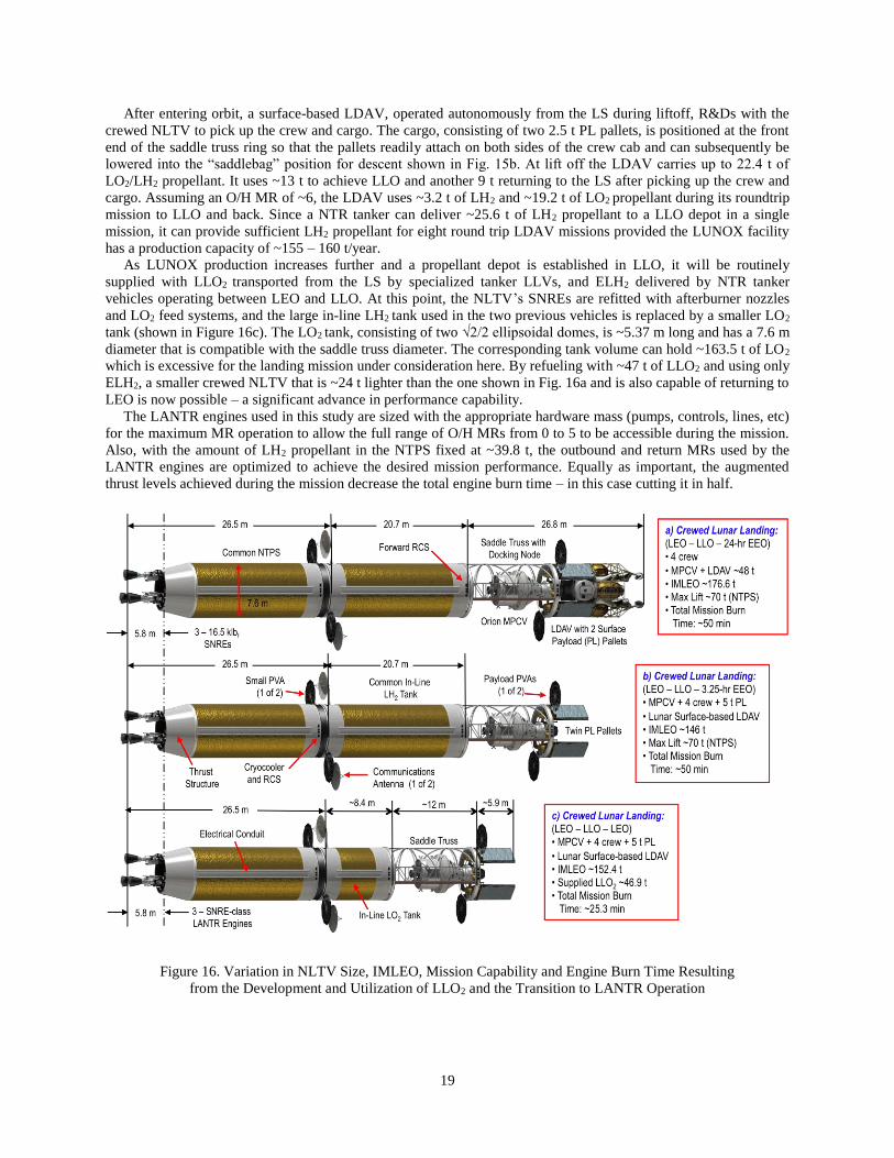
After entering orbit, a surface-based LDAV, operated autonomously from the LS during liftoff, R&Ds with the
crewed NLTV to pick up the crew and cargo. The cargo, consisting of two 2.5 t PL pallets, is positioned at the front
end of the saddle truss ring so that the pallets readily attach on both sides of the crew cab and can subsequently be
lowered into the “saddlebag” position for descent shown in Fig. 15b. At lift off the LDAV carries up to 22.4 t of
LO2/LH2 propellant. It uses ~13 t to achieve LLO and another 9 t returning to the LS after picking up the crew and
cargo. Assuming an O/H MR of ~6, the LDAV uses ~3.2 t of LH2 and ~19.2 t of LO2 propellant during its roundtrip
mission to LLO and back. Since a NTR tanker can deliver ~25.6 t of LH2 propellant to a LLO depot in a single
mission, it can provide sufficient LH2 propellant for eight round trip LDAV missions provided the LUNOX facility
has a production capacity of ~155 – 160 t/year.
As LUNOX production increases further and a propellant depot is established in LLO, it will be routinely
supplied with LLO2 transported from the LS by specialized tanker LLVs, and ELH2 delivered by NTR tanker
vehicles operating between LEO and LLO. At this point, the NLTV’s SNREs are refitted with afterburner nozzles
and LO2 feed systems, and the large in-line LH2 tank used in the two previous vehicles is replaced by a smaller LO2
tank (shown in Figure 16c). The LO2 tank, consisting of two √2/2 ellipsoidal domes, is ~5.37 m long and has a 7.6 m
diameter that is compatible with the saddle truss diameter. The corresponding tank volume can hold ~163.5 t of LO2
which is excessive for the landing mission under consideration here. By refueling with ~47 t of LLO2 and using only
ELH2, a smaller crewed NLTV that is ~24 t lighter than the one shown in Fig. 16a and is also capable of returning to
LEO is now possible – a significant advance in performance capability.
The LANTR engines used in this study are sized with the appropriate hardware mass (pumps, controls, lines, etc)
for the maximum MR operation to allow the full range of O/H MRs from 0 to 5 to be accessible during the mission.
Also, with the amount of LH2 propellant in the NTPS fixed at ~39.8 t, the outbound and return MRs used by the
LANTR engines are optimized to achieve the desired mission performance. Equally as important, the augmented
thrust levels achieved during the mission decrease the total engine burn time – in this case cutting it in half.
Figure 16. Variation in NLTV Size, IMLEO, Mission Capability and Engine Burn Time Resulting
from the Development and Utilization of LLO2 and the Transition to LANTR Operation
20
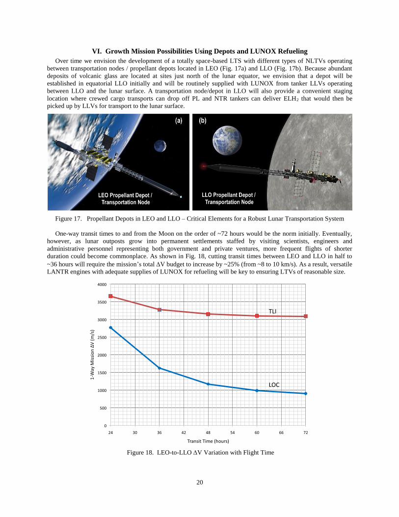
VI. Growth Mission Possibilities Using Depots and LUNOX Refueling
Over time we envision the development of a totally space-based LTS with different types of NLTVs operating
between transportation nodes / propellant depots located in LEO (Fig. 17a) and LLO (Fig. 17b). Because abundant
deposits of volcanic glass are located at sites just north of the lunar equator, we envision that a depot will be
established in equatorial LLO initially and will be routinely supplied with LUNOX from tanker LLVs operating
between LLO and the lunar surface. A transportation node/depot in LLO will also provide a convenient staging
location where crewed cargo transports can drop off PL and NTR tankers can deliver ELH2 that would then be
picked up by LLVs for transport to the lunar surface.
Figure 17. Propellant Depots in LEO and LLO – Critical Elements for a Robust Lunar Transportation System
One-way transit times to and from the Moon on the order of ~72 hours would be the norm initially. Eventually,
however, as lunar outposts grow into permanent settlements staffed by visiting scientists, engineers and
administrative personnel representing both government and private ventures, more frequent flights of shorter
duration could become commonplace. As shown in Fig. 18, cutting transit times between LEO and LLO in half to
~36 hours will require the mission’s total V budget to increase by ~25% (from ~8 to 10 km/s). As a result, versatile
LANTR engines with adequate supplies of LUNOX for refueling will be key to ensuring LTVs of reasonable size.
Figure 18. LEO-to-LLO V Variation with Flight Time

21
VII. Conestoga - A Reusable, Space-based Crewed Cargo Transport
The original Conestoga wagon was a freight wagon developed in Lancaster County, Pennsylvania in the early
1700s [39] and used extensively in Pennsylvania and the nearby states of Maryland, Ohio and Virginia for more than
150 years. It was designed for hauling heavy loads – up to 6 tons – and had a distinctive bed that was curved upward
at both ends to prevent the wagon’s contents from shifting or falling out while traveling over rough roads. A white
canvas cover protected the wagon’s contents from inclement weather and a team of four to six strong horses pulled
the wagon some 12 to 14 miles a day (shown in Fig. 19).
Figure 19. Conestoga Wagons, the “Ships of Inland Commerce,” were used to Transport Settlers,
Farm Produce, and Freight across Pennsylvania and Neighboring States (Image ca 1910) [40]
Named after its earlier ancestor, the Conestoga crewed cargo transport shown in Fig. 20 is a space-based,
reusable LTV that uses LANTR propulsion and refuels with LUNOX propellant. Conestoga has its own dedicated
habitat module that supports a crew of 4 and has a mass of ~10 t. Two crewmembers operate the vehicle and manage
the unloading of the PL. The other 2 represent rotating crewmembers on assignment at the lunar base or the LLO
transportation node / propellant depot. Connecting the habitat module to the rest of the LANTR LTV is a 4-sided
star truss that has four PL pallets attached to it – each weighing up to ~2.5 t. To accommodate the wedge-shaped
geometry of the cargo pallets, the sides of the star truss are concave – a feature similar to the upward curving ends of
the Conestoga wagon’s bed though not for the same design reason. Attached to the star truss’ forward circular ring is
a RMS with twin arms that are free to move around the ring’s outer perimeter (Fig. 20). Using the habitat module’s
rear viewing window, the crew uses these manipulator arms to unload and attach the Conestoga’s cargo to either the
depot node or to a co-orbiting LDAV transferring crew and awaiting cargo delivery. Key features and dimensions of
the Conestoga are shown in Fig. 21 and major mission activities are shown in Fig. 22.
Figure 20. Conestoga - A Space-based Crewed Cargo Transport uses a Common NTPS and In-Line LO2 Tank
22
Figure 21. Key Features and Dimensions for the Conestoga Crewed Cargo Transport (CCT)
The Conestoga CCT is a versatile vehicle that can deliver varying amounts of cargo (from 10 to 40 t) to LLO
depending on the transit times out and back. Once loaded with cargo at the LEO transportation node, the Conestoga
leaves orbit for the Moon. After braking into LLO, the Conestoga’s cargo is then unloaded and attached to the
LDAV using the vehicle’s RMS as shown in Fig. 22. The Conestoga can also be used as a tanker vehicle
transferring close to 10 t of LH2 from it NTPS to the depot. Outfitted with appropriate refueling appendages,
Conestoga could also supply LH2 propellant directly to the LDAV. Refueling ports and twin PVAs are located at the
forward ends of the NTPS and in-line LO2 tank assembly for refueling in LEO and LLO, and for powering the
NTPS and forward PL element as shown in Fig. 21.
In this study, the Conestoga’s NTPS is limited to a LEO launch mass of ~70 t which includes ~39.8 t of LH2
contained in the NTPS’s propellant tank. With this fixed value, the outbound and return MRs used by the LANTR
engines are optimized to achieve the desired mission performance. A mission analysis and vehicle sizing code with
optimization capability [41] is used to determine the customized LO2 tank size and LUNOX refueling requirement
for a particular mission application, or for a fixed LO2 tank size to determine the maximum delivered payload and
LUNOX refueling needed for a desired trip time. For a fixed LO2 tank size and PL, the shortest trip time and
LUNOX refueling needed can also be determined. A variety of other trades have also been conducted.
Figure 22. Conestoga Crewed Cargo Transport Mission - Outbound Leg and LLO Operations

23
Table 4. LANTR Crewed Cargo Missions, Trajectory and V Budgets, and LUNOX Refueling Needs
Table 4 provides a sampling of different crewed cargo missions, vehicle types and trip times that have been
examined along with the associated LUNOX refueling requirements. All the cases shown use the same common
3-engine NTPS described previously in Sect. IV and shown in Figure 21. Case 1, the crewed lunar landing mission
discussed in Sect. V and shown in Fig. 16c, carries the Orion MPCV and 5 t of cargo. It uses an oversized in-line
LO2 tank consisting of two 7.6 m diameter ellipsoidal domes and requires ~47 t of LUNOX for Earth return. Case 2
is a space-based crewed cargo transport (CCT) similar to Conestoga. It has its own dedicated habitat module
weighing 9.9 t, plus a star truss that has two 2.5 t PL pallets attached to it. The LO2 tank is smaller (~4.6 m outer
diameter (OD) and ~3.4 m in length (L)) and is customized for this particular application resulting in a lower
IMLEO (~131 t) and LUNOX refueling requirement (~35 t).
Case 3 shows the impact on CCT sizing of reducing the LEO-LLO transit time from 72 hours down to 36 hours.
Cutting the transit time in half increases the total mission V by ~23% and increases the IMLEO by ~46 t. Also,
because the LH2 propellant loading in the NTPS is fixed at ~39.8 t for these missions, the LANTR engines run at
higher O/H MRs increasing the in-line LO2 tank length to ~6.1 m and the LUNOX refueling requirement for Case 3
to ~71.6 t – more than double that needed for Case 2.
Case 4 not only cuts the “1-way” transit times to 36 hours but it also doubles the amount of cargo delivered to the
LLO to 10 t. To meet these demanding mission objectives, the LANTR engines run “O2-rich” on both the outbound
mission leg (MR = 5, Isp ~516 s for TLI; MR = 4.1, Isp ~550 s for LOC) and return mission leg (MR = 5, Isp ~516 s
for both the TEI and EOC burns). Case 4 is the defining mission used to establish the required performance and
sizing for the Conestoga crewed cargo transport. The LO2 tank length increases to 7.95 m and it holds ~111.2 t of
LO2 just prior to mission start. This tank length is fixed for all subsequent Conestoga-class missions. After dropping
off its cargo and picking up 250 kg of lunar samples, Conestoga refuels with ~74.9 t of LUNOX for the return trip
home. For this mission, Conestoga has an IMLEO of ~214.3 t consisting of the NTPS (~71 t), the in-line LO2 tank
and conical adaptor (~117.2 t), the star truss assembly with its RMS (~5.3 t) and attached PL (10 t), the habitat
module (9.9 t), consumables (~0.1 t) plus the 2 crew and 2 passengers with their EVA suits (~0.8 t). The total
mission V to go from LEO to LLO then back to LEO again is ~9.92 km/s including g-losses. With the augmented
24
thrust levels provided by the LANTR engines (~56.8 klbf per engine at MR = 5), the burn times for the individual
maneuvers are ~11.5 min (TLI), ~3.8 min (LOC), ~4.4 min (TEI), and ~5.6 min (EOC) totaling to ~25.3 minutes.
This total burn time is essentially fixed by the available amount of LH2 in the NTPS and the specified LH2 flow
rate for each engine of ~8.3 kg/s. What varies in the different cases presented in this paper is the amount of LO2
supplied in LEO and LLO and the different MRs used by the LANTR engines to achieve the mission objectives.
Case 5 illustrates the mission flexibility with the Conestoga CCT and its LANTR engines. With its fixed size
tanks able to carry ~39.8 t of LH2 and up to ~111.2 t of LO2, Conestoga can operate as both a cargo delivery and
tanker vehicle. By increasing the LEO to LLO transit time back to 72 hours, and operating the LANTR engines
O2-rich both out and back (again at MR = 5 and Isp ~516 s), Conestoga can deliver 10 t of cargo and transfer ~9.62 t
of LH2 propellant from its NTPS to the LLO depot. For the return trip back to LEO, it refuels with ~54 t of LUNOX.
The IMLEO required for this mission is ~194.1 t and the total mission V is ~8.04 km/s. The burn times for the
individual maneuvers are 9.9 min (TLI), ~1.9 min (LOC), ~2.1 min (TEI), and ~5.2 min (EOC) totaling to ~19.1
minutes. By transferring ~9.6 t of LH2 propellant from the NTPS during this mission, there is less available for the
engines to use so the total mission burn time decreases and the LANTR engines operate at M = 5 to compensate.
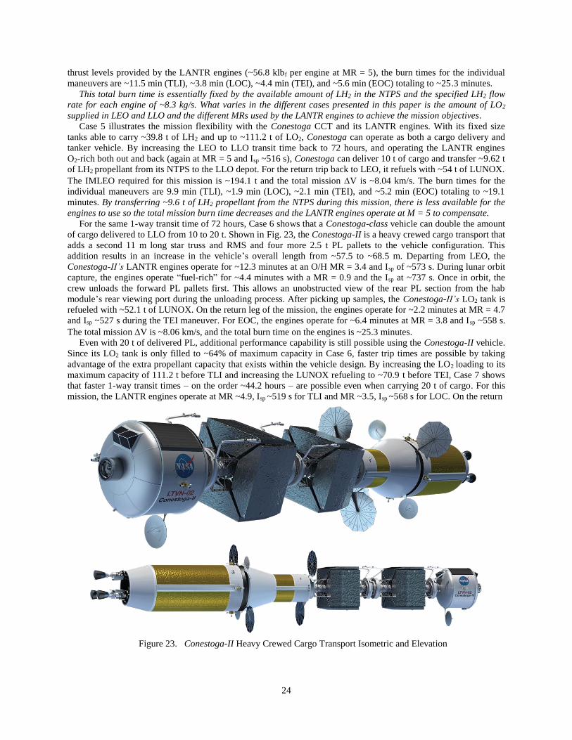
For the same 1-way transit time of 72 hours, Case 6 shows that a Conestoga-class vehicle can double the amount
of cargo delivered to LLO from 10 to 20 t. Shown in Fig. 23, the Conestoga-II is a heavy crewed cargo transport that
adds a second 11 m long star truss and RMS and four more 2.5 t PL pallets to the vehicle configuration. This
addition results in an increase in the vehicle’s overall length from ~57.5 to ~68.5 m. Departing from LEO, the
Conestoga-II’s LANTR engines operate for ~12.3 minutes at an O/H MR = 3.4 and Isp of ~573 s. During lunar orbit
capture, the engines operate “fuel-rich” for ~4.4 minutes with a MR = 0.9 and the Isp at ~737 s. Once in orbit, the
crew unloads the forward PL pallets first. This allows an unobstructed view of the rear PL section from the hab
module’s rear viewing port during the unloading process. After picking up samples, the Conestoga-II’s LO2 tank is
refueled with ~52.1 t of LUNOX. On the return leg of the mission, the engines operate for ~2.2 minutes at MR = 4.7
and Isp ~527 s during the TEI maneuver. For EOC, the engines operate for ~6.4 minutes at MR = 3.8 and Isp ~558 s.
The total mission V is ~8.06 km/s, and the total burn time on the engines is ~25.3 minutes.
Even with 20 t of delivered PL, additional performance capability is still possible using the Conestoga-II vehicle.
Since its LO2 tank is only filled to ~64% of maximum capacity in Case 6, faster trip times are possible by taking
advantage of the extra propellant capacity that exists within the vehicle design. By increasing the LO2 loading to its
maximum capacity of 111.2 t before TLI and increasing the LUNOX refueling to ~70.9 t before TEI, Case 7 shows
that faster 1-way transit times – on the order ~44.2 hours – are possible even when carrying 20 t of cargo. For this
mission, the LANTR engines operate at MR ~4.9, Isp ~519 s for TLI and MR ~3.5, Isp ~568 s for LOC. On the return
Figure 23. Conestoga-II Heavy Crewed Cargo Transport Isometric and Elevation

25
leg, the engines operate at MR = 5, Isp ~516 s for both the TEI and EOC burns. The IMLEO for the Conestoga-II’s
fast 20 t cargo delivery mission is ~230 t, the total mission V is ~9.02 km/s, and the total mission burn time is
again ~25.3 minutes. The burn times for the individual maneuvers are ~12.2 min (TLI), ~3.6 min (LOC), ~3.6 min
(TEI), and ~5.9 min (EOC).
Case 8 pushes the Conestoga-II’s cargo delivery capability to its limit for the amount of LH2 and LO2 propellant
available in the NTPS and in-line LO2 tank. Assuming 72-hour transit times, this limit is ~40 t (eight 5 t PL pallets).
For this mission, the LO2 loading at LEO departure is ~109.8 t (~98.5% of the tank’s maximum capacity) and the
LANTR engines are operated at MR ~4.4, Isp ~536 s for TLI and MR ~3.3, Isp ~578 s for LOC. On the return leg, the
Conestoga-II is refueled with ~60.3 t of LUNOX and its engines are operated at MR = 5, Isp ~536 s for TEI and MR
~4.8, Isp ~522 s for LOC. These MR conditions were selected by the optimizer to deliver the specified PL while also
minimizing the total LO2 requirement for the mission. The IMLEO for Case 8 is ~250.7 t and the total mission V is
~8.06 km/s. The total mission burn time of ~25.3 minutes includes the following individual burn times: ~13.8 min
(TLI), ~3.2 min (LOC), ~2.3 min (TEI), and ~6 min (EOC).
The Conestoga-class CCTs shown departing LEO for the Moon in Fig. 24 can provide the basis for a robust and
flexible LTS that offers a wide range of cargo delivery capability and transit times made possible through the use of
LANTR propulsion and supplies of LUNOX provided in LLO. Today, “time is money” for the long distance freight
haulers traveling our highways, oceans and skies. In the future, Conestoga-class vehicles could play the same
important role in establishing cislunar trade and commerce as the Conestoga wagons of old did for more than a
century throughout Pennsylvania and its neighboring states.
Figure 24. Conestoga-class Crewed Cargo Transports Departing LEO for the Moon
VIII. Commuter Shuttle and Priority Cargo Delivery
In the movie 2001: A Space Odyssey, released by MGM in 1968 [42], Dr. Heywood Floyd departs from a huge
artificial gravity space station orbiting Earth bound for the Moon. He arrives there 24 hours later [43] aboard a large
spherical-shaped LTV called Ares which touches down on a landing pad that subsequently descends to a large
sprawling lunar settlement located underground. Today, almost 50 years later, the images portrayed in Stanley
Kubrick and Arthur C. Clarke’s film remain well beyond our capabilities and 2100: A Space Odyssey seems a more
appropriate title for the movie. In this section, we evaluate the feasibility and requirements for commuter flights and
priority cargo delivery using LANTR propulsion and LUNOX propellant to see if the operational capabilities
presented in 2001 can be achieved albeit on a more “Spartan” scale.
A 24-hour commuter flight to the Moon is a daunting challenge. This is about the time it now takes to fly from
Washington, D. C. to Melbourne, Australia with a 3-hour layover in San Francisco. As Fig. 18 shows, decreasing the
LEO-to-LLO transit time from 72 to 24 hours increases the outbound V requirement from ~4 to 6.4 km/s and the
total roundtrip V requirement by ~4.8 km/s! Increasing the flight time to 36 hours each way decreases this
additional V requirement by 37.5% – to ~1.8 km/s. Also, at these higher velocities, free return trajectories are no
longer available so multiple engines will be required to improve reliability and increase passenger safety.
26
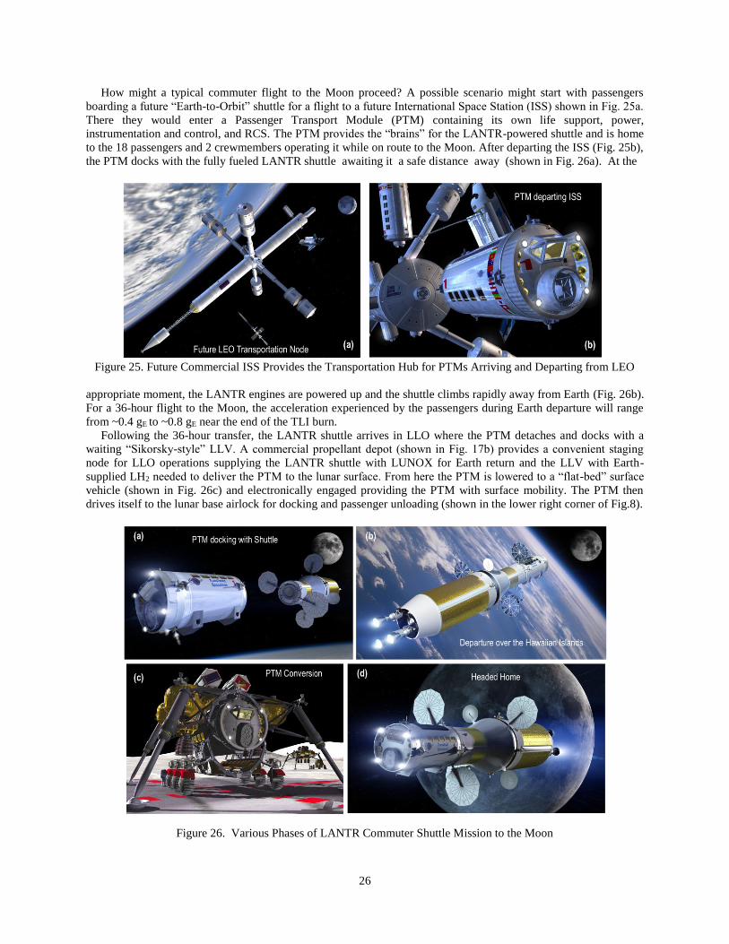
How might a typical commuter flight to the Moon proceed? A possible scenario might start with passengers
boarding a future “Earth-to-Orbit” shuttle for a flight to a future International Space Station (ISS) shown in Fig. 25a.
There they would enter a Passenger Transport Module (PTM) containing its own life support, power,
instrumentation and control, and RCS. The PTM provides the “brains” for the LANTR-powered shuttle and is home
to the 18 passengers and 2 crewmembers operating it while on route to the Moon. After departing the ISS (Fig. 25b),
the PTM docks with the fully fueled LANTR shuttle awaiting it a safe distance away (shown in Fig. 26a). At the
Figure 25. Future Commercial ISS Provides the Transportation Hub for PTMs Arriving and Departing from LEO
appropriate moment, the LANTR engines are powered up and the shuttle climbs rapidly away from Earth (Fig. 26b).
For a 36-hour flight to the Moon, the acceleration experienced by the passengers during Earth departure will range
from ~0.4 gE to ~0.8 gE near the end of the TLI burn.
Following the 36-hour transfer, the LANTR shuttle arrives in LLO where the PTM detaches and docks with a
waiting “Sikorsky-style” LLV. A commercial propellant depot (shown in Fig. 17b) provides a convenient staging
node for LLO operations supplying the LANTR shuttle with LUNOX for Earth return and the LLV with Earth-
supplied LH2 needed to deliver the PTM to the lunar surface. From here the PTM is lowered to a “flat-bed” surface
vehicle (shown in Fig. 26c) and electronically engaged providing the PTM with surface mobility. The PTM then
drives itself to the lunar base airlock for docking and passenger unloading (shown in the lower right corner of Fig.8).
Figure 26. Various Phases of LANTR Commuter Shuttle Mission to the Moon
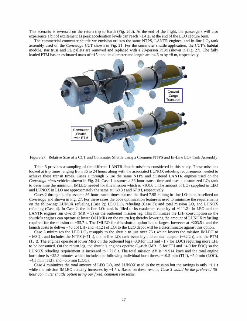
27
This scenario is reversed on the return trip to Earth (Fig. 26d). At the end of the flight, the passengers will also
experience a bit of excitement as peak acceleration levels can reach ~1.4 gE at the end of the LEO capture burn.
The commercial commuter shuttle we envision utilizes the same NTPS, LANTR engines, and in-line LO2 tank
assembly used on the Conestoga CCT shown in Fig. 21. For the commuter shuttle application, the CCT’s habitat
module, star truss and PL pallets are removed and replaced with a 20-person PTM (shown in Fig. 27). The fully
loaded PTM has an estimated mass of ~15 t and its diameter and length are ~4.6 m by ~8 m, respectively.
Figure 27. Relative Size of a CCT and Commuter Shuttle using a Common NTPS and In-Line LO2 Tank Assembly
Table 5 provides a sampling of the different LANTR shuttle missions considered in this study. These missions
looked at trip times ranging from 36 to 24 hours along with the associated LUNOX refueling requirements needed to
achieve these transit times. Cases 1 through 5 use the same NTPS and clustered LANTR engines used on the
Conestoga-class vehicles shown in Fig. 24. Case 1 assumes a 36-hour transit time and uses a customized LO2 tank
to determine the minimum IMLEO needed for this mission which is ~160.6 t. The amount of LO2 supplied in LEO
and LUNOX in LLO are approximately the same at ~69.3 t and 67.9 t, respectively.
Cases 2 through 4 also assume 36-hour transit times but use the fixed 7.95 m long in-line LO2 tank baselined on
Conestoga and shown in Fig. 27. For these cases the code optimization feature is used to minimize the requirements
on the following: LUNOX refueling (Case 2); LEO LO2 refueling (Case 3); and total mission LO2 and LUNOX
refueling (Case 4). In Case 2, the in-line LO2 tank is filled to its maximum capacity of ~111.2 t in LEO and the
LANTR engines run O2-rich (MR = 5) on the outbound mission leg. This minimizes the LH2 consumption so the
shuttle’s engines can operate at lower O/H MRs on the return leg thereby lowering the amount of LUNOX refueling
required for the mission to ~55.7 t. The IMLEO for this shuttle option is the largest however at ~203.5 t and the
launch costs to deliver ~40 t of LH2 and ~112 t of LO2 to the LEO depot will be a discriminator against this option.
Case 3 minimizes the LEO LO2 resupply to the shuttle to just over 76 t which lowers the mission IMLEO to
~168.2 t and includes the NTPS (~71 t), the in-line LO2 tank assembly and conical adaptor (~82.2 t), and the PTM
(15 t). The engines operate at lower MRs on the outbound leg (~3.9 for TLI and ~1.7 for LOC) requiring more LH2
to be consumed. On the return leg, the shuttle’s engines operate O2-rich (MR ~5 for TEI and ~4.9 for EOC) so the
LUNOX refueling requirement is increased to ~72.8 t. The total mission V is ~9.914 km/s and the total engine
burn time is ~25.3 minutes which includes the following individual burn times: ~10.5 min (TLI), ~5.0 min (LOC),
~4.3 min (TEI), and ~5.5 min (EOC).
Case 4 minimizes the total amount of LEO LO2 and LUNOX used in the mission but the savings is only ~1.1 t
while the mission IMLEO actually increases by ~1.5 t. Based on these results, Case 3 would be the preferred 36-
hour commuter shuttle option using our fixed, common size tanks.

28
Table 5. LANTR Commuter Shuttle Mission Options, V Budgets, and LUNOX Refueling Needs
Case 5 focuses on achieving the fastest transit times possible by taking full advantage of the extra propellant
capacity that exists in the vehicle’s in-line LO2 tank. By increasing the commuter shuttle’s LO2 loading to its
maximum capacity of ~111.2 t before TLI, refueling with ~80.4 t of LUNOX before TEI, and operating the LANTR
engines O2-rich (MR = 5) out and back, the shuttle can decrease its 1-way transit time from 36 to 32.8 hours. The
additional LO2 loading prior to TLI increases the required IMLEO to ~203.3 t which includes the NTPS (~71 t), the
in-line LO2 tank assembly and adaptor section (~117.3 t), and the PTM (15 t). The decreased transit time increases
the total mission V by ~0.567 km/s to ~10.5 km/s. The total mission burn time is ~25.3 minutes and the individual
burn times are ~11 min (TLI), ~3.5 min (LOC), ~5.1 min (TEI), and ~5.7 min (EOC).
Case 6 is similar to 5 with the exception that it uses only two LANTR engines thereby decreasing the dry mass of
the NTPS by ~5.5 t – the mass of the engine, its external radiation shield and thrust vector control system. By
reducing the NTPS mass, the shuttle’s transit times can be shortened even further – down to ~30.3 hours. For this
case, the shuttle is resupplied with ~111.2 t of LO2 before TLI, refuels with ~79 t of LUNOX before TEI, and its
engines operate O2-rich out and back. The IMLEO for this case is ~197.8 t which includes the NTPS (~65.5 t), the
in-line LO2 tank assembly and adaptor section (~117.3 t), and the PTM (15 t). The decreased transit time increases
the total mission V by an additional ~0.626 km/s to ~11.1 km/s including the increased g-losses from using only
two engines. With the available LH2 and one less engine, the maximum mission burn time increases to ~37.9
minutes with individual burn durations of ~16.5 min (TLI), ~5.6 min (LOC), ~8 min (TEI), and ~7.8 min (EOC).
Case 7 is similar to 6 except that it uses some of the ELH2 delivered to the LLO depot by NTR tankers to “top
off” the shuttle’s LH2 tank before returning to Earth. By resupplying the shuttle with ~111.2 t of LO2 before TLI,
refueling it with ~105.7 t of LO2 and ~12.2 t of LH2 before TEI, and operating O2-rich on the way back to Earth, the
24-hour trip to the Moon taken by Dr. Floyd in 2001 becomes a possibility. The IMLEO for this case is ~198 t
including the NTPS (~65.5 t), the in-line LO2 tank assembly and adaptor section (~117.4 t), and the PTM (15 t). The
total V required for this rapid shuttle capability to the Moon is ~13.1 km/s including g-losses. With additional LH2
supplied to the NTPS and only two engines, the maximum mission burn time is now ~49.7 minutes with burn times
of ~18.2 min (TLI), ~10.3 min (LOC), ~12.5 min (TEI), and ~8.7 min (EOC). Although faster, Case 7 has a number
of negative features when compared to Case 3: (1) it is heavier; (2) requires more LUNOX refueling; (3) has a larger
total V; and (4) total burn time requirement; and (5) has a less robust “engine-out” capability with only 2 engines.

29
Alternating Outbound and Return PTM and Priority Cargo Deliveries on the same Shuttle Flight
In addition to a commercial shuttle service for passengers, it is also likely that similar services will be developed
for delivering high priority cargo. Today, on their website for international shipping [44], UPS advertizes that they
“...ship more packages to more places than any other carrier.” They go on to say that “whether you're shipping
packages or pallets, importing or exporting, our extensive transportation and logistics network can get your
shipments where they need to be, when they need to be there.” Similarly, with a membership in Amazon Prime [45],
the company promises free two-day shipping on your purchases.
In this section, we examine the performance impact of alternating outbound and return deliveries of a PTM and
priority cargo shipment on the same shuttle flight. The shipping container we envision has a gross mass of ~7.5 t and
carries ~5 t of cargo within its pressurized volume. The container is scaled from the Cygnus spacecraft, developed
by Orbital ATK. Cygnus is an automated cargo vehicle [46] designed to transport supplies to the International Space
Station. It has a dry mass of ~5 t and can carry up to 3.5 t of cargo in its pressurized cargo module. An attached
service module, provides auxiliary propulsion and up to 4 kWe of electrical power using two PVAs [46].
The Priority Cargo Container (PCC) used in this analysis draws its electrical power from the twin PVAs located
at the front end of the shuttle’s in-line LO2 tank assembly (shown in Fig. 28). We also assume it has the same outer
mold line as the PTM. An example of this alternating payload delivery scenario is shown in Fig. 29 which depicts a
Next Day Delivery (NDD) priority cargo flight departing LEO on its way to the Moon. After it arrives, the PCC
detaches and docks with the Sikorsky-style LLV for delivery to the lunar surface in the same manner as the PTM.
The shuttle’s in-line LO2 tank would then be refueled at the LLO depot in preparation for an arriving PTM from the
surface and its return trip to Earth. On the next flight, a PTM would depart LEO for the Moon and the PCC would be
returned.
Figure 28. Priority Cargo Delivery Vehicle using LANTR Shuttle System
Figure 29. Alternating PCC and PTM Payloads to the Moon and Back on the same Shuttle Flight

30
Table 6. Alternating PTM–PCC Mission Options, Trip Times Possibilities, and LUNOX Refueling Needs
Table 6 provides a sampling of two different sets of alternating PTM–PCC mission options considered in this
study. In the first set of PTM–PCC delivery missions (Cases 1 and 2), the 3-engine NTPS and fixed length in-line
LO2 tank are used and the transit times out and back are 36 hours. In Case 1, the PTM is delivered on the outbound
leg followed by the PCC on the return leg. Approximately 66 t of LEO LO2 is supplied to the shuttle prior to TLI
and it is refueled in LLO with ~55.1 t of LUNOX prior to TEI. The IMLEO for this mission is ~157.6 t consisting of
the NTPS (~70.8 t), the in-line LO2 assembly and adaptor section (~71.8 t) and the PTM (15 t). The total mission
V is ~9.910 km/s and the total engine burn time is again ~25.3 minutes for the 3-engine NTPS and its available
LH2 propellant loading.
In Case 2, the mission scenario is reversed with the PCC being delivered on the outbound leg followed by the
PTM on the return leg. The shuttle is supplied with ~62.2 t of LEO LO2 prior to TLI and is refueled with ~64.8 t of
LUNOX prior to TEI. The IMLEO for this mission is ~146.5 t consisting of the NTPS (~70.9 t), the in-line LO2
assembly and adaptor section (~68.1 t) and the PCC (7.5 t). The total mission V and engine burn time are nearly
identical to Case 1 at ~9.909 km/s and ~25.3 minutes. The slightly lower total V for Case 2 is attributed to the
PCC’s smaller mass resulting in lower g-losses during the TLI burn.
In the second set of PTM–PCC delivery missions (Cases 3 and 4), we continue using the same in-line LO2 tank
but the NTPS now uses only 2 LANTR engines. We also set the transit times for PTM delivery at 24 hours and for
the PCC delivery at 48 hours. Like Case 1, Case 3 delivers the PTM on the outbound leg followed by the PCC on
the return leg. Because of the faster transit time used on the PTM mission leg, ~105.3 t of LO2 must be supplied to
the shuttle prior to TLI. Similarly, the LUNOX refueling requirement needed is reduced to ~44.7 t because of the
PCC’s smaller mass and extended transit time for the return to Earth. The IMLEO for this mission is ~191.2 t which
includes the NTPS (~65.2 t), the in-line LO2 assembly and adaptor section (~110 t) and the PTM (15 t). The total
mission V is ~10.959 km/s and the total engine burn time increases to ~37.8 minutes. The burn times for the
individual maneuvers are ~17.9 min (TLI), ~10.8 min (LOC), ~3.2 min (TEI), and ~5.9 min (EOC).
In Case 4, the mission scenario is again reversed with the PCC being delivered on the outbound leg followed by
the PTM on the return leg. The amount of LEO LO2 now supplied to the shuttle is reduced by ~63% to ~65.9 t.
Similarly, the LUNOX refueling required to return the heavier PTM back to Earth in 24 hours more than doubles to
~93.2 t. The IMLEO for this mission is ~144.7 t consisting of the NTPS (~65.4 t), the in-line LO2 assembly and
adaptor section (~71.8 t) and the PCC (7.5 t). Again, the total mission V and engine burn time are nearly identical
to Case 3 at ~10.951 km/s and ~37.9 minutes. However, in Case 4, the durations of the outbound and inbound burns
are reversed at ~12.5 min (TLI), ~3.7 min (LOC), ~11.6 min (TEI), and ~10.2 min (EOC).
In all of the above cases, the code’s optimizer routine looks for a solution that allows the mission to be executed
with the minimum amount of LO2 (i.e., the total of the initial LEO LO2 and the refuel LUNOX supplied to the
vehicle). It achieves this goal by manipulating the LO2 amounts and the MR values until it finds the solution with the
minimum total LO2. The RCS requirements between major propulsive maneuvers are also adjusted and determined
in the process.

31
IX. Mining and Processing Requirements and Estimated LUNOX Reserves
To get a better idea on what the mining and processing requirements are to support the kinds of missions
discussed in this paper, we selected the 3-engine LANTR commuter shuttle mission (Case 5 in Table 5) that runs
O2-rich (MR = 5, Isp = 516 s) out to the Moon back, and has 1-way transit times of ~32.8 hours. The LUNOX
refueling requirement for this mission is ~80.5 t and the total mission burn time on each of the LANTR engines is
~25 minutes. Assuming a 10 hour “full-power” lifetime on the engine fuel, a typical LANTR shuttle could perform
~24 missions. Assuming a 5-ship fleet and weekly trips to the Moon, each LANTR shuttle would make around 10 to
11 flights per year resulting in a service life of ~2.2 years. Near the end of life, the shuttle’s NTPS would be used to
inject cargo missions to various destinations before being disposed of in heliocentric space.
To support weekly commuter flights to the Moon will require annual LUNOX production levels of ~12,540 t/yr
(see Table 7). Approximately 4,190 t of LUNOX is used by the LANTR shuttle, ~6,140 t by four second generation
Sikorsky-style LUNOX tanker LLVs (see Fig. 30) flying one resupply mission to the LLO depot each week over the
course of a year, and ~2,220 t used by the same Sikorsky-style LLVs to transport arriving and departing PTMs to
and from the LS. Each LLV has a dry mass of ~10.9 t and a maximum LH2/LO2 propellant capacity of ~35 t.
A preliminary assessment of plant mass, power level, feedstock throughput, and required mining area has been
made assuming a LUNOX operation employing thirteen modular units each with a production capacity of 1000 t/yr.
Table 8 compares the characteristics for two LUNOX plants – one based on hydrogen reduction of ilmenite [30],
and the other on “iron-rich” volcanic glass feedstock. The advantages of using volcanic glass feedstock are apparent
and show mass and power requirements that are 43% and 50% lower than that of an ilmenite reduction plant using a
soil feedstock. Included in the volcanic glass reduction plant mass of ~105.3 t is the mining (~9.6 t) and processing
equipment (84.6 t) – both of which include a 30% DWC – plus the fission reactor power source (~11.1 t). The plant
power requirement of ~1.52 MWe includes ~10.7 kWe for the mining equipment and ~1509 kWe for the processing
equipment. Both values again include a 30% margin. The process power dominates and is a function of the LUNOX
production rate and is primarily associated with the electric heaters, electrolysis cell and the oxygen liquifiers as
discussed in Sect. II and pointed out in Fig. 5.
Using the “low end” 4% O2 yield obtained from orange and black volcanic glass beads still translates into more
than an order of magnitude reduction in the amount of mined material. The mining equipment used at each 1000 t/yr
production plant consists of two front-end loaders and four haulers. To produce ~13,000 t of LUNOX annually will
require a glass throughput of ~3.25 x 10⁵ t/yr and a soil mining rate at each production plant of just under 6 t per
hour per loader assuming the same 35% mining duty cycle used in the ilmenite processing plant results. This duty
cycle corresponds to mining operations during ~70% of the available lunar daylight hours (~3066 hours per year).
While this number is large, it is modest compared to terrestrial coal and proposed lunar helium-3 mining
activities. For example, with a single 1000 MWe coal-fired power plant consuming about sixty 100-ton train cars of
coal per day, the annual U.S. production rate for coal exceeds 500 million tons! Similarly, past proposals for mining
helium-3 on the Moon [47] to support a future fusion-based power economy in the U.S. would require the
processing of ~2.8 billion tons of regolith to obtain the estimated 20 t of helium-3 needed annually (see Table 8).

32
Table 8. Comparison of Different Lunar Mining Concepts Showing
Plant Mass, Required Operating Power, and Mining Rates
Figure 31 shows our proposed site for a commercial LUNOX facility within the Taurus-Littrow DMD at the
southeastern edge of the Mare Serenitatis (~21°N, ~29.5°E) approximately 30 km west of the Apollo 17 landing site.
This deposit of largely black crystalline beads covers ~3000 km2 and is thought to be tens of meters thick. Assuming
an area of ~2000 km2 – equivalent to a square ~28 miles on a side, a mining depth of ~5 m and soil density
representative of the Apollo 17 volcanic glass (~1.8 g/cm3), and a MMR of 25 to 1 (equivalent to a 4% O2 yield),
Fig. 32 shows that the Taurus-Littrow DMD could produce ~720 million tons of LUNOX. Figure 32 also shows that
the mining areas needed to support commuter flights to the Moon are not unrealistic at ~0.036 km2 and ~0.18 km2
for 1 to 5 flights/week, respectively. Even at five times the higher ~65,000 t/year rate, there are sufficient LUNOX
resources at this one site to support ~25 commuter flights carrying 450 passengers each week for the next 2215 years
and more sites containing even larger quantities of iron-rich pyroclastic glass have been identified [24].
X. Summary, Concluding Remarks and a Look Ahead
The NTR offers significant benefits for lunar missions and can take advantage of the mission leverage provided
from using LDP – specifically LUNOX – by transitioning to LANTR propulsion. Using this enhanced version of
NTP has many advantages. It provides a variable thrust and Isp capability, shortens engine burn times, extends
engine life and allows combined LH2 and LO2 operation. Its use together with adequate supplies of LUNOX,
extracted from abundant reserves of FeO-rich volcanic glass, can lead to a robust nuclear LTS that evolves over time
and has unique mission capabilities. The examples we have discussed here include short transit time crewed cargo
transports, commuter shuttles and priority cargo delivery systems operating between transportation nodes /propellant
• Hydrogen Reduction of Ilmenite: (LUNOX Production @ 1000 t/year)
• Plant Mass (Mining, Beneficiation, Processing and Power) = 244 t
• Power Requirements (Mining, Beneficiation and Processing) = 3.0 MWe
• Regolith Throughput (assumes soil feedstock @ 7.5 wt% ilmenite
and mining mass ratio (MMR) of 327 t of soil per ton of LUNOX) = 3.3x10⁵ t/yr
• Hydrogen Reduction of “Iron-rich” Volcanic Glass: (LUNOX Production @ 1000 t/year)
• Plant Mass (Mining, Processing and Power) = 105 t
• Power Requirements (Mining and Processing) = 1.5 MWe
• Regolith Throughput (direct feed and processing of “iron-rich”
volcanic glass beads assuming a 4% O 2 yield and MMR = 25 to 1) = 2.5x10 4 t/yr
• Lunar Helium-3 Extraction: (5000 kg (5 t) He3/year)
• Mobile Miners (150 miners required, each weighing 18 t, = 2700 t
and each miner producing 33 kg He 3 per year)
• Power Requirements (200 kW direct solar power/miner) = 30.0 MW
• Regolith Throughput (processing and capture of Solar Wind
Implanted (SWI) volatiles occurs aboard the miner) = 7.1x10⁸ t/yr

33
Figure 31. Apollo 17 Site and Major Geographic Features of Taurus-Littrow Region
Figure 32. Required Mining Areas and LUNOX Production Rates to Support
Routine Commuter Flights to the Moon
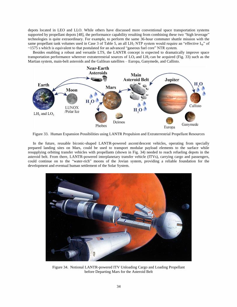
34
depots located in LEO and LLO. While others have discussed more conventional space transportation systems
supported by propellant depots [48], the performance capability resulting from combining these two “high leverage”
technologies is quite extraordinary. For example, to perform the same 36-hour commuter shuttle mission with the
same propellant tank volumes used in Case 3 of Table 5, an all LH2 NTP system would require an “effective Isp” of
~1575 s which is equivalent to that postulated for an advanced “gaseous fuel core” NTR system.
Besides enabling a robust and versatile LTS, the LANTR concept is expected to dramatically improve space
transportation performance wherever extraterrestrial sources of LO2 and LH2 can be acquired (Fig. 33) such as the
Martian system, main-belt asteroids and the Galilean satellites – Europa, Ganymede, and Callisto.
Figure 33. Human Expansion Possibilities using LANTR Propulsion and Extraterrestrial Propellant Resources
In the future, reusable biconic-shaped LANTR-powered ascent/descent vehicles, operating from specially
prepared landing sites on Mars, could be used to transport modular payload elements to the surface while
resupplying orbiting transfer vehicles with propellants (shown in Fig. 34) needed to reach refueling depots in the
asteroid belt. From there, LANTR-powered interplanetary transfer vehicle (ITVs), carrying cargo and passengers,
could continue on to the “water-rich” moons of the Jovian system, providing a reliable foundation for the
development and eventual human settlement of the Solar System.
Figure 34. Notional LANTR-powered ITV Unloading Cargo and Loading Propellant
before Departing Mars for the Asteroid Belt

35
In the nearer term, it is also possible that LANTR propulsion could find its way into NASA’s plans for a human
mission to Mars. This year is the seventh year in a row that NASA has been funding NTP research and development.
Preliminary development plans envision flight-testing a NTPS powered by three 25 klbf-class NTR engines
sometime in the late 2020’s. For the Mars mission, two additional tanks of LH2 – one an in-line tank and the other a
drop tank – are added to supplement that onboard the NTPS. Because of LH2’s low density, these additional tanks
increase the vehicle’s overall size and mass. By adding the afterburner feature to the NTPS and running the engines
at a MR ~1 during the LEO departure burn, the amount of LH2 used during this maneuver can be cut in half. The
thrust output of the NTPS is also increased by ~60% – from 75 klbf to over 120 klbf reducing gravity losses and
eliminating the need for multiple perigee burns during Earth departure. Afterwards the smaller LO2 drop tank can be
jettisoned and LH2 used for the rest of the mission.
This December marks the 45th anniversary of the Apollo 17 mission to Taurus-Littrow and unfortunately, the
termination of both the Apollo and the Rover/NERVA nuclear rocket programs. In the not-so-distant future, the
technological progeny from these two historic programs – LUNOX and LANTR – could allow the development of a
robust, reusable space transportation system that can be adapted to a wide variety of potential lunar missions using
the basic vehicle building blocks discussed in this paper.
The biggest challenge to making this vision a reality, however, will be the production of increasing amounts of
LDP and the development of propellant depots for vehicle refueling in LEO and LLO. An industry-operated,
privately-financed venture, with NASA as its initial customer, has frequently been mentioned as a possible blueprint
for how a commercial LUNOX operation and propellant depot might develop. With industry interested in
developing cislunar space and commerce, and competitive forces at work, the timeline for developing this capability
could well be accelerated beyond anything currently being envisioned. Only time will tell and maybe it will be
quicker than any of us can imagine.
Acknowledgments
The author (SKB) acknowledges the NTP Project, the Nuclear Power and Propulsion Technical Discipline Team
(NTDT), and Mark Klem (GRC Branch Chief) for their support of this work. Informative discussions with Carlton
Allen are also acknowledged. The author also expresses his thanks to two outstanding space artists – Bob Sauls
([email protected]) and Pat Rawlings ([email protected]) – whom he has had the pleasure of working with
over the course of his 29-year career at NASA. Their work has helped bring the vehicle designs and missions
developed and proposed by the author to life. The NASA-funded images produced by Pat include Figs. 1a-b, 4, 8,
17, 25, 26c, 30 and 34, and those by Bob include Figs. 1c-e, 12-16, 20-24, 26a, b and d, and 27-29.
References
[1] NASA’s Journey to Mars – Pioneering Next Steps in Space Exploration, National Aeronautics and Space
Administration, NP-2015-08-2018-HQ, Washington, DC, October 2015.
[2] Achenbach, J., “Trump, with NASA, has a new rocket and spaceship. Where’s he going to go?,” The Washington
Post, Health & Science, March 12, 2017; www.washingtonpost.com/national/health-science/trump-with-nasa...
[3] David, L., “Lunar Leap: Europe is Reaching for a Moon Base by the 2030s,” Space.com, December 30, 2015;
www.space.com/31488-european-moon-base-2030s.html.
[4] Aliberti, M., When China Goes to the Moon, ESPI, Springer Wien, New York, 2015.
[5] Zolfagharifard, E., and Gray, R., “Russia to Conquer the Moon in 2030: Country says it's planning a permanent
manned base on the lunar surface,” Daily Mail, December 3, 2015; www.dailymail.co.uk/sciencetech/article-
3344818/Russia.
[6] Chang, K., “SpaceX Plans to Send 2 Tourists Around the Moon in 2018,” The New York Times, Science,
February 27, 2017; www.nytimes.com/2017/02/27/science/spacex-moon-tourists.html.
[7] Malik, T., “Private Space Stations Could Orbit the Moon by 2020, Robert Bigelow says,” Space.com, March 9,
2017; www.space.com/35978-private-moon-refueling-station-by-2020.html.
[8] Wall, M., “Mining the Moon’s Water: Q&A with Shackleton Energy’s Bill Stone,” Space.com, January 13,
2015; www.space.com/10619-minimg-moon-water-bill-stone-110114.html.
[9] David, L., “Inside ULA’s Plan to Have 1,000 People Working in Space by 2045,” Space.com, June 29, 2016;
www.space.com/33297-satellite-refueling-business-proposal-ula.html.
[10] Davenport, C., “An exclusive look at Jeff Bezos’s plan to set up Amazon-like delivery for ‘future human
settlement’ of the moon,” The Washington Post, The Switch, March 2, 2017; www.washingtonpost.com/news/the-
switch//wp/2017/03/02/an-exclusive…

36
[11] Sullivan, T. S., and McKay, D. S., Using Space Resources, NASA Johnson Space Center, pp. 4, 1991.
[12] Allen, C. C., Morris, R. V., and McKay, D. S., “Experimental Reduction of Lunar Mare Soil and Volcanic
Glass,” Journal of Geophysical Research, 99, pp. 23,173-23,185, November 1994.
[13] http://nssdc.gsfc.nasa.gov/planetary/ice/ice_moon.html, “Ice on the Moon - A Summary of Clementine and
Lunar Prospector Results,” December 10, 2012.
[14] Borowski, S. K., “The Rationale/Benefits of Nuclear Thermal Rocket Propulsion for NASA’s Lunar Space
Transportation System,” AIAA-91-2052, June 1991 (also NASA TM – 106730).
[15] Borowski, S. K., and Alexander, S. W., “Fast Track NTR Systems Assessment for NASA’s First Lunar Outpost
Scenario,” AIAA-92-3812, July 1992 (also NASA TM – 106748).
[16] Borowski, S. K., McCurdy, D. R., and Burke. L. M., “The Nuclear Thermal Propulsion Stage (NTPS): A Key
Space Asset for Human Exploration and Commercial Missions to the Moon,” AIAA–2013-5465, September 2013
(also NASA/TM–2014-218105).
[17] Borowski, S. K., et al., “Affordable Development and Demonstration of a Small Nuclear Thermal Rocket
(NTR) Engine and Stage: How Small is Big Enough?,” AIAA–2015-4524, August 31–September 2, 2015 (also
NASA/TM–2016-219402).
[18] Borowski, S. K., and Dudzinski. L. A., “2001: A Space Odyssey Revisited – The Feasibility of 24 Hour
Commuter Flights to the Moon Using NTR Propulsion with LUNOX Afterburners,” AIAA–97-2956, July 1997
(also NASA/TM–1998-208830/REV2).
[19] Joyner, C. R., et al., “TRITON: A Trimodal capable, Thrust Optimized Nuclear Propulsion and Power System
for Advanced Space Missions,” AIAA–2004-3863, July 2004.
[20] Bulman, M. J., et al., “LANTR Engine System Integration,” AIAA–2004-3864, July 2004.
[21] Allen, C. C., and McKay, D. S., “Lunar Oxygen Production -- Ground Truth and Remote Sensing,” AIAA 95-
2792, July 1995.
[22] Allen, C. C., Morris, R. V., and McKay, D. S., “Oxygen Extraction from Lunar Soils and Pyroclastic Glass,”
Journal of Geophysical Research, 101, pp. 26,085-26,095, November 1996.
[23] Hawke, B. R., Coombs, C. R., and Clark, B., “Ilmenite-rich Pyroclastic Deposits: An Ideal Lunar Resource,” in
proceedings of 20th Lunar and Planetary Science Conference, Houston, pp. 249-258, 1990.
[24] Gaddis, L. R., et al., “Compositional analyses of lunar pyroclastic deposits,” Icarus, 161, pp. 262-280, 2003.
[25] Spudis, P. D., and Lavoie, A. R., “Using the resources of the Moon to create a permanent, cislunar space faring
system,” AIAA–2011-7185, September 2011.
[26] Haruyama, J., et al., “Lack of Exposed Ice Inside Lunar South Pole Shackleton Crater,” Science, 322, pp. 938-
939, November 7, 2008.
[27] Davis, H. P., “Lunar Oxygen Impact upon STS Effectiveness,” Eagle Engineering Report No. 8363, Eagle
Engineering, Inc., Houston, Texas, May 1983.
[28] Frisbee, R. H., and Jones, R. M., “An Analysis of Propulsion Options for Transport of Lunar Materials to Earth
Orbit,” AIAA–83-1344, June 1983.
[29] Taylor, L. A., and Carrier, W. D., “Oxygen Production on the Moon: An Overview and Evaluation,” in
Resources of Near Earth Space, eds. Lewis, J., Matthews, M. S., and Guerrieri, M. L., Tuscon University Press, pp.
69-108, 1993.
[30] Christiansen, E. L., et al., “Conceptual Design of a Lunar Oxygen Pilot Plant,” EEI Report No. 88-182, Eagle
Engineering, Inc., Houston, TX, July 1988.
[31] Gibson, M. A., and Knudsen, C. W., “Lunar Oxygen Production from Ilmenite,” in Lunar Bases and Space
Activities of the 21st Century, ed. Mendell, W. W., Lunar and Planetary Institute, Houston, pp. 543-550, 1985.
[32] Allen, C. C., Weitz, C. M., and McKay, D. S., “Prospecting for Lunar Oxygen with Gamma Ray Spectrometry
and Multispectral Imaging,” in Workshop on New Views of the Moon: Integrated Remotely Sensed, Geophysical,
and Sample Datasets, eds. Jolliff, B. L., and Ryder, G., LPI Contribution No. 958, Lunar and Planetary Institute,
Houston, pp. 19-20, 1998.
[33] Feldman, W. C., et al., Lunar Planet, Sci. XXVII, pp. 355-356, 1996.
[34] Lucey, P. G., Taylor, G. J., and Malaret, E., “Abundance and Distribution of Iron on the Moon,” Science, 268,
pp. 1150-1153, May 26, 1995.
[35] Koeing, D. R., “Experience Gained from the Space Nuclear Rocket Programs (Rover/NERVA),” Los Alamos
National Laboratory, Report LA-10062-H, Los Alamos, NM, May 1986.
[36] Bulman, M. J., and Neill, T. M., “Simulated LOX-Augmented Nuclear Thermal Rocket (LANTR) Testing,”
AIAA–2000-3897, July 2000.
[37] https://en.wikipedia.org/wiki/RL10.
37
[38] Hodge, J., et al., “Space Transfer Vehicle – Lunar Transportation Ground Based LEO Rendezvous & Docking
Study”, NAS8-37856, Martin Marietta, August 1991.
[39] http://www.history.com/topics/conestoga-wagon.
[40] Courtesy of the Landis Valley Village & Farm Museum, Pennsylvania Historical and Museum Commission.
[41] Ryan, S. W., and Borowski, S. K., “Integrated System Modeling for Nuclear Thermal Propulsion,” AIAA–
2014-3624, July 2014.
[42] 2001: A Space Odyssey, produced and directed by S. Kubrick, screenplay by S. Kubrick and A. C. Clarke, a
Metro-Goldwyn-Mayer (MGM) film released 1968.
[43] Clarke, A. C., 2001: A Space Odyssey, based on a screenplay by S. Kubrick an A. C. Clarke, a Signet Book,
published by The New American Library, Inc., July 1968, p. 61.
[44] https://global.ups.com.
[45] https://www.amazon.com/Amazon-Prime.
[46] https://en.wikipedia.org/wiki/Cygnus_(spacecraft).
[47] Sviatoslavsky, I. V., “Processing and Energy Costs for Mining Lunar Helium-3,” in Workshop Proc. on Lunar
Helium-3 and Fusion Power,” NASA CP-10018, pp. 129-146, 1988.
[48] Smitherman, D., and Woodcock, G., “Space Transportation Infrastructure Supported by Propellant Depots,”
AIAA–2011-7160, September 2011.