load proportional safety brake michael j. cacciola boeing ... · michael j. cacciola boeing...
TRANSCRIPT

LOAD PROPORTIONAL SAFETY BRAKE
Michael J . C a c c i o l a
B o e i n g C o m m e r c i a l A i r p l a n e Company
INTRODUCTION
This brake i s a se l f - ene rg iz ing mechanical f r i c t i o n brake and is in- tended f o r u s e i n a r o t a r y d r i v e system. It inco rpora t e s a torque sensor which c u t s power t o t h e power u n i t on any overload condi t ion . The brake i s capable of d r i v i n g a g a i n s t an opposing load o r d r i v i n g , paying-out, an a id- i n g load i n e i t h e r d i r e c t i o n of r o t a t i o n . The brake a l s o acts as a no-back device when torque i s appl ied t o t h e output s h a f t .
The advantages of us ing t h i s type of device are:
1. Low f r i c t i o n a l d rag when d r i v i n g .
2. Smooth paying-out of an a i d i n g load wi th no runaway danger.
3 . Energy absorp t ion p ropor t iona l t o load.
4 . No-back a c t i v a t e s w i t h i n a few degrees of ou tput s h a f t r o t a t i o n and resets au tomat ica l ly .
5. Bu i l t - i n overload p ro tec t ion .
DESCRIPTION
Figure 1 shows a s e c t i o n view of t h e brake which is made up of two major components, t h e braking component and t h e torque sens ing component. The braking component i s comprised of t h r e e s e p a r a t e elements; t h e energi- z ing brake, t h e load sens ing cams, and t h e holding brake. The torque sensor i s comprised of load sens ing d e t e n t s , load r e a c t i n g sp r ings and a swi tch assembly. The brake absorbs energy i n propor t ion t o t h e load and d i s s i p a t e s t h e energy as hea t through an o i l f i l l e d , f inned aluminum housing.
F igure 2 shows t h e brake assembly without t h e torque sens ing element a t t ached . r e q u i r e overload p ro tec t ion .
This type of brake can be used i n a p p l i c a t i o n s which do not
The inpu t s h a f t (1) has one ou te r and one inne r set of d r i v i n g s l o t s , see Figures 1 and 3. s h a f t (2) and provide a s t r a i g h t through d r i v e . They a l s o provide a second- a r y load pa th i n case of brake f a i l u r e . The o u t e r d r i v i n g s l o t s con tac t l ugs on t h e sp r ing cage (6) which i s index sp l ined t o t h e input c a m p l a t e (10). Th i s arrangement of d r i v i n g s l o t s and l u g s main ta ins alignment of t h e b a l l d e t e n t p o s i t i o n on t h e cam p l a t e s (10) (12) and keeps t h e hold ing brake de-energized.
The inner set of s l o t s con tac t l ugs on t h e main brake
Because of t h e symmetry of t h e s e p a r t s , t h e brake w i l l
95
https://ntrs.nasa.gov/search.jsp?R=19790014377 2018-07-17T05:12:45+00:00Z
func t ion when d r iven i n e i t h e r d i r e c t i o n . Return s p r i n g s (33) provide an axial f o r c e t o t h e output cam p l a t e (12) which keeps t h e t h r e e b a l l s (11) sea t ed i n t h e i r d e t e n t p o s i t i o n and main ta ins a gap a t t h e brake p l a t e s t o e l imina te hold ing brake drag. t a i n e d i n t h e s p r i n g cage (6) provide a n axial f o r c e t o t h e energ iz ing brake which gene ra t e s a r e a c t i o n torque f o r energ iz ing t h e hold ing brake. The re- a c t i o n torque i s t r ansmi t t ed by t h e s t a t o r p l a t e s (9) which are grounded t o t h e e x t e r n a l housing (3) through s p l i n e t e e t h on t h e s t a t o r (37). Anti- f r i c t i o n t h r u s t bea r ings (5) (35) are used t o c a r r y t h e f o r c e of the energiz- i n g sp r ings (7) t o minimize f r i c t i o n a l drag developed by t h e relative r o t a t i o n of t h e inpu t c a m p l a t e (10) and main brake s h a f t (2) dur ing brake a p p l i c a t i o n . Nut (4) i s used t o react t h e energ iz ing sp r ing f o r c e and t o a d j u s t t h e gap a t t h e energ iz ing brake p l a t e s . The load sens ing element of t h e brake is made up of c i r c u l a r b a l l cams on both t h e inpu t and output cam p l a t e s (10) (12) , three b a l l s ( l l) , and a b a l l cage (36), see Figure 4 and 5. The b a l l cams are designed t o o p e r a t e i n e i t h e r d i r e c t i o n . forms a vee which h a s a r a d i u s smaller than t h e b a l l r ad ius . Th i s provides a d e t e n t e f f e c t which prevents movement u n t i l t h e t r ansmi t t ed torque a c t u a t e s t h e c a m p l a t e s . l a r g e r than t h e b a l l r ad ius . This a l lows t h e b a l l s t o seek a p o s i t i o n where a l l t h e b a l l s share t h e load , and compensates f o r t o l e r a n c e s on t h e ind iv id- u a l p a r t s . The b a l l cage (36) i s used t o cap tu re t h e t h r e e b a l l s and f o r c e s t h e b a l l s t o move i n unison up t h e cam su r faces . The brake p l a t e s (8) (13) are a s p e c i a l des ign which have a con t ro l l ed uniform c o e f f i c i e n t of f r i c t i o n . The f r i c t i o n l i n i n g i s non-metall ic and is bonded t o a steel co re which i s sp l ined t o t h e cam p l a t e s . The s t a t o r p l a t e s (9) (14) have an e x t e r n a l s p l i n e wi th every o t h e r t o o t h removed, see Figure 3, and provide t h e mating s u r f a c e f o r t h e brake p l a t e s (8) (13) . The s t a t o r (37) a l s o has every o t h e r t o o t h removed on t h e i n t e r n a l s p l i n e i n t h e area of t h e holding brake only. Spacers (15) are provided i n both t h e energ iz ing and hold ing brake t o change t h e braking c a p a c i t y depending on t h e load. The load s p r i n g s (34) are re- t a ined i n s p r i n g cage (16). brake i n d i r e c t p ropor t ion t o t h e load . The sp r ings are s e l e c t e d so t h a t t h e f o r c e generated by t h e load sens ing cams i s w i t h i n t h e i r working range. Th i s enhances t h e smoothness of t h e brake when d r i v i n g an a id ing load . Shim (32) i s a laminated shim used t o a d j u s t the gap on t h e holding brake. (18) is used t o l o c k t h e p re s su re p l a t e (17) t o t h e main brake s h a f t (2) f o r r e a c t i n g t h e load s p r i n g fo rce . d e t e n t s h a f t which r e t a i n t h r e e b a l l s (20) i n countersunk d e t e n t s . The inpu t d e t e n t s h a f t (19) i s s p l i n e d t o t h e main brake s h a f t (2) and t r a n s f e r s l oad t o t h e output d e t e n t s h a f t (31) through t h e t h r e e b a l l s (20). I n case of b a l l d i s i n t e g r a t i o n , a secondary load pa th i s provided through a p a i r of d r i v i n g l u g s w i t h enlarged c l ea rances t o a l low normal opera t ion . d e t e n t s h a f t (31) is sp l ined t o t h e output s h a f t (26) and has a f l a n g e which, when d isp laced , c o n t a c t s a n a n t i - f r i c t i o n bear ing (22) on t h e swi tch assembly. F ive b e l l e v i l l e s p r i n g s (30) provide the f o r c e t o t h e output d e t e n t s h a f t f o r r e t a i n i n g t h r e e b a l l s (20) i n t h e d e t e n t s . The sp r ing f o r c e is reac t ed t o t h e inpu t d e t e n t s h a f t through washers (28) , a n a n t i - f r i c t i o n t h r u s t bear ing (29) , and nu t (27). A lever (24) and s h a f t (23) are used t o t r a n s f e r t h e d e t e n t s h a f t motion t o a c t u a t e t h e swi tch (21). An a d j u s t a b l e s t o p (25) is provided f o r t h e lever (24) t o main ta in a c l ea rance gap a t a n t i - f r i c t i o n bea r ing (22) dur ing normal opera t ion .
The energ iz ing sp r ings (7) which are re-
The cam s l o p e
Transverse t o t h e d i r e c t i o n of r o t a t i o n t h e cam r a d i u s is
They supply an a x i a l f o r c e t o t h e hold ing
Nut
The torque sensor has an inpu t and output
The output
96

PRINCIPLES OF OPERATION
Driving Against A Load (Figure 6)
When d r i v i n g from a stopped p o s i t i o n wi th t h e brake f u l l y energized, (no-back a c t i v a t e d ) t h e i n i t i a l r o t a t i o n of t h e inpu t s h a f t (1) releases t h e holding brake. The inpu t s h a f t (1) s u p p l i e s to rque d i r e c t l y t o t h e main brake s h a f t (2) through a p a i r of d r i v i n g lugs , see Figure 3. The output cam p l a t e (12) i s d r iven by t h e main brake s h a f t (2) t o a l i g n t h e b a l l d e t e n t s . The holding brake a l lows t h e cam p l a t e (12) t o r o t a t e because of t h e enlarged c l ea rance between t h e s t a t o r p l a t e (14) and t h e s t a t o r (37) s p l i n e t e e t h . The input s h a f t (1) s imultaneously d r i v e s t h e s p r i n g cage (6) through another p a i r of d r i v i n g l u g s which provide torque t o t h e inpu t cam p l a t e (10) t o overcome t h e energ iz ing brake torque. The cam p l a t e s are keyed so t h a t t h e b a l l d e t e n t s are a l igned when t h e d r i v i n g f a c e s of both sets of l ugs are i n con tac t . With t h e b a l l d e t e n t s a l igned t h e r e t u r n s p r i n g s (33) provide a n a x i a l f o r c e t o t h e output c a m p l a t e (12) which keeps t h e t h r e e b a l l s ( l 1 ) s ea t ed i n t h e d e t e n t s . Since t h e t h r e e b a l l s (11) cannot r ise up t h e cam s u r f a c e s t h e brake remains de-energized. Torque is then app l i ed through a s p l i n e t o t h e input d e t e n t s h a f t (19) of t h e torque sensor and t r a n s f e r r e d through t h r e e b a l l s (20) t o t h e d e t e n t s h a f t (31). The output d e t e n t s h a f t (31) i s coupled t o t h e output s h a f t (26) through a s p l l n e and t r a n s m i t s t h e torque t o t h e d r i v e system. When an overload cond i t ion i s developed t h e load r e a c t i n g s p r i n g s (30) are not supplying enough f o r c e t o keep t h e t h r e e b a l l s (20) s ea t ed i n t h e d e t e n t s . The output d e t e n t s h a f t (31) i s then d isp laced a x i a l l y t o ope ra t e a l e v e r (24) which t r i p s t h e swi tch (21) i n t h e e l e c t r i c a l c o n t r o l c i r c u i t and c u t s power t o t h e d r i v e motor.
Stopped-No-Back (Figure 7 )
When t h e d r i v e motor i s s topped, t h e load back d r i v e s t h e main brake s h a f t (2) and t h e output cam p l a t e (12). The energ iz ing sp r ings ( 7 ) main ta in a f o r c e on t h e energ iz ing brake p l a t e s which provide a r e a c t i o n torque t o t h e load through t h e t h r e e b a l l s (11) . A s to rque i s app l i ed , relative r o t a t i o n occurs between t h e inpu t cam p l a t e (10) and t h e output cam p l a t e (12) . This causes t h e output cam p l a t e (12) t o d i s p l a c e a x i a l l y as t h e t h r e e b a l l s (11) r i se up t h e cam s u r f a c e s and remove t h e holding brake p l a t e c learance . Fur ther i nc rease i n back d r i v i n g torque d i s p l a c e s t h e output cam p l a t e (12) t o compress t h e load s p r i n g s (34) t o some f o r c e l e v e l . When t h e s p r i n g f o r c e appl ied t o t h e holding brake p l a t e s (13) (14) gene ra t e s s u f f i c i e n t to rque a l l movement s t o p s and t h e load i s f u l l y r eac t ed .
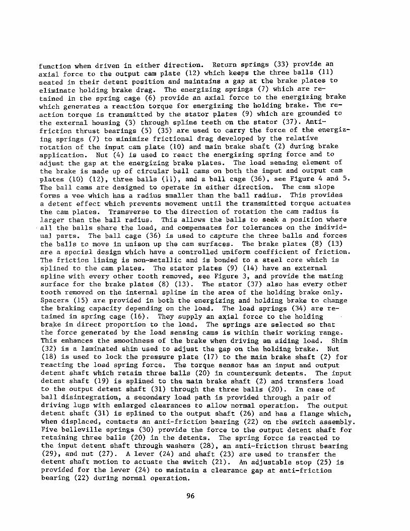
Driving An Aiding Load - Paying Out (Figure 8)
When d r i v i n g a n a i d i n g load , t h e inpu t s h a f t (1) r o t a t e s i n t h e d i r ec - t i o n of t h e load and t h e o u t e r set of d r i v i n g l u g s con tac t t h e sp r ing cage (6) which a p p l i e s to rque t o t h e input c a m p l a t e ( l o ) , see Figure 3. When t h i s to rque exceeds t h e d i f f e r e n c e between t h e energ iz ing brake torque and t h e r e a c t i o n torque of t h e t h r e e b a l l s (111, t h e main brake s h a f t (2) r o t a t e s under t h e in f luence of t h e load . The load sp r ings (34) modulate t h e f o r c e of t h e load sens ing cams on t h e holding brake p l a t e s (13) (14) which gene ra t e a holding torque pe rmi t t i ng t h e load t o pay out smoothly a t d r i v e motor speed.
97

SYMBOLS
- Input Torque To - Drag Torque TM = Torque Across B a l l FE = Modulating Spring Force FR = Axial Force A t B a l l Ft = Coeff ic ien t Of F r i c t i o n r D = Main Brake P l a t e Radius r g = Number Of Drag Brake Surfaces nM = Cam Slope Angle
Output Torque Main Brake Torque Energizing Spring Force Return Spring Force Tangent ia l Force A t B a l l Drag Brake P l a t e Radius Radius To B a l l Number Of Main Brake Surfaces
MAXIMUM CAM SLOPE ANGLE
For a given load t h e axial f o r c e on the b a l l is: (See Figure 7)
Minimum Holding Brake is:
Solut ion of t h e above equat ion reso lves i n t o a quadra t ic of t he form:
A tan02 + B tan0 - c = o Subs t i t u t ing values f o r a l l t h e known terms and so lv ing f o r 0 w i l l
g i v e the maximum cam s lope angle which w i l l hold t h e load without s l i pp ing .
BRAKE STABILITY
The brake as descr ibed i n Figures 1 and 2 is e a s i l y proportioned t o be self-energizing and capable of holding a load i n the s t a t i c o r stopped
98

condi t ion . smoothly without brake c h a t t e r . t h e brake i s r a p i d l y cyc l ing between locked-up and r e l eased .
The c r i t i c a l cond i t ion i s d r i v i n g o r paying ou t an a i d i n g load Chat te r i s an uns t ab le cond i t ion i n which
The fo l lowing i t e m s are requi red t o i n su re s t a b l e ope ra t ion of t h e brake:
1. F r i c t i o n material wi th a s t a b l e c o e f f i c i e n t of f r i c t i o n throughout t h e ope ra t ing range of temperature and brake p l a t e pressure .
2. Combination of f r i c t i o n material and o i l which minimizes t h e f l u c t u a t i o n between s t a t i c and dynamic c o e f f i c i e n t of f r i c t i o n .
3 . Correc t load ba lance between t h e ene rg iz ing brake and t h e main holding brake.
4 . Modulating sp r ing ra te t o balance maximum a x i a l load developed by t h e b a l l cams.
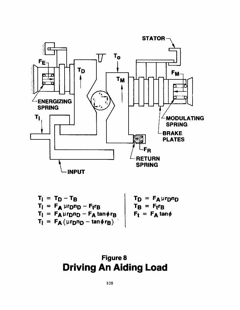
Another method of producing a s t a b l e brake is t o reduce t h e torque capac i ty of t h e energ iz ing brake t o a va lue below t h e b a l l to rque and then add a cons t an t drag brake t o t h e input s h a f t . The a f f e c t of reducing t h e energ iz ing brake i s t o make t h e brake r e v e r s i b l e , bu t t h e a d d i t i o n of t h e cons tan t d rag brake i n conjunct ion w i t h t h e o the r braking elements makes t h e brake i r r e v e r s i b l e and capable of r e a c t i n g t h e f u l l load. a n a i d i n g load , t h e inpu t to rque need only overcome t h e margin of t h e cons tan t drag brake which a l lows t h e load t o pay-out. F igure 9 shows a cons tan t drag brake app l i ed t o t h e inpu t s h a f t w i th a r a t c h e t i n g device which bypasses t h e brake when d r i v i n g a g a i n s t a load.
When d r i v i n g
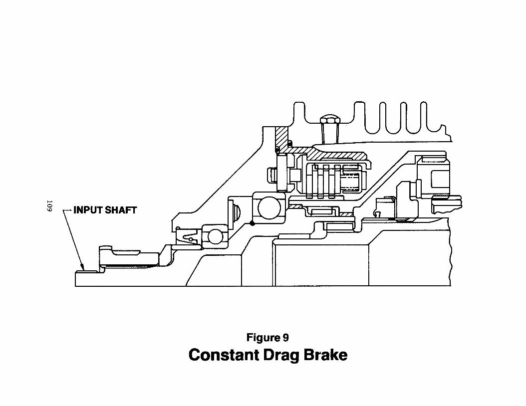
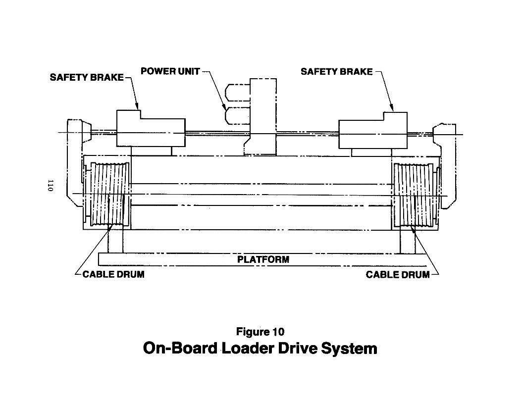
F igu re 10 shows t h e d r i v e system of t h e Boeing Model 747 On-Board Loader which used two brakes i n a dua l load pa th arrangement. des ign of t h e brake as de l ive red w a s as shown i n F igure 1.
The f i n a l
ANALYSIS OF ON-BOARD LOADER BRAKE
Weight of p la t form and payload - 34,000 l b . Torque a t c a b l e drum - 102,000 in-lb. Torque a t brake - 1,090 in-lb.
Brake Design Parameters:
rD = 2.47 i n . r M = 2.47 i n . r g = 2.50 i n . nD = 4 nM = 6
FE = 60 l b . FR = 30 l b . FM = 552 l b . lu = .12-.10 oper. IJ = .06 Min.
99

CHECK CAN SLOPE ANGLE
S u b s t i t u t i n g va lues f o r a l l known t e r m s and t h e minimum c o e f f i c i e n t of f r i c t i o n , t h e above equat ion r e s o l v e s i n t o t h e fol lowing quadra t i c :
172.975 t a n f12 + 20.5079 0 - 14.5885 = 0
So lu t ion of t h e q u a d r a t i c g ives t h e maximum c a m s l o p e ang le which w i l l a l low t h e brake t o support t h e load without s l i pp ing .
Solu t ion : 13 = 13.34O
To allow f o r . t o l e r a n c e s w e w i l l use 0 =: 12.50'
DRIVING AN OPPOSING LOAD (See F igure 6)
Input Torque:
T 1 = FEprDnD + To
= 60 (.11) 2.47 (4) + 1090
T1 = 1155 in-lb
STOPPED WITH LOAD APPLIED (See Figure 7)
Axial Force:
To + F P r M % p =
A prMnM + tanOrg
- 1090 + 30 (.11) 2.47 (6) - . l l (2.47) 6 + tan 12.50° (2.5)
FA = 521.4 l b
For brake t o b e i r r e v e r s i b l e :
TD' TB
TD = F p r n A D D
= 521.4 (.11) 2.47 (4)
TD = 566.7 in- lb 100

TB = FtrB
= FA tanOrB
= 521.4 t a n 12.50° (2.5)
TB = 288.9 in-lb
TD' TB
566.7> 288.9 .*,Brake i s i r r e v e r s i b l e
BRAKE HOLDING MARGIN
TM = FMpr'M%
= (521.4 - 30) -11 (2.47) 6
TM = 801.1 in-lb
Margin:
566.7 + 801.1
1090 -t 'M =
To
Margin = 1.25
DRIVING AN A I D I N G LOAD (See Figure 8)
Input Torque:
= 521.4 c.11 (2.47) 4 - t a n 12.50' (2.511
= 566.7 - 288.9
T1 = 277.8 in-lb
101

102

I I 103

c-c STOPPED Figure 3
ctions Through Driving Members 104

RELIEF GROOVE
CAM GROOVE
t- +
PLAN VIEW SECTION A-A
(UNWRAPPED) Figure 4
07%- 105% Rb
SECTION B-B
CAM GROOVE
LIEF GROOVE
Figure 5
Ball Cam Groove

MODULATING
SPRtNG
Figure 6
Driving an Opposing Load
106

r STATOR
MODULA SPRING
BRAKE
TlNG
Figure 7
With L plie
107
SPRING
L MODULATING SPRING
Figure 8
Driving An Aiding Load 108
109
‘H I
-- --- I I I
I
I I
I I
m
s