lk75a and lk75b · logic gates and gate or gate nor gate/inverter nand gate/inverter * both nor and...
TRANSCRIPT
© TQ Education and Training Ltd 2006
No part of this publication may be reproduced or transmitted inany form or by any means, electronic or mechanical, includingphotocopy, recording or any information storage and retrievalsystem without the express permission of TQ Education andTraining Limited.
All due care has been taken to ensure that the contents of thismanual are accurate and up to date. However, if any errors arediscovered, please inform TQ so the problem may be rectified.
A Packing Contents List is supplied with the equipment.Carefully check the contents of the package(s) against the list. Ifany items are missing or damaged, contact your local TQ Agentor TQ immediately.
LK75A and LK75BElectronic Systems Kits
ASSIGNMENTS BOOK
LK/DB/0206

Assignments Book TQ Education and Training Ltd
Contents
Locktronics LK75A and LK75B
Introduction . . . . . . . . . . . . . . . . . . . . . . . . . . . . . . . . . . . . . . . . . . . . . . . . . . . . . . . . . . . . . . . . . . 1
Locktronics kits: . . . . . . . . . . . . . . . . . . . . . . . . . . . . . . . . . . . . . . . . . . . . . . . . . . . . . . . . . . . . . . . . . . 1
This book . . . . . . . . . . . . . . . . . . . . . . . . . . . . . . . . . . . . . . . . . . . . . . . . . . . . . . . . . . . . . . . . . . . . . . . . . 1
LK75A and LK75B Components . . . . . . . . . . . . . . . . . . . . . . . . . . . . . . . . . . . . . . . . . . 3
Baseboard LK750 (Available Separately). . . . . . . . . . . . . . . . . . . . . . . . . . . . . . . . . . . . . . . . . . . . . 3
D.C Power Supply CU600T (Available Separately) . . . . . . . . . . . . . . . . . . . . . . . . . . . . . . . . . . . . 3
A.C Power Supply CU600AC (Available Separately) . . . . . . . . . . . . . . . . . . . . . . . . . . . . . . . . . . . 4
Lead Set LKLS (Available Separately) . . . . . . . . . . . . . . . . . . . . . . . . . . . . . . . . . . . . . . . . . . . . . . . 4
Current Probe LKCP (Available Separately) . . . . . . . . . . . . . . . . . . . . . . . . . . . . . . . . . . . . . . . . . . 4
Notes to the Supervisor or Teacher . . . . . . . . . . . . . . . . . . . . . . . . . . . . . . . . . . . . . 5
Power Supplies . . . . . . . . . . . . . . . . . . . . . . . . . . . . . . . . . . . . . . . . . . . . . . . . . . . . . . . . . . . . . . . . . . . 5
General Care and Maintenance . . . . . . . . . . . . . . . . . . . . . . . . . . . . . . . . . . . . . . . . . . . . . . . . . . . . . 5
Notes to the Student . . . . . . . . . . . . . . . . . . . . . . . . . . . . . . . . . . . . . . . . . . . . . . . . . . . . . . . . 7
British Standard Symbols . . . . . . . . . . . . . . . . . . . . . . . . . . . . . . . . . . . . . . . . . . . . . . . . . 9
Systems and the Locktronics Modules . . . . . . . . . . . . . . . . . . . . . . . . . . . . . . . . 11
Definitions of a System . . . . . . . . . . . . . . . . . . . . . . . . . . . . . . . . . . . . . . . . . . . . . . . . . . . . . . . . . . . 11
Input Transducer Modules in the LK75 kits. . . . . . . . . . . . . . . . . . . . . . . . . . . . . . . . . . . . . . . . . . 12
Signal Processor Modules in the LK75 Kits . . . . . . . . . . . . . . . . . . . . . . . . . . . . . . . . . . . . . . . . . 12
Output Transducer Modules in the LK75 Kits. . . . . . . . . . . . . . . . . . . . . . . . . . . . . . . . . . . . . . . . 12
Suitable Locktronics Module Combinations. . . . . . . . . . . . . . . . . . . . . . . . . . . . . . . . . . . . . . . . . 13
The Locktronics Modules . . . . . . . . . . . . . . . . . . . . . . . . . . . . . . . . . . . . . . . . . . . . . . . . . . . . . . . . . 14
How to Build Systems with the Locktronics Modules . . . . . . . . . . . . . . . . . . . . . . . . . . . . . . . . 15
Familiarization Assignments . . . . . . . . . . . . . . . . . . . . . . . . . . . . . . . . . . . . . . . . . . . . . 17
1. The Transistor Switch and Transducer Driver . . . . . . . . . . . . . . . . . . . . . . . . . . . . . . . . . . . . . . 182. The Latch . . . . . . . . . . . . . . . . . . . . . . . . . . . . . . . . . . . . . . . . . . . . . . . . . . . . . . . . . . . . . . . . . . 203. Input Transducers and Input Control . . . . . . . . . . . . . . . . . . . . . . . . . . . . . . . . . . . . . . . . . . . . . 214. Logic Gates. . . . . . . . . . . . . . . . . . . . . . . . . . . . . . . . . . . . . . . . . . . . . . . . . . . . . . . . . . . . . . . . . 225. Truth Tables (Needs LK75B Kit). . . . . . . . . . . . . . . . . . . . . . . . . . . . . . . . . . . . . . . . . . . . . . . . . 236. Pulse Generator (Needs LK75B Kit). . . . . . . . . . . . . . . . . . . . . . . . . . . . . . . . . . . . . . . . . . . . . . 247. Counter/Display Module (Needs LK75B Kit). . . . . . . . . . . . . . . . . . . . . . . . . . . . . . . . . . . . . . . . 258. Output Transducers . . . . . . . . . . . . . . . . . . . . . . . . . . . . . . . . . . . . . . . . . . . . . . . . . . . . . . . . . . 26
TQ Education and Training Ltd Assignments Book
Operational Amplifier Assignments . . . . . . . . . . . . . . . . . . . . . . . . . . . . . . . . . . . . 27
9. Non-inverting Amplifier . . . . . . . . . . . . . . . . . . . . . . . . . . . . . . . . . . . . . . . . . . . . . . . . . . . . . . . . 2810. The Comparator (Needs LK75B Kit) . . . . . . . . . . . . . . . . . . . . . . . . . . . . . . . . . . . . . . . . . . . . . 3011. The Sound Sensor (Microphone) (Needs LK75B Kit) . . . . . . . . . . . . . . . . . . . . . . . . . . . . . . . . 31
Problem Solving (Needs LK75B Kit) . . . . . . . . . . . . . . . . . . . . . . . . . . . . . . . . . . . . 33
12. Problem Solving Example. . . . . . . . . . . . . . . . . . . . . . . . . . . . . . . . . . . . . . . . . . . . . . . . . . . . . 3413. More Problem Solving Exercises to Try . . . . . . . . . . . . . . . . . . . . . . . . . . . . . . . . . . . . . . . . . . 36
Appendix . . . . . . . . . . . . . . . . . . . . . . . . . . . . . . . . . . . . . . . . . . . . . . . . . . . . . . . . . . . . . . . . . . . . . 37
Logic Symbols . . . . . . . . . . . . . . . . . . . . . . . . . . . . . . . . . . . . . . . . . . . . . . . . . . . . . . . . . . . . . . . . . . . 37
Truth Tables . . . . . . . . . . . . . . . . . . . . . . . . . . . . . . . . . . . . . . . . . . . . . . . . . . . . . . . . . . . . . . . . . . . . . . 38
LK75A and LK75BASSIGNMENTS BOOK
Introduction
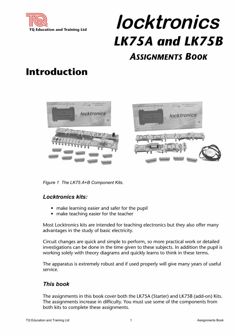
Figure 1 The LK75 A+B Component Kits.
Locktronics kits:
• make learning easier and safer for the pupil• make teaching easier for the teacher
Most Locktronics kits are intended for teaching electronics but they also offer many advantages in the study of basic electricity.
Circuit changes are quick and simple to perform, so more practical work or detailed investigations can be done in the time given to these subjects. In addition the pupil is working solely with theory diagrams and quickly learns to think in these terms.
The apparatus is extremely robust and if used properly will give many years of useful service.
This book
The assignments in this book cover both the LK75A (Starter) and LK75B (add-on) Kits. The assignments increase in difficulty. You must use some of the components from both kits to complete these assignments.
TQ Education and Training Ltd 1 Assignments Book

Locktronics LK75A and LK75B
Assignments Book 2 TQ Education and Training Ltd
Locktronics LK75A and LK75B
LK75A and LK75B ComponentsThe LK75A and LK75B Kits ( shown in Figure 1) are component kits. TQ recommends that the dedicated LK750 Baseboard, power supplies and leads (available separately) are used with the kits.
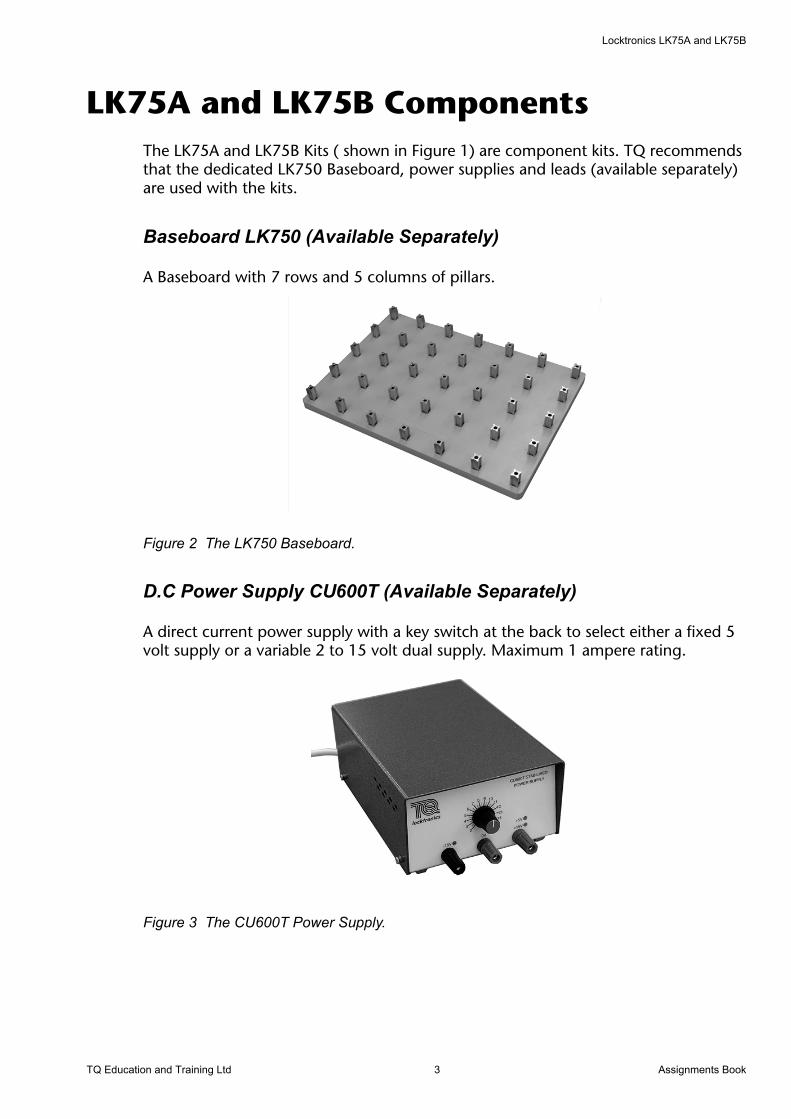
Baseboard LK750 (Available Separately)
A Baseboard with 7 rows and 5 columns of pillars.
Figure 2 The LK750 Baseboard.
D.C Power Supply CU600T (Available Separately)
A direct current power supply with a key switch at the back to select either a fixed 5 volt supply or a variable 2 to 15 volt dual supply. Maximum 1 ampere rating.
Figure 3 The CU600T Power Supply.
TQ Education and Training Ltd 3 Assignments Book

Locktronics LK75A and LK75B
A.C Power Supply CU600AC (Available Separately)
An alternating current source power supply with a fixed 15 V A.C Output. Maximum 500 mA rating.
Figure 4 The CU600AC Power Supply.
Lead Set LKLS (Available Separately)
Figure 5 The LKLS Lead Set.
Current Probe LKCP (Available Separately)
Figure 6 The LKCP Current Probe.
Assignments Book 4 TQ Education and Training Ltd

Locktronics LK75A and LK75B
Notes to the Supervisor or Teacher
Power Supplies
The CU600 power supply units contain short circuit protection. The CU600T gives an audible warning of a short circuit. This reduces the possibility of circuits being left in a short circuit condition.
Use the recommended power supplies for these assignments or suitably fused and protected low voltage power supplies or batteries of the correct voltage.
General Care and Maintenance
During regular use the kits may become dirty.
Clean the polystyrene component carriers with a damp cloth and a little liquid detergent. Never use spirit solvent. Make sure the carriers are dry before use.
The phosphor bronze contacts are self-cleaning and will retain their proper shapes in normal use. If for any reason they are bent out of shape, use a pair of long-nosed pliers to correct the shape.
CAUTION
Contact with resin bonded material such as chipboard, plywood, etc. can damage the plating on the carrier contact springs thus impairing their efficiency. Do not store the components in such material.
TQ Education and Training Ltd 5 Assignments Book

Locktronics LK75A and LK75B
Assignments Book 6 TQ Education and Training Ltd

Locktronics LK75A and LK75B
Notes to the StudentAs you work through these assignments:
• Copy each individual circuit used into your notebook, together with its title.
• In your diagrams, always use the correct symbol for the components.
• Make a note of any important facts or information which you have learned and may need to recall for your examinations. Brief notes are usually enough.
• Disconnect the power supply leads before making any circuit changes. This will prevent accidental damage to components, particularly in assignments using transistors and other semi-conductor devices.
• Note that some components are different, even though they look the same they may not perform in the same way. There are two different types of bulbs, and several different resistors.
Depending upon the particular subject and examination board setting your exam, you may not need to cover all the assignments given. However, check with your teacher to find out about this.
We hope you find the assignments interesting and stimulating enough to make you want to find out more about the exciting subjects of electronics and electricity which are changing the world in which we live.
TQ Education and Training Ltd.
TQ Education and Training Ltd 7 Assignments Book

Locktronics LK75A and LK75B
Assignments Book 8 TQ Education and Training Ltd
Locktronics LK75A and LK75B
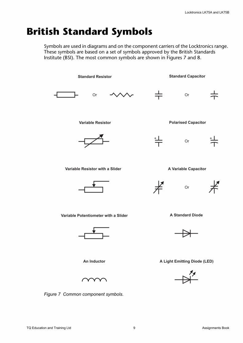
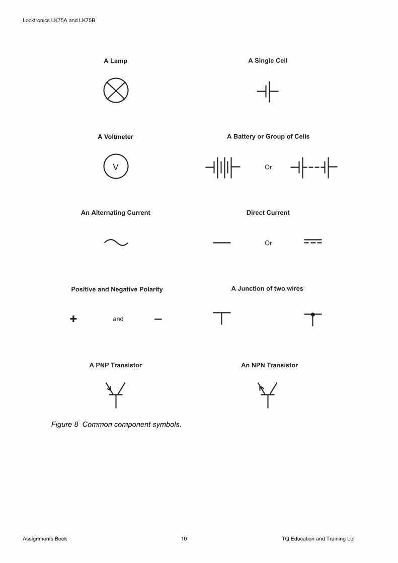
British Standard SymbolsSymbols are used in diagrams and on the component carriers of the Locktronics range. These symbols are based on a set of symbols approved by the British Standards Institute (BSI). The most common symbols are shown in Figures 7 and 8.
Figure 7 Common component symbols.
+ +
Standard Resistor
Or
Variable Resistor
Variable Resistor with a Slider
Variable Potentiometer with a Slider
Standard Capacitor
Or
Polarised Capacitor
Or
A Standard Diode
A Variable Capacitor
Or
An Inductor A Light Emitting Diode (LED)
TQ Education and Training Ltd 9 Assignments Book
Locktronics LK75A and LK75B
Figure 8 Common component symbols.
A Lamp
A Voltmeter
An Alternating Current
Positive and Negative Polarity
A Single Cell
A Battery or Group of Cells
Or
A Junction of two wires
Direct Current
Or
V
+_
and
A PNP Transistor An NPN Transistor
Assignments Book 10 TQ Education and Training Ltd
Locktronics LK75A and LK75B
Systems and the Locktronics Modules
Definitions of a System
• a complex whole• a set of connected things or parts• an organized body of material or immaterial things.
An electronic system is made of a selection of electronic modules that are arranged to do a certain job.
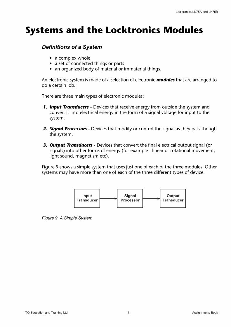
There are three main types of electronic modules:
1. Input Transducers - Devices that receive energy from outside the system and convert it into electrical energy in the form of a signal voltage for input to the system.
2. Signal Processors - Devices that modify or control the signal as they pass though the system.
3. Output Transducers - Devices that convert the final electrical output signal (or signals) into other forms of energy (for example - linear or rotational movement, light sound, magnetism etc).
Figure 9 shows a simple system that uses just one of each of the three modules. Other systems may have more than one of each of the three different types of device.
Figure 9 A Simple System
TQ Education and Training Ltd 11 Assignments Book
Locktronics LK75A and LK75B
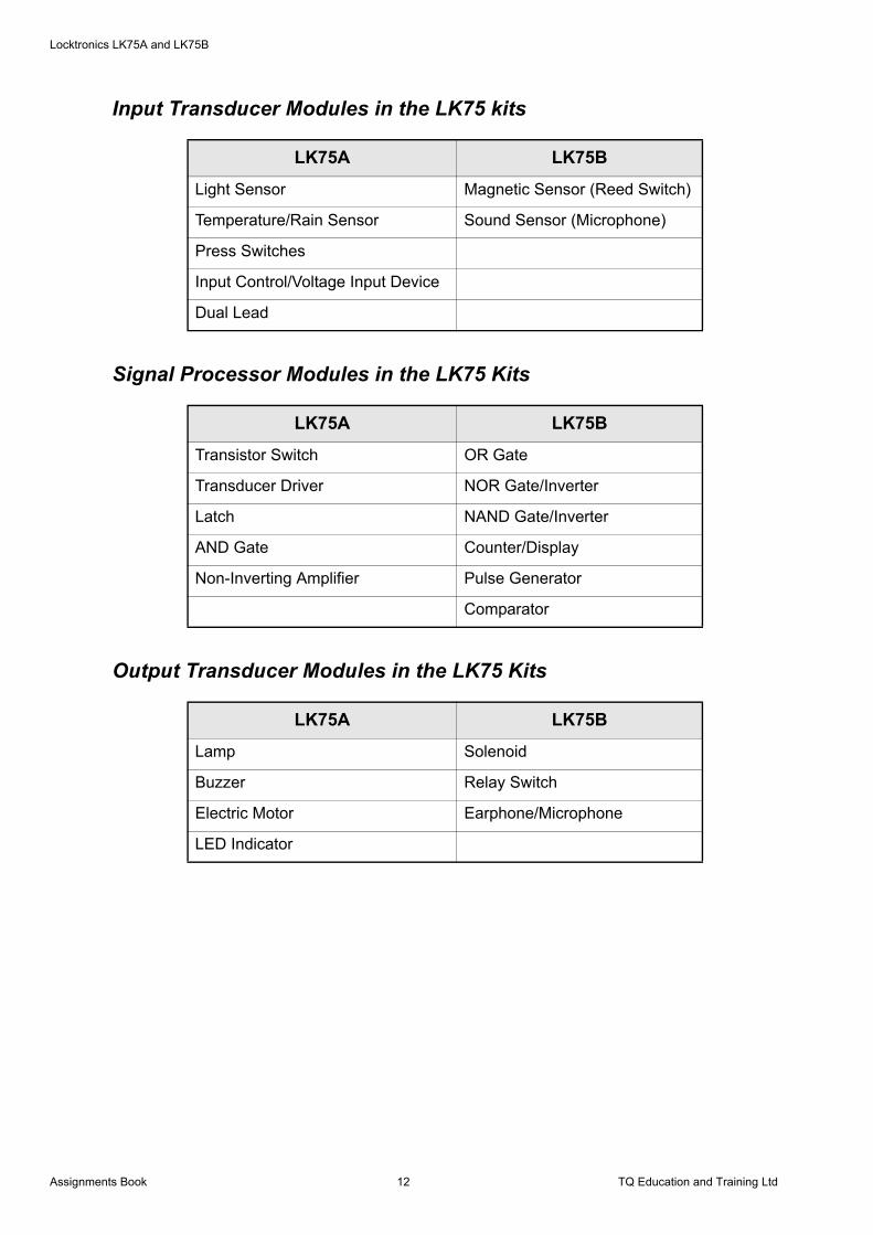
Input Transducer Modules in the LK75 kits
Signal Processor Modules in the LK75 Kits
Output Transducer Modules in the LK75 Kits
LK75A LK75B
Light Sensor Magnetic Sensor (Reed Switch)
Temperature/Rain Sensor Sound Sensor (Microphone)
Press Switches
Input Control/Voltage Input Device
Dual Lead
LK75A LK75B
Transistor Switch OR Gate
Transducer Driver NOR Gate/Inverter
Latch NAND Gate/Inverter
AND Gate Counter/Display
Non-Inverting Amplifier Pulse Generator
Comparator
LK75A LK75B
Lamp Solenoid
Buzzer Relay Switch
Electric Motor Earphone/Microphone
LED Indicator
Assignments Book 12 TQ Education and Training Ltd
Locktronics LK75A and LK75B
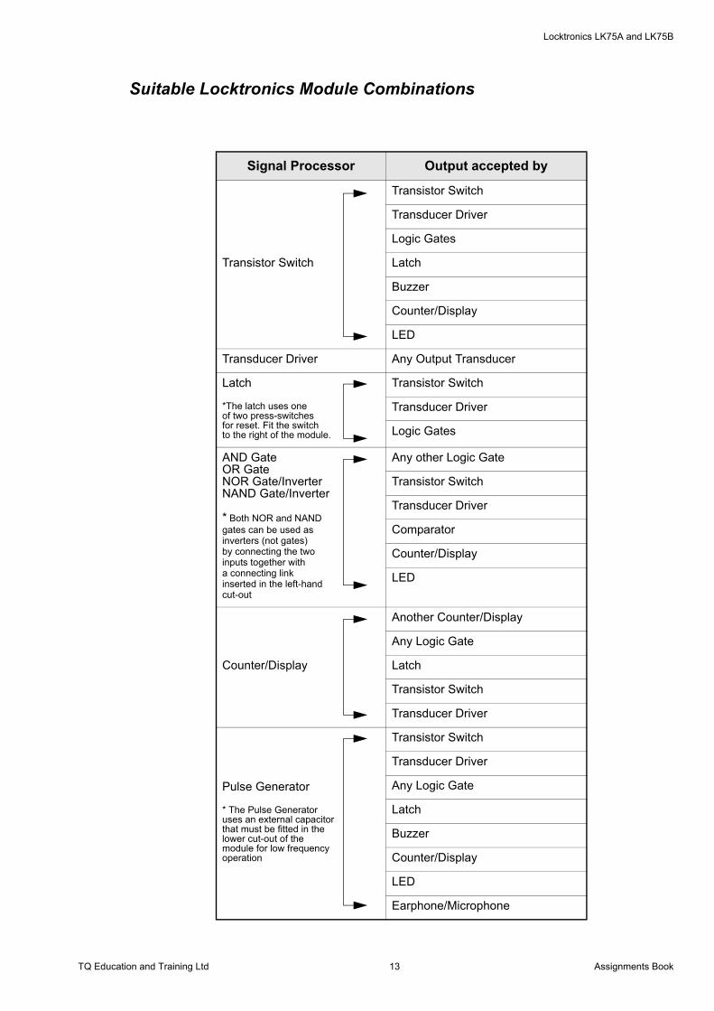
Suitable Locktronics Module Combinations
Signal Processor Output accepted by
Transistor Switch
Transistor Switch
Transducer Driver
Logic Gates
Latch
Buzzer
Counter/Display
LED
Transducer Driver Any Output Transducer
Latch
*The latch uses oneof two press-switchesfor reset. Fit the switchto the right of the module.
Transistor Switch
Transducer Driver
Logic Gates
AND GateOR GateNOR Gate/InverterNAND Gate/Inverter
* Both NOR and NANDgates can be used asinverters (not gates)by connecting the twoinputs together witha connecting linkinserted in the left-handcut-out
Any other Logic Gate
Transistor Switch
Transducer Driver
Comparator
Counter/Display
LED
Counter/Display
Another Counter/Display
Any Logic Gate
Latch
Transistor Switch
Transducer Driver
Pulse Generator
* The Pulse Generatoruses an external capacitorthat must be fitted in thelower cut-out of the module for low frequencyoperation
Transistor Switch
Transducer Driver
Any Logic Gate
Latch
Buzzer
Counter/Display
LED
Earphone/Microphone
TQ Education and Training Ltd 13 Assignments Book
Locktronics LK75A and LK75B
The Locktronics Modules
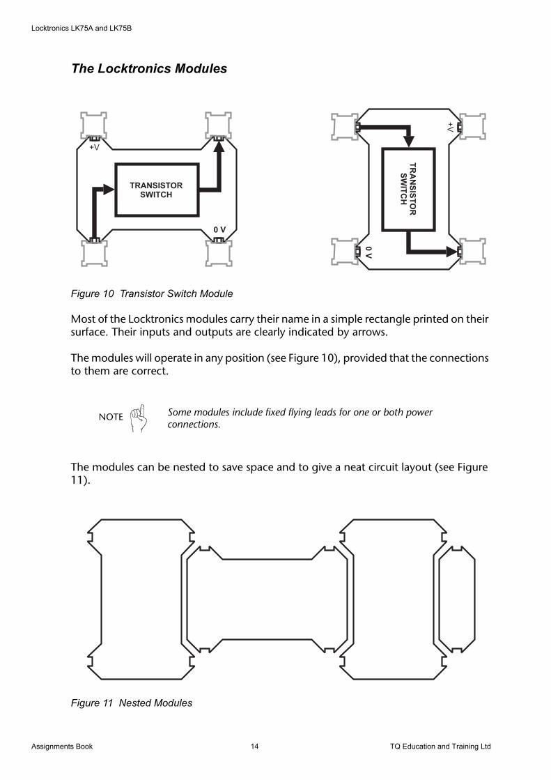
Figure 10 Transistor Switch Module
Most of the Locktronics modules carry their name in a simple rectangle printed on their surface. Their inputs and outputs are clearly indicated by arrows.
The modules will operate in any position (see Figure 10), provided that the connections to them are correct.
The modules can be nested to save space and to give a neat circuit layout (see Figure 11).
Figure 11 Nested Modules
NOTE Some modules include fixed flying leads for one or both power connections.
Assignments Book 14 TQ Education and Training Ltd
Locktronics LK75A and LK75B
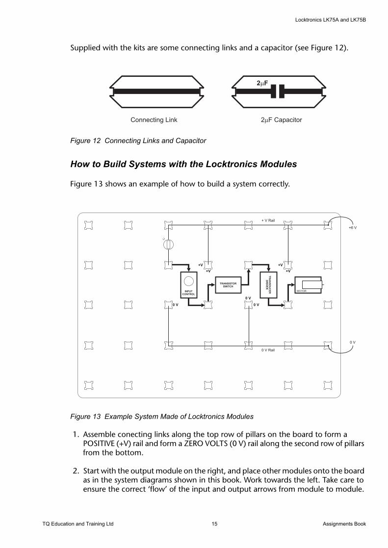
Supplied with the kits are some connecting links and a capacitor (see Figure 12).
Figure 12 Connecting Links and Capacitor
How to Build Systems with the Locktronics Modules
Figure 13 shows an example of how to build a system correctly.
Figure 13 Example System Made of Locktronics Modules
1. Assemble conecting links along the top row of pillars on the board to form a POSITIVE (+V) rail and form a ZERO VOLTS (0 V) rail along the second row of pillars from the bottom.
2. Start with the output module on the right, and place other modules onto the board as in the system diagrams shown in this book. Work towards the left. Take care to ensure the correct ‘flow’ of the input and output arrows from module to module.
TQ Education and Training Ltd 15 Assignments Book

Locktronics LK75A and LK75B
3. Fit connecting links to the +V and 0V rails from each module. Note that in many cases, one link will connect two modules. If a module has a flying lead, insert the flat blade of the lead down the side of a pillar, between the pillar and a connecting link.
4. Re-check your circuit against the diagram shown in this book.
5. Check your d.c supply - Set it at 6 V.
6. When you are sure that all things are correct, switch on the supply.
The system shown in Figure 13 is a ‘dark’ activated system. Build it and make sure that light falls on the LDR (light dependant resistor). If the motor is turning, adjust the input control until it stops. Cover the LDR. What happens?
When you understand how the system works, find out what happens if a latch is placed between the Transistor Switch and the Transducer Driver. Insert a press-switch in the right hand cut-out of the Latch in order to give a reset facility.
You will need to rearrange the system with extra connecting links and turn two of the modules by 90°.
If you have both kits, you could use the Counter/Display to count the number of times a system is activated, but remember that if the system includes a Latch, it must be reset after each display change.
Try using different sensors instead of the light sensor. Do not use the microphone - this is dealt with in a later assignment.
Assignments Book 16 TQ Education and Training Ltd

Locktronics LK75A and LK75B
Familiarization AssignmentsThese assignments help you to study the action of each of the modules in turn.
TQ Education and Training Ltd 17 Assignments Book
Locktronics LK75A and LK75B
1. The Transistor Switch and Transducer Driver
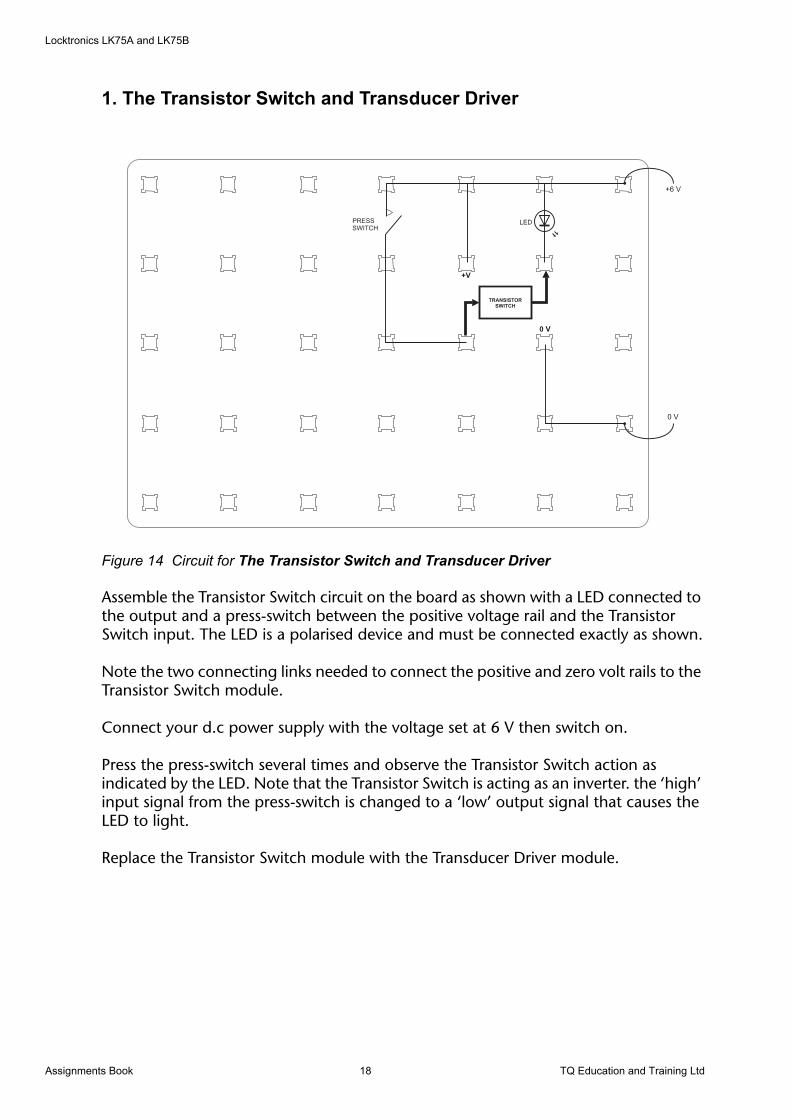
Figure 14 Circuit for The Transistor Switch and Transducer Driver
Assemble the Transistor Switch circuit on the board as shown with a LED connected to the output and a press-switch between the positive voltage rail and the Transistor Switch input. The LED is a polarised device and must be connected exactly as shown.
Note the two connecting links needed to connect the positive and zero volt rails to the Transistor Switch module.
Connect your d.c power supply with the voltage set at 6 V then switch on.
Press the press-switch several times and observe the Transistor Switch action as indicated by the LED. Note that the Transistor Switch is acting as an inverter. the ‘high’ input signal from the press-switch is changed to a ‘low’ output signal that causes the LED to light.
Replace the Transistor Switch module with the Transducer Driver module.
Assignments Book 18 TQ Education and Training Ltd
Locktronics LK75A and LK75B
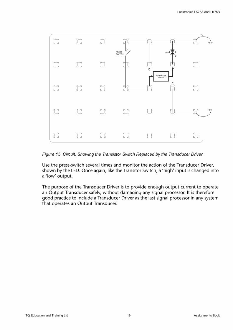
Figure 15 Circuit, Showing the Transistor Switch Replaced by the Transducer Driver
Use the press-switch several times and monitor the action of the Transducer Driver, shown by the LED. Once again, like the Transitor Switch, a ‘high’ input is changed into a ‘low’ output.
The purpose of the Transducer Driver is to provide enough output current to operate an Output Transducer safely, without damaging any signal processor. It is therefore good practice to include a Transducer Driver as the last signal processor in any system that operates an Output Transducer.
TQ Education and Training Ltd 19 Assignments Book
Locktronics LK75A and LK75B
2. The Latch
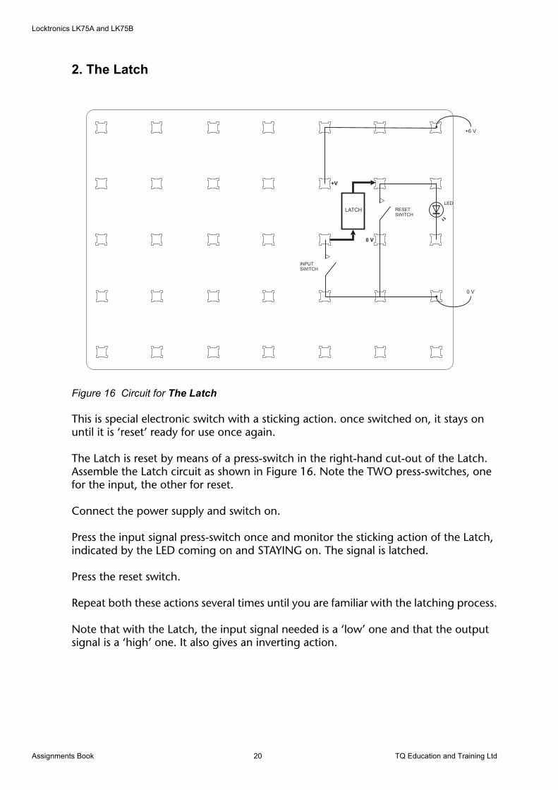
Figure 16 Circuit for The Latch
This is special electronic switch with a sticking action. once switched on, it stays on until it is ‘reset’ ready for use once again.
The Latch is reset by means of a press-switch in the right-hand cut-out of the Latch. Assemble the Latch circuit as shown in Figure 16. Note the TWO press-switches, one for the input, the other for reset.
Connect the power supply and switch on.
Press the input signal press-switch once and monitor the sticking action of the Latch, indicated by the LED coming on and STAYING on. The signal is latched.
Press the reset switch.
Repeat both these actions several times until you are familiar with the latching process.
Note that with the Latch, the input signal needed is a ‘low’ one and that the output signal is a ‘high’ one. It also gives an inverting action.
Assignments Book 20 TQ Education and Training Ltd
Locktronics LK75A and LK75B
3. Input Transducers and Input Control
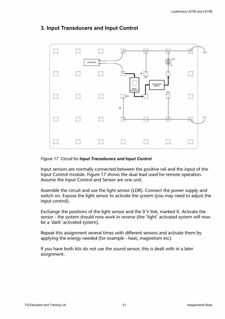
Figure 17 Circuit for Input Transducers and Input Control
Input sensors are normally connected between the positive rail and the input of the Input Control module. Figure 17 shows the dual lead used for remote operation. Assume the Input Control and Sensor are one unit.
Assemble the circuit and use the light sensor (LDR). Connect the power supply and switch on. Expose the light sensor to activate the system (you may need to adjust the input control).
Exchange the positions of the light sensor and the 0 V link, marked X. Activate the sensor - the system should now work in reverse (the ‘light’ activated system will now be a ‘dark’ activated system).
Repeat this assignment several times with different sensors and activate them by applying the energy needed (for example - heat, magnetism etc).
If you have both kits do not use the sound sensor, this is dealt with in a later assignment.
TQ Education and Training Ltd 21 Assignments Book
Locktronics LK75A and LK75B
4. Logic Gates
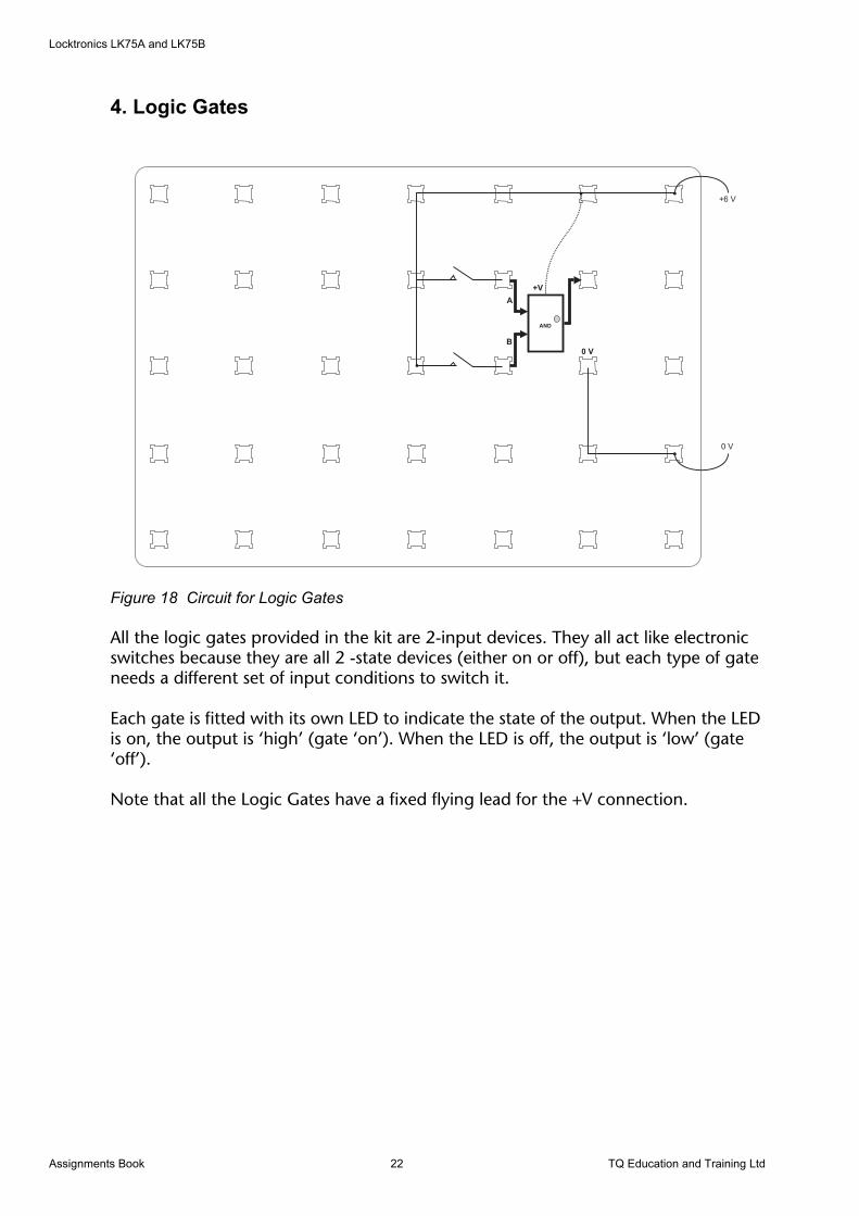
Figure 18 Circuit for Logic Gates
All the logic gates provided in the kit are 2-input devices. They all act like electronic switches because they are all 2 -state devices (either on or off), but each type of gate needs a different set of input conditions to switch it.
Each gate is fitted with its own LED to indicate the state of the output. When the LED is on, the output is ‘high’ (gate ‘on’). When the LED is off, the output is ‘low’ (gate ‘off’).
Note that all the Logic Gates have a fixed flying lead for the +V connection.
Assignments Book 22 TQ Education and Training Ltd
Locktronics LK75A and LK75B
5. Truth Tables (Needs LK75B Kit)
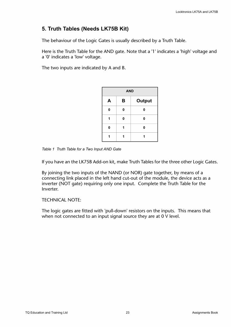
The behaviour of the Logic Gates is usually described by a Truth Table.
Here is the Truth Table for the AND gate. Note that a '1' indicates a 'high' voltage and a '0' indicates a 'low' voltage.
The two inputs are indicated by A and B.
Table 1 Truth Table for a Two Input AND Gate
If you have an the LK75B Add-on kit, make Truth Tables for the three other Logic Gates.
By joining the two inputs of the NAND (or NOR) gate together, by means of a connecting link placed in the left hand cut-out of the module, the device acts as a inverter (NOT gate) requiring only one input. Complete the Truth Table for the Inverter.
TECHNICAL NOTE:
The logic gates are fitted with 'pull-down' resistors on the inputs. This means that when not connected to an input signal source they are at 0 V level.
AND
A B Output
0 0 0
1 0 0
0 1 0
1 1 1
TQ Education and Training Ltd 23 Assignments Book
Locktronics LK75A and LK75B
6. Pulse Generator (Needs LK75B Kit)
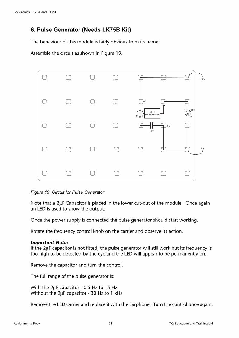
The behaviour of this module is fairly obvious from its name.
Assemble the circuit as shown in Figure 19.
Figure 19 Circuit for Pulse Generator
Note that a 2µF Capacitor is placed in the lower cut-out of the module. Once again an LED is used to show the output.
Once the power supply is connected the pulse generator should start working.
Rotate the frequency control knob on the carrier and observe its action.
Important Note:If the 2µF capacitor is not fitted, the pulse generator will still work but its frequency is too high to be detected by the eye and the LED will appear to be permanently on.
Remove the capacitor and turn the control.
The full range of the pulse generator is:
With the 2µF capacitor - 0.5 Hz to 15 HzWithout the 2µF capacitor - 30 Hz to 1 kHz
Remove the LED carrier and replace it with the Earphone. Turn the control once again.
+6 V
0 V
LED
0 V
+V
PULSEGENERATOR
2 F�
Assignments Book 24 TQ Education and Training Ltd
Locktronics LK75A and LK75B
7. Counter/Display Module (Needs LK75B Kit)
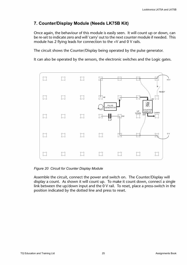
Once again, the behaviour of this module is easily seen. It will count up or down, can be re-set to indicate zero and will 'carry' out to the next counter module if needed. This module has 2 flying leads for connection to the +V and 0 V rails.
The circuit shows the Counter/Display being operated by the pulse generator.
It can also be operated by the sensors, the electronic switches and the Logic gates.
Figure 20 Circuit for Counter Display Module
Assemble the circuit, connect the power and switch on. The Counter/Display will display a count. As shown it will count up. To make it count down, connect a single link between the up/down input and the 0 V rail. To reset, place a press-switch in the position indicated by the dotted line and press to reset.
+6 V
0 V
0 V
+V
PULSEGENERATOR
2 F�
8COUNTERDISPLAY
+V
0 V
RESET
UPDOWN CARRY
TQ Education and Training Ltd 25 Assignments Book
Locktronics LK75A and LK75B
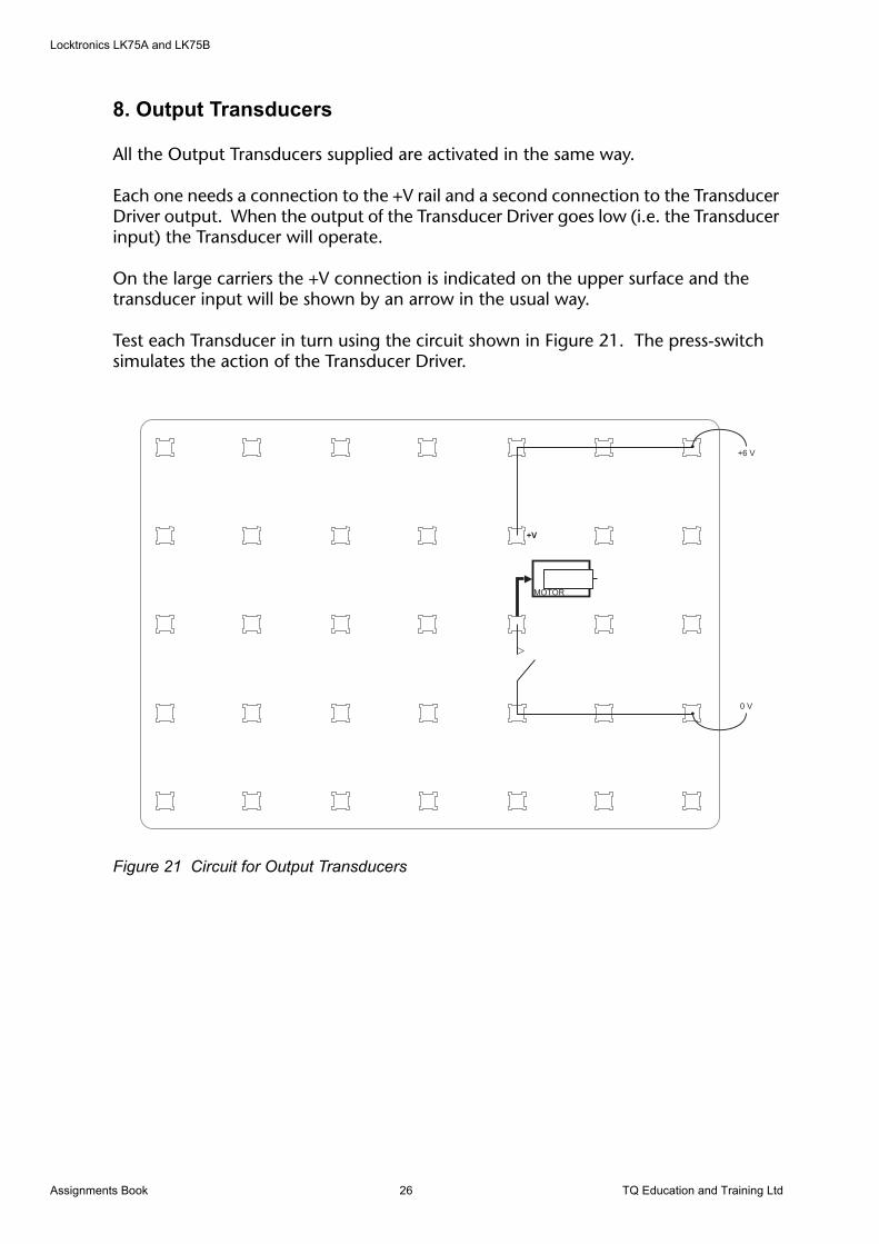
8. Output Transducers
All the Output Transducers supplied are activated in the same way.
Each one needs a connection to the +V rail and a second connection to the Transducer Driver output. When the output of the Transducer Driver goes low (i.e. the Transducer input) the Transducer will operate.
On the large carriers the +V connection is indicated on the upper surface and the transducer input will be shown by an arrow in the usual way.
Test each Transducer in turn using the circuit shown in Figure 21. The press-switch simulates the action of the Transducer Driver.
Figure 21 Circuit for Output Transducers
+6 V
0 V
+V
MOTOR
Assignments Book 26 TQ Education and Training Ltd
Locktronics LK75A and LK75B
Operational Amplifier AssignmentsThe next few assignments use the operational amplifier (Op-amp). It is a very high gain amplifier that was designed for use in early computers.
One of the first and still the most common type of Op-amp is the 741, developed during the 1960’s and 1970’s. Modern Op-amps have improved features, but the basic design is still identical.
The Op-amp supplied in the LK75 A and B is fitted in two modules:
The Non-inverting Amplifier
The Comparator
The Op-amp used in the kits is a dual version (two Op-amps in one package) of the 741 and is connected so that it can operate from a single supply. Each module uses the Op-amp in a slightly different way. For more information on Op-amps, try the Locktronics LK80 Operational Amplifier Kit.
TQ Education and Training Ltd 27 Assignments Book
Locktronics LK75A and LK75B
9. Non-inverting Amplifier
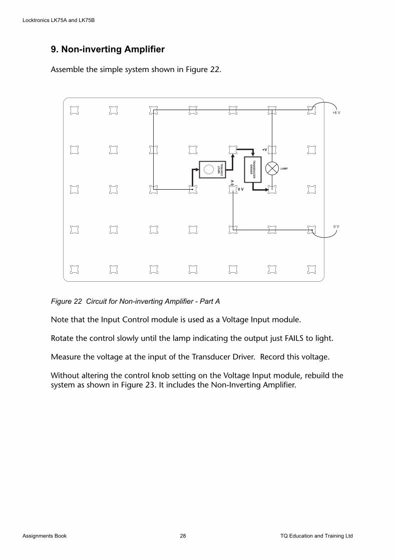
Assemble the simple system shown in Figure 22.
Figure 22 Circuit for Non-inverting Amplifier - Part A
Note that the Input Control module is used as a Voltage Input module.
Rotate the control slowly until the lamp indicating the output just FAILS to light.
Measure the voltage at the input of the Transducer Driver. Record this voltage.
Without altering the control knob setting on the Voltage Input module, rebuild the system as shown in Figure 23. It includes the Non-Inverting Amplifier.
INP
UT
CO
NT
RO
L
0V
TR
AN
SD
UC
ER
DR
IVE
R
0 V
+V
+6 V
0 V
LAMP
Assignments Book 28 TQ Education and Training Ltd

Locktronics LK75A and LK75B
Figure 23 Circuit for Non-inverting Amplifier - Part B
Set the amplifier gain to maximum by rotating the gain control knob fully clockwise.
If you have not touched the voltage input the lamp should now be lit. Once again rotate the control knob on the Voltage Input Module until the lamp just fails to light.
Measure the voltage at the input of the Transducer Driver. Is it the same as before?
Now measure the voltage at the input to the Non-inverting Amplifier, compare the two voltages and complete the following sentence:
The Non-inverting Amplifier is used to ……....... the signal voltages from any ….. ………----….. before being passed on to a signal processor.
Repeat the assignment with the amplifier gain set at different levels. What do you find from the results?
INPUTCONTROL
0 V
TR
AN
SD
UC
ER
DR
IVE
R
0 V
+V
+6 V
0 V
LAMP
NON-INVERTINGAMPLIFIER
+V
0 V
TQ Education and Training Ltd 29 Assignments Book
Locktronics LK75A and LK75B
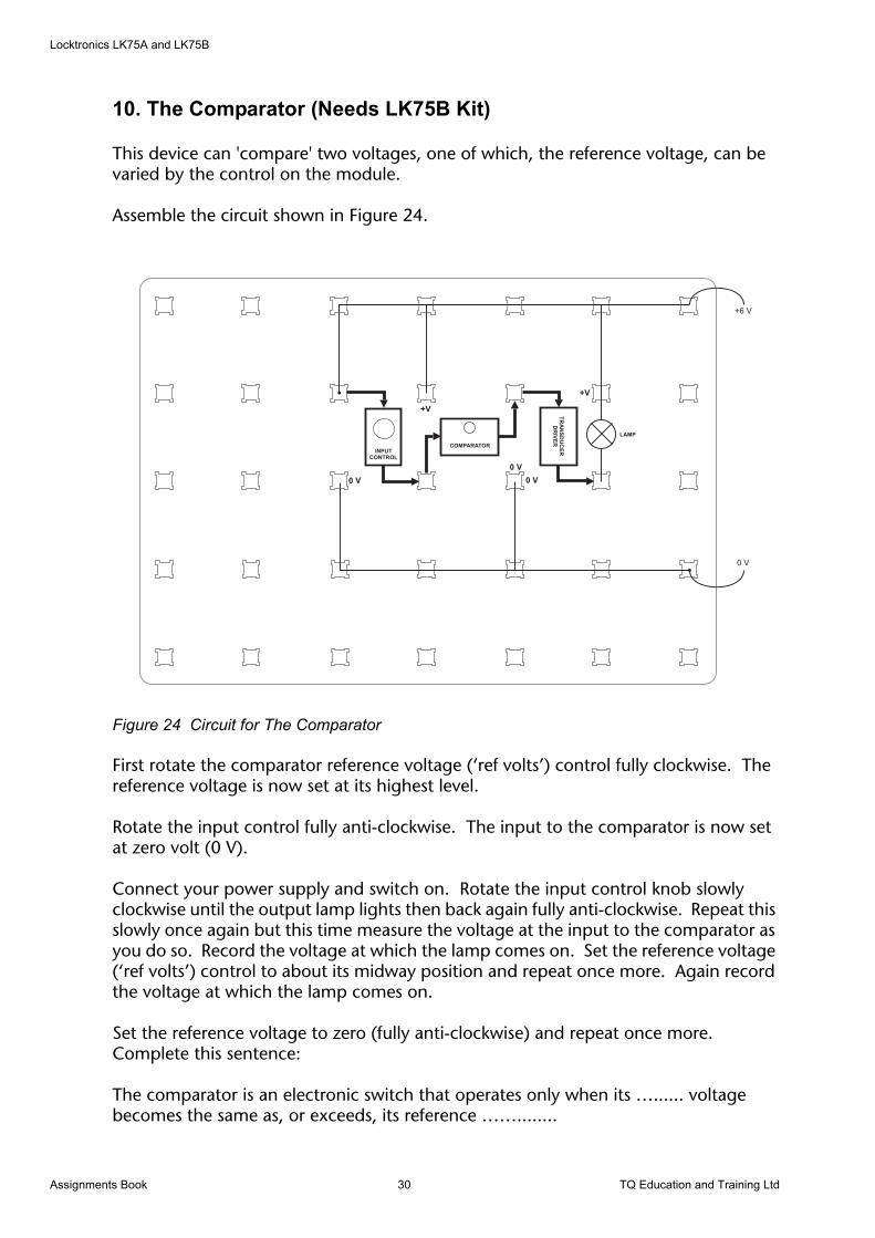
10. The Comparator (Needs LK75B Kit)
This device can 'compare' two voltages, one of which, the reference voltage, can be varied by the control on the module.
Assemble the circuit shown in Figure 24.
Figure 24 Circuit for The Comparator
First rotate the comparator reference voltage (‘ref volts’) control fully clockwise. The reference voltage is now set at its highest level.
Rotate the input control fully anti-clockwise. The input to the comparator is now set at zero volt (0 V).
Connect your power supply and switch on. Rotate the input control knob slowly clockwise until the output lamp lights then back again fully anti-clockwise. Repeat this slowly once again but this time measure the voltage at the input to the comparator as you do so. Record the voltage at which the lamp comes on. Set the reference voltage (‘ref volts’) control to about its midway position and repeat once more. Again record the voltage at which the lamp comes on.
Set the reference voltage to zero (fully anti-clockwise) and repeat once more. Complete this sentence:
The comparator is an electronic switch that operates only when its …...... voltage becomes the same as, or exceeds, its reference ……........
INPUTCONTROL
0 V
TR
AN
SD
UC
ER
DR
IVE
R
0 V
+V
+6 V
0 V
LAMP
COMPARATOR
+V
0 V
Assignments Book 30 TQ Education and Training Ltd

Locktronics LK75A and LK75B
11. The Sound Sensor (Microphone) (Needs LK75B Kit)
Assemble the system shown in Figure 25.
Figure 25 Circuit for The Sound Sensor
Note that the microphone, unlike all the other input transducers (Assignment 3), is connected to the 0 V rail instead of the +V rail. This is because it generates a potential difference across its connections in proportion to the amplitude of sound it receives. The other input transducers change their resistance (or simply switch on and off) , so they need a current to pass through them in order to create a change in voltage across them.
The system shown is a sound operated alarm. The sound level which will operate the alarm can be adjusted by using the input control in the usual way.
When you have tested the system, use the comparator instead of the non-inverting amplifier.
INPUTCONTROL
0 V
TR
AN
SD
UC
ER
DR
IVE
R
0 V
+V
+6 V
0 V
+V
NON-INVERTINGAMPLIFIER
TR
AN
SIS
TO
RS
WIT
CH
0 V
+V
0 V
+V
LATCH
BUZZER
MIC0
V
R
TQ Education and Training Ltd 31 Assignments Book

Locktronics LK75A and LK75B
Assignments Book 32 TQ Education and Training Ltd

Locktronics LK75A and LK75B
Problem Solving (Needs LK75B Kit)Your experience with the modules should now allow you to look at problems and create one or more solutions.
The normally accepted technique for solving problems using Electronic Systems modules is to use these simple rules:
1. Decide what the OUTPUT(S) of the system is (are) going to be.
2. Decide what the INPUT(S) is (are) going to be.
3. Decide which SIGNAL PROCESSOR(S) is (are) needed to produce the output you need.
4. Produce a design on paper using systems 'blocks'.
5. Assemble the prototype system.
6. Test the system to see if it fulfils ALL the desired functions.
7. Produce the second, modified design, on paper.
8. Assemble and test the modified system.
LOCKTRONICS SYSTEMS MODULES are particularly suited for problem solving exercises because of the speed at which modifications to a system may be made.
TQ Education and Training Ltd 33 Assignments Book
Locktronics LK75A and LK75B
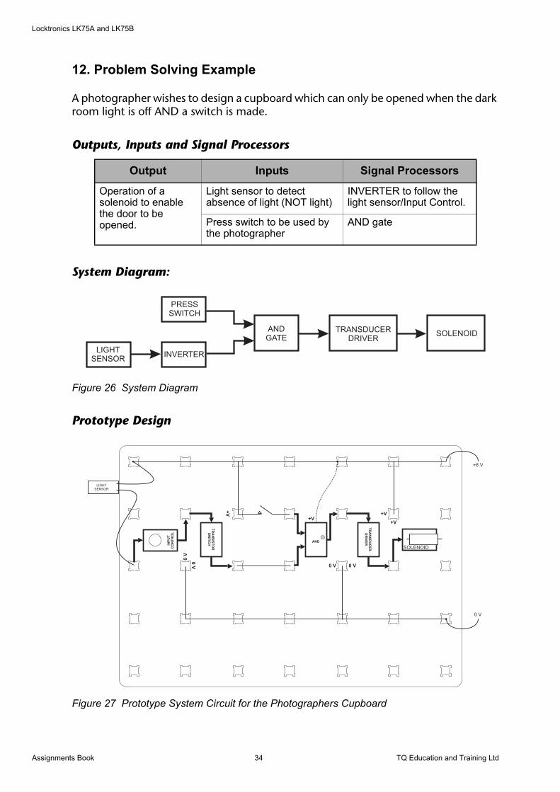
12. Problem Solving Example
A photographer wishes to design a cupboard which can only be opened when the dark room light is off AND a switch is made.
Outputs, Inputs and Signal Processors
System Diagram:
Figure 26 System Diagram
Prototype Design
Figure 27 Prototype System Circuit for the Photographers Cupboard
Output Inputs Signal Processors
Operation of a solenoid to enable the door to be opened.
Light sensor to detect absence of light (NOT light)
INVERTER to follow the light sensor/Input Control.
Press switch to be used by the photographer
AND gate
PRESSSWITCH
LIGHTSENSOR
INVERTER
ANDGATE
TRANSDUCERDRIVER
SOLENOID
INP
UT
CO
NT
RO
L
0V
TR
AN
SD
UC
ER
DR
IVE
R
0 V
+V
+6 V
0 V
TR
AN
SIS
TO
RS
WIT
CH
+V
+V
0V
LIGHTSENSOR
AND
+V
0 V
SOLENOID
Assignments Book 34 TQ Education and Training Ltd
Locktronics LK75A and LK75B
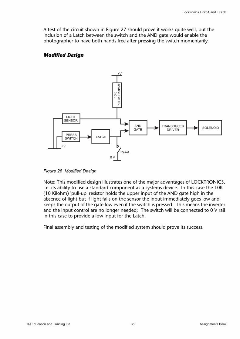
A test of the circuit shown in Figure 27 should prove it works quite well, but the inclusion of a Latch between the switch and the AND gate would enable the photographer to have both hands free after pressing the switch momentarily.
Modified Design
Figure 28 Modified Design
Note: This modified design illustrates one of the major advantages of LOCKTRONICS, i.e. its ability to use a standard component as a systems device. In this case the 10K (10 Kilohm) 'pull-up' resistor holds the upper input of the AND gate high in the absence of light but if light falls on the sensor the input immediately goes low and keeps the output of the gate low even if the switch is pressed. This means the inverter and the input control are no longer needed; The switch will be connected to 0 V rail in this case to provide a low input for the Latch.
Final assembly and testing of the modified system should prove its success.
PRESSSWITCH
LIGHTSENSOR
ANDGATE
TRANSDUCERDRIVER
SOLENOID
10K
Pull
up
Resis
tor
LATCH
0 V
0 V
Reset
+V
TQ Education and Training Ltd 35 Assignments Book
Locktronics LK75A and LK75B
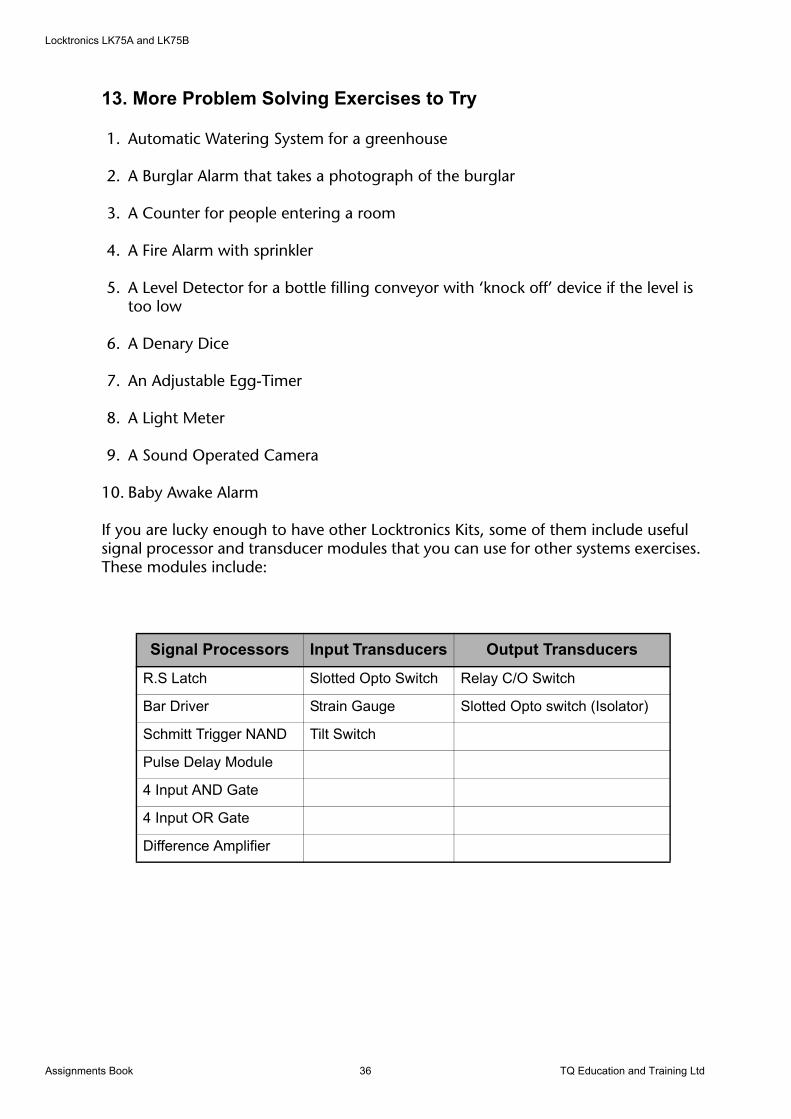
13. More Problem Solving Exercises to Try
1. Automatic Watering System for a greenhouse
2. A Burglar Alarm that takes a photograph of the burglar
3. A Counter for people entering a room
4. A Fire Alarm with sprinkler
5. A Level Detector for a bottle filling conveyor with ‘knock off’ device if the level is too low
6. A Denary Dice
7. An Adjustable Egg-Timer
8. A Light Meter
9. A Sound Operated Camera
10. Baby Awake Alarm
If you are lucky enough to have other Locktronics Kits, some of them include useful signal processor and transducer modules that you can use for other systems exercises. These modules include:
Signal Processors Input Transducers Output Transducers
R.S Latch Slotted Opto Switch Relay C/O Switch
Bar Driver Strain Gauge Slotted Opto switch (Isolator)
Schmitt Trigger NAND Tilt Switch
Pulse Delay Module
4 Input AND Gate
4 Input OR Gate
Difference Amplifier
Assignments Book 36 TQ Education and Training Ltd
Locktronics LK75A and LK75B
Appendix
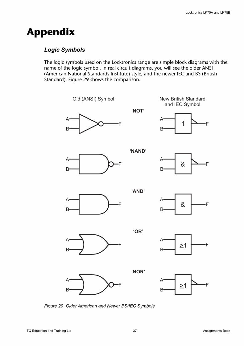
Logic Symbols
The logic symbols used on the Locktronics range are simple block diagrams with the name of the logic symbol. In real circuit diagrams, you will see the older ANSI (American National Standards Institute) style, and the newer IEC and BS (British Standard). Figure 29 shows the comparison.
Figure 29 Older American and Newer BS/IEC Symbols
‘NOT’
BF
A
‘AND’
BF
A
‘OR’
BF
A
‘NOR’
BF
A
‘NAND’
BF
A
B
AF
B
AF
B
AF
B
AF
B
AF
1
&
&
>1
>1
Old (ANSI) Symbol New British Standardand IEC Symbol
TQ Education and Training Ltd 37 Assignments Book
Locktronics LK75A and LK75B
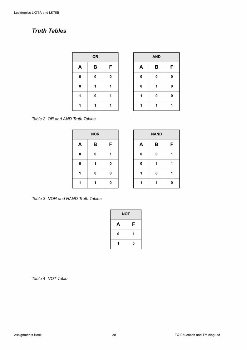
Truth Tables
Table 2 OR and AND Truth Tables
Table 3 NOR and NAND Truth Tables
Table 4 NOT Table
OR AND
A B F A B F
0 0 0 0 0 0
0 1 1 0 1 0
1 0 1 1 0 0
1 1 1 1 1 1
NOR NAND
A B F A B F
0 0 1 0 0 1
0 1 0 0 1 1
1 0 0 1 0 1
1 1 0 1 1 0
NOT
A F
0 1
1 0
Assignments Book 38 TQ Education and Training Ltd