lightweighting of a hydrogen fuel cell vehicle whilst
TRANSCRIPT
EVS27 Electric Vehicle Symposium 1
EVS27
Barcelona, Spain, November 17-20, 2013
Lightweighting of a Hydrogen Fuel Cell Vehicle Whilst
Meeting Urban Accident Criteria
O. Grimes1, C. Bastien
1, J. Christensen
1, N. Rawlins
1, W. Hammond
1, P. Bell
1,
B. Brown1,
J. Beal1
1Coventry University, Priory street, Coventry CV1 5FB, [email protected]
Abstract
The aim of this paper is to assess the safety performance of a lightweight hydrogen fuel cell city concept
vehicle entitled Microcab [1]. The Microcab is a lightweight 4 seat hydrogen fuel cell concept vehicle with
a combined mass (excluding passengers) of less than 800kg. The Microcab has a range of 180 miles; it
includes a hydrogen fuel tank pressurised to 350 bar. The research focuses on urban accident scenarios;
including frontal, lateral and compatibility loadcases. All loadcases utilise urban speeds, i.e. speeds ranging
up to 40km/h for frontal impacts.
The crashworthiness of the Microcab has been analysed using explicit non-linear Finite Element Analysis
(FEA). The study concludes that within the limitations of the material parameter definitions and mass
distributions; the crashworthiness in connection with urban accident scenarios is good. This includes
aspects such as vehicle compatibility loadcases and protection of the hydrogen fuel tank e.g. for intrusion.
The outcome of the study also suggests structural refinements for the future Microcab final production
model; with an aim of further improving the vehicles’ crashworthiness. These refinements include raising
the primary front crash structure to better align it with that of a Sports Utility Vehicle (SUV) as well as
bracing the fuel cell area in case of a rear impact in order to better protect this vital component. It is also
suggested that adhesive joints were suitable for structural crash integrity in all the loadcases studied within
this paper, including low speed impact for repairability.
A structural optimisation study has also been undertaken utilising Design Of Experiments (DOE), shape-
size- and topology optimisation. DOE was employed to further improve the stiffness of the chassis with
respect to safety, whilst minimising the mass increase. Topology optimisation models based on the
maximum crash force magnitudes computed in the initial part of the study were also setup; the results of
these suggested future changes to the Microcabs’ floor layout could be utilised to further enhance the
vehicles crashworthiness.
Keywords: EV, Hydrogen Fuel Cell, crashworthiness, Optimisation, Topology
EVS27 Electric Vehicle Symposium 2
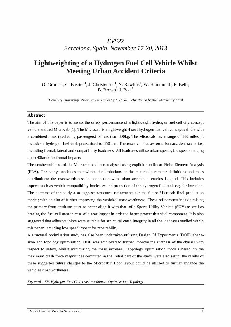
1 Introduction The aim of this paper is to assess the safety
performance of a lightweight hydrogen fuel cell
city concept vehicle entitled Microcab [1]. The
Microcab, illustrated in Figure 1, is a lightweight
4 seat hydrogen fuel cell concept vehicle with a
combined mass (excluding passengers) of less
than 800kg. The Microcab has a range of 180
miles; it includes a hydrogen fuel tank
pressurised to 350 bar.
Figure 1: Microcab. Concept Lightweight Hydrogen
Fuel Cell Vehicle
The Microcab prototype chassis has previously
been studied in isolation. The study documented
by this paper did however include the full detail
of the vehicle, including e.g. door and body
panels. This increased level of detail enabled a
significantly increased understanding of the
possibilities for further light-weighting of the
vehicle ahead of a future commercial production
of the Microcab.
The future hydrogen fuel cell vehicle, which will
follow the current Microcab concept vehicle, will
be engineered considering the lightweighting
performance of this prototype whilst further
enhancing the structural integrity of the vehicle.
There are currently no dedicated EuroNCAP test
requirements for such lightweight vehicles and
few obligatory legal requirements for such low
volume productions, hence it was decided that
the safety assessment criteria would be based on
“typical” urban impact scenarios.
2 Vehicle Safety Assessment The purpose of this section is to evaluate the
overall crashworthiness of the current Microcab.
Before this can be completed it was necessary to
define the safety requirements for the Microcab,
or indeed any similar lightweight vehicle
operating in an urban environment. This was
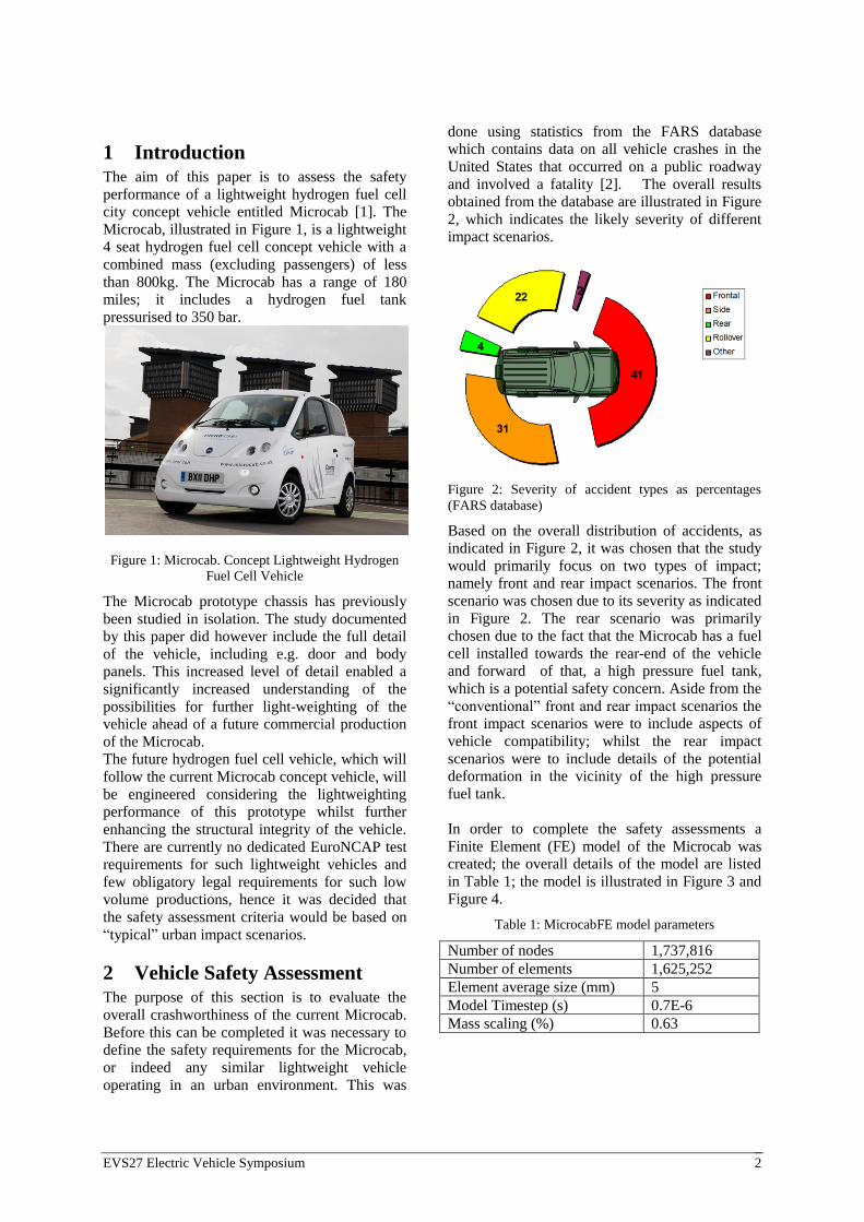
done using statistics from the FARS database
which contains data on all vehicle crashes in the
United States that occurred on a public roadway
and involved a fatality [2]. The overall results
obtained from the database are illustrated in Figure
2, which indicates the likely severity of different
impact scenarios.
Figure 2: Severity of accident types as percentages
(FARS database)
Based on the overall distribution of accidents, as
indicated in Figure 2, it was chosen that the study
would primarily focus on two types of impact;
namely front and rear impact scenarios. The front
scenario was chosen due to its severity as indicated
in Figure 2. The rear scenario was primarily
chosen due to the fact that the Microcab has a fuel
cell installed towards the rear-end of the vehicle
and forward of that, a high pressure fuel tank,
which is a potential safety concern. Aside from the
“conventional” front and rear impact scenarios the
front impact scenarios were to include aspects of
vehicle compatibility; whilst the rear impact
scenarios were to include details of the potential
deformation in the vicinity of the high pressure
fuel tank.
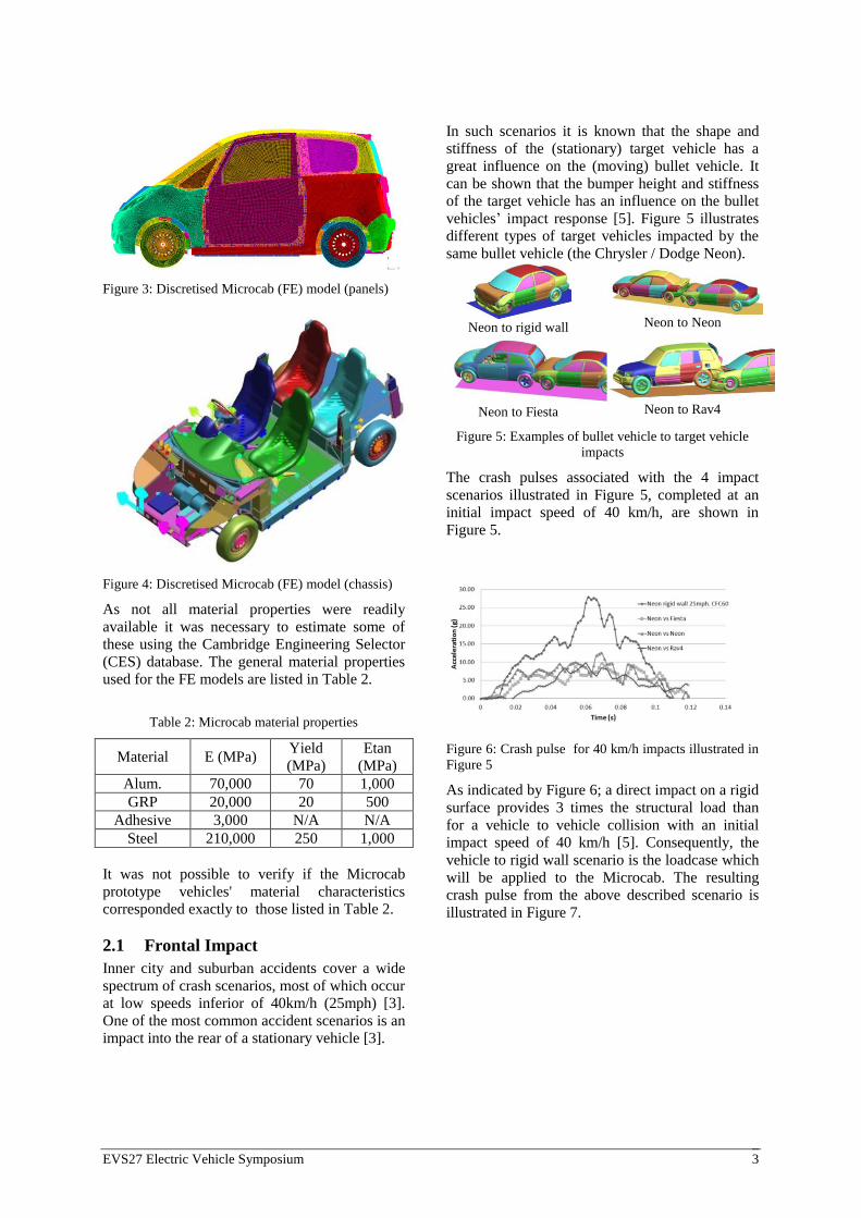
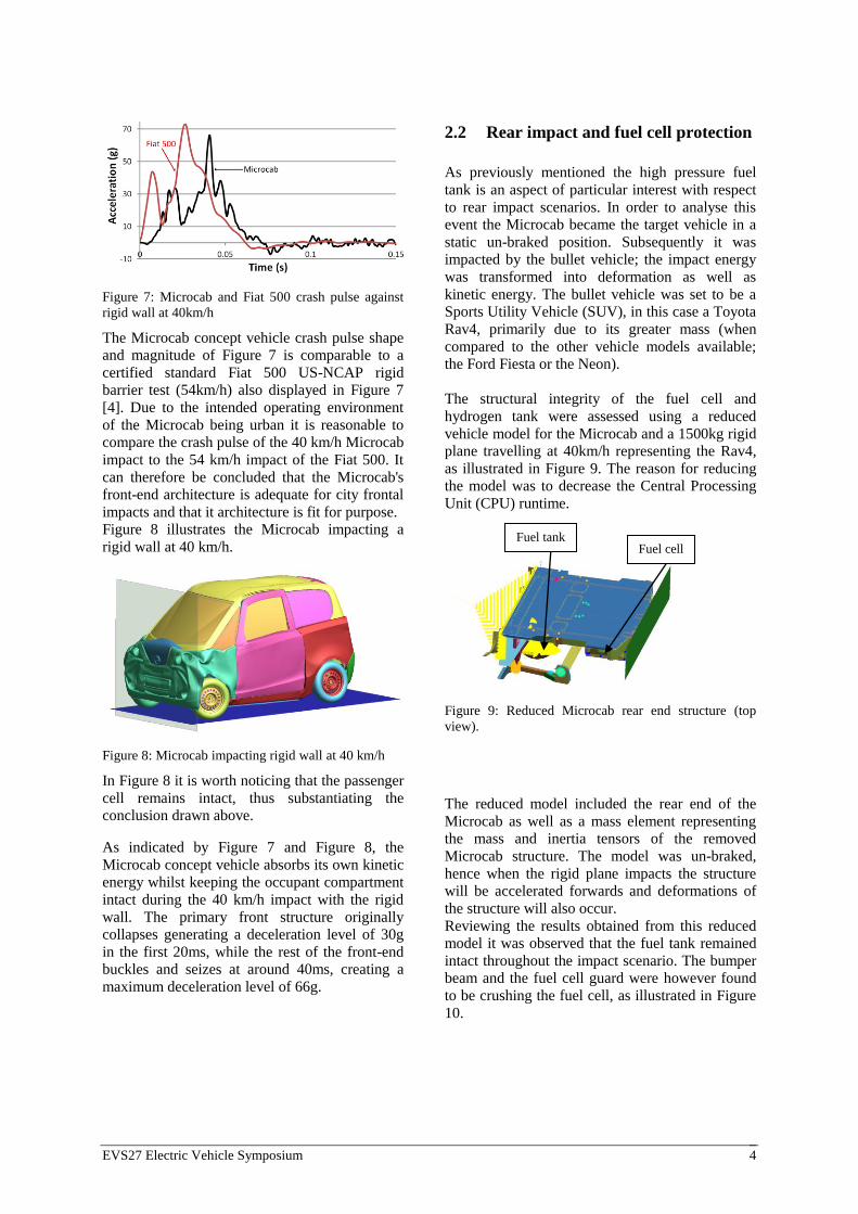
In order to complete the safety assessments a
Finite Element (FE) model of the Microcab was
created; the overall details of the model are listed
in Table 1; the model is illustrated in Figure 3 and
Figure 4.
Table 1: MicrocabFE model parameters
Number of nodes 1,737,816
Number of elements 1,625,252
Element average size (mm) 5
Model Timestep (s) 0.7E-6
Mass scaling (%) 0.63
EVS27 Electric Vehicle Symposium 3
Figure 3: Discretised Microcab (FE) model (panels)
Figure 4: Discretised Microcab (FE) model (chassis)
As not all material properties were readily
available it was necessary to estimate some of
these using the Cambridge Engineering Selector
(CES) database. The general material properties
used for the FE models are listed in Table 2.
Table 2: Microcab material properties
Material E (MPa) Yield
(MPa)
Etan
(MPa)
Alum. 70,000 70 1,000
GRP 20,000 20 500
Adhesive 3,000 N/A N/A
Steel 210,000 250 1,000
It was not possible to verify if the Microcab
prototype vehicles' material characteristics
corresponded exactly to those listed in Table 2.
2.1 Frontal Impact
Inner city and suburban accidents cover a wide
spectrum of crash scenarios, most of which occur
at low speeds inferior of 40km/h (25mph) [3].
One of the most common accident scenarios is an
impact into the rear of a stationary vehicle [3].
In such scenarios it is known that the shape and
stiffness of the (stationary) target vehicle has a
great influence on the (moving) bullet vehicle. It
can be shown that the bumper height and stiffness
of the target vehicle has an influence on the bullet
vehicles’ impact response [5]. Figure 5 illustrates
different types of target vehicles impacted by the
same bullet vehicle (the Chrysler / Dodge Neon).
Neon to rigid wall
Neon to Neon
Neon to Fiesta
Neon to Rav4
Figure 5: Examples of bullet vehicle to target vehicle
impacts
The crash pulses associated with the 4 impact
scenarios illustrated in Figure 5, completed at an
initial impact speed of 40 km/h, are shown in
Figure 5.
Figure 6: Crash pulse for 40 km/h impacts illustrated in
Figure 5
As indicated by Figure 6; a direct impact on a rigid
surface provides 3 times the structural load than
for a vehicle to vehicle collision with an initial
impact speed of 40 km/h [5]. Consequently, the
vehicle to rigid wall scenario is the loadcase which
will be applied to the Microcab. The resulting
crash pulse from the above described scenario is
illustrated in Figure 7.
EVS27 Electric Vehicle Symposium 4
Figure 7: Microcab and Fiat 500 crash pulse against
rigid wall at 40km/h
The Microcab concept vehicle crash pulse shape
and magnitude of Figure 7 is comparable to a
certified standard Fiat 500 US-NCAP rigid
barrier test (54km/h) also displayed in Figure 7
[4]. Due to the intended operating environment
of the Microcab being urban it is reasonable to
compare the crash pulse of the 40 km/h Microcab
impact to the 54 km/h impact of the Fiat 500. It
can therefore be concluded that the Microcab's
front-end architecture is adequate for city frontal
impacts and that it architecture is fit for purpose.
Figure 8 illustrates the Microcab impacting a
rigid wall at 40 km/h.
Figure 8: Microcab impacting rigid wall at 40 km/h
In Figure 8 it is worth noticing that the passenger
cell remains intact, thus substantiating the
conclusion drawn above.
As indicated by Figure 7 and Figure 8, the
Microcab concept vehicle absorbs its own kinetic
energy whilst keeping the occupant compartment
intact during the 40 km/h impact with the rigid
wall. The primary front structure originally
collapses generating a deceleration level of 30g
in the first 20ms, while the rest of the front-end
buckles and seizes at around 40ms, creating a
maximum deceleration level of 66g.
2.2 Rear impact and fuel cell protection
As previously mentioned the high pressure fuel
tank is an aspect of particular interest with respect
to rear impact scenarios. In order to analyse this
event the Microcab became the target vehicle in a
static un-braked position. Subsequently it was
impacted by the bullet vehicle; the impact energy
was transformed into deformation as well as
kinetic energy. The bullet vehicle was set to be a
Sports Utility Vehicle (SUV), in this case a Toyota
Rav4, primarily due to its greater mass (when
compared to the other vehicle models available;
the Ford Fiesta or the Neon).
The structural integrity of the fuel cell and
hydrogen tank were assessed using a reduced
vehicle model for the Microcab and a 1500kg rigid
plane travelling at 40km/h representing the Rav4,
as illustrated in Figure 9. The reason for reducing
the model was to decrease the Central Processing
Unit (CPU) runtime.
Figure 9: Reduced Microcab rear end structure (top
view).
The reduced model included the rear end of the
Microcab as well as a mass element representing
the mass and inertia tensors of the removed
Microcab structure. The model was un-braked,
hence when the rigid plane impacts the structure
will be accelerated forwards and deformations of
the structure will also occur.
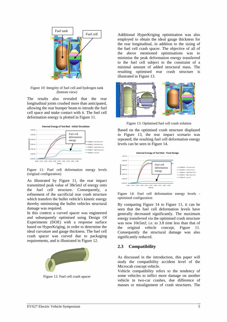
Reviewing the results obtained from this reduced
model it was observed that the fuel tank remained
intact throughout the impact scenario. The bumper
beam and the fuel cell guard were however found
to be crushing the fuel cell, as illustrated in Figure
10.
Fuel cell Fuel tank
EVS27 Electric Vehicle Symposium 5
Figure 10: Integrity of fuel cell and hydrogen tank
(bottom view)
The results also revealed that the rear
longitudinal joints crushed more than anticipated,
allowing the rear bumper beam to intrude the fuel
cell space and make contact with it. The fuel cell
deformation energy is plotted in Figure 11.
Figure 11: Fuel cell deformation energy levels
(original configuration)
As illustrated by Figure 11, the rear impact
transmitted peak value of 38e5mJ of energy onto
the fuel cell structure. Consequently, a
refinement of the sacrificial rear crash structure
which transfers the bullet vehicle's kinetic energy
thereby minimising the bullet vehicles structural
damage was required.
In this context a curved spacer was engineered
and subsequently optimised using Design Of
Experiments (DOE) with a response surface
based on HyperKriging, in order to determine the
ideal curvature and gauge thickness. The fuel cell
crash spacer was curved due to packaging
requirements, and is illustrated in Figure 12.
Figure 12: Fuel cell crash spacer
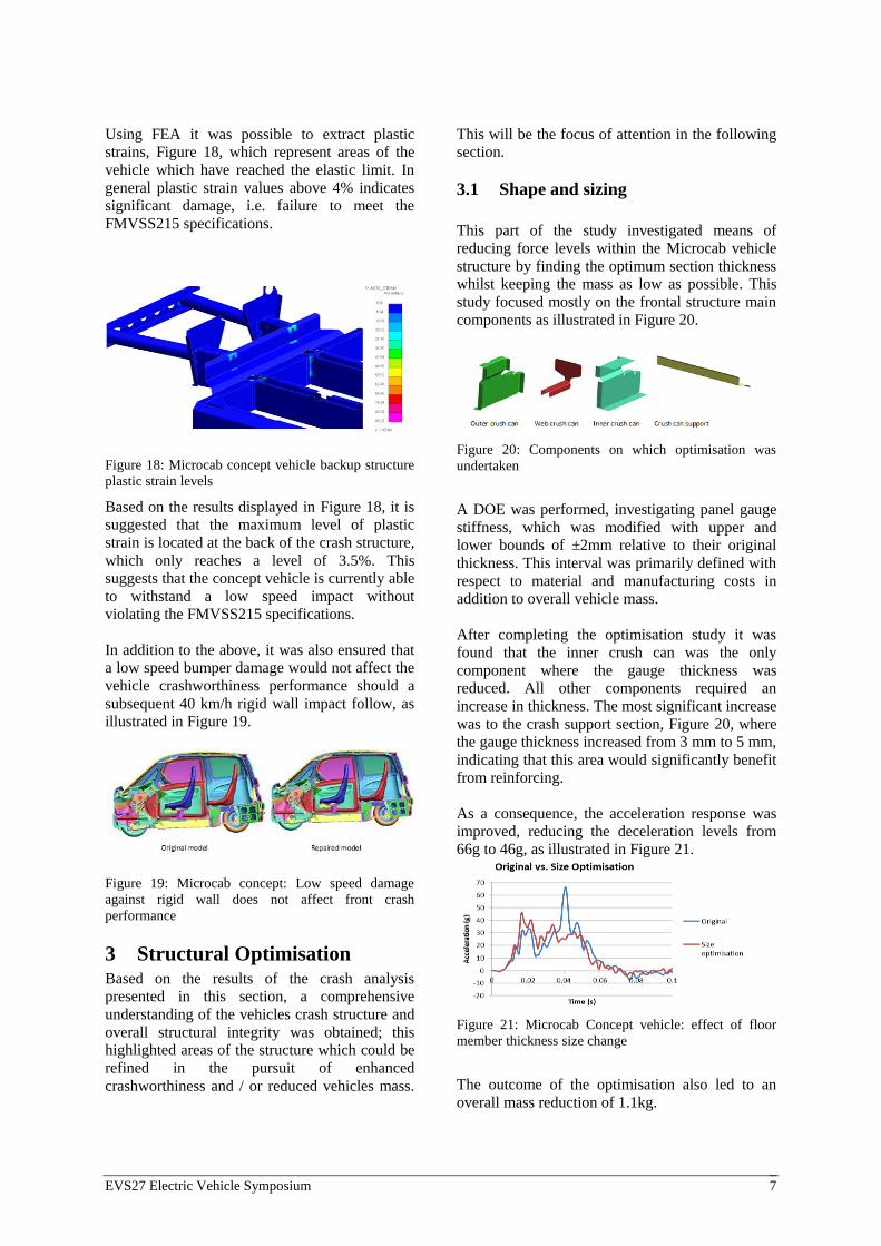
Additional HyperKriging optimisation was also
employed to obtain the ideal gauge thickness for
the rear longitudinal, in addition to the sizing of
the fuel cell crash spacer. The objective of all of
the above mentioned optimisations was to
minimise the peak deformation energy transferred
to the fuel cell subject to the constraint of a
minimal amount of added structural mass. The
resulting optimised rear crash structure is
illustrated in Figure 13.
Figure 13: Optimised fuel cell crash solution
Based on the optimised crash structure displayed
in Figure 13, the rear impact scenario was
repeated; the resulting fuel cell deformation energy
levels can be seen in Figure 14.
Figure 14: Fuel cell deformation energy levels -
optimised configuration
By comparing Figure 14 to Figure 11, it can be
seen that the fuel cell deformation levels have
generally decreased significantly. The maximum
energy transferred via the optimised crash structure
was now 10e5mJ; i.e. to 3.8 time less than that of
the original vehicle concept, Figure 11.
Consequently the structural damage was also
significantly reduced.
2.3 Compatibility
As discussed in the introduction, this paper will
study the compatibility accident level of the
Microcab concept vehicle.
Vehicle compatibility refers to the tendency of
some vehicles to inflict more damage on another
vehicle in two-car crashes, due difference of
masses or misalignment of crash structures. The
Fuel cell
deformation
energy
Fuel cell
deformation
energy
Fuel cell Fuel tank

EVS27 Electric Vehicle Symposium 6
height (from the ground) of the front crash
structure of an SUV is typically larger than that
of a smaller vehicle such as the Microcab. This
misalignment can have a significant effect in the
event of an accident or impact. An example of
this misalignment can be seen in Figure 15,
where the front longitudinals of the Toyota Rav4
are clearly not aligned with those of the
Microcab.
Figure 15: Toyota Rav4 and Microcab concept model
front crash structure misalignment
Assessing the compatibility of a vehicle is not a
legislative requirement, and is not considered in
EuroNCAP testing. Nevertheless, this part of the
paper considers the fuel cell and fuel tank
integrity as well as opportunities of assessing the
integrity of the cabin. Using the UTAC
(Technical Union for the Automobile,
Motorcycle and Cycle industries) Progressive
Deformable Barrier (PDB) for compatibility
assessment (PDB), the aggressiveness of a
vehicle can be found. The aggressiveness of a
vehicle can be interpreted as an expression for
the severity of the structural damage caused
when two vehicles collide in a frontal impact. It
was found that a J segment vehicle such as the
Rav4 was the most aggressive vehicle, whilst the
Microcab was found to have the same level of
aggressiveness as a mid-sized vehicle such as the
Ford Taurus, as indicated by Figure 16.
Figure 16: Comparison of compatibility
aggressiveness
Due to its relatively high level of aggressiveness
the Rav4 was chosen as the bullet vehicle to
impact the Microcab in a frontal impact scenario,
in order to assess the vehicle compatibility with an
impact speed of 40 km/h.
The results of the initial front crash analysis
indicated that the Microcab cabin resisted the
impact from the Rav4, whilst the fuel cell and fuel
tank both remained attached to the main body
structure.
In order to enhance the crash compatibility of the
Microcab concept vehicle the front-end crash
structure was raised by 150mm to better align the
longitudinals with the Rav4, as they were not
initially aligned, as illustrated in Figure 15.
With the height of the front crash structure of the
Microcab increased the front impact scenario with
the Rav4 was repeated, the resulting crash pulse is
illustrated in Figure 17.
Figure 17: Microcab crash pulse before and after
alignment of front crash structure to Rav4.
As indicated in Figure 17, raising the front-end
crash structure of the Microcab suggests a vastly
improved compatibility performance against an
SUV; as the deceleration levels have reduced from
72g to 48g, which is very likely to provide an
improvement of the potential injuries of any
vehicle occupants.
2.4 Damageability
Whereas the previous section considered the
effects of medium to high speed impacts this
section considers the effects of low speed impacts
upon the Microcab structure. The test performed
was an 8 km/h rigid wall test based of the
FMVSS215 [6] specification. This specifies the
parameters of the crash test and stipulates that no
permanent damage on the bumper cover or backup
structure is allowed.
EVS27 Electric Vehicle Symposium 7
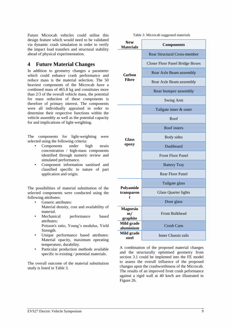
Using FEA it was possible to extract plastic
strains, Figure 18, which represent areas of the
vehicle which have reached the elastic limit. In
general plastic strain values above 4% indicates
significant damage, i.e. failure to meet the
FMVSS215 specifications.
Figure 18: Microcab concept vehicle backup structure
plastic strain levels
Based on the results displayed in Figure 18, it is
suggested that the maximum level of plastic
strain is located at the back of the crash structure,
which only reaches a level of 3.5%. This
suggests that the concept vehicle is currently able
to withstand a low speed impact without
violating the FMVSS215 specifications.
In addition to the above, it was also ensured that
a low speed bumper damage would not affect the
vehicle crashworthiness performance should a
subsequent 40 km/h rigid wall impact follow, as
illustrated in Figure 19.
Figure 19: Microcab concept: Low speed damage
against rigid wall does not affect front crash
performance
3 Structural Optimisation Based on the results of the crash analysis
presented in this section, a comprehensive
understanding of the vehicles crash structure and
overall structural integrity was obtained; this
highlighted areas of the structure which could be
refined in the pursuit of enhanced
crashworthiness and / or reduced vehicles mass.
This will be the focus of attention in the following
section.
3.1 Shape and sizing
This part of the study investigated means of
reducing force levels within the Microcab vehicle
structure by finding the optimum section thickness
whilst keeping the mass as low as possible. This
study focused mostly on the frontal structure main
components as illustrated in Figure 20.
Figure 20: Components on which optimisation was
undertaken
A DOE was performed, investigating panel gauge
stiffness, which was modified with upper and
lower bounds of ±2mm relative to their original
thickness. This interval was primarily defined with
respect to material and manufacturing costs in
addition to overall vehicle mass.
After completing the optimisation study it was
found that the inner crush can was the only
component where the gauge thickness was
reduced. All other components required an
increase in thickness. The most significant increase
was to the crash support section, Figure 20, where
the gauge thickness increased from 3 mm to 5 mm,
indicating that this area would significantly benefit
from reinforcing.
As a consequence, the acceleration response was
improved, reducing the deceleration levels from
66g to 46g, as illustrated in Figure 21.
Figure 21: Microcab Concept vehicle: effect of floor
member thickness size change
The outcome of the optimisation also led to an
overall mass reduction of 1.1kg.

EVS27 Electric Vehicle Symposium 8
By optimising the shape and size of the key
components, Figure 20, it was observed that
neither further mass savings nor significantly
improved crash performance could be obtained,
as the variation of structural mass was minute
whilst the deceleration reduced by a maximum of
3g.
Figure 22: Comparison between pure sizing and
shape/sizing combination
Consequently, should the Microcab concept
vehicle be further optimised it is important to
reconsider the structural loadpaths and
investigate whether or not other means of
channelling the loads through the structure would
be beneficial for the structural performance and
overall efficiency.
3.2 Future topology
The changes suggested in the above section were
obtained using shape and size optimisation. The
results indicated that the changes only had a
minor impact on the crashworthiness of the
Microcab. More drastic measures, and thus more
drastic improvements may be obtained by
utilising topology optimisation to extract
potential vehicle structural loadpaths for a new
Microcab concept vehicle. In order to do this it
was necessary to create a permissible design
volume wherein the loadpaths could be extracted;
this is illustrated in Figure 23 and Figure 24.
Figure 23: Microcab concept chassis design volume
(top view)
Figure 24: Microcab concept chassis design volume
(bottom view)
Creating loadcases representative of the crash
scenarios and the maximum crash pulse obtained
from the FE (crashworthiness) analyses of section
2, the topology optimisation could be completed.
This utilised an isotropic material model and the
Inertia Relief (IR) boundary conditions [7], [8],
[9], [10] and [11] it was possible to extract
suggestions for idealised loadpaths of the future
Microcab vehicle as illustrated in Figure 25.
Figure 25: Optimised Design Volume Comparison
From the optimisation results, Figure 25, it may be
suggested that the front-end of the current
Microcab concept design does not require any
significant modifications.
The centre and rear-end of the chassis looked to be
the areas with the most significant and beneficial
opportunities for redesign with an aim of retaining
the new crashworthiness performance suggested in
this paper, whilst potentially reducing the
structural mass.
This paper has already addressed the rear design
crash protection of the fuel cell, hence future areas
of research would be the chassis floor centre where
it is suggested that most of the load should be
channelled along the vehicle sills and lesser
through the centre of the floor.
Areas of interest
EVS27 Electric Vehicle Symposium 9
Future Microcab vehicles could utilise this
design feature which would need to be validated
via dynamic crash simulation in order to verify
the impact load transfers and structural stability
ahead of physical experimentation.
4 Future Material Changes In addition to geometry changes a parameter
which could enhance crash performance and
reduce mass is the material selection. The 50
heaviest components of the Microcab have a
combined mass of 465.8 kg and constitutes more
than 2/3 of the overall vehicle mass, the potential
for mass reduction of these components is
therefore of primary interest. The components
were all individually appraised in order to
determine their respective functions within the
vehicle assembly as well as the potential capacity
for and implications of light-weighting.
The components for light-weighting were
selected using the following criteria:
• Components under high strain
concentration / high-mass components
identified through numeric review and
simulated performance.
• Component information sanitised and
classified specific to nature of part
application and origin.
The possibilities of material substitution of the
selected components were conducted using the
following attributes:
• Generic attributes:
Material density, cost and availability of
material.
• Mechanical performance based
attributes:
Poisson's ratio, Young’s modulus, Yield
Strength.
• Unique performance based attributes:
Material opacity, maximum operating
temperature, durability.
• Particular production methods available
specific to existing / potential materials.
The overall outcome of the material substitution
study is listed in Table 3.
Table 3: Microcab suggested materials
New Materials
Components
Carbon
Fibre
Rear Structural Cross-member
Closer Floor Panel Bridge Boxes
Rear Axle Beam assembly
Rear Axle Beam assembly
Rear bumper assembly
Swing Arm
Glass
epoxy
Tailgate inner & outer
Roof
Roof inners
Body sides
Dashboard
Front Floor Panel
Battery Tray
Rear Floor Panel
Polyamide
transparen
t
Tailgate glass
Glass Quarter lights
Door glass
Magnesiu
m/ graphite
Front Bulkhead
Mild grade
aluminium Crush Cans
Mild grade
steel Inner Chassis rails
A combination of the proposed material changes
and the structurally optimised geometry from
section 3.1 could be implented into the FE model
to assess the overall influence of the proposed
changes upon the crashworthiness of the Microcab.
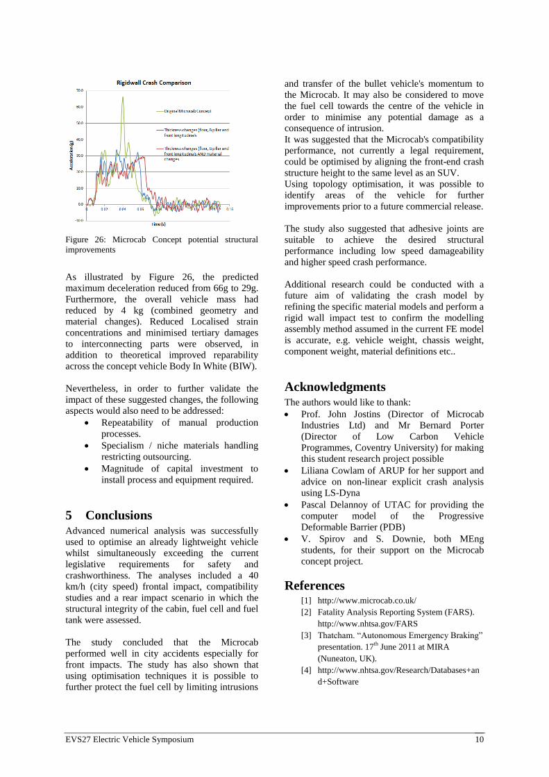
The results of an improved front crash peformance
against a rigid wall at 40 km/h are illustrated in
Figure 26.
EVS27 Electric Vehicle Symposium 10
Figure 26: Microcab Concept potential structural
improvements
As illustrated by Figure 26, the predicted
maximum deceleration reduced from 66g to 29g.
Furthermore, the overall vehicle mass had
reduced by 4 kg (combined geometry and
material changes). Reduced Localised strain
concentrations and minimised tertiary damages
to interconnecting parts were observed, in
addition to theoretical improved reparability
across the concept vehicle Body In White (BIW).
Nevertheless, in order to further validate the
impact of these suggested changes, the following
aspects would also need to be addressed:
Repeatability of manual production
processes.
Specialism / niche materials handling
restricting outsourcing.
Magnitude of capital investment to
install process and equipment required.
5 Conclusions Advanced numerical analysis was successfully
used to optimise an already lightweight vehicle
whilst simultaneously exceeding the current
legislative requirements for safety and
crashworthiness. The analyses included a 40
km/h (city speed) frontal impact, compatibility
studies and a rear impact scenario in which the
structural integrity of the cabin, fuel cell and fuel
tank were assessed.
The study concluded that the Microcab
performed well in city accidents especially for
front impacts. The study has also shown that
using optimisation techniques it is possible to
further protect the fuel cell by limiting intrusions
and transfer of the bullet vehicle's momentum to
the Microcab. It may also be considered to move
the fuel cell towards the centre of the vehicle in
order to minimise any potential damage as a
consequence of intrusion.
It was suggested that the Microcab's compatibility
performance, not currently a legal requirement,
could be optimised by aligning the front-end crash
structure height to the same level as an SUV.
Using topology optimisation, it was possible to
identify areas of the vehicle for further
improvements prior to a future commercial release.
The study also suggested that adhesive joints are
suitable to achieve the desired structural
performance including low speed damageability
and higher speed crash performance.
Additional research could be conducted with a
future aim of validating the crash model by
refining the specific material models and perform a
rigid wall impact test to confirm the modelling
assembly method assumed in the current FE model
is accurate, e.g. vehicle weight, chassis weight,
component weight, material definitions etc..
Acknowledgments The authors would like to thank:
Prof. John Jostins (Director of Microcab
Industries Ltd) and Mr Bernard Porter
(Director of Low Carbon Vehicle
Programmes, Coventry University) for making
this student research project possible
Liliana Cowlam of ARUP for her support and
advice on non-linear explicit crash analysis
using LS-Dyna
Pascal Delannoy of UTAC for providing the
computer model of the Progressive
Deformable Barrier (PDB)
V. Spirov and S. Downie, both MEng
students, for their support on the Microcab
concept project.
References [1] http://www.microcab.co.uk/
[2] Fatality Analysis Reporting System (FARS).
http://www.nhtsa.gov/FARS
[3] Thatcham. “Autonomous Emergency Braking”
presentation. 17th June 2011 at MIRA
(Nuneaton, UK).
[4] http://www.nhtsa.gov/Research/Databases+an
d+Software
EVS27 Electric Vehicle Symposium 11
[5] Bastien C., Blundell M. " Influence of
vehicle secondary impact following an
emergency braking on an unbelted
occupant's neck, head and thorax injuries
International Journal of Crashworthiness",
ICRASH Journal January 2013
[6] http://www.nhtsa.gov/Vehicle+Safety/Test+
Procedures
[7] J. Christensen, C. Bastien, M. V. Blundell,
A. Gittens, O. Tomlin, Topology
Optimisation of a Body In White for Low
Carbon Technology Project , Proceedings of
the European HyperWorks Technology
Conference, Palais de Congres, Versailles,
France, 27th -29
th October 2010.
[8] J. Christensen, C. Bastien, M. V. Blundell,
A. Gittens, O. Tomlin, Lightweight Hybrid
Electrical Vehicle Structural Topology
Optimisation Investigation Focusing on
Crashworthiness, International Journal of
Vehicle Structures and Systems, Volume 3,
Issue 2 2011, pages 113-122.
[9] C. Bastien, J. Christensen, M. V. Blundell,
M. Dickison, A. Gittens, Integration of
Electric Motor and Alternator in Smart
Lightweight Vehicles, Proceedings of the 4th
International Conference on Mechanical
Engineering and Mechanics, Science Press
USA inc., ISBN978-1-933100-40-1, August
2011, pages 921 - 931.
[10] J. Christensen, M. V. Blundell, C. Bastien,
Effects of Roof Crush Loading Scenario
Upon Body In White Using Topology
Optimisation, International Journal of
Crashworthiness, 2011.
[11] J. Christensen, M. V. Blundell, C. Bastien,
Lightweight Body in White Design using
Topology Shape and Size Optimisation,
EVS26, Los Angeles, California, May 2012
[12] J. Christensen, C. Bastien, Generation of
Optimised Hybrid Electric Vehicle Body In
White Architecture from a Styling Envelope,
Global Journal of Researches in Engineering
[13] J. Christensen, M. V. Blundell, C. Bastien,
P. A. Batt, Buckling Considerations and
Cross-Sectional Geometry Development for
Topology Optimised Body In White,
International Journal of Crashworthiness,
2013.
Authors
Oliver Grimes, MSc, BEng, is a
Research Assistant at Coventry
University, working vehicle and seat
lightweighting optimisation. Oliver
has started a PhD on lightweighting
structural optimisation combined
with occupant safety biomechanics.
Christophe Bastien, MSc, BEng
(Hons), CEng, MIMechE, FHEA, is a
principal lecturer and the MSc
Automotive Engineering Programme
Manager at Coventry University. He
has over 15 years of industrial and
academic experience with FEA and
crashworthiness. He is currently
leading the research into the
lightweighting of electrical vehicle
architectures. He has filed 19 patents
in the field of vehicle and highway
engineering safety, and is currently
undertaking a PhD in occupant
biomechanics
Jesper Christensen, MSc, BSc,
CEng, MIMechE, FHEA, is a
Lecturer in Stress Analysis at
Coventry University. The past 3
years of his career has been spent
focusing on structural optimisation in
connection with crashworthiness,
primarily in relation to HEV
vehicles, for which he has published
several recent papers. He is currently
undertaking a PhD within the field of
structural optimisation.
Nicholas Rawlins, Part time MEng
student at Coventry University.
Nicholas is employed by PLastic
Omnium and expcted to complete his
studies in September 2014.
William Hammond, is a full time
MEng student at Coventry
University. William will graduate in
June 2013.
EVS27 Electric Vehicle Symposium 12
Peter Bell, is a full time MEng
student at Coventry University.
Peter will graduate in June 2013.
Ben Brown, is a full time MEng
student at Coventry University.
Ben will graduate in June 2013.
Jonathan Beal, is a full time
MEng student at Coventry
University. Jonathan will
graduate in June 2013.