fy2003 progress report for automotive lightweighting materials · fy 2003 progress report...
TRANSCRIPT

Automotive Lightweighting Materials FY 2003 Progress Report
����"%7"/$&%�."5&3*"-4�%&7&-01.&/5�
"�� -PX�$PTU�1PXEFS�.FUBMMVSHZ�GPS�1BSUJDMF�3FJOGPSDFE�5JUBOJVN�"VUPNPUJWF� $PNQPOFOUT��
Russell A. Chernenkof Ford Motor Company SRL MD3135 2101 Village Road, Dearborn, MI 48124 (313) 594-4626; e-mail: [email protected]
Dr. William F. Jandeska General Motors Corporation, GM Powertrain 895 Joslyn Ave. Pontiac, MI 48340 (248) 857-2184; e-mail: [email protected]
Dr. Jean C. Lynn DaimlerChrysler 800 Chrysler Dr. East, CIM484-01-13, Auburn Hills, MI 48326 (248) 576-3192; e-mail: [email protected]
Technology Area Development Manager: Joseph A. Carpenter (202) 586-1022; fax: (202) 586-1600; e-mail: [email protected] Field Technical Manager: Philip S. Sklad (865) 574-5069; fax: (865) 576-4963; e-mail: [email protected]
Contractor: U.S. Automotive Materials Partnership Contract No.: DE-FC05-02OR22910
0CKFDUJWF�
• Demonstrate production-intent process scheme and fully densified titanium alloy powder metallurgy (PM) composite samples.
• Benchmark process capability using commercial-grade titanium powder feedstock, and follow with one of the proposed low-cost titanium powder materials. Blend additives to achieve final titanium alloy material with reinforcement.
• Perform microstructure characterization and interfacial studies.
• Confirm test specimens are crack-free by nondestructive evaluation method (Lawrence Livermore National Laboratory).
• Generate static mechanical properties and perform failure analysis.
• Perform a technical cost modeling study on the novel ADMA Products, Inc., process andestablish sensitivity of each processing step for cost-effectiveness.
49
FY 2003 Progress Report Automotive Lightweighting Materials
"QQSPBDI�
• Use titanium metal feedstock to produce blanks in simple shapes via the ADMA manufacturing process that will then be machined into coupons for mechanical property determination.
• Conduct microstructural and interfacial studies together with mechanical property testing by the team, including outside sources jointly selected.
• Preform a technical cost model on the ADMA manufacturing process.
"DDPNQMJTINFOUT�
• Held project "kick-off" meeting at ADMA Products, Inc., on August 27, 2003.
• Purchased and received all raw materials required for the program.
• Produced and die pressed various powder blends in 0.500-in.-diam carbide tooling to 0.500-in. thickness for metallographic examination.
• Compacted powder blends into 3- by 5-in. samples for tensile testing.
• Continued metallographic examination.
'VUVSF�%JSFDUJPO�
• Complete microstructure characterization and interfacial studies.
• Complete mechanical testing and failure analysis.
• Complete a final report on the feasibility study by October 31, 2004.
&YFDVUJWF�4VNNBSZ�
The goal of this concept feasibility study is to develop a low-cost PM manufacturing process to obtain fully dense parts based on current commercial-grade materials and a novel processing technology. The study will use particle-reinforced titanium metal feedstock in conjunction with PM press and sinter technology to manufacture simple
parts for testing. A technical cost model will be performed to document the cost of the manufacturing process. The decision gate criteria are (1) a cost-competitive manufacturing process and (2) acceptable microstructure and mechanical properties that have been identified for connecting rods targeted for high-performance reciprocating engine applications.
50

Automotive Lightweighting Materials FY 2003 Progress Report
#���-PX�$PTU�$BTU�"MVNJOVN�.FUBM�.BUSJY�$PNQPTJUFT�
Principal Investigator: Darrell R. Herling Pacific Northwest National Laboratory P.O. Box 999, K2-03, Richland, WA 99352 (509) 376-3892; fax: (509) 376-6034; e-mail: [email protected]
Technology Area Development Manager: Joseph A. Carpenter (202) 586-1022; fax: (202) 586-1600; e-mail: [email protected] Field Technical Manager: Philip S. Sklad (865) 574-5069; fax: (865) 576-4963; e-mail: [email protected]
USCAR Project Steering Committee: Bruce Cox DaimlerChryslerG (248) 576-0235; fax: (248) 576-7288; e-mail: [email protected] Rena Hetcsh Ford Motor CompanyG (313) 322-9079; fax: (313) 390-0514; e-mail: [email protected] James Quinn General MotorsG (586) 986-6712; fax: (586) 986-9204; e-mail: [email protected]
Contractor: Pacific Northwest National Laboratory Contract No.: DE-AC06-76RL01830
0CKFDUJWF�
• Develop low-cost aluminum metal matrix composite (MMC) materials that are cost competitive with typical aluminum alloys used in the automotive industry.
• Provide lightweight, cost-effective aluminum MMC material options for powertrain and structural automotive applications for future vehicles.
• Develop a modular compositing (mixing and holding) system for the production of low-cost aluminum MMC materials. This portion of the effort was conducted under a cost-shared contract with MC-21, Inc., Carson City, Nevada, which has successfully been completed with the results exceeding expectations.
• Identify, evaluate, and develop, as necessary, economic innovative casting and finishing technologies to produce aluminum-MMC automotive brake system components.
"QQSPBDI�
• Develop rapid MMC mixing process and lower-cost, castable aluminum MMC material.
• Evaluate mechanical and physical properties, as well as castability of this material.
• Friction- and wear-test sample products produced from the low-cost MMC material.
• Explore innovative casting and finishing options.
• Design innovative brake system to utilize aluminum MMC materials.
• Prototype and full-scale test demonstration component (brake rotor).
• Optimize finishing technologies for cost-effective aluminum MMC components.
51

FY 2003 Progress Report Automotive Lightweighting Materials
"DDPNQMJTINFOUT�
• Completed the design and analysis of a brake rotor geometry designed specifically for aluminum MMC materials (Visteon-led activity).
• Transferred this innovative brake rotor design to THT Presses, Dayton, Ohio, for casting die design and fabrication in preparation for prototype brake rotor casting.
• Completed casting trials and process parameter development for full-scale component.
• Completed postprocessing (heat treating and machining) study of prototype brake rotors.
• Prototyped new brake rotors for evaluation.
• Validated the function of the close-die tooling and modified squeeze casting cycle process.
• Evaluated and approved prototype microstructure and mechanical properties.
• Completed initial phase of brake rotor dynamometer testing to determine performance and validate modeling results.
'VUVSF�%JSFDUJPO�
• Commence study on proper finishing methods and economics for automotive aluminum MMC components.
• Evaluate economy of centrifugal casting for large-volume production of aluminum components.
• Prototype selectively reinforced aluminum MMC brake rotors and conduct subsequent testing for comparison to the fully reinforced prototype pieces.
• Investigate the use of centrifugal casting to demonstrate the production of a selectively reinforced brake rotor caliper with the reinforcement located in the bridge region of the caliper (PNNL).
*OUSPEVDUJPO�
The objectives of this project are (1) to provide lightweight, cost-competitive aluminum MMC options for future cars, sport utility vehicles (SUVs), and hybrid vehicles and (2) to demonstrate these developments on prototype brake system components such as a lightweight brake rotors. The approach is to develop advanced MMC material processing technologies and integrate these processes into an economical manufacturing cycle (i.e., low-cost material plus innovative shape casting plus low finishing cost), including consideration of product design that accounts for material-specific manufacturing characteristics and component performance.
In the first phase of the project, a novel mixing process was developed for the
economical production of aluminum MMC materials under a cost-shared industrial contract with MC-21, Inc. This proprietary process rapidly mixes reinforcement particulate into the matrix alloy, by utilizing a specially designed mixing head that is rotated at high speeds. The process can produce aluminum MMC material for $1/lb, which is a significant cost savings of greater than 50% over other similar commercial products. This is a significant enabler for the automotive industry to utilize wear-resistant, high specific strength and stiffness MMC components.
In addition to reducing the production costs associated with MMC materials, innovative shape casting processes were evaluated for manufacturing aluminum MMCs. The general approaches investigated (depicted in
52

Automotive Lightweighting Materials
Figure 1) represent conventional casting methods as well as methods designed to produce selectively reinforced structures.
The objective of the final phase of this project is to demonstrate the benefits of lightweight aluminum MMC components by applying the low-cost MMC material to a brake rotor in an appropriate manner. The approach is to develop a novel brake rotor design that will properly utilize and exploit the properties of aluminum MMCs for high-friction and wear applications. Prototype castings of full-scale brake rotors are to be produced in order to be tested for performance and durability of the rotor design and MMC material under simulated vehicle operating conditions.
*OOPWBUJWF�#SBLF�3PUPS�%FTJHO �1SPUPUZQJOH �
BOE�5FTUJOH�
A collaboration with Visteon Chassis Systems, Dearborn, Michigan, was initiated to design a brake rotor geometry utilizing aluminum MMC materials for construction. Instead of taking a direct materials substitution approach using a conventional cast iron brake rotor design, which has been tried in
FY 2003 Progress Report
the past with poor results, the goal was to create a new design geometry that can exploit the properties of an aluminum MMC material with good thermal performance. With this approach, Visteon has developed a functional aluminum MMC brake rotor that can be used for both front and rear brake rotors of a typical midsize passenger vehicle. Visteon used computational fluid dynamic (CFD) simulations to help create the novel brake rotor design, using the materials properties provided by PNNL for the low-cost aluminum-MMC material. In addition, finite-element analysis (FEA) of the rotor was performed for this design to ensure that the stress levels in the rotor due to thermal gradients and braking loads were acceptable. Based on the modeling results, it was determined that the design should work well for a midsize sedan, even under severe and repeated stopping conditions without overheating. A solid-model representation of the innovative brake rotor design is shown in Figure 2.
THT Presses, Dayton, Ohio, was contracted under a 50/50 cost share agreement to design and fabricate closed-die casting tooling to produce full-scale prototypical
Figure 1. Processing routes investigated for the production of an aluminum MMC brake rotor.
53

FY 2003 Progress Report
Figure 2. Solid model designed by Visteon specifically for aluminum MMC brake rotors; U.S. Patent No. 6,536,564.
rotors using the rotor design provided by Visteon. The new brake rotor design was transferred from Visteon to THT where casting molds were produced. Subsequent casting trials and die calibrations were performed to achieve the desired rotor casting tolerances. The material selected for these prototypes was produced by MC-21, Inc., using the low-cost 359/SiC/20p material made with the Rapid Mixing Technology developed earlier in the project.
The first round of prototype casting trials produced castings of poor quality, as shown in Figure 3(a). During a review by PNNL of the casting quality and process, it was
Automotive Lightweighting Materials
revealed that mold filling and liquid-metal handling issues led to the casting defects and particle segregation. David Weiss, Eck Industries, and PNNL provided a technical review and suggestions on better melting and casting practices for MMC materials. In addition, modifications to the mold gating area were employed, which significantly enhanced the liquid-metal fill rate in the model. These enhancements to the casting process ultimately led to high-quality castings, as shown in Figure 3(b). The micrograph in Figure 4 is representative of the casting quality and good particle distribution produced using this modified squeeze casting method. This iteration of the casting parameters demonstrates the importance of using an optimized casting practice for aluminum MMC materials that is specifically developed with considerations for material properties and casting mold design.
A total of 48 prototype rotor castings were produced and then heat treated to T71 condition. Figure 4 shows one of the prototype brake rotors in cast form, as well as the representative microstructure and particle distribution of these parts. These rotors were machined at the direction of Visteon and then tested by Link Engineering on a brake dynamometer, utilizing industry standard test protocols for evaluation of disc brake rotor performance. The specified test
Figure 3. (a) Particle segregation and porosity that developed during poor MMC casting practices. (b) Appropriate melting and metal handling practices for MMCs, producing high-quality castings with the expected microstructure.
54

Automotive Lightweighting Materials FY 2003 Progress Report
Figure 4. Prototype brake rotor cast from low-cost aluminum MMC material and utilizing a new rotor geometry. The micrograph is representative of the casting microstructure and particle distribution.
schedule called for a variety of different drive and braking conditions and cycles, including tests for: (1) brake thermal performance; (2) simulation of Laurel Mountain hot roughness brake; (3) lining wear vs temperature; (4) environmental brake noise tests (with steady drag); (5) disc wear with low-pressure drag; and (6) brake effectiveness. The results of the dynamometer testing are given in Table 1.
$FOUSJGVHBM�$BTUJOH�&WBMVBUJPO�
There are many known technical benefits to centrifugal casting MMCs for the production of selectively reinforced axisymmetric components, such as high material yield, less casting cleaning requirements, locating high-performance particles where they have the most benefit, higher toughness of unreinforced areas, and easier machining require
ments. However, there is very little known about the economics of this process for medium- or large-scale manufacturing, especially for aluminum-based materials. Although the technology of centrifugal casting MMCs has been demonstrated successfully in low-volume applications, there are no data of casting equipment for automotive component production. Some of the expected issues that need to be addressed include potentially long cycle times and adequate control of mold temperature and fill rates.
PNNL, in conjunction with Eck Industries, has initiated a study to investigate the economics of centrifugal casting for MMC brake rotors. The scope of this study includes designing and building tooling to demonstrate viability of “production” type
Table 1. Results of prototype brake dynamometer testing
Test description Pass/fail
Dyno simulation of AMS and fade test Pass
Dyno simulation of Laurel Mountain hot roughness brake test Pass
Brake lining wear vs temperature test Pass
Brake noise test (with steady drag) Pass
Disc wear test (with low-pressure drag) Pass
Brake effective test Pass
55

FY 2003 Progress Report
centrifugal casting machines to cast MMCs as well as developing production parameters for the production of MMC rotor castings. This information will provide the necessary data to qualify rotors produced using centrifugal casting and will indicate whether it will be a valid commercial process for MMC automotive components.
'VUVSF�8PSL�
Additional dynamometer evaluations of full-scale rotors will be conducted at Link Engineering in the first quarter of FY 2004, and they will be performed with alternative brake pad chemistries. A progress report documenting the outcome of the evaluation and performance of fully reinforced rotors will be drafted and disseminated to the project team and the steering committee. The technical cost model originally developed will be revised based on new cost
Automotive Lightweighting Materials
information from the prototyping phase of the project. Likewise, cost data will be revised as a result of the study to evaluate the commercial validity of centrifugal casting rotor production. This study will also include an evaluation of the need for higher reinforced rotors, or the potential to lower costs by starting with a lower volume fraction feedstock material and using centrifugal casting to achieve a nominal 20 vol % reinforced area.
The remainder of the work scope will focus on prototyping and demonstrating the performance of selectively reinforced aluminum MMC disk brake rotors, instead of the fully reinforced rotors. In addition, PNNL will investigate the use of centrifuge casting to demonstrate the production of a selectively reinforced brake rotor caliper with the reinforcement located in the bridge region of the caliper.
56

Automotive Lightweighting Materials FY 2003 Progress Report
$���4USVDUVSBM�$BTU�.BHOFTJVN�%FWFMPQNFOU��
Project Chairman: Richard J. Osborne General Motors CorporationMail Code 480-205-314 30007 Van Dyke Road Warren, MI 81033-57039 (586) 575-7039; fax: (586) 492-5115; e-mail: [email protected]
Project Administrator: D.E. Penrod P.E. Manufacturing Services and Development, Inc. 4665 Arlington DriveCape Haze, Florida 33946 (941) 697-5764; fax: (941) 697-5764; e-mail: [email protected]
Technology Area Development Manager: Joseph A. Carpenter(202) 586-1022; fax: (202) 586-1600; e-mail: [email protected] Field Technical Manager: Philip S. Sklad (865) 574-5069; fax: (865) 576-4963; e-mail: [email protected]
Contractor: U.S. Automotive Materials Partnership Contract No.: DE-FC05-020R22910
0CKFDUJWF�
• Develop the science and technology necessary to implement a front structural cradle (from two different magnesium casting processes) that will interface with other concurrent magnesium programs proposed for the U.S. automotive industry.
"QQSPBDI�
• Improve our scientific understanding of magnesium alloys.
• Develop a cost model that compares cast magnesium chassis component costs to other materials and processing techniques.
• Provide comprehensive database and design guidelines.
• Develop improved casting processes.
• Identify and/or develop methods to improve corrosion resistance.
• Improve joining technologies.
• Transfer knowledge and lessons learned to industry.
• Obtain all of the scientific parts of the project that are required [microstructure; effects of modeling; corrosion and fastening properties, nondestructive evaluation (NDE) methods etc.].
• Convert an existing aluminum cradle to magnesium and to have parts ready for testing, and approved for Corvette’s Job 1 for 2006. Therefore, the industry part of this project cannot wait for all of the intricate scientific parts of the project to be understood—before a process is chosen; tooling built; parts cast and the validation tests to be run. However, both aspects of the project must be constantly aware of the each other’s needs and progress, as shown in Figure 1.
57

FY 2003 Progress Report Automotive Lightweighting Materials
Figure 1. Dual-project path for science and magnesium prototype casting validation activities.
"DDPNQMJTINFOUT�
• Expanded the development of the magnesium alloy database.
• Expanded the collection of magnesium alloy castings for the development of the database.
• Developed magnesium cradle casting parameters for both magnesium casting processes.
• Started durability testing procedures for one of the castings selected from one of the casting processes.
• Expanded the corrosion and casting protection evaluation for specific cradle connectors.
• Started the investigation of in-mold sensor applications.
• Continued the characterization of AM50 High-Pressure Die Cast Alloy by Georgia Institute of Technology
'VUVSF�%JSFDUJPO�
• Start the rigorous bench tests of both Corvette cradle designs. If acceptable, one design will be installed on a vehicle for actual road tests. There is a potential market for 35,000 vehicles for Job 1 for 2006.
• Follow the Structural Cast Magnesium Development (SCMD) Project’s Statement of Work Tasks to complete the project on time, including both the scientific and manufacturing aspects of the project.
• Continue to work with the industrial participants with the development of sensors and practical applications developed by the SCMD project.
58

Automotive Lightweighting Materials
*OUSPEVDUJPO�
The SCMD project has focused on resolving critical issues that limit the large-scale application of magnesium castings in automotive components. The project activities combine the science and manufacturing technology necessary to implement front and rear structural cradles. Such components offer all of the difficult manufacturing issues, including casting process (high-pressure die, semisolid, low pressure, squeeze, etc) and joining, along with harsh service environment challenges, such as corrosion, fatigue, and stress relaxation associated with fasteners.
The project team includes personnel from • the “Big Three” automotive companies, • 34 companies from the casting supply
base, • academic personnel,
FY 2003 Progress Report
• independent testing and research labs, • American Foundry Society (AFS), • technical associations, • Oak Ridge National Laboratory (ORNL), • Sandia National Laboratory (SNL), • Lawrence Livermore National Laboratory
(LLNL), and • Natural Resources Canada (CANMET).
*OEVTUSZ�1BSUJDJQBOUT�
An existing aluminum engine cradle (that is currently in production use) has been redesigned for two different magnesium casting processes: High-Pressure Die Casting (HPDC) and Low-Pressure Permanent Mold (LPPM). Utilization of computer simulations (prior to tooling design) indicated good correlation of casting fill operation (and their effects) to actual production experiences (see Figure 2).
Figure 2. EKK, Inc. cavity fill simulations show excellent correlation with short fill castings.
59

FY 2003 Progress Report Automotive Lightweighting Materials
Tools have been built for both processes, and preliminary prototype castings have been submitted for review (see Figure 3). Durability and other related tests are scheduled for the testing of both cradle designs. A selection will then be made to meet the timing date of Job 1 for the 2006 production year. • Importance/Significance: Utilization of
up-front computer modeling resulted in significant savings (time and costs) and eliminating casting defects in the initial castings.
There is an estimated 35% weight saving in the magnesium cradle vs the current aluminum production part. This weight reduction (vehicle mass savings) will result in a reduction in fuel consumption, emissions and less dependence on foreign oil. Cast magnesium structures have the potential to reduce 100 kg of vehicle mass, which could reduce emissions by 5% and reduce fuel consumption by approximately 1.0 mpg (ignoring secondary mass savings).
The investigation of producing the same casting by the two different processes (HPDC and LPDC) has a great potential for the utilization of existing aluminum casting companies to expand their operations into magnesium, without huge capital and facility expenditures.
Figure 3. Initial machined HPDC magnesium cradle, August 20, 2003.
/BUJPOBM�-BCPSBUPSZ�1BSUJDJQBOUT�
• ORNL is investigating the effects of using die lube for HPDC and LPDC operations.
Importance/Significance: The investigation has already indicated that gas can be generated from the lube when molten metal (higher temperature) is introduced into the mold cavity. The gas then disperses throughout the casting, causing various types of porosity defects.
• LLNL is investigating the utilization of sensors in casting molds and the effects of impurities in material supplied by manufacturing plants (see Figure 4).
Importance/Significance: Utilization of sensors will provide a more accurate report and understanding of the actual process parameters within the casting mold. Investigation and possible elimination of impurities in the metal charged into the furnace will reduce defects.
• SNL is expanding a “failure model” that was designed for the previously completed Cast Light Metals (CLM) project. SNL is coordinating all of information obtained from the project, and a mathematical model will be developed (see Figure 5).
Importance/Significance: Designers can use the model to develop castings, with the accurate knowledge of providing know failure points.
• Academia participants: Academia participation is involved with the investigation of and characteriza
tion of crack nucleation and growth; and
the investigation into the cause of casting defects and the ability to separate gas and shrinkage effects that are generated in the casting by the various processes and the resulting defects that can be generated (see Figure 6).
Importance/Significance: The importance of understanding the crack
60

Automotive Lightweighting Materials FY 2003 Progress Report
Figure 4. LLNL development activities.
Figure 5. SNL damage model for simulating component material properties.
61

FY 2003 Progress Report Automotive Lightweighting Materials
Figure 6. Georgia Institute of Technology characterization of AM50 HPDC alloy.
nucleation and the results of gas generated in magnesium castings willhelp to provide tools to manufacturing(or change process parameters) that willhelp to eliminate casting defects. Both ofthese investigations by academia are working with the information supplied by ORNL and sample parts provided by the manufacturing team. The understanding of the gas effects incastings, generated by die lube could be a major breakthrough in understanding defects in magnesium castings.
market for 35,000 vehicles for Job 1 for 2006.
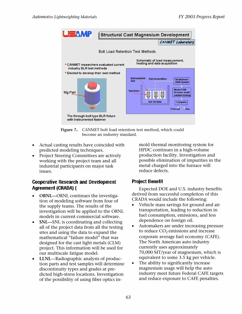
2. An investigation is ongoing into the effects of corrosion, coatings, and protection; long-range effects of bolt load retention are all being studied by CANMET (see Figure 7). Similar magnesium production parts have been prepared and sent to Newfoundland, an area that is recognized for excessive corrosion. These parts are installed on vehicles and currently being studied, and the results will be incorporated into the final design of the magnesium cradle.
1SPKFDU�QSPHSFTT�TUBUVT�WT�UBSHFUT�
Prototype magnesium alloy castings will .JMFTUPOFT�
be provided to the Corvette C6 team before $PPQFSBUJWF�"HSFFNFOU� year end (2003) to coincide with the cradle validation schedule. • Magnesium front cradles have been cast
by both of the chosen magnesium die cast processes.
3FNBJOJOH�5FDIOJDBM�$IBMMFOHFT�BOE�1MBOT� • Detailed quantitative microstructural 1. Corvette will start the rigorous bench
tests of both cradle designs. If acceptable, one design will be installed on a vehicle for actual road tests. There is a potential
characterization continues for production components cast with AM 50, AM 60, and AZ 91 magnesium alloys.
62
Automotive Lightweighting Materials FY 2003 Progress Report
Figure 7� CANMET bolt load retention test method, which could become an industry standard.
• Actual casting results have coincided with mold thermal monitoring system for predicted modeling techniques. HPDC continues in a high-volume
• Project Steering Committees are actively working with the project team and all industrial participants on major task issues.
production facility. Investigation and possible elimination of impurities in the metal charged into the furnace will reduce defects.
$PPQFSBUJWF�3FTFBSDI�BOE�%FWFMPQNFOU� 1SPKFDU�#FOFGJU� "HSFFNFOU�$3"%"� Expected DOE and U.S. industry benefits
• ORNL—ORNL continues the investiga- derived from successful completion of this
tion of modeling software from four of CRADA would include the following:
the supply teams. The results of the • Vehicle mass savings for ground and air
investigation will be applied to the ORNL transportation, leading to reduction in
models in current commercial software. fuel consumption, emissions, and less
• SNL—SNL is coordinating and collecting dependence on foreign oil.
all of the project data from all the testing • Automakers are under increasing pressure
sites and using the data to expand the to reduce CO2 emissions and increase
mathematical “failure model” that was corporate average fuel economy (CAFE). designed for the cast light metals (CLM) The North American auto industry project. This information will be used for currently uses approximately our multiscale fatigue model. 70,000 MT/year of magnesium, which is
• LLNL—Radiographic analysis of produc- equivalent to some 3.5 kg per vehicle. tion parts and test samples will determine • The ability to significantly increase discontinuity types and grades at pre- magnesium usage will help the auto dicted high-stress locations. Investigation industry meet future Federal CAFE targets of the possibility of using fiber optics in- and reduce exposure to CAFE penalties.
63

FY 2003 Progress Report Automotive Lightweighting Materials
Cast magnesium structures have the potential to reduce 100 Kg of vehicle mass, which could reduce emissions by 5% and reduce fuel consumption by approximately 1.0 mpg (ignoring secondary mass savings).
• Light metal alloys have greater recycling value with reduced energy consumption vs plastics (including melting, machining, handling, and transportation energy requirements).
• The Big Three competitive global postures will increase as a result of designing and manufacturing vehicles that offer greater consumer value. This can improve the U.S. trade balance with countries that market higher fuel efficiency vehicles than those produced in North America.
• Health and environmental issues for workers are reduced during light-metal
casting operations when compared to ferrous foundries and polymer molding operations.
• Provide national laboratories with valuable manufacturing development and product application experience.
• Dual-purpose role of providing the national laboratories an opportunity to develop math-based simulation models and NDE technologies that benefit both the auto industry and federal ongoing technology programs.
• The successful casting of a magnesium cradle (by low-pressure diecasting) will indicate to the existing aluminum casting industry that the transfer of casting technology (aluminum to magnesium casting) can be achieved at a low facility cost.
64

Automotive Lightweighting Materials FY 2003 Progress Report
%���.BHOFTJVN�1PXFSUSBJO�$BTU�$PNQPOFOUT�
Project Manager: Bob R. Powell GM Research & Development Center MC 480-106-212, 30500 Mound Road, Warren, MI 48090-9055 (586) 986-1293; fax: (586) 986-9204; e-mail: [email protected]
Project Administrator: Peter Ried Ried & Associates, LLC 6381 Village Green Circle, Suite 10, Portage, MI 49024 (269) 327-3097; fax: (269) 321-0904; e-mail: [email protected]
Technology Area Development Manager: Joseph A. Carpenter (202) 586-1022; fax: (202) 586-1600; e-mail: [email protected] Field Technical Manager: Philip S. Sklad (865) 574-5069; fax: (865) 576-4963; e-mail: [email protected]
Contractor: U.S. Automotive Materials Partnership Contract No.: DE-FC-05-95OR22910
0CKFDUJWF�
• Demonstrate and enhance the feasibility and benefits of using magnesium alloys in place of aluminum in structural powertrain components, thereby achieving at least 15% weight reduction of the cast components.
"QQSPBDI�
• The Magnesium Powertrain Cast Components Project (MPCC) contains two phases separated by a decision gate.
1IBTF�*��
• Task 1—Identify, benchmark, and develop a design database of the potential cost-effective, high-temperature magnesium alloys and, using this cast-specimen database, select the alloys that are most suitable for the magnesium components.
• Task 2—Finite-element analysis (FEA) design an ultra-low-weight, cost-effective-performance engine containing four magnesium components (block, bedplate, structural oil pan, and front cover) using the best low-cost, recyclable, creep- and corrosion-resistant magnesium alloys and create a cost model to predict the cost-effective performance of the engine.
• Task 3—During the execution of Tasks 1 and 2, identify and prioritize the critical gaps in the fundamental science of magnesium alloys and processing that are barriers to either the progress of the project or to the use of magnesium in future powertrain applications.
%FDJTJPO�(BUF�
• Conduct an in-depth review of the engine design, including performance and durability predictions, alloy requirements and measured alloy properties, cost model, and predicted weight reduction.
65

FY 2003 Progress Report Automotive Lightweighting Materials
• Pass this necessary review for entry into Phase II of the Project, which has the goal of demonstrating/validating the Phase I engine design with respect to castability, manufacturability, performance, durability, and cost.
1IBTF�**�
• Task 4—Refine the engine component designs as necessary, design and build molds and patterns, and cast the engine components.
• Task 5—Assemble complete powertrains, dynamometer-test the components, and conduct end-of-test teardowns. Further develop the cost model to support determining the cost-effective performance of the engine.
• Task 6—Excise specimens from the cast components and develop a full mechanical and corrosion design database for the alloys. From this create an original equipment manufacturer (OEM)—common material specification for magnesium powertrain alloys.
• Task 3 (from Phase I)—Begin seed-funding critical research and promote additional identified needs to support further development of the magnesium scientific infrastructure in North America to enable more advanced powertrain applications of magnesium. This will be one aspect of the technology transfer deliverable of the MPCC Project.
"DDPNQMJTINFOUT�
• Passed the October 2003 Decision Gate Review of the MPCC Project successfully. The project team is entering Phase II.
• Completed the static mechanical property testing of six high-pressure die casting (HPDC) alloys and three sand casting (SC) alloys, and cyclic tests (fatigue) are nearly complete.
• Completed thermo-physical property measurements of the three SC alloys.
• Completed hot surface and galvanic corrosion tests of the alloys with each of four, advanced engine coolants.
• Completed and documented the castability trials of both the HPDC and the SC alloys.
• Rebuilt the architecture of the computer database containing the above results. It is undergoing beta testing by the Project Team.
• Completed the FEA design of the magnesium version of the Duratec V6 engine. This included solving a significant problem associated with the high coefficient of thermal expansion of the magnesium alloys. The design underwent structural analysis, bending analysis, durability, and acoustic analysis.
• Completed and distributed the cost model to the OEM members of the project team for use in determining the cost-effective performance of the engine.
• Identified scientific gaps for presentation to the North American scientific community early in FY 2004.
• Created and implemented the MPCC Project Web site in VRoom, the USCAR Website.
'VUVSF�%JSFDUJPO�
• Finalize the Phase II Project plan and begin its execution.
• Complete populating the Task 1 cast-specimen database, and select the alloys for Phase II.
66

Automotive Lightweighting Materials FY 2003 Progress Report
• Publish reviews of scientific research needs to support future advances in magnesium alloys, casting processes, and powertrain applications, and solicit research proposals to be considered for funding in Phase II.
*OUSPEVDUJPO�
The MPCC Project will provide comprehensive answers to the questions of the technical feasibility and cost-benefit of using magnesium in powertrain components. The weight reduction target for the magnesium-intensive powertrain is 15% for each magnesium cast component. Since the launch of the MPCC Project in 2001, further worldwide advances have taken place with regard to powertrain applications of magnesium, the BMW composite engine being the most recent. The BMW engine comprises an aluminum core, around which is cast a magnesium shell. This rather expensive approach is based on an inline engine, which has the structural advantage of enabling through bolting to further minimize engine distortion. Other reported engine programs also rely on inline designs, whereas the MPCC engine is built around a V block, see Figure 1. Though bolting was not feasible for this engine, developing a practical design for the V block broadens the range of applications for magnesium—in particular the larger engines, for which the weight reduction
potential of magnesium may achieve a greater benefit.
%FUBJMT�PG�1IBTF�*�1SPHSFTT�
The Phase I goals of the project comprise three tasks: (1) evaluation of the alloys, (2) FEA design of the magnesium engine components, and (3) identification of the critical scientific knowledge necessary for future magnesium powertrain materials.
5BTL���$SFFQ�3FTJTUBOU�"MMPZ�&WBMVBUJPO�
The Task 1 goal was the evaluation of the new creep-resistant alloys based on cast specimens using common dies and patterns, and standardized mechanical property and corrosion tests. Evaluation was based on tensile and fatigue properties, creep and corrosion resistance, castability, recyclability, and estimated alloy costs. The alloys selected from the literature and cast into test specimens for this evaluation are shown in Table 1.
Table 1. Alloys cast and tested in the MPCC Project
The HPDC specimens were cast at Lunt Industries using a die shot shown in Figure 2. The SC specimens were cast at Eck Industries.
Figure 1. The Ford 2.5-L Duratec engine block. All castings were shipped to Westmoreland
67
Alloy name
Company Casting process
AJ52X Noranda HPDC AS21X Norsk Hydro HPDC AS31 Avisma HPDC AXJ530 General Motors HPDC MRI153M Dead Sea Magnesium HPDC MRI230D Dead Sea Magnesium HPDC ML10 Solikamsk Sand (SC) MRI202S Dead Sea Magnesium Sand (SC) SC1 Australian Magnesium
Corp. Sand (SC)

FY 2003 Progress Report Automotive Lightweighting Materials
Figure 2. The specimen die shot from the four-cavity GM die used at Lunt Manufacturing.
Mechanical Testing & Research for machining and testing, either at Westmoreland, or at Amalgatech (coolant corrosion), or Auburn University (thermo-physical properties). Specimens for chemical analysis were shipped to Climax Research Laboratories.
All of the test data were put into a database that was developed at Westmoreland. Originally developed in support of the USAMP project Design for Product
Optimization of Cast Light Metals (DPOCLM), the MPCC database was built using a substantially new architecture, which took advantage of database capabilities not available when the DPOCLM architecture was created. The title page for the MPCC database is shown in Figure 3. This new architecture has also been applied to the database of “room temperature” magnesium alloys being studied in the USAMP project Structural Cast Magnesium Development (SCMD) (described elsewhere in FY 2003 Progress Report). Together, the results of the MPCC and SCMD projects yield a database covering essentially the entire spectrum of cast magnesium alloys for automotive applications.
A typical working page of the database is shown in Figure 4. At the bottom of the page is shown the range of properties and data that are contained. The tree architecture on the left is used to select individual data sets or comparisons of multiple data sets. In this example of the tensile properties of SC1, tested at 125oC, each specimen test result is shown, specimen by specimen, as well as the statistical summary of the entire test set. Each tensile test graph is available to be
Figure 3. The title page of the MPCC cast specimen database.
68

Automotive Lightweighting Materials FY 2003 Progress Report
Figure 4. A working page from the MPCC database.
viewed or explored to facilitate use by either the design engineer or the research scientist. Additional information contained in the database includes test procedures, specimen geometries, and sample histories. Among the additional property information to be found in the database are the thermo-physical properties of the alloys, fractography, representative microstructures, and the chemical compositions. Three sets of corrosion test results will be included: salt spray and coolant tests, all of which were completed in the current year. The full database is so extensive that it exceeds the storage capability of a single CD and will ultimately use DVD disks as the storage medium.
The castability trials of both the HPDC and the SC alloys were completed. The HPDC alloys (cast using the die for the Ford transfer case) showed a range of castabilities, based on such factors as casting quality, process requirements, and anticipated die and furnace life, etc. The relative ranking of the HPDC alloys is shown in Figure 5.
The production alloy, AZ91D, showed the best castability rating, and three of the alloys (A–C) showed nearly as good ratings.
Interestingly, these alloys showed moderate creep resistance. Alloys D–G, which showed very high creep resistance were more difficult to cast. Observations like this show the difficulty in arriving at overall rankings of the alloys for the powertrain components that will be cast in Phase II of the Project.
5BTL���&OHJOF�%FTJHO�BOE�$PTU�.PEFM�
The Task 2 goals, which were accomplished, are the FEA design of the engine with the magnesium components and the cost model for the engine. The initial designs were based on the property data for the alloys that came from the literature evaluation in Task 1. As casting and test results were acquired, the model was refined.
The FEA design and many of the design decisions are proprietary to USAMP and the MPCC Project team, so only an overview of the accomplishments of the design team is presented. Magna Automotive Testing (Magna Steyr) was chosen to do the FEA design. Ford, General Motors, and Daimler-Chrysler team members agreed on the design approach, the underlying materials
69

FY 2003 Progress Report Automotive Lightweighting Materials
Figure 5. The castabilities of the HPDC alloys, AZ91D, and one other alloy, which was not included in the property database.
assumptions, and the various technology options for the engine. Several non-OEM members of the project team also made valuable technical contributions. Ford provided the initial computer-aided design (CAD) files for the engine and a considerable amount of technical background as the design effort progressed. The engine design had to ensure stiffness and clearances as well as overcome other technical challenges such as engine stability and durability at temperature, cooling the engine with a noncorrosive coolant, fastening and gasketing, and the bore/ piston/ring strategy. The complete design is shown in Figure 6.
Figure 6. The magnesium-intensive Duratec powertrain.
The additional accomplishments of the design team were the complete structural analysis of the engine, including assembly bolt loads, primary and secondary creep behavior of the magnesium, and the cylinder gas forces as well as the inertial mass forces; fatigue analysis of the block to determine safety factors; and powertrain bending analysis and acoustic analysis of the assemblies. The baseline for comparison in bending and acoustic analysis was the engine design, but with aluminum components.
Four major coolant manufacturers are participants the MPCC Project. Each of them had, independent of the project, developed an anti-corrosion coolant/additive formulation for use with magnesium alloys. The Coolants and Corrosion team worked with them and the alloy suppliers to define a coolant evaluation protocol and to establish a common platform for testing the alloys and the coolant/additive packages. Three resulting American Society for Testing and Materials (ASTM) tests were completed: • ASTM B117-97—Standard Practice for
Operating Salt Spray (Fog) Apparatus • ASTM D1384-01—Standard Test Method
for Corrosion Test of Engine Coolants in Glassware
• ASTM D4340-96—Standard Test Method for Corrosion of Test Aluminum Alloys in
70

Automotive Lightweighting Materials FY 2003 Progress Report
Engine Coolants Under Heat-Rejecting Conditions
Amalgatech evaluated each of the candidate alloys using a “double-blind” approach to respect the intellectual property of each individual coolant supplier during testing. The results showed that some alloy coolant combinations were quite good, whereas others were poor. As of this time, the overall corrosion behavior of the magnesium alloys remains an issue for production-implementa-tion of magnesium powertrains, but the test results show that considerable progress has been made. An example of the D4340 test results is shown in Figure 7, in which both the alloys and coolants are coded.
In Phase II of the project, the opportunity for the coolant suppliers to introduce better coolants based on their experiences with the Phase I testing should contribute significantly to the reliability of the engine.
The Cost Modeling team contracted IBIS Associates to develop a cost model of the
engine. This sophisticated model enabled the project team to assess the • cost impact of the alloy based on both
intrinsic alloy costs and manufacturing process costs, furnace and die life predictions, and environmental and recycling considerations;
• cost of engine technologies required for successful operation with magnesium components; for example, coolant costs and unique fastening and gasketing requirements; and
• benefits of reduced weight and design advantages that are enabled by the use of magnesium.
IBIS Associates produced two independent models, one for the die cast components and one for the sand cast components. The model takes the form of an interactive spreadsheet, which is fully accessible with respect to the algorithms and constants used. It is “portable” and will be used by each of the OEM organizations to estimate engine costs. The models will be further developed in Phase II, as more is learned about all
Figure 7. The results of the D4340 coolant tests for the six HPDC alloys and the four coolants.
71

FY 2003 Progress Report
aspects of producing the magnesium-intensive engine.
5BTL���$SJUJDBM�4DJFOUJGJD�(BQT�
The Task 3 objective of the MPCC Project is the legacy of the project. It seeks to promote the establishment of a scientific basis for future magnesium alloy and component developments by identifying the critical gaps in our understanding of magnesium alloys and casting processes, with respect to powertrain applications and other applications that require high-temperature alloys. The implementation of Task 3 was initiated in Phase I and will proceed through Phase II. In Phase I, the Project Team documented the scientific needs as they were recognized. In October 2003 a workshop was held at USCAR in Michigan to which North American universities and national laboratories were invited. At this workshop, the project team described the critical research areas and the specific needs within those areas.
Subsequent to the workshop, the information presented there will be made public at technical meetings and through other means to call attention to the research needs. Workshop participants and others will be invited to submit brief proposals to the project team for consideration for funding in Phase II. Ultimately, more formal requests for proposals (RFPs) to address those needs will be distributed to national laboratories and North American universities. The selected research proposals will be implemented in Phase II. The research that can be supported with MPCC Project funds will be small. However, it is anticipated that the promotion of these scientific needs will facilitate the funding of magnesium research by other organizations in North America.
%FDJTJPO�(BUF�3FWJFX�
The MPCC Project passed the review in October 2003 and proceeded into Phase II. The success of the review was based on the predicted weight reduction benefit of the
Automotive Lightweighting Materials
engine, its estimated cost/performance ratio and durability, and the existence of alloys with the properties required for the design. The review board made several suggestions, which will be incorporated in the Phase II program
'VUVSF�%JSFDUJPO�%FUBJMT�PG�1IBTF�**�
Phase II is divided into three tasks: (4) die/pattern design, die build, and casting of the components; (5) assembly and testing of complete powertrains containing the magnesium components; and (6) completion of the alloy property database using specimens excised from the cast components. Additionally, the Task 3 scientific research will be started.
5BTL���$BTUJOH�UIF�.BHOFTJVN� 1PXFSUSBJO�$PNQPOFOUT�
In Task 4, dies and patterns for the magnesium engine components will be built using designs based on fill and solidification models. The magnesium components may require some design alterations to incorporate new knowledge about the engine, the alloys, or the fill and solidification modeling results. Thus, all aspects of this task will be carefully reevaluated before proceeding with die and mold construction. The cast parts will be subjected to dimensional validation, X-ray inspection, and leak testing (following machining). As in Task 1, casting results will be thoroughly documented to extract and preserve as much information as possible about the behavior of the alloys. The machining experiences will also be documented.
5BTL���7BMJEBUJPO�5FTUJOH�PG�UIF� "TTFNCMFE�1PXFSUSBJOT�
The castings from Task 4 will be assembled into complete powertrains and dynamometer tested to validate the design, performance, and durability of the components. All tested parts will be torn down for inspection. OEM consensus on all aspects of
72

Automotive Lightweighting Materials
testing and posttest analysis will be achieved. A final report containing these results will be produced.
5BTL���$PNQMFUJPO�PG�UIF�.BHOFTJVN� "MMPZ�1SPQFSUZ�%BUBCBTF�&YDJTFE� 4QFDJNFOT��
The property database developed in Task 1 was based on cast specimens. Task 6
FY 2003 Progress Report
both enables the project and makes accomplishing the project goals a stimulating and enjoyable activity. Their commitment and support and the support of DOE is gratefully acknowledged.
Table 2. Alloys, casting houses, and recycler participants in the Magnesium Powetrain Cast Components Project
will yield a thermo-mechanical property and corrosion database for the magnesium alloys chosen for casting the engine components. In addition, the specimens will be excised from the cast components and tested. This will yield “actual” properties of the alloys and is expected to be very helpful in the long run to the design community. It is possible that the test matrix comprising the database will be changed or expanded to comprehend additional information that is found to be necessary. The results of Task 6 are likely to identify more areas of technical gaps and specific needs for scientific research, thereby furthering the objectives of Task 3.
4VNNBSZ�
The MPCC project is an aggressive attempt to address key concerns regarding the future prospects for a magnesium-intensive powertrain. Upon completion of the project, in addition to addressing these concerns, additional scientific and economic implementation barriers, if any, will have been identified, and programs to overcome the scientific barriers will have been undertaken by qualified U.S. universities and laboratories.
"DLOPXMFEHFNFOUT�
The author thanks his colleagues at Ford, DaimlerChrysler, and General Motors for their support in the development and implementation of this project. The active participation of all of the non-OEM companies, Tables 2–5, who are part of this project
Magnesium alloys
Casting Recycling
Australian Magnesium Corp.
Eck Industries Amacor
Dead Sea Magnesium
Gibbs Die Casting
General Motors Hayes-Lemmerz International
Hydro Magnesium
Intermet
Noranda Magnesium
Lunt Manufacturing
Solikamsk Magnesium Works
Meridian Technologies
VSMPO-Avisma Nemak, S. A. Spartan Light
Metals Products Thixomat
Table 3. Tooling, testing, and modeling participants
Tooling Testing Modeling Becker CAD Amalgatech EKK
CAM CAST Delaware CANMET Flow Science
Machinery Materials and Tool Technology
Lab EXCO Climax Magma
Engineering Research Foundry Services Technologies
H. E. Vannatter Quasar Technalysis International
Westmoreland ESI—Group Mechancial Testing and Research
73

FY 2003 Progress Report Automotive Lightweighting Materials
Table 4. Design, fasteners, and gasket participants
Engine design
Magna
Fasteners Gaskets
Automotive TESTING
Ribe Victor Reinz
Table 5. Coolants, coatings, and association participants
Coolants Coatings Associations Ashland/Valvoline Henkel Surface
Technologies IMA
Chevron/Texaco Keronite NADCA Honeywell
International Intac Automotive
Products
74

Automotive Lightweighting Materials FY 2003 Progress Report
&���-PX�$PTU�5JUBOJVN�&WBMVBUJPO�
Principal Investigator: Curt A. Lavender Pacific Northwest National Laboratory Richland, WA 99352 (509) 372-6770; Fax: (509) 375-4448; e-mail: [email protected]
Technology Area Development Manager: Joseph A. Carpenter (202) 586-1022; fax: (202) 586-1600; e-mail: [email protected] Field Technical Manager: Philip S. Sklad (865) 574-5069; fax: (865) 576-4963; e-mail: [email protected]
Participants: Stanley Abkowitz, Dynamet Technology, Inc., Eight A Street, Burlington, MA 01803 Lance Jacobsen, International Titanium Powder, Inc., 20634 W. Gasken Drive, Lockport, IL 60441 Russell H. Jones and David S. Gelles, Pacific Northwest National Laboratory, Richland, WA 99352
Contractor: Pacific Northwest National Laboratory Contract No.: DE-AC06-76RLO1830
0CKFDUJWFT�
• Use Dynamet Technology’s standard commercial powder methallurgy (PM) practice to evaluate the properties of compacts made from a low-cost titanium powder from International Titanium Powder, Inc. (ITP). Determine the tensile properties of compacted material and sintering behavior of both commercially pure titanium and Ti-6Al-4V alloy produced by addition of a master alloy.
• Investigate alternate powder and melt processing methods for low-cost titanium materials.
"QQSPBDI�
• Receive and evaluate eight lots of powder (about 5 lb each) from ITP.
• Process samples using Dynamet Technology’s CHIP PM technology, consisting of cold isostatic pressing (CIP) of the powder into green bars and then vacuum sintering and hot isostatic pressing (HIP). The first samples were produced using Dynamet Technology’s typical commercial practice.
• Examine the fracture surfaces of test specimens under a low-magnification microscope. The fracture surfaces were then examined by scanning electron microscopy (SEM).
• Perform wet chemical analyses of the powders and test bars.
• Conduct auger electron spectroscopy (AES) on the ITP powder to identify the location of the sodium on the powders.
• Conduct transmission electron microscopy (TEM) on compacted material to identify the location of sodium in the material and to identify other possible sources of embrittlement.
• Conduct in situ AES analysis of a fracture surface to determine the location of sodium or embrittlement elements on the fracture surface.
75

FY 2003 Progress Report Automotive Lightweighting Materials
"DDPNQMJTINFOUT�
• Successfully produced at Dynamet Technology near-net-shape components from ITP powder, showing that ITP powder is amenable to PM processing. For optimum properties in the sintered compact, the PM process parameters used for the ITP powder may be different from those used for conventional powders because of the characteristics of the powder.
• Concluded that the results strongly suggest that residual sodium may be responsible for, or at least contributes to, the swelling and embrittlement of the PM product. Analyses of fracture surfaces indicate the presence of complex oxides consisting of titanium dioxide and sodium oxide in combination with other constituents.
• Reviewed the results of this evaluation with ITP and provided feedback needed for process modifications to produce powder more suitable for PM products.
'VUVSF�%JSFDUJPO�
• Evaluate sinterability of powders produced in the pilot plant at ITP.
• Evaluate methods for reducing the sodium content of the ITP powders by chemical washing or thermal treatments prior to or during the sintering cycle.
• Continue evaluations to determine the cause of the low ductility of compacted materialproduced with ITP powder.
• Evaluate alternate low-cost titanium feedstocks for powder or melt processing to wrought products.
*OUSPEVDUJPO�
An automobile design trend that has received much attention has been the reduction of vehicle mass. Reducing mass can improve both performance and fuel economy. While design changes can play a large role in reducing mass, large reductions ultimately will require the substitution of higher specific strength/stiffness materials in place of carbon steel. Primary contenders in this race are high-strength steels, aluminum, and fiber-reinforced polymer composites. One material, not on this short list, but which could provide further reductions, is titanium. Although titanium is light and strong, its role in the automobile has been almost nonexistent because of its exorbitant price. This high price is a direct result of the current production route, the Kroll process, which is time-consuming, energy-, capital-, and labor-intensive, and batch-based.
However, new technologies are emerging that may change the characteristics of the
titanium market. In particular, these technologies may reduce the titanium price sufficiently to allow it to compete in high-volume markets, possibly even automotive. This project examines the PM behavior of titanium powder produced by a new process being developed by ITP.
1SPKFDU�%FMJWFSBCMFT�
• Evaluate the PM characteristics of ITP powder using Dynamet Technology’s standard CIP/sinter/HIP processes (CHIP).
• Prepare compacted samples for physical and mechanical property evaluations using Dynamet Technoloy’s standard CHIP processes.
• Provide feedback to ITP on modifications to powder properties for improved sinterability.
"QQSPBDI�
Eight lots of powder were received from ITP during a 12-month period. The samples
76

Automotive Lightweighting Materials
were processed using the CHIP process technology consisting of CIP of powder into green bars, then vacuum sintering and HIP. The first samples were produced using Dynamet Technology’s typical commercial practice, as follows: • CIP the powder in a cylindrical elas
tomeric mold at 55,000 psi to form a cylindrical bar in the green condition;
• vacuum-sinter the green bars at 2250°F for 2.5 h at 10–5 torr; and
• HIP the sintered bar at 1650°F for 2 h at 15,000 psi in argon.
Dynamet Technology’s standard manufacturing procedure routinely produces full-density CP titanium and Ti-6Al-4V components with mechanical properties equivalent to conventional wrought products. The density of the bars was measured in the green condition dimensionally and by the Archimedes method after each subsequent processing step.
The ITP powder exhibited a different behavior with Dynamet Technology’s standard process than conventional powders. In some instances, the green-pressed bars would swell during vacuum sintering. At other times, the bars would consolidate to full density while exhibiting low ductility during tensile testing; (i.e., the bars were brittle). Time and temperature for the sintering cycle was altered in an attempt to reduce the swelling observed in test bars. None of the processing modifications resulted in any significant improvement. The evaluation then focused on determining the causes of the swelling and embrittlement. The fracture surfaces of test specimens were examined under a low-magnification microscope. The microstructure consisted of isolated brittle zones and dispersed porosity. The fracture surfaces were then examined by SEM. In addition, wet chemical analyses of the powders and test bars were performed.
FY 2003 Progress Report
1.�1PXEFS�1SPDFTTJOH�3FTVMUT�
1PXEFS�$IBSBDUFSJTUJDT�
Eight lots of powder were received from ITP, varying in weights from a 0.5 lb to 5 lb. The powder samples had a dull gray appearance and contained agglomerated particles. Figure 1 shows the appearance of the as-received ITP powder at 20X and 250X as well as an SEM image at 2500X. These micrographs show the powder to be highly porous and spongy.
The as-received powder was milled and then sieved to –100 mesh. The tapped density of the powder was 16 to 18%. For CIP consolidation, a tap density of about 25% is desirable. The low tap density of ITP powder is attributed to its highly spongy morphology.
$IFNJDBM�"OBMZTJT�3FTVMUT�'SPN�5FTU�#BST�
The results of chemical analyses for samples of ITP powders and CP titanium products manufactured from ITP powder are presented in Table 1, along with specifications of various grades of wrought CP titanium and a comparative baseline of Dynamet Technology’s typical powder metal. Table 2 shows results for Ti-6Al-4V with ITP along with the comparative specifications for Ti-6Al-4V alloy.
Oxygen levels in the specimens made using ITP powder were higher than those found in the as-received ITP powder and higher than allowed for CP titanium Grade 3. The Dynamet Technology sample, in contrast, showed oxygen levels at about the same level before and after processing. The increase in oxygen levels in the ITP material probably resulted from oxygen pickup during the milling of the ITP powder. Milling fractures the powder, exposing fresh surfaces that oxidize when exposed to the air. In addition, a –100 mesh fraction of the ITP powder was used for PM processing. The
77

FY 2003 Progress Report Automotive Lightweighting Materials
Figure 1. SEM micrographs of as-received powder at 20X (left), at 250X (right) and at 2500X magnification (bottom). These powders are highly porous and spongy.
Table 1. CP titanium specifications and results of processed bars
Element ASTM B348 bar, billet Gr2 Gr3 Gr4
Dynamet Technology
type PM
Sintered bars R-3402 and
R3432
Tensile samples R-3395, 3402, and
3407
Ti rem rem rem rem rem rem O 0.25 0.35 0.40 0.30 0.44 and
0.41 0.363
N 0.03 0.05 0.05 0.05 0.067 and 0.032
0.015
C 0.08 0.08 0.08 0.10 0.066 and 0.045
0.007
H 0.02 0.02 0.015 0.02 0.0007 and 0.0007
0.001
Cl n/a n/a n/a 0.04 Fe 0.30 0.30 0.50 0.40 0.01 Na n/a n/a n/a n/a .074 Si/Ni/Sn/Al 0.02/0.01/0.02/0.02 Others each 0.10 0.10 0.10 0.10 Others total 0.40 0.40 0.40 0.40
78

Automotive Lightweighting Materials FY 2003 Progress Report
Table 2. Ti-6Al-4V alloy specifications and results
Element ASTM
B-348Gr5
Dynamet Technology specifications Ti-6Al-4V material using ITP powder
Current powder
Hunter fines
B-3403 B-3408 B-3418 B-3419
Ti rem rem rem Al 5.5–6.75 5.5–6.75 5.5–6.75 3.41 V 3.5–4.5 3.5–4.5 3.5–4.5 2.57 O 0.25 0.30 0.20 0.294 0.337 0.37, 0.39 0.40, 0.35 N 0.03 0.05 0.05 0.015 C 0.08 0.10 0.10 H 0.0125 0.015 0.015 0.0007 Cl n/a 0.04 0.13 0.01 Fe 0.30 0.40 0.40 Si Na n/a n/a 0.10 0.08 Others each 0.10 0.10 0.10 Others total 0.40 0.40 0.40
smaller particles in –100 mesh powder contain more surface area and, thus, have a higher oxygen content then would be found in the as-received lot. The amount of carbon in the samples varied considerably between lots of powder and between the test bars. The level of sodium in the samples is about the same before and after processing as shown for sample R-3432.
5FOTJMF�5FTU�3FTVMUT�
Test bars 0.75-in. diameter by 6-in. long were produced from each of the five batches of ITP powder. In addition, master alloy powder with the composition 60% aluminum and 40% vanadium was added to three batches in the proper proportions to produce Ti-6Al-4V test bars.
The density of the bars after sintering and HIP varied considerably from bar to bar with many bars swelling during sintering. While the test bars that Dynamet Technology produces are usually 94–97% dense after sintering, the ITP bars ranged from open porosity to 94% dense. The Ti-6Al-4V bars had a greater tendency to swell. Roughly two-thirds of these bars had lower density after sintering than before.
Tensile testing was conducted on specimens machined from bars that measured 100% density after HIP. A test bar produced using Dynamet Technology’s standard CP titanium (produced by the standard CHIP process) was included as a witness bar during processing and as a control sample for comparison purposes. Tensile tests were conducted in accordance with ASTM Standard E-8.
The test material produced with the ITP powder had tensile and yield strengths in the specified range for CP titanium and Ti-6Al-4V. However, both materials were brittle, failing at elongations of only 2.2 to 2.7%. In contrast, the control sample processed by Dynamet Technology’s standard process exhibited an elongation of 22%. The Ti-6Al-4V made with ITP powder failed at 1% elongation, while the Ti6Al4V control sample processed by Dynamet Technology’s standard process exhibited 15% elongation.
Analyses of the fracture surfaces using SEM were conducted on the failed CP titanium (R-3395, Table 2) and Ti-6Al-4V (B-3396, Table 2) tensile specimens. Under low magnification, both samples had shown an area of brittle failure toward the center surrounded by material that failed in a
79
FY 2003 Progress Report
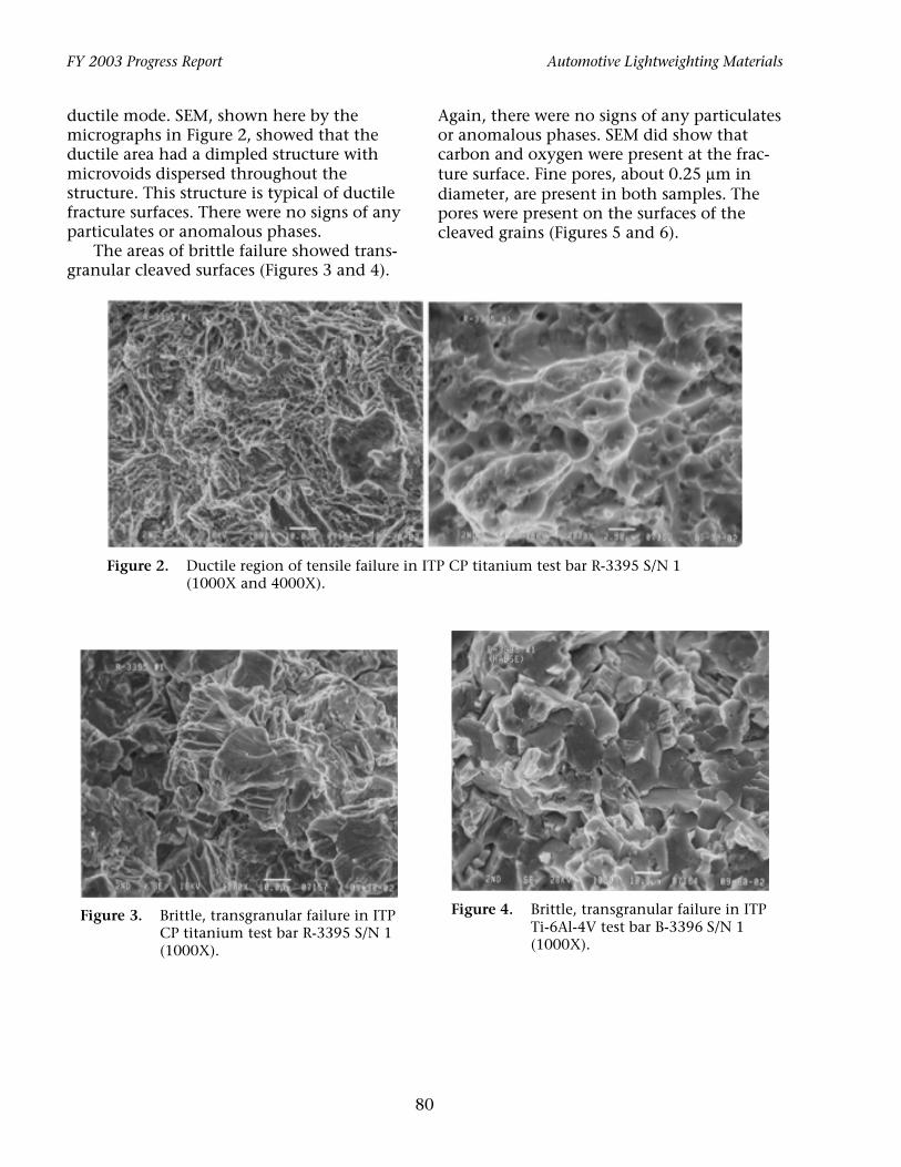
ductile mode. SEM, shown here by the micrographs in Figure 2, showed that the ductile area had a dimpled structure with microvoids dispersed throughout the structure. This structure is typical of ductile fracture surfaces. There were no signs of any particulates or anomalous phases.
The areas of brittle failure showed trans-granular cleaved surfaces (Figures 3 and 4).
Automotive Lightweighting Materials
Again, there were no signs of any particulates or anomalous phases. SEM did show that carbon and oxygen were present at the fracture surface. Fine pores, about 0.25 µm in diameter, are present in both samples. The pores were present on the surfaces of the cleaved grains (Figures 5 and 6).
Figure 2. Ductile region of tensile failure in ITP CP titanium test bar R-3395 S/N 1 (1000X and 4000X).
Figure 3. Brittle, transgranular failure in ITP Figure 4. Brittle, transgranular failure in ITP
CP titanium test bar R-3395 S/N 1 Ti-6Al-4V test bar B-3396 S/N 1
(1000X). (1000X).
80

Automotive Lightweighting Materials FY 2003 Progress Report
Figure 5. Cleaved grains in ITP CP titanium show very fine pores (4000X and 7500X).
Figure 6. The fine pores were also found in cleaved grains in the ITP Ti-6Al-4V alloy (4000X).
.JDSPDIFNJDBM�"OBMZTJT�GPS�-PDBUJPO�PG�
4PEJVN�PS�0UIFS�$BVTFT�PG�&NCSJUUMFNFOU�
A tested tensile specimen made from ITP produced powder was evaluated using metallographic techniques, analytical electron microscopy, and surface spectroscopy techniques in order to provide an explanation for degraded tensile properties in comparison with powders from other sources. Electron microscopy demonstrated that the microstructure included a low dislocation density and a moderate density of nonuniformly distributed pores often containing sodium. AES analysis of a fracture surface produced in situ in the spectrometer vacuum system showed a uniform distribution of
sodium on all surfaces, including microvoid coalescence and brittle surfaces. Electron beam microprobe analysis of ITP powders showed the presence of sodium as small particles on the surface of the titanium powders.
An optical micrograph of the as-electro-polished TEM sample is shown in Figure 7. It reveals the presence of porosity on a fine scale. Pores as large as 1 to 2 µm can be identified.
SEM imaging gave clearer examples of the larger pores in the TEM sample. A series of images with increasing magnification is provided in Figure 8, showing (a) the TEM disk with a large perforation on the left; (b) at intermediate magnification showing the microstructure; and (c) examples of the pores. Note that some pores can be non-spherical and that an unusual halo of small pores was found. An estimate of the pore volume fraction was obtained later from Figure 12 at 0.46%.
The microstructure was also examined in TEM. Examination showed a moderate dislocation density, presumed to be a result of tensile testing, and a fine distribution of nonuniformly distributed pores. Examples at lower magnification are provided in Figure 8 and at higher magnification in Figure 9. Regions in Figure 9 show dislocation structure in the form of loose parallel lines in some grains. Several examples of subgrain structure can also be found that form non-equilibrium grain boundary junctions with
81

FY 2003 Progress Report Automotive Lightweighting Materials
Figure 7. Optical metallography images of an electropolished surface of R-3395 at increasing magnification from left to right.
Figure 8. SEM images of the as-polished TEM disk at increasing magnification from left to right.
Figure 9. TEM showing microstructure and pores in compacted CP titanium made with ITP powder.
82

Automotive Lightweighting Materials FY 2003 Progress Report
angles at 90º and 180º. Figure 10 indicates Smaller pores are on the order of 10 nm in that pore distributions can be nonuniform, diameter. and pore sizes can be quite small. Analytical microscopy demonstrated that Figure 10(b) is imaged in an underfocused several of the pores contained sodium, but condition so that the pores appear dark, no composition segregation at grain boundawhereas the reverse applies to Figure 10(a). ries could be found. An example of composi
tion profiles is provided in Figure 11 with a
(a) (b)
Figure 10. Pore distributions at higher magnification using underfocus on the right (b) to illustrate the voids.
Figure 11. Composition profiles in the vicinity of a pore and a grain boundary.
83

FY 2003 Progress Report
pore containing sodium in Figure 11 (left) and a grain boundary traverse in Figure 11 (right). The image in the center defines the locations for the composition data points. The composition profile for the pore shows a shift in peak response for sodium and oxygen. This is expected to be due to the sensitivity of oxygen measurements with surface undulations. No significant compositional variation can be identified across the grain boundary. Many similar results were obtained for other boundaries, including several intended to sample grain boundary triple points. Boundary profiles showed only occasional enhancement of sodium, generally associated with a nearby pore. Therefore, the porosity contains sodium.
An in situ fracture of sample R3432 was produced using a notched cylindrical sample fractured at –197°C. The fracture was completed within the ultrahigh vacuum chamber of a PHI 680 AES with the goal of determining whether any microchemistry on the fracture surface could be traced back to the low-ductility fracture surfaces. Examples would be the presence of a mixed oxide of Na, Ti, and O, or Na segregation on interfaces. The results of sodium and oxygen were roughly equal on all fracture features, including brittle cleavage surfaces, microvoid coalescence, and other shear-type features. It was concluded that the fracture exposes the sodium-filled pores and that surface diffusion
Automotive Lightweighting Materials
results in a uniform coverage before the first spectra could be taken, which is about 1 h. Examples of the fracture surfaces and AES analysis are given below in Figures 12 and 13.
Figure 12. AES analysis of brittle, cleavage surface of CP titanium made with ITP powder: oxygen: 6.7% and sodium: 17.3% in marked area.
3FGFSFODFT�
1. S. Abkowitz, S. M. Abkowitz, H. Fisher and P. Schwartz, Final Report of Contract No. 409117AU7, Low-Cost Titanium Evaluation, Dynamet Technology, Inc., November 29, 2002.
2. D. S. Gelles and R. H. Jones, Report on Evaluation of Low Cost Titanium Powders; Microstructural Analysis, February 6, 2003.
Figure 13. AES analysis of CP titanium sample made with ITP powder: oxygen concentration 7.6 to 9.1% at locations (a) 1, 2 in. and (b) 1–6 in. sodium concentration ranged from 21 to 27% at the same locations.
84

Automotive Lightweighting Materials FY 2003 Progress Report
'���4USVDUVSBM�3FMJBCJMJUZ�PG�-JHIUXFJHIU�(MB[JOH�"MUFSOBUJWFT�
Principal Investigator: Moe Khaleel Pacific Northwest National Laboratory P.O. Box 999/K9-95, Richland, WA 99352 (509) 375-2438; fax: (509) 375-6605; e-mail: [email protected]
PPG Project Manager: Rick Rueter PPG Industries, Inc., Glass Technology Center P.O. Box 11472, Pittsburgh, PA 15238 (412) 820-8731; fax: (412) 820-8705; e-mail: [email protected]
Visteon Project Manager: Mike Brennan Visteon Glass, 17333 Federal Drive, Suite 230, Allen Park, MI 48101 (313) 755-1879; fax: (313) 755-7485; e-mail: [email protected]
Technology Area Development Manager: Joseph A. Carpenter (202) 586-1022; fax: (202) 586-1600; e-mail: [email protected] Field Technical Manager: Philip S. Sklad (865) 574-5069; fax: (865) 576-4963; e-mail: [email protected]
Contractor: Pacific Northwest National Laboratory Contract No.: DE-AC06-76RL01830
0CKFDUJWFT�
• Optimize glazing systems for cars of the future by decreasing sound transmission while maintaining structural rigidity.
Reduce sound transmitted through sidelights by 6 db by determining the effect of sidelight shape on sound transmittance, investigating sound-dampening materials for operating sidelight glazing, and quantifying the influence of alternate materials (e.g., laminated glass, bilayer glass) on sound attenuation.
Maintain the level of structural integrity while reducing glass thickness by validating the structural rigidity model for various types of urethane used in fixed glazing systems and by expanding/combining existing models to test various alternative constructions and glazing systems for side, rear, and roof windows.
• Reduce vehicle weight through alternate or thinner vision panels and/or by reducing the heat load transmitted through the glass. The goal is to improve the fuel economy of a car by requiring 30% less glass weight.
• Reduce side, rear, and potential roof window glass weight while maintaining acoustics and minimizing price increases.
Consider several material options, including laminated glass, cast-in-place pseudo-laminated glass, and bilayer materials.
Enhance fuel economy from reduced solar energy transmission.
Reduce solar energy transmission through glass by using absorbing substrates and reflective coatings.
85

FY 2003 Progress Report Automotive Lightweighting Materials
Quantify gas mileage improvement opportunities from improvement in solar energy transmission.
"DDPNQMJTINFOUT�
• Fabricated new lightweight windshield and side-body glasses that are 30% lighter than conventional glazing systems.
• Fabricated new glass with polyvinyl butyral (PVB) thickness ranging from 0.5 to 0.76 mm.
• Developed experimental plan for modeling predictions, equipment, and experimental measurements of sound transmission losses in newly used interlayer materials.
• Determined the contributions of the newly used polymeric interlayer materials reduction in infrared (IR) transmittance.
• Designed and fabricated new tooling for ultraviolet (UV) curing of interlayer laminating resin.
• Designed tooling for laminating complex-shaped automotive side windows using newly developed injection technique.
'VUVSF�%JSFDUJPO�
• Develop lightweight side-door glass.
• Investigate the strength and thickness of new polymeric interlayer materials on overall windshield/side-door strength and performance.
• Investigate the overall thermal behavior based on the new interlayer materials, including the effect of the laminated side-door glass.
• Characterize the sound transmission loss of the new lightweight laminated glass.
• Verify and extend the predictive sound transmission loss models to investigate the effect of the new polymeric materials.
• Complete the modeling of the acoustical response of glass.
• Fabricate newly designed tooling for complex automotive side-window shapes and laminate with new interlayer materials.
*OUSPEVDUJPO�
This project is a cooperative research and development agreement (CRADA) between the U.S. Department of Energy, Pacific Northwest National Laboratory (PNNL), Visteon Automotive Systems (Glass Division), and PPG, Inc., which was started in June 2002.
The project will evaluate designs for optimized glazing systems to be used in cars of the future and will work to achieve the goals of FreedomCAR. The primary objective of the project is to reduce vehicle weight, improve fuel economy, and reduce vehicle
emissions. However, to achieve these goals, it is necessary to consider the needs for high levels of structural reliability, competitive manufacturing costs, and passenger comfort from the standpoints of minimal acoustical noise levels and controlled interior temperatures. Energy savings will come from reducing weight by using thinner glazing. Prior studies at PNNL have shown a potential for 30% reductions in weight from thinner glazing. Energy savings will also come from reducing interior heat loads that, in turn, will reduce the demand for air conditioning. The evaluation of alternative glazing concepts will also seek means to improve
86

Automotive Lightweighting Materials
acoustical characteristics that will minimize interior noise levels while maintaining glazing at minimal thickness and weight levels.
-JHIUXFJHIU�8JOEPX�.BOVGBDUVSJOH��
New lightweight window samples were fabricated using 1.6-mm and 2.3-mm glass plies (a conventional automotive glass ply has a thickness of between 2.4 and 2.6 mm; total windshield thickness is usually over 5.2 mm). The new lightweight samples were formed and laminated at PNNL using several different polymer interlayers for comparison.
New lightweight laminated side glass was fabricated using 1.6-mm and 2.3-mm plies. These new window glass samples were constructed: • 1.6-mm glass, 1.8-mm polymer interlayer,
and 1.6-mm glass • 2.3-mm glass, 0.60-mm polymer inter-
layer, and 2.3-mm glass (see Figure 1).
During the fourth quarter of FY 2002, researchers completed the initial conceptual design for injection molding of cast-in-place pseudo-laminates. Initial feasibility studies conducted showed a wide range of flexibility with a variety of polymeric resin systems and viscosities that could be used for laminating the two glass plates. A database on PVB alternatives for the injection molding process was established by collecting information on clear polymer systems that could be used as potential interlayer materials. The database is based on commercially available materials.
Figure 1. Typical window laminate construction.
FY 2003 Progress Report
The evaluations of properties and cost were also addressed. Three of the commercially available materials were altered for specific characteristics in curing and hardness. A table listing specific critical properties was created, and the properties were ranked by relative importance such as impact, tear resistance, and optical transmission. The database of materials was then compared with PVB as the baseline material. Because the optical requirements for the sidelights are not as stringent as those for the windshield, other materials may prove to be more attractive and cost-effective. Other properties are also less aggressive in the ANSI Standard for automotive sidelights, so the comparisons of PVB in properties are conservative. The weighted comparison approach will help determine the direction in which alternative PVB side lamination needs to focus relative to the critical properties.
.BUFSJBM�4FMFDUJPO�GPS�17#�"MUFSOBUJWFT�
The material selection matrix evaluated six different classes of materials against the baseline PVB. The house of quality evaluation matrix compared 15 different criteria in 6 different categories. Table 1 shows how the matrix compares the materials against each other with each critical property and its ranking. The materials are then multiplied times the ranking and then compared against the total.
There were 13 materials evaluated, and 8 were selected to be placed into the House of Quality matrix. The materials selected were broken down into six polymeric systems, such as polyurethanes, acrylics, epoxies, silicones, polyesters, and phthalates.
.BUFSJBM�%PXO�4FMFDUJPO�
The material down-selection was based on the matrix totals and intuition. Sound transmission loss is an important criteria, but it is difficult to find data on commercially available materials. Stress relaxation data are currently being collected on the down-selected material for use in the acoustic
87
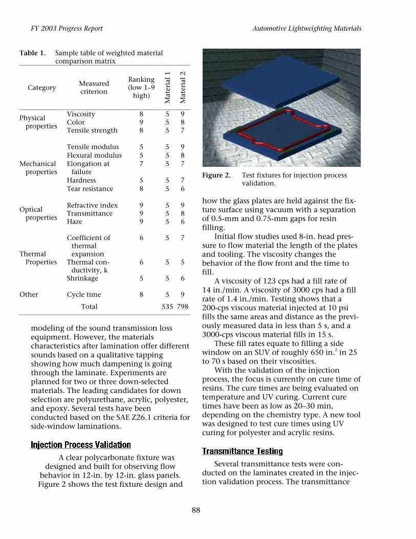
FY 2003 Progress Report Automotive Lightweighting Materials
Table 1. Sample table of weighted material comparison matrix
Ranking Measured
Category (low 1–9 criterion high)
9 8 7
9 8 7
7 6
9 8 6
7
5
6
9
Mat
eria
l 1
Mat
eria
l 2
Viscosity 8 Color 9 Tensile strength 8
Tensile modulus 5 Flexural modulus 5
5 5 5
5 5 5
5 5
5 5 5
5
5
5
5
Physical properties
Mechanical properties
Optical properties
Thermal Properties
Other
Elongation at failure
Hardness Tear resistance
Refractive index TransmittanceHaze
Coefficient of thermal expansion
Thermal conductivity, k
Shrinkage
Cycle time
Total
7
5 8
9 9 9
6
6
5
8
Figure 2. Test fixtures for injection process validation.
how the glass plates are held against the fixture surface using vacuum with a separation of 0.5-mm and 0.75-mm gaps for resin filling.
Initial flow studies used 8-in. head pressure to flow material the length of the plates and tooling. The viscosity changes the behavior of the flow front and the time to fill.
A viscosity of 123 cps had a fill rate of 14 in./min. A viscosity of 3000 cps had a fill rate of 1.4 in./min. Testing shows that a 200-cps viscous material injected at 10 psi fills the same areas and distance as the previously measured data in less than 5 s, and a 3000-cps viscous material fills in 15 s.
These fill rates equate to filling a side window on an SUV of roughly 650 in.2 in 25 to 70 s based on their viscosities.
With the validation of the injection process, the focus is currently on cure time of resins. The cure times are being evaluated on temperature and UV curing. Current cure times have been as low as 20–30 min, depending on the chemistry type. A new tool was designed to test cure times using UV curing for polyester and acrylic resins.
5SBOTNJUUBODF�5FTUJOH�
Several transmittance tests were conducted on the laminates created in the injection validation process. The transmittance
535 798
modeling of the sound transmission loss equipment. However, the materials characteristics after lamination offer different sounds based on a qualitative tapping showing how much dampening is going through the laminate. Experiments are planned for two or three down-selected materials. The leading candidates for down selection are polyurethane, acrylic, polyester, and epoxy. Several tests have been conducted based on the SAE Z26.1 criteria for side-window laminations.
*OKFDUJPO�1SPDFTT�7BMJEBUJPO�
A clear polycarbonate fixture was designed and built for observing flow
behavior in 12-in. by 12-in. glass panels. Figure 2 shows the test fixture design and
88
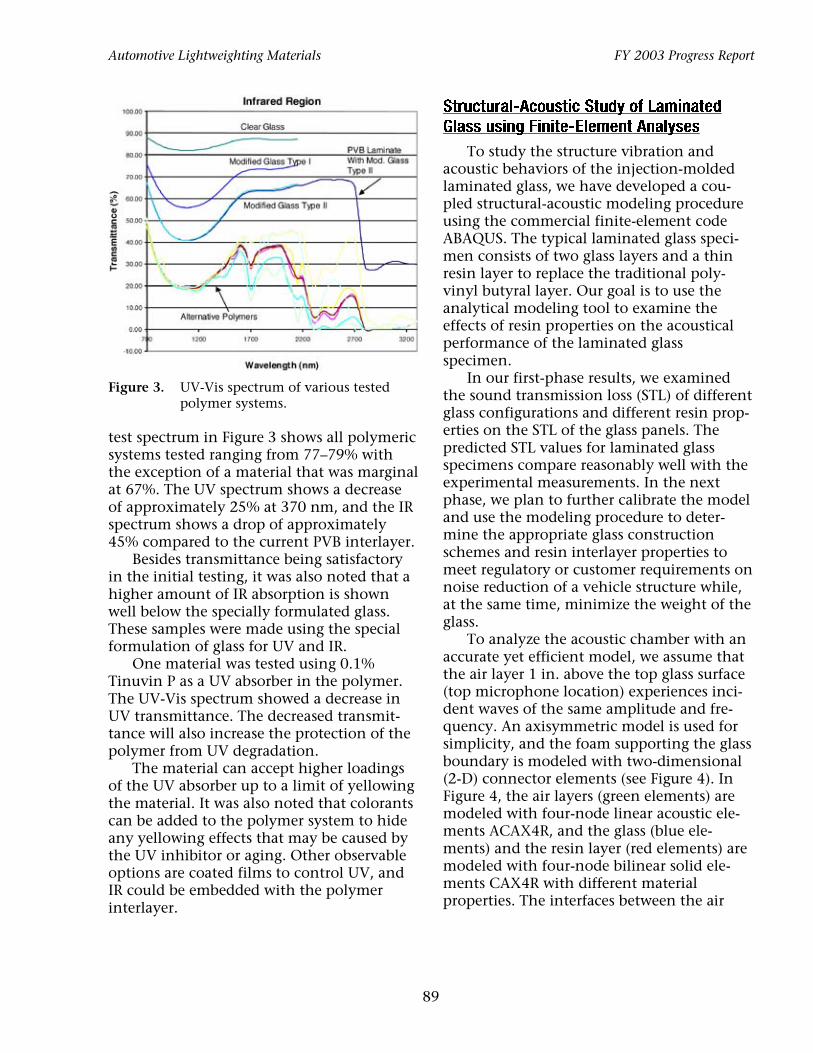
Automotive Lightweighting Materials FY 2003 Progress Report
Figure 3. UV-Vis spectrum of various tested polymer systems.
test spectrum in Figure 3 shows all polymeric systems tested ranging from 77–79% with the exception of a material that was marginal at 67%. The UV spectrum shows a decrease of approximately 25% at 370 nm, and the IR spectrum shows a drop of approximately 45% compared to the current PVB interlayer.
Besides transmittance being satisfactory in the initial testing, it was also noted that a higher amount of IR absorption is shown well below the specially formulated glass. These samples were made using the special formulation of glass for UV and IR.
One material was tested using 0.1% Tinuvin P as a UV absorber in the polymer. The UV-Vis spectrum showed a decrease in UV transmittance. The decreased transmittance will also increase the protection of the polymer from UV degradation.
The material can accept higher loadings of the UV absorber up to a limit of yellowing the material. It was also noted that colorants can be added to the polymer system to hide any yellowing effects that may be caused by the UV inhibitor or aging. Other observable options are coated films to control UV, and IR could be embedded with the polymer interlayer.
4USVDUVSBM�"DPVTUJD�4UVEZ�PG�-BNJOBUFE�
(MBTT�VTJOH�'JOJUF�&MFNFOU�"OBMZTFT�
To study the structure vibration and acoustic behaviors of the injection-molded laminated glass, we have developed a coupled structural-acoustic modeling procedure using the commercial finite-element code ABAQUS. The typical laminated glass specimen consists of two glass layers and a thin resin layer to replace the traditional polyvinyl butyral layer. Our goal is to use the analytical modeling tool to examine the effects of resin properties on the acoustical performance of the laminated glass specimen.
In our first-phase results, we examined the sound transmission loss (STL) of different glass configurations and different resin properties on the STL of the glass panels. The predicted STL values for laminated glass specimens compare reasonably well with the experimental measurements. In the next phase, we plan to further calibrate the model and use the modeling procedure to determine the appropriate glass construction schemes and resin interlayer properties to meet regulatory or customer requirements on noise reduction of a vehicle structure while, at the same time, minimize the weight of the glass.
To analyze the acoustic chamber with an accurate yet efficient model, we assume that the air layer 1 in. above the top glass surface (top microphone location) experiences incident waves of the same amplitude and frequency. An axisymmetric model is used for simplicity, and the foam supporting the glass boundary is modeled with two-dimensional (2-D) connector elements (see Figure 4). In Figure 4, the air layers (green elements) are modeled with four-node linear acoustic elements ACAX4R, and the glass (blue elements) and the resin layer (red elements) are modeled with four-node bilinear solid elements CAX4R with different material properties. The interfaces between the air
89

FY 2003 Progress Report Automotive Lightweighting Materials
Figure 4. Coupled structural-acoustic finite-element model.
(acoustic elements) and glass (solid elements) are constrained at their abutting surfaces using the *TIE option. The thicknesses of both glass layers are set to be 2.3 mm, and the intermediate resin layer is 0.5 mm thick.
The incident wave comes from the top of the air layer with specified frequency and amplitude. The pressure response of the air at point A, 1-in. below the glass center, is monitored as output of the analyses. Both transient explicit dynamic analysis and steady state dynamics procedures are used, and the pressure results consist of both transient pressure responses and frequency sweep pressure response.
Figures 5(a) and (b) show the input pressure wave form at the top of the air layer and the output pressure wave form at point A for input frequency of 1000 Hz. As the transient response dies out, the dynamic pressure response at point A has the same frequency as the incident pressure wave frequency.
Steady state dynamic analyses are then performed to calculate the structure response for incident waves of 400 Hz to 8000 Hz. The structural response in terms of pressure amplitude vs incident frequency is then achieved. The values of sound transmission loss (STL) can then be determined using the following equation:
dB STL ) = log( 20 p1 ) , (1)(
pinput
Figure 5. (a) Input acoustic wave form of 1000 Hz and (b) predicted acoustic wave form: transient behavior.
pwhere p1 is the response wave amplitude, and
input is the input wave amplitude. Figure 6 shows the predicted STL values for the frequency sweep compared with discrete STL measurement from our experiments. Because
Figure 6. Predicted STL results compared with experimental results.
90

Automotive Lightweighting Materials
the system has a natural frequency around 3500 Hz, we observe a dip in STL around 3440 Hz. This is consistent with the experimental findings. The predicted STL values compare reasonably well with the acoustic chamber measurements at frequencies higher than 2000 Hz. For frequencies lower than 2000 Hz, the prediction is higher than measurement.
The next step of our work will be to establish the more realistic boundary conditions to model the acoustic chamber and to obtain better correlation for low-frequency responses between prediction and experiments.
"DPVTUJD�$IBNCFS�5FTU�4FUVQ�
An acoustic chamber was designed and fabricated for testing 12-in. by 12-in. test panels. Figure 7 shows the newly built test chamber. The acoustic chamber is capable of covering the noise spectrum associated with automotive noises.
Figure 7. Acoustic test chamber for glass laminations.
FY 2003 Progress Report
The focus frequencies were from 1 kHz to 8 kHz. Comparative testing was initially done showing the difference between each one of the candidate interlayer materials. Figure 8 shows preliminary results of different candidate test materials. The STL was 3–7 db better than the PVB interlayer at different frequency ranges. A model of how modifying the interlayer material could further improve the acoustic properties of the side windows is ongoing.
Figure 8. STL comparison of different polymer interlayers.
3JOH�PO�SJOH�5FTUJOH�
Comparative ring-on-ring testing was also performed on candidate interlayer materials. Figure 9 illustrates that all materials performed satisfactorily. Qualitatively, all materials bonded well to the glass. During glass fracture, none of the glass material was released from the interlayer. The sample size is too small for a statistical comparison of the PVB properties, but future work will look at different ball-and-dart impact testing.
Figure 9. Ring-on-ring data.
91

FY 2003 Progress Report Automotive Lightweighting Materials
0UIFS�5FTUJOH�
PPG is currently testing one set of glass panels that will provide data on how well they hold up to rigorous testing by a leading window supplier. Preliminary testing done was boil testing for 6 h with good results on all candidate materials. Hot and cold testing was done with no delaminations, which PPG will also investigate further.
'VUVSF�8PSL�
Future work will focus on fabrication of larger automotive side windows and further testing by the glass manufacturer. New tooling for a 650-in.2 side window is designed,
and materials are in the procurement process. Further, 12-in. by 12-in. testing plates will continue to be made with other interlayer materials and given to PPG for further testing. Other testing will focus on effects of the door slam on the larger windows. The overall mechanical, thermal, and acoustical behavior of the new lightweight glass will be evaluated using both experimental and analytical procedures. Modeling efforts will continue to focus on stone-impact studies and acoustics. Work will also be conducted to enhance and extend the numerical tool for design of lightweight glass to include stresses encountered during the glass fabrication process.
92