lecture 12: laboratory and industrial...
TRANSCRIPT

"An ounce of careful plant design is worth ten pounds of reconstruction."
LECTURE 12: LABORATORY AND INDUSTRIAL CATALYTIC
REACTORS: SELECTION, APPLICATIONS, AND DATA ANALYSIS
I. Introduction A. Why study reactors?
B. Definition and classification of reactors
C. Reactor/process design perspective: from the laboratory to the full-scale plant
D. Selection of reactors in the laboratory and plant
II. Laboratory and Bench Scale Reactors A. Kinds
B. Criteria for selection of lab/bench scale reactors; applications
III. Plant Reactors A. Common types
B. Fixed catalyst bed reactors: characteristics, advantages, limitations
C. Fluidized beds: characteristics, advantages, limitations
D. Criteria for selection
IV. Collecting, Analyzing and Reporting Data from Laboratory Reactors A. General approach and guidelines
B. Criteria for choosing catalyst form and pretreatment, reaction conditions
C. Choosing mode of reactor operation; differential and integral reactors
D. Analyzing and reporting data from laboratory reactors
1. Analysis of rate data: objectives and approach
2. Integral analysis
3. Differential analysis
V. Examples

New HDS Unit, ARCO Carson, CA Refinery


I. Introduction
A. Why study reactors?
1. The design of catalyst and reactor
are closely interrelated.
2. Design of catalytic processes
requires a knowledge reactor
design, operation optimization and
selection
3. Progress in improving our standard
of living depends on our ability to
design reactors
4. Our personal existence depends on
controlling cellular reactions in our
body while that of the human race
hangs on the outcome of enormous
global reactions.

B. Definition and Classification of Reactors
1.What is a Reactor?
a. A device that encloses the reaction space, and which houses the
catalyst and reacting media.
b. A container to which reactants are fed and products removed, that
provides for the control of reaction conditions.
2. Classification of Reactors
a. Size
b. Methods of charging/discharging: batch or steady-state flow
c. Motion of particles with respect to each other
d. Fluid flow type: tubular or mixed-fluid

Table 12.1 Classification of Catalytic Reactors
Basis for Classification Classes Examples
Size Laboratory Bench scale
Pilot scale
Plant scale
0.5 cm diam. tubular microreactor (0.1-1 g catalyst) 2.5 cm diam. x 30-50 cm long tubular reactor (50-200 g catalyst)
7.5 cm diam x 6-10 m long tubular reactor (20-100 kg catalyst)
1-6 m diam x 20-50 m long tubular reactor (20-100 metric tons cat.)
Methods of charging and discharging
Batch Flow, steady state
Stirred liquid and solids a. tubular, fixed catalyst bed
b. slurry, mixed fluid, mixed solids
Motion of catalyst particles relative to each
other
Fixed Relative motion
Tubular fixed solids (fixed bed) a. fluidized bed
b. slurry bubble column
Fluid flow Tubular, plug flow Mixed fluid flow
Turbulent gas in tubular fixed bed Slurry reactor with mechanical stirring

C. Reactor/process
design perspective
Hardware and Software
Scientific & Engineering Tasks
Scientific & Engineering Disciplines
Discover Reaction
Laboratory Reactor
Kinetic Model Development
Chemical Kinetics and Catalysis
Rate/Selectivity & Rate Equation
Reactor Model
Reactor Model Development
Reaction Engineering & Mathematics
Reactor /Process Design
Catalytic Reactor Design
Pilot Plant Reactor
Finl. Plant Design & Economic Studies
Large Scale Plant
Process Design Economics
Intrinsic
Kinetics
Catalyst Prop.
Diff., Mass Trans
Fig. 12.1 Structure of Catalytic Process
Development [adapted from J. M. Smith,
Chem. Eng. Prog., 64, 78 (1968)].

D. Choosing reactors in the lab and plant
Reactors are used for many different purposes:
1. to study the mechanisms and kinetics of chemical reactions to provide data for validation of process simulations
2. to investigate process performance over a range of process variables
3. to obtain design data
4. to produce energy, materials and products.
Choosing the right reactor is critical to the engineering
process and is dictated by many different variables such as
• reaction type
• rate of deactivation
• economics
• other process requirements

II. Common Lab and Bench Scale Reactors
1. fixed bed tubular
2. stirred gas, fixed bed
3. stirred liquid/gas, stirred catalyst
4. fluid bed
5. fixed bed, transient gas flow
Laboratory and bench-scale reactors vary greatly in size,
complexity, cost, and application.

Table 12.2 Laboratory and Bench-Scale Catalytic Reactors Classes Class Examples Features
Fixed bed tubular Laboratory differential/integral
Bench-scale integral
0.5 cm diam tubular microreactor (0.1-1 g catalyst, solid catalyst, gas fluid; glass or metal
2.5 cm diam. x 30-50 cm long tubular reactor (50-200 g
catalyst); solid catalyst, gas or liquid fluid; metal
Stirred gas, fixed bed Stirred batch Batch recycle
Berty
Carberry
microreactor, 1 g catalyst, glass or met. microreactor, 1 g catalyst, glass or met.
bench-scale, 2-200 g cat., 10-100 atm, stainless steel,
circulating gas
bench-scale, 2-200 g cat., 10-100 atm, stainless steel,
spinning catalyst basket
Stirred liquid/gas, stirred catalyst
Stirred batch Bubble slurry
bench-scale, 2-50 g cat., 1-200 atm, glass or metal heterogeneous or homogeneous catalyst
Fluid bed
Laboratory Bench-scale transport
Recirculating transport
microreactor, 1-5 g cat, 1 atm, glass bench-scale, 50-200 g catal, 1-10 atm, metal
Fixed bed, transient gas flow
Pulse flow TPD/TPSR
Radio tracer exchange
MS/Transient response
Frequency response
microreactor, 0.1-1 g catalyst, glass or metal, 1 atm

Fig. 12.2 Features of representative laboratory
reactors [Levenspiel, 1979].

10/30 female joint
10/30 male joint
9 mm O-ring joint
4 ft. preheater coil of2 mm capillary tubing
Thermocouple guide of2mm capillary tubing
7"
Fritted disc
Catalyst space
Figure 12.3 Laboratory Pyrex FBR reactor (courtesy of the BYU
Catalysis Laboratory).

Figure 12.4 Berty internal recycle reactor.

Gas-Liquid CSTR (UCSB) Batch Reactor (UCSB)

Bench scale reactor (courtesy of Shell Corp.)

II. Laboratory and Bench Scale Reactors
B. Criteria for selection of lab and bench-scale reactors; applications
1. Satisfying intended application
2. Avoiding deactivation
3. Avoiding inter- and intra- particle heat and mass transport limitations
4. Minimizing temperature and concentration gradients
5. Maintaining ideal flow patterns
6. Maximizing the accuracy of concentration and temperature
measurements
7. Minimizing construction and operating costs

Table 12.3 Seven Criteria for Selection of Laboratory and Bench-Scale
Catalytic Reactors
Criterion Issues Involved/Measures of/Methods to Meet Criterion
1. Satisfy purpose of measurement (i.e., application)
Measure: (1) intrinsic activity/selectivity, (2) kinetics of reaction and deactivation
Obtain mechanistic understanding
Simulate process
2. Avoid catalyst deactivation where possible; where not, decide if fast or
slow
See Chap. 5 (B&F) on avoiding different kinds of catalyst deactivation Fast decay causes activity and selectivity disguises and requires use of
transient or transport reactor
Slow decay best studied using CSTR or differential reactor
3. Avoid inter- and intra-particle heat and mass transport limitations
Thiele modulus less than 0.5; small particles or thin catalyst layer Minimize film thickness with high flow rates, turbulence
Operate at low conversions
Use CSTR or differential reactor
4. Minimize temperature and concentration gradients
Gradients cause activity and selectivity disguises Maximize mixing in batch reactor and CSTR; use inerts
Use CSTR or differential reactor where possible
5. Maintain ideal flow patterns Minimize mixing and laminar flow in tubular reactors; Maximize mixing and minimize gradients in CSTR
Avoid gas or liquid holdup in multi-phase reaction systems
6. Maximize accuracy of concentration and temperature measurements
Sensitive analytical methods and well-placed, sensitive probes Sufficiently high product concentrations
7. Minimize construction and operating costs
Select the least expensive reactor that will satisfy the other criteria Consider ways of minimizing size of catalyst and volume of reactant gas

Table 12.4 Applications of Lab/Bench Test Reactors Reactor Type Catalyst Selection
Activity/Selectivity
Reactor/Design Fundamental
Mechanism
Process
Simulation
Life Kinetics
Integral
Adiabatic X (overall avg. conv.) X X
Isothermal X (overall conv. at T) X X
Differential
Single Pass X (intrinsic) X (intrinsic) X (eliminate)
Recycle X (intrinsic) X (intrinsic) X (eliminate)
Stirred gas X (intrinsic) X (kinetics) X (intrinsic) X (eliminate) X (model)
Fluid bed/ Transport
X (fast deact.) X (fast deact.) X (fast deact.)
X
Micro-pulse X (comparative, initial) X
Transient X (elem. steps)
X X (model)
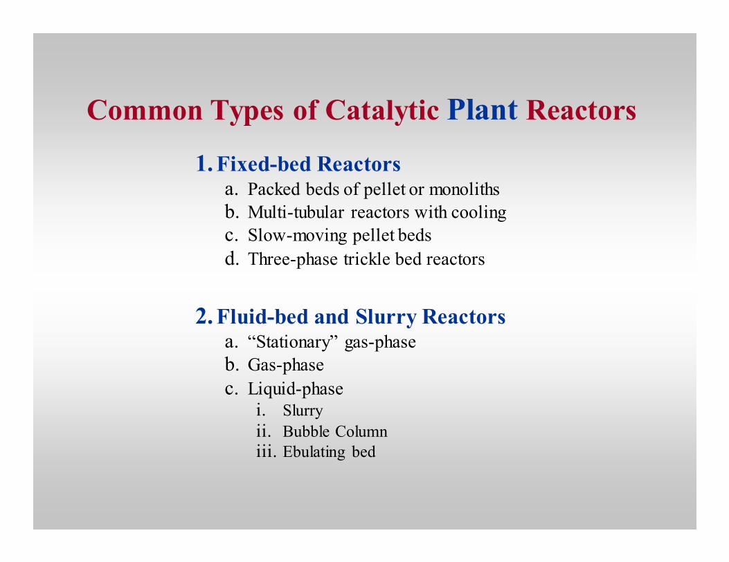
Common Types of Catalytic Plant Reactors
1.Fixed-bed Reactors a. Packed beds of pellet or monoliths
b. Multi-tubular reactors with cooling
c. Slow-moving pellet beds
d. Three-phase trickle bed reactors
2.Fluid-bed and Slurry Reactors a. “Stationary” gas-phase
b. Gas-phase
c. Liquid-phase i. Slurry
ii. Bubble Column
iii. Ebulating bed

Table 12.5 Characteristics of Plant-Scale Fixed Bed Reactors
Advantages
1. Ideal plug (or mixed) flow
2. Simple analysis
3. Low cost, low maintenance
4. Little loss or attrition
5. Greater variation in operating conditions and contact times is possible
6. Usually a high ratio of catalyst to reactants
long residence time complete reaction
7 Little wear on catalyst and equipment
8. Only practical, economical reactor at very high pressures
Disadvantages
1. Poor heat transfer in a large fixed bed.
a. Temp. control and measurement difficult
b. Thermal catalyst degradation
c. Non uniform rates.
2. Non uniform flow patterns e.g. channeling 3. Swelling of the catalyst; deformation of the reactor
4. Regeneration or replacement of the catalyst is
difficult - shut down is required.
5. Plugging, high pressure drop for small beads or
pellets - ∆P is very expensive. 6. Pore diffusional problems intrude in large pellets
Overcoming the Disadvantages
1. Monolithic supports overcome disadvantages 2, 5 & 6
2. Temperature control problems are overcome with:
a. Recycle
b. Internal and external heat exchanges
c. Staged reactors d. Cold shot cooling
e. Multiple tray reactor - fluid redistributed & cooled between stages.
Catalyst is easily removed - varied from tray to tray.
f. Use of diluents
g. Temperature self regulation with competing reactions, one endo and one exothermic. h. Temp control by selectivity and temporarily poisoning the catalyst

B. Fixed-bed reactors: characteristics, advantages,
limitations
Advantages:
• Flexible- large variation in operating conditions and contact times
is possible
• Efficient- long residence time enables a near complete reaction
• Generally low-cost, low-maintenance reactors
Disadvantages:
• Poor heat transfer with attendant poor temperature control
• Difficulty in regenerating or replacing spent catalyst

Product
Feed
Inert balls
Catalyst
Reactants Inlet
Liquid OrGaseous
Bath
ReactorTube
Gas OrLiquidFlow
OutletProduct
ReactorTube
a..
I II III IV
1 2 3 4
Fresh feed
Recycle gas
b.
Fig. 12.6 Commercial fixed-bed reactor designs for controlling
temperature: (a) multi-tubular heat-exchange reactor, (b) series of
fixed-bed, adiabatic reactors with interstage heating or cooling.
Figure 12.5 Commercial
fixed-bed, adiabatic catalytic
reactor.

Advantages
1. Frequent regeneration of the catalyst
possible.
2. Rapid mixing of solids in fluid beds means
uniform gas composition.
3. Isothermal operation and efficient
temperature control is practical.
4. Small-diameter particles in fluid minimize
pore diffusional resistance.
5. Improved thermal efficiency because of
high heat transfer rates.
6. In the case of highly exothermic, liquid
phase reactions, slurry reactors are less
complex and less expensive than heat-
exchange-tubular systems.
Disadvantages
1. Fluidized beds are complicated systems
involving multiple reactors, heat exchangers,
extensive valving and piping to provide
continuous system.
2. $$ Extensive investment. Maintenance is
high.
3. Fluid flow is complex in fluidized and slurry
bubble columns - less than ideal contacting.
Product distribution is changed - less
intermediate formed in a series reaction.
4. Only a small variation in residence time
possible. Low residence times. Conversion
may be limited.
5. Attrition & loss of Catalyst.
Table 12.6
Characteristics of Plant-Scale Fluidized and Slurry Bed Reactors

Deentrainedvapor
Product
Spentcatalyst
Hydro-clone
Freshcatalyst
Feed
a.
Continuousphase
Product
Dispersedphase
b.
Figure 12.7 Liquid-phase slurry reactors: (a) forced-circulation,
slurry-bed reactor, (b) bubble-column, slurry-bed reactor.

H2
reactants + H2
products
shaft heater
liquid
P
productwithdrawal
suspendedcatalystparticles
rotor
pressurevessel
to heat source
H2 from reservoir
(consumption measured)
Figure 12.8 Batch-slurry reactor for hydrogenation
of specialty chemicals.

Product
Steam stripping
Flue gas
Fluid-bedregenerator
Air
Transfer line
Feed
Transfer-line reactor
Fig. 12.9 Design of typical FCC transfer-line (riser)
reactor with fluidized-bed regenerator.

Products
Riserreactor
Catalyststripper
Steam
Reactorfeed
Steam
Air
Overflowwell
Regenerator
Fluegas
Cyclone
a. Products
Cyclone
Reactor
Catalyst stripper
Steam
Air
Reactor
Regenerator
Flue gas
feed
b.
Figure 12.10 Commercial FCC riser reaction designs (a) Exxon, (b) UOP.

Fluid Cat Cracker (Chevron) Stacked Fluid Cat Cracker (UOP)

Shell Cat-Cracker All-riser Cracking FCC Unit

Criteria for Selection of Plant Reactors
1.General Criteria.
a.deactivation rate and regeneration policy
b.reaction conditions
c.catalyst strength and attrition resistance
d.process economics
2.Role of Cp/(-∆∆∆∆Hr)
slope =
T
XA
Cp
-∆HR
1rA
XA
1
100
10
1000
T
XA 1rA
XA
c
d
a
b
Fig. 12.11 (a) Operating line for a
highly exothermic reaction in an ideal
tubular reactor with pure reactant and
(b) corresponding reciprocal rate versus
conversion curve and area V/FAo for a
CSTR. (c) Operating line for a highly
exothermic reaction in an ideal tubular
reactor with dilute reactant and (d)
corresponding reciprocal rate versus
conversion curve and area V/FAo for a
PFR.

3. Optimal Temperature Progression
Figure 12.12 Optimum temperature progression (and locus of
maximum rates) of (a) reversible endothermic reaction and (b)
reversible exothermic reactions.

Exothermic reversible Exothermic irreversible Endothermic
Qin Q
Optimum
Tmax
T T T
Tmax
Coldfeed
Furnace
Adiabaticreactors
Coldproduct
A B C
D E
F G
Q Q Q
XA
a
b
Fig. 12.13 (a) Use of staged adiabatic tubular fixed-bed reactors with interstage cooling to achieve optimum
temperature progression in the cases of exothermic reversible, exothermic irreversible and endothermic
reactions. (b) Design schematic for staged adiabatic fixed-bed reactors with interstage furnace heating for a strongly endothermic reaction such as reforming of methane.

Collecting, Analyzing and Reporting Data
from Laboratory Reactors
Different purposes:
1. activity/selectivity and life data for catalyst selection
2. chemical reaction mechanistic and kinetic data for understanding the
reaction at a fundamental level, modeling the reaction process, and/or
designing reactors
3. process variable data over a wide range of conditions for purposes of
designing large-scale reactors, experimentally validating models and
optimizing the catalytic process.
Data collection typically involves three major steps (Fig. 12.14):
1. selection of a reaction and catalyst
2. selection of a reactor type
3. analysis of the data

SelectReaction
andCatalyst
Criteria Data
Select reactorand conditions Data Analysis
IntegralDifferentialInitial Rates
BatchFlow CSTR Plug - integral or differential
mechanismrate expressionprocess optimization
new experiments
Figure 12.14 Process of obtaining rate and kinetic data; note that
statistical methods are used in Steps 2 and 3 and in the recycle process.

Table 12.7 Proposed Guidelines for Choosing Catalyst Form, Pretreatment, and Reaction Conditions and for Reporting of Data [Ribiero et al., 1996].
1. Catalyst Properties and Characterization
a. Catalysts/surfaces should be carefully prepared and pretreated so as to be free of solid contaminants such as sulfur, chlorides, and carbon that might affect activity.
b. Support effects should be avoided by studying reactions on single crystals of the active catalytic phase, e.g., metal, metal films, and/or relatively highly-concentrated, poorly-dispersed supported metals. Preparation methods should be used which minimize decoration of the metal surface, e.g., decomposition of metal carbonyls on supports. Supported base metal catalysts need to be well-reduced to avoid complications due to unreduced metal oxides.
c. In the case of structure-sensitive reactions, effects of surface structure and/or dispersion need to be taken into account.
d. Metal dispersion/surface area should be measured using proven and/or standard (ASTM) methods, e.g., hydrogen chemisorption or titration rather than CO chemisorption for metals.
e. Methods of preparation and characterization should be reported in detail. Methods for calculating surface area and dispersion should also be carefully reported. Reporting these methods and the surface area or dispersion of catalyst samples should be a requirement for publication of specific activity data.

Table 12.7 Continued
2. Reaction Conditions
a. TOF and kinetic data must be measured in the absence of pore diffusional restrictions, film mass transfer limitations, and heat transfer limitations (generally at low temperature and low conversion). Experimental evidence and calculations based on well-known criteria (e.g., the Thiele modulus for pore diffusional resistance) should be provided in publications to demonstrate that the data were obtained in the absence of these effects.
b. TOF and kinetic data must be measured in the absence of deactivation effects, e.g., poisoning, coking, and sintering. The burden of proof that such effects are absent should be on the authors of a publication.
c. TOF data should be collected over wide ranges of temperature and reactant concentrations to facilitate valid comparison with data from other laboratories and to provide meaningful data for determining temperature and concentration dependencies.
d. TOF data should be reported at specified conditions of temperature, reactant concentrations, and conversion. These specifications should be used by reviewers and editors as a minimum reporting requirement for publication in a journal.

Analyzing and reporting data from laboratory
reactors
1. Analysis of rate data: objectives
a. finding a rate equation
b. determining catalyst activity, selectivity and activity stability
c. determining the effects of important process variables such as
temperature, pressure, reactant concentrations, and space velocity
on activity, selectivity and stability
2. Extracting rate constants and concentration dependencies
a. Integral analysis
b. Differential analysis

WF
dx(-rA)
x
x
xx
x
x
o
Figure 12.15
Test for integral analysis of rate data involving plot of
W/FAo versus integrated reciprocal rate.
Integral analysis of rate data involves the following steps:
1. A series of runs are made in a packed bed at a fixed initial concentration CAo and a fixed temperature
while varying the catalyst mass W and/or the initial molar flow rate FAo to generate a range of W/FAo
values at different conversions (XA).
2. A candidate rate equation is selected for testing using the design equation for plug flow. First try simpler rate equations, e.g. zero-, first- and second-order irreversible and use differential analysis to scope out possible reaction orders.
3. The left-hand side (W/FAo) and right-hand side (the integral of 1/−rA) of the design equation are each evaluated numerically and plotted against each other, as shown in Figure 4.19 to test for linearity.
4. Linearity of the plot (e.g. Figure 12.15) is used as the criterion for judging if the candidate rate equation is a useful model of the data, i.e. consistent with the data.
5. This should be followed by a nonlinear regression with statistical analysis to determine kinetic parameters.
Integral Analysis of Rate Data

Differential Analysis of Rate Data
X
slope = α
ln CA
b
ln (-rA)
W/FA0
XA
1.0
0.5 X
X XXX
XX
X
X
0
slope = -rA'a
XX
X
Fig. 12.16
(a) Differential analysis to obtain
reaction rates. (b) Plot to obtain
reaction orders.
Differential analysis of rate data involves the following steps:
1. The identical series of runs (as in integral analysis) are made in a packed bed at a fixed initial
concentration CAo and fixed temperature while varying the catalyst mass W and/or the initial molar flow rate FAo to generate a range of W/FAo values at different conversions (XA).
2. A plot of conversion XA versus W/FAo data is made for each set of runs at a fixed temperature. A best fit of the data is made using a simple quadratic or cubic equation, and the corresponding curve is plotted on
the same figure, as illustrated in Figure 4.20(a).
3. Tangents to the curve are drawn at regular intervals along the curve corresponding to the best fit, and the
slopes of these tangents are evaluated (Figure 12.16a); the slopes on this plot correspond to the reaction rate, i.e. dXA = (−rA)[d(W/F)]. Tangents can be evaluated more accurately by differentiating the equation
for the best fit of the data and evaluating the derivative at various intervals over the data set.
4. Values of −rA versus XA are plotted on linear or log-log plots to determine reaction orders. For example,
for an irreversible reaction in which data are fitted by a simple power rate law, −rA = k CAα, a plot of
ln(−rA) versus ln(CA) is linear with a slope α (Figure 12.16b).
5. Differential analysis is a useful scoping tool to explore forms of the rate expression; however, in the end a nonlinear regression and rigorous statistical analysis is required to obtain kinetic parameters with
acceptable accuracy.

References
1. O. Levenspiel, Chemical Reaction Engineering, 2nd and 3rd Eds., John
Wiley and Sons, 1972, 1999.
2. O. Levenspiel, The Chemical Reactor Minibook, OSU Bookstores, 1979.
3. J.M. Smith, Chemical Engineering Kinetics, 3rd Ed., McGraw Hill, 1981.
4. "Reactor Technology," Kirk-Othmer: Encyclopedia of Chemical Technology, Vol. 19, 3rd Ed, John Wiley, 1982, pp. 880-914.
5. G.F. Froment and K.B. Bischoff, Chemical Reactor Analysis and Design, John Wiley, 1990.
6. O. Levenspiel, The Chemical Reactor Omnibook, 1993, OSU Bookstores, 1993.
7. C. H. Bartholomew and R. J. Farrauto, Fundamentals of Industrial Catalytic Processes, Chapman and Hall, 2005, Chap. 4.