launch vehicle system requirements and restraints … · 1.3.2 launch vehicle system objectives...
TRANSCRIPT

‘ 1
.
LAUNCH VEHICLE SYSTEM REQUIREMENTS
AND RESTRAINTS F O R
THE NIMBUS C PROJECT
NIM57-D
Approved:
4 2
Nimbus Pro jec t Manager
Approved:
Edward A. Agena Coordinato
https://ntrs.nasa.gov/search.jsp?R=19680002556 2020-05-14T02:25:02+00:00Z
.
I n r e p l y r e f e r t o : 623.6(65)-61
TO : D i s t r i b u t i o n
FROM : Edward A. Rothenberg, Agena Coordinator
SUBJECT: Launch Vehic le System Requirements and R e s t r a i n t s f o r t h e Nimbus-C P r o j e c t
REF. : LeRC l t r 9410 PCW, same s u b j e c t , d a t e d 9 February 1965, H i m m e l t o P r e s s
ENCL. : N I M 57-D, "Launch Vehic le System Requirements and R e s t r a i n t s f o r t h e Nimbus-C P r o j e c t , December 1964, r e v i s e d March 1964
The e n c l o s u r e has been r e v i s e d t o r e f l e c t LeRC comments p r e s e n t e d i n t h e r e f e r e n c e and i s d i s t r i b u t e d i n . accordance w i t h t h e c o n s o l i d a t e d LeRC and GSFC d i s t r i b u t i o n list. Appropr ia te r e v i s i o n n e c e s s i t a t e d by i n t e r f a c e agreements reached d u r i n g t h e Nimbus A p r i l 7-8, 1965 meeting a t LMSC, Sunnyvale w i l l be i n c o r p o r a t e d a t a l a t e r d a t e .
1
Edward A, Rothenberg Agena C o o r d i n a t o r
EAR/JHW/al

MECEDING PAGE BLANK NOT FILMED .
CONTENTS
Page
TITLE PAGE
TABLEOFCONTENTS . . . . . . . . . . . . . . . . . . . . . . . . . . . . iii
ILLUSTRATIONS . . . . . . . . . . . . . . . . . . . . . . . . . . . . . . . . vi
TABLES . . . . . . . . . . . . . . . . . . . . . . . . . . . . . . . . . . . . . . vii
SECTION1 GENERAL . . . . . . . . . . . . . . . . . . . . . . . . . . . . 1-1
1.1 Scope . . . . . . . . . . . . . . . . . . . . . . . . . . . . . . . . . . . . . 1-1
1.3 Mission Objectives . . . . . . . . . . . . . . . . . . . . . . . . . . . . 1-1 1.3.1 Spacecraft Sys tem Objectives . . . . . . . . . . . . . . . . . 1-1 1.3.2 Launch Vehicle System Objectives . . . . . . . . . . . . . 1-2
1.4 Definition of Spacecraft System . . . . . . . . . . . . . . . . . . . 1 - 3 1.4.1 Nimbus Spacecraf t . . . . . . . . . . . . . . . . . . . . . . . . 1-3
1.4.1.1 Spacecraft Basic Sys tems . . . . . . . . . . . . . 1-3 1.4.1.2 Spacecraf t Sensory Sys tems . . . . . . . . . . . 1-10
1.5 Document Revision . . . . . . . . . . . . . . . . . . . . . . . . . . . . 1-11
1.2 Pu rpose . . . . . . . . . . . . . . . . . . . . . . . . . . . . . . . . . . . 1-1
SECTION I1 MISSION REQUIREMENTS AND RESTRAINTS . . . . 2-1
2.1 Flight Events . . . . . . . . . . . . . . . . . . . . . . . . . . . . . . . 2-1 2.1.1 Spacecraft Fl ight Sequence of Events . . . . . . . . . . . 2-1 2.1.2 Maneuvers 'Required Before Spacecraft
Separation . . . . . . . . . . . . . . . . . . . . . . . . . . . . . 2-1 2.2 Operations Requirements . . . . . . . . . . . . . . . . . . . . . . . . 2-2
2.2.1 Launch Conditions . . . . . . . . . . . . . . . . . . . . . . . . 2 - 2 2.2.2 Tra jec tory Requirements . . . . . . . . . . . . . . . . . . . 2-3
2.3 Tracking, Communications, and Control Requirements . . . . 2-3 2.4 Spacecraft Flight Operations and Communications . . . . . . . . . 2 -3 .
SECTION 111 DESIGN REQUIREMENTS AND RESTRAINTS . . . 3-1
3.1 Configuration Definitions . . . . . . . . . . . . . . . . . . . . . . . . 3-1 3.1.1 Spacecraf t . . . . . . . . . . . . . . . . . . . . . . . . . . . . . 3-1
... 111

Page
3.1.2 Spacecraf t Support S t ruc ture (Adapter) . . . . . . . . . . 3.1.3 Aerodynamic Shroud . . . . . . . . . . . . . . . . . . . . . . .
3.1.3.1 R F Transmissibi l i ty . . . . . . . . . . . . . . . . . 3.1.4 Composite Assembly . . . . . . . . . . . . . . . . . . . . . .
3.1.4.1 Design Specification Control Drawings . . . . . 3.1.4.2 Official Mechanical and Elec t r ica l
Interface Drawings . . . . . . . . . . . . . . . . . . 3.2 M a s s and Stiffness P rope r t i e s . . . . . . . . . . . . . . . . . . . .
3.2.1 M a s s P rope r t i e s . . . . . . . . . . . . . . . . . . . . . . . . . 3.2.2 Stiffness P rope r t i e s . . . . . . . . . . . . . . . . . . . . . . .
3.3 Mechanical Interface Requirements . . . . . . . . . . . . . . . . . 3.3.1 Alignment and Tolerance . . . . . . . . . . . . . . . . . . . . 3.3.2 Matchmate . . . . . . . . . . . . . . . . . . . . . . . . . . . . .
3.4 Electr ical Interface Requirements . . . . . . . . . . . . . . . . . 3.4.1 Spacecraft/Adapter . . . . . . . . . . . . . . . . . . . . . . . 3.4.2 Spacecraft/Adapter/Launch Vehicle Sys tem . . . . . . .
3.5 Electr ical Requirements . . . . . . . . . . . . . . . . . . . . . . . . 3.5.1 Instrumentation . . . . . . . . . . . . . . . . . . . . . . . . . . 3.5.2 Spacecraft Power to be Supplied by Launch Vehicle . . 3.5.3 Switch Loading for Spacecraf t Functions Activated
By Launch Vehicle . . . . . . . . . . . . . . . . . . . . . . . . 3.6 Environmental Requirements . . . . . . . . . . . . . . . . . . . . .
3.6.1 Spacecraft Thermal Environment . . . . . . . . . . . . . . 3.6.2 On-Pad Spacecraft Cooling . . . . . . . . . . . . . . . . . . 3.6.3 Contamination Control . . . . . . . . . . . . . . . . . . . . . 3.6.4 Sterilization . . . . . . . . . . . . . . . . . . . . . . . . . . . . 3.6.5 Applied Loads . . . . . . . . . . . . . . . . . . . . . . . . . . . 3.6.6 Acoustic Noise . . . . . . . . . . . . . . . . . . . . . . . . . . 3.6.7 Electromagnetic Environment . . . . . . . . . . . . . . . .
3.7 Clearance Requirements . . . . . . . . . . . . . . . . . . . . . . . . 3.7.1 Static Clearance . . . . . . . . . . . . . . . . . . . . . . . . . 3.7.2 Dynamic Clearances . . . . . . . . . . . . . . . . . . . . . . .
3.8 Separation Requirements and Res t ra in ts . . . . . . . . . . . . . 3.8.1 Shroud . . . . . . . . . . . . . . . . . . . . . . . . . . . . . . . . 3.8.2 Spacecraft . . . . . . . . . . . . . . . . . . . . . . . . . . . . . . .
3 - 1 3-1 3-3 3-3 3-4
3-4 3-5 3-5 3-6 3-7 3-7 3-7 3-9 3-9 3-9 3-9 3-9 3-20
3-20 3-20 3-20 3-23 3-23 3-24 3-24 3-24 3-24 3-25 3-25 3-27 3-27 3-27 3-27
SECTION IV PROGRAM ANALYSIS. TEST AND DOCUMENTATION REQUIREMENTS . . . . . . . . . 4 . 1
4.1 General . . . . . . . . . . . . . . . . . . . . . . . . . . . . . . . . . . . 4-1 4.2 Tes t Requirements . . . . . . . . . . . . . . . . . . . . . . . . . . . 4-1
4.2.1 General . . . . . . . . . . . . . . . . . . . . . . . . . . . . . . . 4-1
iv

Page
4.2.2. Rehea r sa l of Integrated T e s t P rocedures at GE . . . . . . . . . . . . . . . . . . . . . . . . . . . . . . . . 4-2
4.2.3 Spacecraft/Adapter /Shroud/Agena Elec t r ica l Interface Tes t s . . . . . . . . . . . . . . . . . . . . . . . . . 4-3
4.2.4 R F T e s t s . . . . . . . . . . . . . . . . . . . . . . . . . . . . . 4-4 4.3 Analysis and Documentation Requirements . . . . . . . . . . . . 4-4
4.3.1 Interface P lan and Schedule . . . . . . . . . . . . . . . . . 4-4 4.3.2 Launch Operations Plan . . . . . . . . . . . . . . . . . . . . 4-5 4.3.3 The rma l Analysis . . . . . . . . . . . . . . . . . . . . . . . 4-5 4.3.4 Shroud Clearances During Separation . . . . . . . . . . . 4-6 4.3.5 Contamination of Spacecraf t Optics . . . . . . . . . . . . 4-6 4.3.6 Monthly Weight Status Repor t . . . . . . . . . . . . . . . . 4-6 4.3.7 Tra jec tory and Three Sigma Prec i s ion . . . . . . . . . 4-8 4.3.8 Flight Evaluation and Pe r fo rmance Data . . . . . . . . 4-8 4.3.9 Shroud Air Conditioning Capabilities . . . . . . . . . . . 4-8 4.3.10 Loads Applied b y Launch Vehicle . . . . . . . . . . . . . 4-8 4.3.11 Shroud Clearances Before Shroud Separation . . . . . 4-8 4.3.12 Nimbus/hgena Pitch-Up and Retro-Maneuver . . . . . 4-9
SECTION V LAUNCH BASE REQUIREMENTS AND RESTRAINTS . . . . . . . . . . . . . . . . . . . . . . . . . 5-1
.
5.1 Transportat ion and Handling Cr i t e r i a . . . . . . . . . . . . . . . 5-1 5.1.1 General . . . . . . . . . . . . . . . . . . . . . . . . . . . . . . 5-1
5.1.1.1 Spacecraft/Adapter P rocedures . . . . . . . . . 5-1 5.1.1.2 Electro-Explosive Devices . . . . . . . . . . . . 5-1
5.1.2 Vehicle System Requirements . . . . . . . . . . . . . . . . 5 - 2 5.2 Umbilical and Tes t Plugs . . . . . . . . . . . . . . . . . . . . . . . 5-2
5.2.1 Elec t r ica l Umbilical . . . . . . . . . . . . . . . . . . . . . . 5-2 5.2.2 Electr ical T e s t Plugs . . . . . . . . . . . . . . . . . . . . . 5-6 5.2.3 P r e s s u r i z e d Gas Loading Umbilicals . . . . . . . . . . . 5-6 5.2.4 Propel lant Loading Umbilicals . . . . . . . . . . . . . . . 5-6 5.2.5 Pa ras i t i c Coupler and Reradiating Antennas . . . . . . 5-6
5.3 Launch Base Sequencing . . . . . . . . . . . . . . . . . . . . . . . . 5-6 5.3.1 Spacecraft Assembly Building Operations . . . . . . . . 5-6 5.3.2 P a d Checkout . . . . . . . . . . . . . . . . . . . . . . . . . . 5-6 5.3.3 Countdown Activity . . . . . . . . . . . . . . . . . . . . . . . 5-6 5.3.4 Combined Launch Base Tes t Operations . . . . . . . . . 5-9 5.3.5 P a d Cabling Requirements . . . . . . . . . . . . . . . . . . 5-9
V
.

Page
SECTIONVI SCHEDULES . . . . . . . . . . . . . . . . . . . . . . . . . 6-1
6.1 General . . . . . . . . . . . . . . . . . . . . . . . . . . . . . . . . . . . 6-1
SECTION VI1 DISTRIBUTION . . . . . . . . . . . . . . . . . . . . . . . 7-1
ILLUSTRATIONS
Title
Page F igu re
1 - 1 Spacecraft-to-Agena Interface Equipment Requirements (Schematic) . . . . . . . . . . . . . . . . . . . . . . . 1-4
1-5 1-2 Nimbus/Agena/TAT Coordinate Axis System. . . . . . . . . . . 1-3 Range Layout: Nimbus on Pad Checkout. . . . . . . . . . . . . . 1-6
1-7 1-4 Spacecraft Adapter Genera l Ar rangemen t . . . . . . . . . . . . .
3- 1 Nimbus Spacecraf t /Spacecraf t Adapter. . . . . . . . . . . . . . . 3-2
3-2 Matchmate Tooling. . . . . . . . . . . . . . . . . . . . . . . . . . . . 3-8
vi
.
a

TABLES
Table Title Page
3-1 Transmi t te rs Requiring R F Transmissibil i ty of Shroud . . . 3-3
3-2 Umbilical/Spacecraft Nimbus Connections . . . . . . . . . . . . 3- 10 thru 3-18
3-3 Instrumentation. . . . . . . . . . . . . . . . . . . . . . . . . . . . . . 3-10
3-4 Spacecraft Power Supplied by Vehicle . . . . . . . . . . . . . . . 3-21
3-5 Nimbus C Temperature-Cri t ical Components . . . . . . . . . . 3-22
3-6 Spacecraft Transmi t te r Identification . . . . . . . . . . . . . . . 3-26
4-1 Format for NASA Satellite Weight Status Report . . . . . . . . 4 - 7
5-1 Blockhouse-to-Nimbus Umbilical Connections. . . . . . . . . . 5-3 thru 5- 5
5-2 Typical Spacecraft Assembly Building Operations . . . . . . . 5-7
5-3 Typical Spacecraft Pad Checkout . . . . . . . . . . . . . . . . . . 5-8
6-1 Nimbus C Interface Requirements Schedule . . . . . . . . . . . 6 - 2 th ru 6 - 5
vii

SECTION I
GENERAL
I - I I
~.
1.1 SCOPE This document defines the technical requi rements and r e s t r a in t s i m - posed by the Nimbus C spacecraft and spacecraf t adapter upon the booster , booster adapter , Agena B vehicle, shroud, associated AGE, launch complex, and range.
1.2 PURPOSE The purpose of this document is to s e t for th the technical requirements necessa ry to accomplish Nimbus project objectives, to effect formal scheduling and report ing of launch vehicle sys tem engineering support , and to effect technical coordination between the var ious agencies involved i n car ry ing out the Nimbus C program. These agencies a re :
Goddard Space Flight Center (GSFC), Greenbelt , Maryland - Project
Lewis Research Center (LeRC), Cleveland, Ohio - Vehicle Systems
Air F o r c e Space Sys tems Division (AFSSD), Los Angeles,
Lockheed Miss i les and Space Company (LMSC), Sunnyvale,
Douglas Aircraf t Company (DAC) , Santa Monica, California, and
General Elec t r ic Company (GE) Spacecraf t Department, Valley
Management and Spacecraft Development Center
Management and Vehicle Development Center
Cali f o r nia
California
Tulsa , Oklahoma
Forge , Pennsylvania
1.3 MISSION OBJECTIVES The mission objective of the Nimbus p rogram i s to demonstrate spacec ra f t development and techniques for global a tmospheric obse r - vations useful for meteorological r e s e a r c h , weather forecasting, and for rapid t ransmiss ion of the collected data. The Nimbus contributes fur ther by providing basic data leading to a bet ter understanding of a tmospher ic phenomena.
1.3.1 Spacecraf t System Objectives More specific objectives of the Nimbus C spacecraf t which a r e re la ted to demonstration of spacecraf t development and techniques for global a tmospher ic observations and which represent a n outgrowth f rom the Nimbus A flight a r c :
1-1

A. New sensory sys t ems
Medium-resolution i n f r a r e d radiometer (MRIR) - 5 channels, digital, radiation balance experiment
0 High-resolution inf ra red radiometer (HRIR) - Direct readout
B. Extend sensory data coverage (advanced vidicon c a m e r a sys tem (AVCS), HRIR)
0 Global
0 Extended t ime
0 Higher flight altitude
C. Technological developments
0 Improve so la r a r r a y dr ive
0 Improve day/night switch
0 Improve attitude control
More versa t i le clock
0 Improve APT
0 Provide r ea l local t ime readout of HRIR
1.3.2 Launch Vehicle System Objectives Attainment of spacecraf t sys t em objectives depends upon successful achievement of specif ic launch -vehicle sys tem objectives:
0 Proper Agena/spacecraf t attitude position r a t e s , and velocity i n space a s achieved by the LV-2A vehicle
0 Proper protection of the spacecraf t in a controlled environment. f rom adverse p r e s s u r e and heating on the pad and through the launch phase
Proper LV -2AJAgena separation
1 - 2

0 P r o p e r jettisoning of the nose shroud
0 Achievement of the required t ransfer orb i t within specified toleranc e s
0 Maintaining proper Agena vehicle attitude following booster separat ion
0 Achievement of the required final injection conditions a t second burnout within the prescr ibed orb i t dispers ions
0 P r o p e r Agena pitch-up f rom the local horizontal , and maintenance of Agena stabilization i n attitude through spacecraf t separat ion, all within p re sc r ibed injection conditions
0 Achievement of Agena functions applicable to fir ing spacecraf t separat ion squibs and subsequent Agena retro-maneuver
1.4 DEFINITION O F SPACECRAFT SYSTEM Figure 1-1 shows the general assembly of the spacecraf t , spacecraf t adap te r , and shroud. Figure 1 - 2 shows the coordinate sys tem of spacecraf t /adapter and launch vehicle (TAT booster) . adapter configuration, to a s s u r e the proper position of a 1700-Mc window in the adapter for a straight view to the spacecraf t preparat ion and te lemetry a r e a , i s predicated on the range layout shown i n F igure 1-3. Figure 1-4 shows the general a r r angemen t of the spacecraf t adapter .
The spacecraf t
1.4.1 Nimbus Spacecraft The configuration of the spacecraft , provided by GSFC, is pr imari ly a lower sensory-r ing s t ruc ture attached by t r u s s supports to an upper housing containing the controls and so la r paddles. cons is t s of two pr imary se t s of systems: bas ic spacecraf t sys t ems , and sensory sys tems.
The spacecraf t
1.4.1.1 Spacecraft Basic Systems A . Structure . A hexagon-shaped upper section containing solar - a r r ay
dr ive and attitude -control subsystems provides unobstructed exposed mounting for the sun senso r s , horizon scanne r s , control nozzles, and command antenna. projecting f rom the controls housing.
The so lar -a r ray paddles attach to control shafts
1-3

VIEW LOOKING FORWARD
- x 1 DOWN RANGE
t X
(AGENA B (LMSC) COORDINATE SYSTEM SHOWN)
NIMBUS SPACECRAFT -
CONTROL SYSTEM -
SENSORY RING -
SHROUDlADAPTER ' INTERFACE
SPACECRAFVADAPTER INTERFACE \
AGENA BIADAPTER' INTERFACE
NOTE: LMSC STATION NWBERS ARE AS DEFINED ON LMSC DWG 1324758
SHROUD
SOLAR PADDLES FOLDED
a
- LMSC STA 220.50
- LMSC STA 243.88 P LMSC STA 244.50
Figure 1-1 - Spacecraft-to-Agena Interface Equipment Requirements (Schematic)
1-4

SECTION A - A NIMBUS (GSFC)
- Y
I - X
SEPARATION lA ------- PLANE
AGENA VEHICLE
+x - DOWN RANGE
+Y
- Y
+ x s - x - DOWN RANGE
+Z
+ Y
SECTION B - B AGENA( LMSC)
- Y
-2 - DOWN RANGE
+ Y
SECTION C - C TAT ( DAC)
“F--
Bc
cr I
SEPARATION PLANE
NTAT
C
/ Figure 1-2 - Nimbus/Agena/TAT Coordinate Ax is System
1-5

N A
D O W N RANGE
D O W N RANGE
-v NIMBUS q*oo -\(
ADAPT E R
Figure 1-3 - Range Layout:
4%
RF SLOT
c
NOTE: ALL COORDINATE SECTIONS LOOKING AFT
SA 0 TOWER
AGENA
EARTHSIDE -v
SHROUD SEPARATION
PLANE
4%
AGENA, SHROUD
Nimbus on Pad Checkout
1-6

A G E N A + v . I
HRlR TARGETS (2) I \
I
I
II 3-
llI
1 - 2 4 SWITCH
PLATFORM
TARGETS ( 2 )
MRlR TARGETS ( 2 )
S E PARAT I ON SEPARATION SPRINGS ( 4 )
Figure 1-4 - Spacecraft Adapter General Arrangement
1-7

The control housing is attached to the sensory ring by a t r u s s s t r u c - t u re consisting of s ix m e m b e r s knee -mounted in la te ra l ly adjustable sockets. The t r u s s s t ruc tu re , attached to three joints on both the upper and lower housing, provides the cr i t ical alignment required between the control sys tem and sensor equipment.
The sensory ring i s a hollow circular-sect ion torus composed of 18 rectangular module bays and V-shaped sepa ra to r s . beam s t ruc tu re attached to the inner wall of the torus provides accessible mounting for the television c a m e r a s , r e c o r d e r s , and V H F antennas. and battery packs. ing space for the inf ra red rad iometers .
A box ( t r u s s )
T h e modular bays house the electronic equipment The lower surface of the torus provides mount-
B. Thermal Control. A combination of act ive and passive thermal - control technique s provide s acceptable average tempera ture s through the spacecraf t . With the exception of the so l a r paddles, an average equilibrium tempera ture of approximately 25°C i s main- tained. The Nimbus configuration provides the rma l separat ion and permits independent thermal control for each major segment of the spacecraft: so la r paddles, sensory ring, and control system.
C. Attitude Control. The stabilization and control subsystem uses horizon scanne r s , a sun senso r , and a r a t e gyro as senso r s , and reaction wheels and gas j e t s as torque genera tors . nents of the attitude and control subsystem a re :
Major compo-
0 Horizon senso r s and associated equipment for pitch and ro l l attitude control
0 Y a w attitude-control loop, including a coa r se sun sensor for emergency init ial stabilization relat ive to the sun, and a gyro for initial stabilization and for maintaining the ro l l axis in the orbital plane
0 Solar -a r ray control loop for keeping the so l a r paddles oriented toward the sun
0 P r o g r a m m e r for timing and sequencing of automatic stabilization procedures and ground-command control operat ion
Auxiliary components such a s te lemetry conversion c i rcu i t s , power regulatory supplies, and a gas subsystem (for s tor ing and controlling gas flow) complete the control package.
1-8

D.
E.
F.
-
Power Supply. A solar conversion power supply delivering -24.5 volts regulated within *2 percent i s provided to meet the requi re - ments of the experiments and spacecraft subsystems. Major compo- nents of the supply a r e a n a r r ay of two 3-by 8-foot silicon so la r - ce l l paddles, nickel/cadmium storage bat ter ies , and regulating and protective devices. Maximum so la r - a r r ay output i s 465 watts. Regulated power available for spacecraf t use i s approximately 200 watts.
Command Clock. Absolute time re la tes atmospheric information obtained by the sensory systems to geography. This function is performed by a crystal-stabilized oscil lator. An 800-kc aged crys ta l , sealed in glass and maintained at a constant temperature by a heating coil , provides an accurate timing reference. can be r e se t whenever necessary.
This time
Command Capability. The Nimbus command subsystem consis ts pr imari ly of a dual 149.52-Mc command receiver and a command decoder. Operating in conjunction with the clock subsystem, the command circui t ry is capable of receiving and storing ground commands a t the ra te of one per second. A whip antenna located on top of the control housing serves the command subsystem. coded ground commands provide the following functions:
Binary-
Compoiient switching and power control for experiments and spacecraf t subsystems
0 Power management
0 Stabilization program backup and yaw axis control
Interrogation
0 Changing modes of operation of the communications and data handling systems
0 Redundancy selection
a Time re se t
b. Telemetry. The Nimbus uses a pulse-code-modulated (PCM) telemetry subsystem to gather housekeeping information f rom a l l subsystems. The PCM subsystem consists of two independent units:
1-9

a n 'IA" unit which handles rea l - t ime and s tored te lemet ry data of 542 channels, and a llBIT unit which handles d i rec t t e lemet ry data of 128 channels for real- t ime t ransmiss ion only. The s tored te lemetry data a r e recorded on tape during a complete orb i t and a r e played back upon ground command. tape but a r e t ransmit ted direct ly upon ground command. All data a r e gathered by the te lemetry sys tem i n analog f o r m , converted into digital fo rm, and t ransmit ted by 136.5-Mc t r ansmi t t e r through four antennas located on the outer a r e a of the sensory ring. te lemetry sys tem s t o r e s 4000 words of data pe r minute, t r ansmi t - ting approximately 375,000 words of data in 3.6 minutes.
The rea l - t ime data a r e not s tored on
The "A" .
1.4.1.2 Spacecraft Sensory Sys tems
A. Advanced Vidicon Camera Subsvstem (AVCS). The AVCS consis ts pr imari ly of a bank of three synchronized TV c a m e r a s and a mag- netic tape-recording sys tem to obtain pictures during daylight. t h ree TV c a m e r a s deployed in a fan-like a r r a y produce a th ree - segment composite picture 107 degrees by 37 degrees , providing the la te ra l field-of-view (with 2 degrees overlap a t the equator) necessary to cover the 27-degree rotation of the ear th between space- c ra f t passes; the 27-degree rotation of the ear th produces approxi- mately 1620 nautical mi l e s of a r c at the equator. every 91 seconds with s torage capability for 1-1 /2 orb i t s of data.
The
P ic tu re s a r e taken
B. Automatic P ic ture Transmiss ion (APT) Subsystem. The APT sub- sys tem provides wide -angle daytime cloudcover pictures i n r e a l t ime. AVCS: i.e., a vidicon c a m e r a a r r angemen t using ear th rotation and spacecraf t orbi ta l period a s the coverage mechanism. However, i n contrast to the AVCS, which s t o r e s p ic tures during the orb i t and r eads them out only a t command and acquisition (CDA) s i t e s , the APT subsystem takes and t ransmi ts pictures i n r e a l t ime f o r local ground-station readout. The vidicon i s s imi l a r to the AVCS equip- ment except for the addition of a polystyrene layer to provide image- s torage capability. mode through the APT t ransmi t te r and modulator a t night.
The equipment employs the same basic principles a s the
Capability exis ts to r ead out HRIR data in d i rec t
C. High-Resolution Inf ra red Radiometer ( H R I R ) Subsystem. The HRIR i s designed to produce high-resolution cloudcover pictures of the d a r k side of the ear th . In cont ras t to television, the HRIR fo rms no image; the detector only integrates the energy received f rom the target. Cloudcover pictures a r e composed as follows: A rotating
1-10
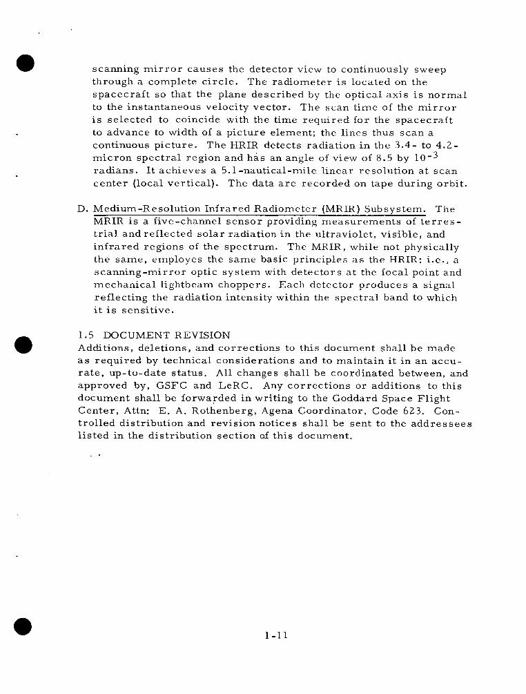
scanning m i r r o r causes the detector view to continuously sweep through a complete c i rc le . spacecraf t so that the plane described by the optical axis is no rma l to the instantaneous velocity vector. The scan t ime of the m i r r o r is selected to coincide with the time required for the spacecraf t to advance to width of a picture element; the l ines thus scan a continuous picture . The HRIR detects radiation i n the 3 . 4 - to 4 . 2 - micron spec t ra l region and has an angle of view of 8.5 by radians. I t achieves a 5.1 -nautical-mile l inear resolution a t scan center ( local ver t ical) .
The radiometer is located on the
The data a r e recorded on tape during orbi t .
D. Medium-Resolution Inf ra red Radiometer (MRIR) Subsystem. The MRIR is a five-channel s enso r providing measurements of t e r r e s - t r i a l and reflected so la r radiation i n the ultraviolet , v is ible , and in f r a red regions of the spectrum. The MRIR, while not physically the same , employes the same basic principles as the HRIR: i.e., a scanning-mirror optic sys tem with detectors a t the focal point and mechanical lightbeam choppers. Each detector produces a signal reflecting the radiation intensity within the spec t ra l band to which i t i s sensitive.
1.5 DOCUMENT REVISION Additions, deletions, and correct ions to this document shal l be made as required by technical considerations and to maintain it in an accu- r a t e , up-to-date s ta tus . approved by, GSFC and LeRC. Any correct ions or additions to this document shall be forwarded in writing to the Goddard Space Flight Center , Attn: E. A. Rothenberg, Agena Coordinator, Code 6 2 3 . Con- t rol led distribution and revision notices shall be sent to the addres sees l is ted in the distribution section of this document.
a A l l changes shal l be coordinated between, and
1-11
SECTION I1
MISSION REQUIREMENTS AND RESTRAINTS
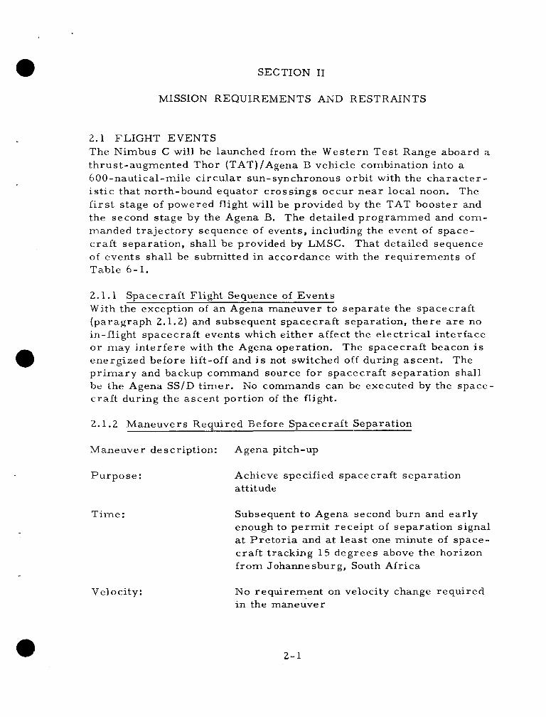
2.1 FLIGHT EVENTS The Nimbus C will be launched from the Western Tes t Range aboard a thrust-augmented Thor (TAT)/Agena B vehicle combination into a 600-nautical-mile c i rcular sun-synchronous orbi t with the charac te r - i s t ic that north-bound equator crossings occur near local noon. The f i r s t stage of powered flight will be provided by the TAT booster and the second stage by the Agena B. manded t ra jectory sequence of events, including the event of space- c raf t separation, shall be provided by LMSC. of events shall be submitted in accordance with the requirements of Table 6-1.
The detailed programmed and com-
That detailed sequence
2.1.1 With the exception of an Agena maneuver to separate the spacecraft (paragraph 2.1.2) and subsequent spacecraft separation, there a r e no in-flight spacecraft events which either affect the electr ical interface o r may interfere with the Agena operation. The spacecraft beacon is energized before lift-off and is not switched off during ascent. p r i m a r y and backup command source for spacecraft separation shall be the Agena SS/D t imer . c ra f t during the ascent portion of the flight.
Spacecraft Flight Sequence of Events
The
No commands can be executed by the space-
2.1.2 Maneuvers Required Before Spacecraft Separation
Maneuver description: Agena pitch-up
Purpose :
Time:
Velocity:
Achieve specified spacecraf t separation attitude
Subsequent to Agena second burn and ear ly enough to pe rmi t receipt of separation signal a t Pre tor ia and a t l eas t one minute of space- craf t tracking 1 5 degrees above the horizon f rom Johannesburg, South Africa
N o requirement on velocity change required in the maneuver
2- 1

Agena attitude: (a t instant of spacecraf t separat ion)
Angular Requirement Angular Tolerance
Roll 0 degrees Pitch 90 degrees Yaw 0 degrees
Roll * 5 degrees P i tch *15 degrees Yaw f 5 degrees
Rate Requirement Rate Tolerance
Roll 0 deg j sec Roll *0.3 d e g l s e c Pi tch 0 deg/sec P i t ch *0.3 d e g l s e c Yaw 0 deg l sec Yaw *0.3 d e g f s e c
After spacecraf t Separation, an Agena r e t r o maneuver is required to a s s u r e a minimum m i s s distance of 500 feet between the Agena and spacecraf t in all orbi ts throughout a 1-year period.
Agena attitude requirements a t the instant of spacecraf t separation a r e predicated on the ability of the spacecraf t to achieve acceptable post- separation stabilization. at the instant of spacecraf t separat ion should not be considered in- dependent of the requirements for acceptable post-separat ion dis tances between the spacecraf t and Agena. post-separation distance and f rom experience gained f rom the Nimbus -A program, factors influencing separat ion distance such as pitch attitude of the Agena, delay between t ime of Agena shutdown and spacecraf t separat ion to preclude adverse tail-off effects , orientation of Agena af ter separation, and forcible r e t r o of the Agena should be carefully considered. velocity of 4 feet per second relative to the Agena.
The range of permiss ib le Agena att i tudes
F r o m the viewpoint of acceptable
Springs in the spacecraf t adapter produced separation
2.2 OPERATIONS REQUIREMENTS
2.2.1 Launch Conditions
a. Range of launch t imes: The Nimbus C mission requi res a 600-nautical-mile c i rcu lar sun-synchronous orbi t with the character is t ics that north- bound equator c ross ings occur within 32 minutes of local noon (Local mean so lar t ime be- tween 1128 and 1232 hours) .
b. Launch date: F i r s t quar te r of 1966
2 - 2

c. Launch period: Not applicable
d. Other res t ra in ts : None
2.2.2 Trajectory Requirements (Separable Spacecraft, Ascent Phase )
1 . Inclination angle: The inclination of the orbit plane i s defined by the requirement that the precession ra te of the orbi t plane shall match the apparent regression ra te of the mean sun within 0.082 degrees pe r day.
2. Orbit eccentricity: Maximum acceptable apogee and perigee difference i s 28 nautical miles.
t 40 3. Mean orbi t altitude: 600 -20 nautical mi les
4. Position of f i r s t perigee: N o requirement
5. Time of f i r s t perigee: Consistent with launch window
6. Other controlled mission pa rame te r s : None
2.3 TRACKING, COMMUNICATIONS, AND CONTROL REQUIREMENTS 'There a r e no Nimbus C program-peculiar requirements for acquisition of te lemetry data disassociated from the requirements for data acqui- sition specified in paragraph 3.5. vehicle commands and control communications with the spacecraft .
0 There a r e no requirements for launch
2.4 SPACECRAFT FLIGHT OPERATIONS AND COMMUNICATIONS There a r e no launch vehicle system requirements for spacecraft data acquisition o r processing.
2 -3

SECTION I11
DESIGN REQUIREMENTS AND RESTRAINTS
3.1 CONFIGURATION DEFINITIONS
3.1.1 Spacecraft The genera l a r rangement of the spacecraf t is shown i n Figure 3-1, which includes dimensions and gives locations and types of the principal equipment. sha l l be shown in the official mechanical interface drawing.
Details which govern the interface design of the spacecraf t
3.1.2 Spacecraf t Support Structure (Adapter) Figure 1-4 shows the general arrangement of the spacecraf t adapter . The adapter , furnished by GSFC, sha l l be used t o provide volume b e - tween the spacecraf t and the Agena B forward equipment rack into which GSFC/GE -furnished spacecraf t p r e -launch tes t and calibration equipment i s installed. It is the responsibility of GE/DAC to provide detailed design, construction, and acceptance testing of this adapter . GE shal l provide and incorporate in interface design those devices necessa ry to effect spacecraf t separation f rom the launch vehicle and effect a relat ive velocity of four (4 '~2 ) feet pe r second between the spacecraf t and i t s adapter . Design of this separat ion interface i s a joint GSFC/GE/DCA undertaking. Details which govern the interface design shal l be shown in the official mechanical interface drawing.
3.1.3 Aerodynamic Shroud The genera l arrangement of the shroud i s shown in Figure 1-1, which includes principal dimensions and a c c e s s doors. be shown i n the official mechanical interface drawings required by paragraph 3.1.4.2. Only one flight shroud need be provided for the Nimbus C program.
Specific details shall
LMSC/DAC sha l l provide to GSFC an engineering model shroud to be used for mechanical c learance checks, R F t ransmiss ion checks, and simulation of on-pad operational checks in accordance with the requi re - ments of Table 6-1. but shall be identical within manufacturing and stack-up tolerances to Nimbus flight hardware in all aspects which affect: mechanical and e lec t r ic a1 int e rf ace s , as c e rt aining c r i t ic a1 s ta t ic c learance s between shroud and spacecraf t /adapter , resul ts of R F t ransmiss ion t e s t s , a c - c e s s to spacecraf t /adapter , and handling of the shroud system.
This shroud need not be qualified flight hardware,
In
3 - 1

3 - 2
satisfying this requirement, mock-up of shroud instrumentation i s ac - ceptable. fo r the Nimbus A program is acceptable.
Up-dating of the engineering model shroud provided to GSFC
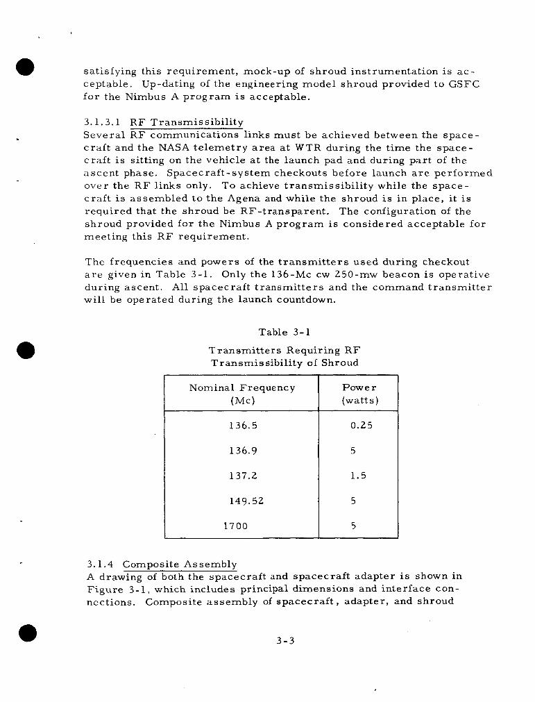
3.1.3.1 R F Transmissibi l i ty Several R F communications links must be achieved between the space- c raf t and the NASA telemetry a rea at WTR during the t ime the space- c raf t i s sitting on the vehicle at the launch pad and during par t of the ascent phase. over the R F links only. To achieve t ransmissibi l i ty while the space- c ra f t is assembled to the Agena and while the shroud is in place, i t is required that the shroud be RF-transparent. The configuration of the shroud provided for the Nimbus A program i s considered acceptable for meeting this R F requirement.
Spacecraf t -system checkouts before launch a r e performed
The frequencies and powers of the t r ansmi t t e r s used during checkout a r e given in Table 3-1. during ascent. will be operated during the launch countdown.
Only the 136-Mc cw 250-mw beacon is operative All spacecraft t ransmi t te rs and the command t ransmi t te r
Table 3-1
Transmi t te rs Requiring R F Transmissibil i ty of Shroud
Nominal F r e que nc y (Mc)
136.5
136.9
137.2
149.52
1700
Power (watts)
0.25
5
1.5
5
5
3.1.4 Composite Assembly A drawing of both the spacecraft and spacecraf t adapter is shown in
-
Figure 3-1, which includes principal dimensions and interface con- nections. Composite assembly of spacecraf t , adapter, and shroud
3-3

attached to the Agena shal l be shown in detai l in the official mechanical and e lec t r ica l interface drawings. schedule f o r the official mechanical and e l ec t r i ca l in te r face drawings a r e presented in the following paragraphs.
The bases , scope, and associated
3.1.4.1 Design Specification Control Drawings GSFCIGE shall generate and maintain mechanical and e lec t r ica l design specification control drawings for spacecraf t and adapter . tr ibution shall be i n accordance with the requirements of Table 6-1. Revisions shall be furnished automatically to the recipients of the init ial distribution. These drawings shal l show engineering detail of interface hardware design to permi t c r o s s design and the rma l studies with spacecraf t /adapter , shroud, and Agena, including, but not l imited to, the following:
Initial dis -
Identification, location, and orientation of e lec t r ica l connectors, including connector pin assignments
Identification, location, and orientation required fo r a l l space - craf t /adapter mechanical and e lec t r ica l hardware access for mating o r se rv ice when assembled with the launch-vehicle system
Envelope of the spacecraf t /adapter ex t remi t ies , including adverse manufacturing assembly and alignment to le rances (no-load condition)
Lateral load-deflection charac te r i s t ics for cantilevered space - craf t /adapter in t e r m s of inches deflection per unit s ta t ic l a t e ra l acceleration (g)
The designation, location, orientation, and dimensions of those elements of the spacecraf t and adapter which a r e determined by GSFC/GE to be tempera ture-cr i t ica l ; designation of mater ia l s , surface coatings, absorptivit ies, emiss iv i t ies , and, i f not com- monly available, ma te r i a l thermal proper t ies . These data a r e required to permit LMSC performance of t he rma l response analyses specified in paragraph 4.3.3.
3.1.4.2 LMSC shall generate and maintain official mechanical and e lec t r ica l interface drawings. the requirements of Table 6-1.
Official Mechanical and Elec t r ica l Interface Drawings
Initial distribution shal l be in accordance with Revisions sha l l be furnished automatically
3 -4

to the recipients of the init ial distribution. t r i ca l interface drawings shall show engineering details of interface hardware design to permit c r o s s design studies with the spacecraf t / adapter, shroud, and Agena, including, but not limited to, the following:
The mechanical and e lec-
0 Identification, location, and orientation of e lec t r ica l interface connectors including connector pin assignments; location, length, and s ize , where applicable, of conductors and connector pins which compose the blockhouse-to-Agena/adapter interface circui ts
0 Mechanical assembly dimensions and tolerances
0 Tables of net c learances in cr i t ical locations between spacecraf t / adapter / shroud for c r i t i ca l loading conditions using static and dynamic deflections with a 1.25 factor of safety applied to a l l deflections. measurements of the shroud(s) to be used for the Nimbus C flight. a s the shroud insulation (and insulation fas teners ) , shroud in- strumentation and any Nimbus C mission peculiar shroud modifications.
The shroud dimensions shal l be based on the physical
The shroud dimensions shall account for such factors
0 Identification and location of a l l interface access ports in the shroud and the adapter
0 Identification, location, and electr ical wiring details of a l l Agena/ shroud circui ts including instrumentation and separation equip- ment which require connections through the spacecraft adapter.
3.2 MASS AND STIFFNESS PROPERTIES
3.2.1 Mass Proper t ies Current weight for the spacecraft and adapter shal l be reported by GSFC on o r about the tenth day of each month. The GSFC monthly report is intended to permit LeRC assurance that co r rec t values a r e used for t ra jectory guidance. able for initial planning. data shall be updated when significant changes occur.
The propert ies l is ted below are applic- Moment -of - inertia and center -of -gravity
3 - 5

Weight (e s t imat ed value)
Spacecraft 945 lb Adapt e r 80 lb
Center-of-Gravity
Along rol l axis::: (measured f rom pitch axis, inches)
Along yaw axis, station
Along pitch axis (measured f r o m rol l axis , inches)
2 Moments -of-inertia (slug -in )
Ioy pitch
Product of iner t ia (slug - in ) 2
Roll -yaw Roll - pit ch Yaw -pitch
Launch Configuration With Adapter
(Paddles Folded)
-0.34
199.30
0.03
34512
13637
33621
901.5 -35.5
-169.3
Orbit Configuration
Without Adapte I
( Paddle s Open)
0.35
196.86
0.01
34295
14674
2981 1
-106.5 -34.4
-178.1
3.2.2 Stiffness Proper t ies GSFC/GE shall provide the vibration modes for the cantilevered space- craf t /adapter , including lateral and longitudinal modes. plied under this requirement shal l be identified for Nimbus C use. Submittal of these data shal l be in accordance with the requirements of Table 6-1.
All data sup-
c
3-6

3.3 MECHANICAL INTERFACE REQUIREMENTS a 3.3.1 Alignment and Tolerance There a r e no launch vehicle alignment tolerances imposed by the space- c raf t /adapter beyond that presented i n a subsequent section on match- mate . It shall be the responsibility of LeRC t o inform GSFC of any spacecraft/adapter-Agena alignment necessary to a s su re acceptable flight charac te r i s t ics of the launch vehicle.
3.3.2 Matchmate A se t of matched tools, shown pictorially in Figure 3-2, shal l be used to achieve mating surfaces of the spacecraft adapter and the Agena vehicle. mission shall be used for the Nimbus C mission.
The matchmate tool furnished to LMSC for the Nimbus A
The specification and procedures for initial surfacing of the spacecraft adapter and Agena vehicle using the matchmate tools shall be identical to those applicable to initial surfacing for the Nimbus A mission (LMSC Spec. M30086). procedures for Nimbus C in accordance with the requirements of Table 6-1.
LMSC shall issue the matchmate specifications and
Following surfacing the spacecraft adapter and Agena using the match- mate tools, GE shall deliver the flight spacecraft adapter to LMSC to substantiate that all specifications for acceptable mate of flight hardware have been satisfied. f ixture simulating the Nimbus C spacecraft cr i t ical clearance points shal l be used with the flight shroud during this matchmate of adapter and Agena. Any necessary modification to the Nimbus A adapter s t a - bilization and spacecraft f ixtures to make them representative of the Nimbus C spacecraft shall be accomplished by GE in accordance with Table 6-1. include sufficient hardware to define the location of cr i t ical shroud/ spacecraf t /adapter clearance points and to permit checkout of space- c raf t service functions which require shroud access doors. m a t e of flight hardware and simulated spacecraft shall occur p r io r to the flight qualification testing of the Nimbus C spacecraft a s set forth in Table 6-1.
a An adapter stabilization fixture and spacecraft
The stabilization fixture (GE Drawing 237R460-ST-1) shall
This match-
The foregoing represents the total requirements for scheduled match- mate checks using the matchmate tools. An additional assessment of matchmate of the flight adapter and the Agena w i l l be achieved when the prototype spacecraft is mated to the Agena during WTR prototype
3 -7

3-8

spacecraft exerc ises . If g ross mismatch between the prototype adapter and Agena a r e disclosed, check of the Agena with the MT-1 tool may be required. for such emergency. match between the adapter and the erected launch vehicle shall be a s specified for the Nimbus A launch, that is, gaps in the Agena/adapter interface of up to 0.020 inches a r e acceptable f rom the standpoint of init ial spacecraft stabilization provided bolt -pad clearance does not exceed l ip clearance by m o r e than 0.006 inches. ance between bolt-pad and l ip is exceeded, reshimming is indicated. The foregoing specification of acceptable gap during final mating of flight hardware a t WTR shall not be construed as a relaxation of initial matchmate specification requirements which a r e considered necessary to achieve acceptable launch base final mating.
LeRC shall a s s u r e the availability of the MT-1 tool at WTR The spacecraft requirements fo r acceptable
If the 0.006 inch to le r -
3.4 ELECTRICAL INTERFACE REQUIREMENTS
3.4.1 Spacecraft/Adapter With the exception of spacecraft separation squib activation by the launch vehicle e lectr ical sys tem (paragraph 3.5.3), there a r e no launch- vehicle e lectr ical-system requirements applicable to the spacecraf t / adapter interface. arat ion plane and no electr ical disconnect between the spacecraf t and i t s adapter.
There shall be no wires a c r o s s the spacecraf t sep-
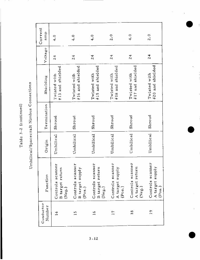
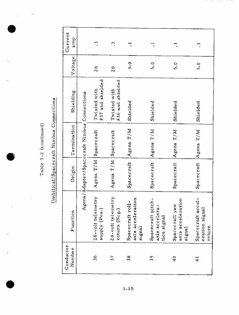
3.4.2 Specific engineering details of the electr ical interface between the Spacecraft system and the launch vehicle sys tem shall be specified in the GSFC/GE design specification control drawings required by pa ra - graph 3.1.4.1. and two connectors f rom spacecraft adapter t o shroud. shal l be identical to that used for the Nimbus A Program. be th ree connectors between th.e spacecraft adapter and the Agena. Table 3-2 lists applicable spacecraft functions and other e lectr ical interface data.
Spacecraft / Adapter / Launch Vehicle System
There shall be one connector f r o m spacecraf t to shroud These connectors
There shall
3.5 ELECTRICAL REQUIREMENTS
3.5.1 Instrumentation Table 3 - 3 l i s t s telemetry and instrumentation requirements imposed on the Agena system by the spacecraft.
3 - 9

ffl e 0 .d o V
c 0 u $
ffl 3 P
N E c : g
M c .d
2 2 0
cn
c M .d
.d
6
0
F
0 0
r- t-r
m 0
0 0
cc
m 0 0 Ln
N
m n m n m m n m m n m m
L n
9 d
2 0 z
Q c
o G w r" r" W c,
cd cd Id cd cd k k k k k V V V u 0 a, a, a, a, Q V V V V V cd cd Id Id cd a a a a a cn cn cn UI r/l
c, w Id k k 0 a,
a a, cd V
cd a Cn
c,
z I4 d d d cd Id cd Id
V V u V .d A
.d A
.d -I
.d A . . . . :A ;A .d .d
P P P P E E E E 3 5 5 3
P-l cd V
P
.d 4 .d
E 3
4 cd V
P
3
.d I+ .d
E
0 0 - e a,' I E o O cdpc u d -
4 N m * In 9 r-
3 - 1 0

m I= 0 .rl c, u
a, M rd
0 c, I+
>
M I= .rl
a, 2 a,
v)
c 0
rd c
.rl c,
3 k a, b
d M
.rl
.rl
5
c 0 .rl c, : cz
m m m hl
m 0
In
a, c, P rd a 4
k k k k k a, c, a rd a 4
a, c, a rd -d 4
a, a rd
c,
z a 3 0 k A cn
4 rd u
.A 4
b" E 3
4 rd u .rl I+
3 E 3
4 rd u .rl I+ .rl
P
D E
4 Id u .rl
2 P
D E
' 0 3 - 1 1
v) r: 0
V a,
.r( c,
e c! 0 u 9 P v)
E 2 c, 4-(
rd k V a, V cd a
zn
rd V
\ 4
.rl 4
5 E 9
0 0 0 0 0 0
4 4 d N 4 N
a a a a 9
a 0
9 0 k k
5 k
0
s zn c k
zn c zn c m
3 0 k c zn
a 3 0 k c zn
" rd V
P
.rl 4 .r(
E 5
" rd V .rl 4 s E 5
4 rd 0
P
.rl 4 .rl
E 5
" cd V
P
.rl 4 .rl
E 5
4 rd V
P
9
.rl " .r(
E
4 rd V
P
5
.rl 4 .r(
E
3 - 1 2

h
-a a, 9 c G 0 u nl
I cr)
a, P rd b
.d c,
Y
d
rn
.rl c, u 2 c 0 u 5 e 01
E 2 c, w rd k V a, u rd a VI
rd u
P
5
\ d
.r(
d .rl
E
c 0
rd c
.r( c,
-2 k a, b
c M .rl
.rl
6
c 0
.r( c, U e 3 6(
k O k ” a , YP a E 8 g u
N 0 0
N
4
N 0 0 0
4 d 0 0 0 0
4
0 0 0
4
0 0 9 9 9 9 * d -I N
* N
a a a a, a, Q)
W a a
a 5 0 k c VI
” CI ” rcl w W rd d d k k k U u U a, Q) a, u u u rd Id rd a a a Cn rA m
c, w
rd k u a, u ld a VI
c, W rd k U a, u Id a VI
” c, w w d rd k k U U a, a, u V rd rd a a VI VI
k a, a rd
c,
:
d d d d U
P
.r(
d .VI
E 5
V .rl d
E E 5
4 rd U .rl rl
2 E 5
d rd U
P
.rl d .rl
E 5
.rl d
2 E 5
d cd U
.r( d
2 E 5
k a, k 3 m m a, k a 3 c d d ” r d m e
M m
8 .r(
0 4 N rr) * In 9 r- nl N N N hl nl N N
3 - 1 3

01 c 0
V
.rl +
$ c 0 u =1 P
m
E 2 c, w rd k V a, V rd a cn rd V
P
5
\ 4
.rl 4 .d
E
L n 0 0 0 Ln 0 0 0
4 4 N d 4 4
* * * * * N N
* N N N N N
a, : : c z z s c, + w w + w w c, w c, w w rd rd rd cd rd rd
k k k k k k k V V V V V v a , a, a, a, a, a, a , + V V V rd Id Id a a a a cn VI cn VI
rd V : % a $ 2 : VI
d cd V
.r( 4
2 E 5
4 rd V
.rl
2 P
5 E
4 rd V
P
.r(
d .d
E 5
I k a, +
a, k Id a cn
Q) k rd a cn
Ln g r . 7 a3 m 0 4 N rr) N N rr) m cr) cr)
3 - 1 4
h
W
c c 0 U
N
M
a,
rd
s .d c,
Y
I
s b
m c 0
V
.rl c,
$ c 0 u 3 P (0
E 2 c, w rd k u a, u (d a VI
rd u
\ 4
.rl 4 z E 3
c M .rl
.rl
0"
c 0
u c
.rl c,
cz k O k * a ,
a E 2 2 u
M m d 4 4 m
0 0 0 0
a3 rx) 4 m In m N N
5 a P) a, a
- m 3
c, c, c, c, W w w w
rd cd rd rd
u u u u a, a, a, a, u U u U nf rd rd cd a a a a
z \
: z r n b I3 k k k k
; 2 a \ \
Id e a, @ a ,
? VI VI VI cn a . " $ -4 1
3 - 1 5

h a a, 9 c c 0 V
N I
M
a,
rd
.r( c,
v
z E-r
m c 0
V .r( c,
$ c 0 u 9 P m
E !2 c, w rd k V a, V rd a rn
cd V
P
\ d
.r(
d .r(
E 5
c 0
rd c
.r( c,
2 k a, b -
c M .r(
.r(
6
0 0 0
co co Ln 4 In m N N N
h a
c c 0
s .r( c,
a a, a,
.6, .2 *$ 5
a Q)
a, 3 % 2 2
-a, c c 0 u
e a
2
2 \
k k k a, a, c, c,
a, k k b
a, a a a
Id a, ld rd rd a c, c, $ 2
E d : 9 4 P 2 a 2 :
- k a, c, a x 0
h .r(

h
W a, 5 c .rl c,
g V
N
rc)
a,
rd
Y
I
3 b
m c 0
0
.rl c,
2
; E 2
e 0 u
P
c, w rd k U a, U td a m
rd V
\ l-4
.rl I+
b" E 5
a, M rd
0 c, l-4
>
0 0 0 0
In In In In
0
In
Q) m m a) N N N N
co N
h -a
- 2 0 u (0
5 P E z c, -W
k a, a rd
c,
2
k 0)
a rd
+.,
2
k a, c, a rd
P
k a, a rd
c,
2 a \ m
a \
m a \
m
c, -a rd
2 2 7
\
a,
I a
3 - 1 7

k a, c, a rd
2 c, a
\
VI
k
a rd
W
fJ c a,
-a,- c,
4 1
7
3 - 1 8

I a,
r d l d a & m u
V Z I a,
r d r d a k m u
v *
x k 0 rd c,
h k 0 Id a FI
c,
5
h k 0 rd a G
c,
3
h k 0 c,
a c
a, v)
0 a : PI
0 I u
U a + In
I 0
U a 3
u a 3
m I
0
U a 3
m 0 I
VI I
0
I
3 - 1 9

3.5.2 Spacecraft Power to be Supplied by Launch Vehicle Three accelerometers mounted on the spacecraf t and one vibration transducer mounted in the spacecraf t adapter requi re launch vehicle t28v regulated d i rec t current. Power f o r the t ransducers on the space- c raf t shall be supplied through the adapter / shroud/ spacecraf t c i rcui t and interrupted a t t ime of shroud separation. Power for the t ransducer in the spacecraft adapter is supplied direct ly through the adapter/Agena inte rfac e.
Four squibs employed a t the spacecraf t /adapter separation plane for separation of the spacecraf t f r o m its adapter shall be activated via launch vehicle switching. peak current of 5 amperes represents the nominal e lectr ical requi re - ments fo r each of the four squibs. requirements.
An impedance of 0.2 ohms, 28vdc, and a
Table 3-4 summar izes these
3.5.3
There are no requirements for Agena programming of events in the spacecraft.
Switch Loading for Spacecraft Functions Activated by Launch Vehicle
3.6 ENVIRONMENTAL REQUIREMENTS
3.6.1 Spacecraft Thermal Environment Table 3-5 is a summary of spacecraf t thermal c r i t i ca l components and associated thermal limits applicable during launch through injection. Bulk thermal l imits between which the spacecraf t mus t be maintained a r e 10°C ( 5 0 ° F ) and 45°C (113°F). of spacecraft components together with designation of all thermal cr i t ical components shall be provided in accordance with the requirements of paragraph 3.1.4.1. thermal cri t ical components. I tems 1 through 7 of Table 3-1 will r e - ceive direct thermal radiation f rom the shroud during launch. other components l isted may be considered as not significantly affected by shroud heating.
Data applicable to thermal response
Figure 3-1 presents general locations of cer ta in
The
Detailed time his tor ies of spacecraft power dissipation a r e dependent on detailed spacecraft sys tem t e s t procedures which remain to be de- veloped. spacecraft/vehicle launch configuration throughout launch countdown (approximately 8- 10 hours) is representative. of 420 watts over an interval of 30 minutes may resu l t during on-pad checkout. out the ascent t ra jectory is representative.
However, an average power dissipation of 200 watts in the
Peak power dissipation
A constant spacecraf t pbwer dissipation of 160 watts through-
3-20

Table 3-4
Spacecraf t Power Supplied by Vehicle
I Spacecraft
Function
Spacecraft yaw axis accelerat ion
Spacecraft pitch axis accelerat ion
Space c raf t roll axis accelerat ion
Spacecraft separatior; pyrotechnic s
Spacecraft vibration (adapter)
t28v Un r e gul a t e d
Load
20 amp
each) (5 amp
Duty Cycle
1 sec. max.
Load
100 mil amp
100 mi l amp
100 mil amp
100 mil amp
t28v Re g ul a t e d
Duty Cycle
Continuous unti shroud sepa ra - tion
Continuous unti shroud sepa ra - tion
Continuous unti shroud sepa ra - tion
Continuous, not required a f te r S I C separat ion
3-2 I

Table 3-5
Nimbus C Temperature-Cri t ical Components
Description ~~~~~
1. Yaw axis coarse sun senso r s
2. Horizon scanner case & window
3. Stabilization & control sys tem upper surface
4. Solar a r r a y sun senso r s
5. Sensory subsystem, upper surface
6. Separation devices (bolt cut ters)
7. Beacon/PCM antenna
8. Solar platform aluminum channels
9. Solar platform
10. Solar platform transit ion section
11. Solar platform motor drive casing
12. Solar platform switch
13. Solar paddle latch line
Max. Temp. (OF 1
22 1
14 1
300
22 1
300
77
160
140
140
140
140
140
140
Min. Temp. ( O F )
-58
3
Not cr i t ical
- 58
Not c ri t ic a1
5
-2 3
- 112
-112
-112
23
2 3
23
3-22

3.6.2 On-Pad Spacecraft Cooling The flight spacecraft will be mated to the Agena on R-4 day; R-0 day being the day of countdown initiation. c r a f t shall be provided a controlled environment.
At all t imes thereaf ter the space-
Spacecraft thermal character is t ics and the varying levels of e lectr ical heat dissipation during on-pad checkout require air conditioning of the shroud a t a l l t imes f rom shroud installation to lift-off. t ro l of spacecraft t empera tures within the bulk temperature limits, air-conditioning shall be provided which will supply air to the shroud inlet and satisfy the following conditions:
To pe rmi t con-
0 Temperature: variable *2"F f r o m 5 0 ° F to 75°F
0 Flow rate: variable *5 pounds p e r minute f rom 30 pounds pe r minute to a maximum of 6 0 pounds per minute
0 Humidity: relative humidity not exceeding 4 5 percent
0 Filtration: preclude passage of par t ic les equal to o r grea te r than 50 microns.
Environmental control of the gantry greenhouse inter ior shall be r e - quired to maintain an inter ior temperature of 60°F *5" and an average relative humidity of 45 percent. Cracks and holes in the greenhouse ex ter ior surfaces shall be closed. Port ions of the greenhouse which may be opened and closed shal l be sealed, when closed, to permi t a positive differential p re s su re inside the greenhouse to be maintained with air-conditioning. Conditioned air supplied to the greenhouse in- t e r io r shall be fi l tered to a s su re exclusion of 90 percent of a l l par t ic les g rea t e r than 50 microns f rom that air.
3.6.3 Contamination Control There shall be no contamination, within the limits specified below, of spacecraf t s enso r s f rom ground cooling, pyrotechnic sources , vehicle fuel venting, mater ia l outgassing, o r other launch vehicle system. Means shall be provided to sea l the spacecraf t adapter cavity f rom vehicle air-conditioning. must be accomplished by means which a s s u r e non-contamination of the space c raft.
Any retro o r other maneuver of the Agena
It is required that optical t ransmission lo s ses resulting f rom contami- nation shall not exceed 2%. This l imit shall apply to all regions of the
3 - 2 3

spec t rum over which the sys tem is sensitive. not cause wear o r abrasion on any optic system. t icle l imits established by shroud air-conditioning fi l tration requi re - ments , contamination shall be l imited to thin film coatings such a s might result f r o m condensation of products of outgassing. applicable spacecraft subsystems and regions of the spectrum over which they a r e sensitive a r e l is ted below:
The contamination shall Within the solid p a r -
The various
TV cameras 480-850 mil l imicrons H RIR 3.4-4.2 microns MR IR Horizon sensors 12.0 - 18.0 microns Solar cel ls 0.4-1.1 microns Sun sensor 0.4-1.1 microns
0.2 - 30.0 microns
3.6.4 Sterilization There a r e no steri l ization requirements applicable to the Nimbus C program.
3.6.5 Applied Loads There a r e no requirements fo r shaped vehicle t ra jec tory necessitated by spacecraft loads cri teria.
3.6.6 Acoustic Noise The Nimbus C project requires that the "wet pad" capability of W T R pad 75- 1 - 1 be furnished to minimize the acoustic noise level.
3.6.7 Electromagnetic Environment
A. Conducted Interference. Spacecraft sys tems checkouts before launch a r e performed over R F links only. c i rcui ts for functions such as bat tery charging, a s specified in a subsequent section, there a r e no specific design requirements beyond usual acceptable launch pad electr ical wiring practices. a joint spacecraft and vehicle sys tem responsibility to monitor cog- nizant systems for interference caused by switching o r R F t r a n s - mission performed during scheduled integrated tests.
F o r spacecraf t hard-wire umbilical
It shall be
B. RFI Tests. During the mock countdown with the prototype spacecraft , the RFI tes t used for the Nimbus A p rogram wherein tracking r a d a r s and spacecraft command t ransmi t te r a r e beamed a t the spacecraf t shall be repeated for the Nimbus C program. program, spacecraft squibs shall be simulated during this test.
As in the Nimbus A
3-24

C.
D.
E.
F.
G.
H.
Radiated Interference. other than spacecraf t t ransmit ters .
There is no Nimbus C radiating equipment
Spacecraft Transmi t te r Identification (Beacon). identification of spacecraft t ransmit ters .
Table 3 -6 provides
Transmi t te r Frequency Spectra. not available fo r incorporation in this document. to obtain these data.
Spacecraft t ransmi t te r spec t r a a r e GSFC has no plans
Spacecraft Wiring Design. Details of spacecraft wiring design ap- plicable to interfaces with the vehicle sys tem shall be provided in accordance with the requirements of paragraph 3.1.4.1. the following information applicable to spacecraft design is provided:
In general ,
0 Ground system: multiple point
0 Extent of conductor shielding used: power, signal, and pyrotechnics
0 Ground re turn system employed: signal, power, pyrotechnic, and shields employ conductors, whereas equipment c a s e s employ spacecraft structure.
0 Electr ical bonding: copper braid
Magnetic Materials. l imitations on use of ferromagnetic mater ia l in vehicle structure.
There a r e no spacecraft requirements for
Nuclear Radiation. s p ac e c raft.
There is no nuclear radiation f rom the
3.7 CLEARANCE REQUIREMENTS
3.7.1 Static Clearance Determination of static clearance between the spacecraft , spacecraf t adapter , and the shroud shall be in accordance with the requirements of paragraphs 3.1.4.1 and 3.1.4.2, and i s intended to lead to de te rmi- nations of c learances which properly account for both static and dy- namic sys tem deflections. c learances previously se t forth a r e a l so intended to substantiate that no s ta t ic o r dynamic interference exists between the spacecraf t /adapter and the shroud under any static o r dynamic launch condition.
The requirements fo r determination of
3-25

v U
.d w m o m
d 0 .rl c, d V -4 w .A c, c a, a, k Q) c, c1
-2 m G d k b c, w cd k V a, V cd a m
0 3 k S + a M U
5 a 3 a d cd a
.rl V r: 3 3 +
V
m 3
0 0 6-4 F F 4 4
\d m 4
m c, c,
? $ 4
m c, c, d
m 3
m c, c, cd
m 3
3 - 2 6
3.7.2 Dynamic Clearances As outlined in paragraph 3 . 7 . 1 , requirements have been specified for determination of static and dynamic clearances.
3.8 SEPARATION REQUIREMENTS AND RESTRAINTS
3.8.1 Shroud There a r e no peculiar requirements o r res t ra ints . cluding all components of the shroud sys tem) shall not physically in te r fe re o r have other adverse affect on ei ther the spacecraf t /adapter o r launch vehicle during o r a f te r shroud separation.
The shroud (in-
3.8.2 Spacecraft No hardware i tems of the spacecraft adapter o r vehicle sys tem shall remain with the separated spacecraft.
3 -27

SECTION IV
PROGRAM ANALYSIS, TEST AND DOCUMENTATION REQUIREMENTS
4.1 GENERAL The requirements of this section a re intended to satisfy project needs fo r technical information necessary f o r overall evaluation of the effects of vehicle - sys tem character is t ics , configuration, and schedules upon corresponding spacecraf t technical considerations. It is c lear ly the responsibility of LeRC to coordinate the performance of vehicle sys t em analyses and demonstration of vehicle sys t em tes t s , to receive con- t r ac to r documentation, and to forward that documentation and all related technical information to GSFC. In this respect , i t shal l be the respon- sibility of LeRC to a s s u r e that changes in vehicle-system charac te r i s t ics , configuration, and schedules which affect the requirements of this doc- ument, o r tes t s , analyses, and reports obligated in support of these requirements , a r e promptly reflected in document o r t e s t revisions, o r proposal for revision, wherever applicable.
4.2 TEST REQUIREMENTS
4.2.1 General Subsequent paragraphs of this section 4.2 presents t e s t requirements which may be unique to the Nimbus C spacecraft. Other general t e s t requirements which require joint GSFC and LeRC planning a r e to be included in an "Interface Plan and Schedule" as discussed in paragraph 4 . 3 . a r e not l imited to, the following:
The general tests considered applicable to Nimbus C include, but
0 Shroud separation tests: Required fo r Nimbus C shroud if shroud changes have been incorporated which affect t es t resu l t s obtained for Nimbus A
0 Space c raf t / adapte r / A gena / TAT ele c t r ic a1 compatibility and a l l sys tems t e s t s and detailed tes t procedures therefor: Applicable for either r ea l o r electrically simulated t e s t components
0 Spacecraft/adapter/Agena electr ical continuity tes t s and detailed t e s t procedures therefor : Applicable fo r either real o r e lec- t r ical ly simulated t e s t components
4- 1

0 Spacec raft /adapte r / Agena mechanical compatibility t e s t s and detailed tes t procedures therefor: electrically simulated t e s t components.
Applicable fo r e i ther rea l o r
0 Blockhouse-to-Agena umbilical wiring checkout
4.2.2 Following initial integration of launch-base procedures involving coor- dinated launch vehicle and spacecraft sys tem actions, a r ehea r sa l a t GE, Valley Forge , will be scheduled in accordance with Table 6-1 to evaluate procedures, acquaint spacecraf t and launch base personnel with the applicable equipment and procedures , and to a s s e s s the sched- ule to be assigned to the l a s t three days of launch activity.
Rehearsal of Integrated Tes t Procedures a t GE
The rehearsal , s imi la r to that performed for Nimbus A, will involve a Nimbus spacecraft with its adapter, an Agena forward equipment rack, the engineering model shroud of paragraph 3.1.3, and associated han- dling equipment. shroud f o r such use a s this rehearsa l were se t for th in paragraph 3.1.3. Similar requirements a r e se t for th he re for the Agena forward equip- ment rack; that is, it is required that LMSC accomplish all necessary modification to the Agena forward rack located a t GE to a s s u r e complete representation of the flight Agena in a l l aspects which affect mechanical and electrical interface, and handling of the shroud system. Any neces- s a r y modifications to the GE forward equipment rack shall be accom- plished in accordance with the schedule of Table 6-1.
Requirements for updating the engineering model
Rehearsal with the foregoing equipment, performed by spacecraf t and launch base personnel who will actually per form the tasks at the launch base, will be scheduled to include:
0 Briefing and orientation of attendees
0 Rehearsal of R - 4 day pad activity, p r imar i ly spacecraf t installa- tion on the Agena
Rehearsal of R-3 and R-2 day pad activity, p r imar i ly shroud installation and spacecraft checks
0 Rehearsal of R-0, p r imar i ly evaluation of spacecraf t in launch mode and concluded by overall review of r ehea r sa l
4 -2

Although launch base personnel such a s the shroud installation crew and supervisory personnel for all integrated activity a r e encouraged to attend for the full r ehea r sa l (approximately 4 days), the i r actual s e r v - i ce s could be l imited to rehearsa l of R-4 and R-3 i f necessitated by other considerations. Participating agencies are: GSFC, GSFC/GE, GSFC/GLO, GE, LeKC, LeRC/LMSC, LMSC (Sunnyvale), LMSC (WTR), DAC (Tulsa), DAC (WTR), A F (WTR).
4.2.3 Spacecraft /Adapter /Shroud/Agena Elec t r ica l Interface Tes ts Substantiation of acceptable e lectr ical interface between the spacecraft and launch vehicle sys tem requires cer ta in interface electr ical t e s t s before launch. Fo r the Nimbus C, these t e s t s a r e outlined below:
The Nimbus C flight adapter will be provided to LMSC Sunnyvale to participate in the matchmate of adapter t o Agena. matchmate, and in addition to the mechanical mating process , an e lec t r ica l check using the flight adapter, flight shroud and flight Agena will be performed. tes t will be to check electr ical continuity of applicable flight harnesses in the adapter, shroud, and Agena.
At the
The purpose of this e lectr ical
The Nimbus C flight adapter and an electr ical simulation of the spacecraft will be provided t o LMSC Sunnyvale to participate i n Agena sys tems t e s t s which involve provision of e lectr ical func- tions to o r through the spacecraft/adapter configuration. e lectr ical spacecraft simulator used at WTR for the Nimbus A program will be updated for this tes t and includes provision for simulation of spacecraf t e lectr ical loads. The purpose of this tes t will be to check applicable flight harnesses and Agena functions for transmitting the required e lec t r ica l power by proper commands.
The
The spacecraf t /adapter electrical s imulator and the flight spacecraf t /adapter will be provided a t WTR to be used in vehicle compatibility and systems t e s t s which involve provision of e lec t r ica l functions to or through the spacecraf t /adapter con- figuration. repeat the e lec t r ica l checks of (2 ) above, to a s su re that no changes in wiring o r no damage has occurred since performance of the LMSC Sunnyvale tests.
The purpose of these t e s t s will be to essentially
After final mate of the flight spacecraft/adapter to the Agena, a continuity check of the spacecraft separation circuit will be
4 - 3

performed f rom the point of spacecraf t separation squib connectors. It i s planned that this t e s t be performed identical to the c o r r e - sponding tes t per formed for Nimbus A. is to check continuity of final mate of the separation circuit . Also af ter final mate , e lec t r ica l checks of spacecraf t functions supplied through the Agena umbilical will be performed in the same manner performed for Nimbus A. tion of such umbilical c i rcui ts a s spacecraft battery charging, target light and scanner st imulator operation, and pneumatic system p res su re and temperature operation.
The purpose of this tes t
These include cer t i f ica-
4.2.4 R F Tests Spacecraft RF-transmission t e s t s with the gantry in place above the launch vehicle shall be made with spacecraf t and shroud in place on the Agena. signal strength reception at the Nimbus mobile ground station located at the spacecraft assembly building adequate for spacecraft subsystem ground equipment operation. An R F repeater capability on the gantry covering 136-137 Mc will be provided by GSFC/GLO for these tes ts . Spacecraft t ransmit ter data a r e provided in Table 3-6.
The purpose of this tes t shall be to substantiate acceptable
4.3 ANALYSIS AND DOCUMENTATION REQUIREMENTS
4.3.1 Interface Plan and Schedule LeRC shall prepare an "Interface Plan and Schedule" f o r a l l interface t e s t and documentation requirements which involve GSFC/GE hardware, personnel, o r technical information. This "Interface Plan and Schedule" shall define, where applicable, the objectives, general procedures , equipment, and schedules for each interface requirement. to technical efforts outlined in paragraph 4.2.1, other a r e a s of effor t to be covered in this plan and which require joint GSFC and LeRC planning a r e :
In addition
0 Spacecraft and shroud modal, thermal , and clearance analyses
0 Integration of detailed launch base procedures , such a s shroud installation procedures
0 Launch plan documentation such a s P rogram Requirements Documentation, Launch Ope rations Plan, and Countdown Manuals
The "Interface Plan and Schedule" shall include LeRC/ LMSC require - ments and schedules for GSFC/GE-furnished hardware, personnel, and
4 -4

technical information needed to implement any of the foregoing r e - quirements. necessitated by new or modified contractual t e s t and documentation requirements shall be in accordance with the requirements of Table 6-1.
The initial issue of this plan and any subsequent revision
4.3.2 Launch Operations Plan LeRC shall provide a Nimbus C launch operations plan to include o r - ganizational s t ructure , resources , schedule of activities, and overal l plans for the performance of prelaunch, launch, and flight operations up to Agena/Nimbus separation. This plan is required in accordance with the schedule of Table 6-1.
4.3.3 Thermal Analysis GSFC/GE shall furnish to LeRC/LMSC thermal charac te r i s t ics and allowable temperature for cri t ical spacecraf t elements (see paragraph 3.6.1) exposed to the thermal environment during ascent phase of the launch. Numerical values of only peak thermal response a r e required for those elements which exceed their thermal l imits . Fo r all other e lements , a statement that the Nimbus C response does not exceed thermal l imi t s will be acceptable. for this investigation shall be a s specified for Nimbus A; that is, a shroud-on phase and a shroud-off phase covering the ascent f rom l i f t o f f to spacecraft injection including the pitch-up maneuver. With the exception of the sensory ring, which will have an initial tempera- t u re of 70"F, initial temperature for all other spacecraft components a t liftoff can be assumed to be 60°F. A qualitative assessment of the effect of the pitch-up maneuver on component tempera tures will be acceptable.
The ascent conditions applicable
An exception to the foregoing requirement for reporting only peak tempera tures is the analysis of the so la r paddles, transit ion section, hinge line, latching mechanism, and solar paddle channels. of these components, t ime histories for temperature distributions a r e required. Spacecraft - Thermodynamic Analysis of Solar Paddles and Associated Structure," dated 10 September 1963 for method of analysis acceptable for Nimbus C. should, of course, be compatible with Nimbus C launch conditions and thermal data provided in accordance with paragraph 3 .1 .4 .1 .
F o r analyses
Reference is made to LMSC report A377035, "Nimbus
Incidence angles, thermal response propert ies , etc.,
With the exception of a relatively nar row sweep a c r o s s the horizon scanner stimulator heater elements, the detector elements in the horizon scanners should not view su r faces having tempera tures which
4 - 5
exceed 250°F. I t i s required that any port ion of the shroud, with the exception of scanner s t imula tors and associated brackets , viewed by the horizon scanne r s and which exceeds th i s tempera ture l imi t of 250°F be reported with details of c r i t i ca l location and tempera ture . c r i t i ca l a r eas of the shroud ex is t s in th i s respec t , a s ta tement of that fact is desired.
If no
Results of the the rma l analysis shal l be reported in accordance with the schedule of Table 6-1.
4.3.4 Shroud Clearances During Separation LMSC shall provide an analysis which substant ia tes that the shroud wi l l not collide with the Agena/spacecraf t during o r af ter shroud jettisoning. This analysis, applicable t e s t data, and applicable data obtained during in-flight shroud separat ion (measurements of vehicle motions) shall supplement the shroud/Agena/ spacecraf t c learance values provided in accordance with paragraph 3.1.4.2. Clearance be- tween shroud/Agena / space c raf t during in-flight separation shall ref lect the effect of adverse Agena motions which a r e known o r a r e likely to exis t during shroud separation. Analyses and t e s t performed for Nimbus A may be used for this substantiation where applicable. stantiation required for Nimbus C shall be in accordance with the schedule of Table 6-1 .
Sub-
4.3.5 Contamination of Spacecraf t Optics LMSC shall a s s u r e that no changes have occur red in vehicle ma te r i a l s f rom those employed for Nimbus A which, i f caused to outgas by launch environment, could exceed the contamination l imi t s of paragraph 3.6.3. If such change h a s occurred , documentation shal l be provided which desc r ibes the identity, specification, and environmental testing and t e s t resul ts for the mater ia l . lubrication, thermal and e lec t r ica l insulations, paints, chemical coat- ings, and cleaning compounds applicable i n the shroud and spacec ra f t / adapter/Agena interface a r e a a r e of p r i m a r y concern. Any necessa ry documentation result ing f r o m this requirement shal l be submitted in accordance with the requirements of Table 6-1.
Mater ia l s such as pyrotechnics, sealants ,
4.3.6 Monthly Weight Status Report LMSC shall provide a monthly weight s ta tus which includes the informa- tion shown in Table 4-1. cordance with the requirements of paragraph 3.2.1. values of line (A) resul t f rom an evaluation of launch vehicle miss ion capabilities by both spacecraf t and vehicle sys tems.
Spacecraf t inputs shal l be provided in ac - The a s s e s s e d
4-6

2 U M u lQ)
3 \
Y I
4- 7
h
4 Y
.. m a, c,
2
m a, V
M r:
.I+
t! .rl c,
V
2 a,
W 3 V G d
.rl
(I]
$
5
d rd 3 c,
k k 5 u A
a v

4.3.7 The required orbi t for the Nimbus C miss ion is defined in Section 2. LMSC shal l provide the orbi t th ree- sigma prec is ion cha rac t e r i s t i c s which can be achieved with the TATjAgena B. t r a j ec to ry time his tory covering the phase f r o m liftoff through the establishment of the requi red orbit. T ra j ec to ry calculations shal l note the latitude, longitude, and t ime f r o m liftoff at spacecraf t injection. These data throughout the t ime of spacecraf t first equator c ross ing a r e required in accordance with Table 6-1.
Trajectory and Three Sigma Prec i s ion
Also required is the
4.3.8 Flight Evaluation and Pe r fo rmance Data Complete time his tor ies of spacecraf t environmental data reduced f r o m the te lemetry data, and post-flight report ing of the Agena attitude and r a t e s a t the t ime of spacecraf t separation, a r e requi red in accordance with the schedule of Table 6-1.
4.3.9 Shroud Air Conditioning Capabilities GSFC requi res facil i t ies in the blockhouse to monitor tempera ture and ra te of airflow of the conditioned air supplied to the inlet into the shroud. To pe rmi t preparat ion of GSFC procedures for the use of these facil i t ies, and to establish GSFC knowledge of the cha rac t e r i s t i c s of the sys tem i t will be using for control of spacecraf t t empera tu res , r epor t s present ing a general description of the air conditioning facil i t ies, sensor cal ibra- tion curves, and sys tem capabilities, within the l imi t s of the a i r conditioning requi rements specified in paragraph 3.6.2, shall be provided in accordance with the schedule of Table 6-1.
4.3.10 Loads Atmlied by Launch Vehicle To accomplish spacecraf t /adapter s t ruc tura l design without imposing r e s t r a in t s on the launch vehicle, LMSC shal l recommend Nimbus C s t ruc tura l design c r i t e r i a in t e r m s of 2 G- (sigma) load factor and v ibra- tion levels at the interface between the spacecraf t adapter and the Agena applicable to the Agena-B/ TAT vehicle, This recommendation shall be supported by an engineering repor t which desc r ibes the bases for the recommended design c r i t e r i a , assumptions, and other engineering in- formation necessa ry for understanding this c r i te r ia . be submitted in accordance with the requi rements of Table 6-1.
These data shall
4.3.1 1 In support of the requirements of Section111 for LMSC determination of s ta t ic and dynamic clearances between the shroud and spacecraf t / adapter , i t is required that LMSC provide a repor t which p resen t s the derivation of the spacecraft/adapter/shroud c learances required by
Shroud Clearances Before Shroud Separation
4- 8

paragraph 3.1 .4 .2 . numerical c learances, vehicle and shroud dynamics data used in the analysis, and a table of re ferences identifying the sources of data used. This report shall a l so include a brief engineering description of the tes t methods, equipment, and specimens used for obtaining experimental s ta t ic o r dynamic data. Prel iminary and final vers ions of this repor t shall be submitted in accordance with the requirements of Table 6-1. It shall be the responsibility of LMSC to provide an engineering descr ip- tion of the Nimbus C shroud static and dynamic envelope i f necessary for completion of the foregoing requirement.
This report shall present the derivation of final
4.3.12 Nimbus/Agena Pitch-Up and Retro-Maneuver LMSC shall pe r fo rm an analysis of the Nimbus C and Agena orbi ts ap- plicable to the Nimbus C orbit conditions and launch data to establish the relation between Agena/ spacecraft separation pitch attitude, sub- sequent s.afe separation distance between the Agena and spacecraft , and the effect of Agena retro-maneuvers on the separation distances. The purpose of this study is to determine a way to avoid collision be- tween the Agena and spacecraf t throughout an expected spacecraft orbit life of 12 months. is predicated upon the following conditions:
Acceptable spacecraft/Agena separation distance
0 The Nimbus spacecraft separation system providing a differential velocity between the spacecraft and Agena of 4 feet per second.
0 Spacecraft separation following Agena second burnout i s delayed until Agena tail-off has decayed to a level which does not ad- ve r sely aff e ct subs e quent separation di stance s.
0 The Agena remains m o r e than 500 feet f r o m the spacecraft fol- lowing initial spacecraft stabilization.
Section I Ipresents requirements for spacecraft orientation based on limitations of spacecraft stabilization. be submitted in accordance with the requirements of Table 6-1.
Results of this analysis shall
4-9
SECTION V
LAUNCH BASE REQUIREMENTS AND RESTRAINTS
5.1 TRANSPORTATION AND HANDLING CRITERIA
5.1.1 General Preceding sections of this document have specified requirements and r e s t r a in t s necessa ry pr imar i ly to a s su re physical compatibility of the spacecraf t and i t s adapter with the launch-vehicle system. This sec- tion descr ibes certain spacecraft c r i t e r i a and associated launch opera- tions c r i t e r i a applicable to Nimbus launch base operations at the Western Tes t Range (WTR). These cr i ter ia a r e presented to pe rmi t launch- vehicle system planning of compatible c r i t e r i a which may serve to minimize conflict o r omissions in combined spacecraf t and launch- vehicle operations plans a s established by LeRC and GSFC/GLO. It is a l so intended that these cr i ter ia be reflected, where applicable, in launch base operations planning documentation required in support of the Nimbus program.
5.1.1.1 Spacecraft/Adapter Procedures The spacecraft and adapter a r e assembled at the manufacturer ' s plant (GE) and shipped, maintained, and confidence-tested a s an assembled unit. The spacecraf t and adapter a r e not to be disassembled except a s an emergency action.
Before the flight spacecraf t arr ives a t WTR, a s imilar ly configured prototype spacecraf t /adapter assembly shall have been cycled through al l handling, testing, mating with the launch vehicle, and mock count- down, using t e s t procedures , equipment, and personnel applicable to operations with the flight spacecraft. This prototype spacecraf t /adapter operation is intended to a s s u r e that all procedures , equipment, and personnel a r e fully qualified and available to produce a flight spacecraft operation with efficient and reliable resul ts .
5.1.1.2 Electro-Explosive Devices Two kinds of spacecraft electro-explosive devices must be considered during prelaunch and launch operations: (1) separation band bolt cut ters and ( 2 ) cable cut ters in the solar paddle unfold re lease mechanism. The configuration of the electro-explosive devices in each handling phase of operations i s a s follows:
5- 1
During t ransport ing and shipping, the bolt- cu t te rs a r e assembled to the spacecraf t /adapter assembly a r m e d but with shorting caps installed (adapter connectors protected f o r shipment); the cable- cutters a r e assembled to the spacecraf t with pyro squibs installed with shorting caps ( t imer output to cutter disconnected for pro tec- tion during shipping).
During the RFI tes t and mock countdown with prototype spacecraf t / adapter, the bol t -cut ters a r e assembled to the spacecraf t /adapter assembly, not a rmed , with shorting caps. Redundant para l le l bolt- cutter assembl ies a r e a lso installed, a r m e d and electr ical ly connected to the Agena firing c i rcu i t s , in such a manner that firing cannot initiate spacecraf t separation. countdown, the spacecraf t configuration incorpora tes a r m e d cable-cutter s connected in normal manner ; however, a protective mechanical device which clamps the so la r paddles to the spacc- c raf t support s t ruc ture i s installed for the mock countdown.
During the mock
During preparat ion for launch, the bol t -cut ters wi l l be checked and connected by GSFC and GE pyrotechnic technicians with GLO and LMSC pyrotechnic technicians monitoring the operation. The spacecraft cable-cut ters will be checked and installed by GSFC and GE.
5.1.2 Vehicle System Requirements The spacecraft assembled on i t s adapter will be delivered to WTR by GSFC/GE together with a spacecraf t t ransportat ion dolly and a space- craf t protective cover. There a r e no launch vehicle sys tem requi re - ments for spacecraft environmental control during t ranspor t of the spacecraft . Handling of the spacecraf t shall be the responsibil i ty of the vehicle system personnel during hoisting and mating activit ies a t the launch pad. Removal of the spacecraf t f r o m the spacecraf t dolly and attachment of the sl ings shall be the responsibil i ty of the GSFC/GE. A spacecraf t -cover handling sling shall be furnished by GSFC/GE to permi t attachment of hoisting gear to the spacecraf t cover. the spacecraft cover pe rmi t s installation and removal with the same equipment used for installation and removal of the shroud.
Design of
5.2 UMBILICAL AND TEST PLUGS
5.2.1 Electr ical Umbilical The Nimbus C spacecraf t requi res 34 pins in the Agena e lec t r ica l um- bilical connector. Table 5- 1 p re sen t s the assignment of spacecraf t
5 - 2

tern
1
2
3
4
5
6
7
8
9
10
Table 5-1
Blo ckhou s e -to -Nimbus Umbilical Connections
Fun c t ion
-33-volt battery- charging supply
- 33-volt battery- charging supply
-33-volt battery- charging supply (Pos.) -33-volt battery- charging r e tu rn
Battery- charging voltage monitor (Pos.) Battery-charging voltage monitor
Go-No-Go ta rge t lamps supply
Go-No-Go ta rge t l amps r e tu rn
MRIR ta rge t l amps supply
MRIR t a rge t l amps r e tu rn
(Neg.)
(Ne g.)
(Pos.)
(Ne g.)
(Neg.)
(Ne g. )
(Pos.)
(Neg.1
Origin Blo ckhou s E
Connector and D i n
AGE-
J101-R
J101-T
J101-X
JlO1-X
J101-I
J101-K
J101-U
J101-V
J105-K
J105-L
Umbilical
Umbilical
Umbilical
Umbilical
Umbilical
Umbilical
Umbilical
Umbilical
U m bili c a1
U mbili c a1
3002-m -
3002-k -
9002-j -
9002-i -
9002-g -
9002-h -
9008-U
9008-V
9008-b -
9008-c -
h
e d k u a,
a , u F Z k-4 O Z
+ J m 4
33.0
33.0
33.0
33.0
33.0
33.0
16.5
16.5
24.0
24.0
c, E : - u r n & a k
U Y $ 2 7.0
7.0
7.0
7.0
.003
. O O 3
2.5
2.5
.5
.5
P 2 0 3 6 rn
.$ -w : m a ,
h d a 0
P 4 +
5.0
-
5.0
5.0
5.0
.05
.05
5.0
5.0
5.0
5.0
-
5- 3

-
;em
11 -
12
13
14
15
16
17
18
19
21
22
-
Table 5- 1 (continued)
Blockhouse -to-Nimbus Umbilical Connections
Function
vIRIR heating pad ;ar get supply [Pos.) VRIR heating pad target re turn
Cont r ol s s canne r B1 target supply
Controls scanner B2 target supply
Controls scanner B l target re turn
Controls scanner B2 target r e tu rn
Controls scanner A1 target supply
Controls s canne 1 A2 target re turn
Controls s canne I A2 target supply
-10-volt te lem- e t r y supply (Neg. - 1 0-volt telem- e t r y return (Pos.
(Neg.)
(Pos.)
(Pos.)
(Neg.1
(Neg.)
(Pos.)
(Ne&)
(Pos.)
Origin dockhouse
Sonne ctor and pin
AGE-
J105-M
J105-N
J101-R
J105-E
J105-C
J105-G
J105-F
J105-J
J105-H
J3 -E
J 3 - F
-
4
2
:a, : N
) J
3;;; 4: zs - 16
16
LO
LO
10
10
12
10
12
16
16
-
Jmbilical
Jmbil ical
Umbili c a1
Umbilical
Umbilical
Umbilical
Umbili c a1
Umbilical
Umbilical
U mbili c a:
Umbil i c a
3008-Y
9 0 0 8 - 2
3002-w -
3002-u -
9002-v -
9001-C
9002-n -
9001 -V -
9001-w
9 0 0 2 4 -
9002-e -
Z4.0
Z4.0
Z4.0
24.0
24.0
24.0
24.0
24.0
24.0
10.0
1o.c
-
2 + - I-
u r n + a
J w
.5
2 5 -
.5
4.0
4.0
4.0
4.0
2.0
4.0
2.0
.02
.02
-
a 3 0 2 ; m
.z 2 m a ,
k Z P I +
3.0
a , o
3.0
5.0
5.0
5.0
5.0
5.0
5.0
5.0
.05
.05
5-4

a i I i
8 .
k
U e,
E
5: :& 4: 2s 16
16
1 6
16
1 6
16
16
16
14
16
16
16 16
.tern
FI 0
d d
.d c,
2 k al I3
Umbilical
Umbilical
Umbilical
Umbilical
Umbilical
F l a g P la te
Umbilical
Umbilical
Umbilical
Umbilical
Umbilical
Umbilical Umbilical
23
24
25
26
27
28
29
30
31
32
33
34 35
Table 5- 1 (continued)
Blockhouse -to - Nimbus Umbilical Conne c tion s
Function
Gas tank temper- a ture signal (Neg. Gas tankpressurc signal (Neg.) G a s manifold p r e s s u r e signal
Gyro liquid tem- pera ture signal
-24-volt gyro heater supply
- 24-volt gyro heater re turn
-24-volt tank solenoid supply
- 24 -volt positive yaw solenoid sup,
-24-volt solenoid: re turn (Pos.) Umbilical isolato: operate signal (Pos.) Command enable control (Pos.) Spare Spare
(Ne g.)
(Neg.)
(Neg.)
(Pos.)
(Neg.)
ply (Ne&)
Or i gin 3lockhouse
Connector and pin
AGE -
J3-R
J3-D
J3-G
J 3-N
J 3 - S
J 3-P
J 3 - P
J3-K
J3-T
J3-L
J105-Q
J105-P J105-B
9002-c -
9002-b -
9002-a -
9002-d -
9002-2
9002-Y
9002-X
9002-V
9002-W
9002-2
9002-r 9002-4
h * rd k U a,
u u :$ > - O S
c , m 4
6.0
6.0
6.0
6.0
24.0
24.0
24.0
24.0
24.0
24.0
24.0
24.0 24.0
c, d - u m
u, .001
.oo 1
.001
.oo 1
1.0
1 .o
1.0
1.0
2.0
.5
.05
1.0 1.0
P 3 0 2; m
'E" 4 2 : f f l a l
h 4 u o D l +
.o 5
.05
.05
-
.05
5.0
5.0
5.0
5.0
5.0
5.0
5.0
5.0 5.0
5- 5

umbilical functions and associated technical data. the exception of c i rcui ts 7, 8, and 9 through 18, pas s f r o m the umbilical connector through the Agena and the adapter to the shroud, thence to the spacecraft. Circuits 13 through 18 terminate in the shroud. There a r e no shielding requirements for the circui ts l isted in Table 5-1. All c i rcui ts a r e dc and resist ive, have a continuous duty cycle, and a r e monitored from the blockhouse. Table 5-1 a r e mandatory.
These circui ts , with
Circuits 7, 8, and 9 through 12 t e rmina te in the adapter.
All AGE i s GSFC-furnished, and all c i rcui ts l is ted in
5.2.2 Electrical Tes t Plugs Breakout plugs must be used in all trouble shooting t e s t s through flight connectors which mate with the spacecraf t /adapter .
5.2.3 Pressur ized Gas Loading Umbilicals No requirements for pressur ized gas loading umbilicals.
5.2.4 Propellant Loading Umbilicals No requirements for propellant loading umbilicals.
5.2.5 Paras i t ic Coupler and Reradiating Antennas No requirements for parasi t ic coupler and reradiating antennas.
5.3 LAUNCH BASE SEQUENCING
5.3.1 Spacecraft Assembly Building Operations Although firm scheduling and t e s t s applicable to Nimbus C a r e yet to be formulated, Table 5-2 presents comparable data f rom the Nimbus A operations and i s included herein a s generally applicable to Nimbus C operations. spacecraft and is applicable to Nimbus C in that respect .
Table 5-2 ref lects use of both a prototype and a flight
5.3.2 Pad Checkout As in paragraph 5.3.1, operations and schedule f rom Nimbus A opera- tions a r e presented in Table 5-3 as generally applicable to Nimbus C operations. Table 5-3 also reflects use of prototype and flight spacecraft .
5.3.3 Countdown Activity Firm countdown activity for Nimbus C is yet to be formulated. to typical countdown activity which can be expected for Nimbus C may be found in LMSC document 226338-A, "Nimbus Countdown Manual, LV-2/01/399/6201," Second Edition, dated 10 August 1964.
A guide
5- 6

I t em
1
2
3
4
5
6
7
8
9
10
11
12
13
14
Table 5-2
Typical Spacecraft Assembly Building Operations
Operation
Prototype spacecraft at VAFB
Evaluation of transportation and handling effects on prototype
Data review and prototype s ta tus evaluation
Alignment of spr ings and mate to prototype adapter, mount on tes t and ca l dolly
R F link, controls, go/no-go, and sensory ring confidence checks
Visual inspection, charge pneumatics, install humidity bag, instal spacecraft covers, load prototype in van for transport to pad
Tow to launch pad
Flight spacecraft/adapter a t VAFB
Pos t - shipping ve r i f i cation of flight space craft
Flight spacecraft alignment and leak check
Matchmate tool check with flight spacecraft and battery conditioning
Conditioning of flight spacecraft bat ter ies
Flight spacecraft check; launch preparation
Tow flight spacecraft to pad
Time
R-27
R-27 to R-18
R-18
R-17
R-16 to R-15
R-15
R-14
R-10
R-9
R-8
R-7
R - 6
R-5
R-4
5-7

I tem
1
2
3
4
5
6
7
8
9
10
11
12
Table 5-3
Typical Spacecraft P a d Checkout
Operation
Prototype a r r i v a l a t pad
Mate prototype to Agena and conduct R F link checks
Mock R - 3 day act ivi t ies with prototype
Mock R-2 day act ivi t ies with prototype
Mock countdown (R-0 day activit ies plus R F I checks with prototype)
Exercise gantry to spacecraf t gas-charging equipment
Demate prototype and r e tu rn to SAB
Flight spacecraf t /adapter a r r i v a l at pad and mate to Agena
Shroud and pyro installation, spacecraf t checks
Shroud final installation and spacecraf t confidence test
TAT solid installation and alignment
Countdown initiation
Time
R -
R -
R -
R-12
R-11
R-11
R-10
R-4
R - 3
R-2
R- 1
R-0
5-8

5.3.4 Combined Launch Base Test Operations An integrated activit ies schedule of launch base operations involving combined TAT, Agena, launch pad and spacecraf t activit ies is required. This schedule shall be prepared jointly by vehicle and spacecraft sys- t em personnel and shall present an itemized daily schedule of launch vehicle and spacecraf t sys tem tasks identified by task t i t le, start ing and completion t imes, identification of applicable writ ten procedure, and designation of agency having responsibility for action. The inte- grated activit ies schedule shall reflect planning covering the period f rom a r r iva l of the prototype spacecraft a t WTR through the day of launch of the flight spacecraft . Scheduling of a l l spacecraf t sys tem support and participation in combined launch base activities shall be based on an 8-hour day and 5-day work week for spacecraft sys tem personnel with the exception of the l a s t week of activity which may involve consecutive 7-day spacecraft sys tem support.
a
5.3.5 Pad Cabling Reauirements Table 5-1 presents applicable Nimbus C cabling requirements f rom blockhouse consoles to spacecraft adapter. standard relay racks, 24 inches wide, 28 inches deep, and 82-1/2 inches high in the blockhouse. Pad cabling shall terminate a t these racks , o r consoles. t ro l s , calibration and t e s t equipment controls, and monitoring equip- ment for remote charging o r dump of the p r e s s u r e vesse l in the spacecraf t control system. Availability of approximately 5-kw, 1 lOv, 6O-cycle, single-phase power will be required a t these control racks.
GSFC will place three
These racks wi l l contain battery-charging con- a
Cabling for pad validation tes t s , electrical compatibility tes t s , and al l sys tems t e s t s shall be provided in accordance with GE Drawing 245E709, "System Assembly Nimbus Blockhouse to Pad Test (AGE/PMR)." Cabling indicated on this drawing by phantom lines shall be supplied by LMSC. shall be furnished in accordance with the requirements of Table 6-1.
A revision to GE Drawing 245E709 applicable to Nimbus C
LMSC shall provide a pad umbilical wiring diagram which presents wiring details of spacecraft umbilical c i rcui ts provided f rom the block- house junction to the umbilical plug in the Agena. include such information a s wire sizes, length of wires , designation of spacecraft pins inthe umbilical plug, and all other e lectr ical details pertinent to evaluation and calibration of spacecraft blockhouse con- soles. These data shall be provided i n accordance with the require- ments of Table 6-1.
The diagram shall
5-9

SECTION VI
SCHEDULES
6.1 GENERAL
To facilitate coordination, and achievement of overall miss ion schedules , an interface schedule shall be prepared jointly by GSFC and LeRC for inclusion in the "Interface P lan and Schedule" required in paragraph 4.3.1. Table 6-1 shall apply. the official overal l p rog ram schedules.
Pending the coordination of that schedule, the requirements of The interface schedule shall be compatible with
6-1

a,
3 a a,
VI
d
4
,eu m c,
; a, k
3 CF a, p:
.rl
a, V rd
W k a, c,
H d
u 3 P 0)
E .rl z
u u u & d c r J J U a , a , V I
u u
W H W H H U
H H H U
a 3 0 k Jz m
a, a 4
2 M c k a, a,
.I+
d
w .rl
?
N
4 N rr) rr) rr)
cr) cr) rr) rr) m
4 N (v N N
6-2

.
a,
3 a a,
VI
-l
5 m c,
8 a,
k
3 tF a, e:
.I+
a, u rd w k Q) c,
H d
u 5 P
m
E z
.
d 0 .rl b
4
a,
3 a a,
VI
,-4
5
c,
2 a,
k
5 tF .rl
!2
H H H
H H H
H H H H H H H H
H H H U H
a,
3 a a,
4
4 m a d rd d rd a a, U d w k a, c, d H
-l
9 4 a d 0
d k a, PI 0
m
.rl c,
5
: F: 5
d 0
rd k rd
.rl c,
rn
.rl ? k 5 a m a, U
9 k rd a,
u a k
4
f2
6 - 3
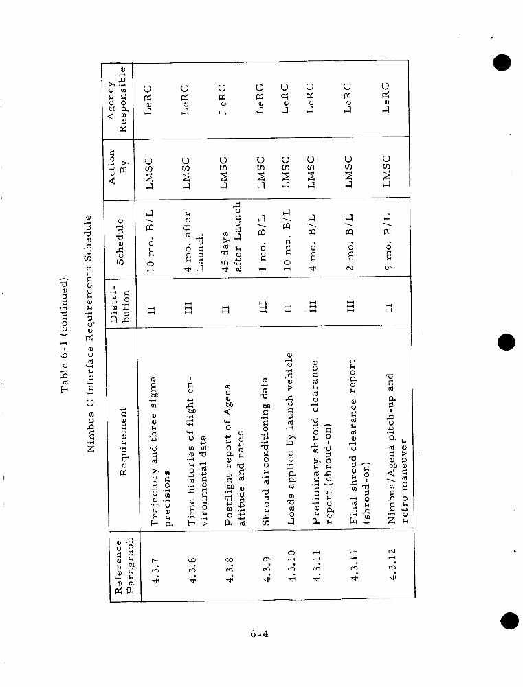
a,
73 a a,
VI
4
%
5 E
m c,
a, k
73 6
.I+
2 a, u rd k a, c,
H
W
d
u ? P m
E .rl z
a,
? a a,
VI
4
’do
42
5 E a, k .rl
2
u u u u u d d d d ec;
u pc;
a,
u d I4 J J s : : J a, a, a,
u d I4 a,
u u VI VI
J
u u u u u
J I 4 J J 2 2 $ 2 2 J
VI VI u VI
J 2 J
2 2
J E9 \
0 E 0 4
J 1
a
; 0 d
J E9 \
0 E W
J E9
d E
\
N
J 1
a
E 0
o\
H H
H H H
H H H H H H H H
H H
H H H
H H
rd
M v)
a, a, k
E .rl
.6,
9 -73
rd rd a M c
c,
.rl
.rl c,
2 5 V k
Id a .rl
2
a,
V 4
; > 5 d 9 rd
h P a a,
a a Id
a Id 0
4
.rl ”
0
J
d N
m m d
o . + r4 co r- co
m m m m m m 4 4 4 4 4 4 4 4
a
6 -4

e,
3 a a,
tn
A
5 m
$ E P
.d z
a,
b .rl u m
z
74
d 0 *rl b s a 4
a,
3 a e,
tn
l-l
5
I
'k" g 6.2 c, m ' T :
u u cr d : tn U
u tn
0 4 w 2
H H
H H
Ln In M M
L n Ln
..I
a, 4
2 z a 0 k a a, k 4 .. m e, a 0 U
* u cr VI U
.rl
... m e,
a 0 U
* u
2 u
.d
3 \
I
H
d 0
3 .d c,
2
5 k c, m
m a, .rl e u N
w U u cr \
8 .- m a, a 0 V
N
.rl
0 J U u cr \
8 ... m e,
a 0 V
a
.rl
u 6( tn * I
H H
u 'r.I
G ... a, 4
2 U 9
W 0 k a a, k 4 .. m a,
a 0 V
N
.,-I
u cr tn U ... a, 4
2 s 5 a 0 k
k 4
m a,
a 0 o m
a,
.rl
.d
w e c 3 v 'N u cro tn4 0 0
I
H H H
$ d 3 cd
a e,
3 W e,
4
r-l
.du m a, k 0 w a, a I1
4 a \
>L
6 - 5
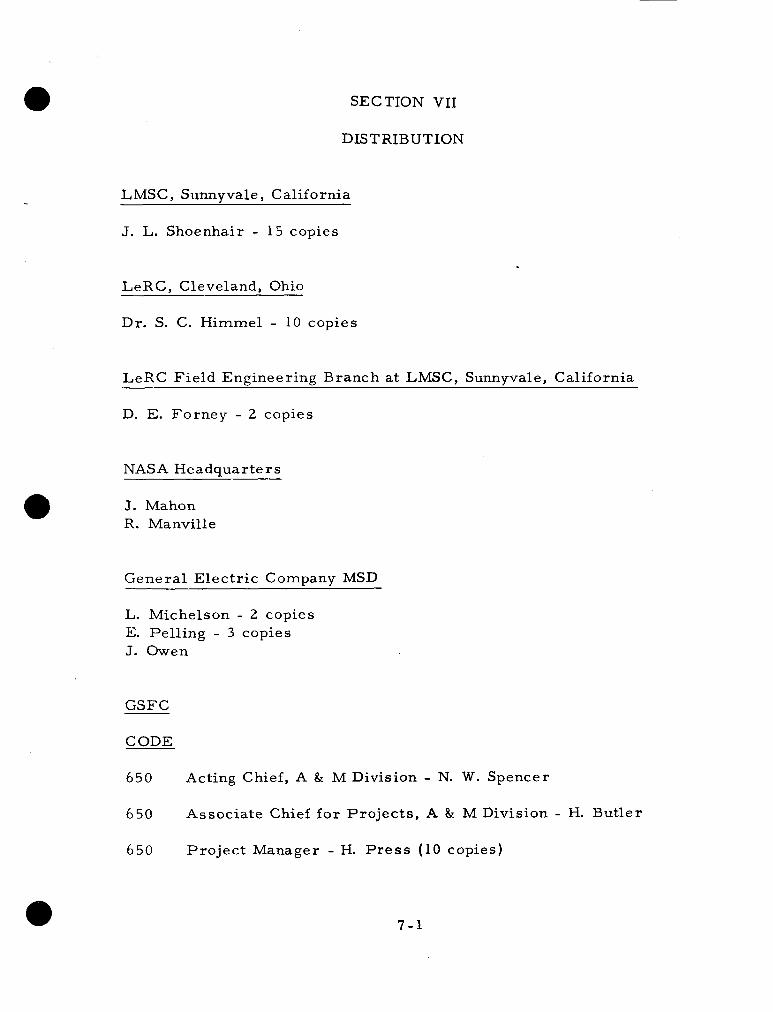
SECTION VI1
DISTRIBUTION
LMSC, Sunnyvale, California
J. L. Shoenhair - 15 copies
LeRC, Cleveland, Ohio
Dr. S . C. Himmel - 10 copies
LeRC Field Engineering Branch at LMSC, Sunnyvale, California
D. E. Forney - 2 copies
NASA Headquarters
J. Mahon R. Manville
General Electr ic Company MSD
L. Michelson - 2 copies E. Pelling - 3 copies J. Owen
GSFC
CODE
650 Acting Chief, A & M Division - N. W. Spencer
650 Associate Chief f o r Projects , A & M Division - H. Butler
650 Pro jec t Manager - H. Press (10 copies)
7 - 1

GSFC (Continued)
CODE
650
6 50
650
6 50
620
62 3
623
62 3
62 3
623
651
6 52
6 52
653
653
653
6 53
Deputy Pro jec t Manager - W. B. Huston (5 copies)
P ro jec t Coordinator - A. Fihelly
Nimbus P ro jec t Office - G. Delio
Nimbus Pro jec t Office - H. Nichols
Spacecraft Systems and P ro jec t s Division - D. G. Mazur
Head, Spacecraft Systems Branch - M. L. Moseson
Agena Coordinator - E. A. Rothenberg (2 copies)
Head, Agena Per formance Panel - R. E. Russey
Structural Systems Representat ive - G. D. Hinshelwood
Nimbus Vehicle Representative - J. H. W a l l s
Acting Head, Physics Branch - Dr. W. Nordberg
Head, Instrumentation Branch - J. Sargent
Instrumentation Branch - W. West
Head, Systems Engineering Branch - M. Schneebaum
Spacecraft Manager - S. Weiland
Integration and Tes t Technical Officer - R. Shapiro
Systems Engine e ring Branch GSFC / G E Representative Spacecraft Systems Engine e r - S . Kant Systems Tes t Controller Control System Technical Officer - G. Burdett Senior Electr ical Engineer Assis tant Spacecraft Manager
- J. L e a r y (5 copies)
- R. Devlin
- J. Strong - P. Crossf ie ld
7 -2

GSFC (Continued)
CODE
653
503
263
263
213
2 4 7
247
2 56
2 52
624
624
62 4
Systems Engineering Branch Senior Mechanical Engineer Nimbus Launch Operations Coordinator - R. Drummond
- E. Stengard
Tracking and Data Acquisition Sys tems Manager - D. Fahnestock
P ro jec t s Business Manager - D. F r i edman
PERT Analyst - B. Kwoka
Financial Management Analyst - E. Baden
Space Applications Negotiation Branch Section A Head - E. Roset te
Nimbus Integration Negotiator - J. Dammeyer
Documentation Branch
GSFC L ib ra ry - 3 copies
Manager, Goddard Launch Operations - R. H. Gray
Associate Manager, Goddard Launch Operations (WTR)
(5 copies) - J. B. Schwartz
Goddard Launch Operations Branch - W. Branch
7 - 3