laughton, february 2004draft - basis of estimate for review 1 theta 13 midwest site basis of...
TRANSCRIPT
Draft - Basis of Estimate for Review
1
Laughton, February 2004
Theta 13 Midwest SiteBasis of Estimate
for Underground ConstructionInput based on Preliminary Studies
Draft - Basis of Estimate for Review
2
Laughton, February 2004
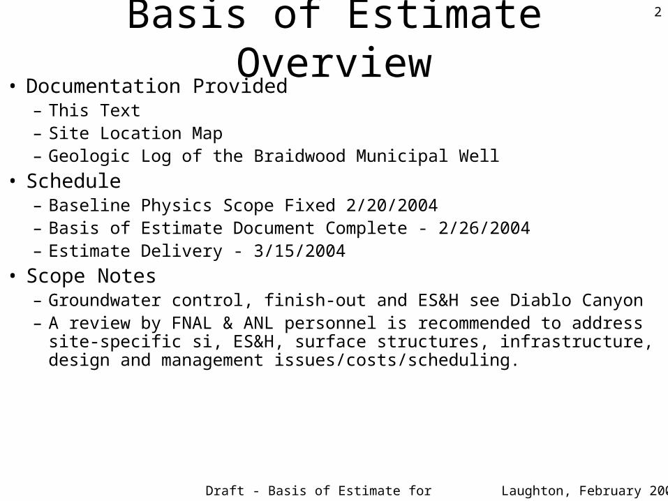
Basis of Estimate Overview• Documentation Provided
– This Text– Site Location Map– Geologic Log of the Braidwood Municipal Well
• Schedule– Baseline Physics Scope Fixed 2/20/2004– Basis of Estimate Document Complete - 2/26/2004– Estimate Delivery - 3/15/2004
• Scope Notes– Groundwater control, finish-out and ES&H see Diablo Canyon– A review by FNAL & ANL personnel is recommended to address site-specific si,
ES&H, surface structures, infrastructure, design and management issues/costs/scheduling.
Draft - Basis of Estimate for Review
3
Laughton, February 2004
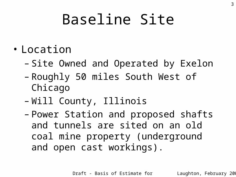
Baseline Site
• Location– Site Owned and Operated by Exelon– Roughly 50 miles South West of Chicago– Will County, Illinois– Power Station and proposed shafts and tunnels are
sited on an old coal mine property (underground and open cast workings).
Draft - Basis of Estimate for Review
4
Laughton, February 2004
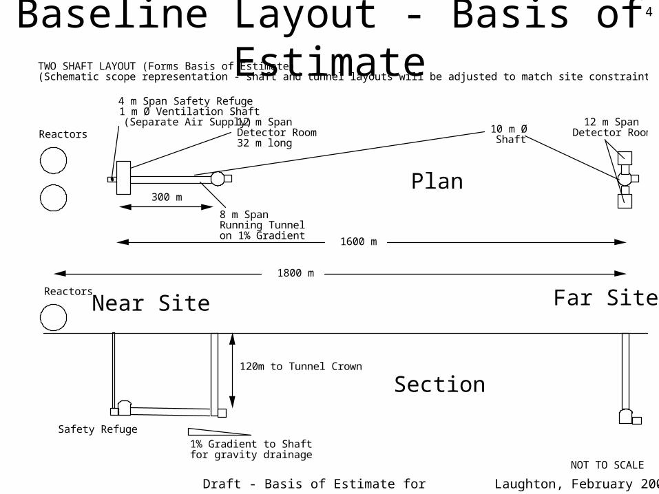
Baseline Layout - Basis of Estimate
Reactors
300 m
1600 m
1800 m
TWO SHAFT LAYOUT (Forms Basis of Estimate) (Schematic scope representation - shaft and tunnel layouts will be adjusted to match site constraints)
10 m Ø Shaft
12 m Span Detector Rooms
8 m Span Running Tunnel on 1% Gradient
4 m Span Safety Refuge 1 m Ø Ventilation Shaft (Separate Air Supply) 12 m Span
Detector Room 32 m long
1% Gradient to Shaft for gravity drainage
Reactors
Safety Refuge
NOT TO SCALE
120m to Tunnel Crown
Near Site Far Site
Plan
Section
Draft - Basis of Estimate for Review
5
Laughton, February 2004
Baseline & Option Commentary• The Scope of the Underground Works has not been
finalized and may be adjusted as new data is reported from other experiments.
• The Collaboration is considering options that would change the number and lengths of shafts, tunnels and chambers. One such option is shown on page 8.
• Where possible please provide bid items and unit pricing that will allow the approximate cost differentials of such changes to be calculated.
Draft - Basis of Estimate for Review
6
Laughton, February 2004
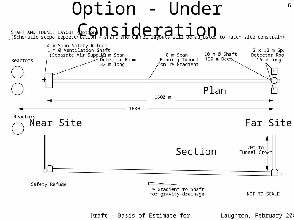
Option - Under Consideration
Reactors
1600 m
1800 m
4 m Span Safety Refuge 1 m Ø Ventilation Shaft (Separate Air Supply) 8 m Span
Running Tunnel on 1% Gradient
10 m Ø Shaft 120 m Deep
2 x 12 m Span Detector Rooms
16 m long
SHAFT AND TUNNEL LAYOUT (Option) (Schematic scope representation - shaft and tunnel layouts will be adjusted to match site constraints).
12 m Span Detector Room 32 m long
1% Gradient to Shaft for gravity drainage
Reactors
Safety Refuge
NOT TO SCALE
120m to Tunnel Crown
Near Site Far Site
Plan
Section
Draft - Basis of Estimate for Review
7
Laughton, February 2004
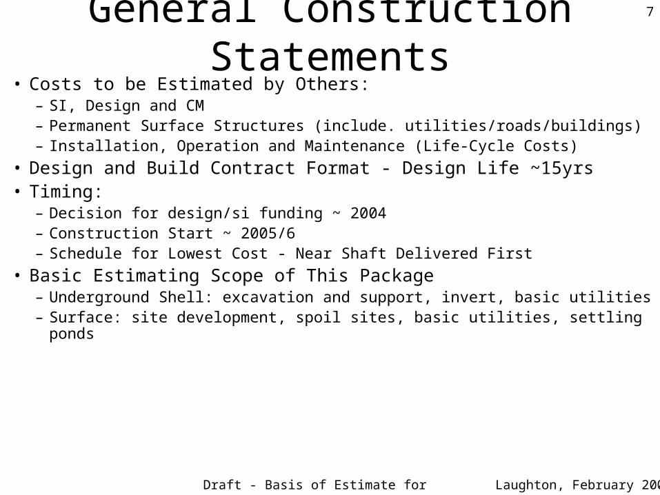
General Construction Statements• Costs to be Estimated by Others:
– SI, Design and CM– Permanent Surface Structures (include. utilities/roads/buildings)– Installation, Operation and Maintenance (Life-Cycle Costs)
• Design and Build Contract Format - Design Life ~15yrs• Timing:
– Decision for design/si funding ~ 2004– Construction Start ~ 2005/6– Schedule for Lowest Cost - Near Shaft Delivered First
• Basic Estimating Scope of This Package– Underground Shell: excavation and support, invert, basic utilities– Surface: site development, spoil sites, basic utilities, settling ponds
Draft - Basis of Estimate for Review
8
Laughton, February 2004
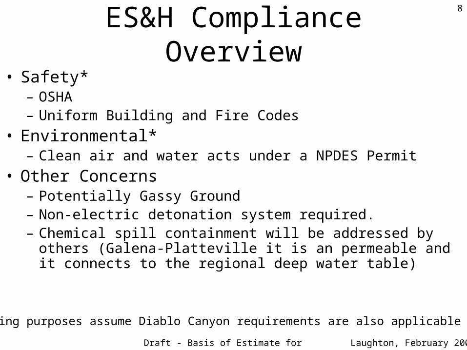
ES&H Compliance Overview• Safety*
– OSHA– Uniform Building and Fire Codes
• Environmental*– Clean air and water acts under a NPDES Permit
• Other Concerns– Potentially Gassy Ground– Non-electric detonation system required.– Chemical spill containment will be addressed by others (Galena-
Platteville it is an permeable and it connects to the regional deep water table)
(*For estimating purposes assume Diablo Canyon requirements are also applicable at Braidwood)
Draft - Basis of Estimate for Review
9
Laughton, February 2004
Security Issues• Location
– Near and Far sites are both on Exelon Property.
• Site Access Issues– At the near shaft site access will be from within an heavily-trafficked
area close to the reactor - assume 15 minutes inefficiency/shift to get through the check-points.
– At the far shaft site independent access is possible - assume no delay.
• Construction Site Security– Assume guards at both sites 24hr/day, 7 days/week. – Both sites to be fenced and gated.– Additional fencing for magazines (far and near) - probably located
adjacent to spoil areas within view of guards.
Draft - Basis of Estimate for Review
10
Laughton, February 2004
Site Utilities
• Specific shaft locations have not been identified. Assumptions for costing purposes are as follows:
• Utilities– Anticipate ability to tie in to local lines.– Say 300 m of pipeline/cable/wire at each site.– Assume all conventional connections required, including
power, water, sewer, telephone and other necessary services...
• Power Supply– Anticipate supplying transformers.– Anticipate paying for all connections and for some assistance
from Exelon on siting and installation of all utility runs across their site.
Draft - Basis of Estimate for Review
11
Laughton, February 2004
Surface Scope Assumptions • Near & Far Shaft Sites
– Paved road to within ~ 100 m of both shaft platforms.– Sites are in relatively open, flat, low-lying brush-covered areas - assume topsoil
stripping, geotextile and at least 60 cm of hard core needed over each area.
• Near & Far Shaft Spoil Sites– Should be able to find sites adjacent to the platforms - assume 200 m haulage (assume
the dolostone tunnel rock will be stockpiled for reuse). – The non-dolostone spoil piles will need capping.
• Near & Far Shaft Water Treatment, Settlement & Discharge Systems– Assume 50 gpm maximum groundwater inflow/shaft - handled at each outfall.
• Near & Far Shaft End of Construction – Permanent pumping systems, settling ponds and outfall to Waters of the State (not
identified - assume 500 m to outfall)– Repair any wear and tear to Exelon and Braidwood infrastructure/utilities/roads
• Near & Far Shaft Decommissioning and Site Rehabilitation– Shaft installations removed, and 30 m C-I-P concrete plug (~5m into bedrock). On
surface, hard core removed, topsoil replaced and landscaped.
Draft - Basis of Estimate for Review
12
Laughton, February 2004
Shaft Blast Mitigation• Potential Blasting Problems to Address at Both Shaft Sites
– Potential shaft sites likely to be within a few 100 m of Residents/Power Plant
– Potential shaft sites likely to be in close proximity to overhead power lines
• Suggested Mitigation Measures to Include in Estimate– Heavy blast mats to contain 100% of flyrock
– Limit blast hours in shaft and first ~ 100 m of tunnel - say 6 am until 10 pm
– Noise “mufflers” (Don: in Portland Frontier Kemper (Tri-Met) used a “blast door” at the portal - if it works we could remove blast hour restrictions?)
– Monitoring of vibration and noise - say 3 instruments
• Water Monitoring– Ensure Project does not draw-down the water table or impact the surrounding
environment - place piezometers in all site investigation boreholes (estimated by others).
Draft - Basis of Estimate for Review
13
Laughton, February 2004
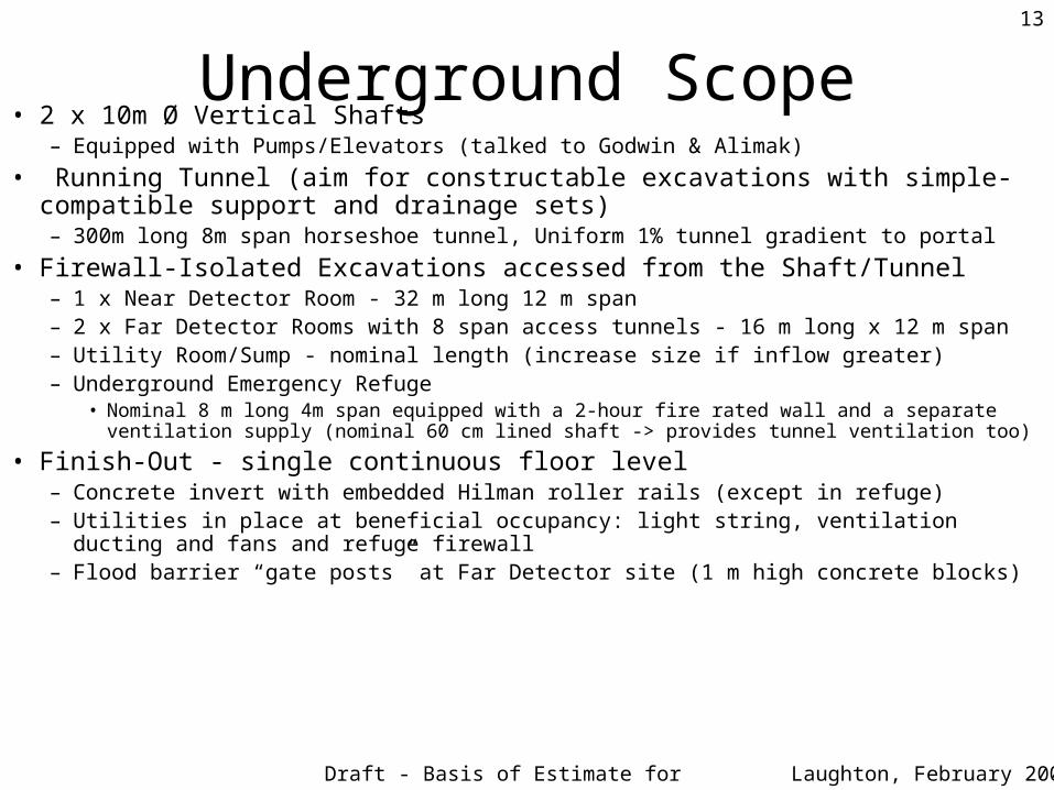
Underground Scope• 2 x 10m Ø Vertical Shafts
– Equipped with Pumps/Elevators (talked to Godwin & Alimak)
• Running Tunnel (aim for constructable excavations with simple-compatible support and drainage sets)– 300m long 8m span horseshoe tunnel, Uniform 1% tunnel gradient to portal
• Firewall-Isolated Excavations accessed from the Shaft/Tunnel– 1 x Near Detector Room - 32 m long 12 m span – 2 x Far Detector Rooms with 8 span access tunnels - 16 m long x 12 m span– Utility Room/Sump - nominal length (increase size if inflow greater)– Underground Emergency Refuge
• Nominal 8 m long 4m span equipped with a 2-hour fire rated wall and a separate ventilation supply (nominal 60 cm lined shaft -> provides tunnel ventilation too)
• Finish-Out - single continuous floor level– Concrete invert with embedded Hilman roller rails (except in refuge)– Utilities in place at beneficial occupancy: light string, ventilation ducting and fans and refuge
firewall– Flood barrier “gate posts” at Far Detector site (1 m high concrete blocks)
Draft - Basis of Estimate for Review
14
Laughton, February 2004
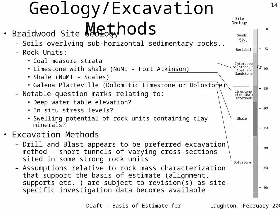
Geology/Excavation Methods• Braidwood Site Geology
– Soils overlying sub-horizontal sedimentary rocks..– Rock Units:
• Coal measure strata• Limestone with shale (NuMI - Fort Atkinson)• Shale (NuMI - Scales)• Galena Platteville (Dolomitic Limestone or Dolostone)
– Notable question marks relating to:• Deep water table elevation?• In situ stress levels?• Swelling potential of rock units containing clay minerals?
• Excavation Methods– Drill and Blast appears to be preferred excavation method - short
tunnels of varying cross-sections sited in some strong rock units– Assumptions relative to rock mass characterization that support
the basis of estimate (alignment, supports etc. ) are subject to revision(s) as site-specific investigation data becomes available
Sands and
Tills
0
50
150
100
200
250
300
350
400
Interbedded Silstone, Shale
Coal and Sandstones
Limestone with Shale Interbeds
Shale
Dolostone
Residual
Site Geology
Draft - Basis of Estimate for Review
15
Laughton, February 2004
Preliminary Estimate of Underground Construction Scope
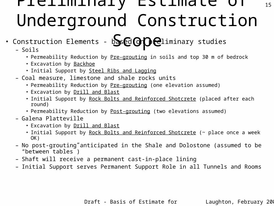
• Construction Elements - based on preliminary studies– Soils
• Permeability Reduction by Pre-grouting in soils and top 30 m of bedrock• Excavation by Backhoe• Initial Support by Steel Ribs and Lagging
– Coal measure, limestone and shale rocks units • Permeability Reduction by Pre-grouting (one elevation assumed)• Excavation by Drill and Blast• Initial Support by Rock Bolts and Reinforced Shotcrete (placed after each round)• Permeability Reduction by Post-grouting (two elevations assumed)
– Galena Platteville • Excavation by Drill and Blast• Initial Support by Rock Bolts and Reinforced Shotcrete (~ place once a week OK)
– No post-grouting anticipated in the Shale and Dolostone (assumed to be “between tables”)– Shaft will receive a permanent cast-in-place lining – Initial Support serves Permanent Support Role in all Tunnels and Rooms
Draft - Basis of Estimate for Review
16
Laughton, February 2004
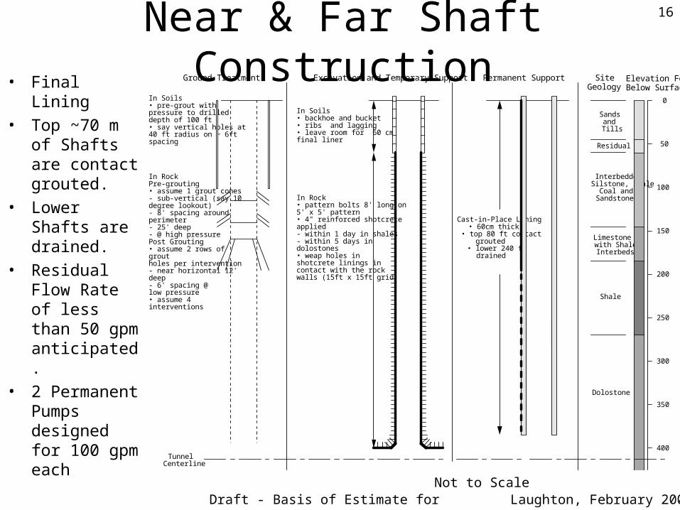
Near & Far Shaft Construction• Final Lining
• Top ~70 m of Shafts are contact grouted.
• Lower Shafts are drained.
• Residual Flow Rate of less than 50 gpm anticipated.
• 2 Permanent Pumps designed for 100 gpm each
Elevation Feet Below Surface
In Soils • backhoe and bucket • ribs and lagging • leave room for 60 cm final liner
Cast-in-Place Lining • 60cm thick
• top 80 ft contact grouted
• lower 240 ft drained
In Rock • pattern bolts 8' long on 5' x 5' pattern • 4" reinforced shotcrete applied - within 1 day in shales - within 5 days in dolostones • weap holes in shotcrete linings in contact with the rock walls (15ft x 15ft grid)
In Soils • pre-grout with pressure to drilled depth of 100 ft • say vertical holes at 40 ft radius on ~ 6ft spacing
In Rock Pre-grouting • assume 1 grout cones - sub-vertical (say 10 degree lookout) - 8' spacing around perimeter - 25' deep - @ high pressure Post Grouting • assume 2 rows of grout holes per intervention - near horizontal 12' deep - 6' spacing @ low pressure • assume 4 interventions
Tunnel Centerline
Sands and Tills
0
50
150
100
200
250
300
350
400
Interbedded Silstone, Shale
Coal and Sandstones
Limestone with Shale Interbeds
Shale
Dolostone
Residual
Permanent Support Site Geology
Excavation and Temporary SupportGround Treatment
Not to Scale
Draft - Basis of Estimate for Review
17
Laughton, February 2004
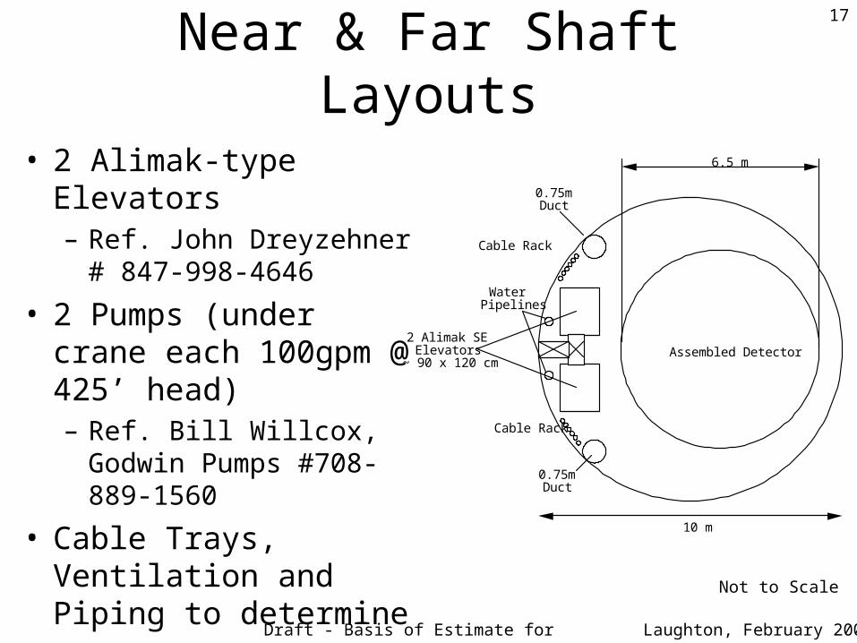
Near & Far Shaft Layouts
• 2 Alimak-type Elevators– Ref. John Dreyzehner #
847-998-4646
• 2 Pumps (under crane each 100gpm @ 425’ head)– Ref. Bill Willcox, Godwin
Pumps #708-889-1560
• Cable Trays, Ventilation and Piping to determine
Not to Scale
10 m
6.5 m
0.75m Duct
0.75m Duct
2 Alimak SE Elevators
~ 90 x 120 cmAssembled Detector
Cable Rack
Cable Rack
Water Pipelines
Draft - Basis of Estimate for Review
18
Laughton, February 2004
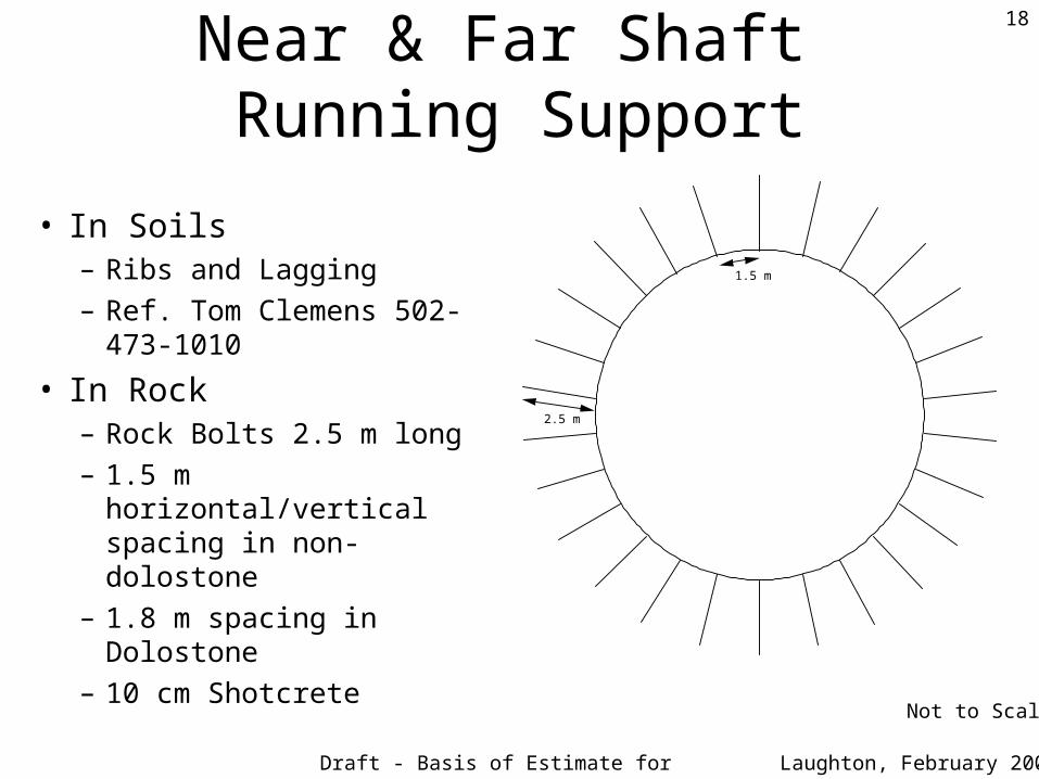
Near & Far Shaft Running Support
• In Soils– Ribs and Lagging– Ref. Tom Clemens 502-
473-1010
• In Rock– Rock Bolts 2.5 m long– 1.5 m horizontal/vertical
spacing in non-dolostone– 1.8 m spacing in Dolostone– 10 cm Shotcrete
Not to Scale
2.5 m
1.5 m
Draft - Basis of Estimate for Review
19
Laughton, February 2004
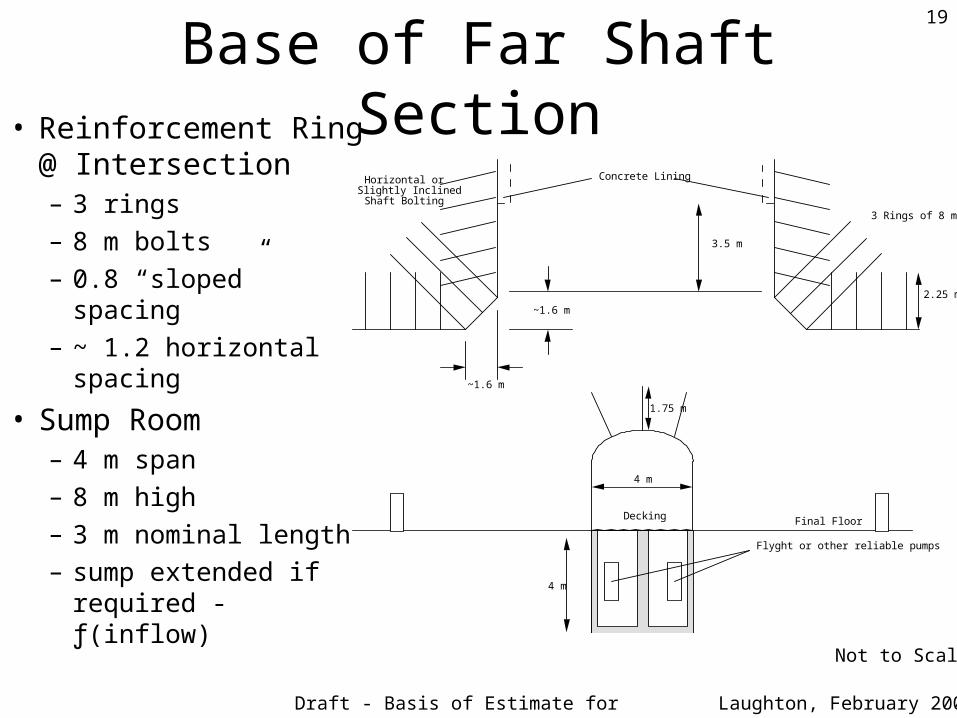
Base of Far Shaft Section• Reinforcement Ring
@ Intersection– 3 rings– 8 m bolts– 0.8 “sloped” spacing– ~ 1.2 horizontal
spacing
• Sump Room– 4 m span– 8 m high– 3 m nominal length– sump extended if
required - ƒ(inflow) Not to Scale
Final Floor
4 m
Flyght or other reliable pumps
Decking
Concrete LiningHorizontal or Slightly Inclined
Shaft Bolting
3.5 m
~1.6 m
~1.6 m
1.75 m
4 m
3 Rings of 8 m bolts
2.25 m
Draft - Basis of Estimate for Review
20
Laughton, February 2004
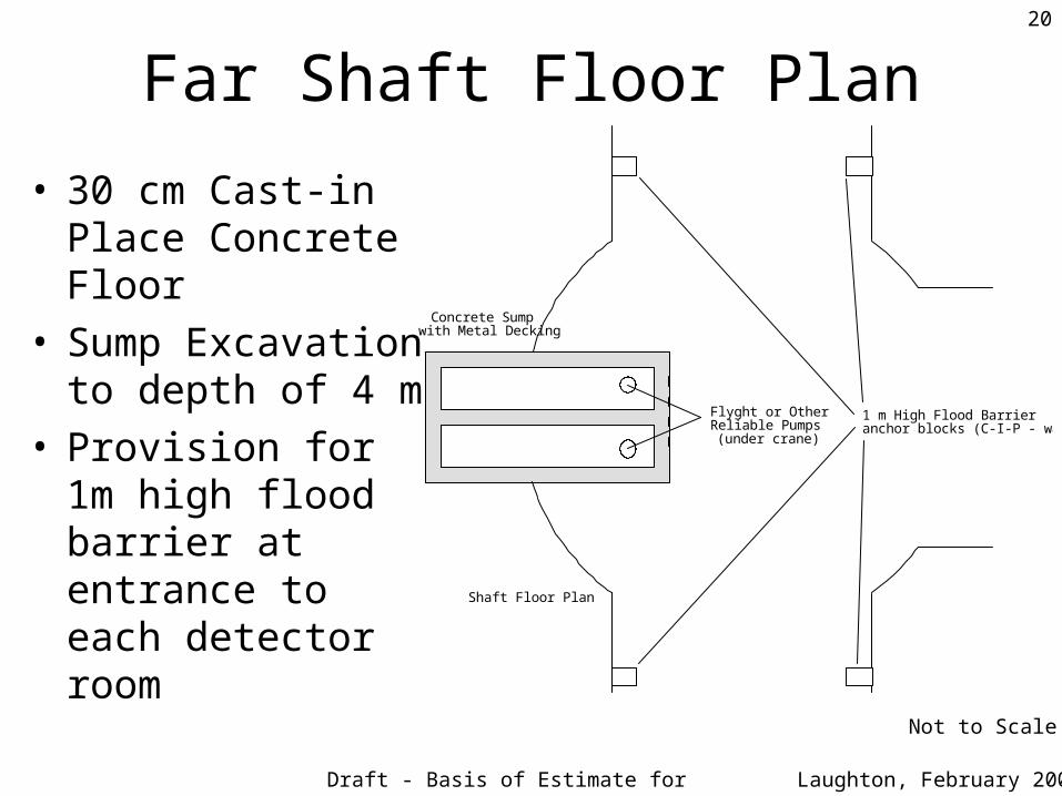
Far Shaft Floor Plan
• 30 cm Cast-in Place Concrete Floor
• Sump Excavation to depth of 4 m
• Provision for 1m high flood barrier at entrance to each detector room
Not to Scale
Concrete Sump with Metal Decking
Shaft Floor Plan
Flyght or Other Reliable Pumps
(under crane)
1 m High Flood Barrier anchor blocks (C-I-P - wall bolted)
Draft - Basis of Estimate for Review
21
Laughton, February 2004
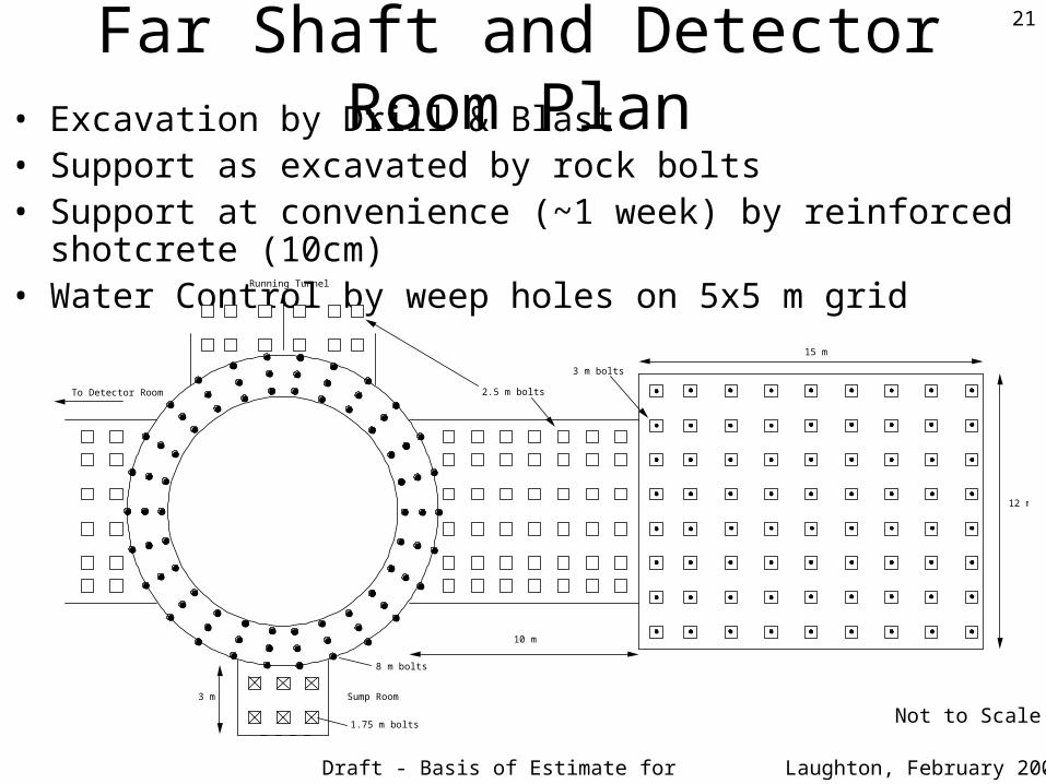
Far Shaft and Detector Room Plan• Excavation by Drill & Blast• Support as excavated by rock bolts• Support at convenience (~1 week) by reinforced shotcrete (10cm)• Water Control by weep holes on 5x5 m grid
Not to Scale
To Detector Room
Running Tunnel
10 m
Sump Room 3 m
1.75 m bolts
8 m bolts
15 m
12 m
3 m bolts
2.5 m bolts
Draft - Basis of Estimate for Review
22
Laughton, February 2004
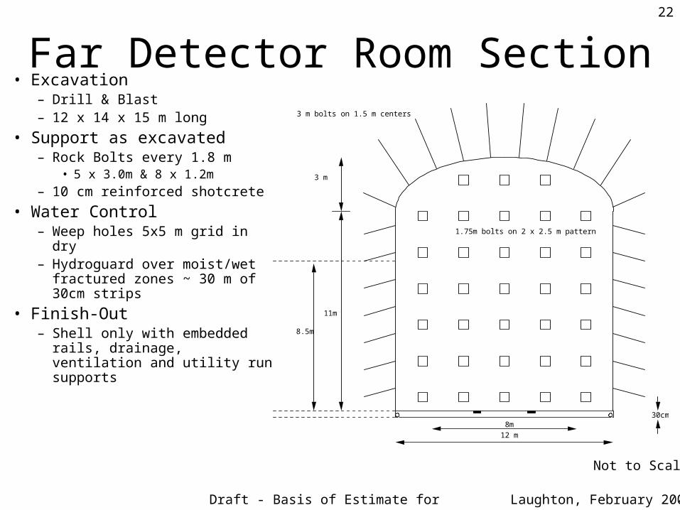
Far Detector Room Section• Excavation
– Drill & Blast– 12 x 14 x 15 m long
• Support as excavated– Rock Bolts every 1.8 m
• 5 x 3.0m & 8 x 1.2m
– 10 cm reinforced shotcrete
• Water Control– Weep holes 5x5 m grid in dry– Hydroguard over moist/wet
fractured zones ~ 30 m of 30cm strips
• Finish-Out – Shell only with embedded rails,
drainage, ventilation and utility run supports
Not to Scale
8.5m
8m30cm
3 m
11m
3 m bolts on 1.5 m centers
1.75m bolts on 2 x 2.5 m pattern
12 m
Draft - Basis of Estimate for Review
23
Laughton, February 2004
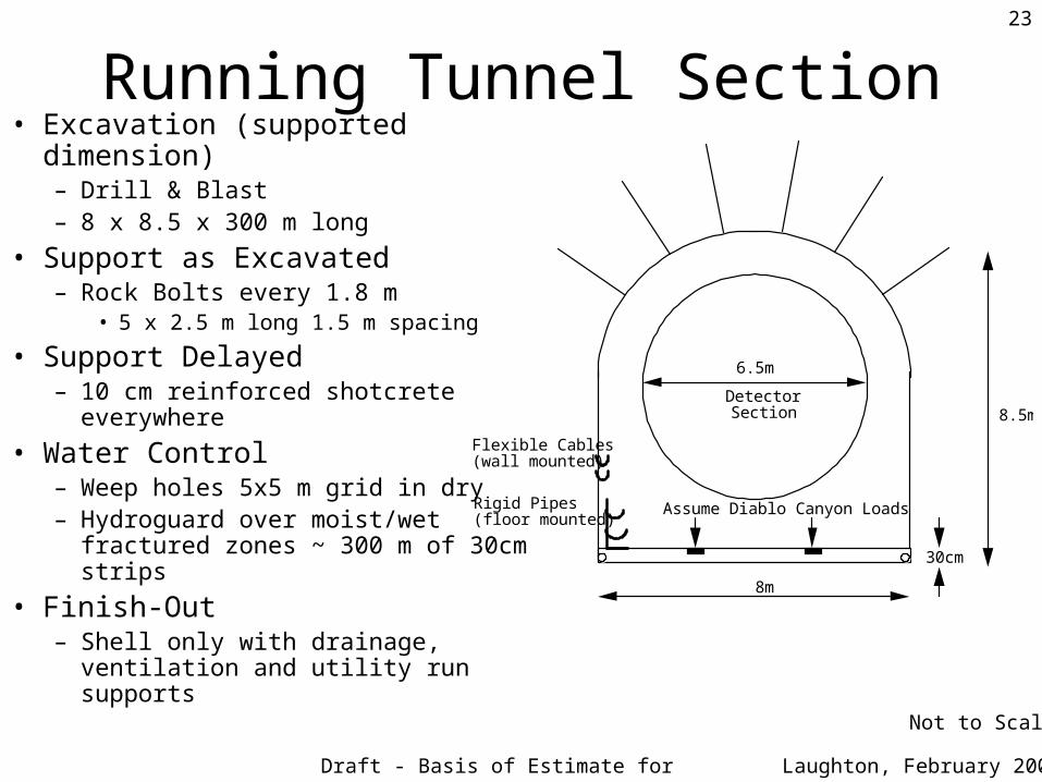
Running Tunnel Section• Excavation (supported dimension)
– Drill & Blast– 8 x 8.5 x 300 m long
• Support as Excavated– Rock Bolts every 1.8 m
• 5 x 2.5 m long 1.5 m spacing
• Support Delayed– 10 cm reinforced shotcrete
everywhere
• Water Control– Weep holes 5x5 m grid in dry– Hydroguard over moist/wet fractured
zones ~ 300 m of 30cm strips
• Finish-Out – Shell only with drainage, ventilation
and utility run supports Not to Scale
6.5m
8m
30cm
8.5m
Flexible Cables (wall mounted)
Rigid Pipes (floor mounted)
Detector Section
Assume Diablo Canyon Loads
Draft - Basis of Estimate for Review
24
Laughton, February 2004
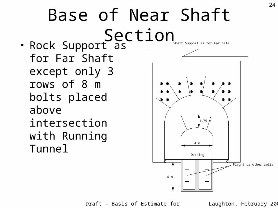
Base of Near Shaft Section• Rock Support as for Far
Shaft except only 3 rows of 8 m bolts placed above intersection with Running Tunnel
4 m
Flyght or other reliable pumps
Decking
1.75 m
4 m
Shaft Support as for Far Site
Draft - Basis of Estimate for Review
25
Laughton, February 2004
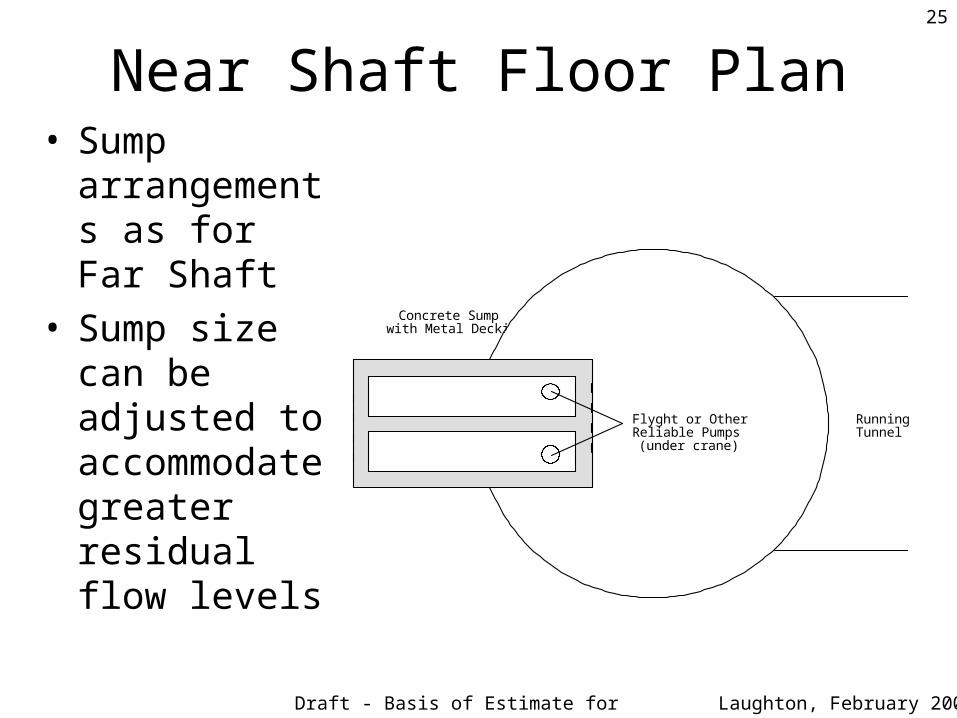
Near Shaft Floor Plan• Sump
arrangements as for Far Shaft
• Sump size can be adjusted to accommodate greater residual flow levels
Concrete Sump with Metal Decking
Flyght or Other Reliable Pumps (under crane)
Running Tunnel
Draft - Basis of Estimate for Review
26
Laughton, February 2004
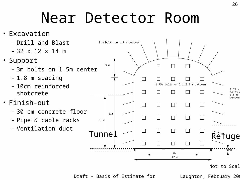
Near Detector Room• Excavation
– Drill and Blast– 32 x 12 x 14 m
• Support– 3m bolts on 1.5m center– 1.8 m spacing– 10cm reinforced shotcrete
• Finish-out– 30 cm concrete floor – Pipe & cable racks– Ventilation duct
8.5m
8m30cm
3 m
11m
3 m bolts on 1.5 m centers
1.75 m bolts on 1.5 m centers
1.75m bolts on 2 x 2.5 m pattern
12 m
Tunnel Refuge
Not to Scale
Draft - Basis of Estimate for Review
27
Laughton, February 2004
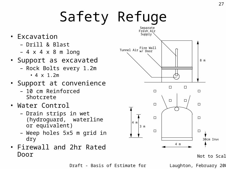
Safety Refuge• Excavation
– Drill & Blast– 4 x 4 x 8 m long
• Support as excavated– Rock Bolts every 1.2m
• 4 x 1.2m
• Support at convenience– 10 cm Reinforced Shotcrete
• Water Control– Drain strips in wet (hydroguard,
waterline or equivalent)– Weep holes 5x5 m grid in dry
• Firewall and 2hr Rated Door
Not to Scale
30cm Invert
4 m
4 m3 m
Separate Fresh Air
Supply
Tunnel AirFire Wall w/ Door
8 m
Draft - Basis of Estimate for Review
28
Laughton, February 2004
Underground Finish-Out• Plan for no encroachment on clearance space anywhere but especially in the
arch section of tunnel - plan the excavation profile accordingly (there is no problem if the excavated tunnel centerline “wiggles” a bit as long as the wiggle is gradual say ~ 10cm in 10m and to-portal drain slope is maintained by the pipes
• Water control measures as for Diablo Canyon (weep holes in lower half of shafts and tunnels and drain strips in detector rooms)
• A nominal overbreak limit should be called-out - say ~ 30cm• Continuous Concrete Invert
– Embedded invert drain pipes along the sidewalls– Pipe/Cable Stands, flexible cables may be added/hung from wall
• Ventilation - 60 cm duct currently sized– exhaust/inlets at crown of excavated structures (potentially gassy ground)– Maximum occupancy 25 person during installation– Fan left-in-place to have capacity to make 1 complete air change an hour (say
reconditioned construction fan OK)
Draft - Basis of Estimate for Review
29
Laughton, February 2004
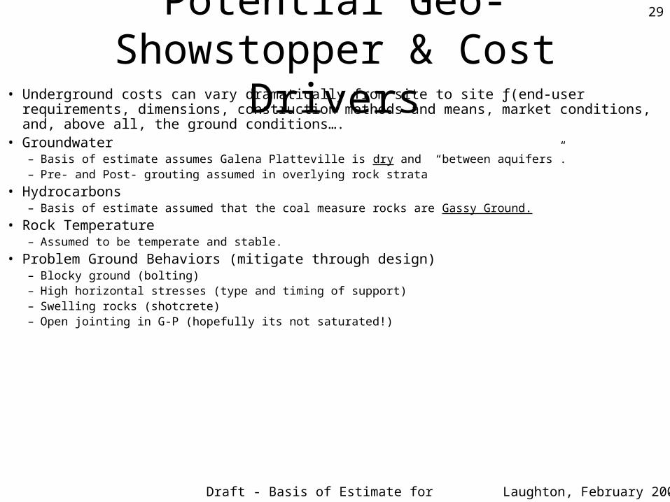
Potential Geo-Showstopper & Cost Drivers
• Underground costs can vary dramatically from site to site ƒ(end-user requirements, dimensions, construction methods and means, market conditions, and, above all, the ground conditions….
• Groundwater– Basis of estimate assumes Galena Platteville is dry and “between aquifers”.– Pre- and Post- grouting assumed in overlying rock strata
• Hydrocarbons– Basis of estimate assumed that the coal measure rocks are Gassy Ground.
• Rock Temperature– Assumed to be temperate and stable.
• Problem Ground Behaviors (mitigate through design)– Blocky ground (bolting)– High horizontal stresses (type and timing of support)– Swelling rocks (shotcrete)– Open jointing in G-P (hopefully its not saturated!)
Draft - Basis of Estimate for Review
30
Laughton, February 2004
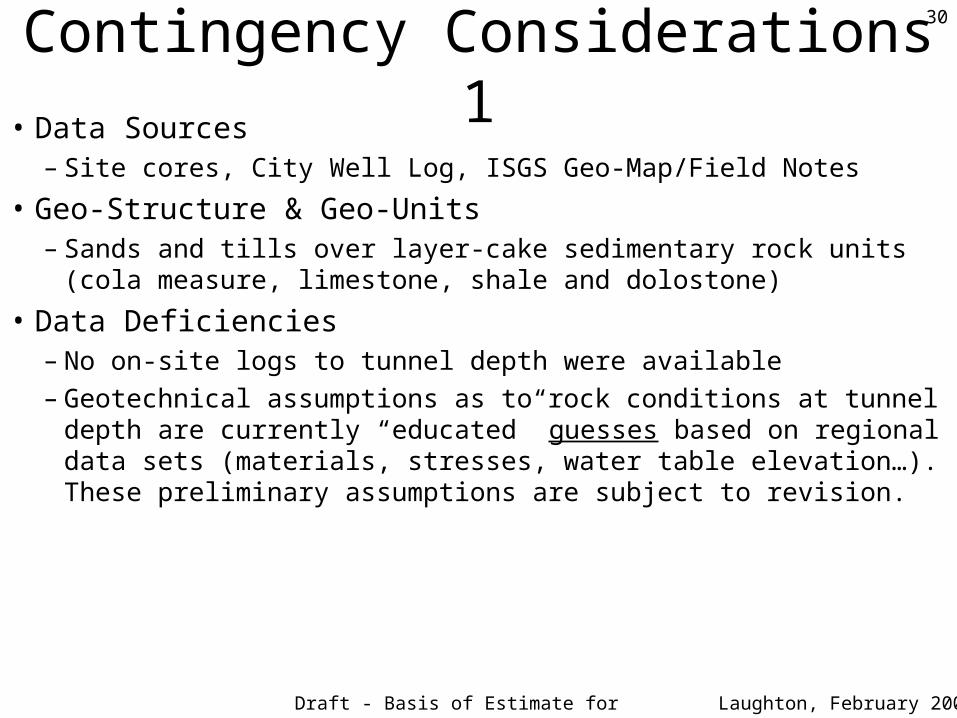
Contingency Considerations 1• Data Sources
– Site cores, City Well Log, ISGS Geo-Map/Field Notes
• Geo-Structure & Geo-Units– Sands and tills over layer-cake sedimentary rock units (cola measure,
limestone, shale and dolostone)
• Data Deficiencies– No on-site logs to tunnel depth were available– Geotechnical assumptions as to rock conditions at tunnel depth are currently
“educated” guesses based on regional data sets (materials, stresses, water table elevation…). These preliminary assumptions are subject to revision.
Draft - Basis of Estimate for Review
31
Laughton, February 2004
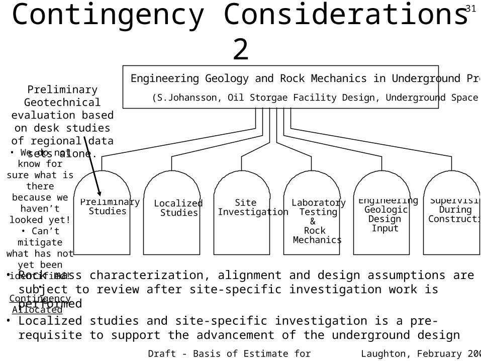
Contingency Considerations 2
• Rock mass characterization, alignment and design assumptions are subject to review after site-specific investigation work is performed
• Localized studies and site-specific investigation is a pre-requisite to support the advancement of the underground design
Preliminary Studies
Localized Studies
Site Investigation
Laboratory Testing
& Rock
Mechanics
Engineering Geologic Design Input
Supervision During
Construction
Engineering Geology and Rock Mechanics in Underground Projects
(S.Johansson, Oil Storgae Facility Design, Underground Space, 1980)Preliminary
Geotechnical evaluation based on desk studies of regional data sets alone.
• We do not know for sure what is
there because we haven’t looked
yet!• Can’t mitigate what has not yet been identified!• Contingency
Allocated