laser scan micrometer - kerley corporation
TRANSCRIPT

Sensor Systems
Aurora, Illinois(Corporate Headquarters)(630) 978-5385Westford, Massachusetts(978) 692-8765Huntersville, North Carolina(704) 875-8332Mason, Ohio(513) 754-0709Plymouth, Michigan(734) 459-2810City of Industry, California(626) 961-9661Kirkland, Washington(408) 396-4428
LASER SCAN MICROMETER
Bulletin No. 1859-544
High speed scanning (3200 scans/sec) and high accuracy, non-contact measuring system
FEATURES
A variety of models seamlessly cover measurement ranges from .0002" (0.005mm) to 6.3" (160mm)With a wide variety of models, LSM measurement can be utilized in diverse applications. The LSM-500S can measure ultra-fine wires as thin as .0002" (0.005mm) in diameter to a resolution of .000001" (0.00001mm), and the LSM-516S can measure cylindrical workpieces with a diameter as large as 6.3" (160mm). The LSM-9506 is a bench-top type model which has an integrated display section and measurement section, all in one unit.
Ultra-high speed 3200 scans/secThe incorporation of a sixteen-face polygon mirror and a high-precision motor now makes high speed scanning of 3200 scans per second possible. This capability is ideal, for example, to take measurements on a production line that moves at high speed or to take measurements of workpieces that vibrate.
Certified accuracy over the entire measurement rangeThe specified high accuracy over the entire measurement range is certified by the "Traceability System to the International Standard", which Mitutoyo has established as a leading manufacturer of precision measurement tools and instruments. Laser safety precaution
Mitutoyo Laser Scan Micrometers use a low-power visible laser for measurement. The laser is a CLASS 2 IEC 825-1 device and a CLASS II 21 CDRH device. Warning and explanation labels, as shown right, are attached to the Laser Scan Micrometers as is appropriate.
Laser Scan Micrometers:High speed scanning (3200 scans/sec) and high accuracy, non-contact measuring systems. The LSM features a very high scanning speed which enables inspection of small, high temperature or fragile workpieces even if they are in motion or vibrating.
Improved resistance to IP64-level environmentsThe measuring unit has been extensively improved to resist severe measurement environments. As a result, for example, it can also operate in a 113°F (45°C) environment. (IP64-level resistance is not guaranteed for the display unit and the LSM-9506.)
DIN-size compact panel-mounted display unit (LSM-5100, made-to-order model)The LSM-5100 display unit is assembled in a compact DIN size, allowing it to be mounted in a panel. It is suitably sized for incorporation into a rack, etc., for use in production lines.
Standard I/O output, analog output and RS-232C output interfacesThe LSM-5100/6200/6900 has a standard I/O and analog output interfaces to connect it with an operation controller or PLC used in a production line. Also, every model has a standard RS-232C interface for connection to personal computers or printers.
3
Diameter
Dia.
Out ofroundness
Reference edge
Reference edge
Referenceedge
Reference edge
Gap
In-line measurement of glass fiber or fine wire diameter
Measurement of form of parts
Measurement of outer diameter of optical connector and ferrule
Measurement of tape width
Measurement of gap between rollers
Measurement of laser disk and magnetic disk head movement
Measurement of film sheet thickness
Measurement of interval of IC chip leads
Measurement of unevenness of film and sheet
X- and Y-axis measurement of electric cables and fibers
Measurement of outer diameter and roundness of cylinder
Measurement of outer diameter of cylinder
Motor driver
Power source
ROMRAM
Polygonmirror
Collimator lens Condenser lens
Photoelectric element(receiver)
Amplifier
Workpiece
Photoelectric element(Reset signal generation)
Motor
Clock pulseMP RS
RS
Semiconductor laser
CPU
Edge detectioncircuit
Edge detectioncircuit
Segmentselection
circuitGateCounter
Expansionslot
Foot switchAnalog I/ORS-232CKeyboard
Data display
Motor driving pulse
PRINCIPLE
APPLICATIONS
A laser beam emitted from the oscillator is directed at the polygon mirror which rotates at a high speed and is synchronized by clock pulses. The direction of the beam reflected by the mirror is changed via the collimator lens and aims straight at the workpiece. As the polygon mirror rotates, the horizontal laser beam travels across the receiver and, if it is not obstructed by a workpiece, reaches the receiver. The output voltage of the photoelectric element varies proportionally with the amount of light which reaches the photoelectric cell. The timed pulses generated during the beam obstruction by the workpiece represent the dimension of the workpiece.

4
ALL MODELS OF LASER SCAN MICROMETER
MEASURING UNITSAppearance Model Laser
ClassificationMeasuringrange
Resolution(Selectable)
Refer to...
LSM-902* Visible (650nm),IEC Class 2/FDA Class II
.0002" - .08"(0.1 - 25mm)
.000001" - .0005"(0.01µm - 10µm)
Page 6
LSM-500S Visible (650nm),IEC Class 2/FDA Class II
.0002" - .08"(0.005 - 2mm)
.000001" - .0005"(0.01µm - 10µm)
Page 7
LSM-501S Visible (650nm),IEC Class 2/FDA Class II
.002" - .4"(0.05 - 10mm)FDA Class II
.000001" - .0005"(0.01µm - 10µm)
Page 8
LSM-503S Visible (650nm),IEC Class 2/FDA Class II
.012" - 1.18"(0.3 - 30mm)
.000001" - .005"(0.02µm - 100µm)
Page 9
LSM-506S Visible (650nm),IEC Class 2/FDA Class II
.04" - 2.36"(1 - 60mm)
.000002" - .005"(0.05µm - 100µm)
Page 10
LSM-512S Visible (650nm),IEC Class 2/FDA Class II
.04" - 4.72"(1 - 120mm)
.000005" - .005"(0.1µm - 100µm)
Page 11
LSM-516S Visible (650nm),IEC Class 2/FDA Class II
.04" - 6.30"(1 - 160mm)
.000005" - .005"(0.1µm - 100µm)
Page 12
With display unit
LSM-9506
Measuring unit - display unit one-piece structure for bench-top use
Visible (650nm),IEC Class 2/FDA Class II
.02" - 2.36"(0.5 - 60mm)
.000002" - .005"(0.05µm - 100µm)
Pages 13
DISPLAY UNITSAppearance Model Type Application Interface units
equippedRefer to...
LSM-6200LSM-6900*
Multi-function type Bench-top use • RS-232C• I/O• Analog output
Pages 14
LSM-5100**(made-to-order)
Compact type Assembly/bench-top use(DIN size)
• RS-232C• I/O• Analog output
Pages 15
*LSM-902 and LSM-6900 are factory-set packages. **When connecting with the LSM-500S series, the scanning speed becomes 1600 scans/sec.
5
02AGC840 02AGC940
Extension signal cable
Extension relay cable
OPTIONAL ACCESSORIESAppearance Order No. Description Application Refer
to...02AGD11002AGD12002AGD18002AGD13002AGD14002AGD15002AGM30002AGD170
Calibration gage setCalibration gage setCalibration gage setCalibration gage setCalibration gage setCalibration gage setCalibration gage setCalibration gage set
LSM-500SLSM-501SLSM-902LSM-503SLSM-506SLSM-512SLSM-516SLSM-9506
Page 22
02AGP150 Dual-type add-on unit LSM-6200 Page 22
02AGC84002AGC88002AGC91002AGC940
Digimatic (SPC) codeout unit2nd I/O & analog interface unitBCD interface unitGP-IB interface unit
LSM-6200/6900LSM-6200/6900LSM-6200/6900LSM-6200/6900
Pages20 & 21
02AGN780A02AGN780B02AGN780C02AGN780D
Extension signal cable 16' (5m)Extension signal cable 32' (10m)Extension signal cable 48' (15m)Extension signal cable 64' (20m)
Any model of LSM*Any model of LSM*Any model of LSM*Any model of LSM*
Page 23
02AGC150A02AGC150B02AGC150C
Extension relay cable 3' (1m)Extension relay cable 9' (3m)Extension relay cable 16' (5m)
Any model of LSM**Any model of LSM**Any model of LSM**
Page 23
936937 SPC cable 3' (1m) LSM-6200/9506 Page 23
937179T Footswitch LSM-6200/9506 Page 23
02AGD27002AGD40002AGD28002AGD49002AGD52002AGD37002AGD68002AGD44002AGD58002AGD45002AGD590
Work stageAdjustable workstageAdjustable workstageAdjustable workstageAdjustable workstageAdjustable workstageAdjustable workstageCenter supportCenter supportAdjustable V-blockAdjustable V-block
LSM-501S/503S/902LSM-501SLSM-902LSM-503SLSM-506SLSM-9506LSM-9506LSM-501S/503SLSM-506S/9506LSM-501S/503SLSM-506S/9506
Page 26Pages24 & 25
02AGD20002AGD210
Wire guiding pulleyWire guiding pulley
LSM-500SLSM-501S
Page 26
02AGD22002AGD23002AGD24002AGD25002AGD260957608
Air blow coverAir blow coverAir blow coverAir blow coverAir blow coverAir cleaner
LSM-500SLSM-501SLSM-503SLSM-506SLSM-512SAny model of LSM
Page 23
02AGD600B Thermal printer (120V AC) Any model of LSM Page 23
* Except for LSM-902 ** Except LSM-500S/902
6
SPECIFICATIONSModel (set model No.) LSM-902 (LSM-902 and LSM-6900) Order No. 120V AC 544-496AType inch/mmAcceptable standard of laser FDAMeasuring range .004" - 1.0" (0.1 - 25mm)Resolution (selectable) .000001" - .0005" (0.00001 - 0.01mm)Repeatability*1 ±1.9µinch (±0.05µm)Linearity at68°F (20°C)*2
Entire range ±20µinch (±0.5µm)Narrow range ±(0.3+0.1ΔD)µm*5
Positional error*3 ±20µinch (±0.5µm)Measuring region*4 .12"x.98" (3x25mm)Number of scans 800 scans/sLaser wavelength 650nm, Visible*6
Laser scanning speed 2204"/s (56m/s)Operating temperature 32°F - 104°F (0°C - 40°C)Operating humidity 35 - 85% RH (with no condensation)Mass Measuring unit: 13.2 lbs. (6.0kg), Signal cable: 1.1 lbs. (0.5kg)
OPTIONAL ACCESSORIES02AGD180 Calibration gage set Ø1mm, Ø25mm
MEASURING UNIT
LSM-902Ultra-high Accuracy Measuring Unit Suitable for pin and plug gage measurements Wide measuring range of Ø.04" to Ø1.0" (Ø0.1mm to Ø25mm) Provides ultra-high accuracy with a linearity of ±0.5µm over
the entire measurement range and ±(0.3+0.1ΔD)µm in the narrow range Ultra-high repeatability of ±0.05µm
*1: Determined by the value for ±2σ at the measurement of ø1.0" (ø25mm) workpiece with 1.28sec. interval (1024-time average).
*2: At the center of the measuring region.
Factory-set package
LSM-902 (measuring unit)
LSM-6900 (display unit)
(LSM-902 and LSM-6900 are Factory-set package)
*3: An error due to workpiece shift either in the optical axis direction or in the scanning direction.
*4: The area given by "measuring range on the optical axis" x "measuring range in the scanning direction".
*5: ΔD=Difference in diameter between the master gage and workpiece.
*6: FDA Class II/IEC Class 2 semiconductor laser for scanning. (Maximum power: 1.5mW)
02AGD270 Basic Workstage
7
MEASURING UNIT
LSM-500SUltra-Fine Wire Measuring Unit Permits measurements starting from Ø5µm Provides ultra-high accuracy with a linearity of ±0.3µm over
the entire measurement range (5µm to 2mm) Ultra-high repeatability of ±0.03µm
SPECIFICATIONSModel LSM-500SOrder No. 544-532Acceptable standard of laser FDAMeasuring range*1 .0002" - .08" (0.005 - 2mm)Resolution (selectable) .000001" - .0005" (0.00001 - 0.01mm)Repeatability*2 ±1.2µinch (±0.03µm)Linearity at 68°F (20°C)*3 ±12µinch (±0.3µm)Positional error*4 ±16µinch (±0.4µm)Measuring region*5 .04"x.08" (1x2mm)Number of scans 3200 scans/sLaser wavelength 650nm, Visible*6
Laser scanning speed 2992"/s (76m/s)Operating temperature 32°F - 104°F (0°C - 40°C)Operating humidity 35 - 85% RH (with no condensation)Water/Dust protection grade Conforming to IP64*7
Mass Measuring unit: 2.2 lbs. (1.0kg), Signal cable: 1.1 lbs. (0.5kg)
*1: If a workpiece is transparent or if the dual-type add-on unit that is an optional accessory for the LSM-6200 display unit is used, measurement range will be set to between .002" (0.05mm) to .08" (2mm). In addition, if the edge measurement is selected for 1 to 255 edges or if the automatic workpiece detecting function is on, measuring range will be set to between .004" (0.1mm) to .08" (2mm).*2: Determined by the value for ±2σ at the measurement of ø2mm workpiece with 0.32sec. interval (1024-time average).*3: At the center of the measuring region.*4: An error due to workpiece shift either in the optical axis direction or in the scanning direction.*5: The area given by "measuring range on the optical axis" x "measuring range in the scanning direction".*6: FDA Class II/IEC Class 2 semiconductor laser for scanning (Maximum power: 1.3mW).*7: The protection level provided for the interior. If the workpiece or glass of the measuring unit window is soiled by water or dust, the unit may malfunction.
OPTIONAL ACCESSORIES02AGD110 Calibration gage set Ø0.1mm, Ø2.0mm
02AGD200 Wire guiding pulley02AGD220 Air blow cover957608 Air cleaner for air blow cover02AGN780A Extension signal cable 16' (5m)02AGN780B Extension signal cable 32' (10m)02AGN780C Extension signal cable 48' (15m)
8
MEASURING UNIT
LSM-501SFine Wire Measuring Unit Provides ultra-high accuracy with a linearity of ±0.5µm over
the entire measurement range .002" to .40" (0.05mm to 10mm) and ±(0.3+0.1ΔD)µm in the narrow range
Ultra-high repeatability of ±0.04µm
SPECIFICATIONSModel LSM-501SOrder No. 544-534Acceptable standard of laser FDAMeasuring range .002" - .4" (0.05 - 10mm)Resolution (selectable) .000001" - .0005" (0.00001 - 0.01mm)Repeatability*1 ±1.5µinch (±0.04µm)Linearity at68°F (20°C)*2
Entire range ±20µinch (±0.5µm)Narrow range ±(0.3+0.1ΔD)µm
Positional error*3 ±20µinch (±0.5µm)Measuring region*4 .08" x .4" at ø.002" - .004" (2 x 10mm at ø0.05 - 0.1mm)
.16" x .4" at ø.004" - .4" (4 x 10mm at ø0.1 - 10mm)Number of scans 3200 scans/sLaser wavelength 650nm, Visible*5
Laser scanning speed 4448"/s (113m/s)Operating temperature 32°F - 104°F (0°C - 40°C)Operating humidity 35 - 85% RH (with no condensation)Water/Dust protection grade Conforming to IP64*6
Mass Emission unit: 1.54 lbs. (0.7kg), Reception unit: .88 lbs. (0.4kg),Base: .66 lbs. (0.3kg), Signal cable: 1.1 lbs. (0.5kg)
*1: Determined by the value for ±2σ at the measurement of Ø.40" (Ø10mm) workpiece with 0.32sec. interval (512-time average).*2: At the center of the measuring region.*3: An error due to workpiece shift either in the optical axis direction or in the scanning direction.*4: The area given by "measuring range on the optical axis" x "measuring range in the scanning direction".*5: FDA Class II/IEC Class 2 semiconductor laser for scanning (Maximum power: 1.3mW).*6: The protection level provided for the interior. If the workpiece or glass of the measuring unit window is soiled by water or dust, the unit may malfunction.
OPTIONAL ACCESSORIES02AGD120 Calibration gage set ø0.1mm, ø10mm
02AGD210 Wire guiding pulley02AGD270 Basic workstage02AGD400 Adjustable workstage02AGD440 Center support*02AGD450 Adjustable V-block*02AGD230 Air blow cover957608 Air cleaner for air blow cover02AGC150A Extension relay cable 3' (1m)02AGN780A Extension signal cable 16' (5m)02AGN780B Extension signal cable 32' (10m)02AGN780C Extension signal cable 48' (15m)*Use with an adjustable workstage.

9
MEASURING UNIT
LSM-503SStandard Measuring Unit General-purpose type with a measurement range of .01" to 1.18" (0.3mm to 30mm) Provides high accuracy with a linearity of ±1.0µm over
the entire measurement range and ±(0.6+0.1ΔD)µm in the narrow range Excellent repeatability of ±0.1µm
SPECIFICATIONSModel LSM-503SOrder No. 544-536Acceptable standard of laser FDAMeasuring range .012" - 1.18" (0.3 - 30mm)Resolution (selectable) .000001" - .005" (0.00002 - 0.1mm)Repeatability*1 ±3.9µinch (±0.1µm)Linearity at68°F (20°C)*2
Entire range ±40µinch (±1.0µm)Narrow range ±(0.6+0.1ΔD)µm
Positional error*3 ±60µinch (±1.5µm)Measuring region*4 .4" x 1.18" (10 x 30mm)Number of scans 3200 scans/sLaser wavelength 650nm, Visible*5
Laser scanning speed 8897"/s (226m/s)Operating temperature 32°F - 104°F (0°C - 40°C)Operating humidity 35 - 85% RH (with no condensation)Water/Dust protection grade Conforming to IP64*6
Mass Emission unit: 2.42 lbs. (1.1kg), Reception unit: 1.32lbs. (0.6kg),Base: 1.1 lbs. (0.5kg), Signal cable: 1.1 lbs. (0.5kg)
*1: Determined by the value for ±2 at the measurement of ø1.18" (ø30mm) workpiece with 0.32sec. interval (1024-time average).*2: At the center of the measuring region.*3: An error due to workpiece shift either in the optical axis direction or in the scanning direction.*4: The area given by "measuring range on the optical axis" x "measuring range in the scanning direction".*5: FDA Class II/IEC Class 2 semiconductor laser for scanning (Maximum power: 1.3mW).*6: The protection level provided for the interior. If the workpiece or glass of the measuring unit window is soiled by water or dust, the unit may malfunction.
OPTIONAL ACCESSORIES02AGD130 Calibration gage set ø1mm, ø30mm
02AGD270 Basic workstage02AGD490 Adjustable workstage02AGD440 Center support*02AGD450 Adjustable V-block*02AGD240 Air blow cover957608 Air cleaner for air blow cover02AGC150A Extension relay cable 3' (1m)02AGC150B Extension relay cable 9' (3m)02AGC150C Extension relay cable 16' (5m)02AGN780A Extension signal cable 16' (5m)02AGN780B Extension signal cable 32' (10m)02AGN780C Extension signal cable 48' (15m)02AGN780D Extension signal cable 64' (20m)*Use with an adjustable workstage.
10
MEASURING UNIT
LSM-506SWide Range Measuring Unit General-purpose type with a measurement range of .04" to 2.36" (1mm to 60mm) Provides high accuracy with a linearity of ±3µm over
the entire measurement range and ±(1.5+0.5ΔD)µm in the narrow range Excellent repeatability of ±0.36µm
OPTIONAL ACCESSORIES02AGD140 Calibration gage set ø1mm, ø60mm
02AGD520 Adjustable workstage02AGD580 Center support*02AGD590 Adjustable V-block*02AGD250 Air blow cover957608 Air cleaner for air blow cover02AGC150A Extension relay cable 3' (1m)02AGC150B Extension relay cable 9' (3m)02AGC150C Extension relay cable 16' (5m)02AGN780A Extension signal cable 16' (5m)02AGN780B Extension signal cable 32' (10m)02AGN780C Extension signal cable 48' (15m)02AGN780D Extension signal cable 64' (20m)*Use with an adjustable workstage.
SPECIFICATIONSModel LSM-506SOrder No. 544-538Acceptable standard of laser FDAMeasuring range .04" - 2.36" (1 - 60mm)Resolution (selectable) .000002" - .005" (0.00005 - 0.1mm)Repeatability*1 ±14µinch (±0.36µm)Linearity at68°F (20°C)*2
Entire range ±120µinch (±3µm)Narrow range ±(1.5+0.5ΔD)µm
Positional error*3 ±160µinch (±4µm)Measuring region*4 .8" x 2.36" (20 x 60mm)Number of scans 3200 scans/sLaser wavelength 650nm, Visible*5
Laser scanning speed 17795"/s (452m/s)Operating temperature 32°F - 104°F (0°C - 40°C)Operating humidity 35 - 85% RH (with no condensation)Water/Dust protection grade Conforming to IP64*6
Mass Emission unit: 3.08 lbs. (1.4kg), Reception unit: 1.76 lbs. (0.8kg),Base: 1.76 lbs. (0.8kg), Signal cable: 1.1 lbs. (0.5kg)
*1: Determined by the value for ±2σ at the measurement of ø2.36" (ø60mm) workpiece with 0.32sec. interval (1024-time average).*2: At the center of the measuring region.*3: An error due to workpiece shift either in the optical axis direction or in the scanning direction.*4: The area given by "measuring range on the optical axis" x "measuring range in the scanning direction".*5: FDA Class II/IEC Class 2 semiconductor laser for scanning (Maximum power: 1.3mW).*6: The protection level provided for the interior. If the workpiece or glass of the measuring unit window is soiled by water or dust, the unit may malfunction.

11
OPTIONAL ACCESSORIES02AGD150 Calibration gage set ø20mm, ø120mm
02AGD260 Air blow cover957608 Air cleaner for air blow cover02AGC150A Extension relay cable 3' (1m)02AGC150B Extension relay cable 9' (3m)02AGC150C Extension relay cable 16' (5m)02AGN780A Extension signal cable 16' (5m)02AGN780B Extension signal cable 32' (10m)02AGN780C Extension signal cable 48' (15m)02AGN780D Extension signal cable 64' (20m)
SPECIFICATIONSModel LSM-512SOrder No. 544-540Acceptable standard of laser FDAMeasuring range .04" - 4.72" (1 - 120mm)Resolution (selectable) .000005" - .005" (0.0001 - 0.1mm)Repeatability*1 ±32µinch (±0.8µm)Linearity at68°F (20°C)*2
Entire range ±240µinch (±6µm)Narrow range ±(4.0+0.5ΔD)µm
Positional error*3 ±320µinch (±8µm)Measuring region*4 1.2" x 4.72" at ø.04" - 4.72" (30 x 120mm at ø1 - 120mm)Number of scans 3200 scans/sLaser wavelength 650nm, Visible*5
Laser scanning speed 35590"/s (904m/s)Operating temperature 32°F - 104°F (0°C - 40°C)Operating humidity 35 - 85% RH (with no condensation)Water/Dust protection grade Conforming to IP64*6
Mass Emission unit: 6.6 lbs. (3.0kg), Reception unit: 2.64 lbs. (1.2kg),Base: 3.96 lbs. (1.8kg), Signal cable: 1.1 lbs. (0.5kg)
*1: Determined by the value for ±2σ at the measurement of ø4.72" (ø120mm) workpiece with 0.32sec. interval (1024-time average).*2: At the center of the measuring region.*3: An error due to workpiece shift either in the optical axis direction or in the scanning direction.*4: The area given by "measuring range on the optical axis" x "measuring range in the scanning direction".*5: FDA Class II/IEC Class 2 semiconductor laser for scanning (Maximum power: 1.3mW).*6: The protection level provided for the interior. If the workpiece or glass of the measuring unit window is soiled by water or dust, the unit may malfunction.
MEASURING UNIT
LSM-512SUltra Wide Range Measuring Unit General-purpose type with a wide measurement range of .04" to 4.72" (1mm to 120mm) Provides high accuracy with a linearity of ±6µm over the entire measurement range and ±(4.0+0.5ΔD)µm in the narrow range Excellent repeatability of ±0.8µm

12
OPTIONAL ACCESSORIES02AGM300 Calibration gage set ø20mm, ø160mm
02AGC150A Extension relay cable 3' (1m)02AGC150B Extension relay cable 9' (3m)02AGC150C Extension relay cable 16' (5m)02AGN780A Extension signal cable 16' (5m)02AGN780B Extension signal cable 32' (10m)02AGN780C Extension signal cable 48' (15m)02AGN780D Extension signal cable 64' (20m)
SPECIFICATIONSModel LSM-516SOrder No. 544-542Acceptable standard of laser FDAMeasuring range .04" - 6.30" (1 - 160mm)Resolution (selectable) .000005" - .005" (0.0001 - 0.1mm)Repeatability*1 ±55µinch (±1.4µm)Linearity at68°F (20°C)*2
Entire range ±276µinch (±7µm)Narrow range ±(4.0+2.0ΔD)µm
Positional error*3 ±320µinch (±8µm)Measuring region*4 1.57" x 6.30" at ø.04" - 6.30" (40 x 160mm at ø1 - 160mm)Number of scans 3200 scans/sLaser wavelength 650nm, Visible*5
Laser scanning speed 23740"/s (603m/s)Operating temperature 32°F - 104°F (0°C - 40°C)Operating humidity 35 - 85% RH (with no condensation)Water/Dust protection grade Conforming to IP64*6
Mass Emission unit: 6.6 lbs. (3.0kg), Reception unit: 2.64 lbs. (1.2kg),Base: 3.96 lbs. (1.8kg), Signal cable: 1.1 lbs. (0.5kg)
*1: Determined by the value for ±2σ at the measurement of ø6.30" (ø160mm) workpiece with 0.32sec. interval (1024-time average).*2: At the center of the measuring region.*3: An error due to workpiece shift either in the optical axis direction or in the scanning direction.*4: The area given by "measuring range on the optical axis" x "measuring range in the scanning direction".*5: FDA Class II/IEC Class 2 semiconductor laser for scanning (Maximum power: 1.3mW).*6: The protection level provided for the interior. If the workpiece or glass of the measuring unit window is soiled by water or dust, the unit may malfunction.
MEASURING UNIT
LSM-516SUltra Wide Range Measuring Unit General-purpose type with a wide measurement range of .04" to 6.30" (1mm to 160mm) Provides high accuracy with a linearity of ±7µm over the entire measurement range and ±(4.0+2.0ΔD)µm in the narrow range Excellent repeatability of ±1.4µm
Measuringposition
A: Bottom view (Main unit detached
from base)
A
13
DISPLAY UNIT
LSM-9506Desktop Type with Display Unit With a design that integrates the display section and measuring section
into one unit, it is best suited for bench-top measurement in an inspection room. A statistical calculation function is provided. Standard RS-232C interface and SPC output interface are provided as standard.
OPTIONAL ACCESSORIES02AGD140 Calibration gage set ø1mm, ø60mm
02AGD680 Adjustable workstage02AGD580 Center support*02AGD590 Adjustable V-block*936937 SPC output cable 3' (1m)937179T Footswitch*Use with an Adjustable workstage.
*1: Determined by the value for ±2σ at the measurement interval of 0.32 sec.*2: At the center of the measuring region.*3: An error due to workpiece shift either in the optical axis direction or in the scanning direction. L= Distance between the center of
workpiece and the center of optical axis.*4: The area given by "measuring range on the optical axis" x "measuring range in the scanning direction".*5: FDA Class II 544-116-1A (Maximum power: 1.0mW).
SPECIFICATIONSModel LSM-9506Order No. 120V AC 544-116-1AType inch/mmMeasuring range .02" - 2.36" (0.5 - 60mm)Resolution (selectable) .000002" - .005"
(0.00005 - 0.1mm)Repeatability*1 ±30µinch (±0.6µm)Linearity at 68°F (20°C)*2 ±10µinch (±2.5µm)Positional error*3 In the optical axis direction: ±10µinch (±2.5µm)
In the scanning direction: ±(.00008+L/10000)" (±(2.0+L/10µm)) Measuring region*4 .4" x 2.36" (10 x 60mm)Number of scans 1600 scans/sLaser wavelength 650nm, Visible*5
Laser scanning speed 8900"/s (226m/s)Power supply 100 - 240V AC ±10%, 50/60Hz, 40VAData output Via RS-232C interface, SPC (Digimatic) output portFunctions (See page 15.)Operating temperature 32°F - 104°F (0°C - 40°C)Operating humidity 35 - 85% RH (with no condensation)Mass 28.6 lbs. (13kg)
14
4.92
" (1
25)
5.28
" (1
34)
10.8
8" (2
76.4
)
13.19" (335)
Cab
lesp
ace
3.15
" (8
0)
.51" (13) 4.76" (121)
.32"
(8.2
)9.
84"
(250
)
Approx. 12°
DISPLAY UNIT
LSM-6200, LSM-6900Multi-function Type Display Unit With a dual-display design setup values can be continuously monitored. Also, two measurement
value items can be displayed on the sub-display with the simultaneous measurement function. Either the segment measurement (7 segments max.)
or edge measurement (1 to 255 edges) can be selected. The RS-232C interface and the I/O and analog interface are provided as standard. A statistical calculation function and abnormal data eliminating function are provided.
SPECIFICATIONSModel LSM-6900 (for LSM-902 measuring unit) LSM-6200Order No. 120V AC 544-496A (Set No.) 544-072AType inch/mmDisplay 16-digit fluorescent tube (for measurement) & 11-digit fluorescent tube (sub display)Segment designation Seg.1 to Seg.7 (Seg.1 - Seg.3 for transparent objects)Edge designation 1 to 255 edges can be detected*1
Averaging times*2 Arithmetical average: per 1 to 2048, moving average: per 32 to 2048GO/±NG judgment Nominal value ±tolerance setting, upper & lower limits setting, multi-limit settingMeasurement mode Waiting, single measurement, continuous measurementStatistical calculation Maximum measurement (MAX), minimum measurement (MIN), mean, range (MAX-MIN), standard deviation (σ)Power supply 100 - 240V AC ±10%, 50/60Hz, 40VAData output (as standard) Via RS-232C interface, I/O & analog interfaceFunctions (See page 16 and 17.)Operating temperature 32°F - 104°F (0°C - 40°C)Operating humidity 35 - 85% RH (with no condensation)Mass 11 lbs. (5kg)
† For Australia*1: With the LSM-500S the measuring range will be set to between .004" to .08" (0.1 to 2mm) if the edge measurement is selected for 1 to 255 edges or if the automatic workpiece detecting function is on.*2: With the LSM-500S the number of scans will be limited to between 16 and 2048 for both the arithmetical and moving averages if the ultra-fine wire measurement function is on.
15
2.68
"(6
8)
2.83
" (7
2)
(68
)
+0.
70
.17"
(4.4
)
*9.4
6"+
(t-.
024"
) [24
0.3+
(t-0
.6)]
Rear view
5.43" (138)
Side view
7.76" (197.1) .81" (20.5)
5.53" (140.4)
Bottom view
Front view
5.67" (144)
Support for mounting plate
5.43 (138 )+10
Dimensions of panel mounting slot (DIN 43 700-144x76)
Thickness of panel: .06" ≤ t ≤ .24" (1.6mm ≤ t ≤ 6mm)
*t= Thickness of panel
+.039"0
2.68
+.0
28"
0
DISPLAY UNIT
LSM-5100 made-to-orderCompact (Panel-mount) Type Display Unit Panel-mount type (with dimensions conforming to DIN standards) allows easy system integration. Capable of calculating mean, maximum, minimum, and range (maximum - minimum). Either the segment measurement (7 segments max.) or edge measurement (1 to 255 edges) can be selected. The RS-232C interface and the I/O and analog interface are provided as standard. The arithmetical average or moving average can be selected. GO/±NG judgment function.
SPECIFICATIONSModel LSM-5100Order No. 544-040Type inch/mmDisplay 9-digit LED (for measurement) & 8-digit LED (sub display)Segment designation Seg.1 to Seg.7 (Seg.1 - Seg.3 for transparent objects)Edge designation 1 to 255 edges can be detected*1
Averaging times*2 Arithmetical average: per 1 to 2048, moving average: per 32 to 2048GO/±NG judgment Nominal value ±tolerance setting, upper & lower limits settingMeasurement mode Waiting, single measurement, continuous measurementStatistical calculation Available when connecting an external PC via the RS-232C interfacePower supply +24V DC ±10%, 1AData output Via RS-232C interface, I/O & analog interfaceFunctions (See page 16 and 17.)Operating temperature 32°F - 104°F (0°C - 40°C)Operating humidity 35 - 85% RH (with no condensation)Mass 3.08 lbs. (1.4kg)
*1: With the LSM-500S the measuring range will be set to between .004" to .08" (0.1 to 2mm) if the edge measurement is selected for 1 to 255 edges or if the automatic workpiece detecting function is on.*2: With the LSM-500S the number of scans will be limited to between 16 and 2048 for both the arithmetical and moving averages if the ultra-fine wire measurement function is on.
*Note: LSM-5100 display unit requires a factory adjusted LSM-500S measuring unit (made-to-order). When connecting with the factory adjusted LSM-500S measuring unit, the scanning speed becomes 1600 scans/sec.
LSM-5100 display unit is not available with LSM-902.
Power Supply +24V DC
16
Measuring Condition MemoryThe measuring conditions can be registered as a program and saved (LSM-6200: 100 programs, LSM-6900: 10 programs, LSM-5100: 1 program). These programs can be recalled with a single operation.
Drill/Endmill (odd number edge) outer-diameter measurement*The outer-diameter of drill/endmill (odd number edge) can be measured by using the max/min value function.
Automatic Workpiece DetectionThis function automatically starts measurement when a workpiece advances into the specified measuring area.
Preset/OffsetSets the current displayed measurement value to zero or a specified numeric value. This is useful, for example, if a difference in the diameters of a reference gage and a workpiece is to be obtained, or if a dimension of a workpiece that exceeds the measurement range of the LSM is to be measured.
MasteringFor continuous processing of high-precision workpieces, fine-adjusting the preset or offset value is called ”mastering”. By specifying a mastering value the total correction amount will be (zero-set/offset value) + (±mastering value). If a positive mastering value is specified, the display value from a workpiece diameter measurement will be greater than the real one; if a negative value is specified, the displayed value will be smaller than the real one.
Sample MeasurementOn a sample measurement the number of measurements will be defined (in a range of 2 to 999) in advance. From this sample measurement various calculation results (mean, maximum, minimum, and range) can be derived. These measurements can be used for runout measurements of a revolving workpiece and simplified cylindricity measurements.
Arithmetical Average/Moving AverageArithmetical/moving average modes are provided to obtain the average of measurement values. On this type of LSM either of them can be specified before starting measurement. In the arithmetical average mode, the number of scans over which to take an averaging can be set at one of twelve steps between 1 (0.63 ms) and 2048 (1.28 sec). In the moving average mode the number of scans can be set at one of seven steps between 32 (0.02 sec) and 2048 (1.28 sec), and the measurement value will be updated every sixteen scans on and after the second measurement, irrespective of the specified number of scans for averaging. The latter mode is suitable for judging the trend in the diameters or widths of a seamless workpiece such as a wire or tape from a measurement that requires a long period.
Segment SpecificationThe following conventions are used to set a maximum of seven measuring sections. However, if the transparent object measuring mode is set, no more than three segments can be set at one time.
Automatic Measurement with Edge SpecificationBy specifying two separate points (edges) which exist within the measuring range on a workpiece, it is possible to display the distance between these two points. In this case, a maximum of 127 highlighted sections (edge to edge spaces) and 127 shaded sections (widths of workpiece projections) can be simultaneously designated as the object of measurement. This is useful for measuring such things as IC chip leads or connector pins that are arranged at even intervals. This function cannot be applied to transparent objects.
• Measurement of space between parallel pins (pitch measurement)
Inner section: Use Seg.3. Outer section: Use Seg.2, Seg.3,
and Seg.4 at one time.
• If the outside diameter of a wire or cylindrical workpiece is measured, use Seg.2.
• If the runout of a revolving workpiece is measured, use Seg.1 in combination with the reference pin.
• If the outside diameter of a large workpiece is measured through dual-unit measurement, use Seg.1 and Seg.5 (only with LSM-6200).
• If the dimensions in both X and Y directions min. distance of X/Y scanning section: .39" (10mm) are measured through dual-unit measurement, use Seg.2 and Seg.6 (only with LSM-6200).
Display UnitLSM-5100/6200/6900/9506 Functions
*Not available for LSM-5100External Trigger Signal Input*By inputing a contact signal through the footswitch connector at the rear panel of the LSM-6200/6900/9506, the measurement can be triggered.
*Only for LSM-6200
17
ø10h
7+0-0.0
15
ø6+0
.1-0
ø5h7
+0-0.0
12
ø12
+0-0.1
A
B
C
D
A
B
C
D
Restrictions Associated With the Particular Combination of FunctionsCombinations of Functions Edge specification Transpar-
ent objectmeasure-
ment
Ultra-finewire
measure-ment*
Automaticworkpiecedetection
Abnormaldata
elimination
Sample measure-
ment
Moving average
Groupjudg-
ment**Manual
measure-ment
Automaticmeasure-
mentEdgespecification
Manual measurement — — —
Automatic measurement — — — — — — —Transparent object measurement — —
Ultra-fine wire measurement* — — —
Automatic workpiece detection — —
Abnormal data elimination —
Sample measurement —
Moving average — — —Group judgment** — —
: Permitted combination, —: Combination that is not permitted*Function that is not provided for LSM-9506**Function that is not provided for LSM-5100
Abnormal Data EliminationIf a piece of data significantly exceeds the tolerance limit because the workpiece or measuring unit is contaminated by a water droplet, oil droplet, or dust, the piece of data will be automatically removed by this function.
Data Output Interval SettingBy setting an interval (between 1 to 999 seconds) to continuous measurement in advance, data output will take place at each specified period of time.
Statistical CalculationWith this specification multiple measurements are taken from the same kind of workpieces, the statistical values are calculated from the measurement result, and quality evaluation is executed for each lot.
• Example of measuring a stepped cylinder with the use of statistical calculation function.
Measuring contents: Measure the dimensions numbered A to D , perform tolerance judgment, and statistically process the resulting data for every ten samples defined as one lot.
Data OutputEvery model has a standard RS-232C interface unit, allowing the data to be output to an external PC or printer. The LSM-5100/6200 has the standard I/O and analog output interface that allows the LSM to be connected to a sequencer, etc. The SPC (Digimatic Code) output interface is standard with the LSM-9506, allowing for easy construction of a quality control system. With the LSM-6200 additional means of data output, including the SPC, BCD, and GP-IB output interfaces, can be incorporated.
Multi-Limit Judgment*In addition to +NG, GO, and -NG judgment criteria limit values from Limit 1 to Limit 6 can also be set. If an optional 2nd I/O interface unit with analog signal output (02AGC880) is used with the LSM-6200/6900/9506, seven-step judgment signals can be output to external devices to support GO/NG judgment.
Simultaneous (Dual-Program) Measurement*It is possible to measure two items simultaneously with one Laser Scan Micrometer unit, and to output the data. This function can be used to simultaneously measure the outside diameter and runout width of a bar that is rotating, or to measure the outside diameters of two cylinders or wires at the same time.
*Not available for LSM-5100
*Not available for LSM-5100

18
9
5 1
61
6 9
5
Communication specifi cationsDefi nition of device DTE defi nition on the side of LSMData transmission method All-duplex transmissionSynchronizing method Start-stop systemData transmission speed 1200, 2400, 4800, 9600,19200,
38400bpsDataarrangement
Transmission code ASCIIData length 7 or 8 bitsStart bit 1 bitParity check Non, odd or evenDelimiter CR+LF, CR, LF
RS-232C InterfaceAllows the LSM to communicate with external devices via RS-232C (conforming EIA standard) serial signals. Depending on the basic setup this interface can be used as a printer port.
Pin assignment of the connectorMatching plug: D-sub 9pin (female)
Display Unit LSM-5100/6200/6900/9506 Data I/O Specifi cations
LSM-6200/6900/9506 LSM-5100
Example 2: 3-Wire method (teletype protocol using TxD, RxD and SG)
(2) Connecting the RS-232C interface to a device specifi ed as a modem (DCE)
Example 1: Flow control method (handshake method controlled by CTS, DSR, DTR, and RTS signals)
Connections(1) Connecting the RS-232C interface to a device specifi ed as a terminal (DTE)
Example 1: Flow control method (handshake method controlled by CTS, DSR, DTR, and RTS signals)
CommandsVarious external commands, including those for setting measuring conditions, setting the measurement mode, starting measurement, and requesting statistical calculation, are supported. This allows the user to control the LSM from an external unit (e.g. PC) for purpose-oriented measurements.
Pin assignment of SPC data output port
SPC (Digimatic) Data Output Port*• By connecting a Mitutoyo data processing unit, such as the DP-1VR, to
this port using a dedicated cable, printouts and statistical processing of measurement values can be made.
• The dedicated cable is optional (1m: 936937).* This output port is provided as a standard accessory only on the LSM-9506. To achieve SPC data
output with the LSM-6200 use the optional Digimatic Codeout Unit (02AGC840).
9 1
10 2
Pin No. Signal name I/O Function1 GND — Signal GND2 DATA OUT Data out3 CK OUT Data transmission clock4 RD OUT Data read request5 REQ IN Data output request6, 7, 8, 9 I.C — Spare10 F.G — Frame GND
*Not available for LSM-9506
19
A1
B1
A6
B6
Vol
tage
Vol
tage
Time Time
Normal wave Abnormal wave
Input/output equivalent circuit(1) Input circuit
I/O Interface with Analog Signal Output*Used to communicate with a PC, programmable controller, or relay circuitry by means of sequential signals. Since it can also capable of analog output, which may be used for feedback controls and continuous recording of workpiece deviations.
External view of the connector
Terminal names (of LSM-6200/6900)Terminal Signal Function I/OA1 FG Frame ground (Used for connecting the
shielded wire of I/O signal cables)—
A2 STS Output of measurement condition (Turned out "H"level in the event of "Err-0")
OUT
A3 GO GO/NG judgment result output (GO)(Can be changed to strobe signal (STB) ormeasurement in-progress signal (ACK) output by the basic setup)
OUT
A4 +NG GO/NG judgment result output (+NG) OUTA5 -NG GO/NG judgment result output (-NG) OUTA6 GND Digital ground (Common ground terminal of
both output (A2 thru A5) and input (B4 thru B6)
—
B1 FG Frame ground (Used for connecting the shielded wire of I/O signal cables)
—
B2 ALG Analog voltage output OUTB3 0V 0V output of analog voltage output OUTB4 OFFS Offset input (Can be changed to (HOLD) by
the basic setup)IN
B5 RUN Input of trigger command for single-runmeasurement (Can be changed to a trigger for continuous-run measurement (with termspecification))
IN
B6 RES Input of CLEAR command IN
Note: The pin assignment of LSM-5100 may differ.
• Input low-level signals between 0 and 1V. Generally drive this circuit with an open collector-type transistor.
• Maximum current drawn from the input signal is 12mA.
Inner wiring (+24V)2.7kΩ
Input signal
(OFFS,RUN,RES)
*Not available for LSM-9506
51Ω Output signal(GO, -NG, +NG, STS)
GND
560ΩALG
0V
• The output voltage range is ±5V.• The accuracy of the analog voltage output is 0.2% of full-scale range.• This analog output should be connected to a device that has an
input impedance of 1MΩ or greater. If the input impedance is low, the output accuracy will be reduced due to the internally provided resistance of 560Ω.
2. Analog signal output
(2) Output circuit1. Control signal output
• Maximum rating of the output transistor is 30V, 50mA.
Remote Interlock ConnectorThe Remote Interlock Connector is a terminal to turn the laser beam on and off. Since the supplied short-circuit pin is usually inserted in this terminal, the circuit is short-circuited. Insert an optional switch plug to externally control the LSM.
Laser emission ON: Short-circuit pin insertedLaser emission OFF: Short-circuit pin removed
Scanning Signal ConnectorThe Scanning Signal Connector is a terminal to observe the waveform of the scanning laser which is incident to the reception chip in the measuring unit. Typically, this connector is used to align the emission unit and reception unit after they have been removed from the original base and then mounted on a different base.
No.214938
No.02AGC401

20
BCD Interface Unit (02AGC910)• Outputs a 7-digit BCD and a positive sign or negative sign.• Switchable data logic.• The input and output circuits are isolated.
GP-IB Interface Unit (02AGC940)• Conforms to IEEE standard 488-1978.• Can select a program, direct data output, and rewrite data from the
external device.
Pin assignment of BCD Interface Unit
Applicable connector: 57-40360-D (Standard accessory)
Pin assignment of GP-IB Interface Unit
Applicable connector: IEEE-488 based connector
Signal input circuit
Signal output circuit
SpecificationsOrder No. 02AGC940Interface functions SH1, AH1, T6, L4, SR1, RL1, DT1Transmission code ASCII1st delimiter CR, LF, EOI, etc. (by DIP switch)2nd delimiter 7Cable length 6' (2m) or shorterOutput data Measurement, GO/NG, error messageCommands Offset, measurement start,
measurement mode, partprogram change, statistical calculation, etc.
External power source: Vcc(5 - 24V)
Internal power source 5V
SW1: Circuit 2
SW1: Circuit 3
10KF/R.HOLD
External GNDInner circuitInternal GND
External power source: Vcc(5 - 24V)
R
External GNDInternal GND
L2
SW1: Circuit 3Inner circuit
18 1
36 19
12
1324
1
Pin No. Signal name
1 1 x 100
2 2 x 100
3 4 x 100
4 8 x 100
5 1 x 101
6 2 x 101
7 4 x 101
8 8 x 101
9 1 x 10²
10 2 x 10²
11 4 x 10²
12 8 x 10²
13 1 x 10³
14 2 x 10³
Pin No. Signal name
1 DIO12 DIO23 DIO34 DIO45 EO16 DAV7 NRFD8 NDAC
Pin No. Signal name
9 IFC10 SRQ11 ATN12 F.G
(Frame GND)13 DIO514 DIO615 DIO716 DIO8
Pin No. Signal name
17 REN18 GND19 GND20 GND21 GND22 GND23 GND24 GND
(Signal GND)
Pin No. Signal name
15 4 x 10³
16 8 x 10³
17 1 x 10⁴
18 2 x 10⁴
19 4 x 10⁴
20 8 x 10⁴
21 1 x 10⁵
22 2 x 10⁵
23 4 x 10⁵
24 8 x 10⁵
25 1 x 10⁶
26 2 x 10⁶
27 4 x 10⁶
28 8 x 10⁶
Pin No. Signal name
29 Err.0 (Segment error)
30 HOLD (input)31 F/R32 STB (Strobe
output)33 EXT.Vcc
(Ext. power)34 +POLE
(Polarity)35 GND
(Signal GND)36 FG (Frame
GND)
Optional Interface Units for LSM-6200/6900
21
20K74HC14
20K
330P
Terminal 5
LSM inner circuit
TD62503
LSM inner circuit
Terminal2, 3, 4
Digimatic Codeout Unit (02AGC840)• Provides two channels of SPC (Digimatic) output.• Outputs the following during simultaneous measurement: From OUTPUT1:
Measured values by PRG.0 through PRG.4 From OUTPUT2: Measured values by PRG.5 through PRG.9
• The output cable (936937) is optional.
Signal input circuit
Signal output circuit
Pin assignment of Digimatic Codeout UnitPin No. Signal name I/O Function1 GND — Signal GND2 DATA OUT Data out3 CK OUT Data transmission clock4 RD OUT Data read request5 REQ IN Data output request6, 7, 8, 9 I.C — Spare10 F.G — Frame GND
Signal output circuit
2.2K (1W)COM (IN): External voltage supply
terminal (5 - 24V)
Input signal
Output signal (30V 10mA max.)
COM (OUT)
Signal input circuit
2nd I/O Interface Unit with Analog Signal Output(02AGC880)
• Provided I/O capability and analog output for GO/±NG judgment.• Provides two sets of GO/NG judgment result output. Fully compatible with
simultaneous measurement, since measurement values from PRG.5 through PRG.9 will be outputted as analog signals.
210
9 118
1936
1
Pin No. Signal name I/O19 GND (Internal
power)20 COM (IN) (IN)
PROG.1/b1 INPROG.3/b3 IN
23 IC (OUT)24 PRINT IN25 RESET IN26 A•(GO) OUT27 I.C (OUT)28 I.C (OUT)29 B•(GO) OUT30 I.C OUT31 I.C (OUT)32 A•(-NG) OUT33 ACK OUT34 STB OUT35 COM (OUT) (OUT)36 FG —
Pin No. Signal name I/O1 +5V (Internal
power)2 COM (IN) (IN)
PROG.0/b0 INPROG.2/b2 INPROG.4/PRG INSHIFT IN
7 RUN IN8 A•(-NG) OUT9 I.C (OUT)10 I.C (OUT)11 B•(-NG) OUT12 B•(+NG) OUT13 I.C (OUT)14 A•(+NG) OUT15 A•(GO) OUT16 ERR.0 OUT17 COM (OUT) (OUT)18 CNT OUT
Pin assignment of 2nd I/O Interface Unit
With a combined use of b0, b2, PRG, b1 and b3 maximum 100 patterns of program can be used.
22
Calibration Gage Sets• The Calibration Gage Sets are a set of standard gages used for calibrating
Laser Scan Micrometers. The indicated dimensional value is the result of one position in a single direction on each gage.
Order No. Application Components02AGD110 LSM-500S Ø.004" (Ø0.1mm) gage (958200)
Ø.08" (Ø2mm) gage (958202)Gage stand (02AGD111)Set case (958203)
02AGD120 LSM-501S Ø.004" (Ø0.1mm) gage (958200)Ø.40" (Ø10mm) gage (229317)Gage stand (02AGD121)Set case (958203)
02AGD180 LSM-902 Ø.04" (Ø1mm) gage (02AGD920)Ø1.0"(Ø25mm) gage (02AGD963)
02AGD130 LSM-503S Ø.04" (Ø1mm) gage (02AGD920)Ø1.18"(Ø30mm) gage (02AGD961)Gage stand (02AGD131)Set case (02AGD980)
02AGD140 LSM-506S Ø.04" (Ø1mm) gage (02AGD920)Ø2.36" (Ø60mm) gage (02AGD962)Gage stand (02AGD141)Set case (02AGD980)
02AGD150 LSM-512S Ø.79" (Ø20mm) gage (229730)Ø4.72" (Ø120mm) gage (234072)Gage stand (02AGD151)Set case (02AGD990)
02AGM300 LSM-516S Ø.79" (Ø20mm) gage (229730)Ø6.30" (Ø160mm) gage (02AGM303)Gage stand (02AGM320)Set case (02AGM310
02AGD170 LSM-9506 Ø.04" (Ø1mm) gage (02AGD920)Ø2.36" (Ø60mm) gage (02AGD962)Gage stand (02AGD171)Set case (02AGD970)
*Not available for LSM-6900
Dual-type Add-on Unit (02AGP150)*• Enables the second measuring unit to be connected to the display unit (this
is possible only if the two measuring units are the same model). • Depending on the layout of the two measuring units, large diameter
measurement, XY measurement, and parallel measurement are possible.• The sub-display of the LSM-6200 allows simultaneous measurement and
display with two measuring units.
Large-diameter measurement
X-Y measurement
Parallel measurementMin. distance of X/Y scanning section: .40" (10mm)
Optional Interface Units for LSM-6200/6900
Optional Accessories
23
Extension Relay Cables*• Used to extend the supplied relay cable if the emission unit and reception
unit are placed apart from one another.
ExtensionSignal Cable Relay Cable 4.5' (1.4m)*
*2' (0.6m) for LSM-501S
Extension Relay Cable
Signal Cable 16' (5m)Display
UnitEmission
UnitReception
Unit
Footswitch (937179T)*• By connecting the Footswitch to the LSM-6100/6900/9506 the user can
externally direct single measurement.
937179T
Note 1: The maximum length of the LSM-500S/501S signal cable is 64' (20m), and that of relay cable is 6' (2m). The maximum length of the signal cables and relay cables of models other than those mentioned above should be 98' (30m) or less and 16' (5m) or less, respectively.
Note 2: The total length of signal cables and relay cables should not be more than 104' (32m).
Extension Signal Cables• Used to extend the supplied signal cable if the measuring unit and display
unit are placed apart from one another.
Extension relay cablesOrder No. Cable length02AGC150A 3' (1m)02AGC150B 9' (3m)02AGC150C 16' (5m)
Extension signal cablesOrder No. Cable length02AGN780A 16' (5m)02AGN780B 32' (10m)02AGN780C 48' (15m)02AGN780D 64' (20m)
Air Blow Covers• If using your LSM in a smokey or dusty environment, the Air Blow Cover
helps to prevent the emission/reception window from being contaminated by blowing clean air out of the mouth provided on the measuring unit.
Order No. Application02AGD220 LSM-500S02AGD230 LSM-501S02AGD240 LSM-503S02AGD250 LSM-506S02AGD260 LSM-512S
• Air cleaner (957608) also required.
Thermal Printer • This printer can be connected to any LSM-5100, 6200, 6900 and 9506
model.• Both measurement values and statistical calculation results can be printed
(only with LSM-6200/6900/9506).• Connection cable is supplied.
SPC Cable (936937)*• This cable is used to connect the LSM-9506 or the LSM-6200/6900
that incorporates an optional Digimatic Codeout Unit (02AGC840) to a Mitutoyo data processing unit, such as the DP-1VR.
Order No. 02AGD600B (w/120V AC adapter)Type Thermal serial-dot printerDigits per line 40 digitsCharacter 9x8 dot matrixData input Via RS-232C interfacePrinter life 500,000 linesOperation temperature 32°F to 122°F (0°C to 50°C)Power supply Via AC adapter (100V AC, 50/60Hz)Standard accessories Printer paper (1 roll), AC adapterConsumable item Printer paper set (10-roll, 223663)
Extension relay cable
Extension signal cable
*Not available for LSM-902
*Not compatible with LSM-5100
Optional Accessories
*Not compatible with LSM-5100
24
l1Slider table
Slider table
w1
Vertical clamp
Verticalclamp
Up/down wheel
Up/down wheel
Horizontal clamp
Horizontal clamp
Emission Unit
LSM-9506
L
7.09" (180)
Reception Unit
H
Overall travel(including horizontal stroke)
w2
h2 h1.4
3"(1
1) WVe
rtic
alst
roke
1.02" (26)/1.97" (50)*
Center of measuring range
Center of measuringrange
Center of measuring range
Slider table
Horizontalclamp
Base(x2pcs.)1.97"
(50) 1.02" (26)
5.51
" (1
40)
2.17
" (5
5)
9.06" (230)
Emission Unit
1.34" (34) Up/down wheel
ReceptionUnit
1.57"(40)
5.91" (150)Base
1.57"(40)Ve
rtic
al s
trok
e:
1.26
" (3
2)
.24"
(6)
5.46
" (1
38.8
)
5.7"
(144
.8)
Overall travel: 12.4" (315) (Horizontal stroke: 5.11" (130))
180 (7.09")
2.26
"(5
7.5)
Center of measuringrange
1.2"
(18.
5)
Center of measuringrange
Vert
ical
stro
ke*02AGD520
*02AGD680
Overall travel 21.46" (545)/29.33" (745)*
(Horizontal stroke 7.87" (200)/11.81" (300)*)
13.39" (340)/17.32" (440)*
7.56
"(1
92)
2.36" (60)
3.27" (83)
4.17
" (1
06)
4.72
" (1
20)
2.44" (62)
Cen
ter
ofm
easu
ring
rang
e .8
8" (2
2.5)
Cen
ter
of m
easu
ring
rang
e 1.
37"
(35)
1.08
"(2
7.5)
1.96
"(5
0)
5.03
"(1
27.8
)2.
28"
(58)
Center of measuring range 2.36" (60)
Up/down wheelLSM-902
Slider table
Horizontal clamp
Overall travel 12.40" (315)(Horizontal stroke 5.11" (130))
7.08" (180)
Ver
tical
str
oke
1.85
" (4
7)
Cen
ter
ofm
easu
ring
rang
e 2.
75"
(70)
Dimensions
02AGD370/02AGD680
02AGD490/02AGD520
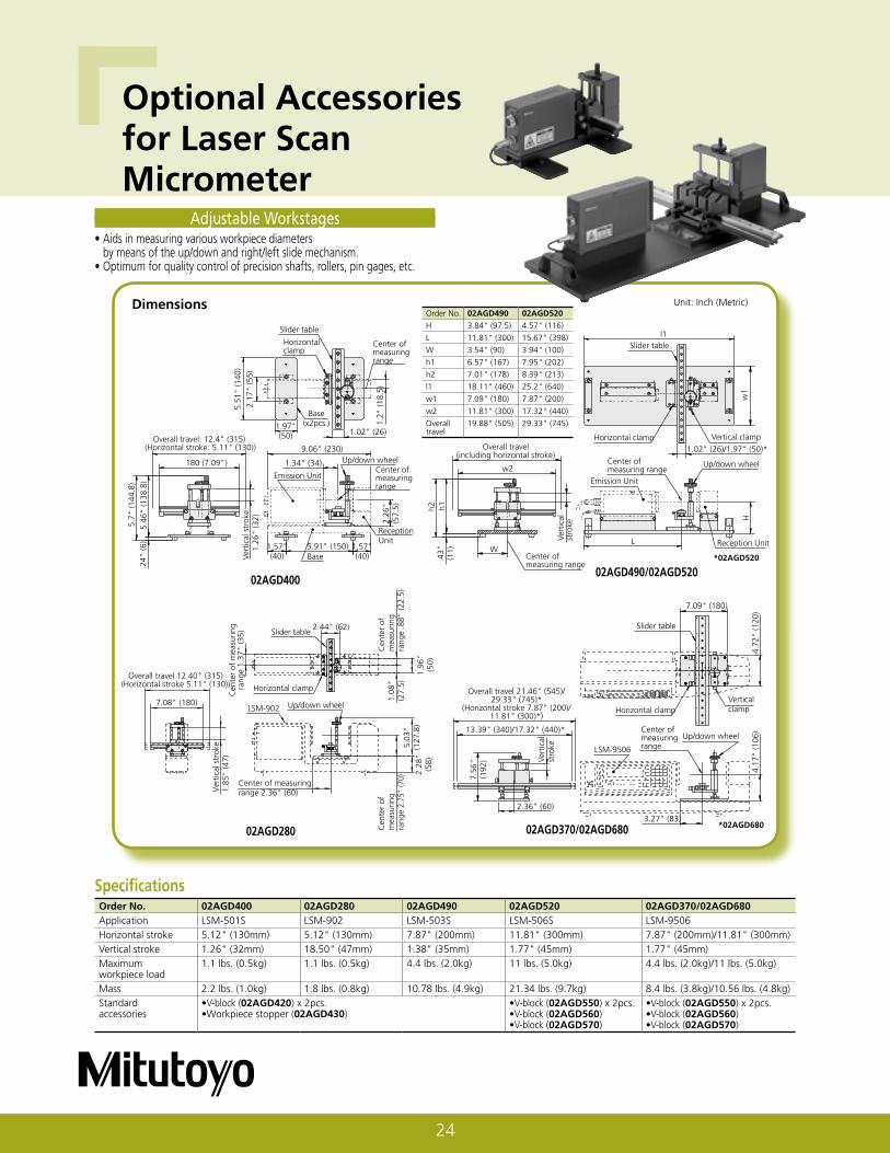
Adjustable Workstages• Aids in measuring various workpiece diameters
by means of the up/down and right/left slide mechanism.• Optimum for quality control of precision shafts, rollers, pin gages, etc.
02AGD400
Specifi cationsOrder No. 02AGD400 02AGD280 02AGD490 02AGD520 02AGD370/02AGD680Application LSM-501S LSM-902 LSM-503S LSM-506S LSM-9506Horizontal stroke 5.12" (130mm) 5.12" (130mm) 7.87" (200mm) 11.81" (300mm) 7.87" (200mm)/11.81" (300mm)Vertical stroke 1.26" (32mm) 18.50" (47mm) 1.38" (35mm) 1.77" (45mm) 1.77" (45mm)Maximum workpiece load
1.1 lbs. (0.5kg) 1.1 lbs. (0.5kg) 4.4 lbs. (2.0kg) 11 lbs. (5.0kg) 4.4 lbs. (2.0kg)/11 lbs. (5.0kg)
Mass 2.2 lbs. (1.0kg) 1.8 lbs. (0.8kg) 10.78 lbs. (4.9kg) 21.34 lbs. (9.7kg) 8.4 lbs. (3.8kg)/10.56 lbs. (4.8kg)Standard accessories
•V-block (02AGD420) x 2pcs.•Workpiece stopper (02AGD430)
•V-block (02AGD550) x 2pcs.•V-block (02AGD560)•V-block (02AGD570)
•V-block (02AGD550) x 2pcs.•V-block (02AGD560)•V-block (02AGD570)
Order No. 02AGD490 02AGD520
H 3.84" (97.5) 4.57" (116)
L 11.81" (300) 15.67" (398)
W 3.54" (90) 3.94" (100)
h1 6.57" (167) 7.95" (202)
h2 7.01" (178) 8.39" (213)
l1 18.11" (460) 25.2" (640)
w1 7.09" (180) 7.87" (200)
w2 11.81" (300) 17.32" (440)
Overall travel
19.88" (505) 29.33" (745)
02AGD280
Optional Accessoriesfor Laser Scan Micrometer
Unit: Inch (Metric)
25
L4
W
L3
A (Horizontal stroke)
W
Sliding knob
H1
H3H
2
L2 L1Fixed side Adjustable side
W
Up/down wheel
H
L
A (V
ertic
al s
trok
e)
Center Supports• Optional accessories for adjustable workstages.
V-Blocks Workpiece Stopper (02AGD430)
SpecificationsOrder No. 02AGD450 02AGD590Application Adjustable workstage for
LSM-501S (02AGD400),Adjustable workstage forLSM-902 (02AGD280),Adjustable workstage forLSM-503S (02AGD490)
Adjustable workstage forLSM-506S (02AGD520),Adjustable workstage forLSM-9506 (02AGD680)
Vertical stroke (A) .79" (20mm) 1.38" (35mm)Maximum workpiece diameter
1.18" (30mm) 2.36" (60mm)
Mass .21 lbs. (0.1kg) .44 lbs. (0.2kg)
Adjustable V-Blocks• Optional accessories for adjustable workstages.
.78"(20)
1.06"(27)
1.38
"(3
5)
• Used with 02AGD400, 02AGD280 or 02AGD490 adjustable workstage for positioning the workpiece.
• Mass: 0.05kg
SpecificationsOrder No. 02AGD440 02AGD580Application Adjustable workstage for
LSM-501S (02AGD400),Adjustable workstage forLSM-902 (02AGD280),Adjustable workstage forLSM-503S (02AGD490)
Adjustable workstage forLSM-506S (02AGD520),Adjustable workstage forLSM-9506 (02AGD680)
Point angle 60° 60°Maximum workpiecelength
4.33" (110mm)on 02AGD400/02AGD2809.06" (230mm) on 02AGD490
12.4" (315mm)on 02AGD520on 02AGD680
Horizontal stroke (A)
.2" (5mm) or more .39" (10mm) or more
Center point feeding force
1.1kgf 3.2kgf
Mass .4 lbs. (0.18kg) 1.87 lbs. (0.85kg)
Order No. 02AGD440 02AGD580
H1 1.77" (45) 2.56" (65)
H2 1.57" (40) 2.36" (60)
H3 1.18" (30) 1.77" (45)
L1 .98" (25) 1.97" (50)
L2 .79" (20) 1.57" (40)
L3 2.60" (66) 4.19" (106.5)
L4 1.26" (32) 2.17" (55)
W 1.06" (27) 1.97" (50)
Order No. 02AGD450 02AGD590
H 3.1" (78.8) 4.17" (105.8)
L 1.42" (36) 1.57" (40)
W 1.06" (27) 1.97" (50)
Order No. 02AGD420 02AGD550ØD max. 1.18" (30)* 2.36" (60)Ød max. 1.18" (30)* 2.36" (60)D - d max. .98" (25)** 1.18" (30)*H 1" (25.5) 1.54" (39)L1 1.06" (27) 1.97" (50)L2 .79" (20) 1.18" (30)*Mass 0.03kg 0.12kgCalibrationgages to beused
• Ø0.1mm• Ø1mm• Ø10mm• Ø30mm
• Ø10mm• Ø30mm
*.39" (10) for LSM-501S**.98" (25) for LSM-902
Order No. 02AGD560 02AGD570ØD max. 2.36" (60) 2.36" (60)Ød max. 1.18" (30) 1.18" (30)*D - d max. 1.97" (50) 1.97" (50)H 1.77" (45) 1.77" (45)L1 1.97" (50) 1.97" (50)L2 1.18" (30)* 1.18" (30)*Mass 0.15kg 0.15kgCalibrationgages to beused
• Ø10mm• Ø30mm• Ø60mm
• Ø1mm• Ø10mm• Ø30mm
ø.39" (10mm)
.24"(6mm)
øD
ød
Workpiece having co-axial steps
H
L1L2
Calibration gagemounting hole
Optional Accessories for Laser Scan Micrometer
26
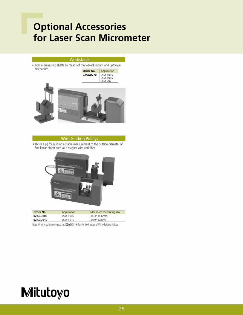
Workstage• Aids in measuring shafts by means of the V-block mount and up/down
mechanism.Order No. Application02AGD270 LSM-501S
LSM-503SLSM-902
Wire Guiding Pulleys• This is a jig for guiding a stable measurement of the outside diameter of
fine linear object such as a magnet wire and fiber.
Order No. Application Maximum measuring dia.02AGD200 LSM-500S .063" (1.6mm)02AGD210 LSM-501S .079" (2mm)
Note: Use the calibration gage set (02AGD110) for the both types of Wire Guiding Pulleys.
Optional Accessories for Laser Scan Micrometer
27
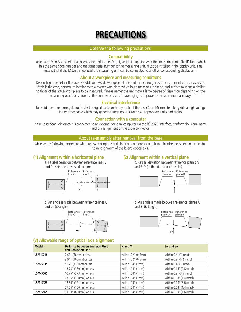
(3) Allowable range of optical axis alignmentModel Distance between Emission Unit
and Reception UnitX and Y θx and θy
LSM-501S 2.68" (68mm) or less within .02" (0.5mm) within 0.4° (7 mrad)3.94" (100mm) or less within .02" (0.5mm) within 0.3° (5.2 mrad)
LSM-503S 5.12" (130mm) or less within .04" (1mm) within 0.4° (7 mrad)13.78" (350mm) or less within .04" (1mm) within 0.16° (2.8 mrad)
LSM-506S 10.75" (273mm) or less within .04" (1mm) within 0.2° (3.5 mrad)27.56" (700mm) or less within .04" (1mm) within 0.08° (1.4 mrad)
LSM-512S 12.64" (321mm) or less within .04" (1mm) within 0.18° (3.6 mrad)27.56" (700mm) or less within .04" (1mm) within 0.08° (1.4 mrad)
LSM-516S 31.50" (800mm) or less within .04" (1mm) within 0.09° (1.6 mrad)
(2) Alignment within a vertical planec. Parallel deviation between reference planes A and B: Y (in the direction of height)
d. An angle is made between reference planes A and B: θy (angle)
(1) Alignment within a horizontal plane a. Parallel deviation between reference lines C
and D: X (in the traverse direction)
b. An angle is made between reference lines C and D: θx (angle)
About re-assembly after removal from the baseObserve the following procedure when re-assembling the emission unit and reception unit to minimize measurement errors due
to misalignment of the laser's optical axis.
Observe the following precautions.
CompatibilityYour Laser Scan Micrometer has been calibrated to the ID Unit, which is supplied with the measuring unit. The ID Unit, which
has the same code number and the same serial number as the measuring unit, must be installed in the display unit. This means that if the ID Unit is replaced the measuring unit can be connected to another corresponding display unit.
About a workpiece and measuring conditionsDepending on whether the laser is visible or invisible workpiece shape and surface roughness, measurement errors may result. If this is the case, perform calibration with a master workpiece which has dimensions, a shape, and surface roughness similar to those of the actual workpiece to be measured. If measurement values show a large degree of dispersion depending on the
measuring conditions, increase the number of scans for averaging to improve the measurement accuracy.
Electrical interferenceTo avoid operation errors, do not route the signal cable and relay cable of the Laser Scan Micrometer along side a high-voltage
line or other cable which may generate surge noise. Ground all appropriate units and cables.
Connection with a computerIf the Laser Scan Micrometer is connected to an external personal computer via the RS-232C interface, conform the signal name
and pin assignment of the cable connector.
PRECAUTIONS
Sensor Systems
Aurora, Illinois(Corporate Headquarters)(630) 978-5385Westford, Massachusetts(978) 692-8765Huntersville, North Carolina(704) 875-8332Mason, Ohio(513) 754-0709Plymouth, Michigan(734) 459-2810City of Industry, California(626) 961-9661Kirkland, Washington(408) 396-4428
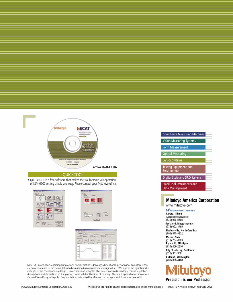
QUICKTOOL• QUICKTOOL is a free software that makes the troublesome key operation
of LSM-6200 setting simple and easy. Please contact your Mitutoyo office.
© 2006 Mitutoyo America Corporation, Aurora IL We reserve the right to change specifications and prices without notice. 0106-17 • Printed in USA • February 2006
Note: All information regarding our products (the illustrations, drawings, dimensional, performance and other techni-cal data) contained in this pamphlet, is to be regarded as approximate average values. We reserve the right to make changes to the corresponding designs, dimensions and weights. The stated standards, similar technical regulations, descriptions and illustrations of the products were valid at the time of printing. The latest applicable version of our General Sales Policy will apply. Only quotations submitted by Mitutoyo or our approved distributors are valid.
Part No. 02AGC830A