land 17 artillery replacement project self-propelled howitzermarkwr.mailcan.com/t5c/091 sow...
TRANSCRIPT

UNCONTROLLED COPY WHEN PRINTED
DEF(AUST) 8484 / Issue 1 Dated 20 Sep 2007
LAND 17 Artillery Replacement Project
SELF-PROPELLED HOWITZER
Function and Performance Specification
* PUBLISHED UNDER AUTHORITY OF DEPARTMENT OF DEFENCE
USAGE: Land NSC:
AUSTRALIAN GOVERNMENT AUSTRALIAN DEFENCE STANDARD
UNCONTROLLED COPY WHEN PRINTED
DEF(AUST) 8484 / Issue 1
DOCUMENT MANAGEMENT INFORMATION This page lists the ownership and area responsible for providing final approval or acceptance for the document. Defence Group: Defence Materiel Organisation Sponsoring Organisation: Land Systems Division Sponsoring Appointment: Director Combat Support Systems Program Office Specification Author: LAND 17 Systems Engineering Group Approved: 20 Sep 2007 Design Acceptance Authority: Mr Sam Brugliera Approved: 20 Sep 2007 Executive Authority: LTCOL Steve Hume Approved: 20 Sep 2007 This document is the property of the Department of Defence This Document and associated documentation may be used only for the specific enquires, tenders or orders, placed by an Officer for the Department of Defence and is not to be used for any other purpose whatsoever, without the express written sanction of the Sponsoring Coordinator named above. No copies of this Document in whole or in part may be made without the permission of the Sponsoring Coordinator. Any questions regarding this document should be addressed to the authority named in the tender schedule.
WARNING
This Specification may call for the use of substances and test procedures that may be injurious to health if adequate precautions are not taken. It refers only to technical suitability and in no way absolves either the supplier or user from statutory obligations relating to health and safety at any stage of manufacture or use.

UNCONTROLLED COPY WHEN PRINTED
AMENDMENT LIST
AMENDMENT
EFFECTED
NO
DATED
SIGNATURE
DATE
Issue 1 20 Sep 2007


Contents
1 1SCOPE1.1 1Identification
1.2 1System Overview
1.3 2Document Overview
2 5APPLICABLE DOCUMENTS
3 6REQUIREMENTS3.1 6Missions
3.1.1 6Support the Close Battle
3.1.2 7Shape the Battlespace
3.2 7System Boundaries & Context
3.3 9Not Used
3.4.1 9General
3.4.2 9Ordnance
3.4.2.1 9Common Requirements
3.4.2.2 9Self-Propelled Howitzer Requirements
3.4.3 12Accuracy
3.4.3.1 12Common Requirements
3.4.3.2 12Self-Propelled Howitzer Requirements
3.4.4 13Consistency
3.4.4.1 13Common Requirements
3.4.4.2 13Self-Propelled Howitzer Requirements
3.4.5 13Rates of Fire
3.4.5.1 13Common Requirements
Contents COMMERCIAL-IN-CONFIDENCE Page i
LAND 17 - DEF(AUST) 8484 - Version: 5.0 COMMERCIAL-IN-CONFIDENCE Printed 22 September 2007

3.4.5.2 13Self-Propelled Howitzer Requirements
3.4.6 14Indirect Fire Capability & Range
3.4.6.1 14Common Requirements
3.4.6.2 15Self-Propelled Howitzer Requirements
3.4.7 16Direct Fire Capability & Range
3.4.7.1 16Common Requirements
3.4.7.2 17Self-Propelled Howitzer Requirements
3.4.8 18Terrain
3.4.8.1 18Common Requirements
3.4.8.2 18Self-Propelled Howitzer Requirements
3.4.9 18Survey System
3.4.9.1 18Common Requirements
3.4.9.2 21Self-Propelled Howitzer Requirements
3.4.10 21Munitions
3.4.10.1 22Common Requirements
3.4.10.2 23Self-Propelled Howitzer Requirements
3.4.11 23Battle Management System - Fires
3.4.11.1 24Background
3.4.11.2 24Battle Management System Common Requirements
3.4.11.3 51BMS-F(C2)
3.4.11.4 56BMS-F(FO)
3.4.11.5 69BMS-F(FCS) Self-Propelled Howitzer Requirements
3.4.12 72Platform/Vehicle
3.4.12.1 72Common Requirements
3.4.12.2 75Self-Propelled Howitzer Requirements
3.5 117Availability
3.6 117Reliability
3.6.1 117General
Contents COMMERCIAL-IN-CONFIDENCE Page ii
LAND 17 - DEF(AUST) 8484 - Version: 5.0 COMMERCIAL-IN-CONFIDENCE Printed 22 September 2007

3.6.2 118Basic Reliability
3.6.3 118Mission Reliability
3.7 118Maintainability
3.7.1 118General
3.7.2 118Corrective Maintenance
3.7.2.1 118Operator Corrective Maintenance
3.7.2.2 119Light Grade Corrective Maintenance
3.7.2.3 119Medium Grade Corrective Maintenance
3.7.2.4 119Heavy Grade Corrective Maintenance
3.7.3 120Preventative Maintenance
3.8 120Deployability
3.8.1 120General
3.8.2 120AQIS Requirements
3.8.3 120Common Deployability
3.8.4 121Self-Propelled Howitzer Deployability
3.9 123Transportability
3.9.1 123General
3.9.2 123Common Transportability
3.9.3 123Self-Propelled Howitzer Transportability
3.10 123Environmental Conditions
3.10.1 123Common Environmental Requirements
3.10.1.1 124Climate
3.10.1.2 124Altitude
3.10.1.3 125Operating & Storage Temperature Ranges
3.10.1.4 126Direct Solar Radiation
3.10.1.5 126Driving Rain
3.10.1.6 127Dust & Sand Exposure
3.10.1.7 128Ice Conditions
Contents COMMERCIAL-IN-CONFIDENCE Page iii
LAND 17 - DEF(AUST) 8484 - Version: 5.0 COMMERCIAL-IN-CONFIDENCE Printed 22 September 2007

3.10.1.8 128Shock & Vibration
3.10.1.9 130Biological Growth
3.10.2 130Self-Propelled Howitzer Environmental Requirements
3.11 130Electromagnetic Radiation
3.11.1 130General
3.11.2 131Common Electromagnetic Radiation Requirements
3.11.2.1 131EMC/EW
3.11.3 132Self-Propelled Howitzer Electromagnetic Radiation Requirements
3.11.3.1 132TEMPEST
3.12 132Architecture, Growth & Expansion
3.12.1 133Common Architecture, Growth & Expansion Requirements
3.12.1.1 133Computer Hardware Resource Utilisation
3.12.1.2 133Platform Electrical Power Supply
3.12.2 133Self-Propelled Howitzer Architecture, Growth & Expansion Requirements
3.13 133Safety
3.13.1 133Common Safety
3.13.2 134Electrical Safety
3.13.2.1 134Common Electrical Safety Requirements
3.13.2.2 134Self-Propelled Howitzer Electrical Safety Requirements
3.13.3 134Mechanical Safety
3.13.3.1 134Common Mechanical Safety Requirements
3.13.3.2 134Self-Propelled Howitzer Mechanical Safety Requirements
3.13.4 134Acoustic Safety
3.13.4.1 134General
3.13.4.2 134Common Acoustic Safety Requirements
3.13.4.3 135Self-Propelled Howitzer Acoustic Safety Requirements
3.13.5 136Fire Safety
3.13.5.1 136Common Fire Safety Requirements
Contents COMMERCIAL-IN-CONFIDENCE Page iv
LAND 17 - DEF(AUST) 8484 - Version: 5.0 COMMERCIAL-IN-CONFIDENCE Printed 22 September 2007
3.13.5.2 136Self-Propelled Howitzer Fire Safety Requirements
3.13.6 139Explosive Safety
3.13.6.1 139Common Explosive Safety
3.13.6.2 139Self-Propelled Howitzer Explosive Safety Requirements
3.13.7 139Radiation Hazards
3.13.7.1 139Common Radiation Hazards Requirements
3.13.7.2 140Self-Propelled Howitzer Radiation Hazards Requirements
3.13.8 140Hazardous Substances
3.13.8.1 140Common Hazardous Substances Requirements
3.13.8.2 140Self-Propelled Howitzer Hazardous Substances Requirements
3.13.9 140Ozone Depleting Substances
3.13.9.1 140Common Ozone Depleting Substances Requirements
3.13.9.2 140Self-Propelled Howitzer Ozone Depleting Substances Requirements
3.13.10 140Equipment Handling
3.13.10.1 140Common Equipment Handling Requirements
3.13.10.2 141Self-Propelled Howitzer Equipment Handling Requirements
3.14 141Environmental Compliance Requirements
3.14.1 141Common Environmental Compliance Requirements
3.14.2 141Self-Propelled Howitzer Environmental Impact Requirements
3.15 141Usability & Human Factors
3.15.1 141Common Usability & Human Factors
3.15.1.1 142General
3.15.2 142Self-Propelled Howitzer Usability & Human Factors
3.15.2.1 142General
3.16 143Security & Privacy
3.16.1 143Common Security & Privacy Requirements
3.16.2 144Self-Propelled Howitzer Security & Privacy Requirements
3.17 144Adaptation Requirements
Contents COMMERCIAL-IN-CONFIDENCE Page v
LAND 17 - DEF(AUST) 8484 - Version: 5.0 COMMERCIAL-IN-CONFIDENCE Printed 22 September 2007

3.17.1 144Common Adaptation Requirements
3.17.2 144Self-Propelled Howitzer Adaptation Requirements
3.18 144Design & Implementation Constraints
3.18.1 144Common Design & Implementation Constraints
3.18.1.1 144Identifying Markings
3.18.1.2 145Standardisation and Interoperability
3.18.1.3 145Construction Constraints
3.18.1.4 146Paints and Finishes
3.18.1.5 150Painting of Ordnance
3.18.2 150Self-Propelled Howitzer Design & Implementation Constraints
3.18.2.1 150General
3.18.2.2 151Identifying Markings
3.18.2.3 151Instruction and Identification Plates
3.18.2.4 152Signature Management
3.18.2.5 153Marker Fittings
3.19 153System Interface Requirements
3.19.1 153Common System Interface Requirements
3.19.1.1 153Interface 1
3.19.1.2 154Interface 2
3.19.2 155Self-Propelled Howitzer System Interface Requirements
4 156PRECEDENCE & CRITICALITY OF REQUIREMENTS
5 158VERIFICATION5.1 158General
5.2 158Methods of Verification
6 159REQUIREMENTS TRACEABILITY
7 160NOTES
Contents COMMERCIAL-IN-CONFIDENCE Page vi
LAND 17 - DEF(AUST) 8484 - Version: 5.0 COMMERCIAL-IN-CONFIDENCE Printed 22 September 2007

7.1 160General
7.2 160Abbreviations & Acronyms
7.3 160Glossary
Contents COMMERCIAL-IN-CONFIDENCE Page vii
LAND 17 - DEF(AUST) 8484 - Version: 5.0 COMMERCIAL-IN-CONFIDENCE Printed 22 September 2007

DMO COMMERCIAL-IN-CONFIDENCE Page 1 of 161
LAND 17 - DEF(AUST) 8484 - Version: 5.0 COMMERCIAL-IN-CONFIDENCE Printed 22 September 2007
ID
FPS-1
FPS-2
FPS-50
FPS-4318
FPS-4248
FPS-3
FPS-51
FPS-52
FPS-53
Paragraph
1
1.1
1.1.1
1.1.2
1.1.3
1.2
1.2.1
1.2.2
1.2.3
Description
1 SCOPE1.1 Identification
This document, DEF(AUST) 8484 - Artillery Replacement Project Functional Performance Specification (LAND 17), specifies the functional, performance and other technical requirements for Request For Tender (RFT) L17-07-RFT-SPH- Project LAND 17 (Artillery Replacement).
This document is divided into LAND 17 common requirements and requirements specific to each identified sub-system. Tenderers are provided with all common requirements plus those requirements relating to the package of interest. Additional requirements are provided as Advice clauses where necessary to assist understanding.
This Specification has been structured for commercial release and control as specified in the contractual documents.
1.2 System Overview
Project LAND 17 (Artillery Replacement) will assist in maximising the ADF's fighting power through the delivery of a networked, enduring, all weather indirect fire capability that is modular, provides scaleable and precise lethal and non-lethal effects, coordinates all available joint and coalition fires and interfaces with the ADF's networked manoeuvre and Surveillance and Target Acquisition assets. It will be primarily structured and organised to provide close support artillery and also provide the ADF manoeuvre commander with an improved ability to conduct depth/shaping operations through the systems access to organic (to Army) long range precision fires. Close support artillery is the engagement of targets of immediate concern to manoeuvre units and the provision of timely, intimate, offensive and defensive fire to those units. The LAND 17 system shall provide the ability for tactical control and coordination of Joint and Coalition assets. This control and coordination will be performed through data enabled systems.
LAND 17 will be a system of systems. Five sub-systems have been identified in the Indirect Fire System (IFS) -Operational Concept Document (OCD) which was endorsed by the Defence Capability Committee (DCC) in October 2004 and in documentation presented to Government at First Pass. These sub-systems are:- Ammunition,- Target acquisition,- Command and control,- Delivery platforms, and- Combat service support.
These sub-systems will constitute both the Mission System and the Support System, and combine to generate and coordinate indirect fire, and other joint and coalition lethal and non-lethal effects across the land battlespace.
Rating
N/A
N/A
Advice
Advice
Advice
N/A
Advice
Advice
Advice
Verification
N/A
N/A
N/A
N/A
N/A
N/A
N/A
N/A
N/A

DMO COMMERCIAL-IN-CONFIDENCE Page 2 of 161
LAND 17 - DEF(AUST) 8484 - Version: 5.0 COMMERCIAL-IN-CONFIDENCE Printed 22 September 2007
ID
FPS-54
FPS-55
FPS-4
FPS-56…
Paragraph
1.2.4
1.2.5
1.3
1.3.1
Description
LAND 17 will provide the ADF with an enhanced Indirect Fire support capability through to approximately 2025-2030. The enhanced capability will be achieved by either replacement or enhancement of each existing sub-system (or elements within it).
LAND 17 will seek to achieve a range of contract deliverables including:Precision enhancements for general natures of munitions, offering greater precision at range (specifically Course Correcting Fuses);Provision of a Battle Management System - Fires (BMS-F) that will network the terminal control elements (FO), C2/tactical coordination and fire direction elements (JOSCC and FDCs), and the launcher platforms. The BMS-F will integrate all components of the system into an efficient, networked structure. The BMS-F will tactically coordinate and terminally control land based fires as well as Offensive Air Support (OAS) and Naval Surface Fire Support (NSFS);Provision of upgraded or new firing platforms, Able to deliver indirect fire support to ADF manoeuvre units at greater ranges, and with enhanced efficiency, effectiveness and responsiveness. Different solutions will be required to meet the deployment and capability needs of different land force formations; and Provision of upgraded or new target acquisition equipment for the FO suitable for the tactical control and coordination of joint fires with the ability to provide targeting data to all ADF response platforms (OAS and NSFS).
1.3 Document Overview
Following the guidance provided by the Capability Document Definition Guide, this document is laid out in the following manner:Main Body:a. Section 1 - Scope;b. Section 2 - Applicable Documents;c. Section 3 - Requirements
i. Section 3.1 - Missions;ii. Section 3.2 - System Boundaries & Controls;iii. Section 3.3 - Not Used;iv. Section 3.4 - System Capability Requirements;v. Section 3.5 - Availability;vi. Section 3.6 - Reliability;vii. Section 3.7 - Maintainability;viii. Section 3.8 - Deployability;ix. Section 3.9 - Transportability;x. Section 3.10 - Environmental Conditions;xi. Section 3.11 - Electromagnetic Radiation;xii. Section 3.12 - Architecture, Growth & Expansion;xiii. Section 3.13 - Safety;xiv. Section 3.14 - Environmental Impact Requirements;xv. Section 3.15 - Usability & Human Factors;
Rating
Advice
Advice
N/A
Advice
Verification
N/A
N/A
N/A
N/A

DMO COMMERCIAL-IN-CONFIDENCE Page 3 of 161
LAND 17 - DEF(AUST) 8484 - Version: 5.0 COMMERCIAL-IN-CONFIDENCE Printed 22 September 2007
ID
FPS-56
FPS-4470
FPS-4471
FPS-4472
FPS-4473
FPS-4474
FPS-4475
FPS-4476
FPS-4477
FPS-4478
Paragraph
1.3.2
1.3.2.1
1.3.2.2
1.3.2.3
1.3.2.4
1.3.2.5
1.3.2.6
1.3.2.7
1.3.2.8
Description
xvi. Section 3.16 - Security & Privacy;xvii. Section 3.17 - Adaptation Requirements;xviii. Section 3.18 - Design & Implementation Constraints;xvix Section 3.19 - System Interface Requirements;
d. Section 4 - Precedence & Criticality of Requirements;e. Section 5 - Verification
i Section 5.1 - General;ii Section 5.2 - Methods of Verification;
f. Section 6 - Requirements Traceability;g. Section 7 - Notes
i. Section 7.1 - General;ii Section 7.2 - Abbreviations & Acronyms; andiii Section 7.3 - Glossary
Annexes:Tenderers who indicate that they Fully Comply with each Annex listed below have confirmed that they have read and understood the contents of each Annex.
a. Annex A - Equipment List;
b. Annex B - Human Ergonomics;
c. Annex C - Applicable Documents, Abbreviations, Acronyms and Glossary;
d. Annex D - Climate and Environment;
e. Annex E - Mobility Categories;
f. Annex F - In-service 155mm Munitions;
g. Annex G - Definition of Standard & Assisted HE Projectiles; and
h. Annex H - K Series Messages.
Rating
Advice
Advice
Advice
Advice
Advice
Advice
Advice
Advice
Advice
Verification
N/A
N/A
N/A
N/A
N/A
N/A
N/A
N/A
N/A

DMO COMMERCIAL-IN-CONFIDENCE Page 4 of 161
LAND 17 - DEF(AUST) 8484 - Version: 5.0 COMMERCIAL-IN-CONFIDENCE Printed 22 September 2007
ID
FPS-2127
FPS-2128
FPS-2129
FPS-2130
FPS-2131
Paragraph
1.3.3
1.3.4
1.3.5
1.3.6
1.3.7
Description
Following Cabinet approval at First Pass, the capabilities for LAND 17 have been broken up into three main sections:a. Common;b. Self-Propelled Howitzer (SPH); andc. Lightweight Towed Howitzer (LW155).
The Common sections contain all those requirements that are applicable to all potential solution variants and must be addressed by all Suppliers proposing systems and equipment.
The SPH sections contain all those requirements that are specific to potential SPH solution variants and must be addressed by Suppliers proposing SPH systems and equipment.
The LW155 sections contain all those requirements that are specific to potential LW155 solution variants and must be addressed by Suppliers proposing LW155 systems and equipment.
If a chapter of the document does not have separate Common, SPH and / or LW155 sections then it is to be read as a Common chapter applying to all variants of the LAND 17 system.
Rating
Advice
Advice
Advice
Advice
Advice
Verification
N/A
N/A
N/A
N/A
N/A

DMO COMMERCIAL-IN-CONFIDENCE Page 5 of 161
LAND 17 - DEF(AUST) 8484 - Version: 5.0 COMMERCIAL-IN-CONFIDENCE Printed 22 September 2007
ID
FPS-5
FPS-6
FPS-7
Paragraph
2
2.1
2.2
Description
2 APPLICABLE DOCUMENTSIn the event of a conflict between the text of this Specification and the references cited herein, the text of this Specification takes precedence to the extent required to resolve the conflict. Nothing in this Specification, however, supersedes applicable laws and regulations unless a specific exception has been obtained.
For the list of Applicable Documents refer to Annex C of this Specification.
Rating
N/A
Advice
Advice
Verification
N/A
N/A
N/A

DMO COMMERCIAL-IN-CONFIDENCE Page 6 of 161
LAND 17 - DEF(AUST) 8484 - Version: 5.0 COMMERCIAL-IN-CONFIDENCE Printed 22 September 2007
ID
FPS-8
FPS-9
FPS-385
FPS-386
FPS-388
FPS-389…
Paragraph
3
3.1
3.1.1
3.1.1
3.1.1.1
3.1.1.2
Description
3 REQUIREMENTS3.1 Missions
The mission for the LAND 17 system is to establish such fire supremacy in the battlespace that threats can neither interfere with friendly operations nor effectively develop their own. To achieve this mission, the system must complete two essential tasks. Those tasks are to:a. provide protective Indirect Fire to support the close battle; andb. employ Indirect Fire to shape the battlespace.
3.1.1 Support the Close Battle
The LAND 17 system is required to suppress, neutralise and destroy threat targets in support of the land forces in the close battle on the complex battlefield. These are tactical engagements that will occur in close proximity to our ground forces and often with little warning. In these cases, the generation of fire supremacy will need to be responsive, accurate and scalable. Essential to these engagements is the coordination and delivery of Joint and Coalition lethal and non-lethal effects in both time and space against targets that are of immediate concern, and in close proximity, to ground forces. This type of fire is usually protective in nature. Joint and Coalition control and coordination for NSFS and OAS will be via the LAND 17 BMS-F with established protocols.
The offensive support system supporting the close battle must possess similar mobility and protection as the supported force, and have sufficient range coverage (both maximum and minimum) to obviate the need for redeployment in order to support ground forces. This will enhance the manoeuvrecommander's ability to create tempo. Specific types of Joint and Coalition fires required to achieve this task area. Preparatory Fire. Preparatory fire is employed in support of an assault and aims to weaken the enemy's resistance by disrupting, disorganising or neutralising their defence; or by demoralising the enemy so that they will offer little or no resistance to the assaultb. Covering Fire. Covering fire is employed during the attack and counter-attack to protect assaulting troops by neutralising or suppressing enemy direct fire weapons. Neutralisation is achieved when the enemy is prevented from manoeuvring, observing ground forces and using weapons effectively. Covering fire needs to be potentially lethal, intense and continuous.c. Defensive Fire. Defensive fire is designed to disorganise enemy preparations for an attack or counter-attack and to break up their assault.d. Destruction. Through the use of precision munitions, artillery will be Capable of performing destruction of hardened targets in support of the close and deep battle, including those in urban and complex/restricted terrain, while limiting collateral damage. Destructive fires must not only destroy hardened targets, but with minimal adverse effects on non-targets and supported forces. Munitions must provide the needed lethality, as well as the capability to deliver controlled, lethal effects specifically where they are needed. Destructive fires will need to be accurate, responsive, and primarily with an autonomous capability (fire & forget) or terminally guided for additional flexibility and accuracy (Semi Active
Rating
N/A
N/A
Advice
N/A
Advice
Advice
Verification
N/A
N/A
N/A
N/A
N/A
N/A
DMO COMMERCIAL-IN-CONFIDENCE Page 7 of 161
LAND 17 - DEF(AUST) 8484 - Version: 5.0 COMMERCIAL-IN-CONFIDENCE Printed 22 September 2007
ID
FPS-389
FPS-387
FPS-390
FPS-23
FPS-2519
…
Paragraph
3.1.2
3.1.2.1
3.2
3.2.1
Description
Laser). Accurate and responsive are adequate requirements for the balance of conventional munitions in service through the use of add on course correcting fuses. In many scenarios, external designation (like lasers) to guide precision munitions - requiring eyes-on-target - is not feasible. In those situations, autonomous munitions (GPS/INS, MMW, IR, etc) are necessary. In other scenarios, particularly in close support where close-in effects are needed, externally designated munitions (like SAL) to provide pinpoint effects will be beneficial.
3.1.2 Shape the Battlespace
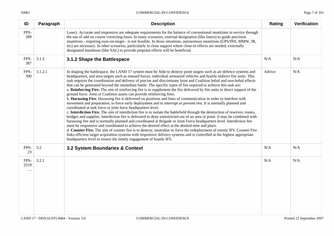
In shaping the battlespace, the LAND 17 system must be Able to destroy point targets such as air defence systems and headquarters, and area targets such as massed forces, individual armoured vehicles and hostile indirect fire units. This task requires the coordination and delivery of precise and discriminate Joint and Coalition lethal and non-lethal effects that can be generated beyond the immediate battle. The specific types of fire required to achieve this task are:a. Reinforcing Fire. The aim of reinforcing fire is to supplement the fire delivered by fire units in direct support of the ground force. Joint or Coalition assets can provide reinforcing fires.b. Harassing Fire. Harassing fire is delivered on positions and lines of communication in order to interfere with movement and preparation, to force early deployment and to interrupt or prevent rest. It is normally planned and coordinated at task force or joint force headquarters level.c. Interdiction Fire. The aim of interdiction fire is to isolate the battlefield through the destruction of reserves, routes, bridges and supplies. Interdiction fire is delivered to deny unrestricted use of an area or point. It may be combined with harassing fire and is normally planned and coordinated at Brigade or Joint Force headquarters level. Interdiction fire must be responsive and coordinated to achieve the desired effect at the desired time and place.d. Counter Fire. The aim of counter fire is to destroy, neutralise or force the redeployment of enemy IFS. Counter Fire links efficient target acquisition systems with responsive delivery systems and is controlled at the highest appropriate headquarters level to ensure the timely engagement of hostile IFS.
3.2 System Boundaries & Context
Rating
N/A
Advice
N/A
N/A
Verification
N/A
N/A
N/A
N/A
DMO COMMERCIAL-IN-CONFIDENCE Page 8 of 161
LAND 17 - DEF(AUST) 8484 - Version: 5.0 COMMERCIAL-IN-CONFIDENCE Printed 22 September 2007
ID
FPS-2519
FPS-1472
Paragraph
3.2.1.1
Description
Army's Future Offensive Support System
(AFOSS)A system of systems,
characterized by responsiveness, high tactical
mobility, greater autonomy and survivability
IFS Context Diagram
DSTO- Task ARM 01/166 - IFWS C2 Architectures- Task ARM 01/375 - Weapon Performance Assessment
Others- Indirect Fire Weapons Study -Engagement Systems (Mar 03)- Land 5000 Discussion Paper (Oct 02)- AFOSS Prelininary Study (Jun 02)- DIO Land 400 Threat Study (2005) (Classified)
Studies &Analysis
Enabling Projects
Land 19 - VLLADSLand 75 - BCSS & BMS-MountedLand 112 Ph 4 - ASLAVLand 125 – BMS-DismountedLand 121 – OverlanderLand 146-2 Combat IdentificationLand 907 - Army TankJP 2072 - Land Tac CommsJP 2030 - JCSEJP 2077 Log Info Mgt systemJP 2085 EO WarstocksJP2089 Tac Info ExchangeDEF 224 -BUNYIP
Projects Providing Capability
Land 58-3 - Locating Radar LOTEAir 87 – ARHAir 9000-5 CH47D UpgradeJP2085 EO Warstocks
Minors:Laser Target DesignatorArtillery Orientation SystemLong Range Mortar (81mm ) systemMedium Artillery Replacement Ammunition Project
Coalition Environment
Joint Environment
Joint FiresOffensive Air Support:- Air 6000 NACCNaval Surface Fire Support:- SEA 4000 - AWD- SEA 1348 - ANZAC
Coalition Offensive Fires Assets
Provide target and fire mission data to coalition assets including :-artillery (tubes)-artillery (rockets)-offensive air support-naval surface fire supportReceive target and fire mission data from coalition (JOSCC equivalent) organizations.
Coalition C4ISRInterface with:- Coalition C2 systems- Coalition Indirect Fire Planning Systems (eg AFADTS) Receive and process requests for fire from coalition assets under OPCON of Aust JTF
FIC
Command & managementPersonnelOrganizationMajor systemsFacilitiesCollective TrainingSupport & Supplies
Joint C4ISR
JP 2030 - JCSEJP 129 - TAUVJP 20 89 - TIE ProgramsAIR 7000 - UAVAIR 5077 - AEW&C
23/10/2006
Project Land 17Artillery Replacement
StrategicGuidance
Defence White Paper 2000
“enhancing the current land force capabilities such as 105 mm and 155”mm field artillery”
Defence Capability Plan 2006-2016
LAND 17 - “deliver enhancements to the indirect fire system through the replacement or enhancement of the 105 mm and 155 mm howitzer fleets”
Future Warfighting ConceptsMOLE:-generate overwhelming fighting power to achieve decision- requires offensive support systems that can rapidly and simultaneously concentrate effects in different locations by day and night regardless of weather conditions.
Complex Warfighting:- close combat capability remains the key to effectiveness- force multipliers are:
- Versatility- Agility- Orchestration- Protection
Ammunition
Target Acquisition
Command & Control
Combat Service Support
Delivery Platforms
Army's Related Projects
Joint Mobility Assets
JP 2048 - ADASJP 2027 - LPA ReplacementAIR 8000 - C-130/C-17AIR 9000 - Trooplift Helo
FIC
Standardization Agreements
ABCA:- QSTAGsNATO: - Joint Ballistic MoU
Simulation & Training
Simulation requirements Individual & collective training
Indirect Fire System (IFS)project scope limitations
Course Correctin Fuses
JOST Target Acquisition Devices
Launchers
Fire Control
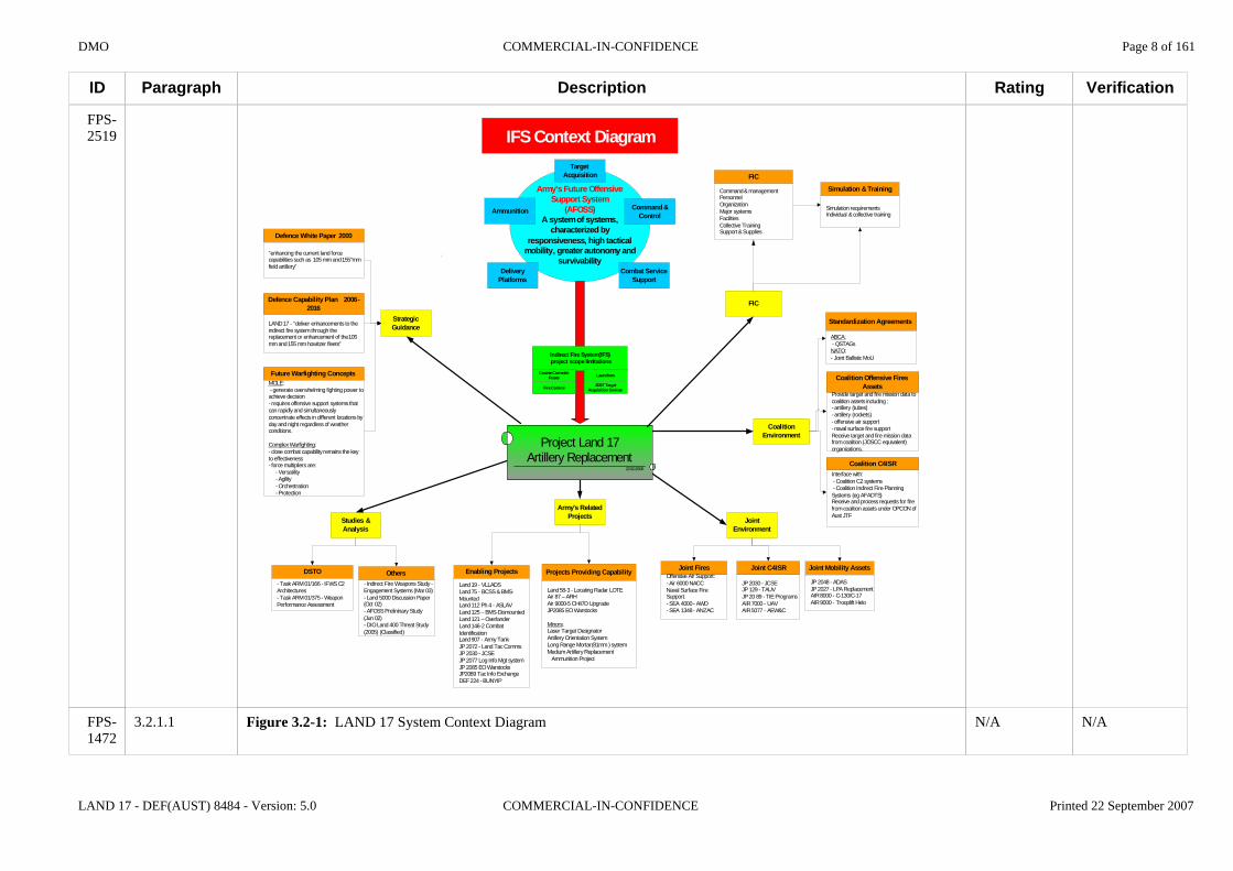
Figure 3.2-1: LAND 17 System Context Diagram
Rating
N/A
Verification
N/A

DMO COMMERCIAL-IN-CONFIDENCE Page 9 of 161
LAND 17 - DEF(AUST) 8484 - Version: 5.0 COMMERCIAL-IN-CONFIDENCE Printed 22 September 2007
ID
FPS-24
FPS-2132
FPS-1899
FPS-2133
FPS-2134
FPS-308
FPS-2135
FPS-2179
FPS-1513
FPS-299
FPS-392
FPS-393
FPS-1852
Paragraph
3.3
3.4.1
3.4.1.1
3.4.2
3.4.2.1
3.4.2.1.1
3.4.2.2
3.4.2.2.1
3.4.2.2.1.1
3.4.2.2.2
3.4.2.2.2.1
3.4.2.2.2.2
3.4.2.2.2.3
Description
3.3 Not Used
3.4.1 General
Unless explicitly stated otherwise, the LAND 17 system shall satisfy all requirements in this Specification when operated in accordance with the published operational mission profiles, in any of the environmental conditions specified herein.
3.4.2 Ordnance
3.4.2.1 Common Requirements
The ordnance of the LAND 17 system shall be a 155 mm howitzer.
3.4.2.2 Self-Propelled Howitzer Requirements
3.4.2.2.1 General
The internal dimensions and ballistics of the ordnance of the SPH shall be no less than those defined in Section 4 of DEF(AUST) 8416.
3.4.2.2.2 Barrel Freedom and Laying
The SPH shall be Able to traverse the ordnance through a firing arc of no less than 1200 Mils from centre in each direction without repositioning the weapon platform to allow coverage of minimum to maximum range without any gaps.
The SPH shall be Able to traverse the ordnance through a firing arc of 6400 Mils in either direction without repositioning the weapon platform.
The SPH shall be Able to engage targets 3200 Mils left or right of centre of arc in less than 60 seconds from the receipt of the new target Bearing until ready to fire on target.
Rating
N/A
N/A
Advice
N/A
N/A
Essential
N/A
N/A
Very Important
N/A
Essential
Desirable
Very Important
Verification
N/A
N/A
N/A
N/A
N/A
Inspect
N/A
N/A
TestConformance Statement
N/A
Demonstrate
Demonstrate
Demonstrate
DMO COMMERCIAL-IN-CONFIDENCE Page 10 of 161
LAND 17 - DEF(AUST) 8484 - Version: 5.0 COMMERCIAL-IN-CONFIDENCE Printed 22 September 2007
ID
FPS-1853
FPS-394
FPS-395
FPS-2710
FPS-2711
FPS-396
FPS-4266
FPS-397
FPS-3544
FPS-2708
FPS-301
FPS-400
FPS-401
Paragraph
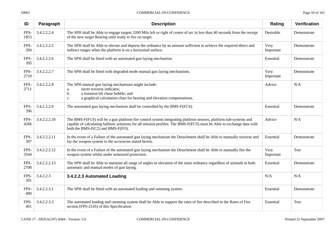
3.4.2.2.2.4
3.4.2.2.2.5
3.4.2.2.2.6
3.4.2.2.2.7
3.4.2.2.2.8
3.4.2.2.2.9
3.4.2.2.2.10
3.4.2.2.2.11
3.4.2.2.2.12
3.4.2.2.2.13
3.4.2.2.3
3.4.2.2.3.1
3.4.2.2.3.2
Description
The SPH shall be Able to engage targets 3200 Mils left or right of centre of arc in less than 40 seconds from the receipt of the new target Bearing until ready to fire on target.
The SPH shall be Able to elevate and depress the ordnance by an amount sufficient to achieve the required direct and indirect ranges when the platform is on a horizontal surface.
The SPH shall be fitted with an automated gun laying mechanism.
The SPH shall be fitted with degraded mode manual gun laying mechanisms.
The SPH manual gun laying mechanisms might include:a. turret traverse indicator;b. a trunnion tilt chase bubble; andc. a graphical calculation chart for bearing and elevation compensations.
The automated gun laying mechanism shall be controlled by the BMS-F(FCS).
The BMS-F(FCS) will be a gun platform fire control system integrating platform sensors, platform sub-systems and capable of calculating ballistic solutions for all mission profiles. The BMS-F(FCS) must be Able to exchange data with both the BMS-F(C2) and BMS-F(FO).
In the event of a Failure of the automated gun laying mechanism the Detachment shall be Able to manually traverse and lay the weapon system to the accuracies stated herein.
In the event of a Failure of the automated gun laying mechanism the Detachment shall be Able to manually fire the weapon system whilst under armoured protection.
The SPH shall be Able to maintain all range of angles in elevation of the main ordnance regardless of azimuth in both automatic and manual modes of gun laying.
3.4.2.2.3 Automated Loading
The SPH shall be fitted with an automated loading and ramming system.
The automated loading and ramming system shall be Able to support the rates of fire described in the Rates of Fire section [FPS-2145] of this Specification.
Rating
Desirable
Very Important
Essential
Very Important
Advice
Essential
Advice
Essential
Very Important
Essential
N/A
Essential
Essential
Verification
Demonstrate
Demonstrate
Demonstrate
Demonstrate
N/A
Demonstrate
N/A
Demonstrate
Test
Demonstrate
N/A
Demonstrate
Test

DMO COMMERCIAL-IN-CONFIDENCE Page 11 of 161
LAND 17 - DEF(AUST) 8484 - Version: 5.0 COMMERCIAL-IN-CONFIDENCE Printed 22 September 2007
ID
FPS-1589
FPS-402
FPS-403
FPS-3472
FPS-404
FPS-2482
FPS-405
FPS-406
FPS-407
FPS-303
FPS-1515
FPS-1372
FPS-1471
Paragraph
3.4.2.2.3.3
3.4.2.2.3.4
3.4.2.2.3.5
3.4.2.2.3.6
3.4.2.2.3.7
3.4.2.2.3.8
3.4.2.2.3.9
3.4.2.2.3.10
3.4.2.2.3.11
3.4.2.2.4
3.4.2.2.4.1
3.4.2.2.4.2
3.4.2.2.4.3
Description
The automated loading and ramming system shall be Able to achieve a consistent ram (depth of engagement of driving band for consistent shot start pressures) at all Elevations of the breech to Enable accurate fire.
The automated loading and ramming system shall insert the primer into the breech ready for firing.
For all fire missions, less Excalibur fire missions, the automated gun loading and ramming system shall, in conjunction with the gun platform and BMS-F(FCS), be Able to automatically:a. identify and select the correct projectile type; andb. for inductively set fuses, correctly set the fuse for the projectile.
For each fire mission the automated loading and ramming system shall, in conjunction with the gun platform and BMS-F(FCS), be Able to automatically load the projectile from the Magazine into the weapon breech.
For each fire mission the automated loading and ramming system shall, in conjunction with the gun platform and BMS-F(FCS), be Able to automatically:a. identify, select and configure the correct charge; and b. load the charge from the Magazine into the weapon breech after the projectile has been loaded.
The SPH shall be Able to safely load and ram the Excalibur PGM projectile.
In the event of a Failure of the automated loading and ramming system the Detachment shall be Able to manually identify and select the correct projectile and charge to be loaded.
In the event of a Failure of the automated loading and ramming system the Detachment shall be Able to manually set the fuse of the projectile.
In the event of a Failure of the automated loading and ramming system the LAND 17 system shall be Able to be manually loaded, primed, and fired by the Detachment.
3.4.2.2.4 Projectile and Charge Magazines
For the purposes of this Specification, projectile and charge Magazines are to be defined as onboard storage areas fitted with handling mechanisms that can carry out or assist with the resupply of projectiles and charges.
The SPH shall be fitted with projectile and charge Magazines.
The projectile and charge Magazines of the SPH shall be separated from the main Crew compartment.
Rating
Essential
Essential
Essential
Very Important
Important
Essential
Very Important
Very Important
Very Important
N/A
Advice
Essential
Desirable
Verification
Test
Demonstrate
Test
Test
Test
Demonstrate
Demonstrate
Demonstrate
Demonstrate
N/A
N/A
Inspect
Inspect

DMO COMMERCIAL-IN-CONFIDENCE Page 12 of 161
LAND 17 - DEF(AUST) 8484 - Version: 5.0 COMMERCIAL-IN-CONFIDENCE Printed 22 September 2007
ID
FPS-408
FPS-409
FPS-410
FPS-1854
FPS-413
FPS-2481
FPS-4103
FPS-2137
FPS-2138
FPS-315
FPS-2139
FPS-2375
Paragraph
3.4.2.2.4.4
3.4.2.2.4.5
3.4.2.2.4.6
3.4.2.2.4.7
3.4.2.2.4.8
3.4.2.2.4.9
3.4.2.2.4.10
3.4.3
3.4.3.1
3.4.3.1.1
3.4.3.2
3.4.3.2.1
Description
The projectile and charge Magazines of the SPH shall be fitted with a mechanically assisted reloading facility.
The SPH mechanically assisted reloading facility shall be Able to replenish the empty projectile Magazine(s) with the full complement of projectiles from an external supply source within 15 minutes of starting.
In the event of a Failure of the SPH mechanically assisted reloading facility the Detachment shall be Able to manually reload the projectile and charge Magazines.
The design of the SPH shall Enable the Detachment to manually replenish the empty projectile and charge Magazines with the full complement of projectiles and charges from an external supply source within 30 minutes of starting.
The Magazines of the SPH shall have a capacity of not less than 40 rounds of 155 mm projectiles and associated charges.
The SPH shall be Able to safely store no less than three Excalibur PGM projectiles.
The Excalibur PGM projectile must be stored in its transportation container prior to the commencement of a fire mission. The Excalibur PGM projectile and transportation container have the following characteristics:a. Container Length, Width, Height = 1130.3 mm x 234.2 mm x 234.2 mm (44.5 in x 9.22 in x 9.22 in);b. Container and projectile all up Weight: 70.9 kg (156 lb);c. Projectile Weight: 47.2 kg (104.1 lb);d. Container Weight: 22.1 kg (48.6 lb); ande. Container Volume: 62.3 x 10^-3 m^3 (2.2 ft^3).
3.4.3 Accuracy
3.4.3.1 Common Requirements
The LAND 17 system shall achieve an Accuracy of lay within the following tolerance:a. no more than 1 mil for azimuth; andb. no more than 1 mil for elevation.
3.4.3.2 Self-Propelled Howitzer Requirements
Not used.
Rating
Very Important
Very Important
Very Important
Desirable
Essential
Essential
Advice
N/A
N/A
Essential
N/A
Advice
Verification
Demonstrate
Test
Demonstrate
Test
Inspect
Inspect
N/A
N/A
N/A
Test
N/A
N/A

DMO COMMERCIAL-IN-CONFIDENCE Page 13 of 161
LAND 17 - DEF(AUST) 8484 - Version: 5.0 COMMERCIAL-IN-CONFIDENCE Printed 22 September 2007
ID
FPS-2141
FPS-2142
FPS-323
FPS-4270
FPS-2143
FPS-2377
FPS-2145
FPS-3508
FPS-2146
FPS-325
FPS-326
FPS-331
FPS-2147
Paragraph
3.4.4
3.4.4.1
3.4.4.1.1
3.4.4.1.2
3.4.4.2
3.4.4.2.1
3.4.5
3.4.5.1
3.4.5.1
3.4.5.1.1
3.4.5.1.2
3.4.5.1.3
3.4.5.2
Description
3.4.4 Consistency
3.4.4.1 Common Requirements
The LAND 17 system shall achieve a consistency of lay of no more than 1 mil in azimuth and elevation between multiple rounds.
The consistency of lay for the SPH is the absolute error of the gun laying system and is the difference between the desired point of aim and the actual point of aim for each round fired.
3.4.4.2 Self-Propelled Howitzer Requirements
Not used.
3.4.5 Rates of Fire
Individual rates of fire are allocated to SPH and LW155 platforms.
3.4.5.1 Common Requirements
The current RAA M198 155 mm rate of fire is:a. 4 rounds a minute for first minute; b. 3 rounds a minute for next three minutes; andc. sustained - 2 rounds a minute for 30 minutes.
The LAND 17 system shall be Capable of a rate of fire that is no less than the current capability of the RAA.
The LAND 17 system shall have a safe continuous rate of fire that is no less than 1 round per minute at maximum charge increment for an indefinite period of time or as governed by an ordnance thermal warning device.
3.4.5.2 Self-Propelled Howitzer Requirements
Rating
N/A
N/A
Very Important
Advice
N/A
Advice
N/A
Advice
N/A
Advice
Essential
Desirable
N/A
Verification
N/A
N/A
Test
N/A
N/A
N/A
N/A
N/A
N/A
N/A
Test
Analyse
N/A
DMO COMMERCIAL-IN-CONFIDENCE Page 14 of 161
LAND 17 - DEF(AUST) 8484 - Version: 5.0 COMMERCIAL-IN-CONFIDENCE Printed 22 September 2007
ID
FPS-3534
FPS-1921
FPS-1922
FPS-3545
FPS-3515
FPS-2478
FPS-2149
FPS-3512
FPS-3506
FPS-2150
FPS-1621
FPS-313
Paragraph
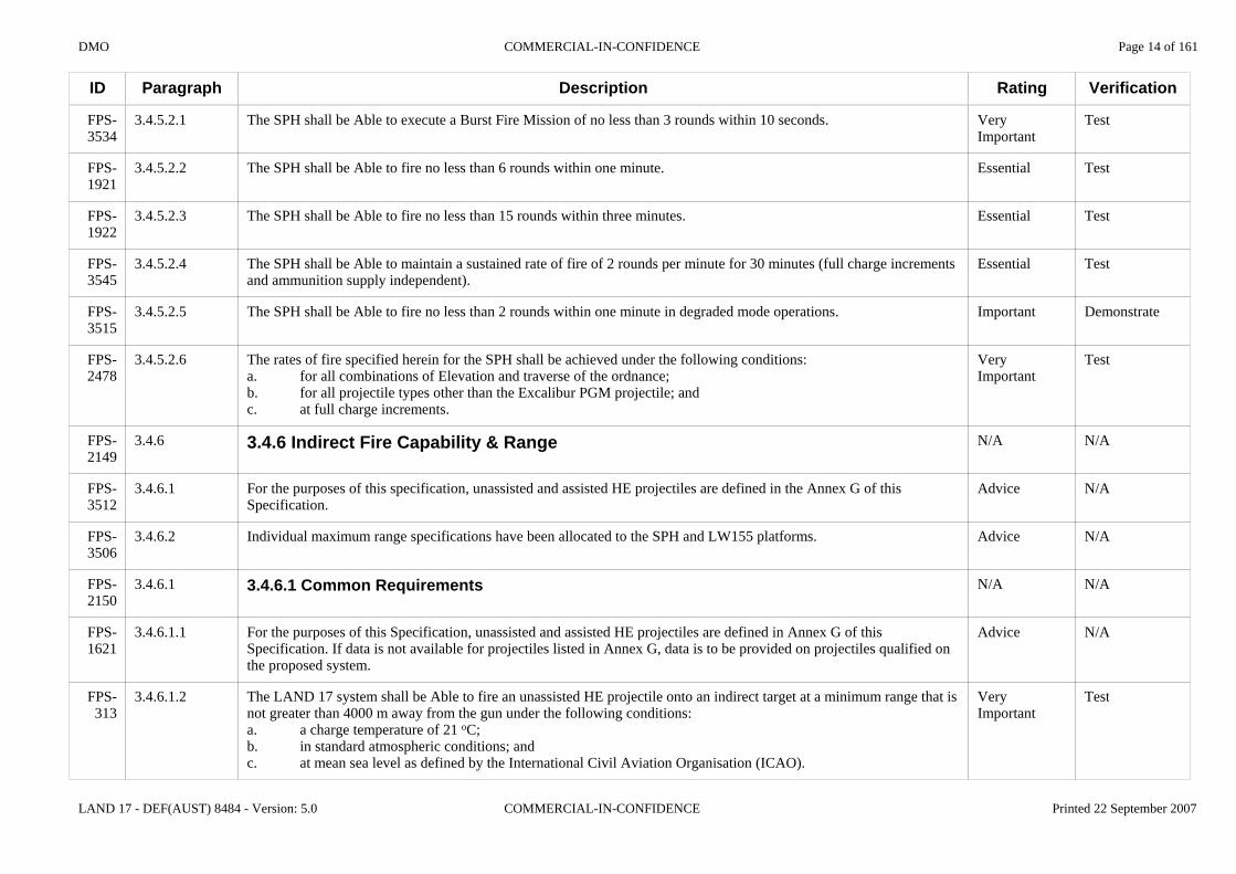
3.4.5.2.1
3.4.5.2.2
3.4.5.2.3
3.4.5.2.4
3.4.5.2.5
3.4.5.2.6
3.4.6
3.4.6.1
3.4.6.2
3.4.6.1
3.4.6.1.1
3.4.6.1.2
Description
The SPH shall be Able to execute a Burst Fire Mission of no less than 3 rounds within 10 seconds.
The SPH shall be Able to fire no less than 6 rounds within one minute.
The SPH shall be Able to fire no less than 15 rounds within three minutes.
The SPH shall be Able to maintain a sustained rate of fire of 2 rounds per minute for 30 minutes (full charge increments and ammunition supply independent).
The SPH shall be Able to fire no less than 2 rounds within one minute in degraded mode operations.
The rates of fire specified herein for the SPH shall be achieved under the following conditions:a. for all combinations of Elevation and traverse of the ordnance;b. for all projectile types other than the Excalibur PGM projectile; andc. at full charge increments.
3.4.6 Indirect Fire Capability & Range
For the purposes of this specification, unassisted and assisted HE projectiles are defined in the Annex G of this Specification.
Individual maximum range specifications have been allocated to the SPH and LW155 platforms.
3.4.6.1 Common Requirements
For the purposes of this Specification, unassisted and assisted HE projectiles are defined in Annex G of this Specification. If data is not available for projectiles listed in Annex G, data is to be provided on projectiles qualified on the proposed system.
The LAND 17 system shall be Able to fire an unassisted HE projectile onto an indirect target at a minimum range that is not greater than 4000 m away from the gun under the following conditions:a. a charge temperature of 21 oC;b. in standard atmospheric conditions; andc. at mean sea level as defined by the International Civil Aviation Organisation (ICAO).
Rating
Very Important
Essential
Essential
Essential
Important
Very Important
N/A
Advice
Advice
N/A
Advice
Very Important
Verification
Test
Test
Test
Test
Demonstrate
Test
N/A
N/A
N/A
N/A
N/A
Test

DMO COMMERCIAL-IN-CONFIDENCE Page 15 of 161
LAND 17 - DEF(AUST) 8484 - Version: 5.0 COMMERCIAL-IN-CONFIDENCE Printed 22 September 2007
ID
FPS-3507
FPS-2480
FPS-4315
FPS-2151
FPS-4316
FPS-309
FPS-3513
FPS-311
Paragraph
3.4.6.1.3
3.4.6.1.4
3.4.6.1.5
3.4.6.2
3.4.6.2.1
3.4.6.2.2
3.4.6.2.3
3.4.6.2.4
Description
The LAND 17 system shall be Able to fire an unassisted HE projectile onto an indirect target at a minimum range that is not greater than 2000 m away from the gun under the following conditions:a. a charge temperature of 21 oC;b. in standard atmospheric conditions; andc. at mean sea level as defined by the ICAO.
The LAND 17 system must be Able to safely fire an Excalibur PGM projectile onto an indirect target. Data is sought from tenderers at TDR F-18 to inform the Commonwealth's evaluation.
The detailed requirements for the delivery platform to safely fire the Excalibur PGM will be added at contract signature.
3.4.6.2 Self-Propelled Howitzer Requirements
The Commonwealth intends to procure a Modular Charge System (MCS) that has already been qualified with the SPH platform. The Essential range requirements for unassisted and assisted projectiles shall therefore be achieved utilising the supplier's offered MCSs.
The SPH shall be Able to fire an unassisted HE projectile onto an indirect target at a maximum range that is not less than 24 km away from the gun under the following conditions:a. a charge temperature of 21 oC;b. in standard atmospheric conditions; andc. at mean sea level as defined by the ICAO.
The SPH shall be Able to fire an unassisted HE projectile onto an indirect target at a maximum range that is not less than 28 km away from the gun under the following conditions:a. a charge temperature of 21 oC;b. in standard atmospheric conditions; andc. at mean sea level as defined by the ICAO.
The SPH shall be Able to fire an assisted HE projectile onto an indirect target at a maximum range that is not less than 40 km away from the gun under the following conditions:a. a charge temperature of 21 oC;b. in standard atmospheric conditions; andc. at mean sea level as defined by the ICAO.
Rating
Important
Advice
Advice
N/A
Advice
Essential
Very Important
Essential
Verification
Test
N/A
N/A
N/A
N/A
Test
N/A
Test

DMO COMMERCIAL-IN-CONFIDENCE Page 16 of 161
LAND 17 - DEF(AUST) 8484 - Version: 5.0 COMMERCIAL-IN-CONFIDENCE Printed 22 September 2007
ID
FPS-3514
FPS-314
FPS-4322
FPS-4323
FPS-4324
FPS-2153
FPS-2154
FPS-332
FPS-1512
Paragraph
3.4.6.2.5
3.4.6.2.6
3.4.6.2.7
3.4.6.2.8
3.4.6.2.9
3.4.7
3.4.7.1
3.4.7.1.1
3.4.7.1.2
Description
The SPH shall be Able to fire an assisted HE projectile onto an indirect target at a maximum range that is not less than 45 km away from the gun under the following conditions:a. a charge temperature of 21 oC;b. in standard atmospheric conditions; andc. at mean sea level as defined by the ICAO.
The SPH shall be Able to engage indirect targets between the minimum and maximum ranges without any gaps.
The SPH shall be Able to execute a Multiple Round Simultaneous Impact (MRSI) mission under the following conditions:a. not less than 5 rounds;b. at a maximum range of no less than 17 km; andc. with no more than 10 seconds lapsing between impact of the first and last projectile.
The SPH shall be Able to execute a MRSI mission under the following conditions:a. not less than 6 rounds;b. at a maximum range of no less than 17 km; andc. with no more than 10 seconds lapsing between impact of the first and last projectile.
The SPH shall be Able to execute a MRSI mission under the following conditions:a. not less than 7 rounds;b. at a maximum range of no less than 17 km; andc. with no more than 10 seconds lapsing between impact of the first and last projectile.
3.4.7 Direct Fire Capability & Range
3.4.7.1 Common Requirements
Direct fire will primarily be a defensive mode of fire, however there may be occasions, especially during complex warfighting, where offensive direct fire missions against targets will be required. Direct fire targets may include:a. infrastructure (e.g. buildings, bunkers, bridges, etc.);b. stationary vehicles (armoured and unarmoured); andc. moving targets (e.g. vehicles, personnel, vessels).
The LAND 17 system shall be fitted with a Direct Fire sighting mechanism that is Able to support the Direct Fire performance requirements stated herein, when employed during day, night and in other periods of reduced visibility.
Rating
Very Important
Very Important
Essential
Very Important
Desirable
N/A
N/A
Advice
Essential
Verification
Test
DemonstrateTest
Test
Test
Test
N/A
N/A
N/A
Demonstrate

DMO COMMERCIAL-IN-CONFIDENCE Page 17 of 161
LAND 17 - DEF(AUST) 8484 - Version: 5.0 COMMERCIAL-IN-CONFIDENCE Printed 22 September 2007
ID
FPS-1672
FPS-1673
FPS-1674
FPS-2155
FPS-333
FPS-3537
FPS-1165
FPS-3540
FPS-2379
FPS-2707
FPS-4317
Paragraph
3.4.7.1.3
3.4.7.1.4
3.4.7.1.5
3.4.7.2
3.4.7.2.1
3.4.7.2.2
3.4.7.2.3
3.4.7.2.4
3.4.7.2.5
3.4.7.2.6
3.4.7.2.7
Description
The LAND 17 system shall have an Into Action Direct Fire response time of not more than 30 seconds.
The LAND 17 system shall enable the Detachment to boresight the ordnance to within ± 0.5 mil in all workshop and field operating conditions using tools from the Standard Equipment List.
The LAND 17 system shall retain boresight to within ± 0.5 mil in all field operating conditions for a full battlefield mission.
3.4.7.2 Self-Propelled Howitzer Requirements
The SPH shall be Able to locate and engage stationary Direct Fire targets of not less than 2.5 metres square under the following conditions:a. at ranges between 200 m and 2000 m from the SPH; andb. with an arc of coverage of no less than 800 Mils left and right of the SPH chassis centre.
The SPH shall be Able to locate and engage, with at least a 60% probability of a first round hit, stationary Direct Fire targets of not less than 2.5 metres square under the following conditions:a. at ranges between 200 m and 2000 m from the SPH; andb. with an arc of coverage of no less than 800 Mils left and right of the SPH chassis centre.
The SPH shall be Able to locate and engage, with at least a 30% probability of a first round hit, moving Direct Fire targets of not less than 2.5 metres square under the following conditions:a. at ranges between 200 m and 2000 m from the SPH;b. with an arc of coverage of no less than 800 Mils left and right of the SPH chassis centre; andc. the Direct Fire target moving at crossing velocities between 1 km/h and 30 km/h.
When the SPH is operating in direct fire mode, the sighting and targeting system of the RWS shall be Able to provide targeting information to the BMS-F(FCS) and slew the main ordnance.
The SPH shall be fitted with a panoramic day and night sight with laser range finder to be utilised by the commander for the purposes of Direct Fire.
The SPH shall be fitted with a day and night sight to be utilised by the gunner for the purposes of Direct Fire.
The SPH shall be fitted with a Direct Fire engagement system that enables the main armament to be slewed automatically to the Direct Fire target observed through the commander's and gunner's day and night sights.
Rating
Important
Important
Important
N/A
Very Important
Important
Desirable
Very Important
Very Important
Very Important
Very Important
Verification
Test
Test
Test
N/A
Test
Test
Test
Test
Demonstrate
Demonstrate
Demonstrate

DMO COMMERCIAL-IN-CONFIDENCE Page 18 of 161
LAND 17 - DEF(AUST) 8484 - Version: 5.0 COMMERCIAL-IN-CONFIDENCE Printed 22 September 2007
ID
FPS-2157
FPS-2158
FPS-1667
FPS-4193
FPS-4194
FPS-4195
FPS-1669
FPS-2159
FPS-2381
FPS-2161
FPS-2162
FPS-341
FPS-343
Paragraph
3.4.8
3.4.8.1
3.4.8.1.1
3.4.8.1.1.1
3.4.8.1.1.2
3.4.8.1.1.3
3.4.8.1.2
3.4.8.2
3.4.8.2.1
3.4.9
3.4.9.1
3.4.9.1.1
3.4.9.1.2
Description
3.4.8 Terrain
3.4.8.1 Common Requirements
The LAND 17 system shall be Able to meet all functional and performance requirements when operated in complex terrain including:
a. urban terrain;
b. forested terrain; and
c. hilly/mountainous terrain.
The LAND 17 system shall be Able to meet all functional and performance requirements when operated on cants and pitches up to and including 10 degrees on all terrain types.
3.4.8.2 Self-Propelled Howitzer Requirements
Not used.
3.4.9 Survey System
3.4.9.1 Common Requirements
The LAND 17 survey system is the integrated orientation/location-fixing system that provides timely and accurate positional data to the LAND 17 platform Fire Control System (FCS). The orientation/location system will include all equipment and components necessary for this task (e.g. global positioning system (GPS) receiver, inertial navigation system (INS) equipment, etc.).
The LAND 17 survey system shall be an integrated orientation and location fixing system that is integrated with the BMS-F(FCS) equipment on every LAND 17 weapon platform.
Rating
N/A
N/A
Very Important
Very Important
Very Important
Very Important
Very Important
N/A
Advice
N/A
N/A
Advice
Essential
Verification
N/A
N/A
Demonstrate
DemonstrateConformance Statement
Conformance Statement
DemonstrateConformance Statement
Demonstrate
N/A
N/A
N/A
N/A
N/A
Inspect
DMO COMMERCIAL-IN-CONFIDENCE Page 19 of 161
LAND 17 - DEF(AUST) 8484 - Version: 5.0 COMMERCIAL-IN-CONFIDENCE Printed 22 September 2007
ID
FPS-1946
FPS-344
FPS-362
FPS-363
FPS-1930
FPS-4196
FPS-4197
FPS-4198
FPS-364
FPS-4199
FPS-4200
FPS-4201
FPS-366
FPS-367
Paragraph
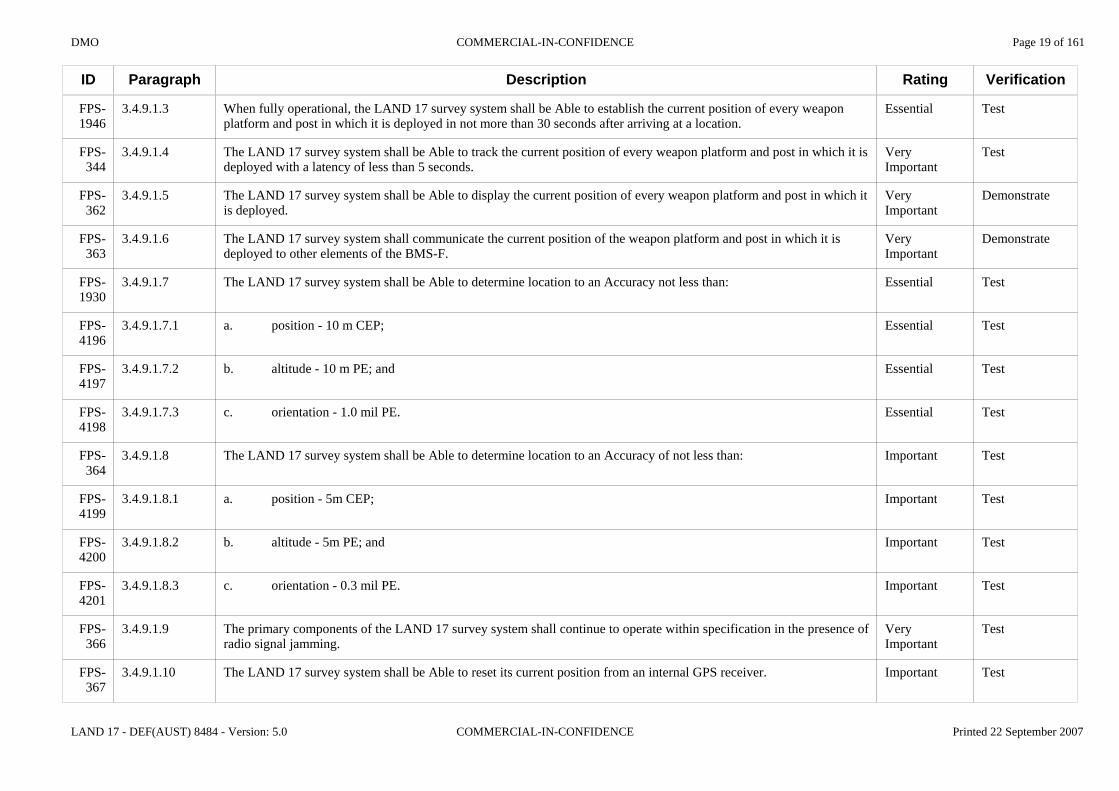
3.4.9.1.3
3.4.9.1.4
3.4.9.1.5
3.4.9.1.6
3.4.9.1.7
3.4.9.1.7.1
3.4.9.1.7.2
3.4.9.1.7.3
3.4.9.1.8
3.4.9.1.8.1
3.4.9.1.8.2
3.4.9.1.8.3
3.4.9.1.9
3.4.9.1.10
Description
When fully operational, the LAND 17 survey system shall be Able to establish the current position of every weapon platform and post in which it is deployed in not more than 30 seconds after arriving at a location.
The LAND 17 survey system shall be Able to track the current position of every weapon platform and post in which it is deployed with a latency of less than 5 seconds.
The LAND 17 survey system shall be Able to display the current position of every weapon platform and post in which it is deployed.
The LAND 17 survey system shall communicate the current position of the weapon platform and post in which it is deployed to other elements of the BMS-F.
The LAND 17 survey system shall be Able to determine location to an Accuracy not less than:
a. position - 10 m CEP;
b. altitude - 10 m PE; and
c. orientation - 1.0 mil PE.
The LAND 17 survey system shall be Able to determine location to an Accuracy of not less than:
a. position - 5m CEP;
b. altitude - 5m PE; and
c. orientation - 0.3 mil PE.
The primary components of the LAND 17 survey system shall continue to operate within specification in the presence of radio signal jamming.
The LAND 17 survey system shall be Able to reset its current position from an internal GPS receiver.
Rating
Essential
Very Important
Very Important
Very Important
Essential
Essential
Essential
Essential
Important
Important
Important
Important
Very Important
Important
Verification
Test
Test
Demonstrate
Demonstrate
Test
Test
Test
Test
Test
Test
Test
Test
Test
Test
DMO COMMERCIAL-IN-CONFIDENCE Page 20 of 161
LAND 17 - DEF(AUST) 8484 - Version: 5.0 COMMERCIAL-IN-CONFIDENCE Printed 22 September 2007
ID
FPS-1166
FPS-368
FPS-369
FPS-4202
FPS-4203
FPS-4204
FPS-4205
FPS-4206
FPS-4207
FPS-4208
FPS-4209
FPS-4210
FPS-370
FPS-371
Paragraph
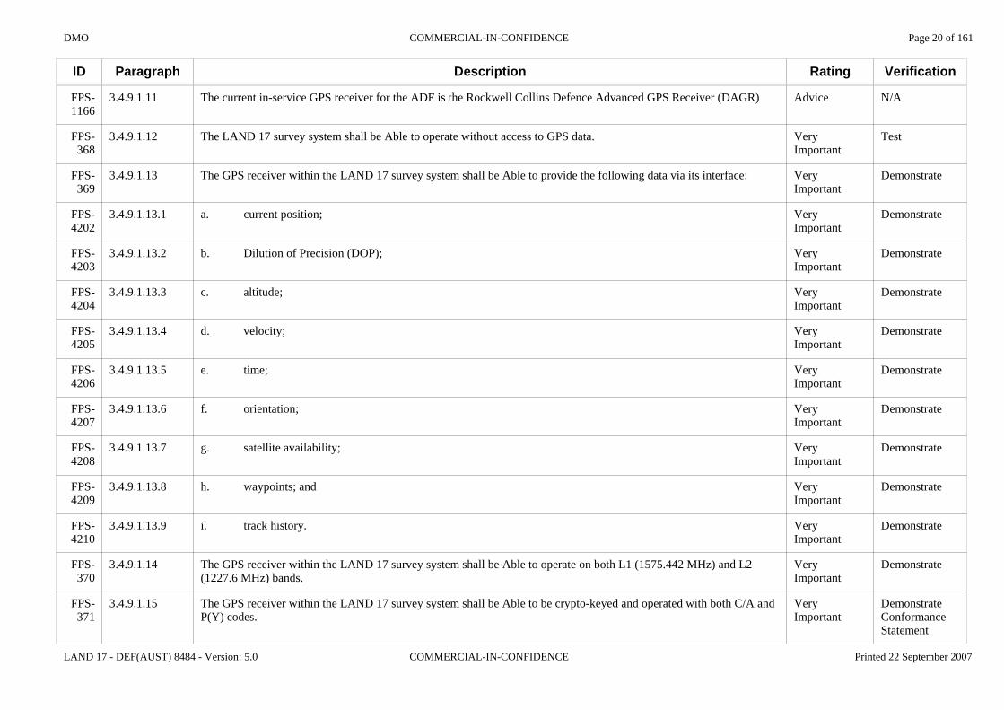
3.4.9.1.11
3.4.9.1.12
3.4.9.1.13
3.4.9.1.13.1
3.4.9.1.13.2
3.4.9.1.13.3
3.4.9.1.13.4
3.4.9.1.13.5
3.4.9.1.13.6
3.4.9.1.13.7
3.4.9.1.13.8
3.4.9.1.13.9
3.4.9.1.14
3.4.9.1.15
Description
The current in-service GPS receiver for the ADF is the Rockwell Collins Defence Advanced GPS Receiver (DAGR)
The LAND 17 survey system shall be Able to operate without access to GPS data.
The GPS receiver within the LAND 17 survey system shall be Able to provide the following data via its interface:
a. current position;
b. Dilution of Precision (DOP);
c. altitude;
d. velocity;
e. time;
f. orientation;
g. satellite availability;
h. waypoints; and
i. track history.
The GPS receiver within the LAND 17 survey system shall be Able to operate on both L1 (1575.442 MHz) and L2 (1227.6 MHz) bands.
The GPS receiver within the LAND 17 survey system shall be Able to be crypto-keyed and operated with both C/A and P(Y) codes.
Rating
Advice
Very Important
Very Important
Very Important
Very Important
Very Important
Very Important
Very Important
Very Important
Very Important
Very Important
Very Important
Very Important
Very Important
Verification
N/A
Test
Demonstrate
Demonstrate
Demonstrate
Demonstrate
Demonstrate
Demonstrate
Demonstrate
Demonstrate
Demonstrate
Demonstrate
Demonstrate
DemonstrateConformance Statement

DMO COMMERCIAL-IN-CONFIDENCE Page 21 of 161
LAND 17 - DEF(AUST) 8484 - Version: 5.0 COMMERCIAL-IN-CONFIDENCE Printed 22 September 2007
ID
FPS-2307
FPS-849
FPS-372
FPS-373
FPS-374
FPS-850
FPS-376
FPS-2163
FPS-2383
FPS-2476
FPS-2477
FPS-2165
Paragraph
3.4.9.1.16
3.4.9.1.17
3.4.9.1.18
3.4.9.1.19
3.4.9.1.20
3.4.9.1.21
3.4.9.1.22
3.4.9.2
3.4.9.2.1
3.4.9.2.2
3.4.9.2.3
3.4.10
Description
The GPS receiver within the LAND 17 survey system shall be Able to be crypto-keyed and operated with M code.
The crypto-key data for the GPS receiver shall be Able to be zeroed or deleted.
The GPS receiver within the LAND 17 survey system shall be a SA-ASM type device.
The GPS receiver within the LAND 17 survey system shall be GPS Receiver Application Module (GRAM) based to provide easy future upgradeability.
The GPS receiver within the LAND 17 survey system shall have anti-jam properties Able to provide up to 55dB of protection against intentional and non-intentional interference.
In normal operation, the BMS-F(FCS) shall automatically read location and navigation data from the LAND 17 survey system.
In the event of a Failure of the LAND 17 survey system the Operator shall be Able to manually enter location data into the BMS-(FCS).
3.4.9.2 Self-Propelled Howitzer Requirements
A fully operational SPH shall be Able to provide location and orientation data to another SPH which:a. is located within 500m of the fully operational SPH; andb. has lost its own position/orientation data.
The transfer of survey data between adjacent platforms shall not:a. take longer than two minutes; andb. require any member of either Detachment to leave their position.
The loss of firing Accuracy of the receiving LAND 17 platform shall not exceed 10%.
3.4.10 Munitions
Rating
Important
Very Important
Very Important
Important
Important
Very Important
Very Important
N/A
Important
Important
Important
N/A
Verification
DemonstrateConformance Statement
Inspect
InspectConformance Statement
InspectConformance Statement
Test
Demonstrate
Demonstrate
N/A
Demonstrate
Demonstrate
Demonstrate
N/A

DMO COMMERCIAL-IN-CONFIDENCE Page 22 of 161
LAND 17 - DEF(AUST) 8484 - Version: 5.0 COMMERCIAL-IN-CONFIDENCE Printed 22 September 2007
ID
FPS-4310
FPS-2166
FPS-851
FPS-378
FPS-377
FPS-694
FPS-3509
FPS-379
FPS-4211
FPS-4212
Paragraph
3.4.10.1
3.4.10.1
3.4.10.1.1
3.4.10.1.2
3.4.10.1.3
3.4.10.1.4
3.4.10.1.5
3.4.10.1.6
3.4.10.1.6.1
3.4.10.1.6.2
Description
The term munitions refers to projectiles, charge systems (both bag and modular) and fuses.
3.4.10.1 Common Requirements
Suppliers should be aware of the Medium Artillery Replacement Ammunition Project (MARAP) and its role in selecting a new family of 155mm munitions for the M198 howitzer. By the time LAND 17 is delivered, MARAP is likely to be in-service. Current in-service munitions are listed in Annex F of this Specification.
The LAND 17 system should be compliant with DEF(AUST) 8416. For the purposes of this Specification the following definitions apply:a. Interchangeability Ammunition interchangeability is achieved when weapon and ammunition systems are designed so that any mixture of projectile, propelling charge and igniter tube can be fired safely and effectively from any gun or howitzer, using the firing data developed for the agreed families of projectiles.b. Ballistic Similitude Two types of projectiles with the appropriate fuse are ballistically similar if their external shape, mass, centre of gravity, transverse and longitudinal moments of inertia, surface finish and driving band characteristics are sufficiently close to ensure that their mean points of impact do not differ by more than one Probable Error (PE) in range and one PE in deflection after the application, for each propellant zone (charge), of a constant correction to Muzzle Velocity (MV) and/or air density for range and a constant angular or percentage correction for deflection.
The LAND 17 system shall be Able to Accurately fire all in-service, unguided 155mm ADF munitions as defined in Annex F of this Specification.
The LAND 17 system shall be Able to Accurately fire Artillery Delivered High Precision Munitions (ADHPM) as defined in Annex G of this Specification.
The LAND 17 system shall be Able to Accurately fire all DEF(AUST) 8416 compliant ammunition and associated charges over the full range of elevations and traverse.
The types of fuses that the LAND 17 system shall be Able to use include the following:
a. Point Detonating (PD);
b. Delay;
Rating
Advice
N/A
Advice
Advice
Essential
Essential
Very Important
Very Important
Very Important
Very Important
Verification
N/A
N/A
N/A
N/A
Test
Test
Demonstrate
Demonstrate
Demonstrate
Demonstrate

DMO COMMERCIAL-IN-CONFIDENCE Page 23 of 161
LAND 17 - DEF(AUST) 8484 - Version: 5.0 COMMERCIAL-IN-CONFIDENCE Printed 22 September 2007
ID
FPS-4213
FPS-4214
FPS-4215
FPS-4216
FPS-1514
FPS-1644
FPS-2167
FPS-3473
FPS-4331
FPS-3476
FPS-4294
FPS-4293
FPS-2169
Paragraph
3.4.10.1.6.3
3.4.10.1.6.4
3.4.10.1.6.5
3.4.10.1.6.6
3.4.10.1.7
3.4.10.1.8
3.4.10.2
3.4.10.2.1
3.4.10.2.2
3.4.10.2.3
3.4.10.2.4
3.4.10.2.5
3.4.11
Description
c. Electronic time;
d. Trajectory correcting;
e. Proximity; and
f. Multifunction.
The LAND 17 system shall be Able to use all fuses that are compliant with Sections 5 and 6 of DEF(AUST) 8416.
The LAND 17 system shall be Able to use ammunition and charges that are compliant with the Insensitive Munitions (IM) requirements of STANAG 4439, as directed by Defence Instruction DI(G) LOG 07-10.
3.4.10.2 Self-Propelled Howitzer Requirements
The SPH shall be Able to Accurately fire, over the full range of Elevations and traverse, all projectiles with Ballistic Similitude to the reference projectiles as defined in Section 4.4 of DEF(AUST) 8416.
The SPH MCS shall be compliant with the Insensitive Munitions (IM) requirements of STANAG 4439, as directed by DI(G) LOG 07-10.
The SPH shall be Able to use all charge systems that comply with the dimensional and pressure constraints described in Section 4.3 of DEF(AUST) 8416.
The SPH when firing the MCS shall be fully functional and safe to operate for MCS temperatures in the range of -46 oC to 63 oC.
The SPH MCS shall be safe for handling, transporting and storage in the temperature range from -51 oC to 71 oC.
3.4.11 Battle Management System - Fires
Rating
Very Important
Very Important
Very Important
Very Important
Important
Very Important
N/A
Very Important
Very Important
Very Important
Very Important
Very Important
N/A
Verification
Demonstrate
Demonstrate
Demonstrate
Demonstrate
Conformance Statement
DemonstrateConformance Statement
N/A
DemonstrateConformance Statement
Conformance Statement
DemonstrateConformance Statement
Test
Test
N/A

DMO COMMERCIAL-IN-CONFIDENCE Page 24 of 161
LAND 17 - DEF(AUST) 8484 - Version: 5.0 COMMERCIAL-IN-CONFIDENCE Printed 22 September 2007
ID
FPS-3595
FPS-3596
FPS-3597
FPS-2170
FPS-3598
FPS-1168
FPS-1169
FPS-1170
FPS-1171
FPS-3599
Paragraph
3.4.11.1
3.4.11.1.1
3.4.11.1.2
3.4.11.2
3.4.11.2.1
3.4.11.2.1-1
3.4.11.2.1-2
3.4.11.2.1-3
3.4.11.2.1-4
3.4.11.2.1-5
Description
3.4.11.1 Background
The LAND 17 BMS-F consists of three sub-systems that provide integrated SA, C2, mission planning and fire coordination of Joint and Coalition fires.
The BMS-F section of this document is divided into BMS-F Common Requirements and requirements specific to each BMS-F sub-system. Tenderers are provided with the specific information necessary to compile responses plus additional information as ADVICE clauses for completeness. Some redundant headings are provided for continuity.
3.4.11.2 Battle Management System Common Requirements
3.4.11.2.1 General
The LAND 17 BMS-F will be deployed as appropriate across JOSCCs, Fire Direction Centres (FDCs), Forward Observer (FO) locations and gun platforms. The BMS-F comprises the following components:a. BMS-F(C2): JOSCCs and FDCs; b. BMS-F(FO): FO and Terminal Attack Controllers; andc. BMS-F(FCS): SPH and LW155 platforms.
For the purposes of this section of the specification, the term BMS-F will be construed to include the BMS-F(C2), BMS-F(FO) and BMS-F(FCS). The definition includes all the hardware, software, communication interfaces, sub-system interfaces, ancillaries, installation kits and any other components required to achieve the stated requirements.
All requirements in the BMS-F section of this document are to be read as applying to all components of the BMS-F unless otherwise stated.
The BMS-F shall perform the following functions:a. user management;b. preparation of fire plans;c. management of joint and coalition fires;d. management of reports & returns;e. communications with external systems and units;f. event logging;g. management of geospatial data / digital maps; andh. Excalibur specific mission planning and technical fire direction.
The BMS-F shall display all text in English.
Rating
N/A
Advice
Advice
Advice
N/A
Advice
Advice
Advice
Essential
Very Important
Verification
N/A
N/A
N/A
N/A
N/A
N/A
N/A
N/A
Test
Demonstrate

DMO COMMERCIAL-IN-CONFIDENCE Page 25 of 161
LAND 17 - DEF(AUST) 8484 - Version: 5.0 COMMERCIAL-IN-CONFIDENCE Printed 22 September 2007
ID
FPS-3600
FPS-1172
FPS-1185
FPS-1179
FPS-1180
FPS-1181
FPS-1802
FPS-1803
FPS-1183
FPS-1184
FPS-1800
Paragraph
3.4.11.2.1-6
3.4.11.2.2
3.4.11.2.2.1
3.4.11.2.2.2
3.4.11.2.2.3
3.4.11.2.2.4
3.4.11.2.2.5
3.4.11.2.2.6
3.4.11.2.2.7
3.4.11.2.2.8
3.4.11.2.2.9
Description
The BMS-F software applications shall be capable of operating on a commercially available multitasking operating system.
3.4.11.2.2 Log File
The BMS-F will include a system log to record significant events and reports as entries within a single repository. These log entries are regarded as a permanent record of the events of an operation as they unfold and need to be auditable. Recorded in the log will be events such as messages sent or received from CNR or LAN, manually entered orders, and actions performed by the BMS-F.
The BMS-F shall have an event logging capability.
The event logging capability shall be present and active in every operating computer within the BMS-F, whenever the BMS-F software is active.
The event logging capability on each operating computer within the BMS-F shall record data in a single BMS-F log file on that computer.
Each entry in the BMS-F log file shall be:a. time & date stamped; andb. contain sufficient detail to provide a usable audit record of the activity that was logged.
The events captured by the logging capability shall include:a. messages of all types sent or received by the BMS-F; andb. all activities carried out by the BMS-F.
The BMS-F shall enable a user to:a. export all the existing BMS-F log entries; andb. export a user defined selection of BMS-F log entries.
The BMS-F log entries shall be Able to be exported in the following formats:a. a plain text file; andb. a plain text Comma Separated Variable (CSV) file.
The BMS-F shall enable a user to backup or duplicate the log file to an alternate data storage device including:a. a 3.5in floppy disk;b. an alternate hard disk;c. an optical disk; andd. an USB data device.
Rating
Important
N/A
Advice
Very Important
Very Important
Very Important
Very Important
Very Important
Very Important
Important
Very Important
Verification
Demonstrate
N/A
N/A
Demonstrate
Demonstrate
Demonstrate
Inspect
Demonstrate
Demonstrate
Demonstrate
Demonstrate

DMO COMMERCIAL-IN-CONFIDENCE Page 26 of 161
LAND 17 - DEF(AUST) 8484 - Version: 5.0 COMMERCIAL-IN-CONFIDENCE Printed 22 September 2007
ID
FPS-1821
FPS-1186
FPS-1187
FPS-1791
FPS-1188
FPS-1189
FPS-1793
FPS-1794
FPS-1792
FPS-1190
FPS-1276
FPS-1277
Paragraph
3.4.11.2.2.10
3.4.11.2.3
3.4.11.2.3.1
3.4.11.2.3.2
3.4.11.2.3.3
3.4.11.2.3.4
3.4.11.2.3.5
3.4.11.2.3.6
3.4.11.2.3.7
3.4.11.2.3.8
3.4.11.2.3.9
3.4.11.2.3.10
Description
The BMS-F shall provide a means for an authorised user to erase the current log file contents.
3.4.11.2.3 Geospatial Data, Display & Analysis
The BMS-F should be Capable of displaying and working from an electronic map. The basis of the map data will be military geospatial data supplied by Commonwealth and allied agencies.
The Defence Information Management Policy Instruction (DIMPI) 15/2000 details the Common Operating Environment (COE) for Defence Geospatial Information Systems (GIS). This COE is based on the ESRI and Leica ERDAS software and is used to produce ADF geospatial products.
The BMS-F shall be Able to display a digital map.
The BMS-F digital map shall be based on geospatial data that meets at least one or more of the standards as defined in Annex A of the DI(G) OPS 20-3.
The BMS-F shall be Able to import geospatial data of the following types:a. CADRG (MIL-PRF-89038, Amendment 2);b. Digital Terrain Elevation Data Levels 0, 1 & 2 (MIL-PRF-89020B);c. VMAP Level 1 (MIL-PRF-89033) (Scale 1:250,000); andd. VMAP Level 2 (MIL-PRF-89032) (Scale 1:50,000).
The horizontal datum for geospatial data shall be WGS 84.
The vertical datum for geospatial data shall be:a. Australian Height Datum (AHD) for all Australian data; andb. Mean Sea Level (MSL) at defined points for data of non-Australian origin.
Where a digital map is not present, the BMS-F shall present a blank map display with the Universal Transverse Mercator (UTM) grid markings for the current area of interest overlayed.
The BMS-F shall support the following geographic projections:a. Transverse Mercator; andb. Mercator
The default parameters for the Transverse Mercator projection shall be the UTM set.
Rating
Important
N/A
Advice
Advice
Essential
Very Important
Very Important
Very Important
Very Important
Essential
Important
Important
Verification
Demonstrate
N/A
N/A
N/A
Demonstrate
Inspect
Test
Inspect
Inspect
Demonstrate
Demonstrate
Inspect

DMO COMMERCIAL-IN-CONFIDENCE Page 27 of 161
LAND 17 - DEF(AUST) 8484 - Version: 5.0 COMMERCIAL-IN-CONFIDENCE Printed 22 September 2007
ID
FPS-1278
FPS-1191
FPS-1192
FPS-1206
FPS-1193
FPS-1195
FPS-1197
FPS-1198
FPS-1200
FPS-1201
FPS-1202
FPS-1204
Paragraph
3.4.11.2.3.11
3.4.11.2.3.12
3.4.11.2.3.13
3.4.11.2.3.14
3.4.11.2.3.15
3.4.11.2.3.16
3.4.11.2.3.17
3.4.11.2.3.18
3.4.11.2.3.19
3.4.11.2.3.20
3.4.11.2.3.21
3.4.11.2.3.22
Description
WGS 84 datum lat/long coordinate conversion to or from other coordinate systems shall use the algorithms found in MIL-STD-2401.
The system is to provide functionality which enables users to access specialist tools for Geospatial Information Software analysis. The specialist tools should be accessible only if a foundation overlay containing Digital Terrain Elevation Data (DTED) for the area of operations is installed on the system. The fidelity of the analysis outcomes will be constrained by the fidelity of the DTED. The specialist tools should include Crest analysis and line-of-sight analysis.
The BMS-F shall provide the following types of geospatial analysis tools:a. line of sight analysis; andb. near and far Crest analysis.
The BMS-F line of sight analysis tool shall be Able to create a line of sight profile between any two points selected by the user on the map display.
The BMS-F shall be Able to display to the user the distance between two points over one or more line segments on a map.
The BMS-F shall be Able to display to the user the Bearing from one point on the map display to another point on the map display.
The BMS-F shall be Able to display to the user the Bearing and distance of a point on the map display relative to another point on the map display.
Where a foundation overlay containing DTED is present, all Bearings shall include both Azimuth and altitude from the initial point to the point specified by the user.
The BMS-F shall be Able to identify Crests as either occupied or unoccupied by friendly forces.
The BMS-F shall provide a facility for an authorised user to modify the default clearances for occupied and unoccupied Crests.
The BMS-F shall allow the user to enter point Crest data for those situations where a foundation overlay containing DTED is not present.
Point Crest locations shall be defined by the BMS-F as either:a. a single point (grid co-ordinates and altitude); orb. a multi-segment line (polyline) with a minimum of four definition points (grid co-ordinates and altitude).
Rating
Important
Advice
Important
Important
Important
Important
Important
Important
Very Important
Important
Very Important
Very Important
Verification
Conformance Statement
N/A
Demonstrate
Demonstrate
Demonstrate
Demonstrate
Demonstrate
Demonstrate
Demonstrate
Demonstrate
Demonstrate
Demonstrate

DMO COMMERCIAL-IN-CONFIDENCE Page 28 of 161
LAND 17 - DEF(AUST) 8484 - Version: 5.0 COMMERCIAL-IN-CONFIDENCE Printed 22 September 2007
ID
FPS-1824
FPS-1203
FPS-1822
FPS-1207
FPS-1194
FPS-1795
FPS-1289
FPS-1290
FPS-1209
FPS-1275
FPS-1468
Paragraph
3.4.11.2.3.23
3.4.11.2.3.24
3.4.11.2.3.25
3.4.11.2.3.26
3.4.11.2.3.27
3.4.11.2.3.28
3.4.11.2.3.29
3.4.11.2.3.30
3.4.11.2.3.31
3.4.11.2.3.32
3.4.11.2.3.33
Description
The BMS-F shall store the following data for each point Crest:a. point Crest location; andb. occupied/unoccupied status.
The BMS-F shall be Able to store a maximum of not less than 50 user entered point Crests.
The BMS-F shall be Able to display on the map all stored point Crests including a visual indication of occupied/unoccupied status.
In addition to the geospatial analysis tools, there should also be a tool for the graphical and non-graphical creation and management of areas of interest such as fire and no-fire zones, air corridors (fire coordination support measures), etc.
The BMS-F shall provide the user with tools to graphically create, modify, store and delete areas of interest on an overlay to the map display.
The BMS-F shall provide the user with a tool to create and manage areas of interest on an overlay to the map display by the manual entry and editing of grid co-ordinates representing the vertices of the areas of interest.
The BMS-F is required to be Able to uniquely identify enemy, unknown and friendly units. Unit identification allows users to participate in situational awareness activities, messaging, planning, mission execution, and capability status. The system should also have a unit/formation editor that creates data and symbology in accordance with MIL-STD-2525BCN2.
The BMS-F shall provide a tool for the user to create, modify and delete identities on an active overlay for:a. enemy units;b. friendly units; and c. other units (including neutral, suspect, hostile, unknown, joker and faker).
The BMS-F shall provide a unit/formation editor that allows a user to add data and symbology in accordance with MIL-STD-2525BCN2 for display on a map overlay.
The BMS-F shall permit geospatial data entry in the following coordinate systems:a. UTM Grid Coordinates (zone, eastings, northings, altitude); andb. polar coordinates (Bearing, range and Angle of Sight).
The BMS-F shall also permit geospatial data entry in geographic coordinates (lat/long, altitude).
Rating
Very Important
Important
Important
Advice
Important
Important
Advice
Very Important
Important
Very Important
Very Important
Verification
Demonstrate
Demonstrate
Demonstrate
N/A
Demonstrate
Demonstrate
N/A
Demonstrate
Demonstrate
Demonstrate
Demonstrate

DMO COMMERCIAL-IN-CONFIDENCE Page 29 of 161
LAND 17 - DEF(AUST) 8484 - Version: 5.0 COMMERCIAL-IN-CONFIDENCE Printed 22 September 2007
ID
FPS-1319
FPS-1316
FPS-1317
FPS-1804
FPS-3602
FPS-1318
FPS-1320
FPS-1322
FPS-1323
FPS-1324
Paragraph
3.4.11.2.3.34
3.4.11.2.4
3.4.11.2.4.1
3.4.11.2.4.2
3.4.11.2.4.3
3.4.11.2.4.4
3.4.11.2.5
3.4.11.2.5.1
3.4.11.2.5.2
3.4.11.2.5.3
Description
The BMS-F shall be Able to process spatial data within the limits of the UTM projection latitude extents:a. within the Northern Hemisphere from 0 degrees to 84 Degrees North;b. within the Southern Hemisphere from 0 degrees to 80 Degrees South; andc. straddling the equator.
3.4.11.2.4 Data Assurance
On powering up the BMS-F shall always be initialised to a Safe State.
A "Safe State" is defined as being one where the BMS-F application software (either in whole or in part if modular) is loaded into memory, the application has initialised and is waiting for user input at a defined point. The software initialisation was based on the inherent and user-defined default settings that are stored within the application. The application cannot proceed without additional user input.
The BMS-F Operating System shall incorporate protection against virus attack.
In order to minimise data corruption the BMS-F shall use an error detection/correction method for all data transferred within the BMS-F network.
3.4.11.2.5 Built-In Testing
The LAND 17 system shall provide built-in tests (BIT) and diagnostics for both hardware and software including:a. power-on BIT during system start up;b. continuous BIT during operation; andc. Operator initiated BIT at any time the system is turned on.
Power-on BIT shall include:a. standard power-on self-test on all computers;b. testing of the network state of the BMS-F during system start-up;c. testing of the weapon platform systems during system start-up (applicable to BMS-F(FCS) only); andd. user notification of all faults or failures.
Continuous BIT shall include:a. monitoring of the status of each subsystem of the BMS-F during normal operation;b. detection and reporting of any faults, failures or incidents within the BMS-F during normal operation; andc. user notification of all faults or failures.
Rating
Very Important
N/A
Essential
Advice
Very Important
Very Important
N/A
Very Important
Important
Important
Verification
Demonstrate
N/A
Inspect
N/A
Demonstrate
TestInspect
N/A
Demonstrate
Demonstrate
Demonstrate

DMO COMMERCIAL-IN-CONFIDENCE Page 30 of 161
LAND 17 - DEF(AUST) 8484 - Version: 5.0 COMMERCIAL-IN-CONFIDENCE Printed 22 September 2007
ID
FPS-1325
FPS-3603
FPS-1173
FPS-1210
FPS-1211
FPS-1212
FPS-3604
FPS-1213
FPS-1174
Paragraph
3.4.11.2.5.4
3.4.11.2.5.5
3.4.11.2.6
3.4.11.2.6.1
3.4.11.2.6.2
3.4.11.2.6.3
3.4.11.2.6.4
3.4.11.2.6.5
3.4.11.2.7
Description
Operator initiated BIT shall include:a. user selected test options;b. individual testing of each system element;c. batch testing of system elements;d. ability for the user to abort current test(s); ande. user notification of all faults or failures.
The BMS-F shall have a log record of all BIT failures identified.
3.4.11.2.6 User Management
The BMS-F is required to support users with varying levels of system access. Access levels may be role-based (e.g. FO, Regimental or Battery FDC, gun platform, Battle Group JOSCC etc.), or they may be system-based (i.e. uniquely name based with associated group privileges such as limited user, unlimited user, administrator, etc.).
The BMS-F shall have a built-in mechanism for managing users and their access to BMS-F data and applications.
The BMS-F shall provide different levels of user access to BMS-F data and applications.
The BMS-F shall provide different rights for users at each level of access to BMS-F data and applications.
The BMS-F shall provide a facility for a user to enter identifying data about the user's own unit.
3.4.11.2.7 Preparation of Fire Plans
Rating
Important
Important
N/A
Advice
Very Important
Very Important
Desirable
Very Important
N/A
Verification
Demonstrate
Demonstrate
N/A
N/A
Demonstrate
Demonstrate
Demonstrate
Demonstrate
N/A

DMO COMMERCIAL-IN-CONFIDENCE Page 31 of 161
LAND 17 - DEF(AUST) 8484 - Version: 5.0 COMMERCIAL-IN-CONFIDENCE Printed 22 September 2007
ID
FPS-1218
FPS-1224
FPS-1231
FPS-1807
FPS-1220
FPS-1221
FPS-1219
FPS-1232
FPS-1279
FPS-1175
Paragraph
3.4.11.2.7.1
3.4.11.2.7.2
3.4.11.2.7.3
3.4.11.2.7.4
3.4.11.2.7.5
3.4.11.2.7.6
3.4.11.2.7.7
3.4.11.2.7.8
3.4.11.2.7.9
3.4.11.2.8
Description
The BMS-F FPs shall include the following information:a. Target identification number(s);b. Target Description(s);c. Target location(s);d. Remarks;e. H-hour;f. Time on Target (TOT) and duration;g. Type(s) of ammunition and fuse;h. Fire Unit Identifier; andi. Method of Fire For Effect (FFE).
A major part of fire planning is target management and the BMS-F will provide users with the ability to create, store and manage target lists for use in Fire Plans and Fire Missions.
Target identification for artillery will consist of the letters (V[S-U]) and a four digit number in the range 0001-9999. For mortars, the identification will be the single letter M followed by a four digit number in the range 0001-9999.
The BMS-F target record shall contain the following minimum information:a. Target identification label (six alphanumeric characters);b. Target location; andc. Target priority.
The BMS-F shall be Able to accept the entry and editing of target locations in:a. grid co-ordinates (zone, easting, northing, and altitude); andb. polar notation (Bearing, range & Angle of Sight (Up/Down) from a defined/known location).
The BMS-F shall be Able to accept the entry and editing of target locations in geographic co-ordinates (Lat/Long and altitude).
For each FP the BMS-F shall be Capable of storing a maximum of not less than 20 target records.
The BMS-F shall be Able to import and export target lists from external sources.
The BMS-F shall receive and be Able to accept target information from:a. manual target data entry; andb. Variable Message Format (VMF) message.
3.4.11.2.8 Management of Fire Missions
Rating
Important
Advice
Advice
Very Important
Very Important
Very Important
Important
Very Important
Very Important
N/A
Verification
Demonstrate
N/A
N/A
Demonstrate
Demonstrate
Demonstrate
Demonstrate
Demonstrate
Demonstrate
N/A

DMO COMMERCIAL-IN-CONFIDENCE Page 32 of 161
LAND 17 - DEF(AUST) 8484 - Version: 5.0 COMMERCIAL-IN-CONFIDENCE Printed 22 September 2007
ID
FPS-2120
FPS-1274
FPS-1233
FPS-1474
FPS-1263
FPS-1259
FPS-1266
FPS-1808
FPS-1270
…
Paragraph
3.4.11.2.8.1
3.4.11.2.8.1.1
3.4.11.2.8.2
3.4.11.2.8.2.1
3.4.11.2.8.2.2
3.4.11.2.8.2.3
3.4.11.2.8.2.4
3.4.11.2.8.2.5
3.4.11.2.8.2.6
Description
3.4.11.2.8.1 General
The BMS-F shall be Able to support all of the types of fire mission listed below:a. Neutralisation,b. Multiple Fire Unit Missions;c. High Explosive Air Burst Missions;d. Linear and Area Missions;e. Moving Target Missions;f. Artillery Danger Close Missions;g. Smoke Missions;h. Quick Smoke Missions;i. Deliberate Smoke Missions;j. Destruction Missions (utilising conventional HE munitions);k. Destruction Missions (utilising Excalibur);l. Destruction Missions (utilising Sensor Fused Munitions);m. Coordinated High Explosive Illuminating Missions;n. Continuous Illuminating Missions;o. Radar Adjustment Missions; p. Miscellaneous Procedures; andq. Multiple Round Simultaneous Impact.
3.4.11.2.8.2 Fire Mission Profiles
Fire Mission Profiles (FMP) contain the target and mission details for a single fire mission as passed on by the BMS-F(C2) or BMS-F(FO). The Fire Mission Profile on the BMS-F(FCS) will also include the calculated Fire Solution for that gun.
The BMS-F shall include a fire mission planning tool for an authorised user to create, store, modify and delete FMP.
The BMS-F shall require the user to confirm or cancel the entry or modification of fire mission data before it is accepted by the system.
The BMS-F shall allow an authorised user to enter an alphanumeric text label for each of the stored FMP.
The alphanumeric text label for each of the stored FMP within the BMS-F shall have a maximum length of not less than seven characters.
The display of tactical situational awareness on a digital map of the BMS-F shall include the following functions:a. disposition of forces;b. way points;
Rating
N/A
Very Important
N/A
Advice
Very Important
Important
Important
Important
Very Important
Verification
N/A
DemonstrateConformance Statement
N/A
N/A
Demonstrate
Demonstrate
Demonstrate
Demonstrate
Demonstrate
DMO COMMERCIAL-IN-CONFIDENCE Page 33 of 161
LAND 17 - DEF(AUST) 8484 - Version: 5.0 COMMERCIAL-IN-CONFIDENCE Printed 22 September 2007
ID
FPS-1270
FPS-1237
FPS-1238
FPS-1245
FPS-1246
FPS-1247
FPS-1234
FPS-1260
FPS-1261
FPS-1262
FPS-3605
Paragraph
3.4.11.2.8.3
3.4.11.2.8.3.1
3.4.11.2.8.3.2
3.4.11.2.8.3.3
3.4.11.2.8.3.4
3.4.11.2.8.4
3.4.11.2.8.4.1
3.4.11.2.8.4.2
3.4.11.2.8.4.3
3.4.11.2.8.4.4
Description
c. deployment and change of position orders;d. drag and drop functionality;e. obstacles;f. strike warnings;g. threat warnings;h. Chemical/Biological/Nuclear/Radiological (CBNR) events;i. bridge locations;j. supply points;k. fire support coordination measures;l. fire unit zones of fire;m. FO or sensor zones of observation;n. NAIs/TAIs; ando. fire unit status (i.e. moving, available, firing, offline for replenishment/maintenance etc.).
3.4.11.2.8.3 Ballistic Kernel
The BMS-F Ballistic Kernel will consist of software modules which, used together, will be Capable of performing the ballistics processing required by fire control systems to calculate fire mission solutions for the desired ordnance/projectile combinations.
Unless otherwise specified, the BMS-F shall display measurements in metric (SI) units as defined in AS ISO 1000:1998.
The BMS-F shall display angular measurements in units of Mils, except when referring to aircraft headings which will be in degrees.
A range of relevant measurements can be found in AOP-37 NABK Volume 1, Part 1 Section 1, Appendix A.
3.4.11.2.8.4 Weapon & Munition Data
Weapon and munition data for the BMS-F shall be incorporated into Fire Control Input (FCI) data files.
The BMS-F shall allow an authorised user to incorporate new or updated FCI data into the BMS-F whilst in the field.
Weapon and munition FCI data files shall be in standard NATO file formats as specified in Volume 1 of AOP-37, NABK Software Engineering Controls.
The BMS-F shall have a capacity to store a maximum of no less than 100 FCI files.
Rating
N/A
Advice
Very Important
Essential
Advice
N/A
Very Important
Important
Desirable
Desirable
Verification
N/A
N/A
Demonstrate
Demonstrate
N/A
N/A
Demonstrate
Demonstrate
Inspect
Demonstrate

DMO COMMERCIAL-IN-CONFIDENCE Page 34 of 161
LAND 17 - DEF(AUST) 8484 - Version: 5.0 COMMERCIAL-IN-CONFIDENCE Printed 22 September 2007
ID
FPS-1235
FPS-1280
FPS-1281
FPS-1477
FPS-1282
FPS-1283
FPS-1236
FPS-1251
FPS-1292
FPS-3607
FPS-1176
FPS-1326
FPS-1327
Paragraph
3.4.11.2.8.5
3.4.11.2.8.5.1
3.4.11.2.8.5.2
3.4.11.2.8.5.3
3.4.11.2.8.5.4
3.4.11.2.8.5.5
3.4.11.2.8.6
3.4.11.2.8.6.1
3.4.11.2.8.7
3.4.11.2.8.7.1
3.4.11.2.9
3.4.11.2.9.1
3.4.11.2.9.1.1
Description
3.4.11.2.8.5 Meteorological Data
Meteorological (Met) data is promulgated in standard message formats which have been adopted by American, British, Canadian, and Australian (ABCA) armies as a Quadripartite Standardisation Agreement (QSTAG) and are frequently based on the equivalent NATO Standardisation Agreement (STANAG).
The format used in the RAA is the Standard Artillery Computer Meteorological Message (SACMM). The SACMM is based on QSTAG 1166 and STANAG 4082.
The future format of meteorological messages will most probably be the NATO Standard Gridded Data Meteorological Messages (SGDMM) in accordance with Annex A of STANAG 6022.
The standard ballistic atmosphere used by the RAA for default/firing table Met is defined in STANAG 4044.
Registration Met is correction data derived from firing registration missions in the absence of any other, up-to-date, Met data. Registration Met has a life of no more than two hours.
3.4.11.2.8.6 Operational Defaults
The default 155 mm Operational Safe Distance (i.e. safe splinter distance) for friendly forces is 350 metres. Missions are considered to be Danger Close (i.e. the use of Danger Close procedures must be considered) if they are within 600 metres of friendly troops.
3.4.11.2.8.7 Execution of Fire Missions
Not used. All content specified in the individual BMS-F sub-system elements.
3.4.11.2.9 Management of Reports & Returns
3.4.11.2.9.1 Positional Reporting
The BMS-F will provide the functionality to send position reports throughout the BMS-F network. When the system receives a position report from a BMS-F node, the system updates the position of the unit(s) contained within the position report. Position reports should be Able to be sent automatically based on time and/or distance triggers. Consolidated position reports are FDC reports that aggregate the position reports of individual fire units.
Rating
N/A
Advice
Advice
Advice
Advice
Advice
N/A
Advice
N/A
Advice
N/A
N/A
Advice
Verification
N/A
N/A
N/A
N/A
N/A
N/A
N/A
N/A
N/A
N/A
N/A
N/A
N/A

DMO COMMERCIAL-IN-CONFIDENCE Page 35 of 161
LAND 17 - DEF(AUST) 8484 - Version: 5.0 COMMERCIAL-IN-CONFIDENCE Printed 22 September 2007
ID
FPS-1328
FPS-1329
FPS-1810
FPS-1811
FPS-1812
FPS-1330
FPS-1331
FPS-1813
FPS-1332
FPS-1333
FPS-1334
FPS-1335
Paragraph
3.4.11.2.9.1.2
3.4.11.2.9.1.3
3.4.11.2.9.1.4
3.4.11.2.9.1.5
3.4.11.2.9.1.6
3.4.11.2.9.1.7
3.4.11.2.9.1.8
3.4.11.2.9.1.9
3.4.11.2.9.2
3.4.11.2.9.2.1
3.4.11.2.9.2.2
3.4.11.2.9.2.3
Description
The BMS-F shall provide the user with the facility to manually send:a. an own unit position report; andb. a consolidated position report.
The BMS-F shall provide the user with the facility to automatically send:a. an own unit position report; andb. a consolidated position report.
When the BMS-F is moving and the BMS-F position reporting function is operating in automatic send mode, the user shall be Able to select the update criteria (i.e. distance travelled and time lapsed) for the sending of position reports.
When the BMS-F is stationary and the BMS-F position reporting function is operating in automatic send mode, the user shall be Able to select the update criteria (i.e. time lapse) for the sending of a position report.
The BMS-F shall transmit a position report within 5 seconds of a trigger condition occurring.
The BMS-F shall, on the receipt of a consolidated position report, update the situation awareness display with the positions of the units contained within the position report.
The BMS-F shall, on the receipt of an own unit position report, update the situation awareness display with the position of the unit contained within the position report.
The BMS-F shall update the situational awareness display:a. within 5 seconds of receiving the completed position report; andb. with a displayed positional accuracy of not less than 50 m CEP.
3.4.11.2.9.2 Logistics Reporting
The BMS-F will be required to provide a minimum level of logistics reporting in order to support normal operations. Tracking of ammunition stocks and usage, requests for resupply of ammunition, fuel, food, water and other consumables should all be catered for.
The BMS-F shall automatically track and report to the user the usage of ammunition and charges based on the calculated solutions to completed fire missions.
The BMS-F shall be Able to report the ammunition and charge stocks to other selected elements of the BMS-F via the CNR and LAN communication channels.
Rating
Very Important
Very Important
Very Important
Very Important
Important
Very Important
Very Important
Very Important
N/A
Advice
Very Important
Very Important
Verification
Demonstrate
Demonstrate
Demonstrate
Demonstrate
Demonstrate
Demonstrate
Demonstrate
Test
N/A
N/A
Demonstrate
Demonstrate

DMO COMMERCIAL-IN-CONFIDENCE Page 36 of 161
LAND 17 - DEF(AUST) 8484 - Version: 5.0 COMMERCIAL-IN-CONFIDENCE Printed 22 September 2007
ID
FPS-1337
FPS-1336
FPS-1814
FPS-1815
FPS-1308
FPS-1310
FPS-1311
FPS-1312
FPS-1313
FPS-1816
FPS-1314
Paragraph
3.4.11.2.9.2.4
3.4.11.2.9.2.5
3.4.11.2.9.2.6
3.4.11.2.9.2.7
3.4.11.2.10
3.4.11.2.10.1
3.4.11.2.11
3.4.11.2.11.1
3.4.11.2.11.2
3.4.11.2.11.3
3.4.11.2.11.4
Description
The BMS-F logistic reports shall include the usage and status of the following:a. fuel, oil & lubricants;b. food & water;c. consumable supplies (e.g. air filters); andd. spares for maintenance or repair.
The BMS-F logistics reports shall be Able to be sent both manually and automatically.
The BMS-F shall Enable the user to trigger manual transmissions of logistics reports at any time.
The BMS-F shall Enable automatic transmissions of logistics reports to be triggered by:a. a user determined stock level; b. a user determined time interval; andc. a user or system determined event such as the completion of a fire mission.
3.4.11.2.10 Surveillance & Target Acquisition
The current, planned and in-service target acquisition sensors include:a. AN/TPQ-36 Weapon Locating Radar; b. Ground Surveillance Radar (GSR);c. Laser Range Finders (LRF) - LTM-91, L1A1, LP7, M7, Leica Vector;d. Type 2 and Type 3 Thermal Surveillance System (TSS); ande. systems to be delivered as part of Land 146-2B.
3.4.11.2.11 Time Synchronisation
Time synchronisation enables the real-time clocks on all computer systems in the BMS-F network to be synchronised. All real-time clocks are to be set to Universal Coordinated Time (UTC) time to ensure accuracy across time zones. It is envisaged that a local time zone offset will be Able to be applied at each unit/location.
The BMS-F shall provide a calendar/clock function on every computer element of the BMS-F system.
The BMS-F shall provide a means for setting a UTC calendar/clock on every computer element of the BMS-F system.
The BMS-F shall provide a means for synchronising the calendar/clock on every computer element of the BMS-F system from a nominated master source.
Rating
Important
Very Important
Very Important
Very Important
N/A
Advice
N/A
Advice
Very Important
Very Important
Important
Verification
Demonstrate
Demonstrate
Demonstrate
Demonstrate
N/A
N/A
N/A
N/A
Demonstrate
Demonstrate
Demonstrate

DMO COMMERCIAL-IN-CONFIDENCE Page 37 of 161
LAND 17 - DEF(AUST) 8484 - Version: 5.0 COMMERCIAL-IN-CONFIDENCE Printed 22 September 2007
ID
FPS-1817
FPS-1315
FPS-3608
FPS-3609
FPS-3610
FPS-3611
FPS-3612
FPS-3613
FPS-3614
FPS-3616
FPS-4452
FPS-3617
FPS-3653
FPS-3655
Paragraph
3.4.11.2.11.5
3.4.11.2.11.6
3.4.11.2.12
3.4.11.2.12.1
3.4.11.2.12.2
3.4.11.2.12.3
3.4.11.2.12.4
3.4.11.2.12.5
3.4.11.2.12.6
3.4.11.2.13
3.4.11.2.13.1
3.4.11.2.14
3.4.11.2.14.1
3.4.11.2.14.2
Description
The BMS-F shall synchronise the calendar/clock on each computer element of the BMS-F system from a nominated master source within one second of initiating the synchronisation request.
The BMS-F shall allow an authorised user to set a local time zone offset to be applied to the time displays.
3.4.11.2.12 Cables and Connectors
The BMS-F shall include all the cables required to interconnect the components of the system.
The BMS-F shall include all the cables necessary to satisfy the different configurations.
BMS-F cables and connectors for like functions shall be interchangeable.
All BMS-F connectors shall be keyed and designed to prevent incorrect connection of cables and ancillaries, and damage to connectors.
The external cables associated with the BMS-F shall use military standard connectors.
BMS-F DC power cables shall be fully insulated and sheathed, flexible and have properties in accordance with AS 1125 tables 2.4, 2.5 and 2.6 be elastomeric and have a minimum temperature rating of 90º C.
3.4.11.2.13 Power Supplies
Not used. All content specified in the individual BMS-F sub-system elements.
3.4.11.2.14 Low Voltage Shut-down
The BMS-F shall enable the Operator to determine remaining battery life.
The BMS-F shall notify the Operator of a low battery condition prior to shutdown.
Rating
Important
Important
N/A
Very Important
Very Important
Very Important
Very Important
Very Important
Very Important
N/A
Advice
N/A
Important
Important
Verification
Test
Demonstrate
N/A
Inspect
Demonstrate
Inspect
Inspect
Inspect
Test
N/A
N/A
N/A
DemonstrateInspect
Demonstrate

DMO COMMERCIAL-IN-CONFIDENCE Page 38 of 161
LAND 17 - DEF(AUST) 8484 - Version: 5.0 COMMERCIAL-IN-CONFIDENCE Printed 22 September 2007
ID
FPS-3656
FPS-3618
FPS-3662
FPS-3663
FPS-3664
FPS-3665
FPS-3666
FPS-3667
FPS-3619
FPS-3668
FPS-3620
FPS-3669
FPS-3621
Paragraph
3.4.11.2.14.3
3.4.11.2.15
3.4.11.2.15.1
3.4.11.2.15.2
3.4.11.2.15.3
3.4.11.2.15.4
3.4.11.2.15.5
3.4.11.2.15.6
3.4.11.2.16
3.4.11.2.16.1
3.4.11.2.17
3.4.11.2.17.1
3.4.11.2.18
Description
The BMS-F shall provide a visual low battery condition alert prior to shutdown.
3.4.11.2.15 Protection from Damage
The BMS-F is not expected to operate while the over-voltage protection is activated.
The maximum operating voltage is 33 V for a 28 V DC supply.
The BMS-F shall be provided with over-current protection.
The BMS-F shall be provided with both short circuit and open circuit protection at each:a. antenna port;b. data connection; andc. control connection.
BMS-F components shall not be damaged by the application of a DC input power reverse polarity.
The BMS-F shall include over-voltage protection which protects against damage from a DC supply voltage beyond its maximum operating level, up to a minimum of 50 V DC.
3.4.11.2.16 Battery Recharging
Secondary batteries shall be rechargeable by military-off-the-shelf non proprietary battery rechargers.
3.4.11.2.17 Grounding System
Grounding of all BMS-F components shall comply with the requirements of MIL-STD-464A for grounding systems.
3.4.11.2.18 Human Factors
Rating
Important
N/A
Advice
Advice
Very Important
Important
Very Important
Very Important
N/A
Very Important
N/A
Very Important
N/A
Verification
Inspect
N/A
N/A
N/A
Inspect
Inspect
Demonstrate
Demonstrate
N/A
DemonstrateInspect
N/A
Test
N/A

DMO COMMERCIAL-IN-CONFIDENCE Page 39 of 161
LAND 17 - DEF(AUST) 8484 - Version: 5.0 COMMERCIAL-IN-CONFIDENCE Printed 22 September 2007
ID
FPS-3670
FPS-3671
FPS-3672
FPS-3673
FPS-3674
FPS-3622
FPS-3623
FPS-3675
FPS-3676
FPS-3624
FPS-3678
FPS-3679
FPS-3625
FPS-3680
Paragraph
3.4.11.2.18.1
3.4.11.2.18.2
3.4.11.2.18.3
3.4.11.2.18.4
3.4.11.2.18.5
3.4.11.2.19
3.4.11.2.19.1
3.4.11.2.19.1.1
3.4.11.2.19.1.2
3.4.11.2.19.2
3.4.11.2.19.2.1
3.4.11.2.19.2.2
3.4.11.2.19.3
3.4.11.2.19.3.1
Description
The BMS-F HMI should consist of touch pads, keyboards and tethered styluses where appropriate.
The BMS-F HMI should use single key operations and software menus where applicable.
The BMS-F controls shall enable the Operator to access all functions using either hand.
The BMS-F controls shall enable the Operator to access all functions during night/blind operations.
The BMS-F HMI operations shall be possible by a user dressed in full CBNR protection.
3.4.11.2.19 Safety
3.4.11.2.19.1 Electrical
All equipment that is capable of being connected to 230 V AC shall comply with the requirements of sections 2, 3 and 5 of AS 60950.
The BMS-F shall be provided with danger, caution and warning signs in accordance with AS1319-1994 to advise of specific hazards such as high voltage, high temperature and radiation.
3.4.11.2.19.2 Lightning Protection
It is expected that this requirement will be Met by the employment of lightning protection technology such as gas discharge arrestors in line with exposed inputs.
The BMS-F power inputs and antenna ports shall provide lightning protection to Operators.
3.4.11.2.19.3 Electrostatic Discharge
The BMS-F shall not malfunction or change operational state after being subjected to electrostatic discharge (ESD) in accordance with the methods and test conditions of IEC 801-2 1984, at severity level 4 (i.e. 15 kV).
Rating
Advice
Advice
Important
Important
Important
N/A
N/A
Very Important
Very Important
N/A
Advice
Very Important
N/A
Very Important
Verification
N/A
N/A
Inspect
Demonstrate
Demonstrate
N/A
N/A
Test
Inspect
N/A
N/A
AnalyseInspect
N/A
Test

DMO COMMERCIAL-IN-CONFIDENCE Page 40 of 161
LAND 17 - DEF(AUST) 8484 - Version: 5.0 COMMERCIAL-IN-CONFIDENCE Printed 22 September 2007
ID
FPS-3626
FPS-3681
FPS-3682
FPS-3683
FPS-3684
FPS-3627
FPS-3685
FPS-3686
FPS-3687
FPS-3688
FPS-3628
Paragraph
3.4.11.2.19.4
3.4.11.2.19.4.1
3.4.11.2.19.4.2
3.4.11.2.19.4.3
3.4.11.2.19.4.4
3.4.11.2.20
3.4.11.2.20.1
3.4.11.2.20.2
3.4.11.2.20.3
3.4.11.2.20.4
3.4.11.2.21
Description
3.4.11.2.19.4 Dangerous Materials
The BMS-F parts containing dangerous materials shall be labelled in accordance with AS 1216.
The BMS-F shall not incorporate asbestos materials.
The BMS-F shall not incorporate materials that may cause skin irritation to personnel.
The BMS-F shall preclude exposure of personnel and the environment to toxic, carcinogenic, and dangerous materials.
3.4.11.2.20 Labelling and Symbols
All BMS-F worded labels shall be in English.
The BMS-F shall be clearly and permanently marked with the following information:a. North Atlantic Treaty Organisation (NATO) Stock Number (NSN);b. NATO hazard code (if applicable);c. Manufacturers part number; d. Unique Serial number;e. Controlled Cryptographic Item (CCI) markings; andf. Modification markings.
The BMS-F labels shall be visible by the Operator without removal from the assembly or powering down of the system.
Symbols marked on the BMS-F shall conform to IEC-60417.
3.4.11.2.21 Environments
Rating
N/A
Very Important
Very Important
Very Important
Very Important
N/A
Essential
Very Important
Very Important
Important
N/A
Verification
N/A
Inspect
AnalyseConformance Statement
AnalyseConformance Statement
AnalyseConformance Statement
N/A
InspectConformance Statement
Inspect
AnalyseInspect
Inspect
N/A

DMO COMMERCIAL-IN-CONFIDENCE Page 41 of 161
LAND 17 - DEF(AUST) 8484 - Version: 5.0 COMMERCIAL-IN-CONFIDENCE Printed 22 September 2007
ID
FPS-3629
FPS-3689
FPS-3690
FPS-3691
FPS-3692
FPS-3631
FPS-3693
FPS-3694
Paragraph
3.4.11.2.21.1
3.4.11.2.21.1.1
3.4.11.2.21.1.2
3.4.11.2.21.1.3
3.4.11.2.21.1.4
3.4.11.2.22
3.4.11.2.22.1
3.4.11.2.22.2
Description
3.4.11.2.21.1 Mechanical Environments
The BMS-F shall function in accordance with this specification after individual components of the System have been subjected to the following DEF-STAN 00-35 tests whilst installed in its mounting:a. basic vibration test (Test M1) in accordance with paragraph 7.3.2.1; andb. wheeled vehicle transportation bounce test (Test M11), where applicable in accordance with paragraph 7.3.2.2.
The BMS-F shall function in accordance with this specification after being subjected to the drop, topple and roll test (Test M4) in accordance with paragraph 7.3.2.4 of DEF-STAN 00-35.
The BMS-F shall function in accordance with this specification after being subjected to the DEF(AUST) 5681, Section 7.3.4, Shock Test.
The BMS-F shall function in accordance with this specification after being subjected to the following DEF STAN 00-35 tests:a. impact test (M5), from a height of 1 m in accordance with paragraph 7.3.2.3 and;b. impact test (M5), from a height of 2 m in accordance with paragraph 7.5.3.3.
3.4.11.2.22 Fluid Contamination
The BMS-F shall not be adversely affected when subjected to the following fluid contaminants:a. Insect Repellent, personal;b. Cleaner, lubricant, preservative, PX-18;c. General purpose preservative light, OX-18;d. Lubricating Oil, Gear OEP-220;e. Diesel fuel, automotive distillate;f. Gasoline, automotive, super grade (MTGAS PREM);g. Grease, automotive and artillery XG-279;h. Grease, graphite, XG-264;i. Kerosene;j. Lubricating oil, GP, Petroleum light, OM-13;k. Lubricating oil, engine, diesel grade 30, OMD-113;l. White Spirit, Solvent A; andm. Paint, face camouflage, dark green, mid brown and light green kit.
Tenderers should indicate in their response, which parts of this clause their proposed system is not compliant with.
Rating
N/A
Very Important
Very Important
Very Important
Important
N/A
Important
Advice
Verification
N/A
TestConformance Statement
TestConformance Statement
TestConformance Statement
TestConformance Statement
N/A
TestConformance Statement
N/A

DMO COMMERCIAL-IN-CONFIDENCE Page 42 of 161
LAND 17 - DEF(AUST) 8484 - Version: 5.0 COMMERCIAL-IN-CONFIDENCE Printed 22 September 2007
ID
FPS-3632
FPS-3695
FPS-3696
FPS-3697
FPS-3698
FPS-3699
FPS-3700
FPS-3701
FPS-3702
FPS-3703
FPS-3704
FPS-3705
FPS-3706
Paragraph
3.4.11.2.23
3.4.11.2.23.1
3.4.11.2.23.2
3.4.11.2.23.3
3.4.11.2.23.4
3.4.11.2.23.5
3.4.11.2.23.6
3.4.11.2.23.7
3.4.11.2.23.8
3.4.11.2.23.9
3.4.11.2.23.10
3.4.11.2.23.11
3.4.11.2.23.12
Description
3.4.11.2.23 Software Upgradeability
The BMS-F software shall be capable of being upgraded and patched in line with Original Equipment Manufacturers (OEM) software updates and releases.
The BMS-F shall provide published and documented interfaces for its extensible software components.
The BMS-F shall provide published and documented interfaces for software components interfacing to external systems including but not limited to communications, instruments and sensor interfaces.
The BMS-F software developer shall demonstrate that its software has a growth path to include VMF updates and continual implementation of VMF functionality and message set rather than using proprietary message formats.
The BMS-F shall be able to be upgraded to meet the latest versions of VMF as they are adopted by the ADF in accordance with the Coordinated Implementation Requirements (CIR).
BMS-F software patches and upgrades that alter operational data structures shall provide a mechanism to migrate data to new formats.
BMS-F software upgrades and patches shall not render a Node’s extant operational data unusable.
Software patches and upgrades shall enable a BMS-F operating at least one (1) earlier release version and patch levels to exchange information without loss of original functionality.
The BMS-F shall enable Australian customisation without losing the ability to keep the core software up to date.
The BMS-F software updates shall not impact on Australian Customisation.
The BMS-F Australian Customisations shall not impact on VMF compatibility.
The BMS-F shall provide non-volatile storage growth for the LOT of the hardware to facilitate future software and updates.
Rating
N/A
Very Important
Very Important
Very Important
Very Important
Very Important
Very Important
Very Important
Important
Very Important
Very Important
Very Important
Very Important
Verification
N/A
AnalyseConformance Statement
Inspect
DemonstrateInspect
Demonstrate
AnalyseConformance Statement
Demonstrate
Test
Demonstrate
Analyse
Demonstrate
Analyse
Analyse

DMO COMMERCIAL-IN-CONFIDENCE Page 43 of 161
LAND 17 - DEF(AUST) 8484 - Version: 5.0 COMMERCIAL-IN-CONFIDENCE Printed 22 September 2007
ID
FPS-3633
FPS-3634
FPS-3707
FPS-3709
FPS-3710
FPS-3635
FPS-3711
FPS-3712
FPS-3636
FPS-3713
FPS-3714
FPS-3715
Paragraph
3.4.11.2.24
3.4.11.2.24.1
3.4.11.2.24.1.1
3.4.11.2.24.1.2
3.4.11.2.24.1.3
3.4.11.2.24.2
3.4.11.2.24.2.1
3.4.11.2.24.2.2
3.4.11.2.24.3
3.4.11.2.24.3.1
3.4.11.2.24.3.2
3.4.11.2.24.3.3
Description
3.4.11.2.24 Quality
3.4.11.2.24.1 Exterior Finish
All exterior surfaces of the BMS-F shall resist corrosion and deterioration due to exposure to environmental conditions as specified in the Environmental Condition section [FPS-2607] of this Specification.
The exterior finish of the BMS-F shall be lustreless.
The exterior colour of the BMS-F shall be dark colour or olive drab as specified in ADE(M) 146-1/1.
3.4.11.2.24.2 Robustness
All removable parts (covers, battery compartment covers, etc) shall be securely attached to prevent the loss of parts.
All equipment shall be designed and constructed to minimise the effects of dissimilar metal corrosion in accordance with the requirements of SAE ARP 1870.
3.4.11.2.24.3 Workmanship
The workmanship of the BMS-F shall be in accordance with Guideline 9 of MIL-HDBK-454A.
The soldering of the BMS-F shall be in accordance with Guideline 5 of MIL-HDBK-454A.
The wiring of the BMS-F shall be in accordance with Guidelines 17, 20, 69 and 71 of MIL-HDBK-454A.
Rating
N/A
N/A
Important
Important
Important
N/A
Important
Important
N/A
Important
Important
Important
Verification
N/A
N/A
AnalyseConformance Statement
Inspect
Inspect
N/A
Inspect
AnalyseConformance Statement
N/A
AnalyseConformance Statement
InspectConformance Statement
InspectConformance Statement

DMO COMMERCIAL-IN-CONFIDENCE Page 44 of 161
LAND 17 - DEF(AUST) 8484 - Version: 5.0 COMMERCIAL-IN-CONFIDENCE Printed 22 September 2007
ID
FPS-3716
FPS-1177
FPS-1307
FPS-1294
FPS-3717
FPS-1295
FPS-1296
FPS-1297
FPS-3718
Paragraph
3.4.11.2.24.3.4
3.4.11.2.25
3.4.11.2.25.1
3.4.11.2.25.1.1
3.4.11.2.25.1.2
3.4.11.2.25.1.3
3.4.11.2.25.1.4
3.4.11.2.25.1.5
3.4.11.2.25.1.6
Description
The BMS-F shall have no visual or mechanical defects in accordance with MIL-STD-252B(EL).
3.4.11.2.25 Communications
3.4.11.2.25.1 Interfacing
The BMS-F will transmit and receive messages between Nodes of the Network. These messages will be transmitted via CNR or LAN, and will be either automatically or manually generated by the BMS-F application software using its own internal format. The BMS-F(FCS) must also be Able to generate, transmit, receive, interpret and respond to messages in common military formats (e.g. Australian Standard Text Message Format (ASMTF), Variable Message Format (VMF)).
The BMS-F Network will consist of C2 Nodes at JOSCCs and FDCs, FO Nodes at JOSTs and Terminal Attack Controller (TAC) locations, and FCS Nodes on weapon platforms. Nodes may be either mounted or dismounted and shall communicate in data using a digital, secure CNR bearer system or LAN. FO Nodes shall also have a voice capability.
VMF utilises K-Series messages and is a sub-set of the Link 16, J-Series family of Tactical Data Links (TDLs).
VMF by itself is not a data link; it is a message format used over a data link. VMF messages were initially developed as digital ground communications for exchanging tactical and Command, Control, Communications, Computers and Intelligence (C4I) data on the battlefield. Ground communications are made up of multiple VMF nets and sub-nets that contribute to an overall Joint Task Force (JTF) architecture. The VMF suite of standards are upgraded on a fixed two-year cycle in accordance with the ADF CIR that must be supported by all VMF products.
The BMS-F shall be capable of exchanging data with BMS-F and non-BMS-F message originators and recipients using VMF, as specified by the following standards:a. MIL-STD-6017 - Variable Message Format;b. MIL-STD-2045-47001 - Connectionless Data Transfer Application Layer Standard; andc. MIL-STD-188-220 - Interoperability Standard for Digital Message Transfer.
Non-BMS-F message originators include:a. TBMCS (OAS);b. GCCSM (NSFS);c. BCSS;d. BGC3;e. BFT;f. I-TAC;g. JCSE; and h. Coalition C4ISR.
Rating
Important
N/A
N/A
Advice
Advice
Advice
Advice
Essential
Advice
Verification
InspectConformance Statement
N/A
N/A
N/A
N/A
N/A
N/A
Test
N/A

DMO COMMERCIAL-IN-CONFIDENCE Page 45 of 161
LAND 17 - DEF(AUST) 8484 - Version: 5.0 COMMERCIAL-IN-CONFIDENCE Printed 22 September 2007
ID
FPS-1924
FPS-1799
FPS-3719
FPS-3720
FPS-3906
FPS-1306
FPS-1820
FPS-1790
FPS-4249
FPS-1298
FPS-3721
Paragraph
3.4.11.2.25.1.7
3.4.11.2.25.1.8
3.4.11.2.25.1.9
3.4.11.2.25.1.10
3.4.11.2.25.1.11
3.4.11.2.25.1.12
3.4.11.2.25.1.13
3.4.11.2.25.1.14
3.4.11.2.25.1.15
3.4.11.2.25.1.16
3.4.11.2.25.1.17
Description
The BMS-F shall utilise the version of VMF that is current at the time of delivery of the BMS-F to the Commonwealth.
The BMS-F hardware and software shall be Able to be upgraded as required to support the evolution of the VMF suite of standards.
The planned migration path for the VMF suite of standards is:a. Prior to 1 Jan 08: MIL-STD-6017 or MIL-STD-6017A, MIL-STD-2045-47001B or MIL-STD-2045-47001C and MIL-STD-188-220C;b. After 1 Jan 08 and prior to 1 Jan 10: MIL-STD-6017A, MIL-STD-2045-47001C or MIL-STD-2045-47001D and MIL-STD-188-220C or MIL-STD-188-220D;c. After 1 Jan 10 and prior to 1 Jan 12: MIL-STD-6017B, MIL-STD-2045-47001C or MIL-STD-2045-47001D and MIL-STD-188-220C or MIL-STD-188-220D; andc. After 1 Jan 12: MIL-STD-6017C, MIL-STD-2045-47001D and MIL-STD-188-220D.
The BMS-F that implements MIL-STD-2045-47001C shall also implement the following SCCs approved for MIL-STD-2045-47001C: SCC 115, SCC 119, SCC 123, SCC 124, SCC 126, SCC 132, SCC 133, SCC 137, SCC 140, SCC 152, SCC 167 and SCC 175.
The BMS-F that implements MIL-STD-188-220C shall also implement the following SCCs approved for MIL-STD-188-220C: SCC 122, SCC 128, SCC 130, SCC 131, SCC 135, SCC 136, SCC 141, SCC 145, SCC 154, SCC 155, SCC 156, SCC 163, SCC 170, SCC 172.
The BMS-F shall be Able to carry out the following automatic tasks:a. create a VMF message; andb. read/parse a VMF message.
The BMS-F shall provide the user with the facility to manually edit VMF messages.
The BMS-F shall as a minimum support the K-series VMF messages listed in Annex B of the IFWS PIR.
Annex B of the IFWS PIR is summarised in Annex H of this Specification.
The BMS-F shall be Able to internally transmit and receive messages between any BMS-F nodes via CNR.
The BMS-F shall be Able to internally transmit and receive messages between any BMS-F nodes via LAN.
Rating
Essential
Very Important
Advice
Very Important
Very Important
Very Important
Very Important
Very Important
Advice
Very Important
Very Important
Verification
Demonstrate
Conformance Statement
N/A
AnalyseConformance Statement
AnalyseConformance Statement
Demonstrate
Demonstrate
Test
N/A
Demonstrate
Test

DMO COMMERCIAL-IN-CONFIDENCE Page 46 of 161
LAND 17 - DEF(AUST) 8484 - Version: 5.0 COMMERCIAL-IN-CONFIDENCE Printed 22 September 2007
ID
FPS-1299
FPS-1300
FPS-1301
FPS-1302
FPS-1303
FPS-1304
FPS-1467
FPS-1305
FPS-3722
FPS-3723
FPS-3724
Paragraph
3.4.11.2.25.1.18
3.4.11.2.25.1.19
3.4.11.2.25.1.20
3.4.11.2.25.1.21
3.4.11.2.25.1.22
3.4.11.2.25.1.23
3.4.11.2.25.1.24
3.4.11.2.25.1.25
3.4.11.2.25.2
3.4.11.2.25.2.1
3.4.11.2.25.2.1.1
Description
Each BMS-F node participating on a VMF interface will have a unique Unit Reference Number (URN) to identify themselves and to be identified by other VMF units. URNs are allotted to VMF units by the ADF Tactical Data Authority (ADFTA) URN manager.
The BMS-F shall have an URN Look-up table in accordance with MIL-STD-6017A containing additional fields of information including:a. unit long name;b. unit short name;c. Service/Agency;d. nationality; ande. MIL-STD-2525BCH2 symbol code.The URN table may be used by systems to provide ancillary information to populate their database, as required.
Each BMS-F node shall be Able to store a URN to act as a unique identifier in the VMF messaging network.
The BMS-F shall be Able to import and append a MIL-STD-6017 URN Look-up Table.
The BMS-F shall be Able to import and replace a MIL-STD-6017 URN Look-up Table.
The ADF makes wide use of a text based messaging system known as ASMTF. ASMTF is built to MIL-STD-6040.
The BMS-F shall be Able to exchange data with external message originators and recipients using ASMTF, as specified by ASMTFs (Baseline 2007).
The BMS-F shall be Able to carry out the following tasks:a. create an ASMTF message;b. edit an ASMTF message; andc. read/parse an ASMTF message.
3.4.11.2.25.2 Combat Net Radio - Bearer System
3.4.11.2.25.2.1 General
Responses to satisfy BMS-F requirements should include a proposed CNR bearer system solution as appropriate to satisfy the required network connectivity. The Commonwealth may procure the proposed CNR bearer system, or nominate an alternative solution, or provide a solution as GFE.
Rating
Advice
Very Important
Very Important
Very Important
Very Important
Advice
Very Important
Very Important
N/A
N/A
Advice
Verification
N/A
N/A
Test
Test
Test
N/A
Test
Test
N/A
N/A
N/A

DMO COMMERCIAL-IN-CONFIDENCE Page 47 of 161
LAND 17 - DEF(AUST) 8484 - Version: 5.0 COMMERCIAL-IN-CONFIDENCE Printed 22 September 2007
ID
FPS-3725
FPS-3726
FPS-3727
FPS-3728
FPS-3729
FPS-3730
FPS-3742
FPS-3731
FPS-3743
FPS-3744
FPS-3732
FPS-3745
FPS-3746
Paragraph
3.4.11.2.25.2.1.2
3.4.11.2.25.2.1.3
3.4.11.2.25.2.1.4
3.4.11.2.25.2.2
3.4.11.2.25.2.2.1
3.4.11.2.25.2.3
3.4.11.2.25.2.3.1
3.4.11.2.25.2.4
3.4.11.2.25.2.4.1
3.4.11.2.25.2.4.2
3.4.11.2.25.2.5
3.4.11.2.25.2.5.1
3.4.11.2.25.2.5.2
Description
The CNR bearer system proposed should as a minimum comply with the requirements in this specification.
For the purposes of this section of the specification, the term CNR bearer system will be construed to include all the radios, ancillaries and interfaces required to achieve the BMS-F Network connectivity.
The CNR bearer system primary components shall have their identification labelling visible when fitted for normal operation.
3.4.11.2.25.2.2 Electronic Warfare Vulnerability and Electronic Counter-Counter Measures Capabilities
The CNR bearer system shall protect the Node from electronic deception.
3.4.11.2.25.2.3 Cryptographic Security
The CNR bearer system shall provide a tamper proof method for loading and installation of electronic data.
3.4.11.2.25.2.4 Encryption
The CNR bearer system shall implement embedded US Type 1 encryption.
The CNR bearer system in all modes shall provide an audible and visible warning to the Operator on failure of encryption capabilities.
3.4.11.2.25.2.5 Fill
The CNR bearer system shall validate and notify the Operator of a successful cryptographic load.
Loading of frequency sets, communication configuration excluding COMSEC keys and validity period shall be successfully complete within 1 minute of initiation.
Rating
Advice
Advice
Desirable
N/A
Very Important
N/A
Very Important
N/A
Essential
Very Important
N/A
Very Important
Very Important
Verification
N/A
N/A
Inspect
N/A
AnalyseConformance Statement
N/A
Demonstrate
N/A
DemonstrateConformance Statement
Demonstrate
N/A
Demonstrate
Test

DMO COMMERCIAL-IN-CONFIDENCE Page 48 of 161
LAND 17 - DEF(AUST) 8484 - Version: 5.0 COMMERCIAL-IN-CONFIDENCE Printed 22 September 2007
ID
FPS-3747
FPS-3748
FPS-3749
FPS-3750
FPS-3751
FPS-3752
FPS-3753
FPS-3733
FPS-3754
FPS-3755
FPS-3756
FPS-3757
FPS-3758
FPS-3759
Paragraph
3.4.11.2.25.2.5.3
3.4.11.2.25.2.5.4
3.4.11.2.25.2.5.5
3.4.11.2.25.2.5.6
3.4.11.2.25.2.5.7
3.4.11.2.25.2.5.8
3.4.11.2.25.2.5.9
3.4.11.2.25.2.6
3.4.11.2.25.2.6.1
3.4.11.2.25.2.6.2
3.4.11.2.25.2.6.3
3.4.11.2.25.2.6.4
3.4.11.2.25.2.6.5
3.4.11.2.25.2.6.6
Description
Each radio in the CNR bearer system shall store a maximum of not less than six Traffic Encryption Keys (TEK).
Each radio in the CNR system shall store a maximum of not less than one Key Encryption Key (KEK).
Each radio in the CNR bearer system shall be capable of receiving and transmiting Over The Air Rekey (OTAR).
The CNR bearer system shall enable Over The Air Distribution (OTAD).
The CNR bearer system shall complete OTAR/OTAD in less than 50 seconds.
The CNR shall enable the Operator to display key tags for selected keys loaded into a CNR on that radio's display.
The CNR bearer system shall enable the Operator to load cryptographic keys.
3.4.11.2.25.2.6 Zeroisation
The CNR bearer system shall provide a function to zeroise all fill data.
The CNR bearer system shall provide a function to selectively zeroise individual fill data elements.
The CNR bearer system shall provide a safeguard to reduce the likelihood of accidental zeroisation.
Once zeroise is initiated the CNR bearer system shall prohibit the use of any other function prior to completion of zeroise.
The CNR bearer system shall initiate transition to zeroise on removal of all power sources.
Once initiated, the zeroise action shall not be overridden until complete.
Rating
Very Important
Very Important
Very Important
Very Important
Very Important
Very Important
Very Important
N/A
Essential
Very Important
Very Important
Very Important
Very Important
Very Important
Verification
Demonstrate
Demonstrate
Demonstrate
Demonstrate
Test
Demonstrate
Demonstrate
N/A
Demonstrate
Demonstrate
Demonstrate
Demonstrate
Demonstrate
Demonstrate

DMO COMMERCIAL-IN-CONFIDENCE Page 49 of 161
LAND 17 - DEF(AUST) 8484 - Version: 5.0 COMMERCIAL-IN-CONFIDENCE Printed 22 September 2007
ID
FPS-3760
FPS-3734
FPS-3761
FPS-3735
FPS-3762
FPS-3763
FPS-3764
FPS-3765
FPS-3736
FPS-3904
FPS-3737
FPS-3766
FPS-3738
FPS-3769
Paragraph
3.4.11.2.25.2.6.7
3.4.11.2.25.2.7
3.4.11.2.25.2.7.1
3.4.11.2.25.2.8
3.4.11.2.25.2.8.1
3.4.11.2.25.2.8.2
3.4.11.2.25.2.8.3
3.4.11.2.25.2.8.4
3.4.11.2.25.2.9
3.4.11.2.25.2.9.1
3.4.11.2.25.2.10
3.4.11.2.25.2.10.1
3.4.11.2.25.2.11
3.4.11.2.25.2.11.1
Description
If power is removed during a zeroise function it shall complete once power is restored.
3.4.11.2.25.2.7 Mission Support
The CNR bearer system shall be capable of secure automatic data retransmission.
3.4.11.2.25.2.8 Frequency Spectrum
The CNR bearer system shall be capable of operating within the spectrum allocated to Defence in the Australian Radio Frequency Spectrum Plan, ARSP as '…principally for the purpose of defence'.
The CNR bearer system shall comply with the Australian Communications and Media Authority requirements for the chosen frequency bands.
All CNR bearer system radios and ancillaries that radiate electromagnetic energy shall comply with the 'ITU Radio Regulations, AP3.
Tenderers should indicate in their response which parts of their CNR bearer system solution is not compliant with the AP3 standard.
3.4.11.2.25.2.9 Co-site and Co-location Performance
Reserved
3.4.11.2.25.2.10 Mast and Antenna Installation
The CNR bearer system is expected to operate with the minimum number of masts and antennas necessary to meet the requirements given in this specification.
3.4.11.2.25.2.11 Architecture, Growth and Expansion
The CNR bearer system shall enable the Operator to upgrade software without removal of the CNR from its installation.
Rating
Very Important
N/A
Important
N/A
Very Important
Very Important
Very Important
Advice
N/A
N/A
N/A
Advice
N/A
Important
Verification
Demonstrate
N/A
Demonstrate
N/A
Inspect
Inspect
Inspect
N/A
N/A
N/A
N/A
N/A
N/A
Demonstrate
DMO COMMERCIAL-IN-CONFIDENCE Page 50 of 161
LAND 17 - DEF(AUST) 8484 - Version: 5.0 COMMERCIAL-IN-CONFIDENCE Printed 22 September 2007
ID
FPS-3770
FPS-3771
FPS-3772
FPS-3739
FPS-3773
FPS-3740
FPS-3774
FPS-3775
FPS-3776
FPS-3777
FPS-3778
FPS-3779
FPS-3741
FPS-4263
Paragraph
3.4.11.2.25.2.11.2
3.4.11.2.25.2.11.3
3.4.11.2.25.2.11.4
3.4.11.2.25.2.12
3.4.11.2.25.2.12.1
3.4.11.2.25.2.13
3.4.11.2.25.2.13.1
3.4.11.2.25.2.13.2
3.4.11.2.25.2.13.3
3.4.11.2.25.2.13.4
3.4.11.2.25.2.13.5
3.4.11.2.25.2.13.6
3.4.11.2.25.2.14
3.4.11.2.25.2.14.1
Description
The CNR bearer system shall enable the Operator to upgrade software via a wireless interface.
The CNR bearer system shall enable the Operator to authenticate and validate software prior to upgrade.
The CNR bearer system software loading, validation and installation or firmware upgrade shall be complete in less than 60 minutes after Operator initiation.
3.4.11.2.25.2.12 Radio Emission Safety
All CNR bearer system radios and ancillaries that radiate electromagnetic energy shall comply with ARPANSA RPS3.
3.4.11.2.25.2.13 TEMPEST
In the operational state, the CNR bearer system shall not degrade the existing TEMPEST performance of the host platform.
The CNR bearer system shall meet the installation requirements of ACSI-61(c), Chapter 2, Section 2.
Tailoring of this requirement is to be approved by the Commonwealth.
The CNR bearer system shall meet the requirements of ACSI-71, Annex A.
In the operational state, the BMS-F bearer system shall not exceed the limits of AMSG-784 B.
In the operational state, the BMS-F bearer system shall be tested in accordance with AMSG-784B Vol 2 (Reference 2.2.4.8).
3.4.11.2.25.2.14 Electromagnetic Compatibility
The radios of the CNR bearer system when fitted on vehicle and weapon platforms must not interfere with the operation of the vehicle and weapon systems. Radios fitted on SPH platforms must not interfere with turret and RWS control systems. Platform systems must not interfere with the CNR bearer system.
Rating
Desirable
Important
Important
N/A
Very Important
N/A
Very Important
Very Important
Advice
Very Important
Very Important
Very Important
N/A
Advice
Verification
Demonstrate
Demonstrate
Test
N/A
Test
N/A
Test
Analyse
N/A
Analyse
Demonstrate
Test
N/A
N/A

DMO COMMERCIAL-IN-CONFIDENCE Page 51 of 161
LAND 17 - DEF(AUST) 8484 - Version: 5.0 COMMERCIAL-IN-CONFIDENCE Printed 22 September 2007
ID
FPS-3780
FPS-4259
FPS-4260
FPS-4405
FPS-3781
FPS-3782
FPS-3783
FPS-1818
FPS-1819
FPS-3784
FPS-3785
Paragraph
3.4.11.2.25.2.14.2
3.4.11.2.25.2.14.3
3.4.11.2.25.2.14.4
3.4.11.2.25.2.14.5
3.4.11.2.25.2.14.6
3.4.11.2.25.2.15
3.4.11.2.25.2.15.1
3.4.11.2.25.3
3.4.11.2.25.3.1
3.4.11.3
3.4.11.3.1
Description
The CNR bearer system shall comply with MIL-STD-464A intra system compatibility test for radio desensitisation.
The CNR bearer system shall comply with MIL-STD-464A intra system compatibility test to ensure platform mounted radios do not interfere with platform systems.
The CNR bearer system shall comply with MIL STD-464A intra system compatibility test to ensure that platform systems do not interfere with platform mounted radios.
The CNR bearer system will undergo "Blocked Channel Testing" and MIL-STD-464A radio Interoperability testing with the platform mounted electrical systems and engine systems.
The CNR bearer system shall comply with the following MIL-STD-461E emission and susceptibility requirements:a. CE102 - Conducted Emissions, Power Leads, 10 kHz to 10 MHz;b. CS103 - Conducted Susceptibility, antenna port, intermodulation, 15 kHz to 10 GHz;c. CS104 - Conducted Susceptibility, antenna port, rejection of undesired signals, 30 Hz to 20 GHz;d. CS114 - Conducted Susceptibility, Bulk Cable Injection, 10 kHz to 200 MHz, for Army Ground Equipment;e. CS115 - Conducted Susceptibility, Bulk Cable Injection, Impulse Excitation;f. CS116 - Conducted Susceptibility, Damped Sinusoidal Transients, Cables and Power Leads, 10 kHz to 100 MHz, for Army Ground Equipment;g. RE102 - Radiated Emissions, Electric Field, 10 kHz to 18 GHz, for Army (internal and external) Equipment; Figure RE102-4;h. RE103 - Radiated Emissions, Antenna Spurious and Harmonic Outputs, 10 kHz to 40 GHz; andi. RS103 - Radiated Susceptibility, Electric Field, 2 MHz to 40 GHz as per Navy limits of a radiated susceptibility field strength limit of up to 50V/m.
3.4.11.2.25.2.15 Electromagnetic Protection
The CNR bearer system shall have a radiated susceptibility Limit Level of 50V/m within the frequency range of 10 kHz to 40 GHz in accordance with the test method MIL-STD 461E RS103.
3.4.11.2.25.3 Security
The CNR shall comply with the ACSI-33 and Australian Defence Security Manual (DSM) parts 3, 4 and 5 requirements for SECRET Deployable systems.
3.4.11.3 BMS-F(C2)
3.4.11.3.1 Background
Rating
Very Important
Very Important
Very Important
Advice
Very Important
N/A
Important
N/A
Very Important
Advice
Advice
Verification
Test
Test
Test
N/A
Test
N/A
Test
N/A
Test
N/A
N/A

DMO COMMERCIAL-IN-CONFIDENCE Page 52 of 161
LAND 17 - DEF(AUST) 8484 - Version: 5.0 COMMERCIAL-IN-CONFIDENCE Printed 22 September 2007
ID
FPS-3786
FPS-4250
FPS-3787
FPS-3788
FPS-1214
FPS-1215
FPS-1216
FPS-1806
FPS-1217
FPS-1229
FPS-1226
FPS-3789
FPS-3790
FPS-1272
Paragraph
3.4.11.3.1.1
3.4.11.3.1.2
3.4.11.3.1.3
3.4.11.3.2
3.4.11.3.2.1
3.4.11.3.2.2
3.4.11.3.2.3
3.4.11.3.2.4
3.4.11.3.2.5
3.4.11.3.2.6
3.4.11.3.2.7
3.4.11.3.3
3.4.11.3.3.1
3.4.11.3.3.1.1
Description
The BMS-F(C2) is preselected as the Advanced Field Artillery Digital Tactical Data System (AFATDS). (Background information on AFATDS can be found in sub-folder 4.1.1 of the RFT SOW(A)).
The BMS-F(C2) procured will be AFATDS Version 6.4.0.1 or newer.
The BMS-F(C2) should as a minimum comply with the requirements in this Specification.
3.4.11.3.2 Preparation of Fire Plans
The BMS-F(C2) should provide the capability for authorised users to create, store, modify and delete Fire Plans (FPs).
The BMS-F(C2) shall allow an authorised user to create, store, modify and delete FPs.
The BMS-F(C2) shall be Able to store a maximum of no less than 20 FPs.
The BMS-F(C2) shall be Able to retrieve, for modification or execution, a stored FP in no more than a maximum of 10 seconds.
The BMS-F(C2) shall allow an authorised user to enter an alphanumeric text label for each stored FP.
The BMS-F(C2) shall allow an authorised user to create, store, modify and delete target records.
The BMS-F(C2) shall allow the user to store a maximum of not less than 100 targets records in an internal target list.
3.4.11.3.3 Management of Fire Missions
3.4.11.3.3.1 General
The BMS-F(C2) shall Accurately calculate trajectories and Fire Solutions for all planned and in-service artillery and munition combinations.
Rating
Advice
Advice
Advice
Advice
Advice
Advice
Advice
Advice
Advice
Advice
Advice
Advice
Advice
Advice
Verification
N/A
N/A
N/A
N/A
N/A
N/A
N/A
N/A
N/A
N/A
N/A
N/A
N/A
N/A

DMO COMMERCIAL-IN-CONFIDENCE Page 53 of 161
LAND 17 - DEF(AUST) 8484 - Version: 5.0 COMMERCIAL-IN-CONFIDENCE Printed 22 September 2007
ID
FPS-1273
FPS-3791
FPS-1265
FPS-1269
FPS-1271
FPS-1469
FPS-1809
FPS-3792
FPS-1239
FPS-1240
Paragraph
3.4.11.3.3.1.2
3.4.11.3.3.2
3.4.11.3.3.2.1
3.4.11.3.3.2.2
3.4.11.3.3.2.3
3.4.11.3.3.2.4
3.4.11.3.3.2.5
3.4.11.3.3.3
3.4.11.3.3.3.1
3.4.11.3.3.3.2
Description
The BMS-F(C2) shall be Able to be upgraded to Accurately calculate trajectories and Fire Solutions for future artillery gun and munition combinations without the modification or re-compilation of the application source code.
3.4.11.3.3.2 Mission Profiles
The BMS-F(C2) shall be Able to store a maximum of no less than 100 FMP.
The fire mission planning tool of the BMS-F(C2) shall contain the following functions:a. define/retrieve target to be engaged;b. define time schedule;c. define target engagement (start time and end time / Time On Target));d. gun/battery allocation for the selected target engagement;e. define rounds/duration for fire command calculation;f. time schedule overview (all involved guns/batteries); andg. presentation of tactical situational awareness on a digital map.
The fire mission planning tool of the BMS-F(C2) shall be Able to display the following: a. target lists;b. target information;c. fire mission list; andd. fire mission information.
The BMS-F(C2) shall be Able to transmit FMP to gun platforms via CNR and LAN channels.
The BMS-F(C2) shall be Able to transmit FMP to FO locations via CNR and LAN channels.
3.4.11.3.3.3 Ballistic Kernel
The BMS-F(C2) shall use a trajectory model with not less than Four-Degrees-of-Freedom (4DOF) as the basis for all ballistic calculations.
The BMS-F(C2) shall use the NABK as the basis for all ballistic calculations.
Rating
Advice
Advice
Advice
Advice
Advice
Advice
Advice
Advice
Advice
Advice
Verification
N/A
N/A
N/A
N/A
N/A
N/A
N/A
N/A
N/A
N/A

DMO COMMERCIAL-IN-CONFIDENCE Page 54 of 161
LAND 17 - DEF(AUST) 8484 - Version: 5.0 COMMERCIAL-IN-CONFIDENCE Printed 22 September 2007
ID
FPS-1241
FPS-3793
FPS-1284
FPS-1285
FPS-1286
FPS-1287
FPS-1476
FPS-1288
FPS-1248
FPS-3794
FPS-1249
Paragraph
3.4.11.3.3.3.3
3.4.11.3.3.4
3.4.11.3.3.4.1
3.4.11.3.3.4.2
3.4.11.3.3.4.3
3.4.11.3.3.4.4
3.4.11.3.3.4.5
3.4.11.3.3.4.6
3.4.11.3.3.4.7
3.4.11.3.3.5
3.4.11.3.3.5.1
Description
The BMS-F(C2) shall Accurately calculate the trajectory and Fire Solution for:a. Spin stabilised munitions;b. Rocket-assisted munitions;c. Base-bleed munitions; d. Excalibur munitions; ande. Course-corrected/high precision munitions.
3.4.11.3.3.4 Meteorological Data
The BMS-F(C2) shall be Capable of utilising Met data in each of the following formats:a. Default/Firing Table Met;b. Computer Met; andc. Registration Met.
The BMS-F(C2) shall allow the Operator to manually enter and edit default Met data corrections (local ground temperature, altitude).
The BMS-F(C2) shall be Able to: a. automatically receive and store SACMM Met data from both CNR and LAN channels; andb. allow the Operator to manually enter and edit SACMM Met data.
The BMS-F(C2) shall be Able to create or update a meteorological profile from meteorological data stored within the BMS-F.
The BMS-F(C2) shall be Able to automatically receive and store SGDMM Met data from both CNR and LAN channels in order to create a meteorological profile.
The BMS-F(C2) shall allow the Operator to manually enter and edit the charge temperature.
The BMS-F(C2) Ballistic Kernel shall be Able to compute a single, maximum range ballistic solution for the weapon in not more than two seconds from the completion of data entry.
3.4.11.3.3.5 Operational Defaults
The BMS-F(C2) shall provide the Operator with the facility to manually enter and modify the following operational default data:a. Weapon/projectile/fuse combination;b. Distribution of fire;c. Crest clearances;d. Restricted fire area radius; ande. Free Fire Area (FFA) geometry.
Rating
Advice
Advice
Advice
Advice
Advice
Advice
Advice
Advice
Advice
Advice
Advice
Verification
N/A
N/A
N/A
N/A
N/A
N/A
N/A
N/A
N/A
N/A
N/A

DMO COMMERCIAL-IN-CONFIDENCE Page 55 of 161
LAND 17 - DEF(AUST) 8484 - Version: 5.0 COMMERCIAL-IN-CONFIDENCE Printed 22 September 2007
ID
FPS-1250
FPS-3795
FPS-1309
FPS-3796
FPS-3797
FPS-3798
FPS-3799
FPS-3800
FPS-4410
FPS-4411
FPS-4412
Paragraph
3.4.11.3.3.5.2
3.4.11.3.4
3.4.11.3.4.1
3.4.11.3.5
3.4.11.3.5.1
3.4.11.3.5.2
3.4.11.3.5.3
3.4.11.3.5.4
3.4.11.3.6
3.4.11.3.6.1
3.4.11.3.6.2
Description
The BMS-F(C2) shall automatically populate data entry screens and calculations with the operational default settings unless those settings are overridden by the Operator.
3.4.11.3.4 Surveillance and Target Acquisition
The BMS-F(C2) shall be Able to automatically accept targeting data from all planned and in-service ADF target acquisition sensors.
3.4.11.3.5 Communication Interfaces
The BMS-F(C2) must be Able to exchange data between Nodes of the Network.
The BMS-F(C2) shall be Able to transmit data to and receive data from the BMS-F(FCS) using both CNR and LAN channels.
The BMS-F(C2) shall be Able to transmit data to and receive data from the BMS-F(FO) using both CNR and LAN channels.
The BMS-F(C2) shall be Able to transmit data to and receive data from non-BMS-F message originators including:a. TBMCS (OAS);b. GCCSM (NSFS);c. BCSS;d. BGC3;e. BFT;f. I-TAC;g. JCSE; and h. Coalition C4ISR.
3.4.11.3.6 Power Supplies
The BMS-F(C2) shall be capable of being powered from an in-service vehicle power system.
The BMS-F(C2) shall be capable of being powered from an in-service generator.
Rating
Advice
Advice
Advice
Advice
Advice
Advice
Advice
Advice
Advice
Advice
Advice
Verification
N/A
N/A
N/A
N/A
N/A
N/A
N/A
N/A
N/A
Demonstrate
Demonstrate

DMO COMMERCIAL-IN-CONFIDENCE Page 56 of 161
LAND 17 - DEF(AUST) 8484 - Version: 5.0 COMMERCIAL-IN-CONFIDENCE Printed 22 September 2007
ID
FPS-4413
FPS-3652
FPS-3638
FPS-3639
FPS-3640
FPS-3641
FPS-3642
FPS-3643
FPS-3651
FPS-3801
FPS-3802
Paragraph
3.4.11.3.6.3
3.4.11.3.6.4
3.4.11.3.6.5
3.4.11.3.6.6
3.4.11.3.6.7
3.4.11.3.6.8
3.4.11.3.6.9
3.4.11.3.6.10
3.4.11.3.6.11
3.4.11.4
3.4.11.4.1
Description
The BMS-F(C2) shall be capable of being powered from an internal rechargeable battery.
The BMS-F(C2) shall be capable of recharging its internal battery from the in-service vehicle power whilst the System is in operation.
The BMS-F(C2) shall operate without damage when powered from 14 V DC in-service vehicles whose electrical systems are characterised by ARMY(AUST) 6869, except that the voltage magnitudes shall be half of those specified in paragraphs 4.1.1.1 to 4.1.1.4, 4.1.2.1 to 4.1.2.4, and 4.2.1 to 4.2.4 of ARMY(AUST) 6869.
The BMS-F(C2) shall operate without damage when powered from 28 V DC in-service vehicles whose electrical systems are characterised by ARMY(AUST) 6869.
The BMS-F(C2) shall operate without damage when powered from 28 V DC in-service generator sets whose electrical systems are characterised by paragraphs 4.1.1.1 to 4.1.1.5, 4.1.2.1 to 4.1.2.5, and 4.2 of ARMY(AUST) 6869, with a voltage regulation of less than two (2) percent.
The BMS-F(C2) shall operate without damage when powered from mains 230V AC, 50 Hz supply in accordance with AS 60038-2000.
The BMS-F(C2) shall operate without damage when powered from in-service 240 V AC, 50 Hz in-service AC generator sets whose electrical systems are characterised by ARMY(AUST) 6868, except that the 2.5 kVA in-service AC generator set (Generator set, Diesel Engine, 2.5 kVA, 240 V, 50 Hz, single phase) exhibits a recovery time of two (2) seconds.
The BMS-F(C2) shall operate without damage when powered from 110 V AC power source in accordance with MIL-HDBK-633.
All power to the BMS-F(C2) shall be disabled when the vehicle master switch, where fitted to the vehicle, is turned off.
3.4.11.4 BMS-F(FO)
3.4.11.4.1 Background
Rating
Advice
Important
Desirable
Very Important
Very Important
Desirable
Desirable
Important
Very Important
Advice
Advice
Verification
Demonstrate
Demonstrate
Test
Test
Test
Test
Test
Test
Demonstrate
N/A
N/A
DMO COMMERCIAL-IN-CONFIDENCE Page 57 of 161
LAND 17 - DEF(AUST) 8484 - Version: 5.0 COMMERCIAL-IN-CONFIDENCE Printed 22 September 2007
ID
FPS-3803
FPS-3907
FPS-3804
FPS-3805
FPS-3806
FPS-3807
FPS-3808
FPS-3809
FPS-3810
Paragraph
3.4.11.4.1.1
3.4.11.4.1.2
3.4.11.4.1.3
3.4.11.4.2
3.4.11.4.2.1
3.4.11.4.2.2
3.4.11.4.2.3
3.4.11.4.2.4
3.4.11.4.2.5
Description
The BMS-F(FO) is the suite of hardware, software, target acquisition and target designation devices provided to the Forward Observer (FO) to enable them to acquire targets; plan, request and coordinate engagements of land, air and maritime offensive support assets, and to terminally control these engagements. Inherent in the system is the ability to utilise information from other BMS (either BMS-F(C2) or LAND 75/125 BMS) to maintain situational awareness, inclusive of friendly force locations. The BMS-F(FO) system is optimised for man pack deployment.
The BMS-F(FO) includes:a. Target acquisition, locating and designation systems inclusive of Laser Range Finder (LRF) and Laser Target Designators (LTD);b. Joint Fires planning, coordination and terminal control software hosted on a Military Ruggedised Tablet (MRT);c. Own position locating and reporting system;d. Communication devices to allow the transmission and receiving of voice and data messages by either VHF, UHF, UHF Satellite or LAN;e. Ancillary devices, such a Full Motion Video (FMV) receivers, to assist in developing common situational awareness between air and ground forces;f. Laser Range Finders (LRF); andg. Laser Target Designators (LTD).
The BMS-F(FO) must as a minimum comply with the requirements in this specification.
3.4.11.4.2 Preparation of Fire Plans
The BMS-F(FO) must provide the capability for authorised users to create, store, modify and delete FPs.
The BMS-F(FO) shall allow an authorised user to create, store, modify and delete FPs.
The BMS-F(FO) shall be Able to store a maximum of no less than 20 FPs.
The BMS-F(FO) shall be Able to retrieve, for modification or execution, a stored FP in no more than a maximum of 10 seconds.
The BMS-F(FO) shall allow an authorised user to enter an alphanumeric text label for each stored FP.
Rating
Advice
Advice
Advice
Advice
Advice
Advice
Advice
Advice
Advice
Verification
N/A
N/A
N/A
N/A
N/A
N/A
N/A
N/A
N/A

DMO COMMERCIAL-IN-CONFIDENCE Page 58 of 161
LAND 17 - DEF(AUST) 8484 - Version: 5.0 COMMERCIAL-IN-CONFIDENCE Printed 22 September 2007
ID
FPS-3811
FPS-3812
FPS-3813
FPS-3814
FPS-3815
FPS-3816
FPS-3817
FPS-1252
FPS-1256
FPS-1257
FPS-3911
Paragraph
3.4.11.4.2.6
3.4.11.4.2.7
3.4.11.4.3
3.4.11.4.3.1
3.4.11.4.3.1.1
3.4.11.4.3.1.2
3.4.11.4.3.1.3
3.4.11.4.3.1.4
3.4.11.4.3.1.5
3.4.11.4.3.1.6
3.4.11.4.4
Description
The BMS-F(FO) shall allow an authorised user to create, store, modify and delete target records.
The BMS-F(FO) shall allow the user to store a maximum of not less than 100 targets in an internal target list.
3.4.11.4.3 Management of Fire Missions
3.4.11.4.3.1 Fire Mission Profiles
The fire mission planning tool of the BMS-F(FO) shall contain the following functions:a. define/retrieve target to be engaged;b. define time schedule;c. define target engagement (start time and end time / Time On Target);d. gun/battery allocation for the selected target engagement;e. define rounds/duration for fire command calculation;f. time schedule overview (all involved guns/batteries); andg. presentation of tactical situational awareness on a digital map.
The fire mission planning tool of the BMS-F(FO) shall be Able to display the following: a. target lists;b. target information;c. fire mission list; andd. fire mission information.
The BMS-F(FO) shall be Able to transmit FMP to gun platforms via CNR and LAN channels.
The BMS-F(FO) shall be Able to automatically receive, via CNR and LAN channels, and store FMP from the BMS-F(C2).
The BMS-F(FO) shall allow the Operator to select any of the stored FMP for modification or execution.
The BMS-F(FO) shall allow the Operator to manually enter and modify the FMP parameters.
3.4.11.4.4 Coordination of Artillery and Mortars
Rating
Advice
Advice
Advice
Advice
Advice
Advice
Advice
Advice
Advice
Advice
Advice
Verification
N/A
N/A
N/A
N/A
N/A
N/A
N/A
N/A
N/A
N/A
N/A

DMO COMMERCIAL-IN-CONFIDENCE Page 59 of 161
LAND 17 - DEF(AUST) 8484 - Version: 5.0 COMMERCIAL-IN-CONFIDENCE Printed 22 September 2007
ID
FPS-3932
FPS-3933
FPS-3934
FPS-3935
FPS-3936
FPS-3937
…
Paragraph
3.4.11.4.4.1
3.4.11.4.4.2
3.4.11.4.4.3
3.4.11.4.4.4
3.4.11.4.4.5
3.4.11.4.4.6
Description
The BMS-F(FO) shall enable the user to Digitally execute and coordinate fire missions with Artillery and Mortars.
The BMS-F(FO) shall enable the user to create, store, modify, delete, digitally transmit and digitally receive the following fire mission data:a. Observer ID;b. Target Location and altitude (in either grid or polar coordinates);c. Direction to Target;d. Target Description (target type, degree of protection, dimensions and attitude);e. Method of Adjustment, including number of guns, fuse, charge, projectile, high or low angle and interval between adjusting rounds;f. Command authority to fire;g. Method of Fire for Effect, including number of guns, number of rounds, fuse, charge, projectile, high or low angle, and interval;h. Battle Damage Assessment; andi. Termination.
The BMS-F(FO) shall enable the user to digitally transmit corrections to the fall of shot using both polar correction and target grid corrections including:a. Target Grid Corrections;b. Polar Corrections; andc. Altitude Up / Down Corrections.
The BMS-F(FO) shall be able to digitally receive the following reports from the BMS-F(C2) and BMS-F(FCS) during a fire mission:a. Report of Shot;b. Report of Splash;c. Time of Flight;d. Max Ordinate;e. Report of Ready;f. Report of Rounds Complete; andg. End Of Mission Report.
The BMS-F(FO) shall enable the user to coordinate and execute multiple fire missions using multiple fire units simultaneously.
The BMS-F(FO) shall interface with the BMS-F(C2) to display:a. Location of Gun and Mortars;b. Status of Guns and Mortars (moving, stationary, in action);c. Line of Fire (Gun - Target) for a selected gun / target pairing;d. Location of other Friendly Force Locations and Tracks;
Rating
Advice
Advice
Advice
Advice
Advice
Advice
Verification
N/A
N/A
N/A
N/A
N/A
N/A

DMO COMMERCIAL-IN-CONFIDENCE Page 60 of 161
LAND 17 - DEF(AUST) 8484 - Version: 5.0 COMMERCIAL-IN-CONFIDENCE Printed 22 September 2007
ID
FPS-3937
FPS-3915
FPS-3938
FPS-3939
FPS-3940
FPS-3941
FPS-3942
FPS-3916
Paragraph
3.4.11.4.5
3.4.11.4.5.1
3.4.11.4.5.2
3.4.11.4.5.3
3.4.11.4.5.4
3.4.11.4.5.5
3.4.11.4.6
Description
e. Restricted Fire Areas;f. No Fire Areas;g. Restricted Fire Line;h. Fire Support Coordination Line;i. Fire Support Safety Line; andj. Free Fire Area.
3.4.11.4.5 Coordination of OAS
The OAS planning and terminal control functions of the BMS-F(FO) shall enable the user to create, store, modify, delete, digitally transmit and digitally receive the following:a. Close Air Support Requests;b. Close Air Support Accept / Refuse;c. Close Air Support Aircrew Briefing (9 Line);d. Aircraft on Station Report;e. Departing IP Report; andf. Close Air Support Bomb Damage Assessment.
The BMS-F(FO) shall enable the user to coordinate and terminally control multiple aircraft in a single mission.
The BMS-F(FO) shall enable the user to coordinate and terminally control multiple aircraft on two or more missions.
The BMS-F(FO) shall be able to receive and display on the MRT position reports from VMF enabled aircraft.
The BMS-F(FO) shall be able to receive and display from the BMS-F(C2) the following Air Space Control Measures:a. Control Points (CP);b. Initial Points;c. High Density Aircraft Control Zones (HIDACZ);d. Restricted Operating Zones (ROZ);e. Minimum Risk Routes (MRR); andf. Standard Use Aircraft Flight Routes (SAFR).
3.4.11.4.6 Coordination of NSFS
Rating
Advice
Advice
Advice
Advice
Advice
Advice
Advice
Verification
N/A
N/A
N/A
N/A
N/A
N/A
N/A

DMO COMMERCIAL-IN-CONFIDENCE Page 61 of 161
LAND 17 - DEF(AUST) 8484 - Version: 5.0 COMMERCIAL-IN-CONFIDENCE Printed 22 September 2007
ID
FPS-3943
FPS-3944
FPS-3945
FPS-3946
FPS-3947
FPS-3917
FPS-3948
FPS-3949
FPS-3919
FPS-3957
FPS-3920
FPS-3958
Paragraph
3.4.11.4.6.1
3.4.11.4.6.2
3.4.11.4.6.3
3.4.11.4.6.4
3.4.11.4.6.5
3.4.11.4.7
3.4.11.4.7.1
3.4.11.4.7.2
3.4.11.4.8
3.4.11.4.8.1
3.4.11.4.9
3.4.11.4.9.1
Description
The NSFS planning and fire mission execution functions of the BMS-F(FO) shall enable the user to create, store, modify, delete, digitally transmit and digitally receive the following:a. Naval Gunfire Support Request;b. NSFS Accept / Refuse Message;c. NSFS Call For Fire;d. Guns Up Ready to Fire (GURF);e. Fireplan Warning Order Message; andf. Fire Mission Complete Message.
The BMS-F(FO) shall enable the user to digitally issue corrections to the fall of shot for NSFS.
The BMS-F(FO) shall enable the user to coordinate and terminally control the fire from two or more NSFS maritime fleet units.
The BMS-F(FO) shall be able to receive and display on the MRT Display, position reports from VMF enabled maritime assets .
The BMS(FO) shall demonstrate a growth path to achieve interoperability with LINK 16.
3.4.11.4.7 Full Motion Video Integration
The BMS-F(FO) shall be able to integrate and display on the MRT Display, Full Motion Video (FMV), provided through ROVER 3.
The BMS-F(FO) shall have the potential to integrate and display on the MRT, FMV provided through ROVER 4.
3.4.11.4.8 Target Location Error
The BMS-F(FO) shall be capable of reducing the Target Location Error (TLE) to within 10m.
3.4.11.4.9 Communications
The BMS-F(FO) shall transmit and receive secure and insecure data and voice communications using the AN/PRC-117 F(C ) multiband single channel combat net radio.
Rating
Advice
Advice
Advice
Advice
Advice
Advice
Advice
Advice
Advice
Advice
Advice
Advice
Verification
N/A
N/A
N/A
N/A
N/A
N/A
N/A
N/A
N/A
N/A
N/A
N/A

DMO COMMERCIAL-IN-CONFIDENCE Page 62 of 161
LAND 17 - DEF(AUST) 8484 - Version: 5.0 COMMERCIAL-IN-CONFIDENCE Printed 22 September 2007
ID
FPS-3959
FPS-3818
FPS-3819
FPS-3820
FPS-3821
FPS-3822
FPS-3950
FPS-3951
FPS-3953
Paragraph
3.4.11.4.9.2
3.4.11.4.10
3.4.11.4.10.1
3.4.11.4.10.2
3.4.11.4.10.3
3.4.11.4.10.4
3.4.11.4.10.5
3.4.11.4.10.6
3.4.11.4.11
Description
The communications bearer shall provide voice over data over ride without corruption of data transmission.
3.4.11.4.10 Communication Interfaces
The BMS-F(FO) must be Able to exchange data between Nodes of the Network.
The BMS-F(FO) shall be Able to transmit data to and receive data from the BMS-F(C2) using both CNR and LAN channels.
The BMS-F(FO) shall be Able to transmit data to and receive data from the BMS-F(FCS) using both CNR and LAN channels.
The BMS-F(FO) shall be Able to transmit data to and receive data from non-BMS-F message originators including:a. TBMCS (OAS);b. GCCSM (NSFS);c. BCSS;d. BGC3;e. BFT;f. I-TAC;g. JCSE; and h. Coalition C4ISR.
The BMS-F(FO) shall be able to transmit data to and receive data from the following ADF systems and platforms:a. BMS-F(C2) AFATDS;b. VMF equipped FA-18 Hornet;c. FA-18 E/F Super Hornet;d. VMF equipped ARH;e. AWD; andf. VMF upgraded ANZAC FFH.
The BMS-F(FO) shall demonstrate the potential to interface into the following coalition aircraft:a. USAF F35 JSF, A-10, F-16 and F-15;b. USN F35, FA-18 Hornet, FA-18 E/F Super Hornet;c. USMC F35 JSF, FA-18 Hornet, AV-8B; andd. US Army AH64, AH-1Z.
3.4.11.4.11 External BMS Interfaces
Rating
Advice
Advice
Advice
Advice
Advice
Advice
Advice
Advice
Advice
Verification
N/A
N/A
N/A
N/A
N/A
N/A
N/A
N/A
N/A

DMO COMMERCIAL-IN-CONFIDENCE Page 63 of 161
LAND 17 - DEF(AUST) 8484 - Version: 5.0 COMMERCIAL-IN-CONFIDENCE Printed 22 September 2007
ID
FPS-3954
FPS-3955
FPS-4409
FPS-4414
FPS-3644
FPS-3645
FPS-3648
FPS-3647
FPS-3921
FPS-3961
FPS-3962
FPS-3963
FPS-3964
Paragraph
3.4.11.4.11.1
3.4.11.4.11.2
3.4.11.4.12
3.4.11.4.12.1
3.4.11.4.12.2
3.4.11.4.12.3
3.4.11.4.12.4
3.4.11.4.12.5
3.4.11.4.13
3.4.11.4.13.1
3.4.11.4.13.2
3.4.11.4.13.3
3.4.11.4.13.4
Description
The BMS-F(FO) shall interface with the LAND 75/125 BMS to receive situational awareness of:a. Friendly Force locations and tracks;b. Identified enemy locations and tracks; andc. Battlespace control measures (ie unit boundaries, manoeuvre objectives etc).
The BMS-F(FO) shall interface with the LAND 75/125 BMS to coordinate All Arms Call for Fire.
3.4.11.4.12 Power Supplies
The BMS-F(FO) shall be capable of being powered from internal rechargeable batteries.
The BMS-F(FO) shall be capable of being powered by commercially available primary batteries.
The BMS-F(FO) shall be capable of being powered by commercially available secondary batteries.
Primary and secondary batteries shall conform to the same form factor.
The BMS-F(FO) shall prohibit the incorrect insertion of batteries.
3.4.11.4.13 Military Ruggedised Tablet
Software supporting the BMS-F(FO) shall be hosted on a MRT.
The display on the MRT shall be scratch resistant.
The display on the MRT shall be visible in all light conditions.
The MRT shall be interfaced with the LRF using either:a. Cable connection; orb. Wireless connection.
Rating
Advice
Advice
Advice
Advice
Very Important
Very Important
Important
Important
Advice
Advice
Advice
Advice
Advice
Verification
N/A
N/A
N/A
Demonstrate
Demonstrate
Demonstrate
Inspect
Inspect
N/A
N/A
N/A
N/A
N/A

DMO COMMERCIAL-IN-CONFIDENCE Page 64 of 161
LAND 17 - DEF(AUST) 8484 - Version: 5.0 COMMERCIAL-IN-CONFIDENCE Printed 22 September 2007
ID
FPS-3965
FPS-3966
FPS-4265
FPS-3967
FPS-3973
FPS-3976
FPS-3977
FPS-3978
FPS-3974
FPS-3979
FPS-3975
FPS-3980
FPS-3983
FPS-3986
Paragraph
3.4.11.4.13.5
3.4.11.4.13.6
3.4.11.4.13.7
3.4.11.4.13.8
3.4.11.4.13.1
3.4.11.4.13.1.1
3.4.11.4.13.1.2
3.4.11.4.13.1.3
3.4.11.4.13.2
3.4.11.4.13.2.1
3.4.11.4.13.3
3.4.11.4.13.3.1
3.4.11.4.14
3.4.11.4.14.1
Description
The MRT shall be interfaced with a GPS receiver to determine own location to within 10m for 95% of use against the map system in use.
The MRT shall have an integral GPS receiver to determine own location to within 10m for 95% of use against the map system in use.
The GPS receiver used with the MRT shall utilise a SASSM chip.
The MRT shall interface with the LRF to provide location data to the laser.
3.4.11.4.13.1 MRT Power
The MRT shall be able to utilise both disposable and rechargeable batteries.
The MRT shall be able draw power from batteries fitted to the AN/PRC-117 F (C ).
The MRT shall be capable of 6 hours continuous operation using fully charged batteries directly supplying the MRT.
3.4.11.4.13.2 MRT Weight
The weight of the MRT and ancillary cables is not to exceed 4kg.
3.4.11.4.13.3 MRT Environment
The MRT and hosted software shall be operable in all weather and climatic conditions.
3.4.11.4.14 Laser Range Finder
The LRF shall be able to recognise a target 2.3m x 2.3m under the following conditions:a. By day at a range of no less than 5000m; andb. By night, using an integral night observation device, at a range of no less than 2000m.
Rating
Advice
Advice
Advice
Advice
Advice
Advice
Advice
Advice
Advice
Advice
Advice
Advice
Advice
Advice
Verification
N/A
N/A
N/A
N/A
N/A
N/A
N/A
N/A
N/A
N/A
N/A
N/A
N/A
N/A

DMO COMMERCIAL-IN-CONFIDENCE Page 65 of 161
LAND 17 - DEF(AUST) 8484 - Version: 5.0 COMMERCIAL-IN-CONFIDENCE Printed 22 September 2007
ID
FPS-3987
FPS-3991
FPS-3992
FPS-3993
FPS-3994
FPS-3995
FPS-3996
FPS-3997
FPS-3998
FPS-3999
FPS-4000
FPS-4001
FPS-4002
FPS-4003
Paragraph
3.4.11.4.14.2
3.4.11.4.14.3
3.4.11.4.14.4
3.4.11.4.14.5
3.4.11.4.14.6
3.4.11.4.14.7
3.4.11.4.14.8
3.4.11.4.14.9
3.4.11.4.14.10
3.4.11.4.14.11
3.4.11.4.14.12
3.4.11.4.14.13
3.4.11.4.14.14
3.4.11.4.14.15
Description
The LRF shall be able to identify a target 2.3m x 2.3m under the following conditions:a. By day at a range no less than 3500m; andb. By night at a range no less than 800m.
The integral night observation device shall be able to maintain a consistent bore sight with the Laser of no more than +/-0.5 mils under field conditions.
The optics of the LRF shall be fitted with sighting aides (Crosshair and centre dot) to allow for the accurate lasing of targets by day and by night.
The LRF shall be fitted with an eyesafe laser in accordance with AS/NZS 2211.1:2004.
The LRF shall have an integral night observation device to view in the near IR band.
The LRF shall be fitted with a digital magnetic compass.
The LRF shall be fitted with an electronic inclinometer.
The LRF shall be fitted with GPS receiver.
The LRF shall be able to range targets at a minimum range of no greater than 50m and at a maximum range of no less than 10,000m on a clear day.
The LRF shall be able to determine the distance between the LRF and a target to an accuracy of +/- 5m throughout its effective operating range.
The electronic inclinometer fitted to the LRF shall be able to determine the slant angle between the LRF and the target to an accuracy of +/- 5 mils.
The digital magnetic compass fitted to the LRF shall be able to be independently calibrated by the user under field conditions.
The digital magnetic compass fitted to the LRF shall be able to determine the Azimuth of the LRF to an accuracy of +/-20 mils.
The LRF shall be able to execute sequential lases, with an interval between lasing of no more than five seconds.
Rating
Advice
Advice
Advice
Advice
Advice
Advice
Advice
Advice
Advice
Advice
Advice
Advice
Advice
Advice
Verification
N/A
N/A
N/A
N/A
N/A
N/A
N/A
N/A
N/A
N/A
N/A
N/A
N/A
N/A

DMO COMMERCIAL-IN-CONFIDENCE Page 66 of 161
LAND 17 - DEF(AUST) 8484 - Version: 5.0 COMMERCIAL-IN-CONFIDENCE Printed 22 September 2007
ID
FPS-4004
FPS-4005
FPS-4006
FPS-4007
FPS-4008
FPS-4009
FPS-4010
FPS-3988
FPS-4011
FPS-4012
FPS-4013
FPS-3989
FPS-4018
Paragraph
3.4.11.4.14.16
3.4.11.4.14.17
3.4.11.4.14.18
3.4.11.4.14.19
3.4.11.4.14.20
3.4.11.4.14.21
3.4.11.4.14.22
3.4.11.4.14.1
3.4.11.4.14.1.1
3.4.11.4.14.1.2
3.4.11.4.14.1.3
3.4.11.4.14.2
3.4.11.4.14.2.1
Description
The LRF shall be able to display to the user the following information on the target lased:a. Distance to Target in metres;b. Direction to Target in mils; andc. Inclination (Up / Down) angular measurement to the target in mils.
The LRF shall be able to display target data to the user through the eyepiece.
The LRF shall be able to interface with a GPS receiver to determine its location to an accuracy of 10m for 95% of use against the map system in use.
If fitted with an integral GPS the LRF shall be able to determine its location to an accuracy of 10m for 95% of use against the map system in use.
If fitted with an integral GPS the LRF shall be able to display to the user the location of the LRF.
The LRF shall be able to digitally transmit target data, in polar coordinates, to the Digital Terminal Control Device (DTCD) via:a. cable connection to the DTCD; andb. wireless link to the DTCD.
The LRF shall be able to digitally receive location data from an external GPS.
3.4.11.4.14.1 LRF Power
The LRF shall provide no less than 2000 lases within the battery life of a fully charged battery.
The LRF shall be able to utilise both rechargeable and disposable batteries.
The LRF shall be able to receive a trickle feed of power through the MRT.
3.4.11.4.14.2 LRF Weight
The LRF, inclusive of batteries shall not exceed 3kg in weight.
Rating
Advice
Advice
Advice
Advice
Advice
Advice
Advice
Advice
Advice
Advice
Advice
Advice
Advice
Verification
N/A
N/A
N/A
N/A
N/A
N/A
N/A
N/A
N/A
N/A
N/A
N/A
N/A

DMO COMMERCIAL-IN-CONFIDENCE Page 67 of 161
LAND 17 - DEF(AUST) 8484 - Version: 5.0 COMMERCIAL-IN-CONFIDENCE Printed 22 September 2007
ID
FPS-4019
FPS-3990
FPS-4014
FPS-4015
FPS-4016
FPS-4017
FPS-3984
FPS-4020
FPS-4021
FPS-4022
FPS-4023
FPS-4024
FPS-4025
FPS-4026
Paragraph
3.4.11.4.14.2.2
3.4.11.4.14.3
3.4.11.4.14.3.1
3.4.11.4.14.3.2
3.4.11.4.14.3.3
3.4.11.4.14.3.4
3.4.11.4.15
3.4.11.4.15.1
3.4.11.4.15.2
3.4.11.4.15.3
3.4.11.4.15.4
3.4.11.4.15.5
3.4.11.4.15.6
3.4.11.4.15.7
Description
The tripod and CES provided with the LRF shall not exceed 3kg in weight.
3.4.11.4.14.3 LRF Ancillaries
The LRF shall be provided with an integrated tripod.
The tripod provided with the LRF shall be able to traverse the LRF through 6400 mils.
The tripod provided with the LRF shall have an angulation head able to elevate and depress the LRF 800 mils (45 degrees) from horizontal.
The angulation head and traverse of the traverse shall be able to be fixed by the user.
3.4.11.4.15 Laser Target Designator
The LTD shall have both range and mark modes.
The LTD shall be able to designate a 2.3m x 2.3m target from a minimum range of 200m to a range no less than 5000m.
The LTD shall be able to range targets at a minimum range of no greater than 50m and at a maximum range of no less than 10,000m on a clear day.
The LTD Pulse Repetition Frequency (PRF) shall enable the designation for all in service and planned ADF precision laser guided munitions.
The LTD shall provide no less than 50 lases, each of five seconds duration, from a fully charged battery power source fitted to the LTD.
The LTD shall enable the user to positively identify the laser spot at all ranges throughout the effective laser designating range of the LTD.
The LTD shall enable the user to identify the laser spot in the near IR wavelength.
Rating
Advice
Advice
Advice
Advice
Advice
Advice
Advice
Advice
Advice
Advice
Advice
Advice
Advice
Advice
Verification
N/A
N/A
N/A
N/A
N/A
N/A
N/A
N/A
N/A
N/A
N/A
N/A
N/A
N/A

DMO COMMERCIAL-IN-CONFIDENCE Page 68 of 161
LAND 17 - DEF(AUST) 8484 - Version: 5.0 COMMERCIAL-IN-CONFIDENCE Printed 22 September 2007
ID
FPS-4027
FPS-4031
FPS-4032
FPS-4033
FPS-4034
FPS-4028
FPS-4035
FPS-4029
FPS-4036
FPS-4030
FPS-4037
FPS-4038
FPS-4039
Paragraph
3.4.11.4.15.8
3.4.11.4.15.9
3.4.11.4.15.10
3.4.11.4.15.11
3.4.11.4.15.12
3.4.11.4.15.1
3.4.11.4.15.1.1
3.4.11.4.15.2
3.4.11.4.15.2.1
3.4.11.4.15.3
3.4.11.4.15.3.1
3.4.11.4.15.3.2
3.4.11.4.15.3.3
Description
The LTD shall enable the Laser to be fired remotely by either:a. Cable connection; orb. Wireless connection.
The LTD shall be able to receive own location coordinates from the MRT via:a. Cable connection; orb. Wireless connection.
The LTD shall have an integral GPS to determine own location to an accuracy of 10m for 95% of use against the map system in use.
The LTD shall have an integral digital magnetic compass to determine own azimuth to an accuracy of +/- 20mils.
The LTD shall be fitted with an electronic inclinometer to determine the slant angle to the target to an accuracy of +/-5mils.
3.4.11.4.15.1 LTD Power
The LTD shall be capable of being powered with both disposable and rechargeable batteries.
3.4.11.4.15.2 LTD Weight
The LTD head, inclusive of fitted batteries, shall not exceed 7kg in weight.
3.4.11.4.15.3 LTD Ancillaries
The LTD shall be fitted with mounts to support the attachment of a Night Observation Device.
The LTD shall be fitted with mounts to enable the attachment of a Thermal Imager.
The LTD shall have an integrated tripod, fitted with a pan and tilt mounting, with quick release function.
Rating
Advice
Advice
Advice
Advice
Advice
Advice
Advice
Advice
Advice
Advice
Advice
Advice
Advice
Verification
N/A
N/A
N/A
N/A
N/A
N/A
N/A
N/A
N/A
N/A
N/A
N/A
N/A
DMO COMMERCIAL-IN-CONFIDENCE Page 69 of 161
LAND 17 - DEF(AUST) 8484 - Version: 5.0 COMMERCIAL-IN-CONFIDENCE Printed 22 September 2007
ID
FPS-2171
FPS-3824
FPS-3823
FPS-3825
FPS-3826
FPS-1805
FPS-3827
FPS-3829
FPS-3830
FPS-3831
FPS-3832
FPS-3833
FPS-3834
FPS-3835
Paragraph
3.4.11.5
3.4.11.5.1
3.4.11.5.1.1
3.4.11.5.1.2
3.4.11.5.2
3.4.11.5.2.1
3.4.11.5.2.2
3.4.11.5.2.3
3.4.11.5.3
3.4.11.5.3.1
3.4.11.5.3.1.1
3.4.11.5.3.1.2
3.4.11.5.3.2
3.4.11.5.3.2.1
Description
3.4.11.5 BMS-F(FCS) Self-Propelled Howitzer Requirements
3.4.11.5.1 Background
The BMS-F(FCS) will be a gun platform fire control system integrating platform sensors, platform sub-systems and capable of calculating ballistic solutions for all mission profiles. The BMS-F(FCS) must be Able to exchange data with both the BMS-F(C2) and BMS-F(FO).
The BMS-F(FCS) shall as a minimum comply with the requirements in this specification.
3.4.11.5.2 Preparation of Fire Plans
The BMS-F(FCS) shall have no ability to create or modify FPs.
The BMS-F(FCS) shall allow an authorised user to store and delete FPs.
The BMS-F(FCS) shall allow an authorised user to store and delete target records.
3.4.11.5.3 Management of Fire Missions
3.4.11.5.3.1 General
The BMS-F(FCS) shall Accurately calculate trajectories and Fire Solutions for the artillery and munition combinations detailed in Annexes F and G of this Specification.
The BMS-F(FCS) shall be Able to be upgraded to Accurately calculate trajectories and Fire Solutions for future artillery gun and munition combinations without the modification or re-compilation of the application source code.
3.4.11.5.3.2 Fire Mission Profiles
The BMS-F(FCS) shall be Able to automatically receive, via CNR and LAN channels, and store FMP from the BMS-F(C2).
Rating
N/A
N/A
Advice
Advice
N/A
Very Important
Very Important
Very Important
N/A
N/A
Essential
Very Important
N/A
Very Important
Verification
N/A
N/A
N/A
N/A
N/A
Demonstrate
Demonstrate
Demonstrate
N/A
N/A
Demonstrate
Demonstrate
N/A
Demonstrate

DMO COMMERCIAL-IN-CONFIDENCE Page 70 of 161
LAND 17 - DEF(AUST) 8484 - Version: 5.0 COMMERCIAL-IN-CONFIDENCE Printed 22 September 2007
ID
FPS-3836
FPS-3837
FPS-1258
FPS-3838
FPS-3844
FPS-3845
FPS-3846
FPS-3847
FPS-3839
FPS-3848
FPS-3849
Paragraph
3.4.11.5.3.2.2
3.4.11.5.3.2.3
3.4.11.5.3.2.4
3.4.11.5.3.3
3.4.11.5.3.3.1
3.4.11.5.3.3.2
3.4.11.5.3.3.3
3.4.11.5.3.3.4
3.4.11.5.3.4
3.4.11.5.3.4.1
3.4.11.5.3.4.2
Description
The BMS-F(FCS) shall allow the Operator to select any of the stored FMP for modification or execution.
The BMS-F(FCS) shall allow the Operator to manually enter and modify the FMP parameters.
The FMP on the BMS-F(FCS) shall include the following data prior to a Fire Solution being calculated:a. Target identification label (alphanumeric label);b. Target location in grid co-ordinates;c. Trajectory angle (high/low);d. Meteorology data;e. Projectile/fuse combination;f. Distribution of fire; andg. Crests (optional).
3.4.11.5.3.3 Ballistic Kernel
The BMS-F(FCS) shall use a trajectory model with not less than Four-Degrees-of-Freedom (4DOF) as the basis for all ballistic calculations.
The BMS-F(FCS) shall use the NABK as the basis for all ballistic calculations.
The BMS-F(FCS) shall Accurately calculate the trajectory and Fire Solution for:a. Spin stabilised munitions;b. Rocket-assisted munitions;c. Base-bleed munitions; andd. Course-corrected/high precision munitions.
The BMS-F(FCS) Ballistic Kernel shall be Able to compute a single, maximum range ballistic solution for the weapon in not more than two seconds from the completion of data entry.
3.4.11.5.3.4 Meteorological Data
The BMS-F(FCS) shall be Capable of utilising Met data in each of the following formats:a. Default/Firing Table met;b. Computer met; andc. Registration Met.
The BMS-F(FCS) shall allow the Operator to manually enter and edit default Met data corrections (local ground temperature, altitude).
Rating
Very Important
Very Important
Very Important
N/A
Essential
Very Important
Very Important
Important
N/A
Very Important
Important
Verification
Demonstrate
Demonstrate
Demonstrate
N/A
Demonstrate
Demonstrate
Demonstrate
Demonstrate
N/A
Demonstrate
Demonstrate

DMO COMMERCIAL-IN-CONFIDENCE Page 71 of 161
LAND 17 - DEF(AUST) 8484 - Version: 5.0 COMMERCIAL-IN-CONFIDENCE Printed 22 September 2007
ID
FPS-3850
FPS-3851
FPS-3852
FPS-3853
FPS-3840
FPS-3854
FPS-3855
FPS-3841
FPS-1293
FPS-3842
FPS-3856
FPS-3857
Paragraph
3.4.11.5.3.4.3
3.4.11.5.3.4.4
3.4.11.5.3.4.5
3.4.11.5.3.4.6
3.4.11.5.3.5
3.4.11.5.3.5.1
3.4.11.5.3.5.2
3.4.11.5.3.6
3.4.11.5.3.6.1
3.4.11.5.4
3.4.11.5.4.1
3.4.11.5.4.2
Description
The BMS-F(FCS) shall be Able to: a. automatically receive and store SACMM Met data from both CNR and LAN channels; andb. allow the Operator to manually enter and edit SACMM Met data.
The BMS-F(FCS) shall be Able to create or update a meteorological profile from meteorological data stored within the BMS-F.
The BMS-F(FCS) shall be Able to automatically receive and store SGDMM Met data from both CNR and LAN channels in order to create a meteorological profile.
The BMS-F(FCS) shall allow the Operator to manually enter and edit the charge temperature.
3.4.11.5.3.5 Operational Defaults
The BMS-F(FCS) shall provide the Operator with the facility to manually enter and modify the following operational default data:a. Weapon/projectile/fuse combination;b. Distribution of fire;c. Crest clearances;d. Restricted fire area radius; ande. FFA geometry.
The BMS-F(FCS) shall automatically populate data entry screens and calculations with the operational default settings unless those settings are overridden by the Operator.
3.4.11.5.3.6 Execution of Fire Missions
The BMS-F(FCS) shall be Able to automatically carry out the following sequence:a. receive a call for fire/fire mission from the CNR or LAN channels;b. calculate the firing solution;c. lay the ordnance (for those variants with automated laying mechanisms only); andd. display the firing solution to the user for confirmation and execution.
3.4.11.5.4 Communication Interfaces
The BMS-F(FCS) must be Able to exchange data between Nodes of the Network.
The BMS-F(FCS) shall be Able to transmit data to and receive data from the BMS-F(C2) using both CNR and LAN channels.
Rating
Very Important
Very Important
Desirable
Very Important
N/A
Important
Important
N/A
Very Important
N/A
Advice
Essential
Verification
Demonstrate
Demonstrate
Demonstrate
Demonstrate
N/A
Demonstrate
Demonstrate
N/A
Demonstrate
N/A
N/A
Demonstrate

DMO COMMERCIAL-IN-CONFIDENCE Page 72 of 161
LAND 17 - DEF(AUST) 8484 - Version: 5.0 COMMERCIAL-IN-CONFIDENCE Printed 22 September 2007
ID
FPS-3858
FPS-3843
FPS-3859
FPS-3863
FPS-3860
FPS-3861
FPS-4407
FPS-3637
FPS-4415
FPS-4416
FPS-4417
FPS-2173
FPS-2174
FPS-1134
Paragraph
3.4.11.5.4.3
3.4.11.5.5
3.4.11.5.5.1
3.4.11.5.5.2
3.4.11.5.5.3
3.4.11.5.5.4
3.4.11.5.6
3.4.11.5.6.1
3.4.11.5.6.2
3.4.11.5.6.3
3.4.11.5.6.4
3.4.12
3.4.12.1
3.4.12.1.1
Description
The BMS-F(FCS) shall be Able to transmit data to and receive data from the BMS-F(FO) using both CNR and LAN channels.
3.4.11.5.5 Platform Interfaces
BMS-F(FCS) components shall not negatively impact on the Operator’s ability to ingress and egress a vehicle.
BMS-F(FCS) components shall not negatively impact on the Operator’s ability to move within the vehicle turret.
BMS-F(FCS) components shall not compromise the capacity of the vehicle to perform its roles.
BMS-F(FCS) components shall be capable of receiving power from the vehicle power system.
3.4.11.5.6 Power Supplies
The BMS-F(FCS) shall be capable of being powered from the SPH power system.
The BMS-F(FCS) shall operate without Damage when powered from 28 V DC in-service vehicles whose electrical systems are characterised by ARMY(AUST) 6869.
The BMS-F(FCS) shall operate without Damage when powered from 28 V DC in-service generator sets whose electrical systems are characterised by paragraphs 4.1.1.1 to 4.1.1.5, 4.1.2.1 to 4.1.2.5, and 4.2 of ARMY(AUST) 6869, with a voltage regulation of less than two (2) percent.
All power to the BMS-F(FCS) shall be disabled when the vehicle master switch, where fitted to the vehicle, is turned off.
3.4.12 Platform/Vehicle
3.4.12.1 Common Requirements
3.4.12.1.1 Emergency Towing and Recovery Facilities
Rating
Essential
N/A
Very Important
Very Important
Very Important
Very Important
Advice
Very Important
Very Important
Important
Very Important
N/A
N/A
N/A
Verification
Demonstrate
N/A
Demonstrate
Demonstrate
Test
Demonstrate
N/A
Demonstrate
Test
Test
Demonstrate
N/A
N/A
N/A

DMO COMMERCIAL-IN-CONFIDENCE Page 73 of 161
LAND 17 - DEF(AUST) 8484 - Version: 5.0 COMMERCIAL-IN-CONFIDENCE Printed 22 September 2007
ID
FPS-1135
FPS-1151
FPS-1160
FPS-1155
FPS-1152
FPS-1153
FPS-1154
FPS-1156
FPS-1158
FPS-3554
FPS-3555
FPS-1159
Paragraph
3.4.12.1.1.1
3.4.12.1.2
3.4.12.1.2.1
3.4.12.1.2.2
3.4.12.1.2.3
3.4.12.1.2.4
3.4.12.1.2.5
3.4.12.1.2.6
3.4.12.1.2.7
3.4.12.1.2.8
3.4.12.1.2.9
3.4.12.1.2.10
Description
The LAND 17 platform shall comply with the requirements of DEF(AUST) 5357A for the provision of towing and recovery facilities.
3.4.12.1.2 Lifting & Tiedown
Suppliers attention is drawn to the fact that eyes/lugs provided for emergency towing may be multi-functional and could be used for other purposes, eg slinging from helicopters or for loading on board ships, and for tie down.
For the purposes of this Specification, the following terms specified in MIL-STD-209K are to be interpreted thus:a. 'equipment tiedown provisions' means tiedown provisions;b. 'MTMCTEA' means the LAND 17 Project Authority; andc. 'Gross Weight (GW)' means the mass of the Combat Laden LAND 17 platform.
The LAND 17 platform shall have lifting provisions that conform to the requirements of MIL-STD-209K for Type I equipment.
The Unladen LAND 17 platform shall be Able to be lifted by the lifting provisions.
The Combat Laden LAND 17 platform shall be Able to be lifted by the lifting provisions.
The LAND 17 platform shall have tiedown provisions that conform to the requirements of MIL-STD-209K for Type I equipment.
All parts of the LAND 17 platform's tiedown provisions shall be permanently attached to the platform.
DEF(AUST) 9009 is a detailed specification with separate sections dealing with criteria to be met for internal air transport of equipment as well as criteria for external lift of equipment including restraint, floor loading limits, floor clearance limits for various fixed and rotary wing platforms.
Attention is drawn to Para 1.3 - Design Documentation in Section 1 which requires ADF COE approval to be obtained.
Where applicable the design of the LAND 17 platform shall meet the requirements of equipment to be air transported either internally by fixed wing or rotary aircraft, or externally from rotary aircraft as specified in Section 3 - Criteria for Internal Air Transport and Section 4 - Criteria for External Lift of Equipment of Equipment of DEF(AUST) 9009.
Rating
Very Important
N/A
Advice
Advice
Very Important
Very Important
Important
Very Important
Very Important
Advice
Advice
Important
Verification
Test
N/A
N/A
N/A
Inspect
Test
Test
Inspect
Inspect
N/A
N/A
Conformance Statement

DMO COMMERCIAL-IN-CONFIDENCE Page 74 of 161
LAND 17 - DEF(AUST) 8484 - Version: 5.0 COMMERCIAL-IN-CONFIDENCE Printed 22 September 2007
ID
FPS-1703
FPS-1150
FPS-1704
FPS-1705
FPS-1706
FPS-1707
FPS-1708
FPS-1709
FPS-1710
FPS-4406
FPS-1714
FPS-2635
FPS-2636
Paragraph
3.4.12.1.3
3.4.12.1.3.1
3.4.12.1.4
3.4.12.1.4.1
3.4.12.1.4.2
3.4.12.1.4.3
3.4.12.1.4.4
3.4.12.1.4.5
3.4.12.1.4.6
3.4.12.1.4.7
3.4.12.1.4.8
3.4.12.1.4.9
3.4.12.1.4.10
Description
3.4.12.1.3 Fuels & Lubricants
The LAND 17 system platform shall operate on fuels, lubricants and allied products that are in accordance with DEF(AUST) 206 (latest edition).
3.4.12.1.4 Electrical
The LAND 17 system platform shall be fitted with a 24V DC negative ground electrical system.
The LAND 17 system platform shall be fitted with overload protection for the electrical systems.
The LAND 17 system platform shall be fitted with re-settable overload protection for the electrical systems.
The LAND 17 system platform shall be fitted with a battery master switch for isolating the electrical power supply from the electrical load.
The LAND 17 system platform shall make use of 12V DC, sealed lead acid, Absorbent Glass Mat (AGM), maintenance-free type batteries, selected from the DMO Power Management Cell's Preferred Battery List.
The LAND 17 gun platform shall be Able to simultaneously operate all the following electrical systems using only on-board battery power:a. communications equipment;b. BMS-F(C2) and BMS-F(FCS) equipment (including MVME); andc. survey equipment.
The Tenderer will supply information in the Tender Response (TDR F-7) regarding on-board battery power duration.
All electrical connectors in the LAND 17 system that may be subject to immersion or water spray shall have an AS 60529 IP 67, or Approved equivalent, rating.
The LAND 17 system positive battery terminal connectors shall be NSN 5940-66-144-3803 or an Approved equivalent.
The LAND 17 system negative battery terminal connectors shall be NSN 5940-66-144-3804 or an Approved equivalent.
Rating
N/A
Very Important
N/A
Very Important
Very Important
Important
Very Important
Very Important
Very Important
Advice
Very Important
Important
Important
Verification
N/A
Conformance Statement
N/A
Conformance Statement
Demonstrate
Demonstrate
Demonstrate
Inspect
Demonstrate
N/A
Conformance Statement
Inspect
Inspect

DMO COMMERCIAL-IN-CONFIDENCE Page 75 of 161
LAND 17 - DEF(AUST) 8484 - Version: 5.0 COMMERCIAL-IN-CONFIDENCE Printed 22 September 2007
ID
FPS-2637
FPS-2638
FPS-2175
FPS-2282
FPS-2567
FPS-4246
FPS-2569
FPS-2571
FPS-2573
FPS-2570
FPS-2572
FPS-2574
FPS-2576
Paragraph
3.4.12.1.4.11
3.4.12.1.4.12
3.4.12.2
3.4.12.2.1
3.4.12.2.1.1
3.4.12.2.1.1.1
3.4.12.2.1.1.2
3.4.12.2.1.1.3
3.4.12.2.1.1.4
3.4.12.2.1.1.5
3.4.12.2.1.1.6
3.4.12.2.1.1.7
3.4.12.2.1.1.8
Description
The LAND 17 system positive battery terminal covers shall be NSN 5340-66-145-6581 or an Approved equivalent.
The LAND 17 system negative battery terminal covers shall be NSN 5340-66-145-6582 or an Approved equivalent.
3.4.12.2 Self-Propelled Howitzer Requirements
3.4.12.2.1 Ballistic Protection
3.4.12.2.1.1 Protected Crew Compartment
The specifications of the Protected Crew Compartment and the specifications of any component materials/armour materials used for their fabrication will be classified as AUSTRALIAN RESTRICTED.
The SPH may provide more than one Protected Crew Compartment if the Detachment, including the driver, is situated in more than one location in the SPH.
Projectile Protection, Fragmentation Protection and Landmine Protection for the Protected Crew Compartment(s) may be provided by either Armour that is integral to the structure of the SPH or by appliqué Armour kits (removable Armour or removable Protected Crew Compartment(s)) or a combination thereof.
The Commonwealth at its discretion will select what Projectile Protection, Fragmentation Protection and Landmine Protection requirements, as detailed in this Specification, will be tested, and whether testing is conducted on targets or on complete Protected Crew Compartment(s) and SPH, or any combination thereof. Any remaining requirements not verified by a test must be verified by an Approved method.
The SPH shall have Protected Crew Compartment(s) that provide Projectile Protection, Fragmentation Protection and Landmine Protection to the Detachment at all times when the SPH is stationary, during transit and when firing.
Protection levels specified in this section [FPS-2282] of this Specification shall be met for the specified protection levels and for all lower protection levels as specified in AEP-55 Volume 1 and Annex B of STANAG 4569.
Testing conducted by the Contractor shall be in accordance with an Approved test procedure.
If the Protected Crew Compartment(s) are protected by means of an appliqué Armour, then the Protected Crew Compartment(s) shall comply with the interchangeability requirements specified in section 3.2.15 of DEF(AUST) 8032.
Rating
Important
Important
N/A
N/A
N/A
Advice
Advice
Advice
Advice
Essential
Very Important
Very Important
Very Important
Verification
Inspect
Inspect
N/A
N/A
N/A
N/A
N/A
N/A
N/A
Inspect
Analyse
Inspect
DemonstrateTest

DMO COMMERCIAL-IN-CONFIDENCE Page 76 of 161
LAND 17 - DEF(AUST) 8484 - Version: 5.0 COMMERCIAL-IN-CONFIDENCE Printed 22 September 2007
ID
FPS-2577
FPS-2271
FPS-1528
FPS-2579
FPS-1784
FPS-2284
FPS-4247
FPS-2580
FPS-2583
FPS-2584
FPS-2585
FPS-2586
FPS-2587
Paragraph
3.4.12.2.1.1.9
3.4.12.2.1.1.10
3.4.12.2.1.1.11
3.4.12.2.1.1.12
3.4.12.2.1.1.13
3.4.12.2.1.2
3.4.12.2.1.2.1
3.4.12.2.1.2.2
3.4.12.2.1.2.3
3.4.12.2.1.2.4
3.4.12.2.1.2.5
3.4.12.2.1.2.6
3.4.12.2.1.2.7
Description
If the Protected Crew Compartment(s) are protected by means of an appliqué Armour, then the Protected Crew Compartment(s) shall comply with the attachment system requirements specified in section 3.2.16 of DEF(AUST) 8032.
The Protected Crew Compartment(s) shall be Able to be fitted with a Spall Liner that has up to 20 mm space claim into the Protected Crew Compartment(s).
The Protected Crew Compartment(s) shall be fitted with a spall mitigation system that is rigidly fixed to the SPH structure.
The Protected Crew Compartment(s) shall provide an option for a spall liner solution that is effective at reducing the dispersion and amount of behind armour debris that is generated by the penetration of a shaped charge warhead when measured in accordance with an Approved test procedure.
Spall liners fitted to Protected Crew Compartment(s) shall not prevent the fire suppression system from extinguishing fires located within the Protected Crew Compartment(s).
3.4.12.2.1.2 General
Contracted Projectile Protection, Fragmentation Protection and Landmine Protection levels will be classified AUSTRALIAN CONFIDENTIAL.
Protected Crew Compartment(s) shall provide Projectile Protection as specified in section Projectile Protection [FPS-579] and Fragmentation Protection as specified in section Fragmentation Protection [FPS-2283] unless Approved.
The 'Expected Protection Capability' as specified in section 3.6.1 of AEP-55 Volume 1, of the Protected Crew Compartment(s) shall be greater than or equal to 90%.
The 'Expected Protection Capability' as specified in section 3.6.1 of AEP-55 Volume 1, of the Protected Crew Compartment(s) shall be greater than or equal to 95%.
The 'Expected Protection Capability' as specified in section 3.6.1 of AEP-55 Volume 1, of the Protected Crew Compartment(s) shall be greater than or equal to 99%.
If requested by the Commonwealth, a 'Vulnerable Area Assessment' as specified in AEP-55 Volume 1, will be conducted to ensure that the 'Expected Protection Capability' as specified in section 3.6.1 of AEP-55 Volume 1, of the Protected Crew Compartment(s) complies with this Specification.
If a 'Vulnerable Area Assessment' is required, it will be conducted by hand drawings or with an Approved CAD package that is readily available and can be independently verified (i.e. no specialised vulnerability analysis software is to be used).
Rating
Very Important
Very Important
Very Important
Important
Important
N/A
Advice
Very Important
Very Important
Important
Desirable
Advice
Advice
Verification
DemonstrateTest
Inspect
Test
TestInspect
AnalyseInspect
N/A
N/A
Test
Analyse
Analyse
Analyse
N/A
N/A

DMO COMMERCIAL-IN-CONFIDENCE Page 77 of 161
LAND 17 - DEF(AUST) 8484 - Version: 5.0 COMMERCIAL-IN-CONFIDENCE Printed 22 September 2007
ID
FPS-2588
FPS-2393
FPS-2392
FPS-579
FPS-2394
FPS-2594
FPS-2595
FPS-2596
FPS-582
FPS-583
FPS-3541
Paragraph
3.4.12.2.1.2.8
3.4.12.2.1.2.9
3.4.12.2.1.2.10
3.4.12.2.1.3
3.4.12.2.1.3.1
3.4.12.2.1.3.2
3.4.12.2.1.3.3
3.4.12.2.1.3.4
3.4.12.2.1.3.5
3.4.12.2.1.3.6
3.4.12.2.1.3.7
Description
Testing of the Protected Crew Compartment(s) will be in accordance with section 4.2 of DEF(AUST) 8032 and AEP-55 Volume 1, with Section 4.2 of DEF(AUST) 8032 taking precedence in case of conflict.
Vents or ventilation components on the SPH, which are within the Protected Crew Compartment(s) and exposed to the external environment, shall be protected to the Projectile Protection levels specified in section [FPS-579] and the Fragmentation Protection levels as specified in section [FPS-2283], such that the vents or ventilation components do not allow ‘Complete Penetrations’ of the Protected Crew Compartment(s) when ballistically attacked.
For the purposes of this Specification the following terms defined in DEF(AUST) 8032 will be as follows:a. 'armour' will mean Protected Crew Compartment(s) Armour components;b. 'appliqué Armour' will mean Protected Crew Compartment(s) appliqué Armour components; andc. 'protection level' will mean Projectile and Fragmentation Protection level.
3.4.12.2.1.3 Projectile Protection
The following Australian ballistic rounds will be acceptable substitutes for NATO rounds defined in STANAG 4569 and AEP 55 Vol. 1:a. Australian 7.62 mm x 51 F4 ball round (9.3 g nominal mass) substitute for 7.62 mm x 51 NATO ball test round; andb. Australian 5.56 mm x 45 F1 ball round (4 g nominal mass) substitute for 5.56 mm x 45 NATO SS109 test round.
Projectiles that are substituted for the 5.56 x 45 M193 test projectiles specified in AEP-55 Volume 1 must be Approved.
Projectiles that are substituted for the 7.62 x 39 API BZ test projectiles specified in AEP-55 Volume 1 and their penetration performance must be Approved.
Projectiles that are substituted for the 7.62 x 54R B32 test Projectiles specified in AEP-55 Volume 1 and their penetration performance must be Approved.
In accordance with Level 3 of Annex A of STANAG 4569, the Protected Crew Compartment(s) shall provide all around (360o) Ballistic Protection for the occupants against:a. 7.62 mm x 51 AP (WC core) rounds fired from a range of 30 m with a mean impact velocity
of 930 m/s ±20 m/s; andb. 7.62 mm x 54R B32 API rounds fired from a range of 30 m with a mean impact velocity of
854 m/s ±20 m/s.
In accordance with Level 4 of Annex A of STANAG 4569, the Protected Crew Compartment(s) shall provide all around (360o) Ballistic Protection for the occupants against 14.5 mm x 114 API/B32 rounds fired from a range of not less than 200 m with a mean impact velocity of 911 m/s ±20 m/s.
The SPH shall provide no less than 100 mm RHA equivalent bomblet protection to the Protected Crew Compartment(s).
Rating
Advice
Very Important
Advice
N/A
Advice
Advice
Advice
Advice
Essential
Desirable
Very Important
Verification
N/A
Test
N/A
N/A
N/A
N/A
N/A
N/A
Test
Test
Test

DMO COMMERCIAL-IN-CONFIDENCE Page 78 of 161
LAND 17 - DEF(AUST) 8484 - Version: 5.0 COMMERCIAL-IN-CONFIDENCE Printed 22 September 2007
ID
FPS-586
FPS-2589
FPS-2590
FPS-2591
FPS-2593
FPS-2283
FPS-2395
FPS-584
Paragraph
3.4.12.2.1.3.8
3.4.12.2.1.3.9
3.4.12.2.1.3.10
3.4.12.2.1.3.11
3.4.12.2.1.3.12
3.4.12.2.1.4
3.4.12.2.1.4.1
3.4.12.2.1.4.2
Description
The Tenderer will supply evidence in the Tender Response (TDR F-8) that all ballistic and mine protection levels can be verified inaccordance with the tests and procedures described in Section 4.2 of DEF(AUST) 8032 and AEP 55 Vol.1 (in the case of conflict, DEF(AUST) 8032 takes precedence) and this Specification.
The Commonwealth may at its discretion conduct its own testing to determine whether a Protected Crew Compartment or component target meets the required Projectile Protection levels.
For the purpose of verifying the requirements in this section testing will:a. comply with Section 4.2 of DEF(AUST) 8032 and AEP-55 Volume 1, with Section 4.2 of DEF(AUST) 8032 taking
precedence in case of conflict;b test Transparent Armour using a three shot equilateral triangle multi-hit test protocol;c ballistically test Opaque Armour at temperatures as specified in section 4.2.3 of DEF(AUST) 8032, except that -19°C will
be used instead of -40°C;d. ballistically test Transparent Armour at temperatures as specified in section 4.2.3 of DEF(AUST) 8032, except that -19°C
will be used instead of -40°C; e. use 5 shots to ballistically assess each identified ‘Structural Weak Area’ type as specified in section 3.3.4 of AEP-55
Volume 1; and f. use ammunition that has been temperature conditioned at a temperature deemed to give repeatable projectile velocities for at least two hours prior to use.
Projectile Protection for Transparent Armour shall be provided to the defined Projectile Protection levels and tested using a three shot equilateral triangle multi-hit test protocol with the distance between shots being 100 mm (-0/+20 mm).
The Protected Crew Compartment(s) armour components, except Transparent Armour, shall have an areal density (kg/m2) less than or equal to the areal density required for 'Class 3 Armour' as defined in DEF(AUST) 8030 to meet the Projectile Protection levels specified in the Ballistic Protection section [FPS-2282] of this Specification.
3.4.12.2.1.4 Fragmentation Protection
Fragmentation testing will be carried out utilising Fragmentation Simulating Projectiles (FSP) as defined in Figure 6 of AEP 55 Vol. 1. The assessment of the artillery threat and the rationale behind the fragmentation testing process is described in Annex C of AEP 55 Vol. 1.
In accordance with Level 3 of Annex A of STANAG 4569 and Annex C of AEP 55 Vol. 1, the Protected Crew Compartment(s) shall provide all around (360o) Ballistic Protection for the occupants against 20 mm FSP with:a: a mean impact velocity of 770 m/s ±20 m/s;b. a launcher to target range of not less than 60 m; andc. an angle of incidence 0o - 30o.
Rating
Advice
Advice
Advice
Very Important
Very Important
N/A
Advice
Essential
Verification
N/A
N/A
N/A
Test
Analyse
N/A
N/A
Test

DMO COMMERCIAL-IN-CONFIDENCE Page 79 of 161
LAND 17 - DEF(AUST) 8484 - Version: 5.0 COMMERCIAL-IN-CONFIDENCE Printed 22 September 2007
ID
FPS-585
FPS-2597
FPS-2598
FPS-2599
FPS-4295
FPS-1857
FPS-1856
FPS-2600
FPS-2396
FPS-2601
FPS-2602
…
Paragraph
3.4.12.2.1.4.3
3.4.12.2.1.4.4
3.4.12.2.1.4.5
3.4.12.2.1.4.6
3.4.12.2.1.4.7
3.4.12.2.1.4.8
3.4.12.2.1.4.9
3.4.12.2.1.4.10
3.4.12.2.1.4.11
3.4.12.2.1.4.12
3.4.12.2.1.4.13
Description
In accordance with Level 4 of Annex A of STANAG 4569 and Annex C of AEP 55 Vol. 1, the Protected Crew Compartment(s) shall provide all around (360o) Ballistic Protection for the occupants against 20 mm FSP with:a: a mean impact velocity of 960 m/s ±20 m/s;b. a launcher to target range of not less than 25 m; andc. an angle of incidence 0o - 90o.
The Protected Crew Compartment(s) shall provide Fragmentation Protection against 12.7 mm FSPs with a Vproof of 800 m/s at -30 to 0 degrees Elevation and 0 to 360 degrees Azimuth.
The Protected Crew Compartment(s) shall provide Fragmentation Protection against 12.7 mm FSPs with a Vproof of 1070 m/s at -30 to 0 degrees Elevation, 0 to 360 degrees Azimuth.
The Protected Crew Compartment(s) shall provide Fragmentation Protection against 20 mm FSPs with a Vproof of 800 m/s at 0 to 90 degrees Elevation, 0 to 360 degrees Azimuth.
The Protected Crew Compartment(s) shall provide Fragmentation Protection against 20 mm FSPs with a Vproof of 1070 m/s at -30 to 0 degrees Elevation, 0 to 360 degrees Azimuth.
The Protected Crew Compartment(s) shall provide protection for the occupants against the blast, over pressure, shock and fragmentation effects from detonation of an M9135A4 81 mm mortar bomb, or equivalent, at a distance of 15 m ± 0.5 m in any direction from the platform.
The Protected Crew Compartment(s) shall provide all around (360o) Ballistic Protection for the occupants against detonation of M18A1 Claymore mines deployed at:a. any range from the platform (including any position beneath the platform); andb. an angle of incidence -90o to +90o.
The Commonwealth may at its discretion conduct its own testing to determine whether a Protected Crew Compartment or component target meets the required Fragmentation Protection levels.
Fragmentation Protection for the SPH shall be provided by Armour that can structurally withstand multiple, closely spaced simultaneous fragment impacts without fragment ballistic leakage occurring due to the Armour detaching itself from its fixtures, or intruding into the Protected Crew Compartment(s).
The Commonwealth may at its discretion conduct its own testing of fragmenting artillery munitions or blast munitions at close-in ranges (but not underneath the SPH) to test whether a Protected Crew Compartment or component target can withstand multiple, closely spaced simultaneous fragment impacts without fragment ballistic leakage occurring due to the Armour detaching itself from its fixtures, or intruding into the Protected Crew Compartment(s).
For the purpose of verifying the requirements in this section testing will:a. be conducted as specified in Section 4.2 of DEF(AUST) 8032 and AEP-55 Volume 1, with Section 4.2 of DEF(AUST) 8032 taking precedence in case of conflict, except that 12.7 mm and 20 mm FSPs will be used instead of projectiles;b. test Opaque Armour using the KE level 4 multi-hit test procedure for Opaque Armour, as specified in AEP-55 Volume 1 with the distance between shots being 50 mm (-0/+25 mm);
Rating
Desirable
Very Important
Important
Very Important
Advice
Essential
Essential
Advice
Very Important
Advice
Advice
Verification
Test
Conformance Statement
Test
Test
Test
Test
Test
N/A
Test
N/A
N/A

DMO COMMERCIAL-IN-CONFIDENCE Page 80 of 161
LAND 17 - DEF(AUST) 8484 - Version: 5.0 COMMERCIAL-IN-CONFIDENCE Printed 22 September 2007
ID
FPS-2602
FPS-2603
FPS-2604
FPS-2605
FPS-1527
FPS-2400
FPS-3516
FPS-580
FPS-581
FPS-2397
Paragraph
3.4.12.2.1.4.14
3.4.12.2.1.4.15
3.4.12.2.1.4.16
3.4.12.2.1.5
3.4.12.2.1.5.1
3.4.12.2.1.5.2
3.4.12.2.1.5.3
3.4.12.2.1.5.4
3.4.12.2.1.5.5
Description
c. test Transparent Armour using a three shot equilateral triangle multi-hit test protocol;d. use 5 shots to ballistically assess each 'Structural Weak Area' type identified as specified in section 3.3.4 of AEP-55 Volume 1e. use 12 shots to ballistically assess 'Vehicle Main Areas' as specified in section 3.3.4 of AEP-55 Volume 1;f. ballistically test Opaque Armour at temperatures as specified in section 4.2.3 of DEF(AUST) 8032 except that -19°C will be used instead of -40°C; andg. use ammunition that has been temperature conditioned at a temperature deemed to give repeatable projectile velocities for at least two hours prior to use.
Fragmentation Protection for the Protected Crew Compartment(s) provided by Transparent Armour shall achieve the defined Fragmentation Protection levels and tested using a three shot equilateral triangle multi-hit test protocol with the distance between shots being 150 mm (-0/+20 mm).
Fragmentation Protection for the Protected Crew Compartment(s) provided by Transparent Armour shall achieve the defined Fragmentation Protection levels and tested using a three shot equilateral triangle multi-hit test protocol with the distance between shots being 100 mm (-0/+20 mm).
The Protected Crew Compartment(s) Armour components, except Transparent Armour, shall have an areal density (kg/m2) less than or equal to the areal density required for 'Class 3 Armour' as specified in DEF(AUST) 8030.
3.4.12.2.1.5 Mine Protection
Mine protection testing will be carried out with an Approved Surrogate Mine which is an explosive device that replicates the detonation of an actual mine.
In accordance with Levels 2a & 2b of Annex B of STANAG 4569, the Protected Crew Compartment(s) shall provide ballistic floor protection for the occupants against the effects of 100gm explosive mass anti-personnel mines detonating beneath the platform.
In accordance with Levels 2a & 2b of Annex B of STANAG 4569, the Protected Crew Compartment(s) shall provide ballistic floor protection for the occupants against the effects of 6kg explosive mass anti-tank mines detonating beneath the platform.
In accordance with Levels 3a & 3b of Annex B of STANAG 4569, the Protected Crew Compartment(s) shall provide ballistic floor protection for the occupants against the effects of 8kg explosive mass anti-tank mines detonating beneath the platform.
The system and supporting framework or structure for the Protected Crew Compartment(s) Armour components shall securely retain the components during operational use without damage, delamination, or cracking of components or degradation of the mine protection level.
Rating
Very Important
Important
Very Important
N/A
Advice
Very Important
Important
Desirable
Very Important
Verification
Test
Test
Analyse
N/A
N/A
Test
Test
Test
AnalyseTest

DMO COMMERCIAL-IN-CONFIDENCE Page 81 of 161
LAND 17 - DEF(AUST) 8484 - Version: 5.0 COMMERCIAL-IN-CONFIDENCE Printed 22 September 2007
ID
FPS-2398
FPS-2399
FPS-2401
FPS-1530
FPS-1531
FPS-1583
FPS-2538
…
Paragraph
3.4.12.2.1.5.6
3.4.12.2.1.5.7
3.4.12.2.1.5.8
3.4.12.2.1.5.9
3.4.12.2.1.5.10
3.4.12.2.1.5.11
3.4.12.2.1.5.12
Description
The Protected Crew Compartment(s) shall provide protection to the Detachment in accordance with FPS-1530, FPS-1531 and not experience any Complete Penetrations (defined in DEF(AUST) 8032) when tested as follows:a. tests conducted on Approved hardened ground;b. the Surrogate Mine is placed directly below the road or track wheel rotation axis;c. the Surrogate Mine is buried with top surface 50 mm below soil surface;d. no more than 50% of Surrogate Mine top surface is under the wheel or track; ande. at least 50% of Surrogate Mine top surface is under the SPH.
The Protected Crew Compartment(s) shall provide protection to the Detachment in accordance with FPS-1530, FPS-1531 and not experience any Complete Penetrations (defined in DEF(AUST) 8032) when tested as follows:a. tests conducted on Approved hardened ground;b. the Surrogate Mine is placed along the longitudinal centre of the SPH and in line with the centre of
a Detachment member's seat ±0.1m; andc. the Surrogate Mine is buried with top surface 50mm below soil surface.
Overpressure will be measured at the Detachment's ear and centre chest positions.
The blast overpressure recorded inside the Protected Crew Compartment(s), with all hatches and doors closed, shall be no greater than 35 kPa.
The Protected Crew Compartment(s) shall protect all occupants from exceeding the injury mechanism assessment criteria detailed in Table 3.4.2.2-1 below, when tested with a calibrated 50th Percentile Male Hybrid III Anthropomorphic Test Device (ATD) when subjected to a mine blast event.
Table 3.4.2.2-1: Hybrid III ATD Injury Mechanism Assessment Criteria
Rating
Very Important
Very Important
Advice
Very Important
Very Important
Advice
Advice
Verification
Test
Test
N/A
Test
Test
N/A
N/A

DMO COMMERCIAL-IN-CONFIDENCE Page 82 of 161
LAND 17 - DEF(AUST) 8484 - Version: 5.0 COMMERCIAL-IN-CONFIDENCE Printed 22 September 2007
ID
FPS-2538
FPS-1584
FPS-1585
FPS-2280
FPS-2402
FPS-2403
Paragraph
3.4.12.2.1.5.13
3.4.12.2.1.5.14
3.4.12.2.1.6
3.4.12.2.1.6.1
3.4.12.2.1.6.2
Description
Response Parameter Symbol Injury Assessment Reference Value
A Head acceleration (resultant) Head Injury Criterion (36ms)
|A| HIC36
150G >= 2ms 1000, 16% risk of brain injury
B Neck axial compression Neck axial tension
Neck shear
-Fz +Fz
Fx or Fy
4000N @ 0ms, 1100N @ 30ms 3300N @ 0ms, 2900N @ 35ms 3100N @ 0ms, 1500N @ 25-35ms, 1100N @ 45ms
C Neck bending - Exten. (rearward)
- Flex (forward)
-My +My
57 Nm 190 Nm
D Chest acceleration (resultant) |A| 60G >= 3ms 40G >= 7ms
E Pelvis acceleration vertical Az Az
23G >= 7ms 100G >= 2ms
F Lumbar spine axial - compression
- tension - shear
-Fz +Fz Fx
6690N (1500lb) > 0ms Approx. 3.4 times neck values Approx. 3.4 times neck values
G Lumbar spine bending - Exten. - Flex
-My +My
370 Nm 1235 Nm
H Tibia axial compressive force -Fz 9070N > 0ms, 7500N >= 10ms I Tibia index Combined Bending & Axial Compressive loading of Leg.
Ref Value=1
The Protected Crew Compartment(s) shall restrain the Detachment from leaving their seats as a result of a mine blast event.
The stores and equipment listed in Annex A of this Specification as requiring internal stowage in the SPH shall not dislodge from their secured locations when subjected to mine blast events.
3.4.12.2.1.6 Ballistic Materials
All steel Armour used in the SPH shall comply with DEF(AUST) 8030 - Rolled Armour Plate, Steel (3-35 mm) or Approved equivalent.
All aluminium Armour used in the SPH shall comply with MIL-DTL-46027J or Approved equivalent.
Rating
Very Important
Very Important
N/A
Very Important
Very Important
Verification
Demonstrate
Demonstrate
N/A
Conformance Statement
Conformance Statement
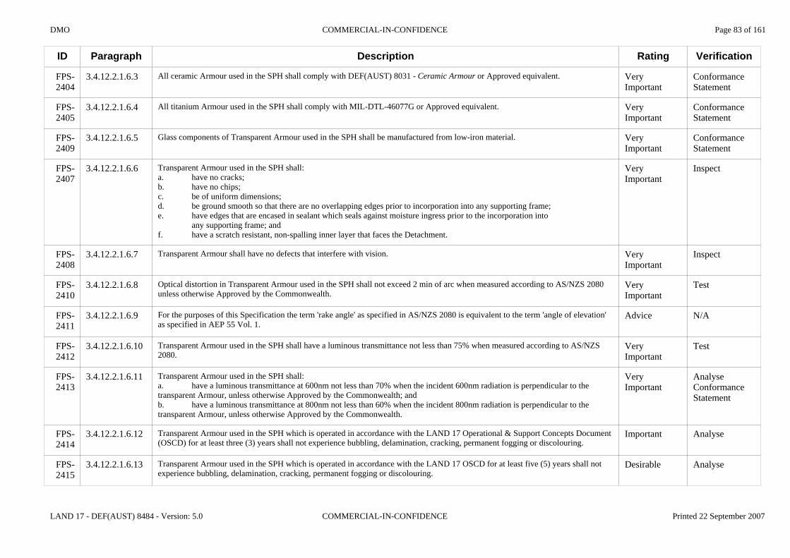
DMO COMMERCIAL-IN-CONFIDENCE Page 83 of 161
LAND 17 - DEF(AUST) 8484 - Version: 5.0 COMMERCIAL-IN-CONFIDENCE Printed 22 September 2007
ID
FPS-2404
FPS-2405
FPS-2409
FPS-2407
FPS-2408
FPS-2410
FPS-2411
FPS-2412
FPS-2413
FPS-2414
FPS-2415
Paragraph
3.4.12.2.1.6.3
3.4.12.2.1.6.4
3.4.12.2.1.6.5
3.4.12.2.1.6.6
3.4.12.2.1.6.7
3.4.12.2.1.6.8
3.4.12.2.1.6.9
3.4.12.2.1.6.10
3.4.12.2.1.6.11
3.4.12.2.1.6.12
3.4.12.2.1.6.13
Description
All ceramic Armour used in the SPH shall comply with DEF(AUST) 8031 - Ceramic Armour or Approved equivalent.
All titanium Armour used in the SPH shall comply with MIL-DTL-46077G or Approved equivalent.
Glass components of Transparent Armour used in the SPH shall be manufactured from low-iron material.
Transparent Armour used in the SPH shall:a. have no cracks;b. have no chips;c. be of uniform dimensions;d. be ground smooth so that there are no overlapping edges prior to incorporation into any supporting frame;e. have edges that are encased in sealant which seals against moisture ingress prior to the incorporation into
any supporting frame; andf. have a scratch resistant, non-spalling inner layer that faces the Detachment.
Transparent Armour shall have no defects that interfere with vision.
Optical distortion in Transparent Armour used in the SPH shall not exceed 2 min of arc when measured according to AS/NZS 2080 unless otherwise Approved by the Commonwealth.
For the purposes of this Specification the term 'rake angle' as specified in AS/NZS 2080 is equivalent to the term 'angle of elevation' as specified in AEP 55 Vol. 1.
Transparent Armour used in the SPH shall have a luminous transmittance not less than 75% when measured according to AS/NZS 2080.
Transparent Armour used in the SPH shall:a. have a luminous transmittance at 600nm not less than 70% when the incident 600nm radiation is perpendicular to the transparent Armour, unless otherwise Approved by the Commonwealth; andb. have a luminous transmittance at 800nm not less than 60% when the incident 800nm radiation is perpendicular to the transparent Armour, unless otherwise Approved by the Commonwealth.
Transparent Armour used in the SPH which is operated in accordance with the LAND 17 Operational & Support Concepts Document (OSCD) for at least three (3) years shall not experience bubbling, delamination, cracking, permanent fogging or discolouring.
Transparent Armour used in the SPH which is operated in accordance with the LAND 17 OSCD for at least five (5) years shall not experience bubbling, delamination, cracking, permanent fogging or discolouring.
Rating
Very Important
Very Important
Very Important
Very Important
Very Important
Very Important
Advice
Very Important
Very Important
Important
Desirable
Verification
Conformance Statement
Conformance Statement
Conformance Statement
Inspect
Inspect
Test
N/A
Test
AnalyseConformance Statement
Analyse
Analyse

DMO COMMERCIAL-IN-CONFIDENCE Page 84 of 161
LAND 17 - DEF(AUST) 8484 - Version: 5.0 COMMERCIAL-IN-CONFIDENCE Printed 22 September 2007
ID
FPS-2416
FPS-2417
FPS-2418
FPS-2606
FPS-2607
FPS-2608
FPS-2610
FPS-2611
FPS-2614
FPS-2615
FPS-2616
FPS-2617
FPS-2618
Paragraph
3.4.12.2.1.6.14
3.4.12.2.1.6.15
3.4.12.2.1.6.16
3.4.12.2.1.6.17
3.4.12.2.1.7
3.4.12.2.1.7.1
3.4.12.2.1.7.2
3.4.12.2.1.7.3
3.4.12.2.1.7.4
3.4.12.2.1.7.5
3.4.12.2.1.7.6
3.4.12.2.1.7.7
3.4.12.2.1.7.8
Description
When stored in accordance with manufacturer's instructions for at least 15 years Transparent Armour used in the SPH shall not experience bubbling, delamination, cracking, permanent fogging or discolouring.
Transparent Armour used in the SPH shall:a. be supplied with cleaning instructions detailing the cleaning method for the non-spalling layer; andb. not require proprietary cleaning methods or solvents.
Scratching of the non-spalling inner layer by cleaning will be considered as a Failure of the non-spalling inner layer.
The Tenderer will supply information in the Tender Response (TDR F-8) regarding the total thickness, areal density (kg/m2), allowable tolerances, individual ply thickness, ply composition and interply adhesive between each ply of the Transparent Armour used in the SPH.
3.4.12.2.1.7 Environmental Conditions and Decontamination
Protected Crew Compartment(s) shall comply with the durability requirements as specified in section 3.2.1 of DEF(AUST) 8032.
Protected Crew Compartment(s) shall comply with the transient drop requirements as specified in section 3.2.2 of DEF(AUST) 8032.
Protected Crew Compartment(s) shall comply with the water immersion requirements as specified in section 3.2.4 of DEF(AUST) 8032.
Protected Crew Compartment(s) shall comply with the temperature extreme requirements as specified in section 3.2.12 of DEF(AUST) 8032, except that -19°C will be used instead of -40°C.
The temperature extremes as specified in section 3.2.12 in DEF(AUST) 8032 will be verified for the Protected Crew Compartment(s) during ballistic testing as specified in section 4.2 of DEF(AUST) 8032.
Protected Crew Compartment(s) when operated in temperatures ranging from less than -19°C to -40°C, shall not incur a Failure worse than a 'Reversible Type A Failure' as specified in 2.6.2.1 of DEF(AUST) 5168.
Protected Crew Compartment(s) shall comply with the flammability requirements as specified in section 3.2.13 of DEF(AUST) 8032.
Protected Crew Compartment(s) shall comply with the fungal growth requirements as specified in section 3.2.14 of DEF(AUST) 8032.
Rating
Important
Very Important
Advice
Advice
N/A
Very Important
Very Important
Very Important
Very Important
Advice
Desirable
Very Important
Very Important
Verification
Analyse
DemonstrateInspect
N/A
N/A
N/A
Test
Test
Test
Test
N/A
Analyse
Test
Test
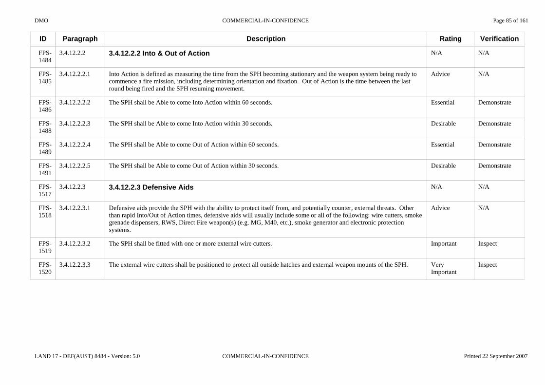
DMO COMMERCIAL-IN-CONFIDENCE Page 85 of 161
LAND 17 - DEF(AUST) 8484 - Version: 5.0 COMMERCIAL-IN-CONFIDENCE Printed 22 September 2007
ID
FPS-1484
FPS-1485
FPS-1486
FPS-1488
FPS-1489
FPS-1491
FPS-1517
FPS-1518
FPS-1519
FPS-1520
Paragraph
3.4.12.2.2
3.4.12.2.2.1
3.4.12.2.2.2
3.4.12.2.2.3
3.4.12.2.2.4
3.4.12.2.2.5
3.4.12.2.3
3.4.12.2.3.1
3.4.12.2.3.2
3.4.12.2.3.3
Description
3.4.12.2.2 Into & Out of Action
Into Action is defined as measuring the time from the SPH becoming stationary and the weapon system being ready to commence a fire mission, including determining orientation and fixation. Out of Action is the time between the last round being fired and the SPH resuming movement.
The SPH shall be Able to come Into Action within 60 seconds.
The SPH shall be Able to come Into Action within 30 seconds.
The SPH shall be Able to come Out of Action within 60 seconds.
The SPH shall be Able to come Out of Action within 30 seconds.
3.4.12.2.3 Defensive Aids
Defensive aids provide the SPH with the ability to protect itself from, and potentially counter, external threats. Other than rapid Into/Out of Action times, defensive aids will usually include some or all of the following: wire cutters, smoke grenade dispensers, RWS, Direct Fire weapon(s) (e.g. MG, M40, etc.), smoke generator and electronic protection systems.
The SPH shall be fitted with one or more external wire cutters.
The external wire cutters shall be positioned to protect all outside hatches and external weapon mounts of the SPH.
Rating
N/A
Advice
Essential
Desirable
Essential
Desirable
N/A
Advice
Important
Very Important
Verification
N/A
N/A
Demonstrate
Demonstrate
Demonstrate
Demonstrate
N/A
N/A
Inspect
Inspect

DMO COMMERCIAL-IN-CONFIDENCE Page 86 of 161
LAND 17 - DEF(AUST) 8484 - Version: 5.0 COMMERCIAL-IN-CONFIDENCE Printed 22 September 2007
ID
FPS-1859
FPS-1521
FPS-1522
FPS-4052
FPS-1864
FPS-2623
FPS-1789
FPS-2624
FPS-1523
FPS-4453
Paragraph
3.4.12.2.3.4
3.4.12.2.3.5
3.4.12.2.3.6
3.4.12.2.3.7
3.4.12.2.3.8
3.4.12.2.3.9
3.4.12.2.3.10
3.4.12.2.3.11
3.4.12.2.3.12
3.4.12.2.3.13
Description
At each of the nominated impact speeds (5 km/h and 60 km/h), the external wire cutters shall, without Damage to the wire cutters, be Able to cut a wire with the following characteristics:a. diameter ≤ 2.8 mm;b. nominal breaking strength of no less than 8.0 kN and no more than 16.0 kN;c. angles of incidence of
i. 70o to platform longitudinal axis,ii. 90o to platform longitudinal axis,iii. 110o to platform longitudinal axis; and
d. height above ground sufficient to injure Personnel located at each of the SPH upper surface hatches.
The SPH shall be fitted with a multispectral smoke dispensing system Able to create a smoke screen of at least 60m width and at least 4m depth centred on the longitudinal axis of the SPH at a range of no less than 30m from the front of the SPH.
The smoke dispensing system fitted to the SPH shall be Able to use at least one type of planned or in-service ADF smoke grenades.
Planned and in-service ADF smoke grenades consist of:a. 66 mm, Grenade Visual & Infra Red L114A1, NSN 1330-12-355-9616; andb. 76 mm, MASKE ST, NSN1330-12-348-9798.
The multispectral smoke dispensing system fitted to the SPH shall be fitted with two or more independently fireable dispensers.
The smoke dispensing system fitted to the SPH shall be Capable of being consecutively fired two or more times from each dispenser.
The SPH shall have a commander's hatch that enables a 360 degree field of view.
The SPH shall have a commander's hatch that enables self defence using personal small arms without the need to dismount the commander's seat.
The SPH shall be fitted with a stabilised RWS that is Capable of being operated behind armour whilst the gun is in action and when conducting tactical movement.
The RWS fitted to the SPH shall be Capable of fitting and firing the following current (and planned) in-service weapons:a. MAG58;b. 40 mm AGL: andc. .50 CAL.
Rating
Very Important
Very Important
Very Important
Advice
Important
Desirable
Important
Important
Essential
Advice
Verification
Test
Demonstrate
Demonstrate
N/A
Demonstrate
Demonstrate
Inspect
Inspect
Test
Demonstrate
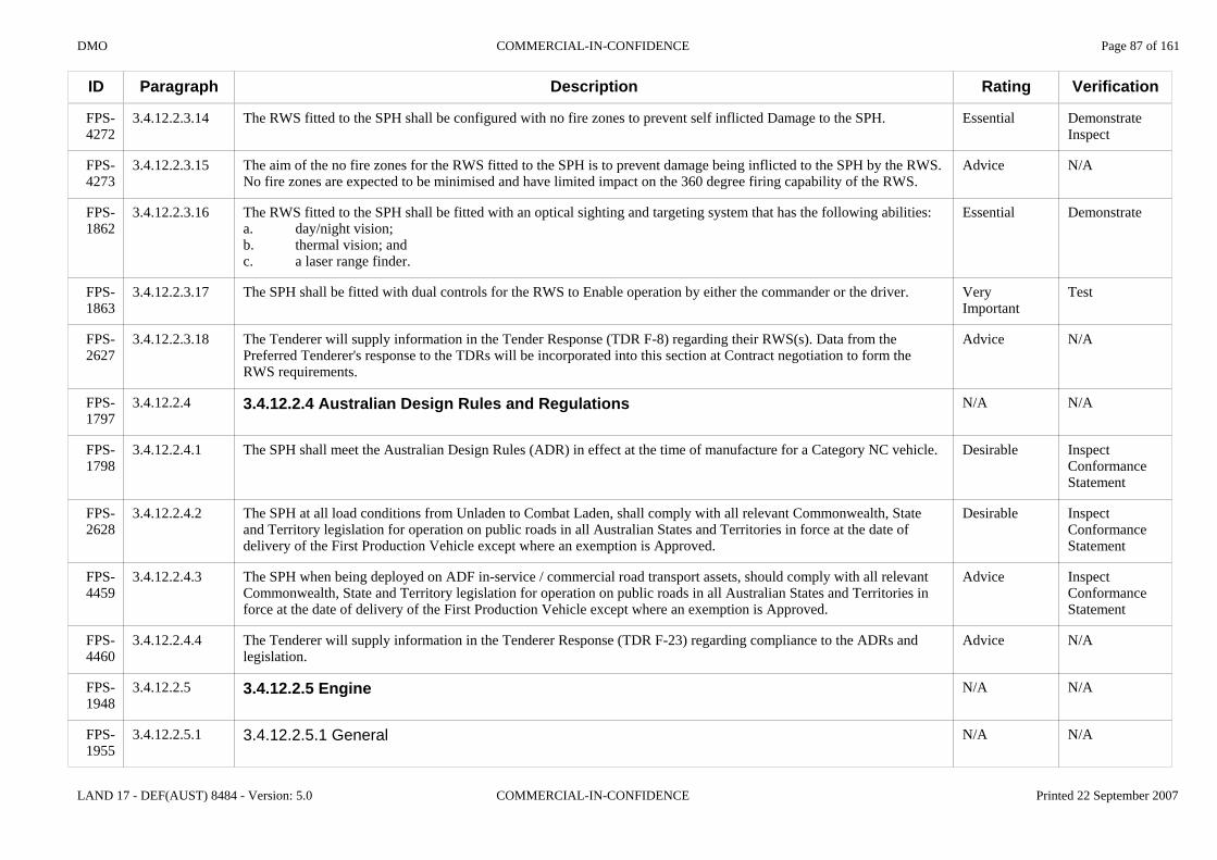
DMO COMMERCIAL-IN-CONFIDENCE Page 87 of 161
LAND 17 - DEF(AUST) 8484 - Version: 5.0 COMMERCIAL-IN-CONFIDENCE Printed 22 September 2007
ID
FPS-4272
FPS-4273
FPS-1862
FPS-1863
FPS-2627
FPS-1797
FPS-1798
FPS-2628
FPS-4459
FPS-4460
FPS-1948
FPS-1955
Paragraph
3.4.12.2.3.14
3.4.12.2.3.15
3.4.12.2.3.16
3.4.12.2.3.17
3.4.12.2.3.18
3.4.12.2.4
3.4.12.2.4.1
3.4.12.2.4.2
3.4.12.2.4.3
3.4.12.2.4.4
3.4.12.2.5
3.4.12.2.5.1
Description
The RWS fitted to the SPH shall be configured with no fire zones to prevent self inflicted Damage to the SPH.
The aim of the no fire zones for the RWS fitted to the SPH is to prevent damage being inflicted to the SPH by the RWS. No fire zones are expected to be minimised and have limited impact on the 360 degree firing capability of the RWS.
The RWS fitted to the SPH shall be fitted with an optical sighting and targeting system that has the following abilities:a. day/night vision;b. thermal vision; andc. a laser range finder.
The SPH shall be fitted with dual controls for the RWS to Enable operation by either the commander or the driver.
The Tenderer will supply information in the Tender Response (TDR F-8) regarding their RWS(s). Data from the Preferred Tenderer's response to the TDRs will be incorporated into this section at Contract negotiation to form the RWS requirements.
3.4.12.2.4 Australian Design Rules and Regulations
The SPH shall meet the Australian Design Rules (ADR) in effect at the time of manufacture for a Category NC vehicle.
The SPH at all load conditions from Unladen to Combat Laden, shall comply with all relevant Commonwealth, State and Territory legislation for operation on public roads in all Australian States and Territories in force at the date of delivery of the First Production Vehicle except where an exemption is Approved.
The SPH when being deployed on ADF in-service / commercial road transport assets, should comply with all relevant Commonwealth, State and Territory legislation for operation on public roads in all Australian States and Territories in force at the date of delivery of the First Production Vehicle except where an exemption is Approved.
The Tenderer will supply information in the Tenderer Response (TDR F-23) regarding compliance to the ADRs and legislation.
3.4.12.2.5 Engine
3.4.12.2.5.1 General
Rating
Essential
Advice
Essential
Very Important
Advice
N/A
Desirable
Desirable
Advice
Advice
N/A
N/A
Verification
DemonstrateInspect
N/A
Demonstrate
Test
N/A
N/A
InspectConformance Statement
InspectConformance Statement
InspectConformance Statement
N/A
N/A
N/A

DMO COMMERCIAL-IN-CONFIDENCE Page 88 of 161
LAND 17 - DEF(AUST) 8484 - Version: 5.0 COMMERCIAL-IN-CONFIDENCE Printed 22 September 2007
ID
FPS-2699
FPS-1957
FPS-1958
FPS-2367
FPS-2366
FPS-2368
FPS-2369
FPS-1953
FPS-1959
FPS-1961
FPS-1962
FPS-1963
FPS-1964
Paragraph
3.4.12.2.5.1.1
3.4.12.2.5.1.2
3.4.12.2.5.1.3
3.4.12.2.5.2
3.4.12.2.5.2.1
3.4.12.2.5.2.2
3.4.12.2.5.2.3
3.4.12.2.5.3
3.4.12.2.5.3.1
3.4.12.2.5.4
3.4.12.2.5.4.1
3.4.12.2.5.4.2
3.4.12.2.5.5
Description
The SPH main engine shall be Able to be started and shut down by the seated, restrained driver without the use of a key.
If the engine of the SPH is fitted with an automatic safety system for reducing the power of the engine or shutting the engine down,then there shall be a means by which the seated restrained driver can override this safety feature.
If the SPH is required to idle to cool engine components or sub-systems after operation then it shall be fitted with an automatic timing device that idles and then shuts down the engine after the required time with no driver intervention other than to activate the timing device.
3.4.12.2.5.2 Hot and Cold Starting
The engine of the SPH shall be Able to be started at ambient air temperatures up to 44 oC.
The engine of the SPH shall be Able to be started at ambient air temperatures down to -20 oC without pre-heating of the engine coolant and lubricants.
The engine of the SPH shall be Able to be started at ambient air temperatures down to -30 oC with pre-heating of the engine coolant and lubricants to -20 oC.
3.4.12.2.5.3 Air Intake
The SPH shall be fitted with:a. an engine air filter that complies with sections 3.2 to 3.6 inclusive of MIL-PRF-62048C or Approved equivalent; and / orb. an engine air induction system with a particulate pre-cleaner or particulate separator.
3.4.12.2.5.4 Cooling System
When the SPH is stationary, the engine coolant level shall be visible to the Detachment without the need to release cooling system pressure, or to remove any component from the SPH.
The cooling system heat exchanger on the SPH shall be fitted with an in-field removable protection device that prevents foreign matter larger than 3 mm in diameter passing through and reaching the heat exchanger.
3.4.12.2.5.5 Oil Sample Points
Rating
Very Important
Important
Important
N/A
Very Important
Very Important
Very Important
N/A
Important
N/A
Important
Important
N/A
Verification
Demonstrate
Demonstrate
Demonstrate
N/A
Demonstrate
Demonstrate
Demonstrate
N/A
TestInspect
N/A
Demonstrate
Demonstrate
N/A
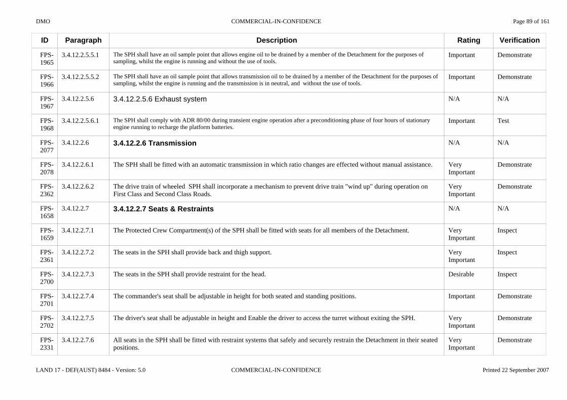
DMO COMMERCIAL-IN-CONFIDENCE Page 89 of 161
LAND 17 - DEF(AUST) 8484 - Version: 5.0 COMMERCIAL-IN-CONFIDENCE Printed 22 September 2007
ID
FPS-1965
FPS-1966
FPS-1967
FPS-1968
FPS-2077
FPS-2078
FPS-2362
FPS-1658
FPS-1659
FPS-2361
FPS-2700
FPS-2701
FPS-2702
FPS-2331
Paragraph
3.4.12.2.5.5.1
3.4.12.2.5.5.2
3.4.12.2.5.6
3.4.12.2.5.6.1
3.4.12.2.6
3.4.12.2.6.1
3.4.12.2.6.2
3.4.12.2.7
3.4.12.2.7.1
3.4.12.2.7.2
3.4.12.2.7.3
3.4.12.2.7.4
3.4.12.2.7.5
3.4.12.2.7.6
Description
The SPH shall have an oil sample point that allows engine oil to be drained by a member of the Detachment for the purposes of sampling, whilst the engine is running and without the use of tools.
The SPH shall have an oil sample point that allows transmission oil to be drained by a member of the Detachment for the purposes of sampling, whilst the engine is running and the transmission is in neutral, and without the use of tools.
3.4.12.2.5.6 Exhaust system
The SPH shall comply with ADR 80/00 during transient engine operation after a preconditioning phase of four hours of stationary engine running to recharge the platform batteries.
3.4.12.2.6 Transmission
The SPH shall be fitted with an automatic transmission in which ratio changes are effected without manual assistance.
The drive train of wheeled SPH shall incorporate a mechanism to prevent drive train "wind up" during operation on First Class and Second Class Roads.
3.4.12.2.7 Seats & Restraints
The Protected Crew Compartment(s) of the SPH shall be fitted with seats for all members of the Detachment.
The seats in the SPH shall provide back and thigh support.
The seats in the SPH shall provide restraint for the head.
The commander's seat shall be adjustable in height for both seated and standing positions.
The driver's seat shall be adjustable in height and Enable the driver to access the turret without exiting the SPH.
All seats in the SPH shall be fitted with restraint systems that safely and securely restrain the Detachment in their seated positions.
Rating
Important
Important
N/A
Important
N/A
Very Important
Very Important
N/A
Very Important
Very Important
Desirable
Important
Very Important
Very Important
Verification
Demonstrate
Demonstrate
N/A
Test
N/A
Demonstrate
Demonstrate
N/A
Inspect
Inspect
Inspect
Demonstrate
Demonstrate
Demonstrate

DMO COMMERCIAL-IN-CONFIDENCE Page 90 of 161
LAND 17 - DEF(AUST) 8484 - Version: 5.0 COMMERCIAL-IN-CONFIDENCE Printed 22 September 2007
ID
FPS-4312
FPS-1696
FPS-1660
FPS-1661
FPS-1662
FPS-1663
FPS-1147
FPS-1148
FPS-4290
Paragraph
3.4.12.2.7.7
3.4.12.2.7.8
3.4.12.2.7.9
3.4.12.2.7.10
3.4.12.2.7.11
3.4.12.2.7.12
3.4.12.2.8
3.4.12.2.8.1
3.4.12.2.8.2
Description
The SPH shall be fitted with seats, seat anchorages, seatbelt and seatbelt anchorages that comply with ADRs for a Category NC vehicle.
All seats in the SPH shall protect the Detachment in their normal travelling positions in the event of a lateral roll-over of the platform.
All seats and seat restraint systems in the SPH shall accommodate Personnel wearing a Combat Vehicle Communication Headset (CVCH) or Kevlar Combat Helmet (KCH).
All seats and seat restraint systems in the SPH shall accommodate Personnel wearing each of the following:a. Combat Body Armour;b. Individual Protection Equipment; andc. Combat Body Armour and Individual Protection Equipment.
Seat restraints shall be Able to be removed by the Person sitting in the seat in an elapsed time of no more than five seconds.
When a 95th Percentile Male soldier is seated and restrained in the SPH, there shall be no less than 50 mm clear space above the soldier whilst wearing each of:a. CVCH; andb. KCH.
3.4.12.2.8 Fuels & Lubricants
Whilst using "Diesel Fuel Auto" as specified in DEF(AUST) 206 (latest edition) and in a fully operational state, the SPH engine shall operate according to its specification.
The SPH will be required to run on Turbine, Fuel Aviation as an alternative to Diesel Fuel Auto. F-34 is the generic term for Turbine, Fuel Aviation and includes:a. Australian F-34 manufactured to DEF(AUST) 5240D;b. USA JP-8 manufactured to MIL-DTL-83133E; andc. British F-34 manufactured to DEFSTAN 91-87;d. F-34 fuels which are listed within and meet the requirements of NATO STANAG 3747 and/or ASIC 15/6.F-34 manufactured to these different standards are interchangeable but not identical.
Rating
Important
Very Important
Very Important
Very Important
Very Important
Important
N/A
Essential
Advice
Verification
AnalyseInspect
DemonstrateConformance Statement
Demonstrate
Demonstrate
Demonstrate
Inspect
N/A
TestConformance Statement
N/A
DMO COMMERCIAL-IN-CONFIDENCE Page 91 of 161
LAND 17 - DEF(AUST) 8484 - Version: 5.0 COMMERCIAL-IN-CONFIDENCE Printed 22 September 2007
ID
FPS-1149
FPS-4288
FPS-4289
FPS-4306
FPS-1167
FPS-4291
FPS-1974
FPS-1909
Paragraph
3.4.12.2.8.3
3.4.12.2.8.4
3.4.12.2.8.5
3.4.12.2.8.6
3.4.12.2.8.7
3.4.12.2.8.8
3.4.12.2.8.9
3.4.12.2.8.10
Description
Whilst using "F-34" fuel (Turbine Fuel, Aviation) as specified in DEF(AUST) 5240D and in a fully operational state, the SPH engine shall operate according to its specification without modification:a. with no more than 10% power loss;b. with no more than 10% torque loss; andc. without any adverse effect on reliability.
Whilst using "JP-8" fuel (Turbine Fuel, Aviation) as specified in MIL-DTL-83133E and in a fully operational state, the SPH engine shall operate according to its specification without modification:a. with no more than 10% power loss;b. with no more than 10% torque loss; andc. without any adverse effect on reliability.
Whilst using "F-34" fuel (Turbine Fuel, Aviation) as specified in DEFSTAN 91-87 and in a fully operational state, the SPH engine shall operate according to its specification without modification:a. with no more than 10% power loss;b. with no more than 10% torque loss; andc. without any adverse effect on reliability.
Whilst using an "F-34" fuel (Turbine Fuel, Aviation) which is listed within and meets the requirements of STANAG 3747 and/or ASIC 15/6 and in a fully operational state, the SPH engine shall operate according to its specification without modification:a. with no more than 10% power loss;b. with no more than 10% torque loss; andc. without any adverse effect on reliability.
Generators and Auxiliary Power Units (APU) fitted to the SPH shall operate according to their design specifications with "Diesel Fuel Auto" as specified in DEF(AUST) 206 (latest edition).
Generators and APUs fitted to the SPH shall operate according to their design specifications with "F-34" fuels as specified in DEF(AUST) 5240D, MIL-DTL-83133E, DEFSTAN 91-87, STANAG 3747 or ASIC 15/6.
The fuel storage system on the SPH shall be completely filled from a single filling point.
When the SPH is standing on level ground, its fuel storage system shall be filled without spillage from:a. a fuel nozzle with an outside diameter of no more than 50mm; andc. at a rate greater than 66 l/min.
Rating
Very Important
Very Important
Very Important
Very Important
Very Important
Very Important
Important
Very Important
Verification
TestConformance Statement
TestConformance Statement
TestConformance Statement
TestConformance Statement
DemonstrateConformance Statement
DemonstrateConformance Statement
Demonstrate
DemonstrateInspect

DMO COMMERCIAL-IN-CONFIDENCE Page 92 of 161
LAND 17 - DEF(AUST) 8484 - Version: 5.0 COMMERCIAL-IN-CONFIDENCE Printed 22 September 2007
ID
FPS-1910
FPS-1975
FPS-1969
FPS-1970
FPS-1976
FPS-1977
FPS-1971
FPS-1161
FPS-1994
FPS-2008
FPS-2012
FPS-1995
FPS-2000
Paragraph
3.4.12.2.8.11
3.4.12.2.8.12
3.4.12.2.8.13
3.4.12.2.8.14
3.4.12.2.8.15
3.4.12.2.8.16
3.4.12.2.8.17
3.4.12.2.9
3.4.12.2.9.1
3.4.12.2.9.1.1
3.4.12.2.9.1.2
3.4.12.2.9.2
3.4.12.2.9.2.1
Description
When the SPH is standing on level ground, its fuel storage system shall be filled without spillage using:a. a 20 litre jerry can (NSN-7240-99-802-2405) included as part of the platform CES;b. without the need to remove components from the SPH other than the fuel storage system filler cap; andc. without the need for a funnel.
The fuel storage system safety vent on the SPH shall not be combined with or connected to any other vent system.
If the fuel storage system on the SPH incorporates multiple tanks then each tank shall be Able to be isolated from the other tank(s) such that the SPH remains operational.
The fuel storage system on the SPH shall be fitted with a removable strainer, at the filling point to prevent the ingress of any object larger than 1 mm in diameter during refuelling.
The SPH fuel system shall supply fuel to the engine and APU(s) on all Gradients and sideslopes between level ground and those stated in the SP Mobility section [FPS-1911] in this Specification, at a fuel load of less than 10% of the maximum useable fuel load of the internal fuel storage system.
The fuel storage system on the SPH shall have a means of draining the complete fuel load of the internal fuel storage system when on level ground, using only items in Annex A of this Specification and without the removal of any other component from the SPH.
The fuel storage system filler cap on the SPH shall be captive.
3.4.12.2.9 Electrical
3.4.12.2.9.1 General
The 24VDC negative earth system on the SPH shall comply with Army(AUST) 6869.
The 24VDC negative earth electrical system on the SPH shall use only circuit breakers for overcurrent protection.
3.4.12.2.9.2 Alternator
The alternator of the SPH, with the main engine at Fast Idle, shall be Able to charge the platform batteries whilst operating undermaximum electrical operating load.
Rating
Very Important
Very Important
Important
Important
Desirable
Desirable
Desirable
N/A
N/A
Important
Important
N/A
Important
Verification
DemonstrateInspect
Demonstrate
Demonstrate
Demonstrate
Demonstrate
DemonstrateInspect
Inspect
N/A
N/A
Test
Inspect
N/A
Analyse

DMO COMMERCIAL-IN-CONFIDENCE Page 93 of 161
LAND 17 - DEF(AUST) 8484 - Version: 5.0 COMMERCIAL-IN-CONFIDENCE Printed 22 September 2007
ID
FPS-2001
FPS-2002
FPS-1996
FPS-1999
FPS-2014
FPS-2015
FPS-2016
FPS-2003
FPS-2004
FPS-2005
FPS-2006
FPS-2007
FPS-1997
FPS-2027
Paragraph
3.4.12.2.9.2.2
3.4.12.2.9.2.3
3.4.12.2.9.3
3.4.12.2.9.3.1
3.4.12.2.9.3.2
3.4.12.2.9.3.3
3.4.12.2.9.3.4
3.4.12.2.9.3.5
3.4.12.2.9.3.6
3.4.12.2.9.3.7
3.4.12.2.9.3.8
3.4.12.2.9.3.9
3.4.12.2.10
3.4.12.2.10.1
Description
The alternator of the SPH, with the main engine at Fast Idle, shall be Able to charge the SPH automotive batteries to 90% of their fully charged state (as defined in EMEI Electrical M 029) from a discharged state (as defined in EMEI Electrical M 029) within 2 hours whilst operating under maximum electrical operating load.
The alternator of the SPH, with the main engine at Fast Idle and with the SPH operating under maximum electrical operating load, shall be Able to supply electrical power with no less than 25% reserve capacity.
3.4.12.2.9.3 Batteries
The SPH electrical system shall always maintain sufficient reserve capacity to start the main engine.
The battery cold cranking ability shall be greater than SPH cold cranking requirements, when the battery state of charge is 10% of the fully charged state as specified in EMEI Electrical M 029.
The SPH shall permit one member of the Detachment at a time to fit batteries using only items from Annex A of this Specification.
The SPH shall permit one member of the Detachment at a time to disconnect and remove batteries using only items from Annex A of this Specification.
The SPH shall be fitted with an external 24VDC battery charging receptacle.
The battery charging receptacle shall be accessible to Personnel standing on the ground adjacent to the SPH.
The battery charging receptacle and associated circuitry shall permit battery chargers specified in EMEI Electrical M 029 to charge the SPH automotive batteries.
The SPH shall be fitted with an external 24VDC inter-vehicle starting receptacle NSN 5935-01-497-2173 or an Approved equivalent.
The intervehicle starting receptacle shall be accessible to Personnel standing on the ground adjacent to the SPH.
3.4.12.2.10 Lighting
3.4.12.2.10.1 General
Rating
Important
Important
N/A
Very Important
Important
Important
Important
Important
Important
Important
Important
Important
N/A
N/A
Verification
Analyse
Analyse
N/A
AnalyseInspect
Demonstrate
Demonstrate
Demonstrate
AnalyseInspect
Inspect
Demonstrate
Inspect
Inspect
N/A
N/A
DMO COMMERCIAL-IN-CONFIDENCE Page 94 of 161
LAND 17 - DEF(AUST) 8484 - Version: 5.0 COMMERCIAL-IN-CONFIDENCE Printed 22 September 2007
ID
FPS-3520
FPS-2028
FPS-2919
FPS-2080
FPS-2650
FPS-2322
FPS-2655
FPS-2329
FPS-2452
FPS-2470
FPS-2050
FPS-2666
FPS-4309
Paragraph
3.4.12.2.10.1.1
3.4.12.2.10.1.2
3.4.12.2.10.1.3
3.4.12.2.10.1.4
3.4.12.2.10.2
3.4.12.2.10.2.1
3.4.12.2.10.2.2
3.4.12.2.10.2.3
3.4.12.2.10.2.4
3.4.12.2.10.2.5
3.4.12.2.10.2.6
3.4.12.2.10.2.7
3.4.12.2.10.2.8
Description
The SPH shall have internal and external lighting systems that are suitable for use in the full range of platform operating conditions and environments.
The lights on the SPH shall have an operating life of greater than 10 000 h except for the headlights.
If fitted, LED lights on the SPH shall comply with SAE J1889, regardless of SPH width.
The lighting system of the SPH shall provide illumination that is compatible with NVG in all lighting modes other than the Interior Normal Lighting mode.
3.4.12.2.10.2 Interior
The SPH shall have the following interior lighting modes:a. Interior Normal Lighting;b. Interior Reduced Lighting; andc. No Lighting.
The SPH shall have a lighting circuit master switch.
The SPH lighting circuit master switch shall:a. be Able to switch between the interior lighting modes;b. be Able to be operated by the seated commander; andc. be Able to be operated by all members of the Detachment other than the driver within the Protected Crew Compartment.
The interior lighting of the SPH shall enable the driver to read and operate the drivers' console.
The interior lighting of the SPH shall enable the reading of coloured maps by the Detachment in all lighting modes other than the NoLighting.
When the SPH is operating in the Interior Normal Lighting mode the lighting system shall be Able to be set to automatically switch from Interior Normal Lighting to Reduced Lighting when any or all of the hatches and doors on the SPH are opened.
The SPH electrical system shall have a means to prevent inadvertent switching from the Interior Reduced Lighting mode to the Interior Normal Lighting mode.
The SPH internal failure warning lights shall activate in all interior and exterior lighting modes.
Rating
Very Important
Desirable
Important
Very Important
N/A
Very Important
Very Important
Very Important
Very Important
Important
Very Important
Important
Important
Verification
N/A
Conformance Statement
AnalyseInspect
Demonstrate
N/A
Demonstrate
Inspect
Demonstrate
Demonstrate
Demonstrate
Demonstrate
Demonstrate
Demonstrate

DMO COMMERCIAL-IN-CONFIDENCE Page 95 of 161
LAND 17 - DEF(AUST) 8484 - Version: 5.0 COMMERCIAL-IN-CONFIDENCE Printed 22 September 2007
ID
FPS-2651
FPS-2654
FPS-2657
FPS-2031
FPS-2454
FPS-2658
FPS-4401
FPS-4402
FPS-2674
FPS-4403
FPS-4404
FPS-2659
FPS-2672
Paragraph
3.4.12.2.10.3
3.4.12.2.10.3.1
3.4.12.2.10.3.2
3.4.12.2.10.3.3
3.4.12.2.10.3.4
3.4.12.2.10.3.5
3.4.12.2.10.3.5.1
3.4.12.2.10.3.5.2
3.4.12.2.10.3.6
3.4.12.2.10.3.6.1
3.4.12.2.10.3.6.2
3.4.12.2.10.3.7
3.4.12.2.10.3.8
Description
3.4.12.2.10.3 Exterior
The SPH shall have the following exterior lighting modes:a. Exterior Normal Lighting;b. Blackout Lighting;c. Exterior Reduced Lighting; andd. No Lighting.
The exterior lighting modes shall be Able to be operated by the seated, restrained driver.
All lights that are permanently externally located on the SPH shall have a means of protection against crash damage that does not affect the lights function.
The front and rear exterior lighting of the SPH shall comply with ADRs for a Category NC vehicle.
The SPH shall be fitted with the following blackout lighting system elements for the front of the SPH:
a. blackout driving and blackout front marker lamps; and
b. a single driving convoy lamp.
The SPH shall be fitted with the following blackout lighting system elements for the rear of the SPH:
a. blackout tail and stop and blackout rear marker lamps; and
b. a single convoy lamp.
The lamps prescribed in FPS-2658 and FPS-2674 shall comply with STANAG 4381 ed. 1.
The lamps prescribed in FPS-2658 and FPS-2674 shall be utilised in the Blackout Lighting mode.
Rating
N/A
Very Important
Very Important
Important
Important
Very Important
Very Important
Important
Very Important
Very Important
Very Important
Very Important
Very Important
Verification
N/A
Demonstrate
Demonstrate
Inspect
Conformance Statement
Inspect
Inspect
Inspect
Inspect
Inspect
Inspect
DemonstrateConformance Statement
Demonstrate

DMO COMMERCIAL-IN-CONFIDENCE Page 96 of 161
LAND 17 - DEF(AUST) 8484 - Version: 5.0 COMMERCIAL-IN-CONFIDENCE Printed 22 September 2007
ID
FPS-1716
FPS-2524
FPS-1717
FPS-1744
FPS-1747
FPS-1746
FPS-2364
FPS-1749
FPS-2363
FPS-2319
FPS-2351
FPS-2365
Paragraph
3.4.12.2.11
3.4.12.2.11.1
3.4.12.2.11.2
3.4.12.2.11.3
3.4.12.2.11.4
3.4.12.2.11.5
3.4.12.2.11.6
3.4.12.2.11.7
3.4.12.2.11.8
3.4.12.2.11.9
3.4.12.2.11.10
3.4.12.2.11.11
Description
3.4.12.2.11 Climate Control
All requirements in this section are to be met under all environmental conditions specified in the Environmental Conditions section [FPS-31] of this Specification.
The Protected Crew Compartment(s) of the SPH shall be fitted with a user adjustable climate control system that meets the requirements of MIL-STD-1472F, section 5.8.1 Heating, Ventilating and Air Conditioning.
The climate control system of the SPH shall provide a means for temperature and humidity adjustment for the Protected Crew Compartment(s).
The operating controls for the climate control system of the SPH shall be accessible by the Detachment in each occupied Protected Crew Compartment(s).
The climate control system of the SPH shall be Able to provide external fresh air to the Protected Crew Compartment(s).
The climate control system of the SPH shall filter dust and particles from external air drawn into the Protected Crew Compartment(s).
The climate control system of the SPH shall be Able to prevent external air entering the Protected Crew Compartment(s).
The climate control system of the SPH shall be Able to recirculate internal air through the Protected Crew Compartment(s).
The climate control system of the SPH shall be Able to maintain the temperature of the Protected Crew Compartment(s) at an Operator selected setting in the range 15-30 oC in all of the environmental conditions specified in the Environmental Conditions section [FPS-31] of this Specification.
The climate control system of the SPH shall be Able to reduce the internal temperature of the Protected Crew Compartment(s) to no more than 29 oC within 30 minutes after:a. the SPH has been soaked for at least 2 hours at an ambient air temperature of 44 oC;b. with a direct solar radiation of 1120 W/m2 applied to the SPH;c. the engine having been shut down during the soaking period;d. the climate control system having been shut down during the soaking period; ande. the initial Protected Crew Compartment(s) internal temperature of no less than 29 oC.
The climate control system of the SPH shall be Able to maintain the internal temperature of the charge Magazine(s) at 21 oC.
Rating
N/A
Advice
Very Important
Very Important
Very Important
Very Important
Very Important
Very Important
Very Important
Very Important
Desirable
Important
Verification
N/A
N/A
Inspect
Demonstrate
Inspect
Demonstrate
Demonstrate
Demonstrate
Demonstrate
Demonstrate
Test
Test

DMO COMMERCIAL-IN-CONFIDENCE Page 97 of 161
LAND 17 - DEF(AUST) 8484 - Version: 5.0 COMMERCIAL-IN-CONFIDENCE Printed 22 September 2007
ID
FPS-2352
FPS-1745
FPS-3549
FPS-1718
FPS-1719
FPS-1783
FPS-2310
FPS-2311
FPS-2312
FPS-2525
FPS-2526
Paragraph
3.4.12.2.11.12
3.4.12.2.11.13
3.4.12.2.11.14
3.4.12.2.12
3.4.12.2.12.1
3.4.12.2.12.2
3.4.12.2.12.3
3.4.12.2.12.4
3.4.12.2.12.5
3.4.12.2.12.6
3.4.12.2.12.7
Description
The climate control system of the SPH shall provide a means for temperature and humidity adjustment in the charge Magazine(s).
It is envisaged that the SPH will have the capability to control the climate inside the Protected Crew Compartment(s) when in CBNR threat environments. The Climate Control section [FPS-1716] of this Specification should be read in conjunction with the CBNRD Protection section [FPS-587] of this Specification.
The SPH shall meet the requirements of the Climate Control section [FPS-1716] of this Specification whilst meeting the requirements in the CBNRD Protection section of this Specification [FPS-587].
3.4.12.2.12 Central Tyre Inflation System
This section only applies to wheeled SPH.
Wheeled versions of the SPH shall be fitted with a Central Tyre Inflation System (CTIS) that is user adjustable by the driver whilst protected under armour.
The wheeled SPH CTIS shall enable the seated, restrained driver to simultaneously adjust the inflation pressure for all wheel and tyre assemblies fitted to the SPH whilst the SPH is in motion.
The wheeled SPH CTIS shall have preset pressure settings that enable the Combat Laden wheeled version of the SPH to travel at the maximum speed possible without damage to the wheels, tyres and SPH over the following terrain:a. First Class and Second Class Roads at speeds up to and including the top speed of the SPH;b. Cross Country at speeds up to and including the safe maximum speed for Cross Country traversal; andc. mud and sand at speeds up to and including the safe maximum speed for mud and sand traversal.
The wheeled SPH CTIS shall visually and audibly warn the seated, restrained driver if the CTIS recommended speed is exceeded for a given preset pressure.
The wheeled SPH CTIS shall simultaneously inflate all wheel and tyre assemblies from the OEM's recommended inflation pressure for operation in sand at a speed of 15 km/h to the OEM's recommended inflation pressure for operation on First Class Roads at the maximum road speed in less than 10 min, with all pneumatic reservoirs fully charged prior to starting the inflation.
The wheeled SPH CTIS shall simultaneously deflate all wheel and tyre assemblies from the OEM's recommended inflation pressure for operation on First Class Roads at the maximum road speed to the OEM's recommended inflation pressure for operation in sand at a speed of 15 km/h in less than 10 min.
Rating
Desirable
Advice
Important
N/A
Advice
Very Important
Very Important
Important
Important
Important
Important
Verification
Demonstrate
N/A
Demonstrate
N/A
N/A
Demonstrate
Demonstrate
DemonstrateInspect
DemonstrateInspect
Demonstrate
Demonstrate

DMO COMMERCIAL-IN-CONFIDENCE Page 98 of 161
LAND 17 - DEF(AUST) 8484 - Version: 5.0 COMMERCIAL-IN-CONFIDENCE Printed 22 September 2007
ID
FPS-2059
FPS-2060
FPS-2061
FPS-2662
FPS-2062
FPS-2063
FPS-2663
…
Paragraph
3.4.12.2.13
3.4.12.2.13.1
3.4.12.2.13.2
3.4.12.2.13.3
3.4.12.2.13.4
3.4.12.2.13.5
3.4.12.2.13.6
Description
3.4.12.2.13 Axles/Suspension
This section only applies to wheeled SPH.
Axles fitted to the wheeled SPH shall have a means of preventing the loss of torque from any driven wheel when another driven wheel(s) has lost traction.
The Combat Laden wheeled SPH shall allow the steering mechanism to be turned from the extreme left position to the extreme right position of possible movement without Damage.
The Combat Laden wheeled SPH shall meet the requirements of clause FPS-2662 with all of the steerable wheels on the left hand side located at a vertical obstacle height of 500 mm and all of the wheels on the right hand side at ground level as illustrated in the Position A of Figure 3.4.12.2.13-1.
The Combat Laden wheeled SPH shall meet the requirements of clause FPS-2662 with all of the steerable wheels on the right hand side located at a vertical obstacle height of 500 mm and all of the wheels on the left hand side at ground level as illustrated in the position B of Figure 3.4.12.2.13-1.
Rating
N/A
Advice
Very Important
Very Important
Important
Important
Advice
Verification
N/A
N/A
Demonstrate
Demonstrate
DemonstrateConformance Statement
DemonstrateConformance Statement
N/A

DMO COMMERCIAL-IN-CONFIDENCE Page 99 of 161
LAND 17 - DEF(AUST) 8484 - Version: 5.0 COMMERCIAL-IN-CONFIDENCE Printed 22 September 2007
ID
FPS-2663
FPS-3451
FPS-2064
FPS-2665
…
Paragraph
3.4.12.2.13.6.1
3.4.12.2.13.7
3.4.12.2.13.8
Description
Figure 3.4.12.2.13-1: Vertical Obstacle
The Combat Laden wheeled SPH shall negotiate the simple articulation gauge detailed in Figure 3.4.12.2.13-2 without Damage.
Rating
Advice
Important
Advice
Verification
N/A
Demonstrate
N/A

DMO COMMERCIAL-IN-CONFIDENCE Page 100 of 161
LAND 17 - DEF(AUST) 8484 - Version: 5.0 COMMERCIAL-IN-CONFIDENCE Printed 22 September 2007
ID
FPS-2665
FPS-3452
FPS-2065
Paragraph
3.4.12.2.13.8.1
3.4.12.2.13.9
Description
1135 1135
GROUND
Section A-A
A
A
3040
840 1430 840
150
150
Direction of Travel
810
Figure 3.4.12.2.13-2: Simple Articulation Gauge. (Dimensions in mm). Width > width of SPH.
The Combat Laden wheeled SPH shall negotiate the compound articulation gauge detailed in Figure 3.4.12.2.13-3 without Damage.
Rating
Advice
Important
Verification
N/A
Demonstrate
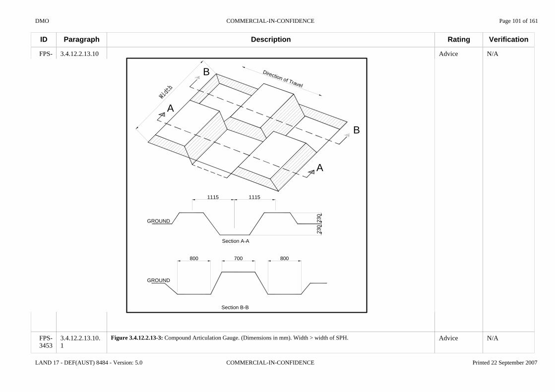
DMO COMMERCIAL-IN-CONFIDENCE Page 101 of 161
LAND 17 - DEF(AUST) 8484 - Version: 5.0 COMMERCIAL-IN-CONFIDENCE Printed 22 September 2007
ID
FPS-2660
FPS-3453
Paragraph
3.4.12.2.13.10
3.4.12.2.13.10.1
Description
1115 1115
GROUND
Section A-A
A
A
B
B
3040
800 700 800
Section B-B
GROUND
230
230
Direction of Travel
Figure 3.4.12.2.13-3: Compound Articulation Gauge. (Dimensions in mm). Width > width of SPH.
Rating
Advice
Advice
Verification
N/A
N/A

DMO COMMERCIAL-IN-CONFIDENCE Page 102 of 161
LAND 17 - DEF(AUST) 8484 - Version: 5.0 COMMERCIAL-IN-CONFIDENCE Printed 22 September 2007
ID
FPS-2066
FPS-2067
FPS-2069
FPS-2068
FPS-2070
FPS-2071
FPS-2072
FPS-2073
FPS-2643
FPS-2074
FPS-2075
FPS-2076
FPS-2644
FPS-2641
Paragraph
3.4.12.2.14
3.4.12.2.14.1
3.4.12.2.14.1.1
3.4.12.2.14.1.2
3.4.12.2.14.2
3.4.12.2.14.2.1
3.4.12.2.14.2.2
3.4.12.2.14.2.3
3.4.12.2.14.2.4
3.4.12.2.14.3
3.4.12.2.14.3.1
3.4.12.2.14.3.2
3.4.12.2.14.3.3
3.4.12.2.14.4
Description
3.4.12.2.14 Wheels and Tyres
3.4.12.2.14.1 General
This section only applies to wheeled SPH.
All wheel and tyre assemblies fitted to the wheeled SPH shall be identical.
3.4.12.2.14.2 Wheels
Each wheel fitted to the wheeled SPH shall comply with the Tyre and Rim Association Standards Manual or Approved equivalent.
Each wheel fitted to the wheeled SPH shall comply with SAE J1992.
The Tenderer will supply information in the Tender Response (TDR F-22) regarding the wheel and tyre replacement procedure if split rims are used in the construction of the wheel and tyre assemblies for the wheeled version of the SPH. As a minimum paragraph 2.3 of TDR F-22 should be completed.
If split rims are used in the construction of the wheels fitted to the wheeled SPH then the wheel and tyre replacement procedure shall be such that the safety of all maintenance Personnel is ensured.
3.4.12.2.14.3 Tyres
Each tyre fitted to the wheeled SPH shall comply with the Tyre and Rim Association Standards Manual or an Approved equivalent.
Each tyre fitted to the wheeled SPH shall comply with SAE J2014.
Each tyre fitted to the wheeled SPH shall be of radial ply construction.
3.4.12.2.14.4 Run Flat Tyres
Rating
N/A
N/A
Advice
Very Important
N/A
Very Important
Desirable
Advice
Very Important
N/A
Very Important
Important
Important
N/A
Verification
N/A
N/A
N/A
Inspect
N/A
Analyse
Analyse
N/A
Conformance Statement
N/A
Analyse
Inspect
Conformance Statement
N/A

DMO COMMERCIAL-IN-CONFIDENCE Page 103 of 161
LAND 17 - DEF(AUST) 8484 - Version: 5.0 COMMERCIAL-IN-CONFIDENCE Printed 22 September 2007
ID
FPS-1796
FPS-1871
FPS-2315
FPS-1911
FPS-2528
FPS-1912
FPS-1913
FPS-1914
FPS-1915
FPS-2640
…
Paragraph
3.4.12.2.14.4.1
3.4.12.2.14.4.2
3.4.12.2.14.4.3
3.4.12.2.15
3.4.12.2.15.1
3.4.12.2.15.2
3.4.12.2.15.3
3.4.12.2.15.4
3.4.12.2.15.5
3.4.12.2.15.6
Description
Wheeled versions of the SPH shall be fitted with a "run flat" tyre system on all wheel and tyre assemblies.
Where a run flat system is fitted to the tyres, the platform wheels shall incorporate a means of identifying that the run flat system is fitted.
The "run flat" tyre system shall Enable the wheeled version of the SPH to be driven:a. with two flat, punctured tyres;b. without the tyres coming off the rims;c. without starting a self sustaining fire; andd. over a continuous profile of 10 km Cross Country at 20 km/hr and 20 km on Second Class Roads at 25 km/hr.
3.4.12.2.15 Mobility
The Tenderer's response (TDR F-4) will be used by the Commonwealth to assess mobility category of the proposed platform.
The SPH shall comply with the specification limits of mobility category MC3 as defined in DEF(AUST) 8033.
The SPH shall comply with the specification limits of mobility category MC2 -Low as defined in DEF(AUST) 8033.
The SPH shall comply with the specification limits of mobility category MC2-High as defined in DEF(AUST) 8033.
The SPH shall have an unprepared fording depth of no less than 750 mm when traversing the concrete water obstacle as shown in Figure 3.4.12.2.15-1.
Rating
Very Important
Important
Important
N/A
Advice
Essential
Very Important
Important
Essential
Advice
Verification
Demonstrate
Inspect
Demonstrate
N/A
N/A
Analyse
Analyse
Analyse
AnalyseConformance Statement
N/A

DMO COMMERCIAL-IN-CONFIDENCE Page 104 of 161
LAND 17 - DEF(AUST) 8484 - Version: 5.0 COMMERCIAL-IN-CONFIDENCE Printed 22 September 2007
ID
FPS-2640
FPS-3454
FPS-2316
FPS-1916
FPS-2645
FPS-4264
Paragraph
3.4.12.2.15.6.1
3.4.12.2.15.7
3.4.12.2.15.8
3.4.12.2.15.9
3.4.12.2.15.10
Description
Water Level
Figure 3.4.12.2.15-1: Concrete Fording Obstacle.
The SPH shall ford the concrete water obstacle shown in Figure 3.4.12.2.15-1 without ingress of water into the Protected Crew Compartment(s) and Power Pack and without Damage to the SPH.
The SPH shall be Able to ascend and descend a Gradient of 30% in both the forward and reverse directions.
The SPH shall be Able to ascend and descend a Gradient of 60% in both the forward and reverse directions.
The test method for verifying clause FPS-1916 and FPS-2645 is as follows:a. commence the ascent or descent from level ground;b. stop the SPH midway;c. activate the parking brake;d. stop the engine for greater than 1 min;e. restart the engine; andf. recommence and complete the ascent or descent.
Rating
Advice
Very Important
Very Important
Important
Advice
Verification
N/A
Demonstrate
Test
Test
N/A

DMO COMMERCIAL-IN-CONFIDENCE Page 105 of 161
LAND 17 - DEF(AUST) 8484 - Version: 5.0 COMMERCIAL-IN-CONFIDENCE Printed 22 September 2007
ID
FPS-1917
FPS-2487
FPS-2488
FPS-1978
FPS-1979
FPS-1980
FPS-2471
FPS-2472
FPS-1982
FPS-1983
FPS-1984
FPS-1985
FPS-1987
FPS-1988
Paragraph
3.4.12.2.15.11
3.4.12.2.15.12
3.4.12.2.15.13
3.4.12.2.16
3.4.12.2.16.1
3.4.12.2.16.2
3.4.12.2.16.3
3.4.12.2.16.4
3.4.12.2.17
3.4.12.2.17.1
3.4.12.2.17.2
3.4.12.2.17.3
3.4.12.2.18
3.4.12.2.18.1
Description
The SPH shall be Able to traverse a side slope with a Gradient of 25% in both the forward and reverse directions.
The SPH shall be Able to cross a trench obstacle with a width and minimum depth of 1.0m, on level ground, in the forward and reverse directions.
The SPH shall be Able to ascend and descend a vertical step with a height of 0.5m.
3.4.12.2.16 Manoeuvrability
The wheeled, SPH shall have a kerb-to-kerb turning circle of less than 22.5 m, with tyres inflated to the pressure stipulated by the manufacturer for highway driving, when measured in accordance with SAE J695.
The wheeled, SPH shall have a kerb-to-kerb turning circle of less than 20 m, with tyres inflated to the pressure stipulated by the manufacturer for highway driving, when measured in accordance with SAE J695.
The tracked, SPH shall have a Regenerative Steering System.
The tracked, SPH shall be Able to Pivot Turn in both clockwise and counter-clockwise directions.
3.4.12.2.17 Handling and Stability
This section only applies to the wheeled SPH.
The wheeled, SPH shall have a static rollover threshold greater than 0.53g measured at first wheel lift.
The wheeled, SPH shall have a static rollover threshold greater than 0.58g measured at first wheel lift.
3.4.12.2.18 Ride Quality
3.4.12.2.18.1 On-Road
Rating
Very Important
Very Important
Very Important
N/A
Very Important
Important
Very Important
Very Important
N/A
Advice
Very Important
Important
N/A
N/A
Verification
Test
Test
Test
N/A
Demonstrate
Demonstrate
Demonstrate
Demonstrate
N/A
N/A
Test
Test
N/A
N/A
DMO COMMERCIAL-IN-CONFIDENCE Page 106 of 161
LAND 17 - DEF(AUST) 8484 - Version: 5.0 COMMERCIAL-IN-CONFIDENCE Printed 22 September 2007
ID
FPS-1989
FPS-1990
FPS-1991
FPS-2495
FPS-2496
FPS-3455
FPS-2497
FPS-3456
…
Paragraph
3.4.12.2.18.1.1
3.4.12.2.18.2
3.4.12.2.18.2.1
3.4.12.2.18.2.2
3.4.12.2.18.2.3
3.4.12.2.18.2.3.1
3.4.12.2.18.2.4
3.4.12.2.18.2.4.1
Description
The acceleration levels at the buttock support of each seating position of the SPH, travelling at an average speed of 50 km/hr on Roads in Good Condition, shall be such that the time to a Vibration Dose Value (VDV) of 15 ms-1.75 is greater than 8 h.
3.4.12.2.18.2 Off-Road
The SPH shall have a cross county ride quality that complies with the Ride-Low requirements of Table 3.4.12.2.18-1 [FPS-2496] and the Ride-Low requirements of Table 3.4.12.2.18-2 [FPS-2497] measured at the buttock support of each seating position.
The SPH shall have a cross county ride quality that complies with the Ride-High requirements of Table 3.4.12.2.18-1 [FPS-2496] and the Ride-High requirements of Table 3.4.12.2.18-2 [FPS-2497] measured at the buttock support of each seating position.
Table 3.4.12.2.18-1: Minimum speeds for 6 watts Average Absorbed Power on Cross Country Surfaces
Detrended Surface Roughness RMS
(mm)(a)
Speed (km/h) for 6 watts Average Absorbed Power
(AAP) Ride-Low Ride-High
16.0 50 86 18.8 40 64 20.8 36 58 27.9 25 35 35.6 20 26 43.2 17 22 48.3 16 20
Note: (a) Surface to have a Cone Index of not less than 2068 kPa to a depth of 150 mm
Table 3.4.12.2.18-2: Minimum speeds for 2.5 g vertical acceleration when crossing a single, rigid, semicircular obstacle.
Rating
Important
N/A
Important
Desirable
Advice
Advice
Advice
Advice
Verification
Test
N/A
Test
Test
N/A
N/A
N/A
N/A

DMO COMMERCIAL-IN-CONFIDENCE Page 107 of 161
LAND 17 - DEF(AUST) 8484 - Version: 5.0 COMMERCIAL-IN-CONFIDENCE Printed 22 September 2007
ID
FPS-3456
FPS-1992
FPS-1993
FPS-4055
FPS-1727
FPS-1728
FPS-2675
FPS-2676
FPS-2677
Paragraph
3.4.12.2.19
3.4.12.2.19.1
3.4.12.2.19.2
3.4.12.2.20
3.4.12.2.20.1
3.4.12.2.20.2
3.4.12.2.20.3
3.4.12.2.20.4
Description
Speed (km/h) for 2.5g Vertical Acceleration
Semicircular Rigid,
Obstacle Height (mm)
Ride-Low Ride-High
100 (a) (a) 150 25 36 200 15 23 250 10 15 300 8 11
Note: (a) 2.5g not reached at any speed up to maximum speed
3.4.12.2.19 Bridge Classification
The SPH shall have a bridge classification no greater than MLC 60 when calculated in accordance with DEF(AUST) 121.
The SPH shall be fitted with bridge classification signs in accordance with the requirements of DEF(AUST) 121.
3.4.12.2.20 Intercommunication Systems
The SPH shall be fitted with an intercommunication system that allows all Detachment members to communicate verbally with each other during all types of operations.
The intercommunication system on the SPH shall have a master switch operable by the commander.
The intercommunication system master switch shall have the following mode of controls:a. on / off;b. volume control;c. individual Detachment member selection switch; andd. all Detachment members and radio selection switch.
The intercommunication system on the SPH shall have a means to Enable two way communication between the commander and two or more members of the Detachment located outside of the SPH whilst wearing individual CVCH.
Rating
N/A
Very Important
Important
N/A
Essential
Very Important
Important
Important
Verification
N/A
Analyse
Inspect
N/A
Demonstrate
Demonstrate
Demonstrate
Demonstrate

DMO COMMERCIAL-IN-CONFIDENCE Page 108 of 161
LAND 17 - DEF(AUST) 8484 - Version: 5.0 COMMERCIAL-IN-CONFIDENCE Printed 22 September 2007
ID
FPS-2678
FPS-3517
FPS-587
FPS-590
FPS-4461
FPS-3518
FPS-593
FPS-2685
FPS-2728
FPS-2729
FPS-2681
FPS-2639
FPS-2722
Paragraph
3.4.12.2.20.5
3.4.12.2.20.6
3.4.12.2.21
3.4.12.2.21.1
3.4.12.2.21.2
3.4.12.2.21.3
3.4.12.2.21.4
3.4.12.2.21.5
3.4.12.2.21.6
3.4.12.2.21.7
3.4.12.2.21.8
3.4.12.2.21.9
3.4.12.2.21.10
Description
The intercommunication system on the SPH shall have a means to Enable two way communication between the commander and two or more members of the Detachment located outside of the SPH without wearing individual CVCH.
The intercommunication system of the SPH shall be Able to be interfaced to the SPH radio communications system to enable voice messages to be transmitted and received via the intercommunication headsets.
3.4.12.2.21 CBNRD
Suppliers may use MIL-HDBK-784 as a guide. This handbook provides guidelines for designing military equipment so as to minimise contamination by nuclear, biological, and chemical (NBC) agents and to increase the effectiveness of decontamination processes. The handbook is intended to bring the problems of contamination and decontamination to the attention of designers and to suggest approaches that can eliminate these problems and can make decontamination easier.
The Tenderer must provide information in the Tender Response (TDR F-8) regarding the SPH CBNR protection system.
The SPH shall provide collective CBNR crew protection to permit the SPH to manoeuvre through a contaminated area without the need for the Detachment to wear IPE.
The SPH shall provide collective CBNR crew protection to permit the SPH to operate and fire the main ordnance, in both automated and degraded modes of operation in a contaminated area with the Detachment wearing IPE.
The SPH CBNR protection system shall provide for the Detachment CBNR protection for a period of no less than 48 hours in a CBNR threat environment.
The SPH shall provide collective CBNR crew protection by maintaining a level of internal over-pressure within the Protected Crew Compartment(s).
The SPH shall provide complete protection against external CBNR threat environments whilst maintaining the SPH rates of fire as specified in the Rates Of Fire section [FPS-2145] of this Specification.
The SPH shall have a CBNR protection system that operates automatically without Personnel intervention.
The SPH shall have a CBNR master control unit accessible by the seated, restrained Commander.
The SPH CBNR master control unit shall provide a means to manually engage and disengage the CBNR protection system for the purposes of Power Management.
Rating
Important
Very Important
N/A
Advice
Advice
Very Important
Very Important
Very Important
Important
Important
Very Important
Important
Very Important
Verification
Demonstrate
Demonstrate
N/A
N/A
N/A
Test
Test
Demonstrate
Demonstrate
Demonstrate
Inspect
Inspect
Demonstrate
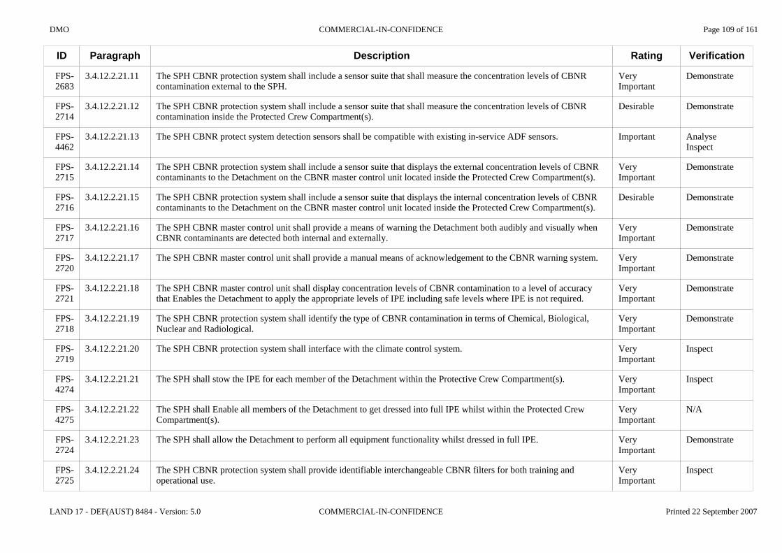
DMO COMMERCIAL-IN-CONFIDENCE Page 109 of 161
LAND 17 - DEF(AUST) 8484 - Version: 5.0 COMMERCIAL-IN-CONFIDENCE Printed 22 September 2007
ID
FPS-2683
FPS-2714
FPS-4462
FPS-2715
FPS-2716
FPS-2717
FPS-2720
FPS-2721
FPS-2718
FPS-2719
FPS-4274
FPS-4275
FPS-2724
FPS-2725
Paragraph
3.4.12.2.21.11
3.4.12.2.21.12
3.4.12.2.21.13
3.4.12.2.21.14
3.4.12.2.21.15
3.4.12.2.21.16
3.4.12.2.21.17
3.4.12.2.21.18
3.4.12.2.21.19
3.4.12.2.21.20
3.4.12.2.21.21
3.4.12.2.21.22
3.4.12.2.21.23
3.4.12.2.21.24
Description
The SPH CBNR protection system shall include a sensor suite that shall measure the concentration levels of CBNR contamination external to the SPH.
The SPH CBNR protection system shall include a sensor suite that shall measure the concentration levels of CBNR contamination inside the Protected Crew Compartment(s).
The SPH CBNR protect system detection sensors shall be compatible with existing in-service ADF sensors.
The SPH CBNR protection system shall include a sensor suite that displays the external concentration levels of CBNR contaminants to the Detachment on the CBNR master control unit located inside the Protected Crew Compartment(s).
The SPH CBNR protection system shall include a sensor suite that displays the internal concentration levels of CBNR contaminants to the Detachment on the CBNR master control unit located inside the Protected Crew Compartment(s).
The SPH CBNR master control unit shall provide a means of warning the Detachment both audibly and visually when CBNR contaminants are detected both internal and externally.
The SPH CBNR master control unit shall provide a manual means of acknowledgement to the CBNR warning system.
The SPH CBNR master control unit shall display concentration levels of CBNR contamination to a level of accuracy that Enables the Detachment to apply the appropriate levels of IPE including safe levels where IPE is not required.
The SPH CBNR protection system shall identify the type of CBNR contamination in terms of Chemical, Biological, Nuclear and Radiological.
The SPH CBNR protection system shall interface with the climate control system.
The SPH shall stow the IPE for each member of the Detachment within the Protective Crew Compartment(s).
The SPH shall Enable all members of the Detachment to get dressed into full IPE whilst within the Protected Crew Compartment(s).
The SPH shall allow the Detachment to perform all equipment functionality whilst dressed in full IPE.
The SPH CBNR protection system shall provide identifiable interchangeable CBNR filters for both training and operational use.
Rating
Very Important
Desirable
Important
Very Important
Desirable
Very Important
Very Important
Very Important
Very Important
Very Important
Very Important
Very Important
Very Important
Very Important
Verification
Demonstrate
Demonstrate
AnalyseInspect
Demonstrate
Demonstrate
Demonstrate
Demonstrate
Demonstrate
Demonstrate
Inspect
Inspect
N/A
Demonstrate
Inspect

DMO COMMERCIAL-IN-CONFIDENCE Page 110 of 161
LAND 17 - DEF(AUST) 8484 - Version: 5.0 COMMERCIAL-IN-CONFIDENCE Printed 22 September 2007
ID
FPS-2726
FPS-2727
FPS-589
FPS-1139
FPS-1141
FPS-2529
FPS-1750
FPS-2486
FPS-4276
FPS-1752
FPS-2485
FPS-1753
FPS-1754
Paragraph
3.4.12.2.21.25
3.4.12.2.21.26
3.4.12.2.21.27
3.4.12.2.22
3.4.12.2.22.1
3.4.12.2.22.2
3.4.12.2.23
3.4.12.2.23.1
3.4.12.2.23.2
3.4.12.2.23.3
3.4.12.2.23.4
3.4.12.2.23.5
3.4.12.2.23.6
Description
The SPH CBNR protection system shall provide identifiable interchangeable CBNR filters that can be changed by a member of the Detachment.
The SPH CBNR master control unit shall provide a means of displaying when the CBNR filters require changing.
The SPH shall be Able to withstand the materiel damaging effects of:a. CBNR contamination;b. CBNR decontaminants; andc. standard CBNR decontamination procedures.
3.4.12.2.22 Self Recovery
The SPH shall be fitted with self recovery equipment.
The SPH's self recovery equipment shall comply with the applicable sections of DEF(AUST) 5684.
3.4.12.2.23 Recovery / Flat Towing
The SPH shall be Able to safely Flat Tow another SPH for at least 5 km at an maximum speed of not less than 20 km/h on Cross Country, Second Class Roads and First Class Roads using only the items in the Standard Equipment List for the SPH.
The total time required to prepare the SPH for flat towing shall not exceed 5 minutes.
The SPH shall be Able to be towed by a recovery vehicle for at least 50 km at an average speed of not less than 25 km/h on sealed and unsealed roads.
Preparation by the Detachment of the SPH for towing by a recovery vehicle shall not exceed 5 minutes.
Whilst under tow, the brake system of the SPH shall be controlled and actuated by the towing vehicle using an interconnection that is part of the Standard Equipment List of the SPH.
Whilst under tow, the brake, indicator, marker and number plate illumination lamps of the SPH shall be controlled and actuated by the towing vehicle using an electrical interconnection cable that is part of the Standard Equipment List of the SPH.
Rating
Very Important
Very Important
Very Important
N/A
Desirable
Very Important
N/A
Important
Important
Very Important
Important
Desirable
Desirable
Verification
Demonstrate
Demonstrate
Test
N/A
Conformance Statement
Conformance Statement
N/A
Demonstrate
Demonstrate
Demonstrate
Demonstrate
Demonstrate
Demonstrate
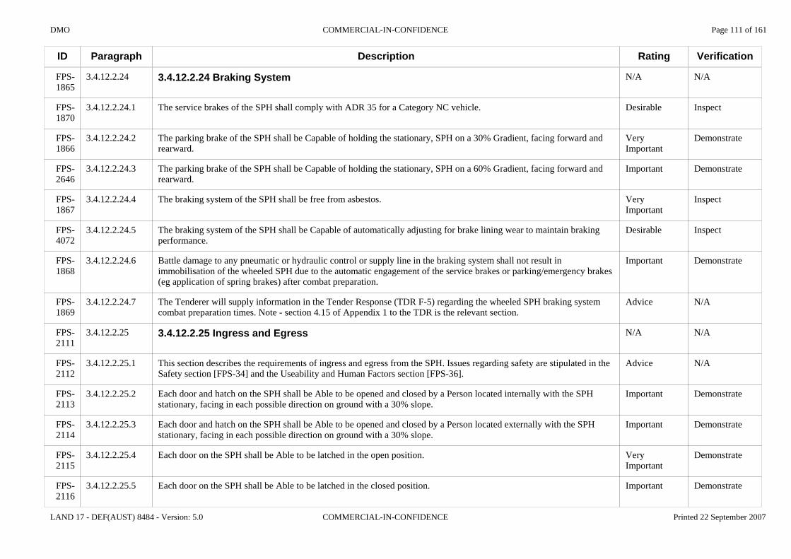
DMO COMMERCIAL-IN-CONFIDENCE Page 111 of 161
LAND 17 - DEF(AUST) 8484 - Version: 5.0 COMMERCIAL-IN-CONFIDENCE Printed 22 September 2007
ID
FPS-1865
FPS-1870
FPS-1866
FPS-2646
FPS-1867
FPS-4072
FPS-1868
FPS-1869
FPS-2111
FPS-2112
FPS-2113
FPS-2114
FPS-2115
FPS-2116
Paragraph
3.4.12.2.24
3.4.12.2.24.1
3.4.12.2.24.2
3.4.12.2.24.3
3.4.12.2.24.4
3.4.12.2.24.5
3.4.12.2.24.6
3.4.12.2.24.7
3.4.12.2.25
3.4.12.2.25.1
3.4.12.2.25.2
3.4.12.2.25.3
3.4.12.2.25.4
3.4.12.2.25.5
Description
3.4.12.2.24 Braking System
The service brakes of the SPH shall comply with ADR 35 for a Category NC vehicle.
The parking brake of the SPH shall be Capable of holding the stationary, SPH on a 30% Gradient, facing forward and rearward.
The parking brake of the SPH shall be Capable of holding the stationary, SPH on a 60% Gradient, facing forward and rearward.
The braking system of the SPH shall be free from asbestos.
The braking system of the SPH shall be Capable of automatically adjusting for brake lining wear to maintain braking performance.
Battle damage to any pneumatic or hydraulic control or supply line in the braking system shall not result in immobilisation of the wheeled SPH due to the automatic engagement of the service brakes or parking/emergency brakes (eg application of spring brakes) after combat preparation.
The Tenderer will supply information in the Tender Response (TDR F-5) regarding the wheeled SPH braking system combat preparation times. Note - section 4.15 of Appendix 1 to the TDR is the relevant section.
3.4.12.2.25 Ingress and Egress
This section describes the requirements of ingress and egress from the SPH. Issues regarding safety are stipulated in the Safety section [FPS-34] and the Useability and Human Factors section [FPS-36].
Each door and hatch on the SPH shall be Able to be opened and closed by a Person located internally with the SPH stationary, facing in each possible direction on ground with a 30% slope.
Each door and hatch on the SPH shall be Able to be opened and closed by a Person located externally with the SPH stationary, facing in each possible direction on ground with a 30% slope.
Each door on the SPH shall be Able to be latched in the open position.
Each door on the SPH shall be Able to be latched in the closed position.
Rating
N/A
Desirable
Very Important
Important
Very Important
Desirable
Important
Advice
N/A
Advice
Important
Important
Very Important
Important
Verification
N/A
Inspect
Demonstrate
Demonstrate
Inspect
Inspect
Demonstrate
N/A
N/A
N/A
Demonstrate
Demonstrate
Demonstrate
Demonstrate

DMO COMMERCIAL-IN-CONFIDENCE Page 112 of 161
LAND 17 - DEF(AUST) 8484 - Version: 5.0 COMMERCIAL-IN-CONFIDENCE Printed 22 September 2007
ID
FPS-2117
FPS-2119
FPS-2118
FPS-4067
FPS-4068
FPS-4069
FPS-4229
Paragraph
3.4.12.2.25.6
3.4.12.2.25.7
3.4.12.2.25.8
3.4.12.2.26
3.4.12.2.26.1
3.4.12.2.26.2
3.4.12.2.26.3
Description
The SPH shall be Able to be Combat Locked by a member of the Detachment located inside the SPH.
At least one door on the SPH shall have the provision for the fitting of an external locking device.
The SPH shall enable the Detachment to egress through at least one exit point (door or hatch) when the SPH is resting on each of the following surfaces:a. on its left hand side;b. on its right hand side; andc. on its roof / turret.
3.4.12.2.26 Stowage of Equipment
Items to be stowed on the SPH are found in Annex A of this Specification. Particular attention should be paid to the information in the columns 'Internal stowage (Y/N/Opt)' and Remarks.
The SPH shall stow all items in accordance with and specified in Table A-1Personnel Equipment Weapons & Rationsand Table A-2 Self Propelled Platform Equipment in Annex A of this Specification.
All items stowed inside the Protected Crew Compartment(s) with a mass greater than 250 g shall remain stowed when subjected to the crash loading: a. in the forward longitudinal direction;b. equivalent to a deceleration from 31 + 1 km/h to 0 km/h; and c. greater than curve ABCD and less than curve EFG as detailed in Figure 3.4.12.2.26-1 Crash Loading.
Rating
Very Important
Important
Important
N/A
Advice
Very Important
Important
Verification
Demonstrate
Demonstrate
Analyse
N/A
N/A
Demonstrate
Analyse

DMO COMMERCIAL-IN-CONFIDENCE Page 113 of 161
LAND 17 - DEF(AUST) 8484 - Version: 5.0 COMMERCIAL-IN-CONFIDENCE Printed 22 September 2007
ID
FPS-4230
FPS-4233
FPS-4231
FPS-4232
FPS-4234
Paragraph
3.4.12.2.26.4
3.4.12.2.26.4.1
3.4.12.2.26.4.2
3.4.12.2.26.5
3.4.12.2.26.5.1
Description
Point Time (ms) Deceleration (g) A 10 0 B 20 8 C 70 8 D 80 0 E 0 12 F 90 12 G 150 0
Note: g = acceleration due to gravity of 9.81 m/s2
Figure 3.4.12.2.26-1 Crash Loading.
All items stowed inside the Protected Crew Compartment(s) with a mass greater than 250 g shall remain stowed when subjected to the crash loading:a. in the left and right lateral direction;b. equivalent to a deceleration from 15.5 + 0.5 km/h to 0 km/h; andc. greater than curve ABCD and less than curve EFG as detailed in Figure 3.4.12.2.26-1, except that the curves shall use the values as specified in Table 3.4.12.2.26-1.
Table 3.4.12.2.26-1 Upper and lower crash loading curve points for side impact
Rating
Important
Important
Important
Important
Important
Verification
Analyse
Analyse
Analyse
Analyse
Analyse

DMO COMMERCIAL-IN-CONFIDENCE Page 114 of 161
LAND 17 - DEF(AUST) 8484 - Version: 5.0 COMMERCIAL-IN-CONFIDENCE Printed 22 September 2007
ID
FPS-4235
FPS-4236
FPS-4237
FPS-4238
FPS-4239
FPS-4240
FPS-4070
FPS-4071
Paragraph
3.4.12.2.26.5.2
3.4.12.2.26.6
3.4.12.2.26.6.1
3.4.12.2.26.6.2
3.4.12.2.26.7
3.4.12.2.26.8
3.4.12.2.26.9
3.4.12.2.26.10
Description
Point Time (ms) Deceleration (g) A 6.5 0 B 13.5 6 C 47 6 D 53.5 0 E 0 9 F 60 9 G 100 0
Note: g = acceleration due to gravity of 9.81 m/s2
All items stowed inside the Protected Crew compartment(s) with a mass greater than 250 g shall remain stowed when subjected to the crash loading:a. in the rear longitudinal, upward vertical and downward vertical directions;b. equivalent to a deceleration from 7.75 + 0.25 km/h to 0 km/h; andc. greater than curve ABCD and less than curve EFG as detailed in Figure 3.4.12.2.26-1, except that the curves shall use the values as specified in Table 3.4.12.2.26-2.
Table 3.4.12.2.26-2: Upper and lower crash loading curve points for up, down and rear impact
Point Time (ms) Deceleration (g) A 5 0 B 10 4 C 35 4 D 40 0 E 0 6 F 45 6 G 75 0
Note: g = acceleration due to gravity of 9.81 m/s2
All parts of item restraint systems shall be securely attached to the SPH.
Placement of items into and removal of items from restraint systems shall not require the use of tools.
All Stowage Bin(s) shall be Able to be locked to prevent unauthorised entry.
Each Stowage Bin shall utilise the same key to lock and unlock.
Rating
Important
Important
Important
Important
Important
Desirable
Important
Important
Verification
Analyse
Analyse
Analyse
Analyse
Inspect
Demonstrate
Demonstrate
Demonstrate

DMO COMMERCIAL-IN-CONFIDENCE Page 115 of 161
LAND 17 - DEF(AUST) 8484 - Version: 5.0 COMMERCIAL-IN-CONFIDENCE Printed 22 September 2007
ID
FPS-1590
FPS-2081
FPS-2082
FPS-2489
FPS-2083
FPS-2084
FPS-2087
FPS-2089
FPS-2687
FPS-2090
FPS-2091
FPS-2092
Paragraph
3.4.12.2.27
3.4.12.2.27.1
3.4.12.2.27.1.1
3.4.12.2.27.1.2
3.4.12.2.27.2
3.4.12.2.27.2.1
3.4.12.2.27.2.1.1
3.4.12.2.27.2.1.2
3.4.12.2.27.2.1.3
3.4.12.2.27.2.1.4
3.4.12.2.27.2.1.5
3.4.12.2.27.2.1.6
Description
3.4.12.2.27 Detachment
3.4.12.2.27.1 General
The SPH shall accommodate and be fully operable and field maintainable by a Detachment of no more than five Personnel for continuous operations.
The SPH shall be operable by a Detachment of no more than three Personnel (including driver) for operations.
3.4.12.2.27.2 Driver
3.4.12.2.27.2.1 Driver's Vision
The driver's vision clauses are for the purposes of mobility and manoeuvrability and will be verified:a. with the driver seated and restrained by a correctly tensioned restraint device in the drivers seated position;b. where a driver's hatch exists it shall be closed unless specified;c. with the driver wearing IPE; andd. with the driver wearing NVG.
The driver's station of the SPH shall provide visibility to enable the driver to safely operate the platform whilst driving in the forward direction.
The SPH shall provide visibility to enable the driver to safely operate the platform whilst driving in the rearward direction aided by:a. rear view vision mirror(s) attached to the exterior of the SPH; b. the commander utilising the commander's visual aid(s); orc. both (a) and (b) as stated above.
The SPH shall provide visibility through a horizontal arc of no less than 180 degrees, with the centre of the arc aligned with the longitudinal centreline of the SPH with the driver's hatch open.
When on level ground, the SPH shall provide the driver direct visibility of the ground at all distances 5 m from the front of the SPH.
When on level ground, the SPH shall provide the driver upward visibility extending to greater than 15 degrees above the horizontal plane level with the drivers eye height throughout the horizontal arc of vision with the driver's hatch open.
Rating
N/A
N/A
Essential
Desirable
N/A
N/A
Advice
Very Important
Important
Important
Important
Important
Verification
N/A
N/A
Demonstrate
Demonstrate
N/A
N/A
N/A
Demonstrate
Demonstrate
Demonstrate
Demonstrate
Demonstrate

DMO COMMERCIAL-IN-CONFIDENCE Page 116 of 161
LAND 17 - DEF(AUST) 8484 - Version: 5.0 COMMERCIAL-IN-CONFIDENCE Printed 22 September 2007
ID
FPS-2093
FPS-2094
FPS-2095
FPS-2097
FPS-2460
FPS-2462
FPS-2099
FPS-2693
FPS-2698
FPS-2103
FPS-2085
FPS-2086
FPS-2105
Paragraph
3.4.12.2.27.2.2
3.4.12.2.27.2.2.1
3.4.12.2.27.2.2.2
3.4.12.2.27.2.2.3
3.4.12.2.27.2.2.4
3.4.12.2.27.2.2.5
3.4.12.2.27.2.3
3.4.12.2.27.2.3.1
3.4.12.2.27.2.3.2
3.4.12.2.27.2.3.3
3.4.12.2.27.3
3.4.12.2.27.3.1
3.4.12.2.27.3.1
Description
3.4.12.2.27.2.2 Driver's Instrumentation
The driver's instrumentation clauses will be verified:a. with the driver seated and restrained by a correctly tensioned restraint device in the drivers seated position;b. where a driver's hatch exists it shall be closed unless specified;c. with the driver wearing IPE; andd. with the driver wearing NVG.
All driver's instrumentation of the SPH shall be:a. within the driver's arc of vision and reach; andb. able to be read by the driver in all operating conditions.
The value displayed by all gauges that form the driver's instrumentation of the SPH shall be accurate to within ± 10 % of the actual value.
When operating in the Blackout lighting mode the condition of the engine indicated on the SPH driver's console by the warning lightsshall operate without affecting the operation of NVG by the driver.
When operating in the Blackout lighting mode the horn of the SPH shall be disabled.
3.4.12.2.27.2.3 Driver's Controls
The SPH driver's controls shall include a navigation screen linked to the navigation screen of the layer's display unit.
The SPH driver's controls shall include an automotive master fuse board which displays short circuits or possible faults for the SPHchassis and turret.
In the event of a power steering system Failure, if a power steering system is fitted to the wheeled SPH, the driver shall be Able to safely steer the SPH and bring it to a halt in all terrain and weather conditions.
3.4.12.2.27.3 Commander
The use of a commander's hatch and 360 degrees viewing arc is stipulated in the Defensive Aids section of this Specification.
3.4.12.2.27.3.1 Commander's Vision
Rating
N/A
Advice
Very Important
Important
Important
Important
N/A
Desirable
Very Important
Very Important
N/A
Advice
N/A
Verification
N/A
N/A
Demonstrate
Analyse
Demonstrate
Demonstrate
N/A
Inspect
Demonstrate
Demonstrate
N/A
N/A
N/A

DMO COMMERCIAL-IN-CONFIDENCE Page 117 of 161
LAND 17 - DEF(AUST) 8484 - Version: 5.0 COMMERCIAL-IN-CONFIDENCE Printed 22 September 2007
ID
FPS-2106
FPS-2108
FPS-2109
FPS-2110
FPS-2473
FPS-2474
FPS-2475
FPS-3519
FPS-26
FPS-1526
FPS-27
FPS-2431
FPS-1524
Paragraph
3.4.12.2.27.3.1.1
3.4.12.2.27.3.1.2
3.4.12.2.27.3.1.3
3.4.12.2.27.3.1.4
3.4.12.2.28
3.4.12.2.28.1
3.4.12.2.28.2
3.4.12.2.28.3
3.5
3.5.1
3.6
3.6.1
3.6.1.1
Description
The commander's vision clauses are for the purposes of mobility and manoeuvrability and will be verified:a. with the commander wearing IPE; andb. with the commander wearing NVG.
When on level ground, the SPH shall provide the commander direct visibility of the ground at all distances 15 m and beyond the front and rear of the SPH when operating with the commander's head protruding from the open commander's hatch irrespective of the orientation of the ordnance.
When on level ground, the SPH shall provide the commander direct visibility of the ground at all distances 5 m and beyond both sides of the SPH when operating with the commander's head protruding from the open commander's hatch.
The commander shall have visibility of + 15 degrees and - 15 degrees from the horizontal plane through a 360 degree arc parallel with the ground with the commander's hatch closed.
3.4.12.2.28 Integrated Sensors
The SPH shall have an integrated muzzle velocity measurement sensor system that is fully integrated into the on-board weapon management system.
The SPH shall have provision for the integration of a vehicle mounted version of a GFE Battle Management System.
The SPH shall be Able to integrate an external sensor to detect CBNR threats in the immediate vicinity of the SPH.
3.5 Availability
Data from the Preferred Tenderer's response to TDID-ILS-DES-TSAD and TDID-ILS-RAM-TRAMD will be incorporated into this section at Contract negotiation to form the availability requirements.
3.6 Reliability
3.6.1 General
Mission essential functions for LAND 17 are defined in the OSCD.Life units of MTBCF and MTBF for LAND 17 are kilometres, hours and rounds.Data from the Preferred Tenderer's response to TDID-ILS-DES-LSAD and TDID-ILS-RAM-TRAMD will be incorporated into this section at Contract negotiation to form the reliability requirements.
Rating
Advice
Important
Important
Important
N/A
Very Important
Very Important
Important
N/A
Advice
N/A
N/A
Advice
Verification
N/A
Analyse
Analyse
Demonstrate
N/A
Demonstrate
Inspect
Test
N/A
N/A
N/A
N/A
N/A

DMO COMMERCIAL-IN-CONFIDENCE Page 118 of 161
LAND 17 - DEF(AUST) 8484 - Version: 5.0 COMMERCIAL-IN-CONFIDENCE Printed 22 September 2007
ID
FPS-2432
FPS-2434
FPS-2435
FPS-2433
FPS-2436
FPS-2437
FPS-28
FPS-2423
FPS-1525
FPS-2424
FPS-2425
FPS-2438
FPS-2449
Paragraph
3.6.2
3.6.2.1
3.6.2.2
3.6.3
3.6.3.1
3.6.3.2
3.7
3.7.1
3.7.1.1
3.7.2
3.7.2.1
3.7.2.1.1
3.7.2.1.2
Description
3.6.2 Basic Reliability
The LAND 17 system, not including any GFE or specialist equipment, shall achieve a Reliability level of TBD%.
The Mean Time Between Failure (MTBF) shall be demonstrated at a 90% lower confidence limit when operated in accordance with the OSCD as defined in Part B to Annex A to SOW including the environmental and climatic conditions as defined in the Environmental Conditions Section [FPS-31] of this specification.
3.6.3 Mission Reliability
The LAND 17 system, not including any GFE or specialist equipment, shall achieve a Mission Reliability level of
The Mean Time Between Critical Failure (MTBCF) shall be demonstrated at a 90% lower confidence limit when operated in accordance with the OSCD as defined in Part B to Annex A to SOW including the environmental and climatic conditions as defined in the Environmental Conditions Section [FPS-31] of this specification.
3.7 Maintainability
3.7.1 General
Data from the Preferred Tenderer's response to TDID-ILS-DES-TSAD and TDID-ILS-RAM-TRAMD will be incorporated into this section at Contract negotiation to form the maintainability requirements.
3.7.2 Corrective Maintenance
3.7.2.1 Operator Corrective Maintenance
Operator level maintenance is maintenance performed by trained and qualified Operators both in barracks and deployed (in Area of Operations or training). Operator level maintenance is predominantly preventative maintenance but includes some basic corrective maintenance.
The LAND 17 system shall have a 90% upper confidence limit Mean Time to Repair (MTTR) of not more than TBDhours for Operator Repairs.
Rating
N/A
Important
Important
N/A
Important
Important
N/A
N/A
Advice
N/A
N/A
Advice
Important
Verification
N/A
DemonstrateAnalyse
DemonstrateAnalyse
N/A
DemonstrateAnalyse
DemonstrateAnalyse
N/A
N/A
N/A
N/A
N/A
N/A
DemonstrateAnalyse
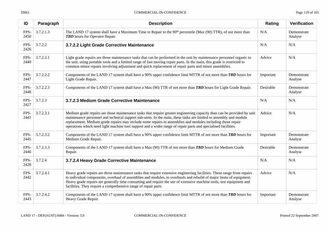
DMO COMMERCIAL-IN-CONFIDENCE Page 119 of 161
LAND 17 - DEF(AUST) 8484 - Version: 5.0 COMMERCIAL-IN-CONFIDENCE Printed 22 September 2007
ID
FPS-2450
FPS-2426
FPS-2440
FPS-2447
FPS-2448
FPS-2427
FPS-2441
FPS-2445
FPS-2446
FPS-2428
FPS-2442
FPS-2443
Paragraph
3.7.2.1.3
3.7.2.2
3.7.2.2.1
3.7.2.2.2
3.7.2.2.3
3.7.2.3
3.7.2.3.1
3.7.2.3.2
3.7.2.3.3
3.7.2.4
3.7.2.4.1
3.7.2.4.2
Description
The LAND 17 system shall have a Maximum Time to Repair to the 90th percentile (Max (90) TTR), of not more than TBD hours for Operator Repair.
3.7.2.2 Light Grade Corrective Maintenance
Light grade repairs are those maintenance tasks that can be performed in the unit by maintenance personnel organic to the unit, using portable tools and a limited range of fast moving repair parts. In the main, this grade is restricted to common minor repairs involving adjustment and quick replacement of repair parts and minor assemblies.
Components of the LAND 17 system shall have a 90% upper confidence limit MTTR of not more than TBD hours for Light Grade Repair.
Components of the LAND 17 system shall have a Max (90) TTR of not more than TBD hours for Light Grade Repair.
3.7.2.3 Medium Grade Corrective Maintenance
Medium grade repairs are those maintenance tasks that require greater engineering capacity than can be provided by unit maintenance personnel and technical support sub-units. In the main, these tasks are limited to assembly and modulereplacement. Medium grade repairs may include some repairs to assemblies and modules including those repair operations which need light machine tool support and a wider range of repair parts and specialised facilities.
Components of the LAND 17 system shall have a 90% upper confidence limit MTTR of not more than TBD hours for Medium Grade Repair.
Components of the LAND 17 system shall have a Max (90) TTR of not more than TBD hours for Medium Grade Repair.
3.7.2.4 Heavy Grade Corrective Maintenance
Heavy grade repairs are those maintenance tasks that require extensive engineering facilities. These range from repairs to individual components, overhaul of assemblies and modules, to overhauls and rebuild of major items of equipment. Heavy grade repairs are generally time consuming and require the use of extensive machine tools, test equipment and facilities. They require a comprehensive range of repair parts
Components of the LAND 17 system shall have a 90% upper confidence limit MTTR of not more than TBD hours for Heavy Grade Repair.
Rating
N/A
N/A
Advice
Important
Desirable
N/A
Advice
Important
Desirable
N/A
Advice
Important
Verification
DemonstrateAnalyse
N/A
N/A
DemonstrateAnalyse
DemonstrateAnalyse
N/A
N/A
DemonstrateAnalyse
DemonstrateAnalyse
N/A
N/A
DemonstrateAnalyse

DMO COMMERCIAL-IN-CONFIDENCE Page 120 of 161
LAND 17 - DEF(AUST) 8484 - Version: 5.0 COMMERCIAL-IN-CONFIDENCE Printed 22 September 2007
ID
FPS-2444
FPS-2429
FPS-2430
FPS-29
FPS-3510
FPS-2180
FPS-430
FPS-431
FPS-432
FPS-2534
FPS-2535
FPS-1877
FPS-433
Paragraph
3.7.2.4.3
3.7.3
3.7.3.1
3.8
3.8.1
3.8.1
3.8.1.1
3.8.1.2
3.8.1.3
3.8.2
3.8.2.1
3.8.2.2
3.8.3
Description
Components of the LAND 17 system shall have a Max (90) TTR of not more than TBD hours for Heavy Grade Repair.
3.7.3 Preventative Maintenance
The LAND 17 system shall have a Mean Time Between Preventative Maintenance (MTBPM) of not less than TBDhours.
3.8 Deployability
This section will describe the requirements for those sub-sets and elements of the LAND 17 system that need to be deployed. It will include timing requirements for preparation, set up and pull down (under applicable environmental conditions), packaging requirements, constraints on deployment footprint and any requirements associated with support when deployed.
3.8.1 General
Strategic deployability involves pre-positioning the maximum combat and combat support capability in the time available within the constraints of strategic lift resources. Resource and space utilisation might take priority over battle readiness.
Tactical mobility deploys forces into a potentially hostile environment where the prime determinant is immediate battle readiness.
Land deployability is governed by mobility categories that apply to each type of vehicle. The mobility categories for this Specification are defined in Annex E of this Specification.
3.8.2 AQIS Requirements
The LAND 17 platform shall be Able to be cleaned without Damage to an extent that passes AQIS quarantine inspection for the purposes of decontamination prior to returning from an overseas deployment.
The external surfaces of the LAND 17 platform, with the exception of textile components and seals, shall be Capable of being cleaned using a high pressure water jet of up to 120 bar at a distance of no closer than 0.9 m for a duration of 10 seconds without Damage.
3.8.3 Common Deployability
Rating
Desirable
N/A
Very Important
N/A
Advice
N/A
Advice
Advice
Advice
N/A
Very Important
Important
N/A
Verification
DemonstrateAnalyse
N/A
DemonstrateAnalyse
N/A
N/A
N/A
N/A
N/A
N/A
N/A
Demonstrate
Test
N/A

DMO COMMERCIAL-IN-CONFIDENCE Page 121 of 161
LAND 17 - DEF(AUST) 8484 - Version: 5.0 COMMERCIAL-IN-CONFIDENCE Printed 22 September 2007
ID
FPS-435
FPS-2539
FPS-436
FPS-4217
FPS-1640
FPS-1641
FPS-1642
FPS-4190
FPS-4191
FPS-4192
FPS-1643
FPS-93
FPS-4189
Paragraph
3.8.3.1
3.8.3.2
3.8.3.3
3.8.3.4
3.8.3.5
3.8.3.6
3.8.3.7
3.8.3.7.1
3.8.3.7.2
3.8.3.7.3
3.8.3.8
3.8.4
3.8.4.1
Description
The LAND 17 system shall be Able to be strategically deployed by civil/commercial road transport assets.
The LAND 17 system shall be Able to be strategically deployed by in-service ADF road transport assets.
The LAND 17 system shall be Able to be strategically deployed by civil/commercial rail transport assets within Australia and in accordance with Australian loading regulations.
The LAND 17 system shall not require preparation for strategic deployment by civil/commercial rail transport assets within Australia.
The LAND 17 system shall be Able to be strategically deployed by in-service ADF sea transport assets including:a. RAN Landing Ship Heavy (LSH); andb. RAN Amphibious Transport Ship (LPA).
The LAND 17 system shall be Able to be strategically deployed by the future ADF Amphibious Ship (LHD).
The LAND 17 system shall be Able to be tactically deployed by in-service ADF amphibious transport assets including:
a. RAN Landing Craft Heavy (LCH/LSM);
b. Army Landing Craft (LCM 8); and
c. LPA watercraft.
The LAND 17 system shall be Able to be tactically deployed by ADF and civil/commercial road transport assets.
3.8.4 Self-Propelled Howitzer Deployability
The ADF road transport assets that will deploy the SPH are the:a. Semi-Trailer, Heavy, Tank/Plant Transporter, MC4, Haulmark and Dolly Converter, Heavy, Tank/Plant Transporter, MC4; andb. Heavy Tank Transporter (procured under LAND 907).
Rating
Very Important
Very Important
Very Important
Desirable
Very Important
Very Important
Very Important
Very Important
Desirable
Desirable
Very Important
N/A
Advice
Verification
Demonstrate
Demonstrate
Demonstrate
Analyse
Demonstrate
Demonstrate
Demonstrate
Demonstrate
Demonstrate
Demonstrate
Demonstrate
N/A
N/A

DMO COMMERCIAL-IN-CONFIDENCE Page 122 of 161
LAND 17 - DEF(AUST) 8484 - Version: 5.0 COMMERCIAL-IN-CONFIDENCE Printed 22 September 2007
ID
FPS-1631
FPS-4299
FPS-4300
FPS-4301
FPS-4302
FPS-4303
FPS-1637
FPS-2536
FPS-4064
FPS-1896
FPS-2499
FPS-2502
…
Paragraph
3.8.4.2
3.8.4.2.1
3.8.4.2.2
3.8.4.2.3
3.8.4.2.4
3.8.4.3
3.8.4.4
3.8.4.5
3.8.4.6
3.8.4.7
3.8.4.8
3.8.4.9
Description
The LAND 17 system shall be Capable of deploying at least 2000 km in no more than 4 days:
a. with refuelling;
b. on sealed roads;
c. with no more than 8 hours driving per day; and
d. either self-deploying or on transportation assets provided by the ADF.
The Tenderer will supply information in the Tenderer Response (TDR F-20) to provide the Commonwealth confidence that long distance haulage of the SPH meets the stated requirement.
The SPH shall be Able to self-deploy at least 200 km in no more than 8 hours without refuelling, when travelling Off-Road.
The SPH shall have a range of not less than 300 km when operating on internally carried fuel when travelling on First Class Roads at the SPH cruising speed.
The SPH shall have a range of not less than 700 km when operating on internally carried fuel when travelling on First Class Roads at the SPH cruising speed.
The SPH together with its Detachment, CES, and initial combat load of ammunition and charges, shall be Able to be strategically deployed by a C17 aircraft.
The SPH shall traverse the landing craft ramp obstacle detailed in Figure 3.8.4-1 in the following manner:a. in a forward gear in both the forward and reverse directions; andb. in a reverse gear in both the forward and reverse directions.
Rating
Very Important
Very Important
Very Important
Very Important
Very Important
Advice
Very Important
Very Important
Desirable
Very Important
Very Important
Advice
Verification
Demonstrate
Demonstrate
Demonstrate
Demonstrate
Conformance Statement
N/A
TestConformance Statement
DemonstrateAnalyse
DemonstrateAnalyse
Demonstrate
Demonstrate
N/A

DMO COMMERCIAL-IN-CONFIDENCE Page 123 of 161
LAND 17 - DEF(AUST) 8484 - Version: 5.0 COMMERCIAL-IN-CONFIDENCE Printed 22 September 2007
ID
FPS-2502
FPS-3449
FPS-30
FPS-2181
FPS-1040
FPS-2185
FPS-1041
FPS-95
FPS-31
FPS-2261
Paragraph
3.8.4.9.1
3.9
3.9.1
3.9.1.1
3.9.1.2
3.9.2
3.9.3
3.10
3.10.1
Description
GROUND
15000 mm4750 mm
3700 mm156.5°
154.5°
Figure 3.8.4-1: Landing Craft Ramp Obstacle
3.9 Transportability
3.9.1 General
This section will specify the requirements for the transportability of the various elements and sub-sets of the LAND 17 system in order to permit its employment and logistic support. This will include the identification of any sub-systems or components that will need to be transported but due to their operational characteristics will be unsuitable for normal transportation (e.g. oversize, hazardous, delicate, etc.).
Information from the Preferred Tenderer's Response (TDR F-20) will be incorporated into this section at Contract negotiation to form the transportability requirements.
3.9.2 Common Transportability
3.9.3 Self-Propelled Howitzer Transportability
3.10 Environmental Conditions
3.10.1 Common Environmental Requirements
Rating
Advice
N/A
N/A
Advice
Advice
N/A
N/A
N/A
N/A
Verification
N/A
N/A
N/A
N/A
N/A
N/A
N/A
N/A
N/A

DMO COMMERCIAL-IN-CONFIDENCE Page 124 of 161
LAND 17 - DEF(AUST) 8484 - Version: 5.0 COMMERCIAL-IN-CONFIDENCE Printed 22 September 2007
ID
FPS-463
FPS-470
FPS-469
FPS-4218
FPS-4219
FPS-4220
FPS-4221
FPS-4222
FPS-4223
FPS-4224
FPS-4225
FPS-1686
FPS-1699
Paragraph
3.10.1.1
3.10.1.1.1
3.10.1.1.2
3.10.1.1.2.1
3.10.1.1.2.2
3.10.1.1.2.3
3.10.1.1.2.4
3.10.1.1.2.5
3.10.1.1.2.6
3.10.1.1.2.7
3.10.1.1.2.8
3.10.1.1.3
3.10.1.2
Description
3.10.1.1 Climate
Proof of the climatic capability of the LAND 17 system will be established by either:a. testing in accordance with the relevant sections of DEF(AUST) 5681 and DEF STAN 00-35; orb. the provision of evidence, including test details and results, that equipment of the same build standard has previously successfully undergone equivalent testing and the effects on the LAND 17 system from operations in the following climatic conditions.
The LAND 17 system shall remain safe and be Capable of operating, without Failure attributable to design, in the following environments defined in DEF(AUST) 5168A:
a. A1 - Hot Dry;
b. A2 - Intermediate Hot Dry;
c. B1 - Wet Warm (Australia);
d. B2 - Wet Hot;
e. B3 - Humid Hot Coastal Desert;
f. C0 - Mild Cold;
g. C1 - Intermediate Cold; and
h. C2 - Cold.
The LAND 17 system shall conform to the technical requirements for the preparation and use of materiel in very cold climates of Section 3 of DEF STAN 23-8.
3.10.1.2 Altitude
Rating
N/A
Advice
Very Important
Very Important
Very Important
Very Important
Very Important
Very Important
Very Important
Very Important
Very Important
Important
N/A
Verification
N/A
N/A
Conformance Statement
Conformance Statement
Conformance Statement
Conformance Statement
Conformance Statement
Conformance Statement
Conformance Statement
Conformance Statement
Conformance Statement
Conformance Statement
N/A
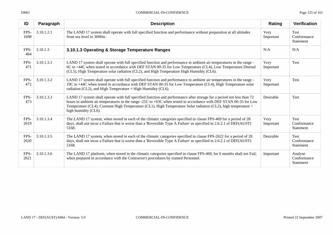
DMO COMMERCIAL-IN-CONFIDENCE Page 125 of 161
LAND 17 - DEF(AUST) 8484 - Version: 5.0 COMMERCIAL-IN-CONFIDENCE Printed 22 September 2007
ID
FPS-1698
FPS-464
FPS-471
FPS-472
FPS-473
FPS-2619
FPS-2620
FPS-2621
Paragraph
3.10.1.2.1
3.10.1.3
3.10.1.3.1
3.10.1.3.2
3.10.1.3.3
3.10.1.3.4
3.10.1.3.5
3.10.1.3.6
Description
The LAND 17 system shall operate with full specified function and performance without preparation at all altitudes from sea level to 3000m.
3.10.1.3 Operating & Storage Temperature Ranges
LAND 17 system shall operate with full specified function and performance in ambient air temperatures in the range -6C to +44C when tested in accordance with DEF STAN 00-35 for Low Temperature (CL4), Low Temperature Diurnal (CL5), High Temperature solar radiation (CL2), and High Temperature High Humidity (CL6).
LAND 17 system shall operate with full specified function and performance in ambient air temperatures in the range -19C to +44C when tested in accordance with DEF STAN 00-35 for Low Temperature (CL4), High Temperature solar radiation (CL2), and High Temperature + High Humidity (CL6).
LAND 17 system shall operate with full specified function and performance after storage for a period not less than 72 hours in ambient air temperatures in the range -21C to +63C when tested in accordance with DEF STAN 00-35 for Low Temperature (CL4), Constant High Temperature (CL1), High Temperature Solar radiation (CL2), high temperature + high humidity (CL6).
The LAND 17 system, when stored in each of the climatic categories specified in clause FPS-469 for a period of 28 days, shall not incur a Failure that is worse than a 'Reversible Type A Failure' as specified in 2.6.2.1 of DEF(AUST) 5168.
The LAND 17 system, when stored in each of the climatic categories specified in clause FPS-2622 for a period of 28 days, shall not incur a Failure that is worse than a 'Reversible Type A Failure' as specified in 2.6.2.1 of DEF(AUST) 5168.
The LAND 17 platform, when stored in the climatic categories specified in clause FPS-469, for 6 months shall not Fail, when prepared in accordance with the Contractor's procedures by trained Personnel.
Rating
Very Important
N/A
Very Important
Very Important
Desirable
Very Important
Desirable
Important
Verification
TestConformance Statement
N/A
Test
Test
Test
TestConformance Statement
TestConformance Statement
AnalyseConformance Statement

DMO COMMERCIAL-IN-CONFIDENCE Page 126 of 161
LAND 17 - DEF(AUST) 8484 - Version: 5.0 COMMERCIAL-IN-CONFIDENCE Printed 22 September 2007
ID
FPS-2297
FPS-2294
FPS-2295
FPS-2296
FPS-3494
FPS-465
Paragraph
3.10.1.3.7
3.10.1.4
3.10.1.4.1
3.10.1.4.2
3.10.1.4.3
3.10.1.5
Description
If the LAND 17 system is to be operated or stored on elevated ground, the temperature conditions for each climatic region shall be adjusted as per the following table:
Climatic Region Ground Elevation above MSL Moderating Factors
A1, A2
B1
B2, B3
Above 900 m
Above 1200 m
Above 1200 m
minus 1°C per 100 m
minus 2°C per 300 m
minus 1°C per 100 m
3.10.1.4 Direct Solar Radiation
Unless moderated by the specific conditions of a particular region of deployment, the LAND 17 system should remain safe and be Capable of acceptable performance when exposed, for the intended duration of deployment, to the levels of solar radiation in the range 0 - 1120 Watts per square metre (W/m2).
Unless moderated by the specific conditions of a particular region of deployment, the LAND 17 system should remain safe and not fail when exposed, for the intended duration of deployment, to the levels of solar radiation in the following table:
Spectral Region Ultra Violet Visible InfraredWavelength (µM) 0.28 - 0.32 0.32 - 0.40 0.40 - 0.52 0.52 - 0.64 0.64 - 0.78 0.78 - 3.00Irradiance (W/m2) 5 63 200 163 174 492
All external plastics, rubbers, polymers and other compounds on the LAND 17 system shall comprise UV degradation inhibitors or shall not Fail when exposed to UV light.
3.10.1.5 Driving Rain
Rating
Advice
N/A
Advice
Advice
Important
N/A
Verification
N/A
N/A
N/A
N/A
AnalyseTestConformance Statement
N/A

DMO COMMERCIAL-IN-CONFIDENCE Page 127 of 161
LAND 17 - DEF(AUST) 8484 - Version: 5.0 COMMERCIAL-IN-CONFIDENCE Printed 22 September 2007
ID
FPS-474
FPS-475
FPS-466
FPS-476
FPS-477…
Paragraph
3.10.1.5.1
3.10.1.5.2
3.10.1.6
3.10.1.6.1
3.10.1.6.2
Description
The LAND 17 system shall not permit water ingress into any system that results in Damage or Degradation when operated in accordance with the published operational mission profiles after being exposed to the following procedure:a. Test Type: Survivalb. Test method: DEF-STAN 00-35 Test CL27c. Configuration: Equipment to be in vehicles and Stowage Bins in normal storage
configuration.d. Test Requirements: No water inside vehicles or Stowage Bins and equipment functional after
test.
The LAND 17 system shall not permit water ingress into any system that results in Damage or Degradation when operated in accordance with the published operational mission profiles after being exposed to the following procedure:a. Test Type: Performanceb. Test method: DEF-STAN 00-35 Test CL27c. Configuration: Equipment deployed for normal operations in exposed weather
conditionsd. Special conditions: Equipment not powered on until commencement of the first
performance test then remains powered until completion ofconditioning.
e. Test Requirements: Performance tests to be commencedi. 30 minutes after commencement of conditioningii. 30 minutes after completion of conditioningiii. Visual inspection after the second performance test.
3.10.1.6 Dust & Sand Exposure
The LAND 17 system shall not permit dust and sand ingress into any system that results in Damage or Degradation when operated in accordance with the published operational mission profiles after being exposed to the following procedure:a. Test Type: Survivalb. Standard: DEF-STAN 00-35c. Test Number: CL25 Dust and sand testd. Severity: Turbulent dust concentration 2 kg/m3e. Duration: Greater than 2 but less than 8 hoursf. Configuration: Transitg. Pass Requirements: Equipment operates with full specified function and performance at the completion of conditioning. No sand inside vehicles or Stowage Bins and equipment functional after test.
The LAND 17 system shall not permit dust and sand ingress into any system that results in Damage or Degradation when operated in accordance with the published operational mission profiles after being exposed to the following procedure:
Rating
Very Important
Very Important
N/A
Very Important
Very Important
Verification
Test
Test
N/A
Test
Test

DMO COMMERCIAL-IN-CONFIDENCE Page 128 of 161
LAND 17 - DEF(AUST) 8484 - Version: 5.0 COMMERCIAL-IN-CONFIDENCE Printed 22 September 2007
ID
FPS-477
FPS-467
FPS-478
FPS-479
FPS-468
FPS-480…
Paragraph
3.10.1.7
3.10.1.7.1
3.10.1.7.2
3.10.1.8
3.10.1.8.1
Description
a. Test Type: Performanceb. Standard: DEF-STAN 00-35c. Test Number: CL25 Dust and sand testd. Severity: Turbulent dust concentration 2 kg/m3, Category 1 (internal heat dissipating) test specimens are connected to a vacuum pump during the teste. Duration: Greater than 2 but less than 8 hoursf. Configuration: Normal deployment condition of equipment operating in exposed weather conditionsg. Pass Requirements: Equipment operates with full specified function and performance during and at the completion of conditioning.
3.10.1.7 Ice Conditions
The LAND 17 system shall not permit ice ingress into any system that results in Damage or Degradation when operated in accordance with the published operational mission profiles after being exposed to the following procedure:a. Test Type: Survivalb. Standard: DEF-STAN 00-35c. Test Number: CL10d. Test Procedure: Procedure Ae. Severity: 'General conditions light loading' in Table 1 CL10, using fresh waterf. Configuration: Transit (in normal storage position)g. Test Requirements: No ice or water inside vehicles or Stowage Bins and equipment functional after test.
The LAND 17 system shall not permit ice ingress into any system that results in Damage or Degradation when operated in accordance with the published operational mission profiles after being exposed to the following procedure:a. Test Type: Performanceb. Standard: DEF-STAN 00-35c. Test Number: CL10d. Test Procedure: Procedure Ae. Severity: 'General conditions light loading' in Table 1 CL10, using fresh waterf. Configuration: Normal deployed condition of equipment operating in exposed weather conditionsg. Test Requirements: Equipment operates with full specified function and performance during and after the test.
3.10.1.8 Shock & Vibration
LAND 17 system mission critical items shall perform with full specified function and performance after being subjected to basic vibration testing in accordance with the following:a. Test Spec: DEF-STAN 00-35
Rating
N/A
Very Important
Very Important
N/A
Very Important
Verification
N/A
Test
Test
N/A
TestConformance Statement

DMO COMMERCIAL-IN-CONFIDENCE Page 129 of 161
LAND 17 - DEF(AUST) 8484 - Version: 5.0 COMMERCIAL-IN-CONFIDENCE Printed 22 September 2007
ID
FPS-480
FPS-481
FPS-482
FPS-483…
Paragraph
3.10.1.8.2
3.10.1.8.3
3.10.1.8.4
Description
b. Test: M1 - Basic Vibration Testc. Severity:
For Tracked Vehicle Equipment:Level 1 - Applies to equipment indirectly mounted to vehicle structureRandom vibration spectral density 0.1 g2/Hz from 20 to 500 HzLevel 2 - Applies to equipment directly mounted to vehicle structureRandom vibration spectral density 0.1 g2/Hz from 20 to 500 Hz reducing at 6 dB/octave to 2000 Hz
For Wheeled Vehicle Equipment:Random vibration spectral density 0.02 g2/Hz from 20 to 50 Hz reducing at 3 dB/octave to 500 Hz
d. Duration: Two to six hours in each of the three mutually perpendicular axes.e. Configuration: As per the configuration on the combat ready SPHf. Pass requirement: Visual inspection and test of each mission critical item to operate with full specified function and performance.
The SPH shall perform with full specified function and performance after being subjected to vehicle durability testing in accordance with the following:a. Test Spec: ATEA Vehicle Durability Testb. Test: see Annex A to DEF(AUST) 5681c. Severity: MC2 and MC3d. Duration: based upon distance in Annex A to DEF(AUST) 5681e. Pass requirement: Visual inspection and test of SPH and all mission critical sub-systems to operate with full specified function and performance.
The Wheeled LAND 17 system mission critical items shall perform with full specified function and performance after being subjected to wheeled vehicle transportation bounce testing in accordance with the following:a. Test Spec: DEF STAN 00-35;b. Test: M11 - Wheeled Vehicle Transportation Bounce Test;c. Severity: Not Applicable;d. Duration: 60 minutes;e. Configuration: As per the configuration on the combat ready SPH;f. Pass requirement: Visual inspection and test of each mission critical item to operate with full specified function and performance.
LAND 17 system mission critical items shall perform with full specified function and performance after being subjected to shock testing in accordance with the following:a. Test Spec: DEF STAN 00-35;b. Test: M3 - Basic Pulse Shock Test;c. Severity: Half sine shock pulses in accordance with Table VI of DEF(AUST) 5681;
Rating
Very Important
Very Important
Very Important
Verification
Demonstrate
TestConformance Statement
TestConformance Statement

DMO COMMERCIAL-IN-CONFIDENCE Page 130 of 161
LAND 17 - DEF(AUST) 8484 - Version: 5.0 COMMERCIAL-IN-CONFIDENCE Printed 22 September 2007
ID
FPS-483
FPS-484
FPS-1729
FPS-1730
FPS-2262
FPS-32
FPS-2186
FPS-421
FPS-420
Paragraph
3.10.1.8.5
3.10.1.9
3.10.1.9.1
3.10.2
3.11
3.11.1
3.11.1.1
3.11.1.2
Description
d. Duration: All shock pulses of 11msecs duration;e. Configuration As per the configuration on the combat ready SPH;f. Pass requirement Visual inspection and test of each mission critical item to operate with full specified function and performance.
LAND 17 system mission critical items shall perform with full specified function and performance after being subjected to rail impact testing in accordance with the following:a. Test Spec: MIL-STD-810E;b. Test: Method 516.4 Procedure VIII;c. Severity: Not applicable;d. Duration: Not applicable;e. Configuration As per the configuration on the combat ready SPH;f. Pass requirement Visual inspection and test of each mission critical item to operate with full specified function and performance.
3.10.1.9 Biological Growth
All textile materials used in the LAND 17 system shall have a rating of 0 when assessed for fungal growth in accordance with AS 1157.2.
3.10.2 Self-Propelled Howitzer Environmental Requirements
3.11 Electromagnetic Radiation
3.11.1 General
The LAND 17 system will operate and tolerate deployment, transportation and storage without degradation to performance, reliability or maintainability in the range of electromagnetic environments expected in normal field operating conditions, including own vehicle systems’ electromagnetic environment, vehicle to vehicle electromagnetic environment and external complex electromagnetic environments.
Electronic components within the LAND 17 system are defined as parts of a "mission critical system" in MIL-STD-464A terms for the purposes of electromagnetic environmental effects on the basis that failure of these components to perform in the environment in which deployment occurs will significantly reduce the operational capability. These components will often be co-located with existing mission and safety critical systems and are required to operate with no adverse impact on those systems.
Rating
Very Important
N/A
Important
N/A
N/A
N/A
Advice
Advice
Verification
TestConformance Statement
N/A
Test
N/A
N/A
N/A
N/A
N/A

DMO COMMERCIAL-IN-CONFIDENCE Page 131 of 161
LAND 17 - DEF(AUST) 8484 - Version: 5.0 COMMERCIAL-IN-CONFIDENCE Printed 22 September 2007
ID
FPS-2258
FPS-418
FPS-1503
FPS-422
FPS-1500
FPS-423
FPS-1504
FPS-424
FPS-1501
FPS-428
FPS-429
FPS-1505
FPS-1511
Paragraph
3.11.2
3.11.2.1
3.11.2.1.1
3.11.2.1.1.1
3.11.2.1.1.2
3.11.2.1.1.3
3.11.2.1.2
3.11.2.1.2.1
3.11.2.1.2.2
3.11.2.1.2.3
3.11.2.1.2.4
3.11.2.1.3
3.11.2.1.3.1
Description
3.11.2 Common Electromagnetic Radiation Requirements
3.11.2.1 EMC/EW
3.11.2.1.1 Electromagnetic Compatibility
In accordance with the requirements of MIL-STD-461E the LAND 17 system shall operate and tolerate deployment, transport and storage without degradation to performance, reliability or maintainability in the electromagnetic conditions experienced by battlefield equipment in service with the ADF.
The LAND 17 system performance shall not degrade beyond its specified agreed tolerance when subjected to unintentional or intentional electromagnetic emissions at the system and sub-system level of configurations and including configurations when interfaced to other external systems.
Safety and mission critical systems shall operate in accordance with specified performance for each equipment and not exhibit susceptibility effects when subjected to the electric fields generated by co-located radio/ transmitter systems.
3.11.2.1.2 Electromagnetic Emission Control
The electromagnetic emission level for the LAND 17 system shall be categorised as Low Probability of Detection for all modes of operation as part of its Emission Control.
The electromagnetic emission level from the LAND 17 system shall not increase when interfaced to other assets.
The LAND 17 system shall comply with MIL-STD-461E for Army Ground equipment on Radiated and Conducted emissions and Radiated and Conducted Susceptibility.
The LAND 17 system and subsystems including information technology equipment shall meet the requirements of MIL-STD-464A for interoperability with collocated radio transmitters and radar units.
3.11.2.1.3 Electromagnetic Radiation Hazards
The LAND 17 system shall comply with the occupational exposure protection requirements of ARPANSA RPS 3.
Rating
N/A
N/A
N/A
Very Important
Very Important
Very Important
N/A
Important
Important
Very Important
Very Important
N/A
Very Important
Verification
N/A
N/A
N/A
Conformance Statement
Conformance Statement
Test
N/A
Test
Test
Test
AnalyseTest
N/A
Test
DMO COMMERCIAL-IN-CONFIDENCE Page 132 of 161
LAND 17 - DEF(AUST) 8484 - Version: 5.0 COMMERCIAL-IN-CONFIDENCE Printed 22 September 2007
ID
FPS-1506
FPS-426
FPS-427
FPS-1510
FPS-1507
FPS-1508
FPS-1509
FPS-2259
FPS-2187
FPS-2191
FPS-2192
FPS-2193
FPS-33
Paragraph
3.11.2.1.4
3.11.2.1.4.1
3.11.2.1.4.2
3.11.2.1.4.3
3.11.2.1.5
3.11.2.1.5.1
3.11.2.1.5.2
3.11.3
3.11.3.1
3.11.3.1.1
3.11.3.1.2
3.11.3.1.3
3.12
Description
3.11.2.1.4 Electromagnetic Hazards to Ordnance
RF currents or powers induced in 155mm Electrically Explosive Devices (EEDs) in all modes of operation (such as handling loading, transport and storage) shall not exceed levels greater than their published No Fire Threshold, less an Approved safety margin.
The safety margin is a function of how well the system and EED is characterised, and could be as much as 16.5 dB.
The LAND 17 system shall not cause arming and /or detonation of Ordnance internal or external to the platform.
3.11.2.1.5 Electrostatic Discharge
The LAND 17 system shall not malfunction or change operational status during and after being subjected to Electrostatic Discharge (ESD) in accordance with the requirements of AS 61000.4.2, at severity level 4 (i.e. 15 kV).
The LAND 17 system shall tolerate storage and transport without degradation to performance, reliability or maintainability during and after being subjected to ESD in accordance with the requirements of AS 61000.4.2, at severity level 4 (i.e. 15 kV)
3.11.3 Self-Propelled Howitzer Electromagnetic Radiation Requirements
3.11.3.1 TEMPEST
The SPH shall comply with the relevant requirements of ACSI 71(C).
The communications equipment of the SPH shall be fitted to comply with the relevant requirements of ACSI 61(C).
The communications equipment of the SPH shall be fitted such that the TEMPEST emanations do not exceed the limits described in NATO AMSG-784B Vol. 1 when tested in accordance with NATO AMSG-784B Vol. 2.
3.12 Architecture, Growth & Expansion
Rating
N/A
Very Important
Advice
Very Important
N/A
Very Important
Very Important
N/A
N/A
Very Important
Very Important
Important
N/A
Verification
N/A
Test
N/A
Test
N/A
Test
Test
N/A
N/A
Test
Test
Test
N/A

DMO COMMERCIAL-IN-CONFIDENCE Page 133 of 161
LAND 17 - DEF(AUST) 8484 - Version: 5.0 COMMERCIAL-IN-CONFIDENCE Printed 22 September 2007
ID
FPS-2255
FPS-488
FPS-489
FPS-490
FPS-491
FPS-2370
FPS-1482
FPS-2256
FPS-34
FPS-4287
FPS-4286
FPS-4284
FPS-4285
Paragraph
3.12.1
3.12.1.1
3.12.1.1.1
3.12.1.1.2
3.12.1.2
3.12.1.2.1
3.12.1.2.2
3.12.2
3.13
3.13.1
3.13.1-1
3.13.1-2
3.13.1-3
Description
3.12.1 Common Architecture, Growth & Expansion Requirements
3.12.1.1 Computer Hardware Resource Utilisation
The computer operating system, programs and data that form part of the LAND 17 system shall utilise no more than 50% of the available hardware storage resources of each LAND 17 computer platform.
The computer operating system, programs and data that form part of the LAND 17 system shall on average utilise no more than 50% of the available hardware processing resources of each LAND 17 computer platform.
3.12.1.2 Platform Electrical Power Supply
For the purposes of this section, the platform electrical power supply is defined as the electrical generating capacity of the engine at Fast Idle along with the sustainment ability of the batteries when the engine is no longer operating.
When all specified equipment is fitted and operational, the LAND 17 platform electrical power supply shall have not less than 25% spare capacity in order to provide power for future upgrades and modifications.
3.12.2 Self-Propelled Howitzer Architecture, Growth & Expansion Requirements
3.13 Safety
3.13.1 Common Safety
The System Safety Program scope shall be as defined in the LAND 17 Statement of Work. The Commonwealth expects all systems to meet statutory requirements (ie are safe to use) as detailed in the Commonwealth OH&S Act 1991. Both the System Safety Program Plan (SSPP) and the Safety Case Report (SCR) are safety deliverables for this contract. Furthermore, the SSPP and the SCR shall be approved by the Commonwealth.
The Contractor shall conduct an Approved System Safety Program (SSP) that complies with LSD SOP-ENG-08 to prove acceptable safe operation for the intended role, configuration and operating environment of the LAND 17 system.
The Contractor shall develop and deliver a Safety Case Report (SCR) in accordance with the LSD SOP-ENG-08.
Rating
N/A
N/A
Important
Important
N/A
Advice
Important
N/A
N/A
Advice
Advice
Advice
Advice
Verification
N/A
N/A
Analyse
Analyse
N/A
N/A
Analyse
N/A
N/A
N/A
N/A
Analyse
Analyse

DMO COMMERCIAL-IN-CONFIDENCE Page 134 of 161
LAND 17 - DEF(AUST) 8484 - Version: 5.0 COMMERCIAL-IN-CONFIDENCE Printed 22 September 2007
ID
FPS-439
FPS-2232
FPS-1480
FPS-2237
FPS-440
FPS-2229
FPS-2200
FPS-2230
FPS-441
FPS-2209
FPS-1827
FPS-2226
FPS-2210
Paragraph
3.13.2
3.13.2.1
3.13.2.1.1
3.13.2.2
3.13.3
3.13.3.1
3.13.3.1.1
3.13.3.2
3.13.4
3.13.4.1
3.13.4.1.1
3.13.4.2
3.13.4.2.1
Description
3.13.2 Electrical Safety
3.13.2.1 Common Electrical Safety Requirements
Firing circuits which include EEDs shall comply with the electrical safety requirements of STANAG 4368 and sub-clause 13.14 of Part 1of DEF STAN 07-85.
3.13.2.2 Self-Propelled Howitzer Electrical Safety Requirements
3.13.3 Mechanical Safety
3.13.3.1 Common Mechanical Safety Requirements
Areas of operation or maintenance where special protective clothing, tools, or equipment are necessary (e.g. insulated shoes, gloves, suits) shall be specifically identified.
3.13.3.2 Self-Propelled Howitzer Mechanical Safety Requirements
3.13.4 Acoustic Safety
3.13.4.1 General
Personnel are to be provided an acoustical environment which will not cause personnel injury, interfere with voice or any other communications, cause fatigue, or in any other way degrade system effectiveness.
3.13.4.2 Common Acoustic Safety Requirements
3.13.4.2.1 Hazardous Noise
Rating
N/A
N/A
Very Important
N/A
N/A
N/A
Important
N/A
N/A
N/A
Advice
N/A
N/A
Verification
N/A
N/A
Test
N/A
N/A
N/A
Inspect
N/A
N/A
N/A
N/A
N/A
N/A

DMO COMMERCIAL-IN-CONFIDENCE Page 135 of 161
LAND 17 - DEF(AUST) 8484 - Version: 5.0 COMMERCIAL-IN-CONFIDENCE Printed 22 September 2007
ID
FPS-3587
FPS-3500
FPS-3501
FPS-2227
FPS-3497
FPS-2206
FPS-2543
FPS-2212
Paragraph
3.13.4.2.1.1
3.13.4.2.2
3.13.4.2.2.1
3.13.4.3
3.13.4.3.1
3.13.4.3.1.1
3.13.4.3.1.2
3.13.4.3.1.3
Description
The LAND 17 platform shall not generate noise in excess of 85 dBA measured at the ear location of each of the Detachment under the following conditions:a. the LAND 17 platform is stationary;b. auxiliary power units are running;c. all sub-systems required for maintenance and resupply are operating; andd. the Detachment are located within 1 metre of the LAND 17 platform.
3.13.4.2.2 Non-hazardous Noise
Not-used.
3.13.4.3 Self-Propelled Howitzer Acoustic Safety Requirements
3.13.4.3.1 Hazardous Noise
The SPH shall not generate impulse noise in excess of maximum allowable levels prescribed by Curve W in Figure 4-1 (Peak sound pressure levels and B-duration limits for impulse noise) of Requirement 4 of MIL-STD-1474D measured at the ear location of each of the Detachment under the following conditions:a. the SPH is firing any projectile at full charge increment;b. the SPH is battened down; andc. the Detachment are located within the Protected Crew Compartment(s).
The SPH shall not generate impulse noise in excess of maximum allowable levels prescribed by Curve X in Figure 4-1 (Peak sound pressure levels and B-duration limits for impulse noise) of Requirement 4 of MIL-STD-1474D measured at the ear location of each of the Detachment under the following conditions:a. the SPH is firing any projectile at full charge increment;b. the SPH is not battened down; and b. members of the Detachment are wearing hearing protection and are located external to and behind the SPH.
The SPH shall not generate steady state noise in excess of maximum allowable levels prescribed by Category B of Table 1-II (Steady-state noise limits (dBA) for personnel-occupied areas) of Requirement 1 of MIL-STD-1474D for an eight hour period measured at the ear location of each of the Detachment under the following conditions:a. the SPH is battened down;b. the Detachment are located within the Protected Crew Compartment(s); andc. the SPH is traversing the Mobility Categories specified in the Mobility section [FPS-1911] of this Specification.
Rating
Important
N/A
N/A
N/A
N/A
Very Important
Desirable
Very Important
Verification
Test
N/A
N/A
N/A
N/A
Test
Test
Test
DMO COMMERCIAL-IN-CONFIDENCE Page 136 of 161
LAND 17 - DEF(AUST) 8484 - Version: 5.0 COMMERCIAL-IN-CONFIDENCE Printed 22 September 2007
ID
FPS-2211
FPS-2207
FPS-1483
FPS-1136
FPS-2220
FPS-2213
FPS-2221
FPS-4074
FPS-4258
FPS-2544
FPS-2696
FPS-1145
Paragraph
3.13.4.3.2
3.13.4.3.2.1
3.13.4.3.2.2
3.13.5
3.13.5.1
3.13.5.1.1
3.13.5.2
3.13.5.2.1
3.13.5.2.1.1
3.13.5.2.1.2
3.13.5.2.1.3
3.13.5.2.1.4
Description
3.13.4.3.2 Non-hazardous Noise
The Protected Crew Compartment(s) should provide an acceptable acoustical work environment that permits necessary direct (person-to-person) and intercom communication when the SPH is stationary, with or without the main engine running whilst maintaining a state of combat readiness.
Ambient noise within the Protected Crew Compartment(s) shall not exceed 75 dBA Speech Interference Level (SIL) as specified in paragraph 5.8.3.3.1 of MIL-STD-1472F under the following conditions:a. the SPH is stationary with the main engine running;b. the SPH is battened down; andc. all sub-systems that are required for combat readiness are operating.
3.13.5 Fire Safety
3.13.5.1 Common Fire Safety Requirements
Common LAND 17 fire safety requirements will be dealt with by the SSP as defined in the Common Safety section [FPS-4287] of this Specification.
3.13.5.2 Self-Propelled Howitzer Fire Safety Requirements
3.13.5.2.1 General
The Tenderer will provide information in the Tender Response (TDR F-3) regarding the current and any proposed Automatic Fire and Explosion Suppression System to meet the requirements of the Self-Propelled Howitzer Fire Safety Requirements section [FPS-2221] of this Specification.
The engine compartment of the SPH shall be fitted with an automatic fire suppression system that operates without Personnel intervention.
The engine compartment of the SPH shall be fitted with a fire suppression system that can be manually operated by the seated, restrained driver.
Fire resistant materials which do not ignite or are self-extinguishing when tested in accordance with AS 1530.3 shall be used in trim and seat construction on the SPH.
Rating
N/A
Advice
Important
N/A
N/A
Advice
N/A
N/A
Advice
Very Important
Important
Very Important
Verification
N/A
N/A
Test
N/A
N/A
N/A
N/A
N/A
N/A
Test
Inspect
TestConformance Statement

DMO COMMERCIAL-IN-CONFIDENCE Page 137 of 161
LAND 17 - DEF(AUST) 8484 - Version: 5.0 COMMERCIAL-IN-CONFIDENCE Printed 22 September 2007
ID
FPS-1146
FPS-4075
FPS-4162
FPS-2546
FPS-3542
FPS-2547
FPS-4164
FPS-4163
FPS-4166
FPS-4167
FPS-4171
FPS-4168
FPS-4169
FPS-4170
Paragraph
3.13.5.2.1.5
3.13.5.2.2
3.13.5.2.2.1
3.13.5.2.2.1.1
3.13.5.2.2.1.2
3.13.5.2.2.1.3
3.13.5.2.2.1.4
3.13.5.2.2.2
3.13.5.2.2.2.1
3.13.5.2.2.2.2
3.13.5.2.2.2.3
3.13.5.2.2.2.4
3.13.5.2.2.2.5
3.13.5.2.2.2.6
Description
For the purpose of verifying requirement FPS-1145, the fire resistance rating is to be 0,0,0,(<6) for the respective indices in clauses 3.2 to 3.5 of AS 1530.3.
3.13.5.2.2 Automatic Fire and Explosion Suppression System
3.13.5.2.2.1 General
The Protected Crew Compartment(s) of the SPH shall be fitted with an Automatic Fire and Explosion Suppression System (AFESS) that operates without Personnel intervention.
The ammunition and charge Magazines of the SPH shall be fitted with an AFESS that operates without Personnel intervention.
The AFESS shall provide the means of preventing burns injury to members of the Detachment when located in the Protected Crew Compartment(s) in the event of an interior fire.
The AFESS shall comply with the Environmental Compliance Requirements section [FPS-35] of this Specification.
3.13.5.2.2.2 Crew Survivability
The AFESS shall extinguish all flames without repeat-flash.
The AFESS shall prevent all skin burns in excess of second degree burns.
Second degree burns may be considered to occur when exposure temperature less body temperature integrated over 10 seconds exceeds 1316 oC-seconds.
The AFESS shall not cause an overpressure in the vehicle in excess of 20 kPa (2.8psi).
The AFESS suppression agent concentration shall not exceed the Lowest Observed Adverse Level.
After initiation of the AFESS the concentration of the suppression agent acidic content in the Protected Crew Compartment(s) shall not exceed 1000 PPM.
Rating
Advice
N/A
N/A
Very Important
Very Important
Very Important
Important
N/A
Important
Important
Advice
Important
Important
Important
Verification
N/A
N/A
N/A
Test
Test
Test
Analyse
N/A
Test
Test
N/A
Demonstrate
Demonstrate
Analyse

DMO COMMERCIAL-IN-CONFIDENCE Page 138 of 161
LAND 17 - DEF(AUST) 8484 - Version: 5.0 COMMERCIAL-IN-CONFIDENCE Printed 22 September 2007
ID
FPS-4172
FPS-4173
FPS-4178
FPS-4174
FPS-4175
FPS-4176
FPS-4177
FPS-4179
FPS-4180
FPS-4181
FPS-4182
Paragraph
3.13.5.2.2.2.7
3.13.5.2.2.3
3.13.5.2.2.3.1
3.13.5.2.2.3.2
3.13.5.2.2.3.3
3.13.5.2.2.3.4
3.13.5.2.2.3.5
3.13.5.2.2.4
3.13.5.2.2.4.1
3.13.5.2.2.4.2
3.13.5.2.2.4.3
Description
The AFESS shall maintain oxygen levels above 16% within the Protected Crew Compartment(s) during a discharge of the suppression agent.
3.13.5.2.2.3 Sensors
The AFESS shall include sensors installed inside the Protected Crew Compartment(s).
The AFESS sensors shall be Capable of detecting an infrared source at any position within the Protected Crew Compartment(s).
The AFESS sensors shall have a detection threshold capable of detecting a hydrocarbon fuel pan fire, 450 mm diameter at a range of not greater than 1500 mm.
The AFESS sensors shall respond to an infrared source at or less than the threshold value as defined in FPS-4175 in not more than 10 milliseconds.
The AFESS sensors shall not activate a discharge of gas when subjected to:a. direct or reflected sunlight;b. thermal source less than 150 oC;c. a lit cigarette at greater than 25 mm;d. burning match at greater than 100 mm;e. any illuminated internal light;f. external incandescent or arc light directed at the sensor;g. flashlight at all ranges; andh. infrared source eg Night Aiming Device.
3.13.5.2.2.4 Discharge Nozzles
The AFESS shall include discharge nozzles installed inside the Protected Crew Compartment(s).
The AFESS discharge nozzles shall be Capable of discharging fire suppressant in sufficient quantity to all parts of the Protected Crew Compartment(s) where a fire may occur.
The AFESS discharge nozzles shall fully open within 10 milliseconds of receipt of an electrical signal indicating the presence of a fire.
Rating
Important
N/A
N/A
Very Important
Important
Important
Important
N/A
Very Important
Very Important
Very Important
Verification
Analyse
N/A
N/A
Test
Test
Test
Demonstrate
N/A
Inspect
AnalyseConformance Statement
Test

DMO COMMERCIAL-IN-CONFIDENCE Page 139 of 161
LAND 17 - DEF(AUST) 8484 - Version: 5.0 COMMERCIAL-IN-CONFIDENCE Printed 22 September 2007
ID
FPS-4183
FPS-4184
FPS-4185
FPS-4186
FPS-4187
FPS-4188
FPS-1369
FPS-2223
FPS-1371
FPS-2224
FPS-442
FPS-2217
FPS-450
Paragraph
3.13.5.2.2.4.4
3.13.5.2.2.5
3.13.5.2.2.5.1
3.13.5.2.2.5.2
3.13.5.2.2.5.3
3.13.5.2.2.5.4
3.13.6
3.13.6.1
3.13.6.1.1
3.13.6.2
3.13.7
3.13.7.1
3.13.7.1.1
Description
The AFESS discharge system shall be Capable of achieving not less than 8% agent concentration at all points throughout the Protected Crew Compartment(s) within 250 milliseconds of initiation of the discharge.
3.13.5.2.2.5 Control System
The AFESS shall include a control unit located inside the Protected Crew Compartment(s).
The AFESS control unit shall permit a member of the Detachment to isolate the system by removing electrical power, and to manually discharge the system, in the event of a failure of the AFESS.
The AFESS control system shall enable the sensors and discharge system to be armed for automatic operation.
The AFESS control system shall include a means of testing the functionality of the system without discharging the suppressant supply.
3.13.6 Explosive Safety
3.13.6.1 Common Explosive Safety
The SPH shall protect the Detachment from injury in the case of initiation of the charges within the Magazines.
3.13.6.2 Self-Propelled Howitzer Explosive Safety Requirements
3.13.7 Radiation Hazards
3.13.7.1 Common Radiation Hazards Requirements
The exposure of non-ionising radiation to the Detachment, due to emissions from radio equipment located on the LAND 17 system when transmitting simultaneously at the maximum power level, shall not exceed the maximum exposure limits of the ARPANSA standard, Maximum Exposure Levels to Radiofrequency Fields - 3 kHz to 300 GHz for exposure category 'Occupational'.
Rating
Very Important
N/A
Very Important
Very Important
Very Important
Very Important
N/A
N/A
Important
N/A
N/A
N/A
Very Important
Verification
Test
N/A
Inspect
Demonstrate
Demonstrate
Demonstrate
N/A
N/A
Test
N/A
N/A
N/A
Conformance Statement

DMO COMMERCIAL-IN-CONFIDENCE Page 140 of 161
LAND 17 - DEF(AUST) 8484 - Version: 5.0 COMMERCIAL-IN-CONFIDENCE Printed 22 September 2007
ID
FPS-452
FPS-2218
FPS-443
FPS-2214
FPS-453
FPS-2215
FPS-459
FPS-444
FPS-2239
FPS-460
FPS-2253
FPS-445
FPS-2240
Paragraph
3.13.7.1.2
3.13.7.2
3.13.8
3.13.8.1
3.13.8.1.1
3.13.8.2
3.13.8.2.1
3.13.9
3.13.9.1
3.13.9.1.1
3.13.9.2
3.13.10
3.13.10.1
Description
Radio frequency transmissions shall be Capable of being disabled during periods when HERP, HERF, and HERO RADHAZ conditions exist.
3.13.7.2 Self-Propelled Howitzer Radiation Hazards Requirements
3.13.8 Hazardous Substances
3.13.8.1 Common Hazardous Substances Requirements
The LAND 17 system shall not expose the Detachment to concentrations of hazardous substances in excess of the levels specified in NOHSC:10005 (1999).
3.13.8.2 Self-Propelled Howitzer Hazardous Substances Requirements
Material inside the SPH shall not emit toxic fumes to a level that would cause sickness, injury or death to the Detachment for internal temperatures up to and including 50oC for a period of exposure of not less than 30 minutes.
3.13.9 Ozone Depleting Substances
3.13.9.1 Common Ozone Depleting Substances Requirements
The LAND 17 system shall not contain substances listed in Schedule 1 of the Ozone Protection and Synthetic Greenhouse Gas Management Act 1989 except for substances listed in Schedule 1, Part IX - HFCs.
3.13.9.2 Self-Propelled Howitzer Ozone Depleting Substances Requirements
3.13.10 Equipment Handling
3.13.10.1 Common Equipment Handling Requirements
Rating
Very Important
N/A
N/A
N/A
Very Important
N/A
Very Important
N/A
N/A
Very Important
N/A
N/A
N/A
Verification
Demonstrate
N/A
N/A
N/A
Conformance Statement
N/A
AnalyseConformance Statement
N/A
N/A
Conformance Statement
N/A
N/A
N/A

DMO COMMERCIAL-IN-CONFIDENCE Page 141 of 161
LAND 17 - DEF(AUST) 8484 - Version: 5.0 COMMERCIAL-IN-CONFIDENCE Printed 22 September 2007
ID
FPS-461
FPS-2251
FPS-35
FPS-2242
FPS-1037
FPS-1895
FPS-2249
FPS-36
FPS-3511
FPS-873
Paragraph
3.13.10.1.1
3.13.10.2
3.14
3.14.1
3.14.1.1
3.14.1.2
3.14.2
3.15
3.15.1
3.15.1
Description
All LAND 17 equipment and components shall conform to the Manual Handling provisions (Part 5) of the Occupational Health and Safety (Commonwealth Employment) (National Standards) Regulations.
3.13.10.2 Self-Propelled Howitzer Equipment Handling Requirements
3.14 Environmental Compliance Requirements
3.14.1 Common Environmental Compliance Requirements
According to the Defence Environmental Policy each Defence Project will be expected to meet the relevant environmental standards applicable to Defence. Measures should be taken to preclude or limit hazards to the natural environment. This will include the use of hazardous materials, hazardous waste and environmental pollutants in the design and operation of the LAND 17 system. It will also include any specific requirements for recycled, recovered or environmentally-sustainable materials to be used. The Commonwealth environmental legislation of particular relevance to Defence includes:a. Environmental Protection and Biodiversity Conservation (EPBC) Act;b. Hazardous Waste (Regulation of Export and Imports) Act;c. National Environmental Protection Measures (Implementation) Act; andd. Ozone Protection and Synthetic Greenhouse Gas Management Act.
The LAND 17 system shall use materials that can be recycled at the end of the system's life.
3.14.2 Self-Propelled Howitzer Environmental Impact Requirements
3.15 Usability & Human Factors
This section will describe the useability and human factors requirements that are applicable to the LAND 17 system, including any special or unique requirements. Included will be any specified areas, stations or equipments that require specific attention due to the criticality of the tasks to be performed and where human error would be particularly serious.
3.15.1 Common Usability & Human Factors
Rating
Very Important
N/A
N/A
N/A
Advice
Desirable
N/A
N/A
Advice
N/A
Verification
InspectConformance Statement
N/A
N/A
N/A
N/A
Conformance Statement
N/A
N/A
N/A
N/A

DMO COMMERCIAL-IN-CONFIDENCE Page 142 of 161
LAND 17 - DEF(AUST) 8484 - Version: 5.0 COMMERCIAL-IN-CONFIDENCE Printed 22 September 2007
ID
FPS-1878
FPS-1722
FPS-1720
FPS-1691
FPS-874
FPS-4059
FPS-1723
FPS-1724
FPS-1725
FPS-1830
FPS-1825
FPS-1832
Paragraph
3.15.1.1
3.15.1.1.1
3.15.1.1.2
3.15.1.1.3
3.15.2
3.15.2.1
3.15.2.1.1
3.15.2.1.2
3.15.2.1.3
3.15.2.1.4
3.15.2.1.5
3.15.2.1.6
Description
3.15.1.1 General
The LAND 17 system will be operated for extended periods of time (up to at least 12 hours), in all weather conditions, and in all operational scenarios. Operator comfort is an important consideration in order to ensure that Detachment performance is not degraded.
The LAND 17 system shall be Able to be operated by ADF Personnel.
The design of the LAND 17 system shall Enable the Detachment and service Personnel to perform LAND 17 system operation and routine maintenance tasks with no greater than a Low Risk of injury whilst wearing DPCU or Tank Crew Clothing with CVCH or KCH and any combination of the following:a. Cold Weather Clothing;b. Combat Body Armour; andc. IPE.
3.15.2 Self-Propelled Howitzer Usability & Human Factors
3.15.2.1 General
The driver's seat of the SPH shall be adjustable such that any seated, restrained Person can meet the posture requirements for sitting work described in paragraph 4.1.4 of DEF STAN 00-25 (Part 17).
In accordance with section 2, paragraph 7.3.2.25 of DEF STAN 00-25 Part 14/1, all doors and hatches of the SPH shall not require a force of more than 90 N to be applied to the handle in order to lock or unlock the door or hatch.
In accordance with section 2, paragraph 7.3.2.25 of DEF STAN 00-25 Part 14/1, all overhead doors and hatches of the SPH shall not require a force of more than 220 N to be applied to the handle in order to lock or unlock the door or hatch with the platform on all combinations of Gradient or sideslope up to and including the platform's maximum.
Mechanical assistance shall be provided for locking doors and hatches where the force exceeds 220N.
Hatches and doors shall meet the dimensional and whole body clearance requirements of paragraph 5.7.7.2.3 of MIL-STD-1472F.
All Armoured hatches and doors of the SPH shall employ some form of damping in order to control the rate of opening and closing as well as preventing the unintentional closure of the hatch or door.
Rating
N/A
Advice
Very Important
Very Important
N/A
N/A
Important
Important
Important
Important
Important
Important
Verification
N/A
N/A
Conformance Statement
Conformance Statement
N/A
N/A
Test
Test
Test
Demonstrate
Inspect
Inspect

DMO COMMERCIAL-IN-CONFIDENCE Page 143 of 161
LAND 17 - DEF(AUST) 8484 - Version: 5.0 COMMERCIAL-IN-CONFIDENCE Printed 22 September 2007
ID
FPS-2104
FPS-1788
FPS-2688
FPS-4065
FPS-4066
FPS-2689
FPS-2690
FPS-2691
FPS-1828
FPS-1692
FPS-37
FPS-3480
FPS-2243
FPS-3481
Paragraph
3.15.2.1.7
3.15.2.1.8
3.15.2.1.9
3.15.2.1.10
3.15.2.1.11
3.15.2.1.12
3.15.2.1.13
3.15.2.1.14
3.15.2.1.15
3.15.2.1.16
3.16
3.16.1
3.16.1
3.16.1.1
Description
The forces required to operate the steering system on the wheeled SPH shall comply with Table IX of Section 5.4.2.2.5 of MIL-STD-1472F.
The SPH shall have a means of providing boiling water that is fit for human consumption.
The SPH shall have a means of providing cold water that is fit for human consumption.
The SPH shall provide 150 litres of water at a temperature of no greater than 20 oC that is fit for human consumption over a period of 3 days.
The SPH shall be fitted with a water tank for hand washing with not less than 40 litres capacity.
The SPH shall provide a means for the Detachment to utilise the excess water accumulated from the climate control system for the purposes of crew comfort.
The SPH shall provide Protective Padding on all internal surfaces other than the floor at locations of exposed surfaces that would not be normally utilised for the fixture of sub-systems.
Sub-systems in clause FPS-2690 can include radios, MVME, climate control system components, CBNR components etc.
The design of the SPH shall permit Personnel to carry and pass all replenishment items safely onto and into the SPH with Low Risk of injury to the Personnel involved.
Foot and handholds shall be positioned to avoid Personnel having to overstretch in bulky clothing.
3.16 Security & Privacy
Reserved.
3.16.1 Common Security & Privacy Requirements
Reserved.
Rating
Important
Important
Important
Important
Desirable
Desirable
Desirable
Advice
Important
Important
N/A
N/A
N/A
N/A
Verification
Test
InspectConformance Statement
Inspect
Test
Inspect
Demonstrate
Inspect
N/A
Conformance Statement
Conformance Statement
N/A
N/A
N/A
N/A
DMO COMMERCIAL-IN-CONFIDENCE Page 144 of 161
LAND 17 - DEF(AUST) 8484 - Version: 5.0 COMMERCIAL-IN-CONFIDENCE Printed 22 September 2007
ID
FPS-2244
FPS-3482
FPS-38
FPS-3484
FPS-2246
FPS-3485
FPS-2247
FPS-3486
FPS-39
FPS-437
FPS-865
FPS-1051
FPS-4152
FPS-4160
Paragraph
3.16.2
3.16.2.1
3.17
3.17.1
3.17.1
3.17.1.1
3.17.2
3.17.2.1
3.18
3.18.1
3.18.1.1
3.18.1.1.1
3.18.1.1.2
3.18.1.1.3
Description
3.16.2 Self-Propelled Howitzer Security & Privacy Requirements
Reserved.
3.17 Adaptation Requirements
Reserved.
3.17.1 Common Adaptation Requirements
Reserved.
3.17.2 Self-Propelled Howitzer Adaptation Requirements
Reserved.
3.18 Design & Implementation Constraints
3.18.1 Common Design & Implementation Constraints
3.18.1.1 Identifying Markings
When delivered, all LAND 17 system equipment shall have Equipment Labels affixed.
All markings on the LAND 17 platform shall be in the English language only.
All graphical symbols marked on LAND 17 system components shall conform to AS 60417.
Rating
N/A
N/A
N/A
N/A
N/A
N/A
N/A
N/A
N/A
N/A
N/A
Very Important
Very Important
Very Important
Verification
N/A
N/A
N/A
N/A
N/A
N/A
N/A
N/A
N/A
N/A
N/A
Inspect
Inspect
Inspect

DMO COMMERCIAL-IN-CONFIDENCE Page 145 of 161
LAND 17 - DEF(AUST) 8484 - Version: 5.0 COMMERCIAL-IN-CONFIDENCE Printed 22 September 2007
ID
FPS-4076
FPS-4153
FPS-4154
FPS-4155
FPS-4156
FPS-4157
FPS-4158
FPS-4159
FPS-4161
FPS-866
FPS-1588
FPS-1142
Paragraph
3.18.1.1.4
3.18.1.1.5
3.18.1.1.6
3.18.1.1.7
3.18.1.1.8
3.18.1.1.9
3.18.1.1.10
3.18.1.1.11
3.18.1.1.12
3.18.1.2
3.18.1.2.1
3.18.1.3
Description
The minimum detail required for each Equipment Label shall be:a. The NSN of the item or Part number if there is no NSN;b. The Item Name;c. The Manufacturers Serial Number;d. The Model Number;e. The Delivery Date; andf. The Army Registered Number if applicable.
All markings on the exterior surfaces of the LAND 17 platform shall be Black (colour 37038) unless otherwise specified; and comply with APAS 0502/1.
All hazards shall be identified with hazard markings in accordance with AS 1319-1994.
All markings other than hazard markings shall comply with section 5.5 of MIL-STD-1472F.
The word "TIEDOWN" shall be marked in letters greater than 15mm high on, or adjacent to, all tie down points on the LAND 17 platform.
The word "LIFT" shall be marked in letters greater than 15mm high on, or adjacent to, all lifting points on the LAND 17 platform.
"NO-STEP" markings shall be provided when necessary to prevent injury to personnel or damage to equipment.
All electrical receptacles shall be marked with their voltage, phase, and frequency characteristics, as appropriate.
Where applicable, the centre of gravity and the weight of LAND 17 system equipment shall be distinctly marked on the equipment casing and carrying case.
3.18.1.2 Standardisation and Interoperability
All LAND 17 hardware and software that utilises Internet Protocol (IP) for network communications shall in accordance with DIMPI 01/2005, have a defined upgrade path to achieve full IP Version 6 (IPv6) compatibility prior to the year 2013.
3.18.1.3 Construction Constraints
Rating
Important
Important
Very Important
Important
Important
Important
Important
Very Important
Desirable
N/A
Essential
N/A
Verification
Inspect
Inspect
Inspect
Inspect
Test
Test
Inspect
Inspect
Inspect
N/A
Conformance Statement
N/A

DMO COMMERCIAL-IN-CONFIDENCE Page 146 of 161
LAND 17 - DEF(AUST) 8484 - Version: 5.0 COMMERCIAL-IN-CONFIDENCE Printed 22 September 2007
ID
FPS-1143
FPS-1144
FPS-2317
FPS-1693
FPS-1695
FPS-4089
FPS-1872
FPS-4083
FPS-4084
FPS-4085
FPS-4086
FPS-4087
FPS-4088
Paragraph
3.18.1.3.1
3.18.1.3.2
3.18.1.3.3
3.18.1.3.4
3.18.1.3.5
3.18.1.4
3.18.1.4.1
3.18.1.4.2
3.18.1.4.2.1
3.18.1.4.2.2
3.18.1.4.2.3
3.18.1.4.2.4
3.18.1.4.2.5
Description
LAND 17 system equipment shall not have any components made of open cell foam.
LAND 17 system equipment shall not have any components made of wood.
The LAND 17 system shall not have any fastenings made from loop & hook type fasteners.
The LAND 17 system shall be constructed to minimise the build-up of ice and thus avoid the formation of slippery surfaces on hand and footholds when operating in cold weather conditions.
Key systems and components of the LAND 17 system shall be protected from rock strikes and minor collisions.
3.18.1.4 Paints and Finishes
The LAND 17 platform and ordnance shall be painted to match the colours and patterns specified by the Commonwealth.
Unless otherwise indicated, the colours to be used are defined in FED-STD-595B and shall include:
a. Camouflage Green (Olive Drab) (colour 34088);
b. Camouflage Brown (colour 30219);
c. Pilbara Brown (colour 30109);
d. Black (colour 37038); and
e. White (colour 37875).
Rating
Very Important
Very Important
Important
Important
Important
N/A
Very Important
Important
Important
Important
Important
Important
Important
Verification
InspectConformance Statement
InspectConformance Statement
Inspect
Demonstrate
Inspect
N/A
Inspect
TestInspect
TestInspect
TestInspect
TestInspect
TestInspect
TestInspect

DMO COMMERCIAL-IN-CONFIDENCE Page 147 of 161
LAND 17 - DEF(AUST) 8484 - Version: 5.0 COMMERCIAL-IN-CONFIDENCE Printed 22 September 2007
ID
FPS-4090
FPS-4091
FPS-4092
FPS-4093
FPS-4094
FPS-4095
FPS-4096
FPS-4097
FPS-4098
FPS-4099
FPS-4100
FPS-4101
FPS-4102
FPS-4104
Paragraph
3.18.1.4.3
3.18.1.4.4
3.18.1.4.5
3.18.1.4.5.1
3.18.1.4.5.2
3.18.1.4.5.3
3.18.1.4.6
3.18.1.4.6.1
3.18.1.4.6.2
3.18.1.4.6.3
3.18.1.4.7
3.18.1.4.8
3.18.1.4.9
3.18.1.4.9.1
Description
All external and internal metallic surfaces of the LAND 17 platform and external surfaces of the ordnance shall be pre-treated and painted except where an exemption is approved by the Commonwealth.
The method of pre-treatment for all surfaces to be painted shall comply with the method described in APAS 0502.
Ferrous metal surfaces shall be:
a. cleaned with a suitable solvent or alkaline detergent wash (followed by a water wash) to remove any residual oil, grease or wax;
b. pre-treatmented by phosphating or abrasive blast cleaning to Class Sa 2½ (also known as “Near White”) or better in accordance with AS 1627.4; and
c. primed with an epoxy primer complying with APAS 0502/3 or with a suitable commercial multipurpose epoxy primer complying with APAS 0502/5 (DFT 30-50 µm).
Non-ferrous metal surfaces shall be:
a. cleaned with a suitable solvent or alkaline detergent wash (followed by a water wash) to remove any residual oil, grease or wax;
b. pre-treated with an appropriate conversion coating or by abrasive blast cleaning to Class Sa 2½ or better in accordance with AS 1627.4; and
c. primed by the application of epoxy primer complying with APAS 0502/4 or of a suitable commercial multipurpose epoxy primer complying with APAS 0502/5 (DFT 30-50 µm).
Any non-metal surfaces shall be prepared, pre-treated and primed in accordance with APAS 0502/5 according to the manufacturer’s instructions for this surface.
Any non-metal surfaces shall be finished with the appropriate finish-coating in accordance with APAS 0502/1 according to the manufacturer’s instructions for this surface.
Where no manufacturer’s instructions exist, the non-metal surface shall be:
a. solvent wiped, primed with a multipurpose epoxy primer complying with APAS 0502/5 to a DFT of 20-30 µm; and
Rating
Important
Important
Important
Important
Important
Important
Important
Important
Important
Important
Important
Important
Important
Important
Verification
Inspect
Conformance Statement
Conformance Statement
Conformance Statement
Conformance Statement
Conformance Statement
Conformance Statement
Conformance Statement
Conformance Statement
Conformance Statement
Conformance Statement
Conformance Statement
Test
Test

DMO COMMERCIAL-IN-CONFIDENCE Page 148 of 161
LAND 17 - DEF(AUST) 8484 - Version: 5.0 COMMERCIAL-IN-CONFIDENCE Printed 22 September 2007
ID
FPS-4105
FPS-4106
FPS-4107
FPS-4108
FPS-4109
FPS-4110
FPS-4111
FPS-4112
FPS-4113
FPS-4463
FPS-4114
FPS-4115
FPS-4116
FPS-4117
Paragraph
3.18.1.4.9.2
3.18.1.4.10
3.18.1.4.11
3.18.1.4.11.1
3.18.1.4.11.2
3.18.1.4.11.3
3.18.1.4.12
3.18.1.4.12.1
3.18.1.4.12.2
3.18.1.4.12.3
3.18.1.4.13
3.18.1.4.14
3.18.1.4.14.1
3.18.1.4.14.2
Description
b. finished with the appropriate finishing coatings complying with APAS 0502/1.
The exterior paint scheme for the LAND 17 platform and ordnance shall comprise one or two primer coats, two Camouflage Green (Olive Drab) finishing coats, and top coats of disruptive pattern paint.
The primer paints shall comply with one of the following:
a. APAS 0502/3;
b. APAS 0502/4; or
c. APAS 0502/5.
The finishing paints shall be Chemical Agent Resistant (CAR) polyurethane coatings which comply with the following:
a. APAS 0502/1;
b. APAS 0154/10; and
c. DEF(AUST) 8232.
The exterior paint scheme comprising primer and finishing coats shall be applied such that a total DFT of not less than 80µm and not greater than 190µm is achieved in all painted areas.
The exterior paints shall be applied in the following sequence and to the specified thickness:
a. Priming paints - two coats totalling 30-50 µm DFT applied to aluminium or steel substrate;
b. Camouflage Green - two coats totalling 50-70 µm DFT over primer;
Rating
Important
Important
Important
Important
Important
Important
Important
Important
Important
Important
Very Important
Important
Important
Important
Verification
Test
Test
Test
Test
Test
Test
Test
Test
Test
Test
Test
Test
Test
Test

DMO COMMERCIAL-IN-CONFIDENCE Page 149 of 161
LAND 17 - DEF(AUST) 8484 - Version: 5.0 COMMERCIAL-IN-CONFIDENCE Printed 22 September 2007
ID
FPS-4118
FPS-4119
FPS-4120
FPS-4121
FPS-4122
FPS-4123
FPS-4124
FPS-4125
FPS-4126
FPS-4127
FPS-4128
FPS-4129
FPS-4130
FPS-4131
Paragraph
3.18.1.4.14.3
3.18.1.4.14.4
3.18.1.4.14.5
3.18.1.4.15
3.18.1.4.15.1
3.18.1.4.15.2
3.18.1.4.15.3
3.18.1.4.16
3.18.1.4.17
3.18.1.4.18
3.18.1.4.19
3.18.1.4.20
3.18.1.4.21
3.18.1.4.22
Description
c. Camouflage Brown - one or two coats totalling 35-50 µm DFT over Camouflage Green;
d. Black - one or two coats totalling 35-50 µm DFT over Camouflage Green; and
e. Pilbara Brown - one or two coats totalling 35-50 µm DFT over Camouflage Green.
The paint scheme for LAND 17 SPH platform metallic interior surfaces that are not readily visible from outside the platform shall comprise:
a. two primer coats of 30-50 µm DFT complying with APAS 0502/3;
b. one White undercoat of 25-35 µm DFT complying with APAS 0029; and
c. two semi gloss White finishing coats of 50-70 µm DFT complying with APAS 0024/2.
The interior metallic surface paint scheme comprising primer and finishing coats shall be applied such that a total DFT of not less than 105µm and not greater than 155µm is achieved in all painted areas.
The inside of all LAND 17 platform hatches (excluding areas covered with insulation material), and including all hinges and latching mechanisms, shall be painted Camouflage Brown in accordance with APAS 0502/1, with the same preparation, pre-treatment, and priming outlined in the requirements above for the appropriate metal substrate.
Insulation materials applied to the inside of hatches and other areas inside all LAND 17 platforms shall be dark green in colour.
Non metallic interior fittings shall be supplied in a dark colour with low lustre, except where finished in particular colour(s) for a specific purpose.
Black plastic components or components with protective or plated finishes that are not normally painted shall be left unpainted.
All exterior surfaces of the LAND 17 SPH platform that in normal operating or servicing conditions may require personnel to walk upon them shall be covered with a non-slip finish.
The non-slip finish shall have sufficient friction to prevent personnel wearing field boots from accidentally slipping when the surface is wet, muddy or dry.
Rating
Important
Important
Important
Important
Important
Important
Important
Very Important
Important
Important
Desirable
Desirable
Very Important
Very Important
Verification
Test
Test
Test
Test
Test
Test
Test
Test
InspectConformance Statement
Inspect
Inspect
Inspect
Test
DemonstrateAnalyse
DMO COMMERCIAL-IN-CONFIDENCE Page 150 of 161
LAND 17 - DEF(AUST) 8484 - Version: 5.0 COMMERCIAL-IN-CONFIDENCE Printed 22 September 2007
ID
FPS-4132
FPS-1873
FPS-1879
FPS-1880
FPS-1881
FPS-4133
FPS-4134
FPS-4135
FPS-492
FPS-1770
FPS-1586
FPS-1587
FPS-1697
Paragraph
3.18.1.4.23
3.18.1.4.24
3.18.1.4.25
3.18.1.4.26
3.18.1.4.27
3.18.1.5
3.18.1.5.1
3.18.1.5.2
3.18.2
3.18.2.1
3.18.2.1.1
3.18.2.1.2
3.18.2.1.3
Description
The non-slip surface shall have a gloss level less than or equal to the gloss level of the disruptive pattern paint scheme described in APAS 0502/1.
The non-slip finish shall be of sufficient durability to maintain the non-slip performance of the finish for a minimum period of 2 years.
The non-slip finish shall be repairable as a Medium Grade repair task following damage to the finish of a total area of not more than 0.5 m² in any one incident.
The non-slip finish shall not present a safety hazard to maintenance personnel during the repair process, (including removal, preparation and reapplication as applicable).
The non-slip finish shall not present an environmental hazard during the repair process (including removal, preparation, reapplication and disposal as applicable).
3.18.1.5 Painting of Ordnance
The primed external surfaces of the ordnance shall be painted to 25 - 40 µm DFT with an undercoat that complies with APAS 0009.
Ordnance external surfaces shall be finished in Camouflage Green (Olive Drab) enamel to 25 - 40 µm DFT as specified in APAS 0006/1.
3.18.2 Self-Propelled Howitzer Design & Implementation Constraints
3.18.2.1 General
The SPH shall be either:a. right hand drive; orb. centre drive.
The design of the SPH shall Enable the driver to exclusively operate all systems on the SPH other than the main armament.
In the event of a rollover onto the roof or any side, the design and construction of the SPH shall prevent fuel spillage.
Rating
Important
Important
Important
Important
Important
N/A
Important
Important
N/A
N/A
Important
Very Important
Very Important
Verification
Test
Conformance Statement
Demonstrate
Conformance Statement
Conformance Statement
N/A
Test
Test
N/A
N/A
Inspect
Demonstrate
DemonstrateConformance Statement

DMO COMMERCIAL-IN-CONFIDENCE Page 151 of 161
LAND 17 - DEF(AUST) 8484 - Version: 5.0 COMMERCIAL-IN-CONFIDENCE Printed 22 September 2007
ID
FPS-1715
FPS-4057
FPS-1826
FPS-4073
FPS-4056
FPS-4141
FPS-4142
FPS-4143
FPS-4144
FPS-4145
FPS-4146
Paragraph
3.18.2.1.4
3.18.2.1.5
3.18.2.1.6
3.18.2.2
3.18.2.2.1
3.18.2.3
3.18.2.3.1
3.18.2.3.2
3.18.2.3.3
3.18.2.3.3.1
3.18.2.3.3.2
Description
All LAND 17 system batteries located within the SPH shall not emit fumes into the Protected Crew Compartment(s).
Wheeled versions of the SPH shall have the different tyre pressures for all modes of the CTIS applied by decals appropriately placed in one location in lettering not less than 20 mm in height.
Outlets within the Protected Crew Compartment(s) for ventilation, cooling and heating shall be adjustable by members of the Detachment.
3.18.2.2 Identifying Markings
The SPH shall be fitted with an approved metal identification plate marked with the following information:a. Equipment Designation: as advised by the Commonwealth Representative and inserted by the Contractor;b. NSN: as advised by the Commonwealth Representative and inserted by the Contractor;c. CAPO No: as advised by the Commonwealth Representative and inserted by the Contractor;d. Manufacturer's name and address: as advised by the Commonwealth Representative and inserted by the Contractor;e. Manufacturer's Serial No: inserted by Contractor;f. Model No: inserted by Contractor;g. Month and Year delivered to Army: inserted by Contractor;h. Equipment Warranty Expiry Date: inserted by Contractor; andi. Army Registration Number: inserted by Contractor.
3.18.2.3 Instruction and Identification Plates
Instruction and identification plates shall be fitted, in visible locations, to indicate to a trained Operator the essential information for the safe and proper operation of the SPH, including all controls and hazards.
The battery compartments shall have wiring decals indicating the wiring circuit of the batteries.
An Instruction and Servicing Data plate shall be fitted to the inside of the SPH that shall include:
a. the correct title of the LAND 17 SPH platform;
b. the SPH tyre inflation pressures for highway, cross-country, and sand (as applicable) using the format XXX kPa;
Rating
Very Important
Important
Important
N/A
Very Important
N/A
Important
Important
Important
Important
Important
Verification
AnalyseInspect
Inspect
Demonstrate
N/A
Inspect
N/A
Inspect
Inspect
Inspect
Inspect
Inspect
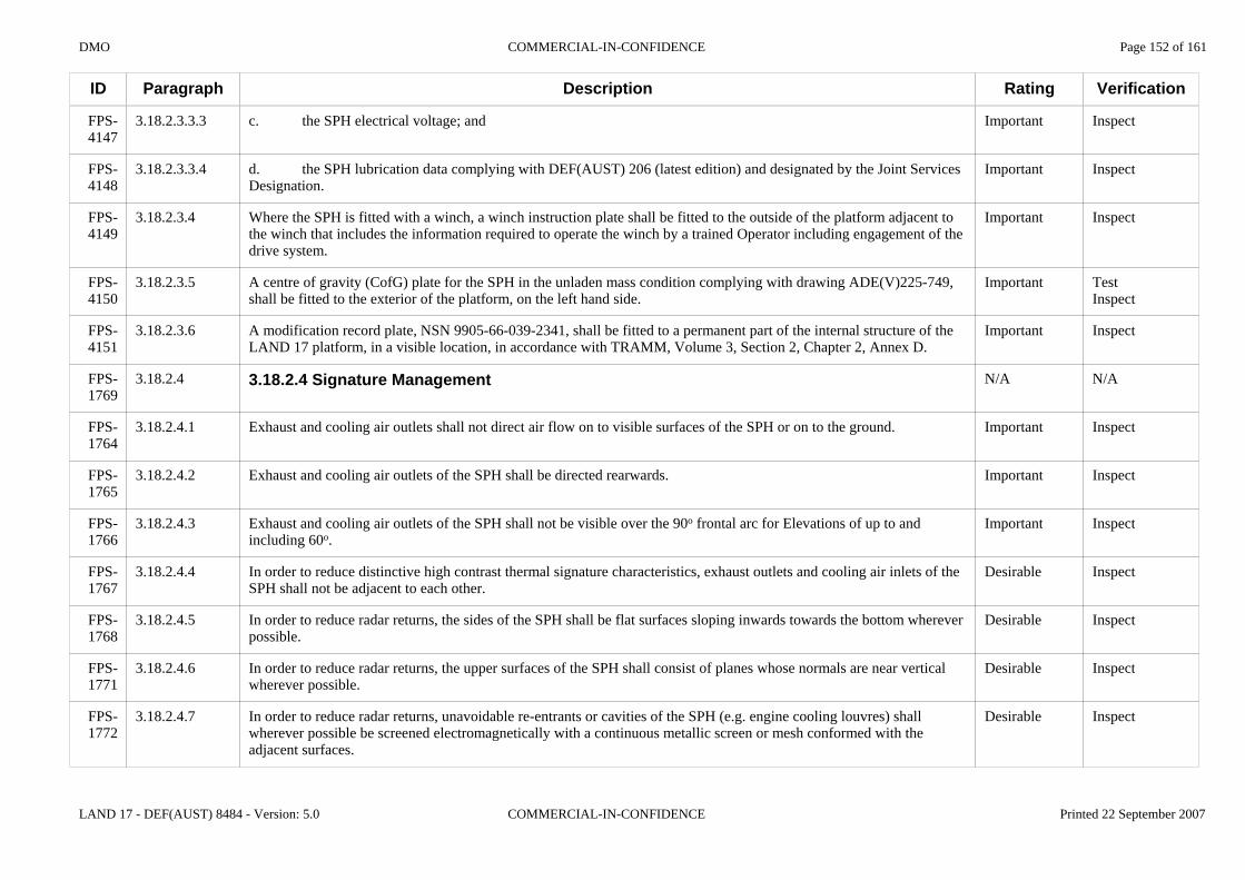
DMO COMMERCIAL-IN-CONFIDENCE Page 152 of 161
LAND 17 - DEF(AUST) 8484 - Version: 5.0 COMMERCIAL-IN-CONFIDENCE Printed 22 September 2007
ID
FPS-4147
FPS-4148
FPS-4149
FPS-4150
FPS-4151
FPS-1769
FPS-1764
FPS-1765
FPS-1766
FPS-1767
FPS-1768
FPS-1771
FPS-1772
Paragraph
3.18.2.3.3.3
3.18.2.3.3.4
3.18.2.3.4
3.18.2.3.5
3.18.2.3.6
3.18.2.4
3.18.2.4.1
3.18.2.4.2
3.18.2.4.3
3.18.2.4.4
3.18.2.4.5
3.18.2.4.6
3.18.2.4.7
Description
c. the SPH electrical voltage; and
d. the SPH lubrication data complying with DEF(AUST) 206 (latest edition) and designated by the Joint Services Designation.
Where the SPH is fitted with a winch, a winch instruction plate shall be fitted to the outside of the platform adjacent to the winch that includes the information required to operate the winch by a trained Operator including engagement of the drive system.
A centre of gravity (CofG) plate for the SPH in the unladen mass condition complying with drawing ADE(V)225-749, shall be fitted to the exterior of the platform, on the left hand side.
A modification record plate, NSN 9905-66-039-2341, shall be fitted to a permanent part of the internal structure of the LAND 17 platform, in a visible location, in accordance with TRAMM, Volume 3, Section 2, Chapter 2, Annex D.
3.18.2.4 Signature Management
Exhaust and cooling air outlets shall not direct air flow on to visible surfaces of the SPH or on to the ground.
Exhaust and cooling air outlets of the SPH shall be directed rearwards.
Exhaust and cooling air outlets of the SPH shall not be visible over the 90o frontal arc for Elevations of up to and including 60o.
In order to reduce distinctive high contrast thermal signature characteristics, exhaust outlets and cooling air inlets of the SPH shall not be adjacent to each other.
In order to reduce radar returns, the sides of the SPH shall be flat surfaces sloping inwards towards the bottom wherever possible.
In order to reduce radar returns, the upper surfaces of the SPH shall consist of planes whose normals are near vertical wherever possible.
In order to reduce radar returns, unavoidable re-entrants or cavities of the SPH (e.g. engine cooling louvres) shall wherever possible be screened electromagnetically with a continuous metallic screen or mesh conformed with the adjacent surfaces.
Rating
Important
Important
Important
Important
Important
N/A
Important
Important
Important
Desirable
Desirable
Desirable
Desirable
Verification
Inspect
Inspect
Inspect
TestInspect
Inspect
N/A
Inspect
Inspect
Inspect
Inspect
Inspect
Inspect
Inspect
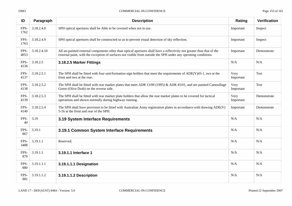
DMO COMMERCIAL-IN-CONFIDENCE Page 153 of 161
LAND 17 - DEF(AUST) 8484 - Version: 5.0 COMMERCIAL-IN-CONFIDENCE Printed 22 September 2007
ID
FPS-1762
FPS-1763
FPS-4053
FPS-4136
FPS-4137
FPS-4138
FPS-4139
FPS-4140
FPS-40
FPS-867
FPS-3488
FPS-879
FPS-880
FPS-881
Paragraph
3.18.2.4.8
3.18.2.4.9
3.18.2.4.10
3.18.2.5
3.18.2.5.1
3.18.2.5.2
3.18.2.5.3
3.18.2.5.4
3.19
3.19.1
3.19.1.1
3.19.1.1
3.19.1.1.1
3.19.1.1.2
Description
SPH optical apertures shall be Able to be covered when not in use.
SPH optical apertures shall be constructed so as to prevent visual detection of sky reflection.
All un-painted external components other than optical apertures shall have a reflectivity not greater than that of the external paint, with the exception of surfaces not visible from outside the SPH under any operating conditions.
3.18.2.5 Marker Fittings
The SPH shall be fitted with four unit/formation sign holders that meet the requirements of ADE(V)43-1, two at the front and two at the rear.
The SPH shall be fitted with rear marker plates that meet ADR 13/00 (1995) & ADR 45/01, and are painted Camouflage Green (Olive Drab) on the reverse side.
The SPH shall be fitted with rear marker plate holders that allow the rear marker plates to be covered for tactical operations and shown normally during highway running.
The SPH shall have provision to be fitted with Australian Army registration plates in accordance with drawing ADE(V)5-16 at the front and rear of the SPH.
3.19 System Interface Requirements
3.19.1 Common System Interface Requirements
Reserved.
3.19.1.1 Interface 1
3.19.1.1.1 Designation
3.19.1.1.2 Description
Rating
Important
Important
Important
N/A
Very Important
Very Important
Very Important
Important
N/A
N/A
N/A
N/A
N/A
N/A
Verification
Inspect
Inspect
Demonstrate
N/A
Test
Test
Demonstrate
Demonstrate
N/A
N/A
N/A
N/A
N/A
N/A

DMO COMMERCIAL-IN-CONFIDENCE Page 154 of 161
LAND 17 - DEF(AUST) 8484 - Version: 5.0 COMMERCIAL-IN-CONFIDENCE Printed 22 September 2007
ID
FPS-982
FPS-983
FPS-3457
FPS-882
FPS-883
FPS-884
FPS-927
FPS-968
FPS-3458
…
Paragraph
3.19.1.1.3
3.19.1.1.3.1
3.19.1.1.3.1.1
3.19.1.2
3.19.1.2.1
3.19.1.2.2
3.19.1.2.3
3.19.1.2.3.1
3.19.1.2.3.1.1
Description
3.19.1.1.3 Definition
Table 3.19-1: Interface 1 definition
Serial Characteristic Name Characteristic Definition ImportanceA Priority B Physical Location C Physical Medium D Communication Medium & Protocols E Type of Interface F Required Data G Capacity Constraints H Security Constraints I Sources & Recipients J Physical Compatibility K Mechanical Constraints
3.19.1.2 Interface 2
3.19.1.2.1 Designation
3.19.1.2.2 Description
3.19.1.2.3 Definition
Table 3.19-2: Interface 2 definition
Rating
N/A
Advice
Advice
N/A
N/A
N/A
N/A
Advice
Advice
Verification
N/A
N/A
N/A
N/A
N/A
N/A
N/A
N/A
N/A

DMO COMMERCIAL-IN-CONFIDENCE Page 155 of 161
LAND 17 - DEF(AUST) 8484 - Version: 5.0 COMMERCIAL-IN-CONFIDENCE Printed 22 September 2007
ID
FPS-3458
FPS-870
FPS-3489
Paragraph
3.19.2
3.19.2.1
Description
Serial Characteristic Name Characteristic Definition ImportanceA Priority B Physical Location C Physical Medium D Communication Medium & Protocols E Type of Interface F Required Data G Capacity Constraints H Security Constraints I Sources & Recipients J Physical Compatibility K Mechanical Constraints
3.19.2 Self-Propelled Howitzer System Interface Requirements
Reserved.
Rating
N/A
N/A
Verification
N/A
N/A

DMO COMMERCIAL-IN-CONFIDENCE Page 156 of 161
LAND 17 - DEF(AUST) 8484 - Version: 5.0 COMMERCIAL-IN-CONFIDENCE Printed 22 September 2007
ID
FPS-41
FPS-1454
FPS-1455
FPS-1456
FPS-1457
FPS-1458
FPS-1459
FPS-1460
Paragraph
4
4.1
4.2
4.2.1
4.2.2
4.2.3
4.2.4
4.2.5
Description
4 PRECEDENCE & CRITICALITY OF REQUIREMENTS
Requirements in this Specification take precedence over requirements specified in any referenced document. Essential requirements take precedence over all other requirements.
All requirements in this Specification have been categorised to define the relative criticality of each requirement to the ADF. The set of categories used is as follows:a. Essential;b. Very Important;c. Important;d. Desirable;e. Advice; andf. To Be Determined.
Essential and ESS. An Essential requirement annotation indicates that the stated requirement shall be met by the tenderer’s proposal. Tenders assessed as not complying with one or more essential requirements will normally be excluded from further evaluation.
Very Important and VIMP. A Very Important requirement annotation indicates that the stated requirements should be met by the tenderer’s proposal. While there is some latitude in meeting the requirement, a major departure from one or more requirements, or a substantial number of minor departures, will represent a significant divergence from the Commonwealth’s requirement. This divergence will reduce the prospect of a proposal being selected as the preferred or compliant tender.
Important and IMP. An Important requirement annotation indicates that the stated requirements should be met by the tenderer’s proposal. While there is some latitude in meeting the requirement, a major departure from one or more requirements, or a substantial number of minor departures, will represent a significant divergence from the Commonwealth’s requirement. This divergence may reduce the prospect of a proposal being selected as the preferred or compliant tender.
Desirable and DES. A Desirable requirement annotation indicates that the stated requirement is perceived by the Commonwealth as beneficial, provided it represents value for money.
Advice and ADV. An Advice annotation indicates that the clause provides advice or information to suppliers. An advice annotation clause does not effect the tender evaluation process.
Rating
N/A
Advice
Advice
Advice
Advice
Advice
Advice
Advice
Verification
N/A
N/A
N/A
N/A
N/A
N/A
N/A
N/A

DMO COMMERCIAL-IN-CONFIDENCE Page 157 of 161
LAND 17 - DEF(AUST) 8484 - Version: 5.0 COMMERCIAL-IN-CONFIDENCE Printed 22 September 2007
ID
FPS-3448
Paragraph
4.2.6
Description
To Be Determined and TBD. A To Be Determined annotation indicates:a. the tenderer's response to this requirement is planned to be used as the basis for the contract version of the FPS; orb. a requirement that is yet to be resolved before contract signature such as the detailed requirements relating to yet-to-be-defined interfaces to future systems.
Rating
Advice
Verification
N/A

DMO COMMERCIAL-IN-CONFIDENCE Page 158 of 161
LAND 17 - DEF(AUST) 8484 - Version: 5.0 COMMERCIAL-IN-CONFIDENCE Printed 22 September 2007
ID
FPS-42
FPS-43
FPS-44
FPS-1461
FPS-1462
FPS-1463
FPS-1464
FPS-1465
FPS-1466
Paragraph
5
5.1
5.2
5.2.1
5.2.2
5.2.3
5.2.4
5.2.5
5.2.6
Description
5 VERIFICATION
5.1 General
5.2 Methods of Verification
Test and VT. A test is the operation of the system, or a part of the system, or equipment using instrumentation or other special test equipment to collect data for later evaluation. The Commonwealth often collects verification test data through the performance of trials. Trials shall be conducted in accordance with the appropriate Test and Evaluation Management Plan.
Demonstrate and VD. A demonstration is the operation of the system, or a part of the system, or equipment, that relies on observable functional operation not requiring the use of instrumentation, special test equipment, or subsequent analysis.
Analyse and VA. Analysis is the processing of accumulated data obtained from other qualification methods or calculations. Examples of analysis include reduction, interpolation, or extrapolation of test results.
Inspect and VI. Inspection is the visual examination of system components, documentation etc.
Conformance Statement and VCS. A conformance statement is a certification issued by either an independent testing authority or a government user, which confirms adherence/compliance to one or more specific requirements and/or standards. This is often done when other methods of verification are not practical, very expensive or not safe to be verified in a realistic environment.
Special and VS. Special means of verification may include the use of special tools or facilities, application of special techniques, procedures, acceptance limits, use of standard samples, pre-production or periodic production samples, pilot models, pilot lots or use of jury panels.
Rating
N/A
N/A
N/A
Advice
Advice
Advice
Advice
Advice
Advice
Verification
N/A
N/A
N/A
N/A
N/A
N/A
N/A
N/A
N/A

DMO COMMERCIAL-IN-CONFIDENCE Page 159 of 161
LAND 17 - DEF(AUST) 8484 - Version: 5.0 COMMERCIAL-IN-CONFIDENCE Printed 22 September 2007
ID
FPS-45
Paragraph
6
Description
6 REQUIREMENTS TRACEABILITY
Rating
N/A
Verification
N/A
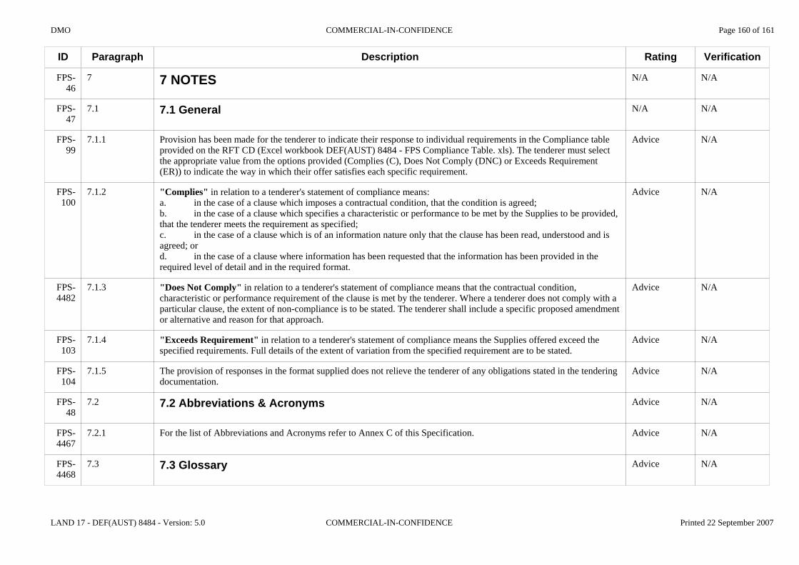
DMO COMMERCIAL-IN-CONFIDENCE Page 160 of 161
LAND 17 - DEF(AUST) 8484 - Version: 5.0 COMMERCIAL-IN-CONFIDENCE Printed 22 September 2007
ID
FPS-46
FPS-47
FPS-99
FPS-100
FPS-4482
FPS-103
FPS-104
FPS-48
FPS-4467
FPS-4468
Paragraph
7
7.1
7.1.1
7.1.2
7.1.3
7.1.4
7.1.5
7.2
7.2.1
7.3
Description
7 NOTES
7.1 General
Provision has been made for the tenderer to indicate their response to individual requirements in the Compliance table provided on the RFT CD (Excel workbook DEF(AUST) 8484 - FPS Compliance Table. xls). The tenderer must select the appropriate value from the options provided (Complies (C), Does Not Comply (DNC) or Exceeds Requirement (ER)) to indicate the way in which their offer satisfies each specific requirement.
"Complies" in relation to a tenderer's statement of compliance means:a. in the case of a clause which imposes a contractual condition, that the condition is agreed;b. in the case of a clause which specifies a characteristic or performance to be met by the Supplies to be provided, that the tenderer meets the requirement as specified;c. in the case of a clause which is of an information nature only that the clause has been read, understood and is agreed; ord. in the case of a clause where information has been requested that the information has been provided in the required level of detail and in the required format.
"Does Not Comply" in relation to a tenderer's statement of compliance means that the contractual condition, characteristic or performance requirement of the clause is met by the tenderer. Where a tenderer does not comply with a particular clause, the extent of non-compliance is to be stated. The tenderer shall include a specific proposed amendment or alternative and reason for that approach.
"Exceeds Requirement" in relation to a tenderer's statement of compliance means the Supplies offered exceed the specified requirements. Full details of the extent of variation from the specified requirement are to be stated.
The provision of responses in the format supplied does not relieve the tenderer of any obligations stated in the tendering documentation.
7.2 Abbreviations & Acronyms
For the list of Abbreviations and Acronyms refer to Annex C of this Specification.
7.3 Glossary
Rating
N/A
N/A
Advice
Advice
Advice
Advice
Advice
Advice
Advice
Advice
Verification
N/A
N/A
N/A
N/A
N/A
N/A
N/A
N/A
N/A
N/A

DMO COMMERCIAL-IN-CONFIDENCE Page 161 of 161
LAND 17 - DEF(AUST) 8484 - Version: 5.0 COMMERCIAL-IN-CONFIDENCE Printed 22 September 2007
ID
FPS-4469
Paragraph
7.3.1
Description
For the Glossary refer to Annex C of this Specification.
Rating
Advice
Verification
N/A