l-2231 ma passport io 11-7-05
TRANSCRIPT
DIRECT EXPANSION SYSTEMS
passport I/O controlsOperation Manual
Revised: 11-7-05L-2231

3 EnglishL-2231
Table of Contents
Copyright 2005 Dometic Environmental Corporation., All Rights Reserved - Every precaution has been taken in the preparation of this manual to insure its accuracy. However, DometicEnvironmental Corporation assumes no responsibility for errors or omissions. Neither is any liability assumed for damages resulting from the use of this product and information contained herein.
1.0 Passport I/O Controls • Introduction 41.01 Standard Features ............................................................................................................................. 41.02 Optional Features ............................................................................................................................... 41.03 Overview............................................................................................................................................. 41.04 Normal Heating or Cooling Cycle ...................................................................................................... 51.05 Reversing Valve Operation ................................................................................................................. 5
2.0 Passport I/O Controls • Basic Operation 62.01 Operator Controls and Display Panel ................................................................................................ 62.02 Dual Button Functions........................................................................................................................ 62.03 Special Button Functions ................................................................................................................... 72.04 Modes of Operation ........................................................................................................................... 72.05 Program Mode.................................................................................................................................... 72.06 Entering Program Mode ..................................................................................................................... 82.07 Restore Memorized Default Settings ................................................................................................. 82.08 Using the Program Mode ................................................................................................................... 82.09 Programming ...................................................................................................................................... 82.10 Failsafe and Mnemonic Fault Handling Codes ................................................................................ 102.11 Quick Start Operations Checklist ..................................................................................................... 11
3.0 Passport I/O Controls • Troubleshooting 123.01 General Troubleshooting .................................................................................................................. 123.02 Digital Controls Troubleshooting ...................................................................................................... 13
4.0 Passport I/O Controls • Maintenance 16Reversing Valves ...................................................................................................................................... 16Seawater Strainer ..................................................................................................................................... 16Condenser Coil Cleaning ......................................................................................................................... 16Return Air Filters ...................................................................................................................................... 16Winterization ............................................................................................................................................. 16
5.0 Passport I/O Controls • Manufacturers Limited Warranty Agreement 17
6.0 Passport I/O Controls • Specifications 18Dimensions ............................................................................................................................................... 18Cable Lengths .......................................................................................................................................... 18System Inputs ........................................................................................................................................... 18Automated Factory Self Test Program ..................................................................................................... 19Service Tools ............................................................................................................................................ 19Display Panel Installation ......................................................................................................................... 19Sample Wiring Diagram............................................................................................................................ 21
Worldwide Dealer Locator 22
4 EnglishL-2231 Introduction
1.0 Passport I/O Controls • Introduction
Passport I/O is a micro controller based unit designed foruse with direct expansion, reverse cycle air conditioningsystems.
1.01 Standard Features• Universal 115/230 volt, 50/60 Hz AC power supply.
• User friendly four button display panel.
• Five volt micro controller located in the display.
• Displays degrees Fahrenheit or degrees Celsius.
• Face plate ambient air sensor.
• 15 programmable parameters.
• High/Low Freon pressure switch inputs.
• Humidity Mode control.
• De-icing cycle prevents evaporator icing.
• Programmable fan operation.
• Programmable compressor delays.
• Nonvolatile memory requiring no backup power.
• Programmable display brightness.
• Programmable fail-safe modes.
1.02 Optional Features• Electric heating control capabilities
• Outside air temperature sensor.
• Alternate air temperature sensor.
This manual provides all necessary information forproper installation and operation of Passport I/O.Poor installation or misunderstood operating parameterswill result in unsatisfactory performance and possiblefailure.
Read This Manual Completely BeforeProceeding !If you have questions, or require assistance with yourPassport I/O control, contact Dometic EnvironmentalCorporation (Dometic).
The Passport I/O is covered under existing Marine AirWarranty Policy. Incorrect installation, neglect andsystem abuse are not covered under Marine Air WarrantyPolicy.
1.03 OverviewPress the Power Button once to engage the system. Thedisplay indicates room temperature when the system ison and is blank when the system is off.
Set the desired room temperature by pressing the Up orDown Button. The set point can be viewed by momen-tarily pressing and releasing the Up or Down Button.
Fan speed operation is automatic allowing fan speed todecrease as room temperature is approached in the CoolMode. The fan will operate at low speed when set pointis satisfied. Manual fan speeds can be selected with theFan Button.
The fan can be programmed to run only when cooling orheating is required. Normally the automatic fan speedoperation is reversed in the Heating Mode, however, thefan can be programmed to operate the same as in theCooling Mode.
Memory: Passport I/O has nonvolatile memory requiringno batteries or backup power. When power is lost theoperating parameters are retained indefinitely. Whenpower is restored, the control resumes operating as lastprogrammed.
IMPORTANT PROGRAMMINGNOTES TO INSTALLER AND ENDUSER:1. If your air conditioning unit is a 24,000 BTU model, or
if it has a High Velocity blower, then you MUSTreprogram parameter P-16 prior to operating equip-ment. A 24K unit is identifiable by the “24” in the modelnumber (i.e., VCD24K). A High Velocity blower doesnot have a blower motor overhang, the motor is insidethe blower, and there is an “HV” in the model number.See the Programming section P-16 for instructions.
2. If your air conditioning unit is Cool Only - if it does nothave a reversing valve - then Cool Only Mode MUSTbe programmed into parameter P-1 (factory default isAutomatic Mode). DO NOT program Automatic Modefor a Cool Only unit. If Automatic Mode is selected andthe thermostat calls for heat, the compressor will run.Since there is no reversing valve, the air conditioningunit will supply cool air when heating is desired. CoolOnly units do not heat. Please see programmableparameter P-1 for more information on how to set theproper operating mode.
5 EnglishL-2231 Introduction
3. When powering on the Passport I/O control, pressand immediately release the Power button so as tonot unintentionally enter Program Mode. ProgramMode will be entered if the Power button is pressedand held for more than 5 seconds. If Program Mode isentered unintentionally, any subsequent presses ofthe Up or Down buttons will change the P-1 param-eter setting since it is the first parameter shown afterentering this mode. This will in turn change theoperating mode to Cool Only, Heat Only, or Automatic,which could result in improper system operation.Please use care when using Program Mode and referto the corresponding sections in this manual forfurther information.
1.04 Normal Heating or CoolingCycleAutomatic heating and cooling will be supplied asrequired. Automatic operation maintains a 2°F (1.1°C)temperature variation. A 4°F (2.2°C) change in tem-perature is required to cause the unit to shift to theopposite mode. Once in Heating or Cooling Mode,Passport I/O will maintain a 2°F (1.1°C) differential.
Program Cool only and cooling only will be supplied.The cabin temperature will be maintained within 2°F(1.1°C) of set point. Program Heat only and heating onlywill be supplied. The cabin temperature will be main-tained within 2°F (1.1°C) of set point.
When the heating or cooling is satisfied, the compressorcycles off and the fan returns to low speed. The fanspeed will remain constant if Manual Fan Speed hasbeen selected.
1.05 Reversing Valve OperationThe reversing valve is toggled to the opposite modewhen heating or cooling is required to reduce thecompressor starting surge. The valve will only toggle tothe opposite mode when a cooling or heating cycle iscalled for and if the system has been off for less than75 seconds. The valve will also toggle if a cycle isinterrupted from the display panel by pressing the PowerButton, or changing the set point. Unnecessary valvetoggling has been limited to reduce reversing valvenoise. Valve toggling can be totally eliminated byprogramming the minimum compressor staging delay at75 seconds or greater (program P-4).
Power On Reset, which occurs when the system ispowered up, will always initiate a valve toggle.
6 EnglishL-2231 Operation
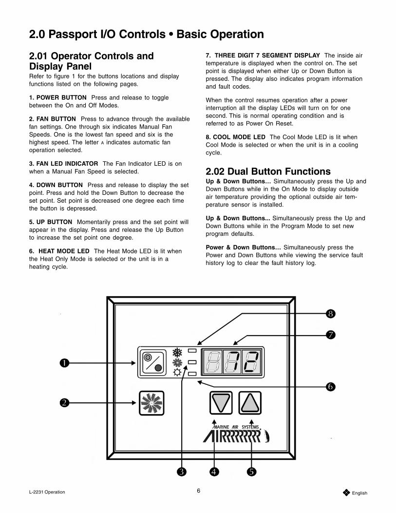
2.01 Operator Controls andDisplay PanelRefer to figure 1 for the buttons locations and displayfunctions listed on the following pages.
1. POWER BUTTON Press and release to togglebetween the On and Off Modes.
2. FAN BUTTON Press to advance through the availablefan settings. One through six indicates Manual FanSpeeds. One is the lowest fan speed and six is thehighest speed. The letter A indicates automatic fanoperation selected.
3. FAN LED INDICATOR The Fan Indicator LED is onwhen a Manual Fan Speed is selected.
4. DOWN BUTTON Press and release to display the setpoint. Press and hold the Down Button to decrease theset point. Set point is decreased one degree each timethe button is depressed.
5. UP BUTTON Momentarily press and the set point willappear in the display. Press and release the Up Buttonto increase the set point one degree.
6. HEAT MODE LED The Heat Mode LED is lit whenthe Heat Only Mode is selected or the unit is in aheating cycle.
7. THREE DIGIT 7 SEGMENT DISPLAY The inside airtemperature is displayed when the control on. The setpoint is displayed when either Up or Down Button ispressed. The display also indicates program informationand fault codes.
When the control resumes operation after a powerinterruption all the display LEDs will turn on for onesecond. This is normal operating condition and isreferred to as Power On Reset.
8. COOL MODE LED The Cool Mode LED is lit whenCool Mode is selected or when the unit is in a coolingcycle.
2.02 Dual Button FunctionsUp & Down Buttons… Simultaneously press the Up andDown Buttons while in the On Mode to display outsideair temperature providing the optional outside air tem-perature sensor is installed.
Up & Down Buttons... Simultaneously press the Up andDown Buttons while in the Program Mode to set newprogram defaults.
Power & Down Buttons… Simultaneously press thePower and Down Buttons while viewing the service faulthistory log to clear the fault history log.
2.0 Passport I/O Controls • Basic Operation
7 EnglishL-2231 Operation
Power & Down Buttons… Simultaneously press thePower and Down Buttons while in the On Mode to enterthe Moisture Mode.
2.03 Special Button FunctionsSpecial button functions are implemented by pressingand holding a particular button while the controls' ACpower is turned on.
1. Service History Log… View the service history log bypressing and holding the Fan Button while turning on theAC power. Exit the service history log by pressing thePower Button once. See the Service History Log section.
2. Self Test Mode… Press and hold the Power Buttonwhile AC power is applied to enter the Self Test Mode.The self test is used to diagnose problems and test theair conditioning system. For complete details see theAutomated Factory Self Test Program section.
3. View Hour Meter… To view the compressor hourmeter, press and hold the Down Button while applyingAC power. Maximum recorded time is 65,536 hours. Thehour meter functions are described fully in the ServiceTools section.
2.04 Modes of OperationOff ModeWhen the Passport I/O is in the Off Mode, all controloutputs are turned off. Program parameters and usersettings are saved in nonvolatile memory. The ProgramMode can only be accessed from the Off Mode.
On ModeWhen the control is in the On Mode power is supplied tothe appropriate outputs and the display indicates thecurrent state of operation. The operating and programparameters resume based on those stored the last timethe unit was operating.
Cooling ModeWhen Cool Mode is selected the cooling systems areoperated as required. When the temperature drops belowthe set point, the system will not automatically switch tothe Heat Mode.
Heat ModeWhen the Heat LED is on, only the heating systems areselected and operated as required. Should the tempera-ture rise above the set point, the system will not auto-matically switch to the Cool Mode.
Automatic ModeAutomatic Mode provides both heating and cooling asrequired. The Heat or Cool LED will be lit according tothe mode required. Temperature in a given mode ismaintained within 2°F (1.1°C) of set point, however a4°F (2.2°C) difference is required to allow the control tochange modes. Once the mode changes temperature willbe maintained within 2°F (1.1°C) of set point.
Manual Fan ModePress and hold the Fan Button during normal operationto select one of the six manual fan speeds available. Thefastest fan speed is represented by “6”, the slowestrepresented by “1”. Manual Fan Mode allows the user toselect the desired fan speed manually. When a manualfan speed has been selected, the fan LED will be lit.Manual Fan Mode is sometimes preferred when roomtemperature is constantly changing due to varying heatloads.
Circulation ModeWhen the system is off at the display panel the fan canbe used to only circulate the air. Press and hold the FanButton when the display is off until the desired speednumber appears in the window. Release the Fan Buttonand the fan will run at the selected speed circulating theair without heating or cooling. Press the Power Buttononce to cancel the Circulation Mode and enter the OnMode.
Moisture ModeWhile in the On Mode simultaneously press the Powerand Down Buttons. The first cycle will start in oneminute. Every four hours, the fan is started and aircirculated for thirty minutes. During this time the airtemperature is sampled and entered into memory. Thecooling cycle is started and continues until the tempera-ture is lowered 2°F (1.1°C). The compressor is allowed amaximum of one hour running time to reach the desiredtemperature. Four hours after the temperature is satisfiedor the compressor times out, the cycle is repeated. The“HU1” mnemonic code is displayed while in the MoistureMode.
Press the Power Button to end the Moisture Mode.
2.05 Program ModeThe Program Mode is used to adjust the systemsoperating parameters to suit the particular needs ofindividual users. The Program Mode is also used to tailorthe air conditioning system for the most efficient opera-tion within an installation. Variables such as, ducting,sensor location and system layout affect the systemoperation. Passport I/O is shipped with factory defaultsettings which are stored in permanent memory and canbe recalled at any time.
8 EnglishL-2231 Operation
2.06 Entering Program ModeThe program mode can only be entered from the OffMode. Press and hold the Power Button while in the OffMode until the letter “P” appears in the display. Thecharacters “P 1” followed by the parameter setting,appear in the display. The Passport I/O control is now inthe Program Mode.
NOTE: The control will exit the Program Mode and returnto the Off Mode if no programming is attempted for oneminute.
2.07 Restore Memorized DefaultSettingsIMPORTANT ! The memorized default settings can berestored by entering the Program Mode and setting P-17to “rSt”. Exit the Program Mode and the software versionnumber (“A12”) appears in the display. The memorizeddefault settings are restored and the Passport I/O controlreturns to the Off Mode.
2.08 Using the Program ModeIncrement from one program parameter to the next bypressing the Fan Button while in the Program Mode.Press and release the Fan Button to advance to thedesired parameter. The programmable parameters rangefrom P-1 through P-17.
Up and Down ButtonsThe Up and Down Buttons are used to select thedata or set the desired limits for the parameter beingprogrammed.
Saving New Program ParametersSimultaneously press the Up and Down Buttons while inthe Program Mode to save the new program parameters.This will also set the new program defaults. Factorydefaults shown in the table may be reset manually.
Exiting the Program ModeThere are two methods to exit the Program Mode. Pressthe Power Button and the control will return to the OffMode. Not pressing any buttons or attempting anyprogram changes for one minute will exit the ProgramMode.
Software IdentificationThe software version of the control is identified for onesecond prior to the exit from the Program Mode. Thesoftware identification number, i.e. (“A12”) will appear inthe display for one second, then the control will return tothe Off Mode.
NOTE:Should there be any reason to contact DometicCorporation about the system or programmingPassport I/O be sure to have the software identifica-tion number and air conditioning unit serial numberavailable. The serial number may be found on thedataplate label.
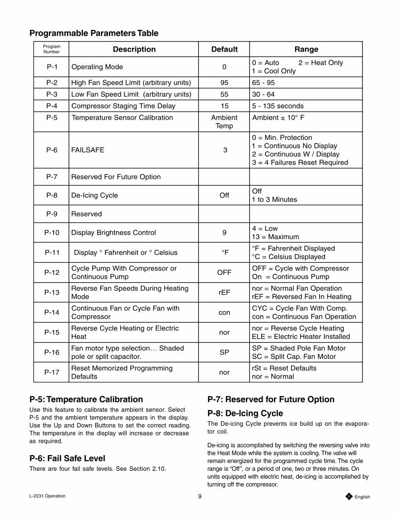
2.09 ProgrammingProgrammable ParametersThere are 15 programmable parameters with theirfactory default settings listed in this section. The follow-ing table indicates what these parameters are, alongwith the permitted values and the original factory defaultsettings.
Should any programming problems or confusionoccur, reset the Memorized Default Settings by enter-ing the program mode and setting P-17 to “rSt”.
P-1: Operating ModeThe following operating modes can be selected: Auto-matic Mode by programming “0”, Cool Mode by selecting“1” and Heat Mode by selecting “2”.
P-2: High Fan LimitThe upper fan speed limit can be adjusted for variousmotors. The high fan limit is adjusted with the systeminstalled and operating. The values range from 65through 95 arbitrary units. Set a higher number for ahigher fan speed. Set lower number to lower the fanspeed. Use the Up and Down Buttons to select thedesired speed.
P-3: Low Fan LimitThe low fan limit determines the lowest output allowed forthe low fan speed. The values from 30 through 64,arbitrary units. Use the Up and Down Buttons to select thelow fan limit. Set a higher number, for higher fan speed.Setting lower numbers lowers the fan speed.
IMPORTANT ! Once the high and low fan speed limitsare set, the unit will automatically readjust the remainingspeeds to produce three equally spaced fan speeds inboth Automatic and Manual Fan Modes.
P-4: Compressor Staging Time DelayThe compressor staging delay is provided for installa-tions where more than one system operates from thesame power source. Setting different staging delaysallows compressors to start at different times whenpower is interrupted. Units should be staged fiveseconds apart. The minimum delay is five seconds andthe maximum is 135 seconds. (See the Reversing ValveOperation section for programming tips.)
9 EnglishL-2231 Operation
P-5: Temperature CalibrationUse this feature to calibrate the ambient sensor. SelectP-5 and the ambient temperature appears in the display.Use the Up and Down Buttons to set the correct reading.The temperature in the display will increase or decreaseas required.
P-6: Fail Safe LevelThere are four fail safe levels. See Section 2.10.
P-7: Reserved for Future Option
P-8: De-Icing CycleThe De-icing Cycle prevents ice build up on the evapora-tor coil.
De-icing is accomplished by switching the reversing valve intothe Heat Mode while the system is cooling. The valve willremain energized for the programmed cycle time. The cyclerange is “Off”, or a period of one, two or three minutes. Onunits equipped with electric heat, de-icing is accomplished byturning off the compressor.
Programmable Parameters TablemargorPrebmuN noitpircseD tluafeD egnaR
1-P edoMgnitarepO 0ylnOtaeH=2otuA=0
ylnOlooC=1
2-P )stinuyrartibra(timiLdeepSnaFhgiH 59 59-56
3-P )stinuyrartibra(timiLdeepSnaFwoL 55 46-03
4-P yaleDemiTgnigatSrosserpmoC 51 sdnoces531-5
5-P noitarbilaCrosneSerutarepmeT tneibmApmeT
F°01±tneibmA
6-P EFASLIAF 3
noitcetorP.niM=0yalpsiDoNsuounitnoC=1yalpsiD/WsuounitnoC=2
deriuqeRteseRseruliaF4=3
7-P noitpOerutuFroFdevreseR
8-P elcyCgnicI-eD ffOffO
setuniM3ot1
9-P devreseR
01-P lortnoCssenthgirByalpsiD 9woL=4
mumixaM=31
11-P suisleC°rotiehnerhaF°yalpsiD F°deyalpsiDtiehnerhaF=F°
deyalpsiDsuisleC=C°
21-ProrosserpmoChtiWpmuPelcyC
pmuPsuounitnoCFFO
rosserpmoChtiwelcyC=FFOpmuPsuounitnoC=nO
31-PgnitaeHgniruDsdeepSnaFesreveR
edoMFEr
noitarepOnaFlamroN=rongnitaeHnInaFdesreveR=FEr
41-PhtiwnaFelcyCronaFsuounitnoC
rosserpmoCnoc
.pmoChtiWnaFelcyC=CYCnoitarepOnaFsuounitnoC=noc
51-PcirtcelErognitaeHelcyCesreveR
taeHron
gnitaeHelcyCesreveR=rondellatsnIretaeHcirtcelE=ELE
61-PdedahS…noitcelesepytrotomnaF
.roticapactilpsroelopPS
rotoMnaFeloPdedahS=PSrotoMnaF.paCtilpS=CS
71-PgnimmargorPdeziromeMteseR
stluafeDron
stluafeDteseR=tSrlamroN=ron
10 EnglishL-2231 Operation
P-9: Reserved for Future Option
P-10: Display Brightness ControlThe display brightness can be adjusted from 4 to 13,with 4 being the dimmest and 13 the brightest.
P-11: Fahrenheit or Celsius SelectionThe default setting is °F. Select °C for Celsius. (Celsiusreadings are displayed in tenths, example 22.2°).
P-12: Cycle Pump With CompressorThe pump can also be programmed to operate continu-ously or cycle on demand. To program continuousoperation select “On”.
P-13: Reverse Automatic Fan SpeedsDuring HeatingThe automatic fan speeds can be reversed duringHeating Mode. The fan will speed up as the set point isapproached. Lowering the fan speed when the cabin iscold increases head pressure and helps raise supplytemperature. The fan switches to low speed when theset point is satisfied and the compressor cycles off.Normal fan operation is represented by “nor”. To reversefan speeds in heating, select “rEF”.
P-14: Cycle Fan with CompressorThe fan can be programmed to run continuously whenthe system is on or can be allowed to cycle with thecompressor. To cycle the fan with the compressor select“CYC”. The default is “con”, continuous fan.
ImportantWhen used with optional electric heat the fan willremain on four minutes after the heater cycles off.
P-15: Reverse Cycle or Electric HeatUnits not equipped with reverse cycle heat may have anelectric heater added. Program parameter to “ELE” forthe electric heat option.
NOTE: For Passport I/O software revision A12 andolder, when this parameter is programmed for electricheat, only the electric heat relay located towards themiddle of the Passport I/O circuit board is energizedduring a heating cycle (see Sample Wiring Diagram atthe back of this manual). For Passport I/O softwarerevision A13 and newer, when programmed for electricheat, both the electric heater relay and the valve relayare energized. This change was made to support thefuture elimination of the electric heater relay. Therefore,Passport I/O circuit boards that do not have electricheater relays will require a Passport I/O display withsoftware revision A13 or newer to properly energize thevalve relay. Also, since the valve relay output can only
support a maximum of 10 amps of resistive load, wheninstalling an optional electric heater that exceeds thisload, it will be necessary to also install an additionalcontactor that is rated to handle the full load of theelectric heater. Please consult with Dometic CustomerService or with an authorized service technician forassistance.
P-16: Fan Motor Selection
IMPORTANT NOTE TO END USER:Standard units have a Shaded Pole (SP) fan motor; thefactory default parameter “SP” is correct for standardunits. However, 24,000 BTU/Hr (24K) models and unitswith High Velocity (HV) blowers have Split Capacitor (SC)fan motors. This program must be changed if youhave a 24K or an HV unit. A 24K unit is identifiable bythe “24” in the model number (i.e., VCD24K). A HighVelocity unit does not have a blower motor overhang, themotor is inside the blower, and there is an “HV” in themodel number. If your air conditioner is one of thesetwo models then you must change parameter P-16 to“SC” prior to operating the equipment. Save thischange as a new default by simultaneously pressing andreleasing the Up and Down Buttons prior to exiting theprogram mode. Make note of new default in the Program-mable Parameters table.
P-17: Reset Memorized DefaultsThe default programming parameters can be reset byentering the program mode and selecting “rSt”. Thisrestores the programmable parameters to the defaultvalues. The default parameters listed in the ProgrammingParameters Table may be altered by the installing dealeror end user. Once new defaults are entered and memo-rized the factory defaults will be overwritten. The originalfactory program parameters as listed in the table may berestored manually.
2.10 Failsafe and Fault HandlingCodesWhen a fault is detected Passport I/O will display one ofthe following Mnemonic fault codes:
“HPF”… indicates high Freon pressure.
“LPF”… Indicates low Freon pressure.
“ASF”… Indicates failed air sensor.
NOTE:
• “HPF” is not indicated and does not cause lockoutin Heat Mode.
• “LPF” has a ten minute shut down delay.
11 EnglishL-2231 Operation
Failsafe Level 0Only “ASF” detected and displayed. The control will shutdown and will not restart until the fault is repaired. Oncethe fault is repaired the control will restart.
Failsafe Level 1All actions in level 0 plus all other faults detected butnot indicated. The system shuts down for 2 minutes oruntil the fault is cleared whatever is longer. The systemwill restart if the fault is cleared.
Failsafe Level 2All actions same as level 0 and 1. Faults are indicated.The system shuts down for 2 minutes or until the fault iscleared whatever is longer.
Failsafe Level 3All actions the same as level 0, 1 and 2. The systemshuts down for two minutes or until the fault is cleared,whatever is longer. The system will lockout after fourconsecutive “HPF” or “LPF” faults. Pressing the PowerButton once to Off Mode, and pressing again to OnMode, clears the lockout.
2.11 Quick Start OperationsChecklist
Ensure seawater intake ball valve (sea cock) is open.
Turn on the air conditioner circuit breaker. If theseawater pump has its own circuit breaker, turn thaton.
Turn the system on.
Set the desired cabin temperature (set point).
Check for a steady solid stream of water from theoverboard discharge.
Verify that there is steady airflow out of the supply airgrille.
If the unit does not appear to be operating properly,refer to troubleshooting guidelines.
Note: Do not turn the unit off and immediately turn itback on. Allow at least 30 seconds for refrigerantpressure equalization.
12 EnglishL-2231 Troubleshooting
3.01 General TroubleshootingAlso see specific digital or mechanical controltroubleshooting sections following these generalguidelines.
Fault: Will not start.
Possible Reason/Correction
1. Air conditioning unit circuit breaker is off.
Turn circuit breaker on at ship’s panel.
2. Control is not turned on.
See section 2.0 in this manual.
3. Wrong wiring at terminal strip.
Check wiring diagram and correct if necessary.
4. Push-on butt connectors becamedisconnected during installation.
Disconnect power supply and open electric box,check wiring diagram, correct if necessary
5. Input line voltage is insufficient.
Check power source (shore/generator) for propervoltage. Check wiring and terminals for proper sizesand connections. Verify with a volt-meter that thepower at the unit is the same as the power source.
Fault: Fan is not running.
Check specific control troubleshooting sec-tion
Fault: No cooling or heating.
Possible Reason/Correction
1. Temperature set point is satisfied.
Lower or raise set point.
2. Obstructed seawater flow.
Clean seawater strainer. Check for obstructions atspeed scoop thru-hull inlet. Check for a good steadyflow from the overboard discharge.
3. Seawater pump may be air-locked.
Remove hose from pump discharge to purge airfrom line.
4. Loss refrigerant gas.
Check air conditioning unit for refrigerant oil leak-age, call service technician.
5. Seawater temperature too high for cooling ortoo low for heating.
Seawater temperature will directly affect air condi-tioning unit's efficiency. This air conditioning unit caneffectively cool your boat in water temperature up to90°F (32.2°C) and heat (if reverse cycle option isinstalled) in water temperatures as low as 40°F(4.4°C).
6. Fan coil is iced (in cooling).
Check your specific control troubleshooting section.
7. Fan is not running.
Check your specific control troubleshooting section.
8. Seawater plumbing is air-locked.
Ensure that seawater plumbing is installed per theguidelines in this manual.
9. Digital control is programmed for Cool or Heatonly, or mechanical control thermostat isrotated to far towards either Cooler or Warmersetting.
See digital control manual for reprogramming or seemechanical control operation section in this manual.
10. High pressure switch open (in cooling) due toimproper seawater flow.
Strainer or intake may be plugged, sea cock may beclosed, check seawater hose for kinks or collapses.Verify pump operation. Check pump circuit breaker ifapplicable.
11. High pressure switch open (in heating) due toimproper airflow.
Remove any obstructions in return air stream. Cleanreturn air filter and grille. Check for crushed orrestricted ducting, ducting must be as straight,smooth and taut as possible.
12. High-pressure switch is open in heating mode.
System may cycle on high-pressure if seawatertemperature is above 55°F (12.8°C).
13. Compressor's thermal overload is open due toeither of the above reasons.
Compressor needs to cool down. Turn system off fora while (it may take up to three hours to resetthermal overload).
3.0 Passport I/O Controls • Troubleshooting
13 EnglishL-2231 Troubleshooting
Fault: No heating.
Possible Reason/Correction
1. Unit is “cool only”, or if reverse cycle, revers-ing valve may be stuck.
Tap reversing valve lightly with rubber mallet whileunit is in heat mode. Call for service if that does notcorrect the problem.
Fault: Low airflow.
Possible Reason/Correction
1. Airflow is blocked.
Remove any obstructions in return air stream. Cleanreturn air filter and grille. Check for crushed orrestricted ducting, ducting must be as straight,smooth and taut as possible.
2. Fan Coil is iced.
See below.
Fault: Fan coil is iced.
Possible Reason/Correction
1. Thermostat set point is too low.
Raise set point.
2. Improper airflow.
Remove any obstructions in return air stream. Cleanreturn air filter and grille. Check for crushed orrestricted ducting, must be as straight, smooth andtaut as possible. See the Digital Controls Trouble-shooting section below for reprogramming options.
3. Supply air is short-cycling.
Redirect supply air so that is not blowing into thereturn air stream. Seal any air leaks on duct.
4. Humidity level too high.
Close hatches and doors.
5. When all else fails.
Switch air conditioning unit to heat until ice melts oruse hair dryer to melt.
Fault: Water coil is iced in the HeatingMode.
1. Seawater temperature is below 40°F (4.4°C).
Shut down system to prevent damage to condenser.Allow coil to defrost.
Fault: System runs continuously.
Possible Reason/Correction
1. Set point temperature is improperly set: toolow for cooling or too high for heating.
Raise or lower set point.
2. Porthole or hatches open.
Close all port holes and hatches.
3. Seawater temperature too high for cooling orto low for heating.
Seawater temperature will directly affect the airconditioning unit's efficiency. This air conditioningunit can effectively cool your boat in water tempera-tures up to 90°F (32.2°C) and heat (if reverse cycleoption is installed) in water as low as 40°F (4.4°C).
4. Improper air sensor location.
Check your specific control troubleshooting section.
3.02 Digital Controls Troubleshooting
Fault: Digital display panel is not lit.
Possible Reason/Correction
1. 8-pin display cable plugs are not makingcontact (unplugged, dirty, bent, or brokenpins).
With POWER OFF at the circuit breaker, removeconnector and inspect. If damaged, replace connectoror entire display cable.
Fault: Fan is not running or runscontinuously.
Possible Reason/Correction
1. Digital control is programmed for either fancycling with compressor or continuous fanoperation.
Elite Control: Press and hold the fan button for fiveseconds to change to “con” so fan will stay oncontinuously or to “CYC” so the fan cycles with thecompressor.
Passport I/O Control: Reprogram parameter P-14.
Note: After the compressor cycles off, the fan willcontinue to run for two minutes in Cool Mode andfour minutes in Heat Mode regardless of parametersetting.
14 EnglishL-2231 Troubleshooting
Fault: Fan is not running but thecompressor is.
Possible Reason/Correction
1. Failed triac on Passport I/O circuit board.
Send for repair or call local service technician.
Fault: Fan runs continuously although itis set to cycle with compressor.
Possible Reason/Correction
1. Failed triac on Passport I/O circuit board.
Send for repair or call local service technician.
Fault: No cooling or heating.
Possible Reason/Correction
1. Digital control programmed for heat or coolonly.
Reprogram parameter P-1.
2. “HPF” or “LPF” is displayed.
See below.
Fault: No heat.
Possible Reason/Correction
1. Digital Control may be set to Electric Heat, notReverse Cycle.
Reprogram parameter P-15.
Fault: Unit switches to heat while inCool Mode.
Possible Reason/Correction
1. De-icing feature enabled due to coil icing up.
Reprogram parameter P-8
Fault: Fan coil is iced.
Possible Reason/Correction
1. Improper airflow.
See the General Troubleshooting section above first,before reprogramming digital control.
Reprogram parameter P-8 to enable de-icing. Ifde-icing cycle does not melt ice, switch air condi-tioning unit to heat until ice melts or use hair dryerto melt ice.
If problem persists, reprogram Low Fan Speed Limitfor maximum value. Set P-3 to 64.
Fault: System runs continuously.
Possible Reason/Correction
1. Improper air sensor location.
Verify display head location with criteria found in thecontrol manual. Install alternate air sensor if neces-sary.
Fault: “HPF” is displayed.
Possible Reason/Correction
1. High-pressure switch is open (in cooling) dueto improper seawater flow.
Strainer or intake may be plugged, sea cock may beclosed, check seawater hose for kinks or collapses.Verify pump operation; check pump circuit breaker ifapplicable.
2. High-pressure switch open (in heating) due toimproper airflow.
Remove obstructions in return air stream. Clean airfilter and grille. Check for crushed or restrictedducting, ducting must be as straight, smooth andtaut as possible.
If problem persists, reprogram Low Fan Speed Limitfor maximum value. Set P-3 to 64, and set thereverse fan speeds during Heating Mode parameterP-13 to “rEF”, or manually set fan speed to high.
Fault: “LPF” is displayed.
Possible Reason/Correction
1. Low-pressure switch is open due to lowseawater and/or low return air temperatures.
Try restarting the air conditioning unit, the optionallow pressure switch has a ten minute shutdown timedelay that may be in affect.
2. Low pressure switch is open due to loss ofrefrigerant.
Check air conditioning unit for refrigerant oil leak-age, call service technician.
15 EnglishL-2231 Troubleshooting
Fault: “ASF” is displayed.
Possible Reason/Correction
1. Indicates failed face plate air sensor, alternateair sensor or display cable.
Unplug alternate air sensor if installed or plug inalternate air sensor if not installed. Try anotherdisplay cable.
2. Damaged jack/socket in display head or oncircuit board.
Visually check to see that pins inside socket are notbent or corroded. Repair or replace display or circuitboard if needed.
16 EnglishL-2231 Maintenance
4.0 Passport I/O Controls • Maintenance
Reversing ValvesReverse cycle units have a reversing valve; the valvemust be energized periodically to keep the internal partsmoving freely. To do this, switch the air conditioner unitinto heat for a few seconds once a month.
Seawater StrainerInsure that your pump receives adequate seawater flowby regularly cleaning the strainer basket. Periodicallycheck the overboard discharge for a steady stream ofwater. Check seawater intake speed scoop for obstruc-tions. Make sure hoses are not looped, kinked orcrushed.
Condenser Coil Cleaning1. With the system turned off at the circuit breaker on the
ship’s panel, disconnect the inlet and outlet connec-tions of the condenser coil.
2. Use chemical resistant hoses (MAS white PVC 5/8”I.D., etc.) to connect the inlet of the condenser coil tothe outlet of a chemical resistant, submersible pump(MAS P-500 pump, etc.) and let the hose connected tothe coil outlet flow freely into the container mentionedbelow.
3. Place a strainer or piece of screen over the inlet of thepump and submerse the pump into a container filledwith a 5% solution of muriatic or hydrochloric acid andfresh water or use a premixed over-the-countersolution. Use a large container as possible to hold thesolution (5-25 gallons).
CAUTION: Avoid spilling or splashing the solution.Follow all warnings and recommendations given by themanufacturer of any acids or premixed solutions.
4. Power the pump and circulate the solution through thecondenser coil for 15-45 minutes depending upon thesize of the coils and the extent of the contamination.Visual inspection of the solution in the containershould indicate when the contamination removal hasstopped.
5. Circulate fresh water through the coil to flush anyresidual acid from the system.
6. Restart the system and check operational parametersto ensure thorough cleaning has taken place. Addi-tional cleaning may be necessary with extremecontamination.
WARNING: For the purpose of protecting the environ-ment, dispose of any contaminated acid solutions inaccordance with federal, state and/or local regulations.
Return Air FiltersCheck the return air filter about once a month and cleanas necessary. To clean the filter, remove it from the unit,rinse with water, air dry and reinstall.
WinterizationThere are several methods of winterization, some ofwhich work better than others. The four various methodsemployed using a 50/50 nonpolluting biodegradableantifreeze/water solution are:
1. Pumping of antifreeze solution into the overboard thru-hull fitting, and discharging through the intake thru-hullfitting.
2. Use of the seawater pump to pump antifreeze solutionthrough the system and discharging through theoverboard thru-hull fitting. Close sea cock, removehose from strainer discharge, raise hose above pump(so pump does not lose its prime) and pour in anti-freeze solution. Pump solution through system. Thestrainer and hose to sea cock will also need to bedrained of water.
3. Use of pressurized air injected at the overboarddischarge fitting and the water being dischargedthrough the seawater intake fitting.
4. Use of pressurized air to force water from the intakethrough the overboard discharge.
Any method that causes the antifreeze solution to flowdownward is the method of choice. By this means, theantifreeze solution will displace any water trapped andeliminate the possibility of freezing in hidden areas. Inaddition, since the seawater pump utilizes a magneticallydriven impeller, the impeller should be removed from thewet end assembly, wiped with an alcohol solution, andstored in a warm, dry area until commissioning takesplace.
Note: Collect all discharged liquids and re-cycle or dispose of in a proper manner.
17 EnglishL-2231
The following warranty is extended to cover marine airconditioners manufactured or supplied by Dometic Environ-mental Corporation, and is subject to qualifications indi-cated. Dometic warrants for the periods set forth below thatproducts manufactured or supplied by it will be free fromdefects in workmanship and material, provided suchproducts are installed, operated, and maintained in accor-dance with Dometic’s written instruction.
ALL IMPLIED WARRANTIES INCLUDING MERCHANT-ABILITY AND FITNESS FOR A PARTICULAR PURPOSE,ARE LIMITED TO THE TERMS AND PERIODS OFWARRANTY SET FORTH BELOW AND, TO THE EX-TENT PERMITTED BY LAW, ANY AND ALL IMPLIEDWARRANTIES ARE EXCLUDED.
Warranty with the Elite or Passport I/O digital con-trols (Coverage applies to units manufactured on or after03/01/03 and applies only to units equipped with Elite orPassport I/O digital controls at the Dometic factory.):Components comprising of the Passport I/O circuitboards, Elite or Passport I/O digital displays, and associ-ated cables are warranted for a period of three (3) yearsfrom the date of installation, but not to exceed four (4)years from the date of manufacture at the Dometicfactory. All other components comprising a completesystem (excluding pumps and pump relay panels) on anew installation are warranted for a period of two (2)years from the date of installation, but not to exceedthree (3) years from the date of manufacture at theDometic factory. Pumps and pump relay panels arewarranted for a period of one (1) year from the date ofinstallation, but not to exceed two (2) years from the dateof purchase. OEM installed equipment warranties beginwith the purchase of the vessel, not from the date ofinstallation.
Warranty with MCP (Mechanical Control Panel) control:Components comprising a complete system on a newinstallation are warranted for a period of one (1) year fromthe date of installation, but not to exceed two (2) years fromthe date of manufacture at the Dometic factory. OEMinstalled equipment warranties begin with the purchase ofthe vessel, not from the date of installation.
5.0 Passport I/O Controls • Manufacturers Limited WarrantyAgreement
In addition, Dometic will pay labor costs and travel asoutlined in its Schedule of Limited Warranty Allow-ances for removal and reinstallation of such componentsfor a period of one (1) year from the date of installation,but not to exceed two (2) years from the date of manu-facture at the Dometic factory. OEM installed equipmentwarranties begin with the purchase of the vessel, notfrom the date of installation. Warranty will be paid inaccordance with our established schedule of allowances.Compensation for warranty repairs is only made toDometic authorized service companies.
Dometic will repair, or replace at its option, componentsfound to be defective due to faulty materials or workman-ship, when such components, examined by an authorizedservice dealer or a factory service representative, are foundto have a defect for which the company is responsible.Refer to Manufacturer’s Limited Warranty Policy forcomplete coverage and exclusions. Replacement compo-nents are warranted for the duration of the remainingwarranty period in effect on the original component. In theevent that a unit has to be returned to the factory, it mustbe properly packaged to prevent shipping damages. Ifpackaging is not available, Dometic will provide it at nocharge. The warranty may be voided on any piece ofequipment or component that is damaged due to improperpackaging.
This limited warranty is extended in lieu of all otherwarranties, agreements or obligations, expressed orimplied, concerning Dometic’s components. This warrantyis extended only to the original purchaser and is nottransferable. This warranty shall be governed by the lawsof the State of Florida and gives the original first enduser definite legal rights.
This warranty does not cover damages incidental and/orconsequential to the failure of Dometic’s equipmentincluding but not limited to; normal wear, accident,misuse, abuse, negligence, improper installation, lack ofreasonable and necessary maintenance, alteration, civildisturbance or acts of God.
No person or dealer is authorized to extend any otherwarranties or to assume any other liabilities on Dometic’sbehalf, unless made or assumed in writing by an officerof Dometic.
18 EnglishL-2231 Specifications
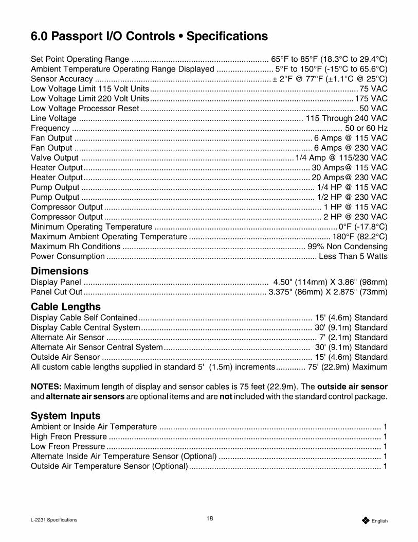
Set Point Operating Range ............................................................ 65°F to 85°F (18.3°C to 29.4°C)Ambient Temperature Operating Range Displayed ......................... 5°F to 150°F (-15°C to 65.6°C)Sensor Accuracy ............................................................................. ± 2°F @ 77°F (±1.1°C @ 25°C)Low Voltage Limit 115 Volt Units........................................................................................... 75 VACLow Voltage Limit 220 Volt Units......................................................................................... 175 VACLow Voltage Processor Reset ............................................................................................... 50 VACLine Voltage .................................................................................................. 115 Through 240 VACFrequency ...................................................................................................................... 50 or 60 HzFan Output ........................................................................................................ 6 Amps @ 115 VACFan Output ........................................................................................................ 6 Amps @ 230 VACValve Output ............................................................................................. 1/4 Amp @ 115/230 VACHeater Output ................................................................................................... 30 Amps@ 115 VACHeater Output ................................................................................................... 20 Amps@ 230 VACPump Output ...................................................................................................... 1/4 HP @ 115 VACPump Output ...................................................................................................... 1/2 HP @ 230 VACCompressor Output ............................................................................................... 1 HP @ 115 VACCompressor Output ............................................................................................... 2 HP @ 230 VACMinimum Operating Temperature ................................................................................ 0°F (-17.8°C)Maximum Ambient Operating Temperature .............................................................. 180°F (82.2°C)Maximum Rh Conditions ................................................................................ 99% Non CondensingPower Consumption ............................................................................................ Less Than 5 Watts
DimensionsDisplay Panel ................................................................................. 4.50" (114mm) X 3.86" (98mm)Panel Cut Out ................................................................................ 3.375" (86mm) X 2.875" (73mm)
Cable LengthsDisplay Cable Self Contained............................................................................ 15' (4.6m) StandardDisplay Cable Central System........................................................................... 30' (9.1m) StandardAlternate Air Sensor ............................................................................................ 7' (2.1m) StandardAlternate Air Sensor Central System................................................................ 30' (9.1m) StandardOutside Air Sensor ............................................................................................ 15' (4.6m) StandardAll custom cable lengths supplied in standard 5' (1.5m) increments............. 75' (22.9m) Maximum
NOTES: Maximum length of display and sensor cables is 75 feet (22.9m). The outside air sensorand alternate air sensors are optional items and are not included with the standard control package.
System InputsAmbient or Inside Air Temperature ................................................................................................. 1High Freon Pressure ....................................................................................................................... 1Low Freon Pressure ........................................................................................................................ 1Alternate Inside Air Temperature Sensor (Optional) ....................................................................... 1Outside Air Temperature Sensor (Optional) .................................................................................... 1
6.0 Passport I/O Controls • Specifications
19 EnglishL-2231 Specifications
Automated Factory Self TestProgramThe Passport I/O software contains a self test programto facilitate factory testing of the entire air conditioningsystem. Once the self test program is activated, the testcycle will continue until the AC power is interrupted orthe Power Button is pressed once which returns thesystem to the Off Mode.
Activate the self test program by pressing the PowerButton while turning on the AC power. Release thePower Button while the display indicates “888” and allLEDs are lit. Passport I/O is now in the self test program.
“tSt” appears in the display while in the self test program.
Once activated the self test software will continuouslyexecute the following procedure:
1. Turn on in the Heat Mode and supply heating for tenminutes.
2. Stop heating and run the fan only for five minutes.
3. Switch to Cool Mode and continue cooling for tenminutes.
4. Stop cooling and run the fan only for five minutes.
5. Return to step one and continue until interrupted.
The self test program will continue until the power isinterrupted or the test is halted by pressing the PowerButton once.
Service ToolsHour MeterTotal compressor cycle time is saved in EEPROM everysix minutes of continuous compressor running time.Cycles less than six minutes are discarded to conservememory and allow the most flexible hour-meter possible.
To view the hour meter turn off the AC power and pressthe Down Button. While holding the Down Button, restoreAC power. After Power-On Reset is complete, thefollowing appears in the display:
1. “Hr” is displayed for one second.
2. The display blanks out for one second then displaysthe thousands of hours for three seconds.
3. The display blanks out for one second then displaysthe hundreds units for three seconds.
4. The unit returns to the last operating state beforepower was removed.
Maximum recorded time is 65,536 hours, the meter stopsand can only be reset by a service technician.
Service History LogPassport I/O records and remembers the eight mostrecent faults. Each time a fault is detected, a one hourtimer is started. Three consecutive faults within that hourcause system shut down, lock out and display the faultcode. During that hour, to conserve memory, the samerecurring fault is not recorded in the service history log.Continuous operation for one hour without the samerecurring fault clears that fault counter but the eventremains in the service history log until over written.Should a different fault be detected during the hour, itwill be entered into the service history log.
The following events are entered into the service historylog:
• High Freon Pressure
• Low Freon Pressure
• Air Sensor Fault
To view the service history log turn off the AC power andpress the Fan Button. With the Fan Button pressed turnon the AC power. Once Power On Reset is completed(display indicates “888” and all LEDs are lit) release theFan Button.
The display will flash the most recent fault detected,followed by the event chronology number. To view otherevents detected press either the Up or Down Buttons.
The service history log can be cleared by simultaneouslypressing the Power and Down buttons.
Exit the service history log by pressing either the Poweror Select Buttons or wait thirty seconds without pressingany button.
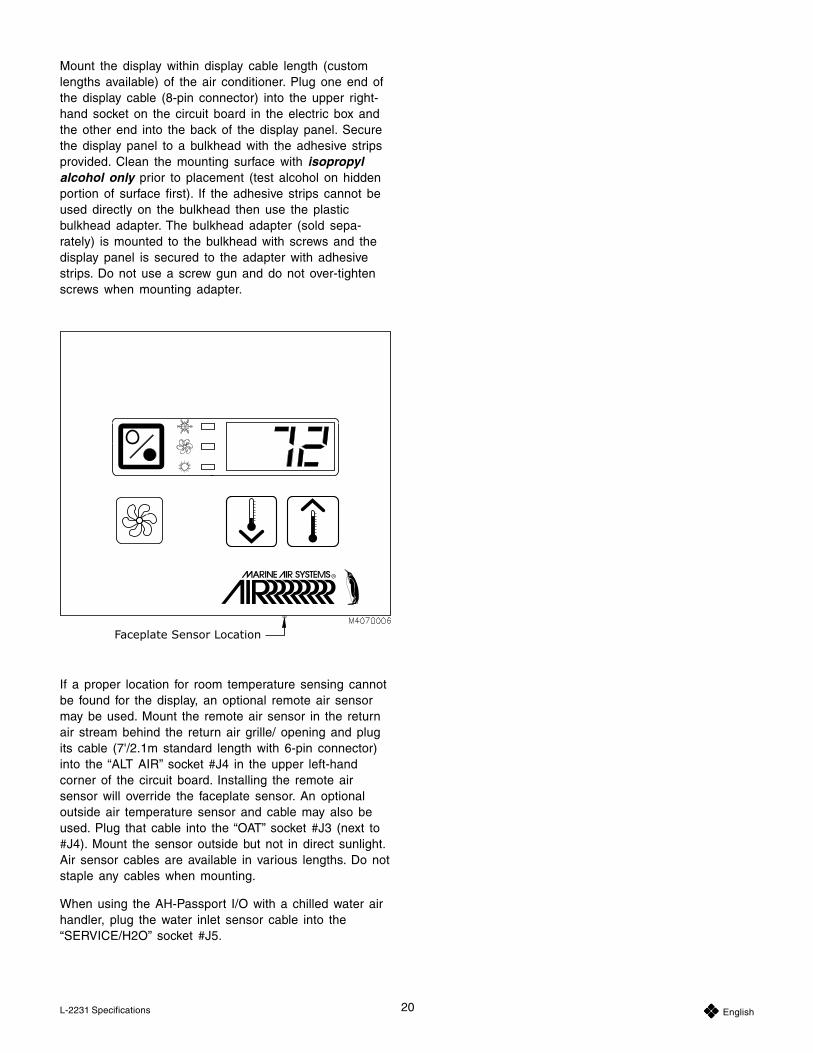
Display Panel InstallationBefore mounting the Passport I/O or AH-Passport I/Odigital display panel touch pad, consider the location.The air sensor built into the display panel will provideexcellent room air temperature sensing given a properinstallation. The display panel should be mounted on aninside wall, slightly higher than mid-height of the cabin,in a location with freely circulating air where it can bestsense average temperature. The cut out size for thedisplay panel is 3.375" (86mm) wide by 2.875" (73mm)high. Do not mount the display in direct sunlight, nearany heat producing appliances or in a bulkhead wheretemperatures radiating from behind the panel may affectperformance. Do not mount the display in the supplyair stream. Do not mount the display above or below asupply or return air grille. Do not mount the displaybehind a door, in a corner, under a stairwell or any placewhere there is no freely circulating air.
20 EnglishL-2231 Specifications
Mount the display within display cable length (customlengths available) of the air conditioner. Plug one end ofthe display cable (8-pin connector) into the upper right-hand socket on the circuit board in the electric box andthe other end into the back of the display panel. Securethe display panel to a bulkhead with the adhesive stripsprovided. Clean the mounting surface with isopropylalcohol only prior to placement (test alcohol on hiddenportion of surface first). If the adhesive strips cannot beused directly on the bulkhead then use the plasticbulkhead adapter. The bulkhead adapter (sold sepa-rately) is mounted to the bulkhead with screws and thedisplay panel is secured to the adapter with adhesivestrips. Do not use a screw gun and do not over-tightenscrews when mounting adapter.
If a proper location for room temperature sensing cannotbe found for the display, an optional remote air sensormay be used. Mount the remote air sensor in the returnair stream behind the return air grille/ opening and plugits cable (7'/2.1m standard length with 6-pin connector)into the “ALT AIR” socket #J4 in the upper left-handcorner of the circuit board. Installing the remote airsensor will override the faceplate sensor. An optionaloutside air temperature sensor and cable may also beused. Plug that cable into the “OAT” socket #J3 (next to#J4). Mount the sensor outside but not in direct sunlight.Air sensor cables are available in various lengths. Do notstaple any cables when mounting.
When using the AH-Passport I/O with a chilled water airhandler, plug the water inlet sensor cable into the“SERVICE/H2O” socket #J5.
21 EnglishL-2231
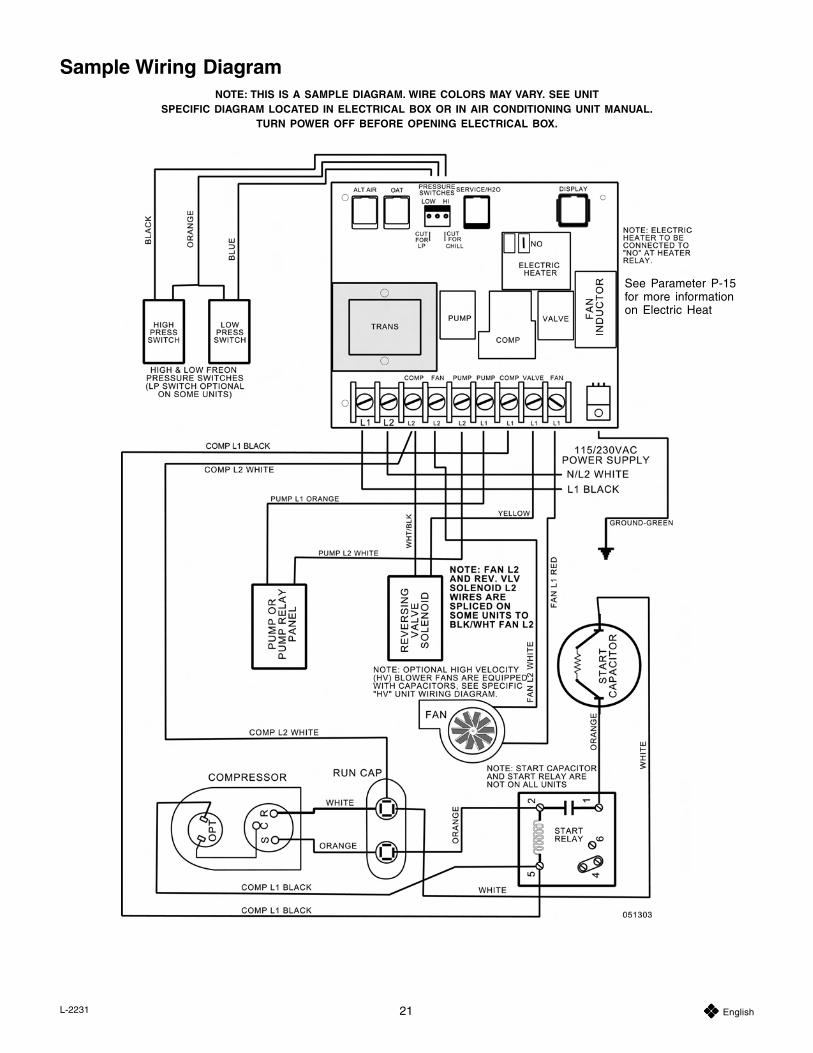
Sample Wiring DiagramNOTE: THIS IS A SAMPLE DIAGRAM. WIRE COLORS MAY VARY. SEE UNIT
SPECIFIC DIAGRAM LOCATED IN ELECTRICAL BOX OR IN AIR CONDITIONING UNIT MANUAL.TURN POWER OFF BEFORE OPENING ELECTRICAL BOX.
See Parameter P-15for more informationon Electric Heat
Marine Air Worldwide Service Dealer LocatorThe majority of the service listings displayed for the United States are key members of the national Marine Air distributor network. If you need service, please contact the closest company shown. In most cases they will direct you to a local dealer or service port. We have over 500 Marine Air dealers in the national Marine Air network, and one should be convenient to you.
The international companies listed are, in many cases, distributors and are capable of managing the majority of service requests
for the countries listed. In some cases they will refer you to a local dealer.
You may also contact us directly via the web site or call us in the US at (954) 973-2477.
For a complete and up-to-date Dealer locator list, please visit our website at http://www.marineair.com/locator/index.html
USAAlabama
AER Marine Supply
(281) 474-3276(281) [email protected]
Phone:Fax:
Location: Seabrook, TX, USA
E-mail:
Alaska
American Marine Contractors
(206) 660-2240(206) [email protected]
Phone:Fax:
Location: Seattle, WA, USA
E-mail:
Arizona
Southern California Marine Enterprises
619-224-2869619-226-0496sales@southerncalmarine.comwww.southerncalmarine.com
Phone:Fax:
Location: San Diego, CA, USA
E-mail:Web:
Arkansas
AER Marine Supply
(281) 474-3276(281) [email protected]
Phone:Fax:
Location: Seabrook, TX, USA
E-mail:
California
Southern California Marine Enterprises
619-224-2869619-226-0496sales@southerncalmarine.comwww.southerncalmarine.com
Phone:Fax:
Location: San Diego, CA, USA
E-mail:Web:
Colorado
AER Marine Supply
(281) 474-3276(281) [email protected]
Phone:Fax:
Location: Seabrook, TX, USA
E-mail:
Connecticut
Ocean Options
(401) 624-7334(401) [email protected]
Phone:Fax:
Location: Tiverton, RI, USA
E-mail:Web:
Delaware
Ocean Options - Mid Atlantic
(410) 268-9365(410) [email protected]
Phone:Fax:
Location: Annapolis, MD, USA
E-mail:Web:
Florida (North)
Beard Marine Savannah - Distributor
(912) 356-5222(912) [email protected]
Phone:Fax:
Location: Savannah, GA, USA
E-mail:Web:
Florida (South)
Territory: Fort Lauderdale
ARW Maritime - Dealer
(954) 463-0110(954) [email protected]
Phone:Fax:
Location: Ft. Lauderdale, Florida, USA
E-mail:
Territory: Fort Lauderdale
Beard Marine - Ft. Lauderdale - Dealer
(954) 463-2288(954) [email protected]
Phone:Fax:
Location: Ft. Lauderdale, Florida, USA
E-mail:Web:
Territory: Riviera Beach
Beard Marine of the Palm Beaches - Dealer
(561) 881-9598(561) [email protected]
Phone:Fax:
Location: Riviera Beach, Florida, USA
E-mail:
Territory: Fort Lauderdale
Cable Marine - Dealer
(954) 462-2840(954) 523-3686www.cablemarine.com
Phone:Fax:
Location: Ft. Lauderdale, Florida, USA
Web:
Territory: Ft. Lauderdale
Comfort Marine - Dealer
(954) 257-9848(954) 689-7332
Phone:Fax:
Location: Ft. Lauderdale, FL, USA
Territory: West Palm Beach
Cowherd Marine - Dealer
(561) 844-1666(561) 844-1628
Phone:Fax:
Location: Lake Park, Florida, USA
Territory: South Florida
Dometic Corporation-Environmental Systems, Distributor
(954) 973-2477(954) [email protected]
Phone:Fax:
Location: Pompano Beach, FL, USA
E-mail:Web:
Territory: Ft. Lauderdale, Miami
Edd Helms Marine Air Conditioning - Dealer
954 522 2520954 522 [email protected]
Phone:Fax:
Location: Miami, Florida, USA
E-mail:
Florida (South)
Territory: Tampa-St Petersburg
IYS Marine - Dealer
(727) 521-6650(727) [email protected]
Phone:Fax:
Location: Pinellas Park, Florida, USA
E-mail:
Territory: Port Charlotte
Jim's Marine A/C - Dealer
(941) 629-8788Phone:
Location: Port Charlotte, Florida, USA
Territory: Port St. Lucie
Marine Air Conditioning - Dealer
(772) 464-7896(772) 464-8697
Phone:Fax:
Location: Ft. Pierce, Florida, USA
Territory: Miami
Masters Marine Center, Inc. - Dealer
(305) 891-1236(305) 891-8700
Phone:Fax:
Location: Miami, Florida, USA
Territory: Fort Lauderdale
Neptune Air Corporation - Dealer
(954) 792-6550(954) 792-6551
Phone:Fax:
Location: Ft. Lauderdale, Florida, USA
Territory: West Palm Beach
Palm Beach Aqua Air - Dealer
(561) 832-8820(561) 659-7918
Phone:Fax:
Location: West Palm Beach, Florida, USA
Territory: Florida Keys
Sea Air Land Technologies - Dealer
(305) 289-1150(305) [email protected]
Phone:Fax:
Location: Marathon, Florida, USA
E-mail:Web:
Territory: Lighthouse Point
Sea Breeze Marine - Dealer
(954) 427-3843(561) 368-0463
Phone:Fax:
Location: Lighthouse Point, Florida, USA
Territory: Fort Myers
Tropica Boats & Marine, Inc. - Dealer
(239) 694-5259(239) [email protected]
Phone:Fax:
Location: Fort Myers, Florida, USA
E-mail:Web:
Territory: Sebastian
Ty Cobb Services, Inc. - Dealer
(772) 388-5966(772) 581-0056
Phone:Fax:
Location: Sebastian, Florida, USA
L-2205M Revised: 9-30-05
Georgia
Beard Marine Savannah - Distributor
(912) 356-5222(912) [email protected]
Phone:Fax:
Location: Savannah, GA, USA
E-mail:Web:
Hawaii
Southern California Marine Enterprises
619-224-2869619-226-0496sales@southerncalmarine.comwww.southerncalmarine.com
Phone:Fax:
Location: San Diego, CA, USA
E-mail:Web:
Idaho
American Marine Contractors
(206) 660-2240(206) [email protected]
Phone:Fax:
Location: Seattle, WA, USA
E-mail:
Illinois
Midwest Marine Supply
(586) 778-8950(586) 778-6108
Phone:Fax:
Location: St. Clair Shores, MI, USA
Indiana
Midwest Marine Supply
(586) 778-8950(586) 778-6108
Phone:Fax:
Location: St. Clair Shores, MI, USA
Iowa
Midwest Marine Supply
(586) 778-8950(586) 778-6108
Phone:Fax:
Location: St. Clair Shores, MI, USA
Kansas
AER Marine Supply
(281) 474-3276(281) [email protected]
Phone:Fax:
Location: Seabrook, TX, USA
E-mail:
Kentucky
Midwest Marine Supply
(586) 778-8950(586) 778-6108
Phone:Fax:
Location: St. Clair Shores, MI, USA
Louisiana
AER Marine Supply
(281) 474-3276(281) [email protected]
Phone:Fax:
Location: Seabrook, TX, USA
E-mail:
Maine
Ocean Options
(401) 624-7334(401) [email protected]
Phone:Fax:
Location: Tiverton, RI, USA
E-mail:Web:
Maryland
Ocean Options - Mid Atlantic
(410) 268-9365(410) [email protected]
Phone:Fax:
Location: Annapolis, MD, USA
E-mail:Web:
Massachusetts
Ocean Options
(401) 624-7334(401) [email protected]
Phone:Fax:
Location: Tiverton, RI, USA
E-mail:Web:
Michigan
Midwest Marine Supply
(586) 778-8950(586) 778-6108
Phone:Fax:
Location: St. Clair Shores, MI, USA
Minnesota
Midwest Marine Supply
(586) 778-8950(586) 778-6108
Phone:Fax:
Location: St. Clair Shores, MI, USA
Mississippi
AER Marine Supply
(281) 474-3276(281) [email protected]
Phone:Fax:
Location: Seabrook, TX, USA
E-mail:
Missouri
AER Marine Supply
(281) 474-3276(281) [email protected]
Phone:Fax:
Location: Seabrook, TX, USA
E-mail:
Montana
American Marine Contractors
(206) 660-2240(206) [email protected]
Phone:Fax:
Location: Seattle, WA, USA
E-mail:
Nevada
AER Marine Supply
(281) 474-3276(281) [email protected]
Phone:Fax:
Location: Seabrook, TX, USA
E-mail:
New Hampshire
Ocean Options
(401) 624-7334(401) [email protected]
Phone:Fax:
Location: Tiverton, RI, USA
E-mail:Web:
New Jersey
Territory: New York, New Jersey
Marine Specialists
(631) 580-0545(631) [email protected]
Phone:Fax:
Location: Ronkonkoma, NY, USA
E-mail:Web:
New Mexico
AER Marine Supply
(281) 474-3276(281) [email protected]
Phone:Fax:
Location: Seabrook, TX, USA
E-mail:
New York
Territory: New York, New Jersey
Marine Specialists
(631) 580-0545(631) [email protected]
Phone:Fax:
Location: Ronkonkoma, NY, USA
E-mail:Web:
North Carolina
Beard Marine Savannah - Distributor
(912) 356-5222(912) [email protected]
Phone:Fax:
Location: Savannah, GA, USA
E-mail:Web:
North Dakota
Midwest Marine Supply
(586) 778-8950(586) 778-6108
Phone:Fax:
Location: St. Clair Shores, MI, USA
Ohio
Midwest Marine Supply
(586) 778-8950(586) 778-6108
Phone:Fax:
Location: St. Clair Shores, MI, USA
Oklahoma
AER Marine Supply
(281) 474-3276(281) [email protected]
Phone:Fax:
Location: Seabrook, TX, USA
E-mail:
Oregon
American Marine Contractors
(206) 660-2240(206) [email protected]
Phone:Fax:
Location: Seattle, WA, USA
E-mail:
Pennsylvania
Ocean Options - Mid Atlantic
(410) 268-9365(410) [email protected]
Phone:Fax:
Location: Annapolis, MD, USA
E-mail:Web:
Rhode Island
Ocean Options
(401) 624-7334(401) [email protected]
Phone:Fax:
Location: Tiverton, RI, USA
E-mail:Web:
South Carolina
Beard Marine Savannah - Distributor
(912) 356-5222(912) [email protected]
Phone:Fax:
Location: Savannah, GA, USA
E-mail:Web:
South Dakota
Midwest Marine Supply
(586) 778-8950(586) 778-6108
Phone:Fax:
Location: St. Clair Shores, MI, USA
Tennessee
Beard Marine Savannah - Distributor
(912) 356-5222(912) [email protected]
Phone:Fax:
Location: Savannah, GA, USA
E-mail:Web:
Texas
AER Marine Supply
(281) 474-3276(281) [email protected]
Phone:Fax:
Location: Seabrook, TX, USA
E-mail:
L-2205M Revised: 9-30-05
Utah
AER Marine Supply
(281) 474-3276(281) [email protected]
Phone:Fax:
Location: Seabrook, TX, USA
E-mail:
Vermont
Ocean Options
(401) 624-7334(401) [email protected]
Phone:Fax:
Location: Tiverton, RI, USA
E-mail:Web:
Virginia
Ocean Options - Mid Atlantic
(410) 268-9365(410) [email protected]
Phone:Fax:
Location: Annapolis, MD, USA
E-mail:Web:
Washington
American Marine Contractors
(206) 660-2240(206) [email protected]
Phone:Fax:
Location: Seattle, WA, USA
E-mail:
West Virginia
Ocean Options - Mid Atlantic
(410) 268-9365(410) [email protected]
Phone:Fax:
Location: Annapolis, MD, USA
E-mail:Web:
Wisconsin
Midwest Marine Supply
(586) 778-8950(586) 778-6108
Phone:Fax:
Location: St. Clair Shores, MI, USA
Wyoming
American Marine Contractors
(206) 660-2240(206) [email protected]
Phone:Fax:
Location: Seattle, WA, USA
E-mail:
Antigua
Aboard Refrigeration
(268) 460-1690(419) [email protected]
Phone:Fax:
Location: , Antigua, West Indies
E-mail:Web:
Argentina
Baron SRL
(54) 11-4-580-5556(54) [email protected]
Phone:Fax:
Location: San Fernando, Buenos Aires, Argentina
E-mail:Web:
Australia
Seairland Systems, Inc.
(61) 7-3268-7511(61) [email protected]
Phone:Fax:
Location: Brisbane, Queensland, Australia
E-mail:
Austria
Dometic Marine – Italy, Sales Company
390 26172583390 [email protected]
Phone:Fax:
Location: Milano, Italy
E-mail:Web:
Bahamas
Territory: Nassau
Freezing Point, Ltd.
(242) 325-3589(242) [email protected]
Phone:Fax:
Location: Nassau, Bahamas
E-mail:
Bahrain
International Agencies Co.
973-17728691973-17728412
Phone:Fax:
Location: Manama, Bahrain
Mantech
(971) 4-3332-542(971) 4-3330-649
Phone:Fax:
Location: Dubai, United Arab Emirates
Brazil
Marine Express
55-11-5182-716655-11-5183-3636fabrizio@marinexpress.com.brwww.marinexpress.com.br
Phone:Fax:
Location: Sao Paulo, Brazil
E-mail:Web:
British Virgin Islands
BVI Marine Management
(284) 494-2938(284) 494-5006
Phone:Fax:
Location: Roadtown, Tortola, British Virgin Islands
C & G Refrigeration
(284) 776-0038Phone:
Location: , Tortola, British Virgin Islands
CanadaBritish Columbia
American Marine Contractors
(206) 660-2240(206) [email protected]
Phone:Fax:
Location: Seattle, WA, USA
E-mail:
Ontario
Territory: Queensville
Northland Supply Company
(905) 478-2244(905) [email protected]
Phone:Fax:
Location: Queensville, Ontario, Canada
E-mail:Web:
Territory: All Canadian Provinces except BC
Woodard and Company - Manufacturer's Rep.
(905)760-0245(905)[email protected]
Phone:Fax:
Location: Concord, Ontario, Canada
E-mail:
Quebec
Territory: Drummondville, Quebec
Kimpex, Inc.
(705) 721-0947(705) [email protected]://www.kpx-kimpex.com
Phone:Fax:
Location: Drummondville, Quebec, Canada
E-mail:Web:
Caribbean Islands
Aboard Refrigeration
(268) 460-1690(419) [email protected]
Phone:Fax:
Location: , Antigua, West Indies
E-mail:Web:
BVI Marine Management
(284) 494-2938(284) 494-5006
Phone:Fax:
Location: Roadtown, Tortola, British Virgin Islands
C & G Refrigeration
(284) 776-0038Phone:
Location: , Tortola, British Virgin Islands
Centro Cruisair de Puerto Rico
Phone:Fax:
Location: San Turce, Puerto Rico
E-mail:
Cool-Tech Air Condition
(787) 860-2615(787) [email protected]/cooltech
Phone:Fax:
Location: Fajardo, Puerto Rico
E-mail:Web:
Enertech N.V.
599-551-2145305-675-5857 (USA)[email protected]
Phone:Fax:
Location: Simpson Bay, St. Maarten/St. Martin, Netherland Antilles
E-mail:
Territory: Nassau
Freezing Point, Ltd.
(242) 325-3589(242) [email protected]
Phone:Fax:
Location: Nassau, Bahamas
E-mail:
May Day Marine
787-751-0490787-790-2551
Phone:Fax:
Location: San Juan, Puerto Rico
Nau-T-Kol Marine Refrigeration
Phone:Fax:
Location: Chaguaramas, Trinidad
E-mail:Web:
Reefco, Inc.
(340) 776-0038(340) [email protected]
Phone:Fax:
Location: , St. Thomas, US Virgin Islands
E-mail:Web:
Regis Electronics (St Lucia) LTD.
Phone:Fax:
Location: St. Lucia, West Indies
E-mail:
Territory: Carolin
Sun Cool Air Conditioning
(787) 791-6971(787) [email protected]
Phone:Fax:
Location: Carolina, Puerto Rico, Puerto Rico
E-mail:
China
Flash Marine Trading Pte.Ltd.
(86 21) 509 04120(86 21) 509 [email protected]
Phone:Fax:
Location: Shanghai, China
E-mail:
L-2205M Revised: 9-30-05
Costa Rica
Territory: Costa Rica, Panama
Gato Frío
Phone:Fax:
Location: Playa Jaco, Costa Rica
E-mail:
Croatia
Dometic Marine – Italy, Sales Company
390 26172583390 [email protected]
Phone:Fax:
Location: Milano, Italy
E-mail:Web:
Cyprus
Dometic Marine - United Kingdom, Sales Company
44 (0) 870 330610144 (0) 870 [email protected]
Phone:Fax:
Location: Poole, Dorset, England
E-mail:Web:
Dominican Republic
May Day Marine
787-751-0490787-790-2551
Phone:Fax:
Location: San Juan, Puerto Rico
Ecuador
Quasar Nautica, S.A.
(593) 2-446-996/997(593) 2-436-625
Phone:Fax:
Location: P.O. Box 17-01-0069, Quito, Ecuador
Egypt
Engineering Air
202 4829341202 4829341
Phone:Fax:
Location: Abasia, Cairo, Eygpt
France
Dometic Marine – France, Sales Company
Cell: 0033 (0)680 415 5430033 (0)344 633 [email protected]
Phone:Fax:
Location: Plailly, France
E-mail:Web:
PolyMarine Distribution (C/O Occas Marine)
0033 4934636340033 [email protected]
Phone:Fax:
Location: Le Cannet, Rocheville, France
E-mail:
Greece
Dometic Marine - United Kingdom, Sales Company
44 (0) 870 330610144 (0) 870 [email protected]
Phone:Fax:
Location: Poole, Dorset, England
E-mail:Web:
Athens
Territory: Athens
Aegean Diesel Electric Ltd.
Phone:Fax:
Location: Athens, Piraeus, Greece
E-mail:
Hong Kong
Piercey Marine Limited
(852) 2791-4106(852) [email protected]
Phone:Fax:
Location: Sai Kung, NT, Hong Kong
E-mail:
Italy
Condaria 87 SRL
39 0362 4418239 0362 452226
Phone:Fax:
Location: Nova Milanese (MI), Italy
Dometic Marine – Italy, Sales Company
390 26172583390 [email protected]
Phone:Fax:
Location: Milano, Italy
E-mail:Web:
Japan
Tominaga & Company, Ltd.
Phone:Fax:
Location: Osaka, Japan
E-mail:
Kuwait
Mantech
(971) 4-3332-542(971) 4-3330-649
Phone:Fax:
Location: Dubai, United Arab Emirates
Sammari Marine Trading
965-5740408965-5715655
Phone:Fax:
Location: Al-Shawikh, Kuwait
Malta
Dometic Marine - United Kingdom, Sales Company
44 (0) 870 330610144 (0) 870 [email protected]
Phone:Fax:
Location: Poole, Dorset, England
E-mail:Web:
Inmartech Ltd.
00356 2137647600356 21376476
Phone:Fax:
Location: Swieqi, STJ 04, Malta
Mexico
Southern California Marine Enterprises
619-224-2869619-226-0496sales@southerncalmarine.comwww.southerncalmarine.com
Phone:Fax:
Location: San Diego, CA, USA
E-mail:Web:
Netherlands
Eberca
31 1866 2195531 1866 [email protected]
Phone:Fax:
Location: , Netherlands
E-mail:
Heinen & Hopman Eng. Bv.
(31) (0) 33 2992500(31) (0) 33 299 [email protected]
Phone:Fax:
Location: Spakenburg, Netherlands
E-mail:Web:
Netherlands Antilles
Enertech N.V.
599-551-2145305-675-5857 (USA)[email protected]
Phone:Fax:
Location: Simpson Bay, St. Maarten/St. Martin, Netherland Antilles
E-mail:
New Zealand
Whiting Power Systems
Phone:Fax:
Location: 192 Herne Bay, Auckland, New Zealand
E-mail:Web:
Oman
Mantech
(971) 4-3332-542(971) 4-3330-649
Phone:Fax:
Location: Dubai, United Arab Emirates
OHI Marine LLC
968-712240968-712085
Phone:Fax:
Location: Muscat, Oman
Panama
Territory: Costa Rica, Panama
Gato Frío
Phone:Fax:
Location: Playa Jaco, Costa Rica
E-mail:
Territory: Panama
Productos Marine Air
Phone:Fax:
Location: La Chorrea, Panama
E-mail:
Portugal
Territory: Portugal
PowerCool Lda
351 91 786 63 73351 282 461 [email protected]
Phone:Fax:
Location: Portimao, Portugal
E-mail:Web:
Puerto Rico
Centro Cruisair de Puerto Rico
Phone:Fax:
Location: San Turce, Puerto Rico
E-mail:
Cool-Tech Air Condition
(787) 860-2615(787) [email protected]/cooltech
Phone:Fax:
Location: Fajardo, Puerto Rico
E-mail:Web:
May Day Marine
787-751-0490787-790-2551
Phone:Fax:
Location: San Juan, Puerto Rico
Territory: Carolin
Sun Cool Air Conditioning
(787) 791-6971(787) [email protected]
Phone:Fax:
Location: Carolina, Puerto Rico, Puerto Rico
E-mail:
L-2205M Revised: 9-30-05

Qatar
Al-Badi Trading Co.
974-4320715974-4442888
Phone:Fax:
Location: Doha, Qatar
Mantech
(971) 4-3332-542(971) 4-3330-649
Phone:Fax:
Location: Dubai, United Arab Emirates
Russia
Standarte
7 095 575 67 237 095 575 39 [email protected]
Phone:Fax:
Location: Starbeevo, Moscow region, Russia
E-mail:Web:
Saudi Arabia
Mantech
(971) 4-3332-542(971) 4-3330-649
Phone:Fax:
Location: Dubai, United Arab Emirates
Territory: Saudi Arabia
Samaco Marine Division
(966) 2-699-2300(966) 2-699-1024
Phone:Fax:
Location: Alnahdah dis Jeddah, Saudi Arabia
Scandinavia
Dometic Marine – Nordic Sales, Sales Company
46 3516570046 [email protected]
Phone:Fax:
Location: Halmstad, Sweden
E-mail:Web:
Singapore
Territory: Singapore
Tritex Equipment PTE, Ltd.
(65) 6861-1188(65) [email protected]
Phone:Fax:
Location: , Singapore
E-mail:
Slovenia
Dometic Marine – Italy, Sales Company
390 26172583390 [email protected]
Phone:Fax:
Location: Milano, Italy
E-mail:Web:
South Africa
C-Dynamics cc
27 21 555 323227 21 555 [email protected]
Phone:Fax:
Location: Cape Town, South Africa
E-mail:Web:
Spain
Acastimar
Phone:Fax:
Location: Tarragona, Spain
E-mail:
Dometic Marine – France, Sales Company
Cell: 0033 (0)680 415 5430033 (0)344 633 [email protected]
Phone:Fax:
Location: Plailly, France
E-mail:Web:
Techno Electronica Naval, S.A.
34 (93) 664-49-7034 (93) [email protected]
Phone:Fax:
Location: Barcelona, Spain
E-mail:Web:
Sri Lanka
G&M Enterprises
94 11 269196694 11 [email protected]
Phone:Fax:
Location: Borella-Colombo 8, Sri Lanka
E-mail:
Sweden
Dometic Marine – Nordic Sales, Sales Company
46 3516570046 [email protected]
Phone:Fax:
Location: Halmstad, Sweden
E-mail:Web:
Thailand
Thai Kolon Co. Ltd.
66-2-745-6468-77 (10 lines)[email protected]
Phone:Fax:
Location: Bangkok, Thailand
E-mail:
Trinidad & Tobago
Nau-T-Kol Marine Refrigeration
Phone:Fax:
Location: Chaguaramas, Trinidad
E-mail:Web:
Turkey
Dometic Marine - United Kingdom, Sales Company
44 (0) 870 330610144 (0) 870 [email protected]
Phone:Fax:
Location: Poole, Dorset, England
E-mail:Web:
Egemar Muhendiscik Ltd.
90 216 494 216890 216 494 [email protected]
Phone:Fax:
Location: Tuzla, Istanbul, Turkey
E-mail:Web:
U.S. Virgin Islands
Reefco, Inc.
(340) 776-0038(340) [email protected]
Phone:Fax:
Location: , St. Thomas, US Virgin Islands
E-mail:Web:
Ukraine
Standarte
7 095 575 67 237 095 575 39 [email protected]
Phone:Fax:
Location: Starbeevo, Moscow region, Russia
E-mail:Web:
United Arab Emirates
Mantech
(971) 4-3332-542(971) 4-3330-649
Phone:Fax:
Location: Dubai, United Arab Emirates
United Kingdom
Dometic Marine - United Kingdom, Sales Company
44 (0) 870 330610144 (0) 870 [email protected]
Phone:Fax:
Location: Poole, Dorset, England
E-mail:Web:
Uruguay
Baron SRL
(54) 11-4-580-5556(54) [email protected]
Phone:Fax:
Location: San Fernando, Buenos Aires, Argentina
E-mail:Web:
Venezuela
Rich Marine Center
(58) 281 2181630(58) [email protected]
Phone:Fax:
Location: Complejo Turistico El Morro, Venezuela, South America
E-mail:Web:
West Indies
Aboard Refrigeration
(268) 460-1690(419) [email protected]
Phone:Fax:
Location: , Antigua, West Indies
E-mail:Web:
Regis Electronics (St Lucia) LTD.
Phone:Fax:
Location: St. Lucia, West Indies
E-mail:
Yemen
Mantech
(971) 4-3332-542(971) 4-3330-649
Phone:Fax:
Location: Dubai, United Arab Emirates
L-2205M Revised: 9-30-05


L-2231
Dometic Environmental Corporation2000 N. Andrews Ave. Ext. • Pompano Beach, FL 33069-1497 USAPhone: 954-973-2477 • Facsimile: 954-979-4414 • Service Fax: 954-973-8795
For Sales and Service Calls within Europe and the Middle East, please contact +44 (0) 870 330 6101
Website: www.marineair.com • Email: [email protected]