kunwoo structural eng. -...
TRANSCRIPT
PRO.IECT NO.
- -
STRUCTURAL DESIGN AND ANALYSIS
v-7 % :J KUNWOO STRUCTURAL ENG.
Al&AI 7Z? 925 197-5 ~b 4 IT 14 8022
TEL : 02-2028-180314 FAX : 02-2028-1802

STRUCTURAL DESIGN AND ANALYSIS
41 Z 5 G 3 $@R&II~~+@ (DESIGNED BY) (CHECKED BY) (APPROVED by)
KOREAN PROFESSIONAL I $ @ *
ENGINEERS OI XH E O F o I & % j 3 @ ? + 0 2
ASSOCIATION 1

M 0 1 A IV . 3ZOH 7 $11 DATA ................................................................................................................. 77
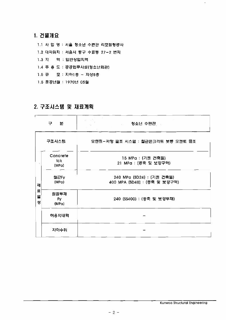
Concrete fck
(MPa)
15 MPa : (31E 34=) 21 MPa : (735 Z ZS7q)
240 MPa (SD24) : PIE Z7S) 400 MPA (SD40) : (85 9 g37q)
Kunwoo Structural Engineering
- 2 -
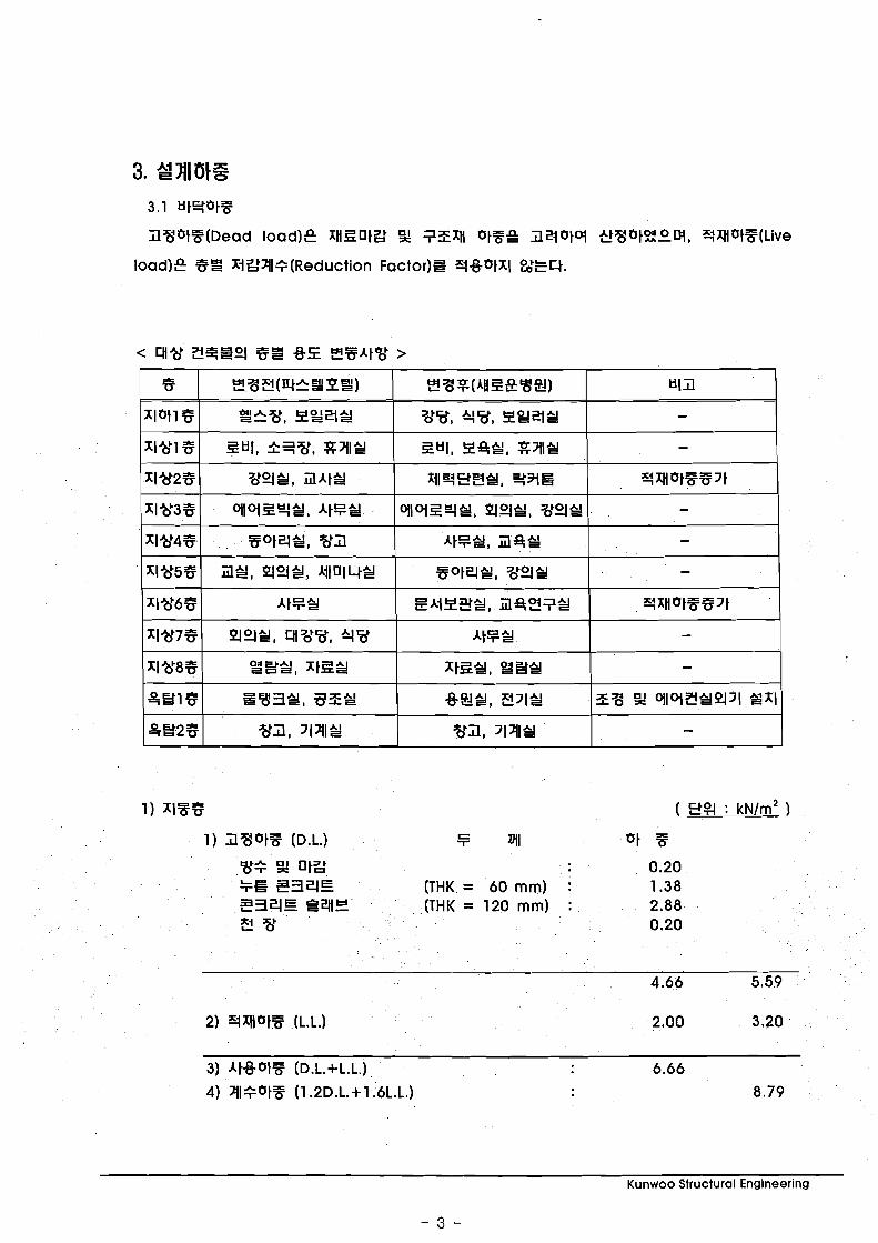
(THK = 60 mm) : 234E S4lE (THK = 120 mm) : 2.88 3 w 0.20
Kunwoo Structural Engineering
- 3 -
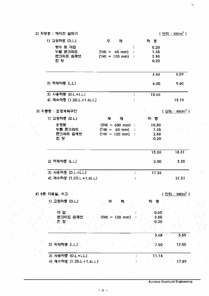
%+ 52 O f 2 0.20 k% Z34E (THK = 60 mm) : 1.38 Z34E E3qY (THK = 120 mm) : 2.88 2 '6' 0.20
2) X-lxHatT (L.L.) 6.00 9.60
33E (THK = 600 mm) : 10.80 =a Z34E (THK = 60 mm) : 1.38 Z34E $41: (THK = 120 mm) : 2.88 2 '6' 0.20
01 2 0.60 Z34E QiAE (THK = 120 mm) : 2.88 2 'b' 0.20
Kunwoo Structural Engineering
- 4 -

0 lLk 0.40 S34E P41E (THK = 120 mm) : 2.88 2 8 0.20
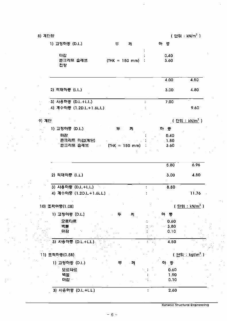
2) YxHotF (L.L.) 3.00 4.80
1) JVotF (D.L.) F 7111 01 5
0 ISk 0.40 S34E P41E (THK = 120 mm) : 2.88 3 0.20
1) JVotF (D.L.) F 7111 01 7? of&F 0.40 F2 S34E (THK = 200 mm) : 4.60 S34E S2H: (THK = 120 mm) : 2.88 E!w 0.20
Kunwoo Structural Engineering
- 5 -
8) 211SRC: ( S % : k ~ l m ~ )
1) Z V b t F (D.L.) 5 nll Of ??
1 tgk 0.40 Z34E P W (THK = 150 mm) : 3.60 3%
1) Z V b t F (D.L.1 5 nll 01 F 1 I&' 0.40 E34E OtZ(211S) 1.80 Z34E P W (THK = 150 mm) : 3.60
I) ilgbtz (D.L.1 F nll bt F
1) i l V 0 t Z (D.L.1 F nll bt %
Kunwoo Structural Engineering
- 6 -
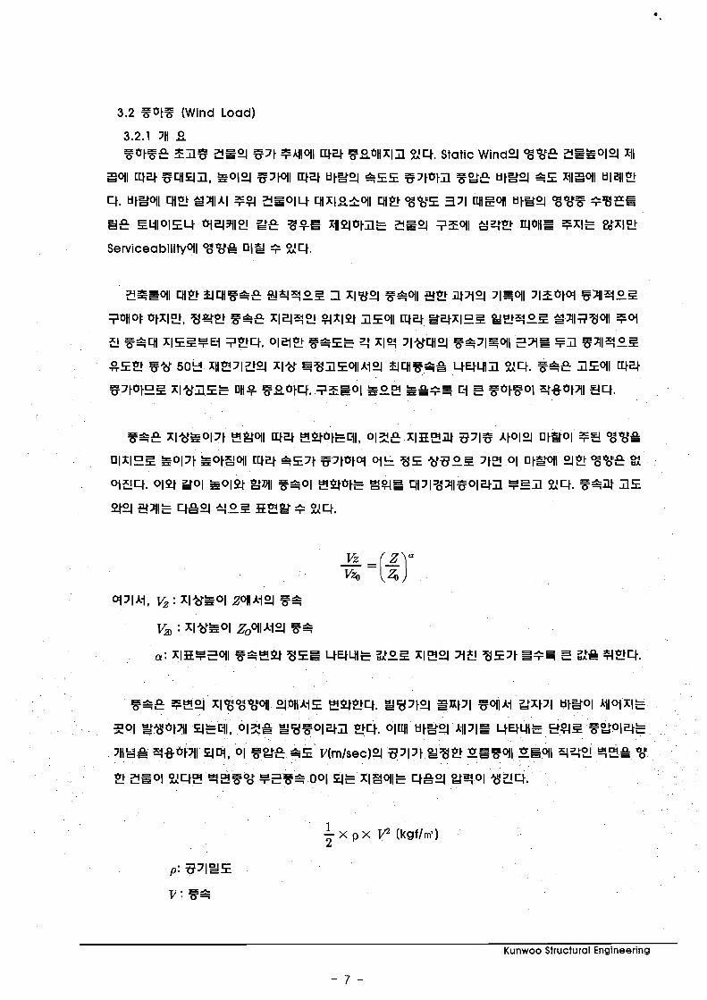
3.2 %btF (Wind Load)
3.2.1 7H 8 8btFE Z l $ ZE9 -171 5Yloll W 4 F 8 b H x I l 24. Static Wind9 % % E 2Eh019 111
Boll c44 5 4 1 4 3 , S o l 9 -17tol1 W 4 H I S 9 SEE - 1 7 t b t l FgE H I S 9 SE xiIBol1 Hli!Il?2
4. HtSoll US SAlA1 ?$I 2E014 Ux18zkoll 4% % % E 371 WIBOII H I S 9 % % F +VEZ
Kunwoo Structural Engineering
- 7 -

Kunwoo Structural Engineering
- 8 -
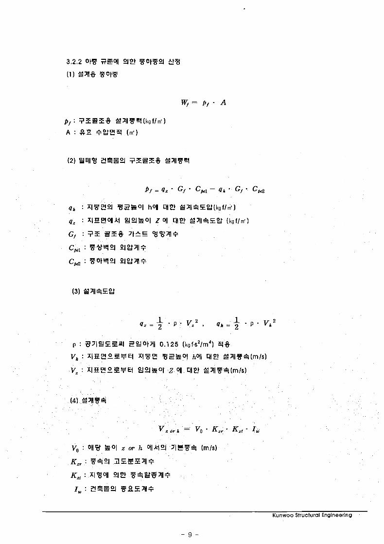
q h : x I E Z 9 B Z h o I hql 4 1 2 3 A 1 9 E g ( k g f / m 1 ]
q, : xIEZOllA1 g90-lh01 Z oll 4 1 2 S A 1 4 E g (kgf/mt)
Gf : 7 E SZ% 7tAE OG%AI+
C,, : F3q9 PIE2118
K,, : 549 i l E E ! E A l +
K,, : ~l8 '01l 9 2 F462 '341+
I , : E7=9 5 8 E A 1 8
Kunwoo Structural Engineering
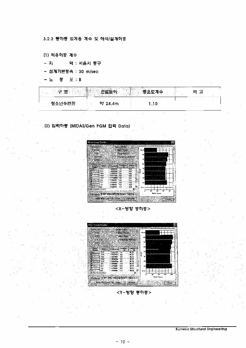
(1) q 9 6 t F 2(1+
- XI : Al-181.1 87
- S2(lJIET+ : 30 mlsec
- 5 E : B
(2) Od$bt8 (MIDASlGen PGM Od9 Data)
Kunwoo Structural Engineering
3.3 XIYOtF (Earthquake Load)
Kunwoo Structural Engineering
X I Z ~ t B O I I qS ES2!39, i 5 x l E ! d t Z , 52!39, + % H I E 3 PYE, ZE PEE 5011 xi
bo'g 2' ZEZ 2 2 1 l b t q O l b t W , 71q E2599 S X d Y S ? t 34*Y4 ef i l Z l b t q X lE !b tZ
oll E t 2 b t E E b t % U .
Kunwoo Structural Engineering
- 12 -
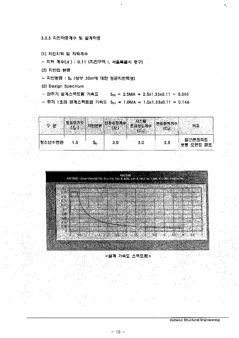
( 1 ) xIz!xlq 3 x1q211e
- x l q Al+(A) : 0.1 1 (xI?i!7? I, A i & F = A l Z 7 )
(2) 1159 ZE
- x l S 3 E : Sb (%F 30moll 419 %SxlSG"cj)
(3) Design Spectrum
Kunwoo Structural Engineering
- 13 -
5) L H Z S A I Xl*dAl q 3 O l l 32 27 (1987, ql237!%PI)
6) 3gE a t g 2 l e "x' (2000, q 2 3 g q Q )
7) ACI 318-99 CODE
4.2 E!l%P!
1) 7 3 A l 3 , q l q Z G W I , 2 I % V
2) Zl?5 Z!=9 73413 "x' 241, E!8+ Q, 2!73273?3!%PI
3) Steel, Concrete, and Composite Design of Tall Buildings, Bungle S. Taranath,
McGraw-Hill.
5. A t 8 EZ1Z 5.1 S3OH4 "x' P A 1 8 EZIlEJ
1) MIDASIGen Ver. 7.4.1 (General design system)
2) MIDASISDS Ver. 3.4.0 (Slab & basement Design System for windows)
1) MlDASlSet Ver. 3.3.4 (Structural engineer's tools)
Kunwoo Structural Engineering
- 14 -

Kunwoo Structural Engineering
- 15 -

Kunwoo Structural Engineering
- 16 -

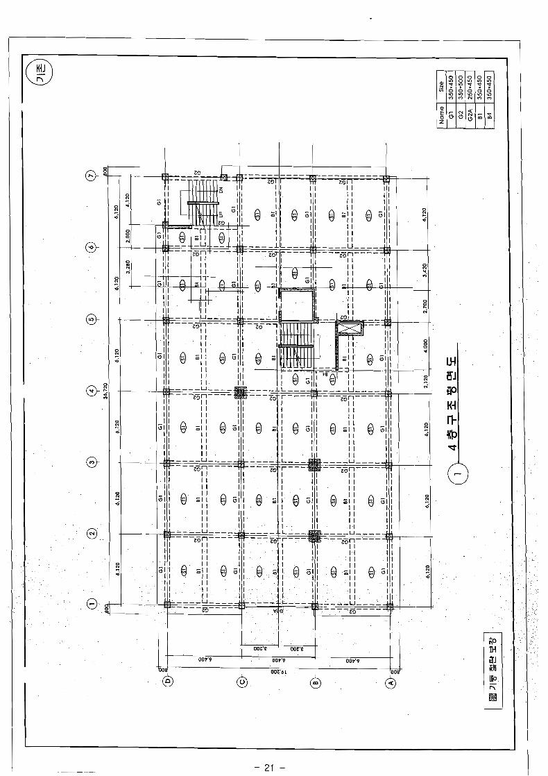

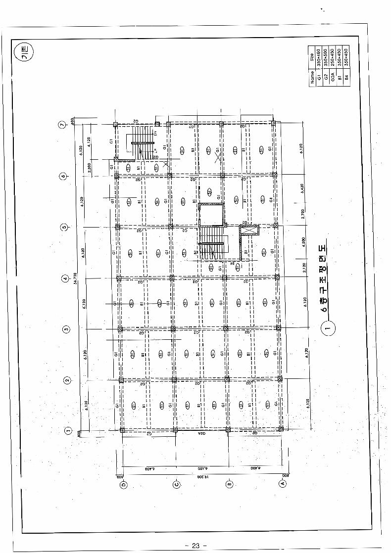

OOZ'E OOZ'C I


--zin----
I I I
OOV'9 OOV'P OOV.9
OOZ'bL
6 6 6 6"

Kunwoo Structural Engineering
- 28 -


Kunwoo Structural Engineering
- 39 -

Kunwoo Structural Engineering
- 40 -


1 I 1 1 1 090'9 OPP'L OOP'9 000'C OOP'E OOP'9
1 NIJ 1 is j / - i 6 1 in ' I - I I an1 I : J . . l 1 ij l
6
fir
JIO L
n
60 3J 6 IK t GK - 6 KJ B go ;iaJ
OD 0 C . - + + a, m Ei GJ
II*
Kunwoo Structural Engineering

p-.-..p.-----..-.-- ~- ~ . .
Data A p.pp.-..-........-..---..p-...-
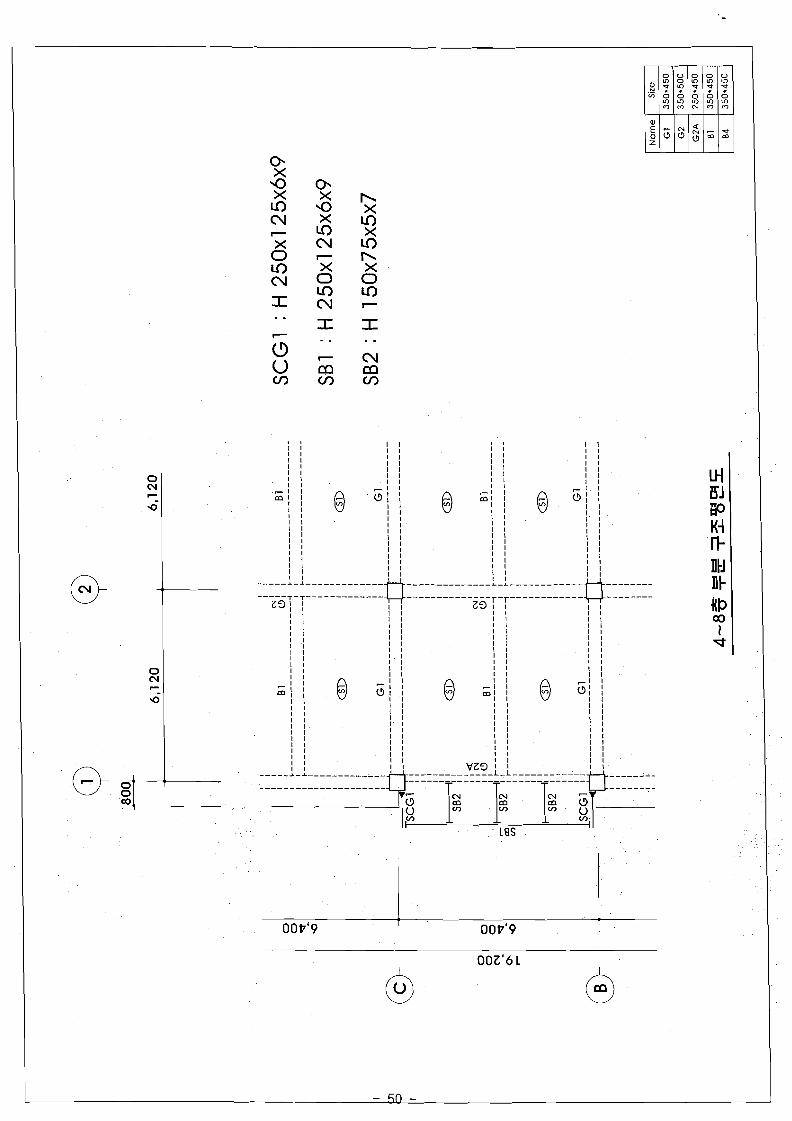
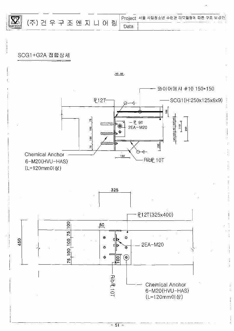
SCG 1 (H:25Ox125x6x9) !
I
! I
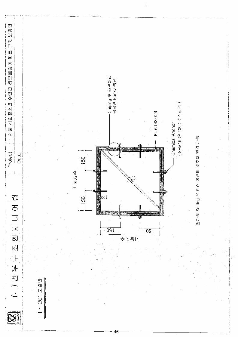
Chemical Anch 6-M20(HVU-HAS)
-- - -
Project hi^ h l 8 l h S +93 219Y12MI m t tX 92P' - -
- - . - - - - - - - L - . I-- - - - , Data
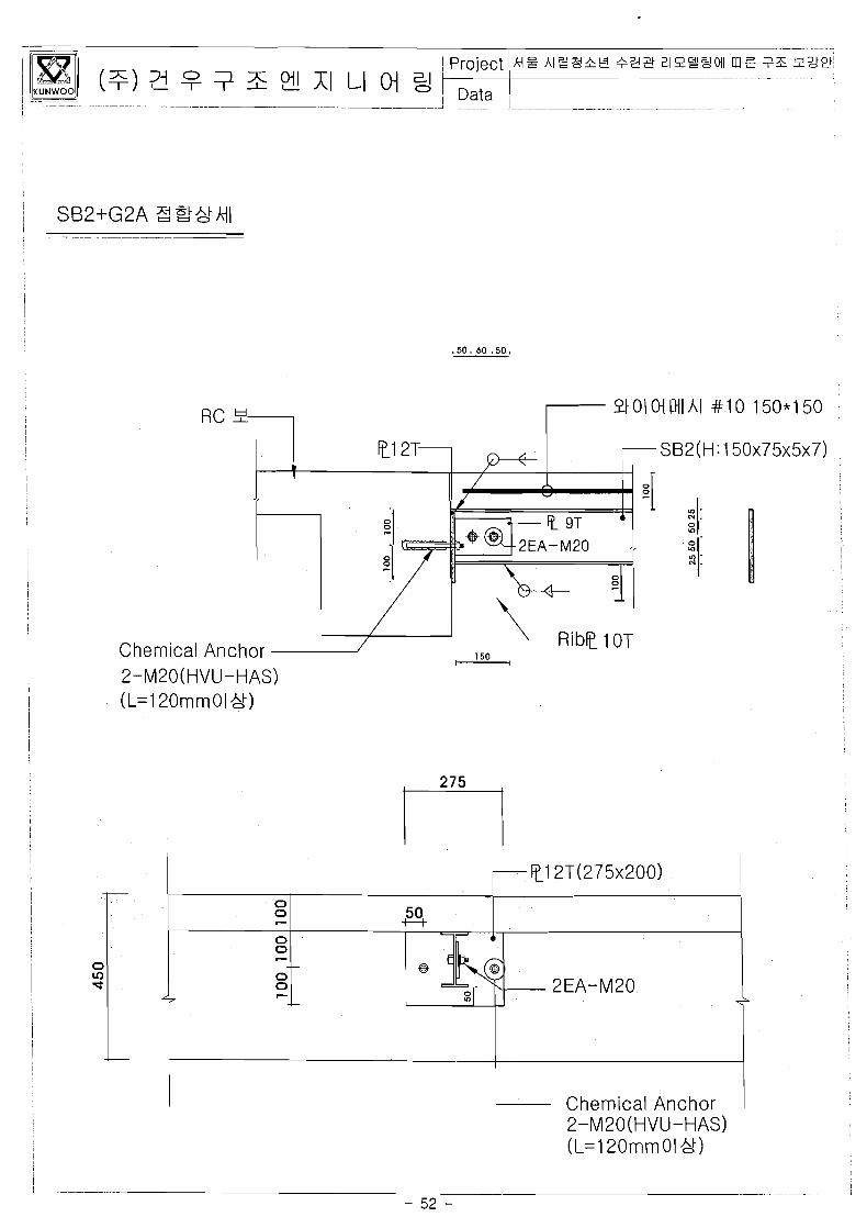
Chemical 2-M20(H
Anchor VU-HAS)
I I
L
2-M20(HVU-HAS) (L=120mniOl
+-
- t1 ZT(275~200)
0 0 - 0 0 - 0 0 -
5 0 -H.
-
0
7
V)
2EA-M20
Chemical Anchor
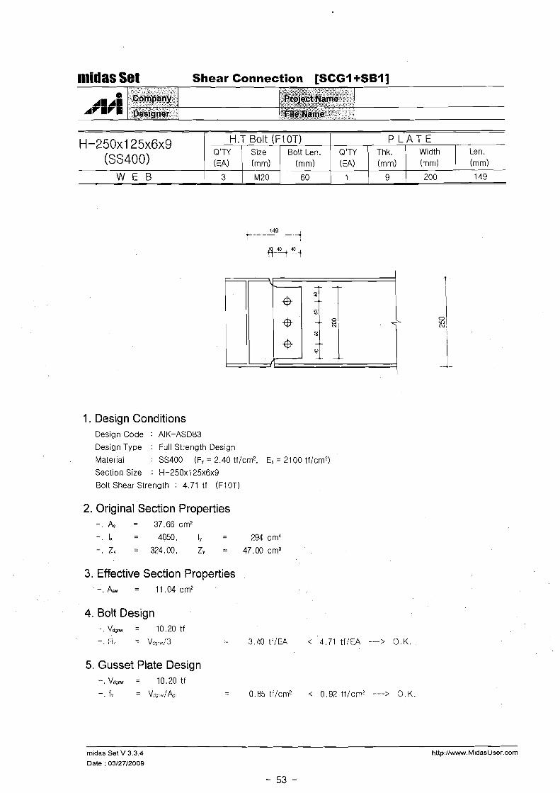
midas Set Shear Connection [SCGI +SBl]
1. Design Conditions Design Code : AIK-ASD83
Design Type : Full Strength Design
Material : SS400 (Fy = 2.40 tf/cm2, Es = 2100 tf/cm2)
Section Size : H-250x125~6~9
Bolt Shear Strength : 4.71 tf (FIOT)
H-250x125~6~9 (SS400)
W E B
2. Original Section Properties - . & = 37.66cm2
-. l x = 4050, Iy - 294 cm4 -
- . Z x = 324.00, Zy = 47.O0cm3
3. Effective Section Properties A = 11.04cm2
4. Bolt Design -.Vdgnw = 10.20tf
- R = v*:.,,/3
H.T Bolt (F1 OT)
5. Gusset Plate Design -.Vdonw = 10.20tf
-. f,; = Vj-slA;;~
P L A T E Q'TY (EA)
3
= 3.40 tf/EA < 4.71 tf/EA ----> O.K.
= 0.85 tf/cm2 i 0.92 t f lcm2 ---> O.K.
Len. (mm)
149
Size (mm)
~ 2 0
midas Set V 3.3.4
Date : 03/27/2009
Width (mm)
200
Bolt Len. (mm)
60
Q'TY (EA)
I
Thk. (mm)
9

nridas Set Shear Connection [SBI +SB21
H - 1 5 0 x 7 5 ~ 5 ~ 7 (SS400)
1. Design Conditions Design Code : AIK-ASD83
Design Type : Full Strength Design
Material : SS400 (Fy = 2.40 tf/cm2, Es = 2100 tf/cm2)
Section Size : H-150x75~5~7
Bolt Shear Strength : 5.70 tf (FIOT)
I I I I I
2. Original Section Properties - . A s = 17.85cm2
- . Ix - - - 666, Iy - 49 cm4
- Z = 88.80, Zv = 13.20 cm3
W E B 1 2 1 M22
3. Effective Section Properties A = 6.30cm2
H.T Bolt (F1 OT)
4. Bolt Design -. Vdenw = 5.82 tf
. R = V,v;-,,/2 = 2.91 tf/EA < 5.70 tf/EA ---> O.K.
P L A T E Q'TY (EA)
60
5. Gusset Plate Design -.Vdonw = 5 .82t f
-. f:. = Vdj-a/ AT, = 0.85 tf/cm2 < 0.92 tf/cm' ---> O.K.
Q'TY Thk. Width LEA) 1 (mm) 1 (mm)
1 8 1 110 209
midas Set V 3.3.4 http://www.MidasUser.com
Date : 03/27/2009
Len. (mm)
Size (mm)
Bolt Len. (mm)
Kunwoo Structural Engineering


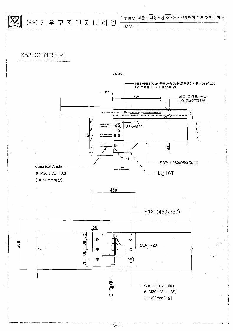
HILTI-RE 500 S3 Y t h t 8 7 0 a & B ~ 2 ~ A M % : H D l 3 @ 2 0 0 ZES'OI L = 120rnrnOIk!)
, I . . . - . . -- - -
0
0
0 V) !I SB2(H:250x250x9x 14)
Chemical Anchor
6-M20(HVU-HAS)
Chemical Anchor
I
6-M20(HVU-HAS)
(L=120mrnOl ",I)
! I
Project -. .. .
M Q A I E S & Y 393 E!IP'2$!011 K t t ?E L220,ti ~ . . . - - !
Data - -~
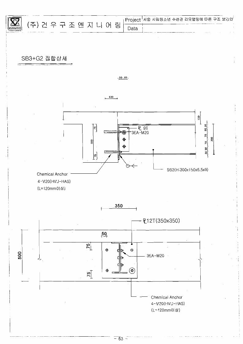
SB2(H:300~150~6.5~9) Chemical Anchor
Chemical Anchor
4-M2O(HVU-HAS)

. . .
+32 21988Ml K I t 75 22e -.-pp...-....-.--.- -~
Data ~ - -- - . . .. -
. . . . . . _ ----p--..-..p- ~ - - ~ ~ .
SB2(H:300~150~6.5~9) Chemical Anchor
Chemical Anchor
4-M20(HVU-HAS)
(L=120mmOl ",t)

Kunwoo Structural Engineering
- 65 -

OOP'P OOP'P OOP'9
bow OOZ'6 L
8 0 0
7
V)
7 CU
m .. = Go -- CU M 2 W l .. .. C C 0 0 ok 9: 0: 70 I I (-1
ii; u Go
cu ;;o M - n 1
O M 3 z 1 M {IN
Kunwoo Structural Engineering
- 68 -
OOP'9 OOP'9 OOV'9
b o e 002'6 L
6 0 0

Kunwoo Structural Engineering

009'9 OOP'P OOP'P
002'61 ,
Q

I OOZC OOZC
OOP9
$0 04 a0 L
-<
ulu - R 5 ?o - . 0
ar I -I
UlO . .
NO JIJ
-L
0J
0 1 I rd
OIN {IN v I
111 0 I nt .- -
5 i i o ?o .$ M $JJ aJ U-I l
X - 3 0 6
sr 6 01 110k <i
.E 110t -0
Ut i i o ; ~ 6 #lr i ,

Iv. 0 3 I Data
Kunwoo Structural Engineering

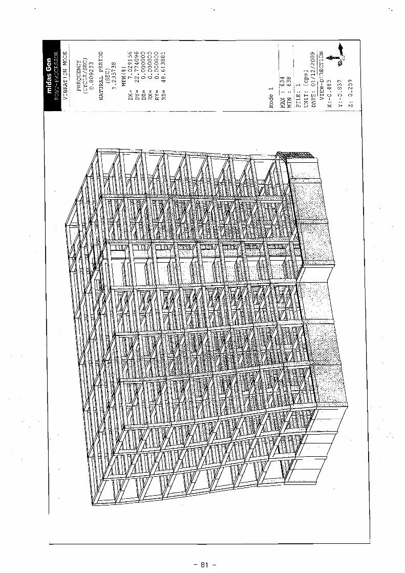
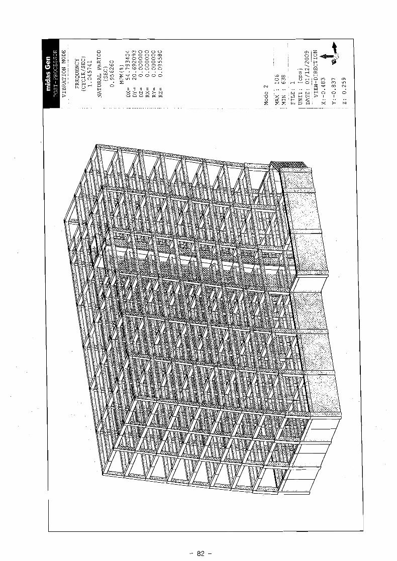
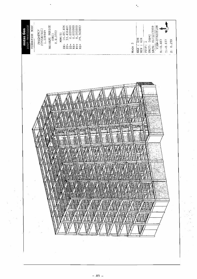
VIBRATION MODE
- - . . . ..- - -
-
FREQUENCY
(CYCLE/SEC)
1.045741
NATURAL PERIOD
(SEC)
0.956260
MPM(%)
DX= 54.793404
DY= 20.692093
DZ=
0.000000
RX=
0.000000
RY=
0.000000
RZ=
0.095580
I ! Mode 2
. .....-
--.
MAX
: 106
MIN
~-
: ...
. 638
. . - - - -. . .
FILE: 1
UNIT:
[cp
s]
DATE: 01/12/2009
.. ....
~
----
-
VIEW-DIRECTION
midas Gen PROJECT TITLE :
Modeling, Integrated Design &Analysis Software htlp:llwww.MidasUser.com midas Gen V 741
Print DateKime : 0111212009 13:20 112

midas Gen PROJECT TITLE :
Modeling, Integrated Design & Analysis Soflware Print DatelTime : 0111212009 13:20 http:llwww.MidasUser.com 212 midas Gen V 741
, Author "
397371 2AtAt';e dPi%71 2AtAF';k
,ye+ ' i " -
*
-~ile L '
1 . 7 1 ~ ( 4 P ~ ~ ~ ) . m g h


BEA
M
DIA
GR
AM
--
MO
MEN
T- y
-
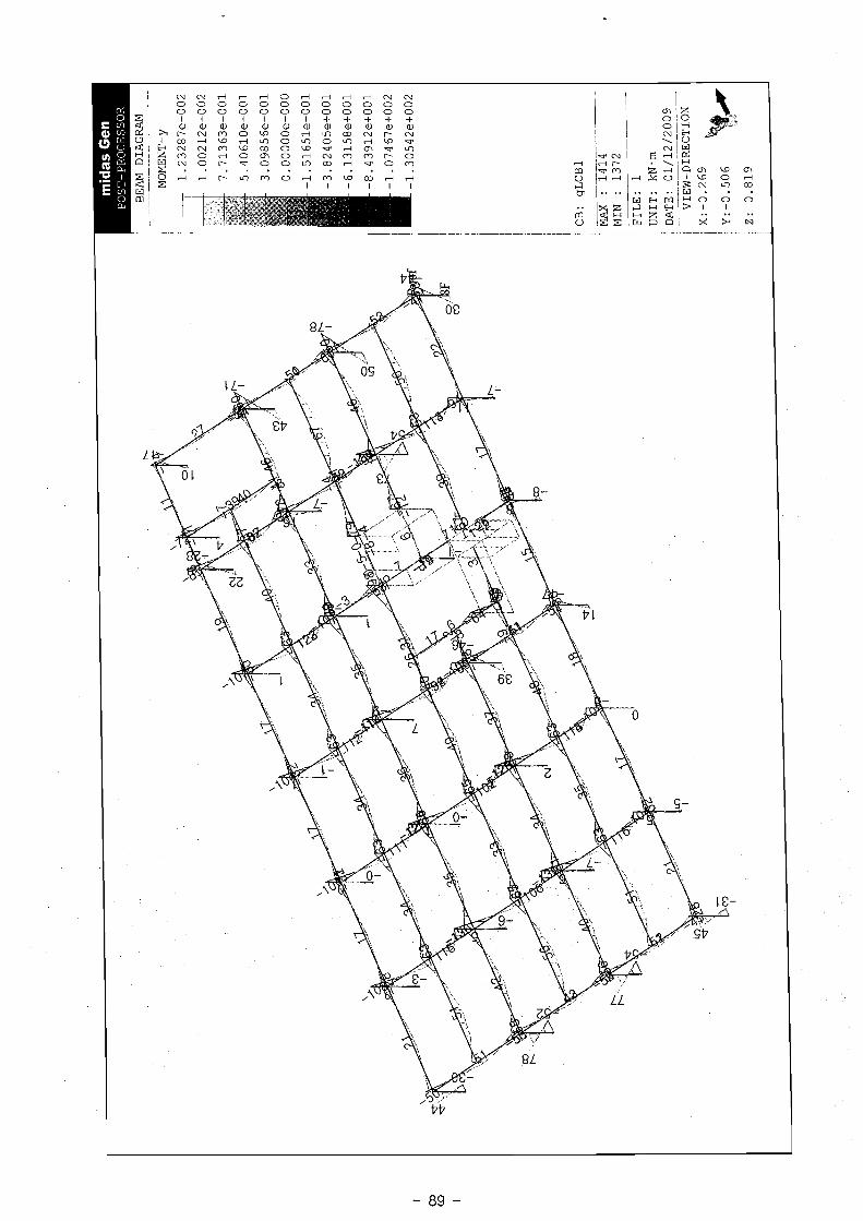
1.2
32
87
et0
02
CB
: g
LC
Bl
MA
X :
14
14
M
IN :
13
72
FIL
E:
1
UN
IT:
kN-m
D
ATE
: 0
1/1
2/2
00
9
_ V
IEW
-DIR
EC
TIO
N

BEAM DIAGRAM
..
-
SHEAR-2
CB:
gLCBl
--
MAX
: 1402
MIN
: 1372
FILE:
1
UNIT:
kN
DATE:
01/12/2009
--
~ ...-.. -
-
VIEW-DIRECTION

BEAM DIAGRAM
-
.
SHEAR-2
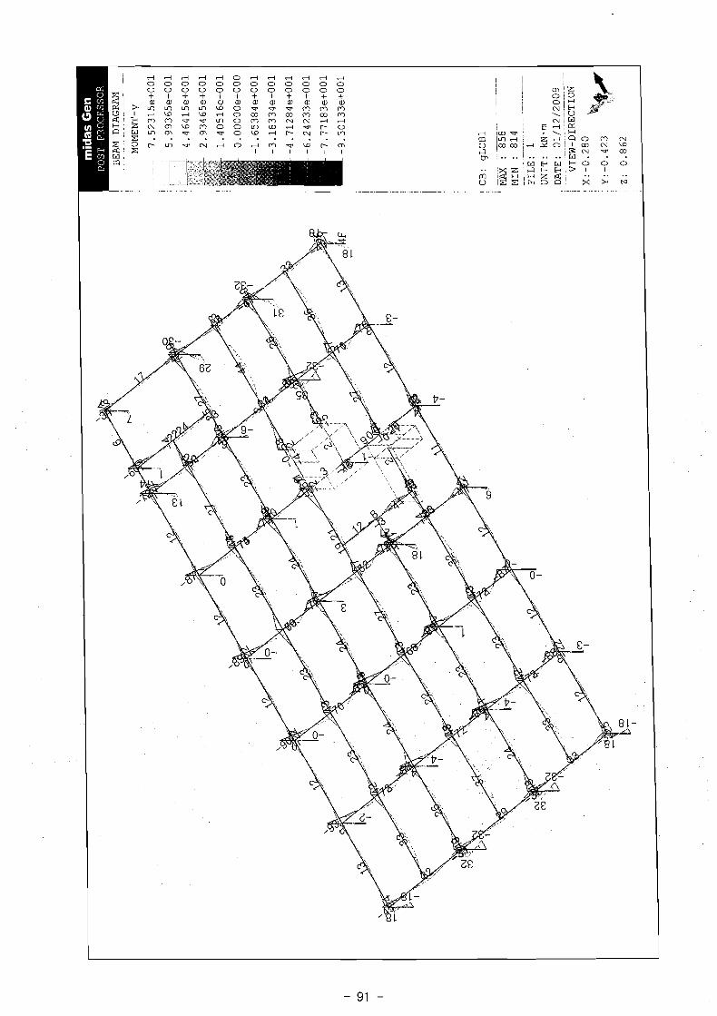
CB: gLCBl
-. -
-.
MA
X : 846
MIN : 814
-
-.
FILE: 1
UNIT: kN
DATE: 01/12/2009
- --
--
- -
--
VIEW-DIRECTION

BEAM DIAGRAM
....
.
...
I
SHEAR-z
CB: gLCBl
.
.
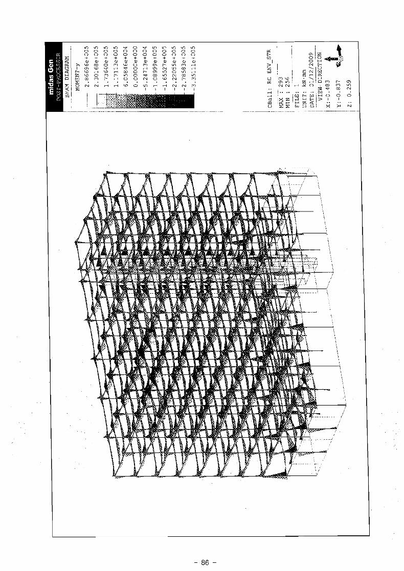
. MAX : 293
MIN : 256
.
.. ...
......
...
FILE: 1
UNIT : kN
DATE: 01/12/2009
- - - -- - -
VIEW-DIRECTION

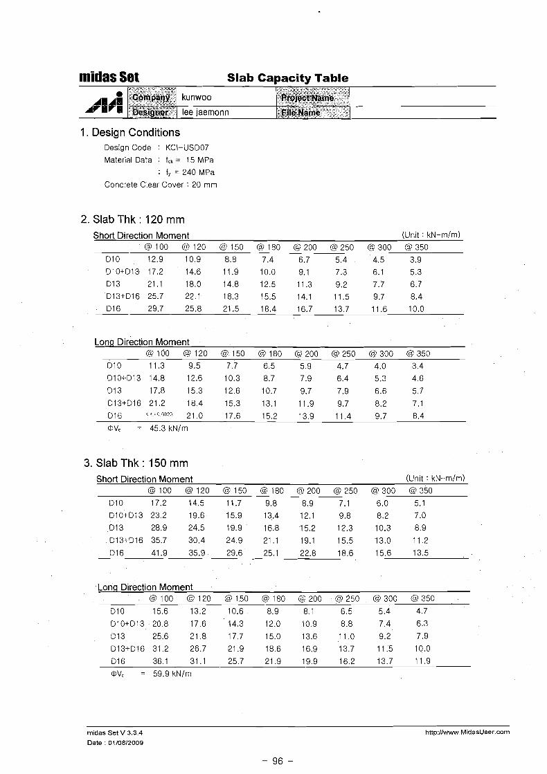
midas Set Slab Cal~acitv Table
1. Design Conditions Design Code : KCI-US007
Material Data : fck = 15 MPa
: f, = 240 MPa
Concrete Clear Cover : 20 mm
2. Slab Thk : 120 mm Short Direction Moment (Unit : k ~ - m / m )
@ l o 0 @ I 2 0 (3150 @I80 (9200 @250 (~2300 @350
Long Direction Moment @ l o o @ I 2 0 @I50 @I80 @200 @250 0 3 0 0 ($350
3. Slab Thk : 150 mm Short Direction Moment (Unit : kN-m/m)
@ l o 0 @ I 2 0 @ I 5 0 @I80 (9200 @250 @300 Q350
Long Direction Moment @I00 @ I 2 0 @I50 @I80 G200 @250 (3300 @350
310 15.6 13.2 10.6 8.9 8.1 6.5 5.4 4.7
D10+Di3 20.8 17.6 14.3 12.0 10.9 8.8 7.4 6.3
213 25.6 21.8 17.7 15.0 13.6 11.0 9.2 7.9
E13+D16 31.2 26.7 21.9 18.6 16.9 13.7 11.5 10.0
21 6 36.1 31.1 25.7 21.9 19.9 16.2 13.7 11.9
0 = 59.9 kN/m
rnidas Set V 3.3.4
Date : 01/08/2009
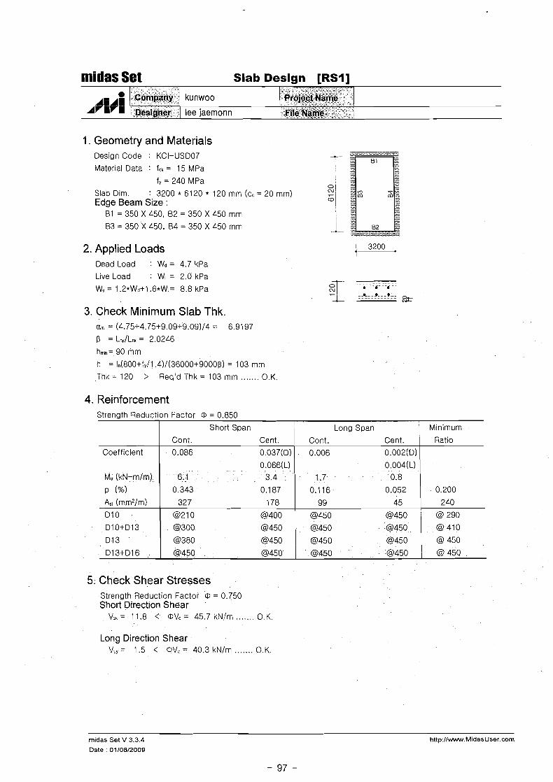
Slab Design [RSI]
AI ~i lee 7
rb :Oesi&er ] lee jaernonn
1. Geometry and Materials Design Code : KCI-USD07 f-
Mater~al Data : fck = 15 MPa I
f, = 240 MPa 0 '
Slab Dlrn. : 3200 * 6120 * 120 rnrn (c, = 20 rnrn) CU' - 1
Edge Beam Size : 61 = 350 X 450, 62 = 350 X 450 rnrn I
63 = 350 X 450. 64 = 350 X 450 rnrn i 2. Applied Loads
Dead Load : Wd = 4.7 kPa
Live Load : WI = 2.0 kPa
Wu = 1.2*Wd+l . ~ * W I = 8.8 kPa
3. Check Minimum Slab Thk. a, = (4.75+4.75+9.09+9.09)/4 = 6.9197
e = Lny/Lnx= 2.0246
hm,n= 90 rnrn
h = ln(800+fy/1 .4)/(36000+9000~) = 103 rnrn
Thk = 120 > Req'd Thk = 103 rnrn ....... O.K.
4. Reinforcement Strength Reduction Factor @ = 0.850
0 I Long Span i Minimum
5. Check Shear Stresses
Coefficient
Strength Reduction Factor @ = 0.750 Short Direct~on Shear
V,,= 11.8 < @ V , = 45.7kNlrn ..... O.K.
Long Direction Shear V,= 1.5 < 0 \Jc=40.3kN/rn ....... O.K.
Cont. Cent.
0.086 O.O37(D)
midas Set V 3.3.4
Date : 01/08/2009
Cont. Cent. Ratio
. 0.006 0.002(D) I
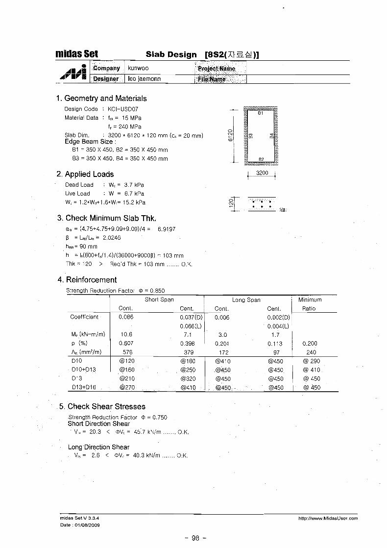
1. Geometry and Materials Design Code : KCI-USD07
Material Data : fck = 15 MPa
f, = 240 MPa Slab Dim. : 3200 * 61 20 * 120 mm (cc = 20 mm) Edge Beam Size :
B1 = 350 X 450, 82 = 350 X 450 mm
B3 = 350 X 450, B4 = 350 X 450 mm
midas Set Slab Design [8S2(Xt S g ) ]
2. Applied Loads ~200- i
Cllfi 1 lrl
Dead Load : Wd = 3.7 kPa
Live Load : WI = 6.7 kPa
W, = 1.2*Wd+1 .6*W1= 15.2 kPa
Company
Dedgner
3. Check Minimum Slab Thk.
hmm= 90 mm
h = 1n(800+fq/l.4)/(36000+9000~) = 103 mm
Thk = 120 > Req'd Thk = 103 mm ....... O.K.
kunwoo
lee jaemonn
4. Reinforcement
Project Name
VlejNpe
5. Check Shear Stresses
Strength Reduction Factor 0 = 0.850
Strength Reduction Factor 0 = 0.750 Short Direction Shear
\IJ, = 20.3 < (DVc = 45.7 kN/m ....... O.K.
Coefficient
Mu (kN-mlm)
P (%)
As! (mm2/m)
D l 0
D l O+D13
D l 3
D l 3+D16
Long Direction Shear V.,= 2.6 < 0V ,=40 .3kN/m ....... O.K.
midas Set V 3.3.4 http://www.MidasUser.com
Date : 01/08/2009
Short Span I I Long Span M~nimum
Cont. Cent. ' Cont. Cent. 1 Ratlo
0.086 O.O37(D)
O.O66(L)
10.6 7.1
0.006 O.OOZ(D) /
O.,O.?(L) ) 3.0
0.607 0.398 0.201 0.1 13 j 0.200
578 379
@I 20 @I 80
@ I 60 @250
@210 @320
@270 @41 0
172 97 240
(3410 0 4 5 0 @ 290
@450
@450 @450
@450 @450 @ 450

1. Geometry and Materials
nlidas Set Slab Design 1% 9 (s E ) ]
Design Code : KCI-US007
Material Data : f,k = 15 MPa
/ rl
fy = 240 MPa Slab Dim. : 3200 * 6120 * 120 mm (cc = 20 mm) Edge Beam Size :
2. Applied Loads 1 3200 4 '
Cok~any -- '
be4jg<ei
Dead Load : Wd = 3.5 kPa
Live Load : WI = 3.0 kPa
Wu = 1.2*Wd+1 . ~ * W I = 9.0 kPa 4 . 6 - 0 9 . A - 3:
3. Check Minimum Slab Thk. am = (4.75+4.75+9.09+9.09)/4 = 6.91 97 I3 = LnylLnx = 2.0246
hmin= 90 mm
h = 1,(800+f,/l.4)/(36000+9000I3) = 103 mm
Thk = 120 > Req'd Thk = 103 mm ....... O.K.
kunwoo
lee jaemonn
4. Reinforcement Strength Reduction Factor 0 = 0.850
. Y v > "
7&$@ct~ame ' I?'* A >
6Ziie tame
5. Check Shear Stresses
Coefficient
Mu (kN-m/m)
0 (%I As, (mmz/m)
D l 0
DlO+D13
013
D13+D16
Strength Reduction Factor 0 = 0.750 Short Direction Shear
V,,= 12.0 < OVc= 45.7 kN/m ....... O.K.
Long Direction Shear V.,= 1.5 < OV,= 40.3kNlm ....... O.K.
Short S ~ a n
Cont. Cent.
midas Set V 3.3.4
Date : 01/08/2009
Long Span
Cont. Cent.
Minimum
Ratio
0.086 0.037(0) ; 0.006 0.002(0),
0 i O.O04(L) / 6.3 0.9 1
0.350 0.21 1
334 20 1
0 2 1 0 @350
@290 @450
@370 @450
@450 @450
0.1 18 0.060 1 0.200
101 51 I 240
@450 (3450
@450 @450
@ 290
@ 410
(3450 @450 , @ 450
(3450 I
0 4 5 0 I @ 450

midas Set Slab Design [I F(& Lt 'St)]
1. Geometry and Materials Design Code : KCI-US007 -- Material Data : fck = 15 MPa
f, = 240 MPa Slab Dim. : 3200 * 6120 * 120 mm (cc = 20 mm) Edge Beam Size :
81 = 350 X 450, B2 = 350 X 450 mm
83 = 350 X 450, 64 = 350 X 450 mm -.-- -- 2. Applied Loads
Dead Load : Wd = 7.0 kPa
Live Load : WI = 4.0 kPa
WU = 1.2*Wd+1 . ~ * W I = 14.8 kPa
3. Check Minimum Slab Thk. a, = (4.75+4.75+9.09+9.09)/4 = 6.91 97
!.3 = LnJLnx = 2.0246
hm,n= 90 mm
h = ln(800+fy/l.4)/(36000+9000!.3) = 103 mm
Thk = 120 > Req'd Thk = 103 mrn ....... O.K.
4. Reinforcement Strength Reduction Factor 0 = 0.850
I
Short Span I Long Span ; Minimum
Coeff~clent
Strength Reduction Factor 0 = 0.750 Short Direction Shear
V.,= 19.8 < OVc= 45.7kN/m .... ..O.K.
Cont. Cent. i Cont. Cent. Ratlo
0.086 0.037(D) 0.006 0.002(D) :
&I (mm2/m)
D l 0
D10+D13
D l 3
D l 3+D16
Long Direction Shear V.,= 2.5 < OV,.=40.3kN/m ....... O.K.
rnidas Set V 3.3.4
Date : 0110812009
5. Check Shear Stresses
564 316 1 @I 20 @220
@ I 70 @310
@220 @390
@280 @450
168 79 1 240
(3420 @450
@450 63450
@450 @450
@450 @450
@ 290
@ 410
@ 450
@ 450

midas Set Slab Design [I F-S4-% el]
1. Geometry and Materials Design Code : KCI-USD07 - Material Data : fct = 15 MPa
f, = 240 MPa Slab Dim. : 3200 * 61 20 * 150 mm (cc = 20 mm) Edge Beam Size :
61 = 350 X 450, 62 = 350 X 450 mm
63 = 350 X 450. 64 = 350 X 450 mm I! 2. Applied Loads 3200 4 1
Dead Load : Wd = 6.5 kPa
Live Load : WI = 3.0 kPa
Wu = 1.2*Wd+1 .6*W1= 12.6 kPa
3. Check Miniml-~m Slab Thk. Urn = (2.39+2.39+4.57+4.57)/4 = 3.4816
[3 = Lnq/Lnx = 2.0246
hrnin= 90 mm
h = In(800+f,/l .4)/(36000+9000B) = 103 mm
Thk=150 > Req'dThk=103mm ....... O.K.
4. Reinforcement Strenath Reduction Factor 0 = 0.850 -
5. Check Shear Stresses
Short Span
Coefficient
Strength Reduction Factor 0 = 0.750 Short Direction Shear
V,,= 16.9 < Q V c = 60.2 kN/m ....... O.K.
I
Long Span ( Minimum
Long Direction Shear Vliy = 2.2 < Q\Jr = 54.9 kN/m .. . . . . . 0. K.
Cont. Cent.
0.086 0.037(D)
midas Set V 3.3.4 http:llwww.MidasUser.com
Cont. Cent. I Ratio
0.006 0.002(D) 1
Date : 01108/2009

1. Geometry and Materials
midas Set Slab Design [I F-S5-5 el]
Design Code : KCI-USD07 t -- Material Data : fck = 15 MPa
f, = 240 MPa 0
Slab Dim. : 4500 * 61 20 * 150 mm (cc = 20 mm) (D Edge Beam Size :
81 = 350 X 450, 82 = 350 X 450 mm
83 = 350 X 450, 64 = 350 X 450 mm
* AM
2. Applied Loads ----A Dead Load : Wd = 5.1 kPa
Company
~e,gn&,
Live Load : WI = 3.0 kPa .................................. of- . . . . . .r ..............
WU = 1.2*Wd+1 .6*W1= 10.9 kPa E .
....... 51 .L, 1 . " . . . . ..e .................. D ................................. *- 3. Check Minimum Slab Thk.
a, = (2.39+2.39+3.25+3.25)/4 = 2.8212
13 = LnyILnx = 1.3904
hmin= 90 mm
h = In(800+f,/1 .4)/(36000+9000~) = 1 16 mm Thk=150 > R e q ' d T h k = l 1 6 m m ....... O.K.
kunwoo
lee jaemonn
4. Reinforcement
P~oject N'anie
Eila Narme
Strength Reduction Factor Q, = 0.850 I Short Span Long Span / Minimum
Cont. Cent. 1 Cont. Cent. 1 Ratio
5. Check Shear Stresses
Coefficient
Mu (k~ -m/m)
p (%I A, (mm2/m)
Strength Reduction Factor Q, = 0.750 Short Direction Shear
....... Vd,= 17.9 < @ V c = 602kN:m O.K.
Long Direction Shear V,,, = 6.6 < Q,V, = 54.9 kN/m ....... O.K.
0.072 0.029(D) ' 0.01 9 0.008(D) 1
midas Set V 3.3.4
Date : 0110812009
O.O47(L) 13.6 7.0
0.442 0.224
554 280
O.O13(L)
6.9 3.6
0.258 0.134 0.200
298 155 I 300

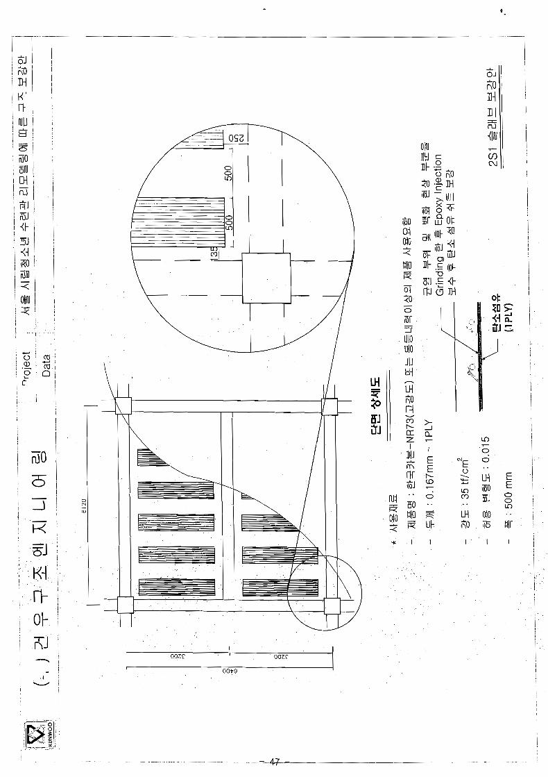
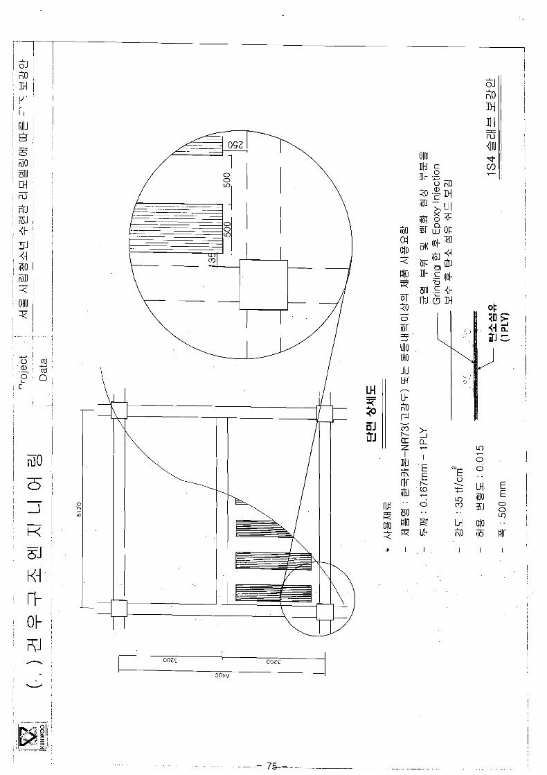
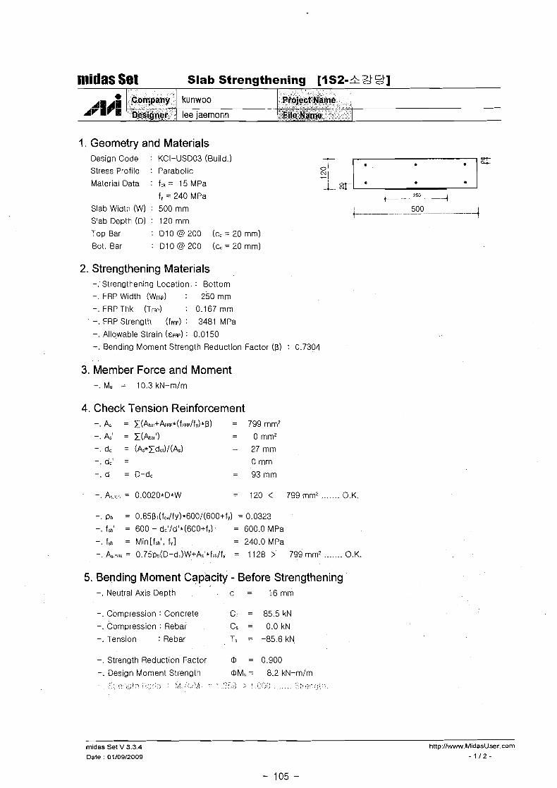
midas Set Slab Strengthening [8S2-2 gC9]
1. Geometry and Materials
A #:#I
Design Code : KCI-USD03 (Build.)
Stress Profile : Parabolic
Material Data : fck = 15 MPa
f, = 240 MPa
Slab Width (W) : 500 mm
Slab Depth (Dl : 120 mm
Top Bar : D l 0 @ 200 (cc = 20 mm)
Bot. Bar : D l 0 @ 200 (cc = 20 mm)
2. Strengthening Materials -. Strengthening Location : Bottom
-. FRP Width (WFRP) : 250 mm
-. FRP Thk (TFRP) : 0.167 mm
-. FRP Strength (~FRP) : 3481 MPa
-. Allowable Strain (EFRP) : 0.0150
-. Bending Moment Strength Reduction Factor (p) : 0.7304
Company ( kunwoo
Designer 1 lee jaernonn
3. Member Force and Moment -. Mu = 10.6 kN-m/m
Project yame
File Name
4. Check Tension Reinforcement -. As = t ( A b a # + & ~ ~ * ( f ~ R ~ / f y ) * [ 3 ) = 799 mm2
-.As' = t(Abar') = omm2
-. dc = (As*tdc3/(As) = 27mm
-. dc' = 0 mm
-. d = D-dc = 93mm
-. As,:? = 0.0020*D*W = 120 < 799 mm? ...... O.K.
-. pb = 0.85p1(fcr/f~)*600/(600+f~) = 0.0323 -. fsbl = 600 - dc'/d'*(600+fy) = 600.0 MPa
-. fsb = Min[fsb0, fY1 = 240.0 MPa
-. As-.aq = 0.75pc(D-d-.)W+As'*fS~:lfY = 1 128 > 799 mm? ....... O.K.
5. Bending Moment Capacity - Before Strengthening -. Neutral Axis Depth c = 1 6 m m
-. Compression : Concrete Cc = 85.5 kN
-. Compression : Rebar CS = 0.0kN
-. Tension : Rebar Ts = -85.6 kN
-. Strength Reduction Factor @ = 0.900
-. Design Moment Strength DM, = 8.2 kN-mlm .... >:i .-?..,,, ;'> C,.*:..\ ..c:i . . ,..,,. ,.
, ; , . : : , . , 7 ... , - .cs . ,.> :. . .;;.,;> . .. . , . . :.:?:;>r:c)2s: ,;: .,. .. , .
midas Set V 3.3.4
Date : 0110912009

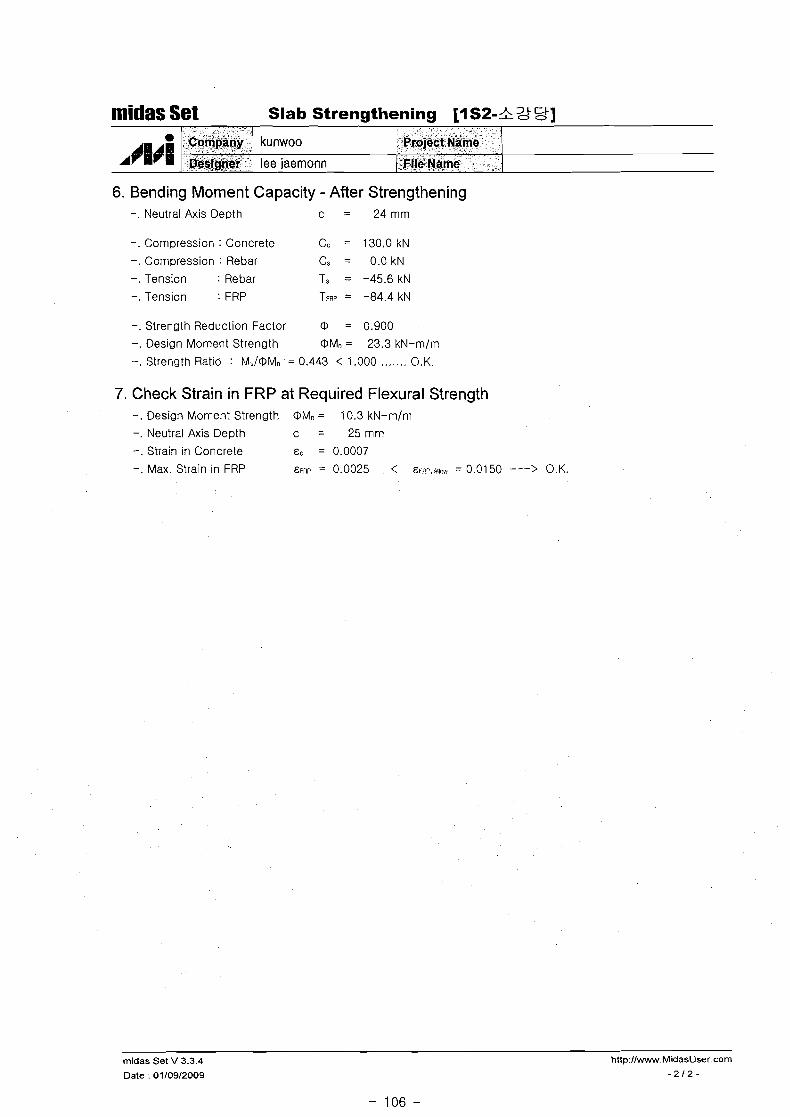
6. Bending Moment Capacity - After Strengthening
midas Set Slab Strengthening [8S2-S =&!I
-. Neutral Axis D e ~ t h c = 24mm
e
A~~~~
-. Compression : Concrete Cc = 130.0 kN
-. Compression : Rebar Cs = 0.0 kN
-. Tension : Rebar Ts = -45.6 kN
-. Tension : FRP TFRP = -84.4 kN
-. Strength Reduction Factor O = 0.900
-. Design Moment Strength OMn = 23.3 kN-m/m
-. Strength Ratio : MJOMn = 0.456 < 1.000 ....... O.K.
hCompany
&signer
7. Check Strain in FRP at Required Flexural Strength -. Design Moment Strength OMn = 10.6 kN-m/m
-. Neutral Axis Depth c = 24mm
-. Stra~n in Concrete EC = 0.0007
-. Max. Stra~n in FRP E k h ~ = 0.0027 < E I Z J , ~ ~ ~ . . ~ = 0.0150 ---> O.K.
midas Set V 3.3.4 http:llwww.MidasUser.com
Date : 0110912009 -212-
kunwoo
lee jaernonn
* - . A s " >
," ff@j&ham& : . e<
' ~ i l e pa%$ "
1. Geometry and Materials
nlidas Set Slab Strengthening [I S2-& Lt St]
Design Code : KCI-USDO3 (Build.)
Stress Profile : Parabolic Si 1 Material Data : fck = 15 MPa 0T -1. E L r3
f, = 240 MPa +. ---E 4 Slab Width (W) : 500 mm t I 500 . - I
-t Slab Depth (Dl : 120 mm
Top Bar : D10@200 ( c c = 2 0 m m )
Bot. Bar : D10@200 ( c c = 2 0 m m )
A+W~
2. Strengthening Materials -. Strengthening Location : Bottom
-. FRP Width (WFRP) : 250 mm
-. FRP Thk (TFRP) : 0.167mm
-. FRP Strength (~FRP) : 3481 MPa
-. Allowable Strain (GFRP) : 0.01 50 -. Bending Moment Strength Reduction Factor (8) : 0.7304
3. Member Force and Moment
, Company
DeGgppi.
4. Check Tension Reinforcement -. As = t(Abar+&R~*(fF~~/fy* = 799 mm2
-. As' = t(Abar') = 0 mm2
-. dc = (As*Edc~)/(As) = 27mm -.dc' = 0 mm
-. d = 0-dc = 93mm
-. As.-, = 0.0020*D*W = 120 < 7 9 9 m d ....... O.K.
kunwoo
lee iaemonn
-. ~b = 0.85~1(f~Jfy)*600/(600+f~) = 0.0323
-. fsb' = 600 - dc'/d'*(600+f,) = 600.0 MPa
-. fsb = Min[fsbt. fy l = 240.0 MPa
-. As-a = 0.75~o(D-d:)W+A~'* f~~/ f~ = 11 28 > 799 mm2 ....... O.K.
F-ioiect'~&me " -"
'"<iifi&$i&ew -
5. Bending Moment Capacity - Before Strengthening -. Neutral Axis Depth c = 1 6 m m
-. Compression : Concrete Cc = 85.5 kN
-. Compression : Rebar Cs = 0.0 kN
-. Tension : Rebar Ts = -85.6 kN
-. Strength Reduction Factor O = 0.900
-. Design Moment Strength OM, = 8.2 kN-m/m !.', ;<;.;.,,, ; :.;;:,,:> ;, ,, <><.,;>: . :,.:, . . . . . , . . . . . . . . . , . .... ~,?,
. ..;.;
midas Set V 3.3.4 http://w.MidasUser.com
Date : 01/09/2009 - 1 1 2 -
midas Set Slab Strengthening [I S2-& 511
6. Bending Moment Capacity - After Strengthening -. Neutral Axis Depth c = 24mm
- - - -
-. Compression : Concrete C, = 130.0 kN
-. Compression : Rebar Cs = 0.0 kN
-. Tension : Rebar Ts = -45.6 kN
-. Tension : FRP TFRP = -84.4 kN
I)
dvHrE
-. Strength Reduction Factor @ = 0.900
-. Design Moment Strength @Mn = 23.3 kN-mlrn
-. Strength Ratio : M.i@Mn = 0.443 < 1.000 ....... O.K.
7. Check Strain in FRP at Required Flexural Strength -. Design Moment Strength @Mn = 10.3 kN-mlm
-. Neutral Axis Depth c = 25mm
-. Strain in Concrete E C = 0.0007
-. Max. Strain ~n FRP E ~ h p = 0.0025 < E ~ ~ E , & I I . W = 0.01 50 ---> 0 K.
~ o m ~ a n g
'Geq[gomf "
midas Set V 3.3.4 http://www.MidasUser.com
Date : 01/09/2009 -212-
kunwoo
lee jaemonn
Rroject "me
- FileName - *

midas Set Slab Strengthening CIS5-+ XI+?]
1. Geometry and Materials Design Code : KCI-USD03 (Build.)
Stress Profile : Parabolic
Material Data : fck = 15 MPa
f, = 240 MPa Slab Width (W) : 500 mm
Slab Depth (Dl : 150 mm
Top Bar : D l 0 @ 200 (cc = 20 mm)
Bot. Bar : D l 0 @ 200 (cc = 20 mm)
2. Strengthening Materials -. Strengthening Location : Bottom
-. FRP Width (WFRP) : 250 mm
-. FRP Thk (TFRP) : 0.167 mm
-. FRP Strength (~FRP) : 3481 MPa
-. Allowable Strain (EFRP) : 0.0150
-. Bend~ng Moment Strength Reduction Factor (0) : 0.7304
3. Member Force and Moment -. Mu = 13.6 kN-m/m
4. Check Tension Reinforcement -.As = z ( A b a r + k f l ~ * ( f ~ ~ ~ / f y ) * D ) = 621mm2
-. As' = z(Aba,') = 178mm2
-. dc = (As*Edc~)/(As) = 7 mm -.dc' = 25 mm
-. d = D-dc = 143 mm
-. As.n?in = 0.0020*D*W = 150 < 621 mm' ....... O.K.
-. Pb = 0.85~1(fck/fy)*600/(600+fy) = 0.0323 -. fsbl = 600 - dc1/d'*(600+fY) = 433.9 MPa
-. fsb = Min[fsbl, f y l = 240.0 MPa
-. As-% = 0.75pt(D-d )W+Ar'*fs~/fy = 1907 > 621 mm2 ....... O.K.
5. Bending Moment Capacity - Before Strengthening -. Neutral Axis Depth c = 16mm
-. Compression : Concrete Cc = 85.7 kN
-. Compression : Rebar Cs = 0.0 kN
-. Tension : Rebar Ts = -85.6 kN
-. Strength Reduction Factor @ = 0.900
-. Design Moment Strength @Mn = 10.5 kN-m/m < > . ? ,. .;:+b? ;;;::< ;,.. . :,i ;:'<;;>,; - : :.;:::/ .;, ; .',..".!\ . . .-;:;r;: :;,<<;. . , \ . , . * : ...,.., '?
:: ::.#> ,->,-<! i? , ... ;ci ....... ..,;..,> : > + < . :
midas Set V 3.3.4 http://www.MidasUser.com
Date : 01/09/2009 -112-

midas Set Slab Strengthening [I S5-+ X t f q] I I I I
6. Bending lbloment Capacity - After Strengthening -. Neutral Axis Depth c = 2 6 m m
AHA; ArmPm
-. Compression : Concrete Cc = 139.6 kN
-. Compression : Rebar Cs = 4.6 kN
-. Tension : Rebar Ts = -42.8kN
-. Tension : FRP TFRP = -101.3 kN
kunwoo
lee jaemonn
Company
Designer
-. Strength Reduction Factor 0 = 0.900
-. Design Moment Strength 0Mn = 34.0 kN-m/m
-. Strength Ratio : Mii/OMn = 0.400 < 1.000 ....... O.K.
Project Name
File' Name
7. Check Strain in FRP at Required Flexural Strength -. Design Moment Strength 0Mn = 13.6 kN-m/m
-. Neutral Axis Depth c = 2 7 m m
-. Strain in Concrete EC = 0.0006
-. Max. Straln in FRP EFRP = 0.0026 < EW;..A~I~ = 0.0150 ---> O.K.
midas Set V 3.3.4 http://www.MidasUser.com
Date : 01/09/2009 - 2 1 2 -
midas Set , "
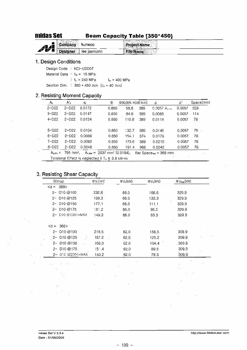
Beam Capacity Table [350*450] , + - " -%
a CB'bpany kunwoo ,ProieBZ Name C " "
1 ~2s:signer leejaernonn Fil,e*Natpe f
1. Design Conditions Design Code : KCI-lJSD07
Material Data : fck = 15 MPa
: f, = 240 MPa fYs = 400 MPa
Section Dim. : 350 * 450 mm (cc = 40 mm)
2. Resisting Moment Capacity A3 Ats EI O OM,(kN.m)d(mm) p p ' Space(mm1
2-D22 2-D22 0.0172 0.850 58.6 389 0.0057 A:.,<:::,; 0.0057 229
As.m,n = 795 mm2, Asrnax = 2637 mm2 (0.0194). Bar Spacem," = 368 mm
Torsional Effect is nealected if T, 5 3.8 kN-m
3. Resisting Shear Capacity Stirrup OV,(kNI @Vc(kN) OVs(kN) OVrnax(kN)
midas Set V 3.3.4 http://www.MidasUser.com
Date : 01/09/2009
- 109 -
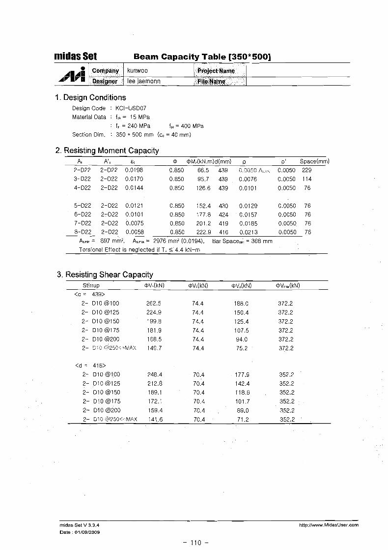
niidas Set Beam Capacity Table [350*500]
1. Design Conditions
1 I 1
Design Code : KCI-US007
Material Data : fck = 15 MPa
: f, = 240 MPa fys = 400 MPa
Section Dim. : 350 * 500 mm (cc = 40 mm)
2. Resisting Moment Capacity A, A's &I O OM,(kN.m)d(mm) p p ' Space(mm1
2-022 2-022 0.0198 0.850 66.5 439 C,.?fi5C A. 0.0050 229
3-022 2-022 0.0170 0.850 96.7 439 0.0076 0.0050 114
Company
~esinner
8-022 2-022 0.0058 0.850 222.9 416 0.0213 0.0050 76
A m l n = 897 mm2, As.max = 2976 mm2 (0.0194). Bar Space,,, = 368 mm
Torsional Effect is neglected if T, S4 .4 kN-m
kunwoo
lee iaernonn
3. Resisting Shear Capacity Stirrup @V:l(kN) OVc(kN) OVs(kN) OV,,(kN)
Project Name
f iieName
rnidas Se t V 3.3.4 http://www.MidasUser.corn
Date : 01/09/2009

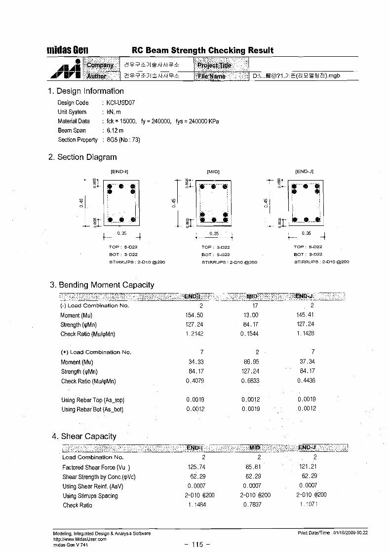
midas Gen RC Beam Strength Checking Result
1. Design Information Design Code : KCI-USD07
Unit System : kN, m
Material Data : fck = 15000, fy = 240000, fys = 240000 KPa Beam Span : 6.12 m
Section Property : RGI (No : 65)
2. Section Diagram
[END-I] [MI Dl [END-J]
TOP ' 5-D22 TOP : 3-D22 TOP. 5-D22
BOT : 3-D22 BOT : 5-D22 BOT 34222
STIRRUPS 2-Dl0 a 2 0 0 STIRRUPS : 2-Dl0 a 2 0 0 STIRRUPS 2-Dl0 a 2 0 0
3. Bending Moment Capacity
L- --w-
- - END-I. ".'
- - . MID . END.J--' - 1 -
(-) Load Combination No.
Moment (Mu)
Strength (qMn)
Check Ratio (MulqMn)
(+) Load Combination No.
Moment (Mu) Strength (qMn) Check Ratio (MulqMn)
Usiqg Rebar Top (As-top)
Usiqg Rebar Bot (As-bot)
4. Shear Capacity - - . - - - - - - - -
. . -- . _ - - - -. END-I MID END-J I -- Load Combination No. 2 2 2
Factored Shear Force (Vu ) 86.69 84.67 72.89
Shear Strength by Conc.(cpVc) 62.29 65.49 62.29
Using Shear Reinf. (AsV) 0.0007 0.0007 0.0007
Using Stirrups Spacing 2-010 @200 2-Dl0 @200 2-Dl0 @200
Check Ratio 0.7918 0.7355 0.6657
Modeling, Integrated Design &Analysis Software Print Datemime : 0111012009 00:17 http:l/www.MidasUser.com midas Gen V 741
- 111 -

RC Beam Strength Checking Result
1. Design Information
e 11.1
AVRy1
Design Code : KCI-USD07
Unit System : kN, m Material Data : fck = 15000, fy = 240000, fys = 240000 KPa
Company
Author-
Beam Span : 6.4 m
?1??3;312hthtFn Project
21??3;31Qhtht8& File Nal
Section Property : RG2 (No : 66)
2. Section Diagram
[END-I] [MIDI [END-J]
TOP 8-D22 TOP 3-D22 TOP 8-D22
BOT 3-D22 BOT 8-D22 BOT 3-D22
STIRRUPS 2-Dl0 @200 STIRRUPS 2-Dl0 a 2 0 0 STIRRUPS 2-Dl0 a 2 0 0
3. Bending Moment Capacity
(-) Load Combination No.
Moment (Mu)
Strength (qMn)
Check Ratio (MulqMn)
(+) Load Combination No.
Moment (Mu)
Strength (qMn)
Check Ratio (MulqMn)
Using Rebar Top (As-top)
Using Rebar Bot (As-bot)
4. Shear Capacity
Load Combination No. 2 2 2
Factored Shear Force (Vu ) 120.99 97.29 118.84
Shear Strength by Conc.(qVc) 69.96 69.96 69.96
Using Shear Reinf. (AsV) 0.0007 0.0007 0.0007
Using Stirrups Spacing 2-Dl0 @200 2-010 @200 2-010 @200
Check Ratio 0.9838 0.7911 0 9664
Modeling, Integrated Design & Analysis Software http:llwww.MidasUser.com rnidas Gen V 741 - 112 -
Print Datemime : 0111012009 00:17

1. Design Information Design Code : KCI-USD07
Unit System : kN, m Material Data : fck = 15000, fy = 240000, fys = 240000 KPa Beam Span : 6.12 m Section Property : RBI (No : 68)
niidas Gea RC Beam Strength Checking Result
2. Section Diagram
CC A g ~ i
AVBrd
[END-I] [MI Dl
TOP : 5-D22
BOT : 3-D22
Cwpany
Agtpor
TOP : 3-D22
BOT : 5-D22
[END-J]
~ ? ? Z S J I Q A ~ A I F &
~ P ? Z J I P A ~ A ~ F &
TOP: 5-D22
BOT : 3-D22
STIRRUPS : 2-Dl0 a200 STIRRUPS : 2-Dl0 a200 STIRRUPS : 2-Dl0 a200
3. Bending Moment Capacity
Pro@w 'iftle
"File-Nape
(-) Load Combination No.
Moment (Mu)
Strength (qMn)
Check Ratio (MulqMn)
D.\ ... E @ ? I . J I Z ( Z I ~ Y ~ ~ ) . ~ ~ ~
(+) Load Combination No.
Moment (Mu)
Strength (pMn)
Check Ratio (MulpMn)
Using Rebar Top (As-top)
Using Rebar Bot (As-bot)
4. Shear Capacity I--
-- END-I 'MID END-J
1
--. -. . - - - - - - - - - Load Combination No.
Factored Shear Force (Vu )
Shear Strength by Conc.(qVc)
Using Shear Reinf. (AsV)
Using Stirrups Spacing
Check Ratio
Modeling, Integrated Design &Analysis Software http://www.MidasUser.com midas Gen V 741 - 113 -
Print Daterrime : 01/10/2009 00:17

midas Gen RC Beam Strength Checking Result
1. Design Information Design Code : KCI-USD07 Unit System : kN, m Material Data : fck = 15000, fy = 240000, fys = 240000 KPa Beam Span : 6.4 m
Section Property : 8G3 (110 : 71)
- -
2. Section Diagram
e
A~~~~
[END-I]
TOP : 8-D22 TOP: 3-D22
BOT : 3-D22 BOT : 8-D22
STIRRUPS : 2-Dl0 a 2 0 0 STIRRUPS : 2-Dl0 (3200
Cdmpany
'~uthor
[END-J]
TOP : 8-D22
BOT : 3-D22
STIRRUPS : 2-Dl0 a 2 0 0
3 8 ? 3 3 1 4 h t h t 8 &
3 8 ? 3 3 1 % h t h t 8 &
3. Bending Moment Capacity
(-) Load Combination No.
Moment (Mu) Strength (qMn)
Check Ratio (MulqMn)
i)r~jq.ct Title
Fileaame
(+) Load Combination No.
Moment (Mu) Strength (qMn)
Check Ratio (MulqMn)
D:\ ... @@?I .3Ie(?I engP) .mgb
Using Rebar Top (As-top) Using Rebar Bot (As-bot)
4. Shear Capacity
Load Combination No.
Factored Shear Force (Vu )
Shear Strength by Conc.(qVc) Using Shear Reinf. (AsV)
Using Stirrups Spacing Check Ratio
Modeling, Integrated Design 8 Analysis Software http:llwww.MidasUser.com midas Gen V 741 - 114 -
Print Daterrime : 0111012009 00:22
nlidas Gen RC Beam Strength Checking Result
1. Design Information Design Code : KCI-USD07 Unit System : kN, m
Material Data : fck = 15000, fy = 240000, fys = 240000 KPa Beam Span : 6.12 m
Section Property : 8G5 (No : 73)
2. Section Diagram
[END-I] [END-J]
TOP : 5.~322 TOP : 3-D22 TOP : 54322
BOT : 3-D22 BOT : 5.D22 BOT : 3.~322
STIRRUPS : 2-Dl0 (3200 STIRRUPS : 2-Dl0 (3200 STIRRUPS : 2-Dl0 (3200
3. Bending Moment Capacity
(-) Load Combination No.
Moment (Mu)
Strength (pMn) Check Ratio (MulpMn)
(+) Load Combination No.
Moment (Mu)
Strength (pMn)
Check ~ a t i o (MulpMn)
Using Rebar Top (As-top) 0.0019 0.0012 0.0019
Using Rebar Bot (As-bot) 0.0012 0.0019 0.0012
4. Shear Capacity
Load Combination No.
Factored Shear Force (Vu )
Shear Strength by Conc.(pVc)
Using Shear Reinf. (AsV)
Using Stirrups Spacing
Check Ratio
Modeling, Integrated Design &Analysis Software Print Daterrime : 01/10/2009 00:22 http://www.MidasUser.com midas Gen V 741 - 115 -

midas Gen RC Beam Strength Checking Result
1. Design Information Design Code : KCI-USD07
Unit System : kN, m
Material Data : fck = 15000, fy = 240000, fys = 240000 KPa Beam Span : 6.12 m
Section Property : 882 (No : 70)
2. Section Diagram
[END-I] [END-J]
TOP : 5-D22
BOT : 3-D22
STIRRUPS : 2-Dl0 a200
TOP : 5-D22
BOT : 3-D22
STIRRUPS : 2-Dl0 a200
TOP : 3-D22
BOT : 5-D22
STIRRUPS : 2-Dl0 a 2 0 0
3. Bending Moment Capacity
(-) Load Combination No.
Moment (Mu)
Strength (pMn)
Check Ratio (MuIpMn)
(+) Load Combination No.
Moment (Mu) Strength (pMn)
Check Ratio (MulpMn)
Using Rebar Top (As-top)
Using Rebar Bot (As-bot)
4. Shear Capacity
Load Combination No. 2 2 2
Factored Shear Force (Vu ) 133.78 95.97 135.92
Shear Strength by Conc.(pVc) 62.29 62.29 62.29
Using Shear Reinf. (AsV) 0.0007 0.0007 0.0007
Using Stirmps Spacing 2-Dl0 @200 2-Dl0 @200 2-Dl0 @200
Check Ratio 1.2718 0.8765 1 1414
Modeling, Integrated Design &Analysis Software h!tp:llwww.MidasUser.com midas Gen V 741 - 116 -
Print Daterrime : 0111012009 00:22
midas Gen RC Beam Strength Checking Result
1. Design Information
- -
Design Code : KCI-USD07
Unit System : kN, m Material Data : fck = 15000, fy = 240000, fys = 240000 KPa Beam Span : 6.12 m
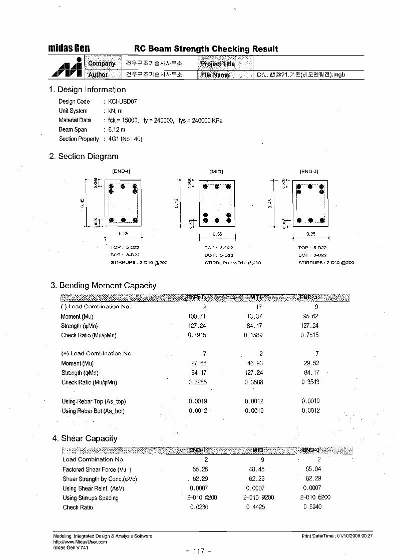
Section Property : 4G1 (No : 40)
e
AVWH
2. Section Diagram
[END-I]
Company
A ~ Y H O ~ ,
TOP : 5-D22 TOP : 3-D22
BOT : 3-D22 BOT : 5-D22
STIRRUPS : 2-Dl0 a200 STIRRUPS : 2-Dl0 @200
[END-J]
Z P 7 Z 7 1 Q A t A t P &
Z P 7 Z 7 1 Q A t A t P &
TOP: 5-D22
BOT : 3-D22
STIRRUPS : 2-Dl0 a200
3. Bending Moment Capacity
, X - *
-~rd;iek%~kle File Name
-- - --- . - > . - 7 - - J END-I = ' - ' MID , E N D 4 . 1
-- - --
D:\...E@?l.31Z(?192S e).rngb
(-) Load Combination No.
Moment (Mu)
Strength (qMn)
Check Ratio (MulqMn)
(+) Load Combination No.
Moment (Mu)
Strength (qMn)
Check Ratio (MulqMn)
Using Rebar Top (As-top) 0.0019 0.0012 0.0019
Using Rebar Bot (As-bot) 0.0012 0.0019 0.0012
4. Shear Capacity --
- END-I . -- MID END-J- - - - --
Load Combination No.
Factored Shear Force (Vu )
Shear Strength by Conc.(qVc)
Using Shear Reinf. (AsV)
Using Stirrups Spacing
Check Ratio
Modeling, Integrated Design &Analysis Software http://www.MidasUser.wm rnidas Gen V 741
- 117 -
Print DateTTime : 0111012009 00:27

niidas Gen RC Beam Strength Checking Result
1. Design Information Design Code : KCI-USD07
Unit System : kN, m Material Data : fck = 15000, fy = 240000, fys = 240000 KPa Beam Span : 6.4 m
Section Property : 4G2 (No : 41)
2. Section Diagram
[END-I]
TOP 8-D22 TOP. 3-D22
BOT 3-D22 BOT 8-D22
STIRRUPS , 2-Dl0 (9200 STIRRUPS 2-Dl0 a 2 0 0
[END-J]
TOP. 8-D22
BOT : 3-D22
STIRRUPS : 2-Dl0 a 2 0 0
3. Bending Moment Capacity ------,-- , . . .
-. . ' .EN.D-I ..... . - ............................. --A - . * MID . . ' :.END;J - 7
...............................
(-) Load Combination No.
Moment (Mu)
Strength (pMn)
Check Ratio (MulpMn)
(+) Load Combination No.
Moment (Mu)
Strength (pMn)
Check Ratio (MulpMn)
Using Rebar Top (As-top) 0.0031 0.0012 0.0031
Using Rebar Bot (As-bot) 0.0012 0.0031 0.0012
4. Sliear Capacity ... r---- -
- -- -- -
8 - .-1- L-- - -. .- - -. - END-I MID E.N D- J --- - - --- ......... .. ...................... . . .. .. .....
Load Combination No. 2 2 2
Factored Shear Force (Vu ) 116.18 94.29 116.13
Shear Strength by Conc.(pVc) 69.96 69.96 69.96
Using Shear Reinf. (AsV) 0.0007 0.0007 0.0007
Using Stirrups Spacing 2-Dl0 @200 2-010 @200 2-Dl0 @200
Check Ratio 0.9447 0.7667 0.9443
Modeling, Integrated Design &Analysis Sofhvare Print Datemime : 0111012009 00:27 http:llwww.MidasUser.com midas Gen V 741 - 118 -
midas Gen RC Beam Strength Checking Result
1. Design Information Design Code : KCI-USD07 Unit System : kN, m Material Data : fck = 15000, fy = 240000, fys = 240000 KPa
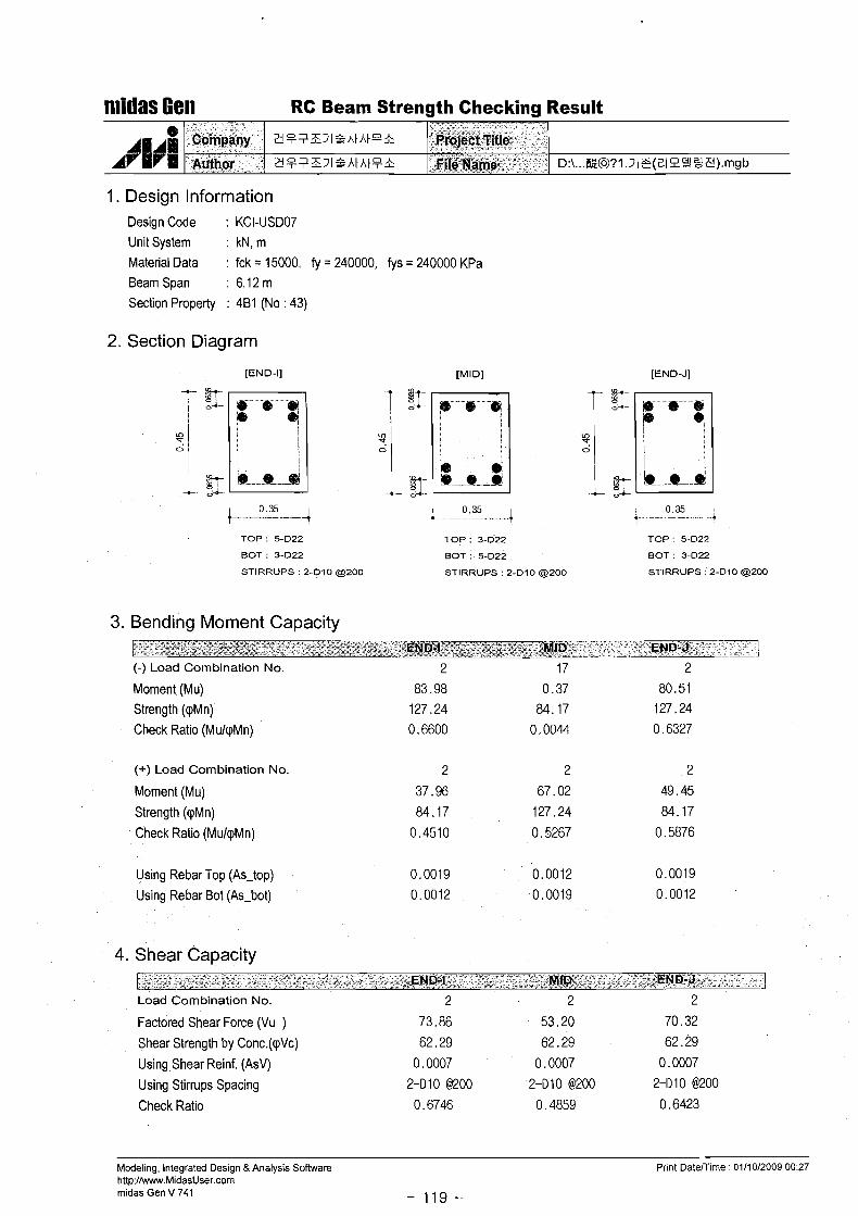
Beam Span : 6.1 2 m Section Property : 4B1 (No : 43)
2. Section Diagram
[END-I] [END-J]
TOP : 5-022 TOP : 3-D22 TOP : 5-022
BOT : 3-022 BOT : 5-D22 BOT : 3.022
STIRRUPS : 2-010 a 2 0 0 STIRRUPS : 2-Dl0 a 2 0 0 STIRRUPS : 2-010 a200
3. Bending Moment Capacity ----- " -- -- .- -- . . . . --- I,.,,: , . ( . . i.' . , .... , - END;~. :; .,.:. .;-;~.:-..r MID: . . END-J: , - .'I-
. . . . . . - . . . . . . .-._ -
(-) Load Combination No.
Moment (Mu) Strength (qMn)
Check Ratio (MulqMn)
(+) Load Combination No.
Moment (Mu)
Strength (qMn)
Check Ratio (MulqMn)
Using Rebar Top (As-top)
Using Rebar Bot (As-bot)
4. Shear Capacity --
fL-_- -- END-I " MID- END- J
Load Combination No. 2 2 2
Factored Shear Force (Vu ) 73.86 53.20 70.32
Shear Strength by Conc.(qVc) 62.29 62.29 62.29
Using Shear Reinf. (AsV) 0.0007 0.0007 0.0007
Using Stirrups Spacing 2-Dl0 @200 2-Dl0 64200 2-1110 @200
Check Ratio 0.6746 0.4859 0.6423
Modeling, Integrated Design &Analysis Software http:Ilwww.MidasUser.corn midas Gen V 741 - 119 -
Print Datenirne : 0111012009 00:27

midas 6en RC Beam Strength Checking Result
1. Design Information Design Code : KCI-USD07
Unit System : kN, m Material Data : fck = 15000, fy = 240000, fys = 240000 KPa Beam Span : 6.1 2 m
Section Property : 1 G I (No : 20)
2. Section Diagram
[END-I] [MIDI [END-J]
TOP : 5-D22 TOP : 3-D22 TOP : 5-D22
BOT : 3-D22 BOT . 5-D22 BOT : 3-D22
STIRRUPS : 2-Dl0 a 2 0 0 STIRRUPS ' 2-Dl0 a 2 0 0 STIRRUPS : 2-Dl0 a200
3. Bending Moment Capacity -- --
% , - EN94 .- , . MID E N D ~ --- I
(-) Load Combination No.
Moment (Mu)
Strength (cpMn)
Check Ratio (MulqMn)
(+) Load Combination No.
Moment (Mu)
Strength (qMn)
Check Ratio (MulcpMn)
Using Rebar Top (As-top)
Using Rebar Bot (As-bot)
4. Shear Capacity - - -
- END-I -- MID END-J -1 -.A -
Load Combination No. 2 2 2
Factored Shear Force (Vu ) 102.08 70.41 103.24
Shear Strength by Conc.(qVc) 62.29 62.29 62.29
Using Shear Reinf. (AsV) 0.0007 0.0007 0.0007
Using Stirrups Spacing 2-Dl0 @200 2-010 @200 2-010 @200
Check Ratio 0.9323 0.6431 0.9429
Modeling, Integrated Design & Analysis Soflware Print Datemime : 01/10/2009 00:32 http://www.MidasUser.com midas Gen V 741
- 120 -

n'ridas Gen RC Beam Strength Checking Result
1. Design Information Design Code : KCI-USD07
Unit System : kN, m
Material Data : fck = 15000, fy = 240000, fys = 240000 KPa Beam Span : 6.4 m
Section Property : 1G2 (No : 21)
2. Section Diagram
[END-I] [END-J]
TOP 8-D22 TOP : 3-D22 TOP ' 8-D22
BOT . 3-D22 BOT 8-D22 BOT 3-D22
STIRRUPS. 2-Dl0 (9200 STIRRUPS. 2-Dl0 (9200 STIRRUPS 2-Dl0 (9200
3. Bending Moment Capacity
(-) Load Combination No.
Moment (Mu)
Strength (pMn)
Check Ratio (MukpMn)
(+) Load Combination No.
Moment (Mu)
Strength (pMn)
Check Ratio (MukpMn)
Using Rebar Top (As-top)
Using Rebar Bot (As-bot)
4. Shear Capacity - . . END-I MID . END-J --
Load Combination No. 2 2
Factored Shear Force (Vu ) 111.96 89.37
Shear Strength by Conc.(pVc) 69.96 69.96
Using Shear Reinf. (AsV) 0.0007 0,0007
Using Stirrups Spacing 2-Dl0 @200 2-Dl0 @200
Check Ratio 0.9104 0.7267
Modeling, Integrated Design &Analysis Software
http:llwww.MidasUser.com midas Gen V 741
- 121 -
Print Datemime : 0111012009 00:35

midas Gen RC Beam Strength Checking Result
1. Design Information
- -
Design Code : KCI-USD07 Unit System : kN, m
Material Data : fck = 15000, fy = 240000, fys = 240000 KPa Beam Span : 6.4 m Section Property : 1 G3 (No : 22)
0 1111
A~~~~
2. Section Diagram
[END-J]
TOP : 8-D22 TOP : 3-D22 TOP : 8-D22
BOT . 3-D22 BOT : 8-D22 BOT : 3-D22
STIRRUPS : 2-Dl0 a200 STIRRUPS : 2-Dl0 a200 STIRRUPS : 2-Dl0 a200
Oompahy Author
3. Bending Moment Capacity
'-R~qj$pt Title . _ -- . "
%07 m e ' '
3 $ 7 Z 3 1 % h t h t F &
a p i Z 3 l $ h t h t ? &
(-) Load Combination No.
Moment (Mu) Strength (qMn)
Check Ratio (MulqMn)
D:\ ... awl . 3 I e ( 2 l e 2 3 y).mgb
(+) Load Combination No.
Moment (Mu)
Strength (qMn)
Check Ratio (MulqMn)
Using Rebar Top (As-top) Using Rebar Bot (As-bot)
. .
4. shear Capacity --- -
- - - - - - - - - - - - - - - - - - - - -- - - - - - - - END-1%
.. .MID END-J . -. - -- -
Load Combination No. 2 2 2
Factored Shear Force (Vu ) 243.32 194.11 241 .36
Shear Strength by Conc.(qVc) 69.96 69 .96 69.96
Using Shear Reinf. (AsV) 0.0007 0.0007 0.0007
Using Stirrups Spacing 2-010 @200 2-0 1 0 @200 2-010 @200
Check Ratio 1 ,9786 i ,5705 1 ,9627
Modeling, Integrated Design & Analysis Software http:llwww.MidasUser.com midas Gen V 741 - 122 -
Print Datemime : 0111012009 00:36

midas Gen RC Beam Strength Checking Result
1. Design Information Design Code : KCI-USD07 Unit System : kN, m Material Data : fck = 15000, fy = 240000, fys = 240000 KPa Beam Span : 6.1 2 m Section Property : 1 B2 (No : 25)
A 1 1 1 . . A r I m I-Auth~r
I I Z P 7 Z J l Q h t h t P h 1 File Name
2. Section Diagram
D:\ ... @@71 7 z (Uen5Y) .mgb
[END-I] [MI Dl
TOP : 5-022 TOP : 3-022
BOT : 3-D22 BOT : 5-D22
STIRRUPS : 2-Dl0 @200 STIRRUPS : 2.010 @ZOO
[END-J]
TOP : 5-022
BOT : 3-D22
STIRRUPS : 2-Dl0 a200
3. Bending Moment Capacity . . . . - - - - .? - . . . - -- . . . - . . - - - - - - - . -. .- --
END-I .. . -. MID END-J . .- -- -- -- ... . .... . .
(-) Load Combination No.
Moment (Mu) Strength (cpMn) Check Ratio (MuIcpMn)
(+) Load Combination No
Moment (Mu) Strength (cpMn)
Check Ratio (MuIcpMn)
Using Rebar Top (As-top) Using Rebar Bot (As-bot)
4. Shear Capacity
Load Combination No.
Factored Shear Force (Vu )
Shear Strength by Conc.(cpVc)
Using Shear Reinf. (AsV)
Using Stirrups Spacing
Check Ratio
Modeling, Integrated Design &Analysis Sofhvare Print Datemime : 0111012009 00:41 http:llwww.MidasUser.com midas Gen V 741 - 123 -

rrlidas Gen RC Beam Strength Checking Result
4 . Design Information Design Code : KCI-USD07
Unit System : kN, m Material Data : fck = 15000, fy = 240000, fys = 240000 KPa BeamSpan : 6 . 1 2 m '
Section Property : 'I B1 (No : 24)
- -
2. Section Diagram
AHAN AVHrW
[END-I] [MIDI [END-J]
TOP : 5-D22 TOP ' 3-D22 TOP : 5-D22
BOT : 3-D22 BOT : 5-D22 BOT : 3-D22
STIRRUPS : 2-Dl0 (9200 STIRRUPS : 2-Dl0 a 2 0 0 STIRRUPS 2-Dl0 (9200
-G-Omp%any
author
3. Bending Moment Capacity r-- . - - -- -- - -- -- -- - -- ENDtl' ._
--- -- MID -- END-J 1 -
(-) Load Combination No.
Moment (Mu)
Strength (qMn)
Check Ratio (MulqMn)
D:\ ... E ~ ? I . J I T ( Z I P ~ ~ F ) . ~ ~ ~
2187ZJ IQAtA tP&
~ F ~ Z J I ~ A I A ~ P &
(+) Load Combination No.
Moment (Mu)
Strength (qMn)
Check Ratio (MulqMn)
Pr~Iect Title
~ i l e '&me
Using Rebar Top (As-top)
Using Rebar Bot (As-bot)
4. Shear Capacity
r END-I MID -. END-J Load Combination No. 2 10 2
Factored Shear Force (Vu ) 68.62 56.60 69.29
Shear Strength by Conc.(cpVc) 62.29 65.49 62.29
Using Shear Reinf. (AsV) 0.0007 0.0007 0.0007
Using Stirrups Spacing 2-Dl0 @200 2-Dl0 @200 2-Dl0 @200
Check Ratio 0.6267 0.4917 0.6328
Modeling, Integrated Design & Analysis Software http:llwww.MidasUser.com midas Gen V 741 - 124 -
Print Datemime : 01/1012009 00:40
m~idas Gem RC Beam Strength Checking Result
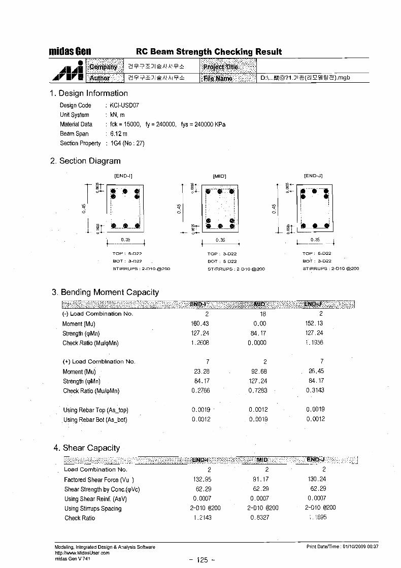
1. Design Information Design Code : KCI-USD07 Unit System : kN, m Material Data : fck = 15000, fy = 240000, fys = 240000 KPa Beam Span : 6.1 2 m Section Property : 1 G4 (No : 27)
2. Section Diagram
[END-I] [MIDI [END-J]
TOP : 5-D22 TOP : 3-D22 TOP : 5-D22
BOT : 3-D22 BOT : 5-D22 BOT : 3-D22
STIRRUPS : 2-Dl0 a 2 0 0 STIRRUPS : 2-Dl0 @200 STIRRUPS : 2-Dl0 a200
3. Bending Moment Capacity
(-) Load Combination No.
Moment (Mu)
Strength (pMn) Check Ratio (MulpMn)
(+) Load Combination No
Moment (Mu) Strength (pMn) Check Ratio (MulpMn)
Using Rebar Top (As-top)
Using Rebar Bot (As-bot)
4. Shear Capacity - . -- - -
END-I MID END-J I
.- - - -
Load Combination No. 2 2 2
Factored Shear Force (Vu ) 132.95 91.17 130.24
Shear Strength by Conc.(cpVc) 62.29 62.29 62.29
Using Shear Reinf. (AsV) 0.0007 0.0007 0.0007
Using Stirrups Spacing 2-Dl0 8200 2-Dl0 @200 2-010 8200
Check Ratio 1 . ? I 4 3 0.8327 1.1895
Modeling, Integrated Design & Analys~s Software Print Datemime : 0111012009 00:37 hltp:llwww.MidasUser.com midas Gen V 741 - 125 -

midas Gen RC Beam Strength Checking Result
1. Design Information
-
Design Code : KCI-USD07 Unit System : kN, m Material Data : fck = 15000, fy = 240000, fys = 240000 KPa Beam Span : 6.12 m Section Property : 103 (No : 26)
AVMrl
2. Section Diagram
[END-I] [MIDI
Company
Author
TOP : 5-D22 TOP : 3-D22
BOT : 3-D22 BOT : 5-D22
STIRRUPS : 2-Dl0 a200 STIRRUPS : 2-Dl0 a200
[END-J]
TOP : 5-D22
BOT : 3-D22
STIRRUPS : 2-Dl0 a200
D:\ ... EQ? I .~ IT (~ IPZ~ ~ ) . m g b
Y,F7&2lQhthtF&
Z F ~ & ~ I ~ A I A I F &
3. Bending Moment Capacity
.Proje'ct Title
'.~iie Name
----- Ll-7Z- .- -- - *ND-I -' -- MID . - ..L END.J-- 1 (-) Load Combination No.
Moment (Mu)
Strength (pMn)
Check Ratio (MulpMn)
(+) Load Combination No.
Moment (Mu) Strength (pMn)
Check Ratio (MulpMn)
Using Rebar Top (As-top)
Using Rebar Bot (As-bot)
4. Shear Capacity r-- -- -. . - - . - - -- - . - -- I
-- -. .- - .- - -- END-1 MID
Load Combination No.
Factored Shear Force (Vu )
Shear Strength by Conc.(pVc)
Using Shear Reinf. (AsV)
Using Stirrups Spacing
Check Ratio
Modeling, Integrated Design &Analysis Software http://www.MidasUser.wm midas Gen V 741 - 126 -
Print Datemime : 01/10/2009 00:42

1. Geometry and Materials
midas Set Beam Strengthening [8G3(Xt S S ) ]
Design Code : KCI-USDO3 (Build.)
Stress Profile : Parabolic
Material Data : fck = 15 MPa ( P 1 = 0.850)
AICl
f, = 240, fYs = 240 MPa
Section : 500 * 350 mm (hf=120, bf=1600 mm) PY
Top Bar (Layer 1) : 4 - D22 (dr = 60 mm)
Bot. Bar (Layer I ) : 4 - D22 (de = 60 mm) Bot. Bar (Layer 2) : 4 - D22 (de = 110 mm)
Stirrups : 2 - D 1 0 @ 2 0 0
2. Strengthening Materials
.:cawm/ -- - Jt) tk~g_$&~~,~ee~aemmn
Location Wsn(mm) Tsu(mm) fsdMPa) EdMPa) Reduc.F( B
3. Member Force and Moment -.Mu = 330.0kN-m Vu = 100.0kN
kUnwm
4. Check Tension Reinforcement -. AS = Z(Abar+k~~*(fst~/fv)* P ) = 6037 mm2
-. AS' = Z(Abar'+k~~'*(fs~/fy)* P ) = 1548 mmZ
-. dc = (As*ZdcO/(As) = 44mm
-. dc' = (Asi*Zdcc)/(As') = 6 0 m m
-. d = H-dc = 456 mm
* > -" > , 7
[ ~ , 6 j & t ~ $ ~ m ~ ~ ~ ~ --r .mq2 l
,
. * .- tiiej&;me '-" p < s* +
-. ~b = 0.85 P 1(f'c/fy)*600/(600+f,) = 0.0323
-. fsb' = 600 - dc'/d'*(600+f,) = 485.5 MPa
-. fsb = Min[fsbl, fyl = 240.0 MPa
-. A,,, = 0.75pu(H-dc)B+A,'*fsI:/fY = 19213 > 6037 mm2 . . . . . . . 0. K.
5. Bending Moment Capacity - Before Strengthening -. Neutral Axis Depth c = 53 mm
-. Compression : Concrete Cc = 872.0 kN
-. Compression : Rebar C, = 0 .0kN
-. Tension : Rebar Ts = -873.8 kN
-. Strength Reduction Factor 0 = 0.850
-. Design Moment Strength 0 Mn= 252.5 kN-m , $.;;:Y..<;;+r: L<z;.(; . c;; !$, :: 1 , 2:;! ;, 1 ,<y;:; , , , . ,5;;: s:-;,,:;!!.
midas Set V 3.3.4 http:llwww.MidasUser.com
Date : 0111012009 - 1 1 2 -

midas Set Beam Strengthening [8G3(XtZ &!)I
6. Bending Moment Capacity - After Strengthening -. Neutral Axis Depth c = 74 mm
- - -
-. Compression : Concrete Cc = 1284.5 kN
-. Compression : Rebar Cs = 164.3 kN
-. Tension : Rebar Ts = -743.2 kN
-. Tension : Steel PL T~II = -705.6 kN
'"; Company hnwoo
-. Strength Reduction Factor @ = 0.850
-. Design Moment Strength @M,= 518.4 kN-m
-. Strength Ratio : M,/OM- = 0.637 < 1.000 . . . . . . . 0 . K
%cojec'i flanie
F'illq Wme
7. Check Shear -. Strength Reduction Factor O = 0.750
-. V, = 1/6&Bd = 93.8kN
-. Vs = Avfyd/s = 71.0 kN
-. OVn= O(V,,+Ve) = 123.6 kN > V, = 100.0 kN ---> O.K.
midas Set V 3.3.4 http:l/www.MidasUser.com
Date : 0111 012009 - 2 1 2 -

n'ridas Set Beam Strengthening [8G5(XtZ 2 )]
I. Geometry and Materials t- 1400 -+ Design Code : KCI-US003 (Build.)
Stress Profile : Parabolic
Mater~al Data : fck = 15 MPa ( B i = 0.850)
fy = 240, fys = 240 MPa 1 350 1 +--? Section : 450 * 350 mm (hf=120, bf=1400 mm)
Top Bar (Layer 1 f : 2 - 022 (dr = 60 mm) Bot. Bar (Layer 1) : 3 - 022 (de = 60 mm)
Bot. Bar (Layer 2) ' 2 - 022 (de = 110 mm)
Stirrups : 2 - 0 1 0 @ 2 0 0
- - - . -
2. Strengthening Materials Location Wstl(rnm) Tstl(mm1 fsu(MPa) Es,l(MPa) Reduc.F{ B 1
1 350 6 240 210000 0.7
llli ArBl'm
3. Member Force and Moment
4. Check Tension Reinforcement
Company
Qeesig.nery
-. & = E(Abar+&l~*(fst~/fy)* 0 ) = 4180 mm2
-. As' = E(Abarl+&tl'*(fss/fyb 0 ) = 0 mm2
-.dc = (As*Edc~)/(As) = 109 mm
-. dc' = (As'*Edcc)/(As') - - 0 mm
-. d = H-dc = 341 mm
-. Asm,n~ = (0.2.5&Ify)*Bd = 481 mm2
-. As.mlnn = (1 .4/fy)*Bd = 696 mm2
-. Asrq = Max [A:,,,I. A:mlriI = 696 < 4180 mm' . . . . . . . 0 . K
lunwoo
lee ~aernmn
-. p b = 0.85 B,(f'clfy)*600/(600+fy) = 0.0323
-. fsb' = 600 - dC'/d1*(600+fy) = 600.0 MPa
-. fsb = Min[fsbl, f y l = 240.0 MPa
-. AS-a = 0.75pAH-ds)B+As'*fs~/fy = 11539 > 4180 mm2 . . . . . . O.K.
Project Name
Fii*i't$amesAiL ** &-
5. Bending Moment Capacity - Before Strengthening -. Neutral Axis Depth c = 42 mm
-. Compression : Concrete Cc = 650.3 kN
-. Compression : Rebar Cs = 0.0 kN
-. Tension : Rebar Ts = -650.3 kN
-. Strength Reduction Factor 0 = 0.850
-. Des~gn Moment Strength 0Mn= 145.1 kN-m , - * , . * & L a
> , % Y - I . > < ? ' > I , , , ' * - , >. , ' \,
midas Set V 3.3.4 http:llwww.MidasUser.com
Date : 0111012009 - 1 1 2 -
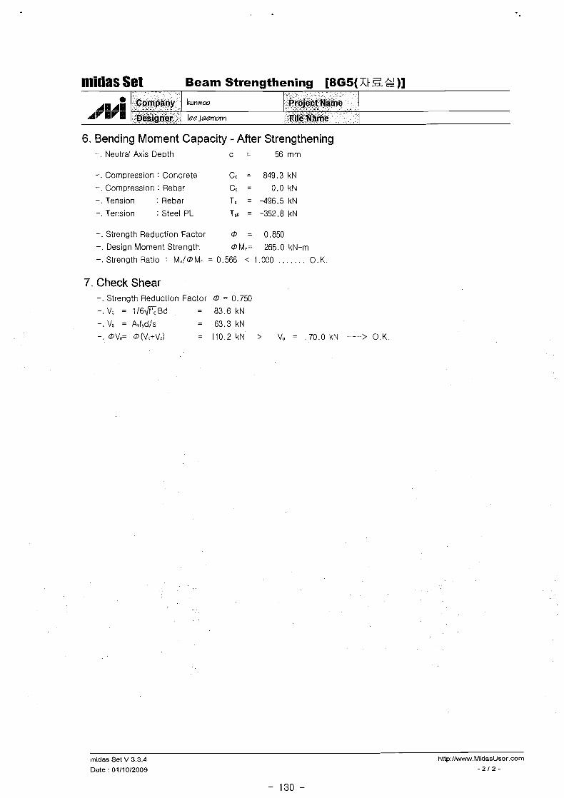
n'lidas Set Beam Strengthening [8G5(Xt iZ &+!)I
6. Bending Moment Capacity - After Strengthening -. Neutral Axis Depth c = 56 mm
-. Compression : Concrete C, = 849.3 kN
-. Compression : Rebar Cs = 0 .0kN
-. Tension : Rebar Ts = -496.5 kN
-. Tension : Steel PL TSu = -352.8 kN
-. Strength Reduction Factor 0 = 0.850
-. Design Moment Strength OMn= 265.0 kN-m
-. Strength Ratio : M.,/OM- = 0.566 < 1.000 . . . . . . . O.K.
7. Check Shear -. Strength Reduction Factor 0 = 0.750
-. V, = 1/6flBd = 83.6 kN
-. Vs = Avfydls = 63.3kN
-. @Vn= 0 (Vl+V<) = 110.2 kN > V , = 70.0 kN ---> 0 .K
midas Set V 3.3.4
Date : 0111 012009
1. Geometry and Materials i 1400 ~ - . 4
Design Code : KCI-USDO3 (Build.) . C'T Stress Profile : Parabolic 5? 1
9 i Material Data : fck = 15 MPa ( P I = 0.850) 1 .:-..:
f, = 240, fYs = 240 MPa 350 (- Section : 450 * 350 mm (hf=120, bf=1400 mm)
Top Bar (Layer 1) : 2 - 022 (dr = 60 mm)
Bot. Bar (Layer 1 ) : 3 - D22 (de = 60 mm)
Bot. Bar (Layer 2) : 2 - 022 ( d ~ = 110 mm)
Stirrups : 2 - D 1 0 @ 2 0 0
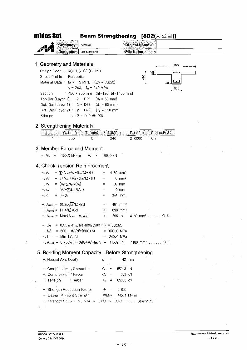
mridas Set Beam Strengthening [8B2(7;t S 2)]
2. Strengtherring Materials
A W ~
Location Wru(mm) Tsu(mm) fsdMPa) E,,I(MP~) Reduc.F( P
3. Member Force and Moment -. Mu = 160.0 kN-m Vu = 80.0 kN
$ 6 p E a ~ -- ;&_signer - -
4. Check Tension Reinforcement -. As = z(Abar+&~~*(fst~/fy)* P I = 4180 mm2
-. As' = z(Abarl+&tl'*(fs~l/fy)* P ) = 0 mm2
-. dc = (As*zdct)/(As) = 109 mm
-. dc' = (As'*zdcc)/(Asl) - - 0 mm
-. d = H-dc = 341 mm
-. As.min~ = (0.25$Z/fy)*Bd = 481mm2
-. As.mi~ = (1 .4/fq)*Bd = 696 mm2
-. At,;, = Max [A;.miri. A-.mir-21 = 696 < 4180mm2 . . . . . . . O.K.
bnwoo
tajaammn
-. p b = 0.85 P1(f '~ l fy)*600/(600+f~) = 0.0323
-. fsb' = 600 - dc'/d'*(600+fy) = 600.0 MPa
-. fsb = Min[fsbl, f y l = 240.0 MPa
- . A,-a = 0.75p3(H-dC)B+As'*fso/fy = 11539 > 4180 mmP . . . . . . O.K.
, - * - hpj<=tt$lt(arnb - - - '" ~iik~&ie" ' :i"-
5. Bending Moment Capacity - Before Strengthening -. Neutral Axis Depth c = 42 mm
-. Compression : Concrete Cc = 650.3 kN
-. Compression : Rebar Cs = 0 .0kN
-. Tens~on : Rebar Ts = -650.3 kN
-. Strength Reduction Factor 0 = 0.850
-. Design Moment Strength 0 Mn= 145.1 kN-m <:<.??~ .-.,,T 1; ;;<,:.,; :_,:: l.: :. . . . . *..i 1 , I.?:? :. 1,:)2: , , , , . . . 8~ieng;'-,
rnidas Set V 3.3.4
Date : OiIi012009

midas Set Beam Strengthening [8B2(XtZ &!)I
6. Bending Moment Capacity - After Strengthening -. Neutral Axis Depth c = 56 mm
t lA; A
-. Compression : Concrete Cc = 849.3 kN
-. Compression : Rebar Cs = 0 .0kN
-. Tension : Rebar Ts = -496.5 kN
-. Tension : Steel PL T~II = -352.8 kN
-. Strength Reduction Factor 0 = 0.850
-. Design Moment Strength 0 Mn= 265.0 kN-m
-. Strength Ratio : Mii/OM, = 0.604 < 1.000 . . . . . . . 0. K .
Company
Designer
7. Check Shear -. Strength Reduction Factor 0 = 0.750
-. Vc = 1/6flBd = 83.6kN
-. Vs = AvfYd/s = 63.3 kN
-. 0Vn= 0 (V:;+VJ = 110.2 kN > Vo = 80.0 kN ---> O.K.
midas Set V 3.3.4 http:llwww.MidasUser.com
Lnwm
lee~aernmn
Date : 0111 012009 - 2 12 -
Groje~t Name
' kilt$?ame '

1. Geometry and Materials
midas Set Beam Strengthening [I G3(+ 2 gt)]
Design Code : KCI-US003 (Build.)
Stress Profile : Parabolic
Material Data : fck = 15 MPa ( P I = 0.850)
"" /HA1
Hlrl
f, = 240, fYs = 240 MPa
Section : 500 * 350 mm (hf=120, bf=1600 mm)
Top Bar (Layer 1) : 4 - 022 (dr = 60 mm)
Bot. Bar (Layer I ) : 4 - 022 (de = 60 mm)
Bot. Bar (Layer 2) : 4 - 022 (ds = 110 mm)
Stirrups : 2 - D 1 0 @ 2 0 0
2. Strengthening Materials
~ o r n ~ ~ C i y 0eSigner
3. Member Force and Moment -. Mu = 350.0 kN-m Vu = 100.0 kN
4. Check Tension Reinforcement -. As = x(Abar+Astl*(fsl\/fy)* ) = 6037 mm2
-. As' = x(Aba,'+Asu1*(fsalfv)* P ) = 1548 mm2
-. dc = (As*zdc~)/(As) = 44 mm
-. dc' = (As'*Zdcc)/(As') = 6 0 m m
-. d = H-dc = 456 mm
k~lnwoo
lee ~aemonn
-. Asmln~ = (0 .2G/ f y ) *Bd = 644 mm2
-. Asm(n2 = (1 .4/fy)*Bd = 932 mm2
-. As-, = Max[A;mlrl. Asrnlril = 932 < 6037 mm' . . . . . . O.K.
- " - - "
~ r o j e d f ~ a h e ." ",
E,ile Name
-. p b = 0.85 P l(f'c/fy)*600/(6O0+fy) = 0.0323 -. f s i = 600 - dc1/d'*(600+fy) = 485.5 MPa
-. fsb = Min[fsbl, fyl = 240.0 MPa
- A, , = 0.75p91H-dC)B+As1*fso/f, = 19213 > 6037 mm2 . . . . . . . 0 . K.
5. Bending Moment Capacity - Before Strengthening -. Neutral Axis Depth c = 53 mm
-. Compression : Concrete Cc = 872.0 kN
-. Compression : Rebar Cs = 0 . 0 k N
-. Tension : Rebar Ts = -873.8 kN
-. Strength Reduction Factor @ = 0.850
-. Design Moment Strength @ Mn= 252.5 kN-m .. . <;;:c:-: ,7+$> . ;., < > . kZ.l:..\ . . -A\:i; . . :;1:</ ~ ' (:? g;, : 1 , 2.56 ;, . 5CY! ,... ; , , . , , . . S;; ::-l:gl::
midas Set V 3.3.4 http://w.MidasUser.com
Date : 01/1012009 - 1 1 2 -

midas Set Beam Strengthening [I G3(& 2 g)]
6. Bending Moment Capacity - After Strengthening -. Neutral Axis Depth c = 74 rnrn
-. Compression : Concrete Cc = 1284.5 kN
-. Compression : Rebar Cs = 164.3 kN
-. Tension : Rebar Ts = -743.2 kN
-. Tension : Steel PL Tst~ = -705.6 kN
-. Strength Reduction Factor @ = 0.850 -. Design Moment Strength @Mn= 518.4 kN-rn
-. Strength Ratio : MJ@M- = 0.675 < 1.000 . . . . . . . O.K.
7. Check Shear -. Strength Reduction Factor @ = 0.750
-. Vc = 1 /6f lBd = 93.8 kN
-. Vs = Avfydls = 71.0 kN
-. @ Vn= @ (Vc+VJ = 123.6 kN > V, = 100.0 kN ---> O.K.
midas Set V 3.3.4 http:llwww.MidasUser.com
Date : 0111 012009 - 2 1 2 -
1. Geometry and Materials -i 1" . 4
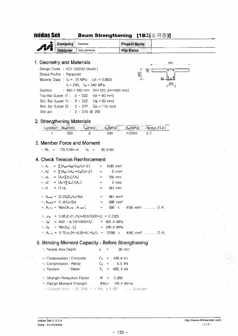
midas Set Beam Strengthening [I B2(& % 3-)]
Design Code : KCI-USDO3 (Build.)
Stress Profile : Parabolic
Material Data : fck = 15 MPa ( P I = 0.850)
f, = 240, fys = 240 MPa i 350 1 ---t Section : 450 * 350 mm (hf=120, bf=1600 mm)
Top Bar (Layer 1) : 2 - 022 (dr = 60 mm)
Bot. Bar (Layer 1) : 3 - D22 (de = 60 mm)
Bot. Bar (Layer 2) : 2 - 022 (de = 1 1 0 mm)
Stirrups : 2 - D 1 0 @ 2 0 0
A A;
2. Strengthening Materials
C~mpany b n w m
-
Location Wg(mm) Tss(mrn) fsdMPa) Esa(Mpa) Reduc.F( P
' Projedf @asme
-$i&zlwlacmanAA .Rile. Name
3. Member Force and Moment -. Mu = 170.0 kN-m Vu = 90.0 kN
4. Check Tension Reinforcement - = x(Abar+&l~*(fst~/fy)* 13) = 4180 mm2
-. As' = x(Abar1+&t~'*(fstl/fy)* P ) = 0 mm2
-. dc = (As*xdc~)/(As) = 109 mm
-. dc' = (As'*xdcc)/(Asl) - - 0 mm
-. d = H-dc = 341 mm
-. As.min~ = (0.25&/fy)*Bd = 481 mm2
-. As.min2 = (1.4/fy)*Bd = 696mm2
-. Axrn = Ma~[A;mirl. Asrnir~l = 696 < 4180 m m L .. . . . . . O.K.
-. p b = 0.85 P 1(f'~lfy)*600/(600+fv) = 0.0323
-. fSb1 = 600 - dc'/d'*(600+fy) = 600.0 MPa
-. fsb = Min[fsbl, f,] = 240.0 MPa
- . A, = 0.75p1(H-d0B+As1*fso/fy = 13188 > 4180 mm2 . . . . . . O.K.
5. Bending Moment Capacity - Before Strengthening -. Neutral Axis Depth c = 39 mm
-. Compression : Concrete CC = 649.4 kN
-. Compression : Rebar Cs = 0 .0kN
-. Tension : Rebar Ts = -650.3 kN . .
-. Strength Reduction Factor 0 = 0.850
-. Design Moment Strength OM,= 146.4 kN-m . , , .. .,. ,, ,,-? ?.i. .- .I. .;:.: I ;, 1 , ;>>;; , , , , , , ,!< ;; <>>.k!>l, ; ,! . : v . . . , ,
midas Set V 3.3.4
Date : 0111 012009
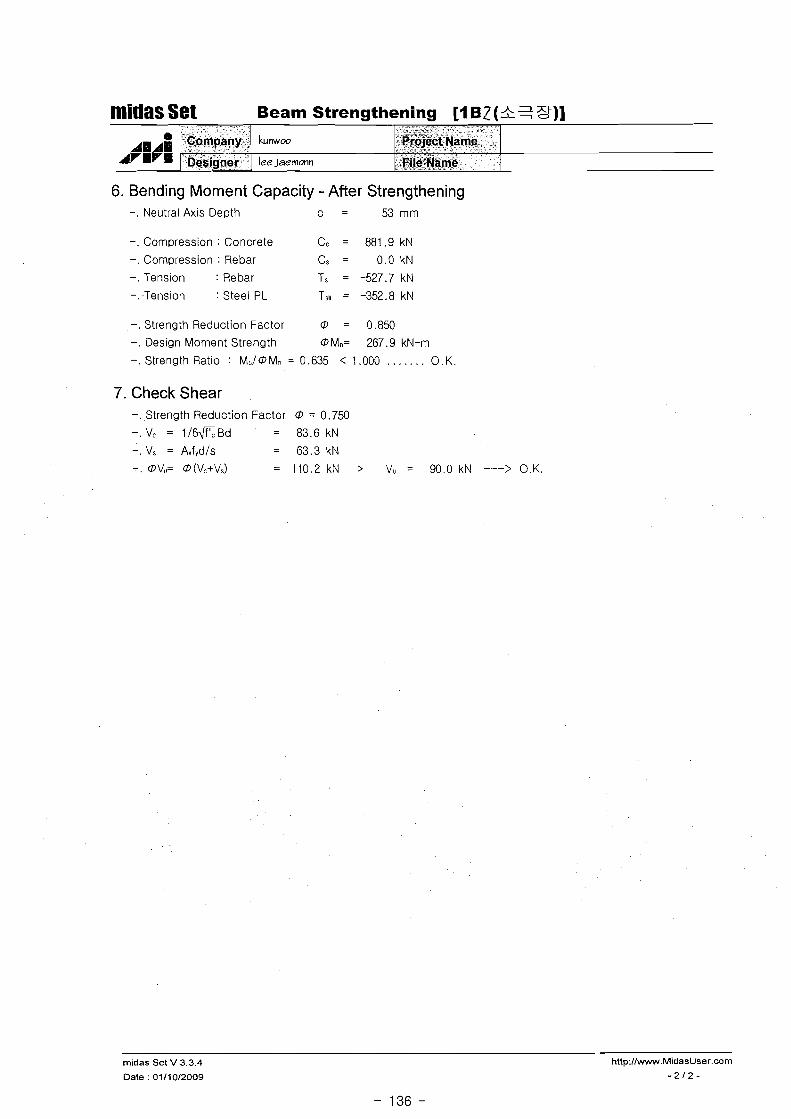
-. Compression : Concrete Cc = 881.9 kN
-. Compression : Rebar Cs = 0 . 0 k N
-. Tension : Rebar Ts = -527.7 kN
-. Tension : Steel PL T~II = -352.8 kN
midas Set Beam Strengthening [I B2 (& 2 St)]
-. Strength Reduction Factor 0 = 0.850
-. Design Moment Strength OMn= 267.9 kN-m
-. Strength Ratio : M,/OM, = 0.635 < 1.000 . . . . . . . 0 . K
I, lvI
7. Check Shear -..Strength Reduction Factor O = 0.750 -. Vc = 1/6fiBd = 83.6kN
-. Vs = Avfydls = 63.3 kN - . 0 V,,= 0 (Vc+Vs) = 110.2kN > V,, = 90 .0kN - - ->O.K.
midas Set V 3.3.4
Date : 0111012009
6. Bending Moment Capacity - After Strengthening -. Neutral AXIS Depth c = 53 mm
- Company
Desig"er
Lnwm
lee~aemmn
~, k *(
." ($$8$$ic'€~arne - s
:Iki,~&eqame

midas Set Beam Strengthening [I G4(Z 91 3 )]
1. Geometry and Materials 1600 1 -- - -
4
Deslgn Code : KCI-USD03 (Build.)
Stress Profile : Parabolic 3 Material Data : fck = 15 MPa ( 13 I = 0.850) 01 "T
fy = 240, fvs = 240 MPa e!!q Section : 450 * 350 mm (hf=120, bf=1600 mm) Top Bar (Layer 1) : 2 - 022 ( d ~ = 60 mm)
Bot. Bar (Layer 1 ) : 3 - 022 ( d ~ = 60 mm) Bot. Bar (Layer 2) : 2 - 022 (de = 110 mm)
St i r ru~s : 2 - D l0 @ 200
~ v ~ P ~
2. Strengthening Materials Location Wstllmm) T,s(rnm) fsn(MPa) Ess(MPa) Reduc.F( P
1 350 6 2 40 210000 0.7
3. Member Force and Moment
Company
Designer
4. Check Tension Reinforcement -. As = x(Abar+Astt*(fstl/fy)* 13) = 4180 mm2
. A = x(Abar'+Asul*(fstl/fy)* 13 ) = 0 mm2 -. dc = (As*Xdct)/(As) = 109 mm
-. dc' = (As1*tdcc)/(As') - - 0 mm
-. d = H-dc = 341 mm
-. ,ob = 0.85 131(f'c/fy)*600/(600+f~) = 0.0323
-. fsbl = 600 - dc'/d1*(600+fY) = 600.0 MPa
-. fsb = Min[fsbl, f y l = 240.0 MPa
- A,-s = G.75pl(H-d,)B+As'*f~L/fy = 13188 > 4180 mm? . . . . . . O.K.
Lvmw
lee ~aemonn
5. Bending Moment Capacity - Before Strengthening -. Neutral Axis Depth c = 39 mm
-. Compression : Concrete Cc = 649.4 kN
-. Compression : Rebar Cs = 0 . 0 k N
-. Tension : Rebar Ts = -650.3 kN
Project Name
File Name
-. Strength Reduction Factor 0 = 0.850
-. Design Moment Strength OM,= 146.4 kN-m ,. :,. .....: . ,:, :. :;: .:,: < ; . %?;< ::; . ?.$ ; <;> y. :- 1 , $;>Jc ;, ; , V,', .\ .: . . .
midas Set V 3.3.4 http:Ilwww.MidasUser.com
Date : 0111 012009 - 1 1 2 -

6. Bending Moment Capacity - After Strengthening -. Neutral Axis Depth c = 53 mm
midas Set Beam Strengthening [I G4(% 91 3 )]
-. Compression : Concrete Cc = 881.9 kN
-. Compression : Rebar Cs = 0 . 0 k N
-. Tension : Rebar Ts = -527.7 kN
-. Tension : Steel PL T~II = -352.8 kN
A l A E A v I v l
-. Strength Reduction Factor 0 = 0.850
-. Design Moment Strength OMn= 267.9 kN-m
-. Strength Ratio : M,/OMq = 0.560 < 1.000 . . . . . . . O.K.
7. Check Shear -. Strength Reduction Factor 0 = 0.750
-. Vc = 1 / 6 G B d = 83.6kN
-. Vs = Avfydls = 63.3 kN
-. 0V,,= 0 (VL+?/:) = 110.2 kN > V, = 70.0 kN ---> O.K.
Company
- Ddsigne;
midas Set V 3.3.4
Date : 01/10/2009
bnwoo
lee ~aernmn
, . , ~r~$er;t&ame
*
ti~etfiatij-k,

1. Geometry and Materials ( . -. - - - 1600 .-. -A
rnidas Set Beam Strengthening [I B3(S el 3 Y )]
Design Code : KCI-USD03 (Bulld.1 -7 0
Stress Profile : Parabolic UI: v Material Data : fck = 15 MPa ( P I = 0.850) -L
fy = 240, fys = 240 MPa t-....i 350 ,
Section : 450 * 350 mm (hf=120, bf=1600 mm) Top Bar (Layer 1) : 2 - 022 (dr = 60 mm)
Bot. Bar (Layer 1 ) : 3 - 022 (ds = 60 mm)
Bot. Bar (Layer 2) : 2 - 022 (ds = 110 mm)
Stirruos : 2 - D 1 0 @ 2 0 0
2. Strengthening Materials
(I,
AHAH AVlrm
Location Wsu(rnm) TSlt(rnrn) fsr(MPa1 Esn(MPa)-- Reduc.F( P )
Company
0e$jgi4r
kunwoo
lee ~aemonn
3. Member Force and Moment -. M, = 160.0 kN-m V, = 80.0 kl\l
- -- Projetit Name
. EiL?l4arne
4. Check Tension Reinforcement -. As = E(Abar+ke*(fst~/fy)* P ) = 4180 mm2
-. As' = E(Abar'+kt~'*(fsu/fy)* P ) = 0 mm2
-. dc = (As*Edct)/(As) = 109 mm
-. dc' = (As'*Edcc)/(As') - - 0 mm
-. d = H-dc = 341 mm
-. Asmlnt = (0.2!&/fy)*Bd = 481 mm2
-. As.mrn~= (1 .4/fy)*Bd = 696mm2
-. A,,, = Max [&mlr~. As m~rrI = 696 < 4180 mm' . . . . . . . O.K.
-. ~b = 0.85 0 ~(f1c/fy)*600/(600+fy) = 0.0323
-. fsb' = 600 - dc'/d'*(600+fy) = 600.0 MPa
-. fsb = Mitl[fsbq, fy] = 240.0 MPa
-. A%.., = 0.75p3(H-dC)B+As1*f,,/f, = 13188 > 4180 mm? . . . . . . O.K.
5. Bending Moment Capacity - Before Strengthening -. Neutral Axis Depth c = 39 mm
-. Compression : Concrete Cc = 649.4 kN
-. Compression : Rebar Cs = 0.0 kN
-. Tension : Rebar Ts = -650.3 kN
-. Strength Reduction Factor @ = 0.850
-. Design Moment Strength @Mn= 146.4 kN-m C?.:::.,<:+.; ;.;?!I;;> : ?+l:,;(>:,?: -: [,c)L::l, ;> i,:j;:<j , , , , .
, - 8 . . .. .. .
midas Set V 3.3.4
Date : 0111012009

midas Set Beam Strengthening [I B3(% el f )]
6. Bending IWoment Capacity - After Strengthening -. Neutral Axis D e ~ t h c = 53 rnrn
- - -
-. Corn~ression : Concrete Cc = 881.9 kN
-. Corn~ression : Rebar Cs = 0.0 kl\J
-. Tension : Rebar Ts = -527.7 kN
-. Tension : Steel PL Tnl = -352.8 kN
A 1 e i 1
-. Strength Reduction Factor @ = 0.850
-. Design Moment Strength @M,= 267.9 kN-rn
-. Strength Ratio : M,/@M, = 0.597 < 1.000 . . . . . . . 9. K.
7. Check Shear -. Strength Reduction Factor 0 = 0.750
-. Vc = 1 / 6 G B d = 83.6kN
-. Vs = AvfYd/s = 63.3kN
-. @V,,= @ (Vc+V,) = 110.2 kN > V, = 80.0 kN ---> O.K.
.: m:
,C~gpf$v'> z%eGijjirer $ + A :
midas Set V 3.3.4 http://www.MidasUser.com
Date : 01110/2009 - 2 1 2 -
- 140 -
b n w w
lee ~aernmn
. - .Wu- . -*-". A- V' " - * j $ 6 ~ ~ ~ ~ $ ~ ~ ;-
Ti!g@arne
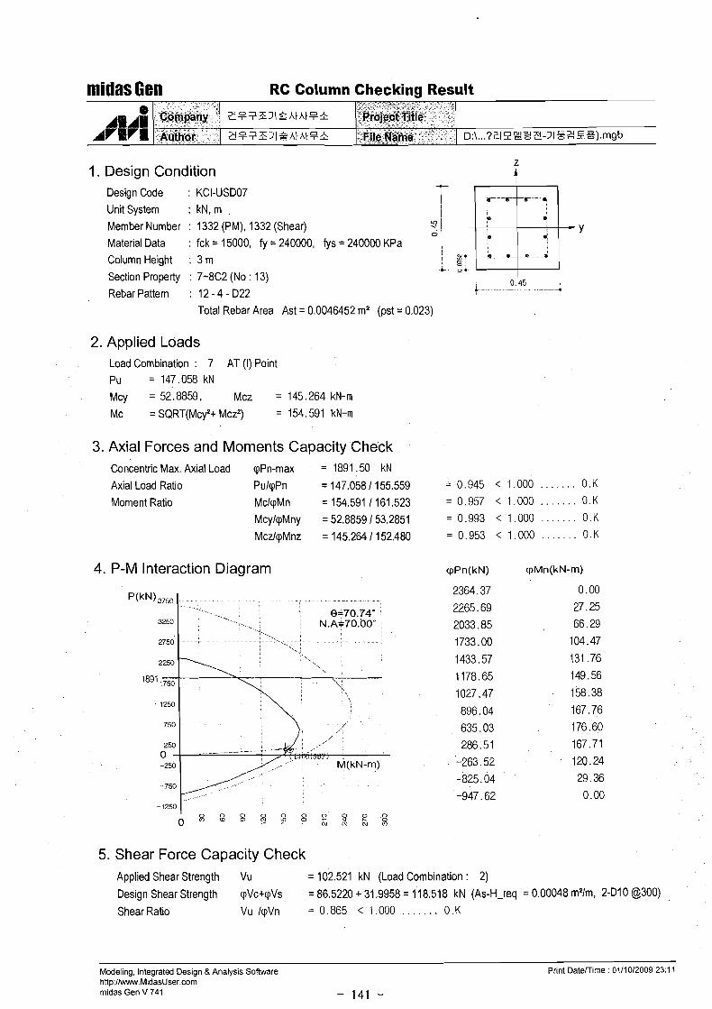
midas Gen RC Column Checking Result
1. Design Condition Design Code : KCI-USD07 Unit System : k ~ , m .
i Fie .;
Member Number : 1332 (PM), 1332 (Shear) ? 1 0 / * + Y
Material Data : fck = 15000, fy = 240000, fys = 240000 KPa I
Column Height : 3 m : y- d. . e . . . . e. . + 1 0 -c. ,A.
Section Property : 7-8C2 (No : 13) 0.45
Rebar Pattern : 12 - 4 - D22 . - - .- 4
Total Rebar Area Ast = 0.0046452 m2 (pst = 0.023)
2. Applied Loads Load Combination : 7 AT (I) Point Pu = 147.058 kN
Mcy = 52.8859, Mcz = 145.264 kN-m
Mc = SQRT(McyZ+ MczZ) = 154.591 kN-m
3. Axial Forces and Moments Capacity Check Concentric Max. Axial Load qPn-max = 1891 .50 kN Axial Load Ratio PulqPn = 147.058 1 155.559 = 0.945 < 1.000 . . . . . . . 0.K
Moment Ratio MclqMn = 154.591 1 161.523 = 0.957 < 1.000 . . . . . . . 0.K
McylqMny = 52.8859 1 53.2851 = 0.993 < 1.000 . . . . . . . 0.K
MczlqMnz = 145.264 1 152.480 = 0.953 < 1.000 . . . . . . . 0.K
4. P-M Interaction Diagram cppn(k~) c p ~ n ( k ~ - m )
5. Shear Force Capacity Check Applied Shear Strength Vu = 102.521 kN (Load Combination : 2) Design Shear Strength qVc+qVs = 86.5220 + 31.9958 = 118.518 kN (As-H-req = 0.00048 m21m, 2-D10 @300)
Shear Ratio Vu IqVn = 0.865 < 1.000 . . . . . . . 0 .K
Modeling, Integrated Design &Analysis Software http:llwww.MidasUser.corn rnidas Gen V 741 - 141 -
Print Datemime : 0111012009 23 : l l

midas (;en RC Column Checking Result
I. Design Condition Design Code : KCI-USD07 j .e . = . . . . . r- .....
Unit System : kN, m 6 ..
Member Number : 189 (PM), 186 (Shear) +- 6 , j i 9
Y Material Data : fck = 15000, fy = 240000, fys = 240000 KPa 9
I Column Height : 4.2 m &- L... *..- ..* . . .4
Section Property : - lC1 (No : 2) 0.7
Rebar Pattern : 12 - 4 - D22 t 4 Total Rebar Area Ast = 0.0046452 m2 (pst = 0.009)
2. Applied Loads Load Combination : 2 AT (I) Point Pu = 4094.53 kN
Mcy =-41.432, Mcz = 9.37893 kN-m
Mc = SQRT(Mcy2+ Mcz2) = 42.4798 kN-m
3. Axial Forces and Moments Capacity Check Concentric Max. Axial Load qPn-max = 3797.62 kN
Axial Load Ratio PulqPn = 4094.53 13797.62 = 1.078 > 1.000 . . . . . . N.G
Moment Ratio MclqMn = 42.4798 146.9472 = 0.905 < 1.000 . . . . . . . 0.K
McylqMny = -41.432 1 45.8673 = 0.903 < 1.000 . . . . . . . 0.K
MczlqMnz = 9.37893 1 10.01 15 = 0.937 < 1.000 . . . . . . . 0.K
4. P-M Interaction Diagram cppn(k~) CPM~(~N-m)
5. Shear Force Capacity Check Applied Shear Strength Vu = 57.2687 kN (Load Combination : 8)
Design Shear Strength qVc+qVs = 274.270 + 53.3948 = 327.665 kN (As-H-req = 0.00048 m21m, 2-Dl0 @300)
Shear Ratio VuIqVn =0 .175 <1.000 . . . . . . . 0.K
Modeling, Integrated Design & Analysis Software http://r,ww.MidasUser.com midas Gen V 741 - 142 -
Print Datemime : 01/10/2009 23:ll

midas Gen RC Column Checking Result
1. Design Condition Design Code : KCI-USD07
Unit System : kN, m ! t
Member Number : 205 (PM), 177 (Shear) 0 1 Y
Material Data : fck = 15000, fy = 240000, fys = 240000 KPa
Column Height : 4.2 m
Section Property : -1 C2 (No : 3) 0.65
Rebar Pattern : 12 - 4 - D22 - 4
-
Total Rebar Area Ast = 0.0046452 mZ (pst = 0.01 1)
e l l l ~
Armrfl
2. Applied Loads Load Combination : 2 AT (I) Point Pu = 1878.07 kN
Mcy = -2.5194. Mcz = 34.2768 kN-m
Mc = SQRT(McyZ+ Mcz2) = 34.3692 kN-m
3. Axial Forces and Moments Capacity Check
Company
author
Concentric Max. Axial Load qPn-max = 3350.10 kN
Axial Load Ratio PulqPn = 1878.07 13350.10 = 0.561 < 1.000 . . . . . . . 0.K
Moment Ratio MclqMn = 34.3692 1 73.5479 = 0.467 < 1.000 . . . . . . . 0 . K McylqMny = -2.51 94 1 5.49028 = 0.459 < 1.000 . . . . . . . 0.K
MczlqMnz = 34.2768 173.3427 = 0.467 < 1.000 . . . . . . . 0.K
4. P-M Interaction Diagram cpPn(kN) V M ~ ( ~ N - m )
2 ? 7 Z S 3 l S A t A t F h
2 ? 7 z 3 1 2 h t h t B &
5. Shear Force Capacity Check Applied Shear Strength Vu = 60.3276 kN (Load Combination : 10)
Design Shear Strength qVc+qVs = 194.988 + 49.1 150 = 244.103 kN (As-H-req = 0.00048 m21m, 2-Dl0 @300)
Shear Ratio Vu IqVn = 0.247 < 1.000 . . . . . . . 0 . K
Modeling, Integrated Design & Analysis Software Print Daterrime : 0111012009 23:l l http:llwww.MidasUser.com midas Gen V 741 - 143 -
Project Title
-File Name D:\. .?2 IPP ' -dZ-3 IS2EQ) .mgb

millas Gen RC Column Checking Result
1. Design Condition Design Code : KCI-USD07
Unit System : kN, m Member Number : 351 (PM), 348 (Shear) + 1
O ! Y Material Data : fck = 15000, fy = 240000, fys = 240000 KPa * ..
e l~,m A B W 8
Column Height : 3 4 m L%I* * 1 . Section Property : 1 C1 (110 : 4) 0
+ 0.7 Rebar Pattern : 12 - 4 - D22
Total Rebar Area Ast = 0.0046452 mZ (pst = 0.009)
Company
Author
2. Applied Loads
D:\ ... ??lP22e-31Sz'dE).mgb
z $ ? n ) C h t h t q h
???Z3lf htht8r?r
Load Combination : 2 AT (I) Point Pu =3511.79kN
Mcy = -4.2730. Mcz = 12.0779 kN-m
Mc = SQRT(McyZ+ Mcz2) = 12.8115 kN-m
<$k< - " '
'Pajen rmi' File Name
3. Axial Forces and Moments Capacity Check Concentric Max. Axial Load qPn-max = 3797.62 kN
Axial Load Ratio PulqPn = 351 1.79 1 3797.62
IWoment Ratio MclqMn = 12.81 15 1 17.6022
McylqMny = -4.2730 16.13527
MczkqMnz = 12.0779 I 16.4984
4. P-M Interaction Diagram
5. Shear Force Capacity Check Applied Shear Strength Vu = 116.249 kN (Load Combination : 7) Design Shear Strength qVc+qVs = 259.160 + 53.3948 = 312.555 kN (As-H-req = 0.00048 m21m, 2-Dl0 @300)
Shear Ratio Vu IqVn = 0.372 < 1.000 . . . . . . . 0.K
Modeling, Integrated Design & Analysis Software Print Datemime : 0111012009 23:11 http:llwww.MidasUser.corn rnidas Gen V 741 - 144 -

millas Gen RC Column Checking Result
1. Design Condition Design Code : KCI-USD07 Unit System : kN, m Member Number : 362 (PM), 339 (Shear) Material Data : fck = 15000, fy = 240000, fys = 240000 KPa
Column Height : 3.4 m Section Property : 1 C2 (No : 5)
0.65 Rebar Pattern : 12 - 4 - D22 , . . ~ . . - -. 4
Total Rebar Area Ast = 0.0046452 mZ (pst = 0.01 1)
2. Applied Loads Load Combination : 15 AT (J) Point Pu =-361.84kN
Mcy = 68.9439, Mcz = 91.5228 kN-m
Mc = SQRT(McyZ+ MczZ) = 114.585 kN-m
3. Axial Forces and Moments Capacity Check Concentric Max. Axial Load qPn-max = 3350.10 kN
Axial Load Ratio PulqPn = -361.84 1-483.90 = 0.748 < 1.000 . . . . . . . 0.K
Moment Ratio MclqM n = 114.585 1 154.360 = 0.742 < 1.000 . . . . . . . 0.K
McylqMny = 68.9439 1 91.71 55 = 0.752 < 1.000 . . . . . . . 0.K
McdqMnz = 91.5228 1 124.158 = 0.737 < 1.000 . . . . . . . 0.K
4. P-M Interaction Diagram cppn(kN) c p ~ n ( k ~ - m )
5. Shear Force Capacity Check Applied Shear Strength Vu = 108.605 kN (Load Combination : 10)
Design Shear Strength cpVc+qVs = 225.433 + 49.1 150 = 274.548 kN (As-H-req = 0.00048 mYm, 2-Dl0 @300)
Shear Ratio Vu IqVn = 0.396 < 1.000 . . . . . . . 0 .K
Modeling, Integrated Design & Analysis Software Print DateTTirne : 0111 012009 23:ll http://www.MidasUser.corn midas Gen V 741 - 145 -

midas Gen RC Column Checking Result
I. Design Condition Design Code : KCI-USD07 Unit System : kN, m Member Number : 491 (PM), 488 (Shear) a t a Y Material Data ' fck = 15000, fy = 240000, fys = 240000 KPa I
Column Height : 3 m %*- c 4- El-
Section Property : 2C1 (No : 6) 0 6
Rebar Pattern : 12 - 4 - D22 1 - . -- - 4
Total Rebar Area Ast = 0.0046452 m2 (pst = 0.013)
2. Applied Loads Load Combination : 2 AT (I) Point pu = 3093.44 kN Mcy = 6.21838, Mcz = 4.75651 kN-m
Mc = SQRT(Mcy2+ Mcz2) = 7.82896 kN-m
3. Axial Forces and Moments Capacity Check Concentric Max. Axial Load qPn-max = 2935 72 kN
Axial Load Ratio PulqPn = 3093.44 12935.72 = 1054 1 .000 . . . N.G
Moment Ratio MclqMn = 7.82896 19.16186 = 0.855 < 1.000 . . . . 0.K
McylqMny = 6.21838 17.16279 = 0.868 < 1.000 . . . . . . 0 .K
MczlqMnz = 4.75651 15.71263 = 0.833 < 1.000 . . . . . . 0.K
4. P-M Interaction Diagram cppn(k~) PM~(~N-m)
5. Shear Force Capacity Check Applied Shear Strength Vu = 81.5106 kN (Load Combination : 7)
Design Shear Strength qVc+qVs = 192.430 +44.8352 = 237.265 kN (As-H-req = 0.00048 mYm, 2-Dl0 @300)
Shear Ratio Vu IvVn = 0.344 < 1.000 . . . . . . . 0 .K
Modeling, Integrated Design & Analysis Software Print Datemime : 0111 012009 23:ll http:llwww.MidasUser.com midas Gen V 741 - 146 -
1 . Design Condition Design Code : KCI-USD07
Unit System : klV, m
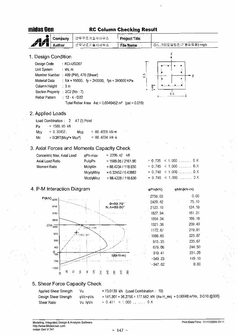
Member Number : 499 (PM), 476 (Shear) LD 1 : .miy 0 '
Material Data : fck = 15000, fy = 240000, fys = 240000 KPa 1 Column Height : 3 m \ P
A "& Section Property : 2C2 (No : 7)
0 5 Rebar Pattern : 12 - 4 - 022
+--. . - --- ---(
Total Rebar Area Ast = 0.0046452 m2 (pst = 0.01 9)
midas Gem RC Column Checking Result
2. Applied Loads Load Combination : 2 AT (I) Point Pu =1589.95kN
Mcy = 0.32452, Mcz = 88.4228 kN-rn
MC = SQRT(Mcy2+ Mcz2) = 88.4234 kN-m
0 4m41
AfVr1%1
3. Axial Forces and Moments Capacity Check Concentric Max. Axial Load cpPn-max = 2206.42 kN
Axial Load Ratio PulcpPn = 1589.95 12161.90 =0 .735 < 1.000 . . . . . . . 0.K
Moment Ratio MclcpMn = 88.4234 1 11 8.630 = 0.745 < 1.000 . . . . . . . 0.K
McylcpMny = 0.32452 i 0.43882 = 0.740 < 1.000 . . . . . . . 0.K
MczlcpMnz = 88.4228 1 11 8.630 = 0.745 < 1.000 . . . . . . . 0.K
4. P-M Interaction Diagram cppn(k~) V M ~ ( ~ N - m )
D : \ . . . ? Z l P 2 S ~ - 3 1 % 2 ~ Q ) mgb
Company
Author
5. Shear Force Capacity Check Applied Shear Strength Vu = 73.01 39 kN (Load Combination : 10)
Design Shear Strength cpVc+cpVs = 141.307 + 36.2756 = 177.582 kN (As-H-req = 0.00048 mYm, 2-Dl0 @300)
Shear Ratio VuIcpVn =0 .411 < 1 0 0 0 . . . . O K
Modeling, Integrated Design & Analysis Software Print Datemime : 0111012009 23:11 http:llwww.MidasUser.com midas Gen V 741 - 147 -
?!F?Z12htht9+
2F?Z112htAtF*
Project Title
File Name

fflidas Gen RC Column Checking Result
1. Design Condition Design Code : KCI-USD07 Unit System : kN, m Member Number . 630 (PM), 627 (Shear) LD 1
0 I I Material Data : fck = 15000, fy = 240000, fys = 240000 KPa
b
Column Height : 3 m Section Property . 3C1 (No : 8)
0 55 Rebar Pattern : 12 - 4 - D22 + +
Total Rebar Area Ast = 0.0046452 mz (pst = 0.01 5)
2. Applied Loads Load Combination : 2 AT (I) Point Pu =2671.29kN Mcy = 6.24976, Mcz = 4.49579 kN-m
Mc = SQRT(McyZ+ Mczz) = 7.69881 kN-m
3. Axial Forces and Moments Capacity Check Concentric Max. Axial Load pPn-max = 2554.50 kN
Axial Load Ratio PulpPn = 2671.29 12554.50 Moment Ratio MclpMn = 7.69881 19.05703
McylpMny = 6.24976 1 7.351 94
MczkpMnz = 4.49579 1 5.28950
4. P-M Interaction Diagram
5. Shear Force Capacity Check Applied Shear Strength Vu = 97.1061 klV (Load Combination : 7)
Design Shear Strength pVc+pVs = 159.699 + 40.5554 = 200.254 kN (As-H-req = 0.00048 m21m, 2-Dl0 @300)
Shear Ratio Vu IpVn = 0.485 < 1.000 . . . . . . . 0.K
Modeling, Integrated Design & Analysis Software ht tp: l~.MidasUser.corn rnidas Gen V 741 - 148 -
Print DateTTirne : 01/1012009 23: l l

4 . Design Condition Design Code : KCI-USD07 Unit System : k ~ , m
m I @,- Member Number : 638 (PM), 615 (Shear) z I Y Material Data : fck = 15000, fy = 240000, fys = 240000 KPa 1 C
Column Height : 3 m i- 9 ' -' Section Property : 3C2 (No : 9) Rebar Pattern : 12 - 4 - D22
Total Rebar Area Ast = 0.0046452 m2 (pst = 0.021)
midas Gen RC Column Checking Result
2. Applied Loads Load Combination : 2 AT (J) Point Pu =1379.73kN Mcy = 39.3222. Mcz = -93.568 kN-m
Mc = SQRT(Mcy2+ Mcz2) = 101.495 kN-m
d l l l a
3. Axial Forces and Moments Capacity Check Concentric Max. Axial Load qPn-max = 2040.67 kN
Axial Load Ratio PulqPn = 1379.73 1 1812.51 =0.761 < 1.000 . . . . . . . 0.K
Moment Ratio MclqlWn = 101.495 1 131.236 = 0.773 < 1.000 . . . . . . . 0.K
McylqMny = 39.3222 150.7565 = 0.775 < 1.000 . . . . . . . 0.K
MczlqMnz = -93.568 1 121.024 = 0.773 < 1.000 . . . . . . . 0.K
Cornpafig
4. P-M Interaction Diagram rppn(kN) r p ~ n ( k ~ - m )
5. Shear Force Capacity Check Applied Shear Strength Vu = 79.1 641 kN (Load Combination : 10)
Design Shear Strength qVc+qVs = 125.264 + 36.2756 = 161.539 kN (As-H-req = 0.00048 m21m, 2-Dl0 @300)
Shear Ratio Vu IqVn = 0.490 < 1.000 . . . . . . . 0.K
Modeling, Integrated Design & Analysis Software Print Datemime : 0111012009 23:ll http:llwww.MidasUser.com midas Gen V 741 - 149 -
D:\ ... ?2lPPgP-J182%8).mgb
3P7Z3lf hthtB*
d V w ! l g - - Project Title - File Name ,-

1. Design Condition Design Code : KCI-USD07 . (I . . . . . . . . . . .*:
Unit System : kN, m 1 Member Number : 769 (PM), 766 (Shear)
I - p, - " I 0 , Y
0:
Material Data : fck = 15000, tj = 240000, t j s = 240000 KPa ............. ... ........ ColumnHeight : 3 rn . " @ . . 4 .* -1- 2
Section Property : 4C1 (No : 10) 0.5
Rebar Pattern : 12 - 4 - D22 i , - -i
Total Rebar Area Ast = 0.0046452 m2 (pst = 0.019)
midas Cell RC Column Checking Result
2. Applied Loads Load Combination : 2 AT (I) Point Pu = 2252.26 kN
Mcy = 8.66988, Mcz = 5.58810 kN-m
Mc = SQRT(McyZ+ MczZ) = 10.3147 kN-m
8 4 ~ ~ 4
ArHrI
3. Axial Forces and Moments Capacity Check Concentric Max. Axial Load qPn-max = 2206.42 kN
. . . . . Axial Load Ratio PulqPn = 2252.26 12206.42 = 1021 > 1.000 N .G
. . . . . . . Moment Ratio MclqMn = 10.3147 112.7329 = 0.810 < 1.000 0.K
. . . . . . . McylqMny = 8.66988 1 10.6967 = 0.811 < 1.000 0.K . . . . . . MczkqMnz = 5.58810 1 6.90714 = 0.809 i 1.000 0.K
Company
Author
4. P-M Interaction Diagram cppn(k~) V M ~ ( ~ N - m )
... D:\ ??1PE22 Z - 3 1 Z 2 S3) mgb
3?;15JIBhtht?+
3 l t
5. Shear Force Capacity Check
'Projekt Title
,file@ame
Applied Shear Strength Vu = 87.9541 kN (Load Combination : 7)
Design Shear Strength qVc+qVs = 129.761 + 36.2756 = 166.036 kN (As-H-req = 0.00048 mzlm, 2-Dl0 @300) . . . . . . . Shear Ratio Vu IpVn = 0.530 i 1.000 0.K
Modeling, Integrated Design & Analysis Software Print DateKirne : 01110/2009 23:11 http:llwww.MidasUser.corn rnidas Gen V 741 - 150 -

millas Gen RC Column Checking Result
1. Design Condition Design Code : KCI-USD07 I
Unit System : kN, m Member Number : 754 (PM), 754 (Shear)
-- @, * 3 ' 0 1 Y
Material Data : fck = 15000, fy = 240000, fys = 240000 KPa 31
Column Height : 3 m .- :*
Section Property : 4C2 (No : 11) o 5 t - - - 4 Rebar Pattern . 12 - 4 - D22
Total Rebar Area Ast = 0.0046452 m2 (pst = 0.021)
2. Applied Loads Load Combination : 10 AT (I) Point Pu = 926.500 kN
Mcy =38.2816, Mcz =-119.59kN-m
Mc = SQRT(Mcy2+ Mcz2) = 125.564 kN-m
3. Axial Forces and Moments Capacity Check Concentric Max. Axial Load pPn-max = 2040.67 kN
Axial Load Ratio PulpPn = 926.500 11319.14 = 0.702 < 1.000 . . . . . . . 0.K
Moment Ratio MclpMn = 125.564 1 175.908 = 0.714 < 1.000 . . . . . . . 0.K
McylpMny = 38.2816 151.9331 = 0.737 < 1.000 . . . . . . . 0.K
MczkpMnz = -1 19.59 1 168.067 = 0.712 < 1.000 . . . . . . . 0.K
4. P-M Interaction Diagram cppn(k~) V M ~ ( ~ N - m )
5. Shear Force Capacity Check Applied Shear Strength Vu = 77.7043 kN (Load Combination : 10)
Design Shear Strength pVc+pVs = 119.483 + 36.2756 = 155.759 kN (As-H-req = 0.00048 m21m, 2-Dl0 @300)
Shear Ratio Vu IpVn = 0.499 < 1.000 . . . . . . . 0.K
Modeling, Integrated Design &Analysis Software http:llwww.MidasUser.corn rnidas Gen V 741 - 151 -
Print Datemime : 0111012009 23:11
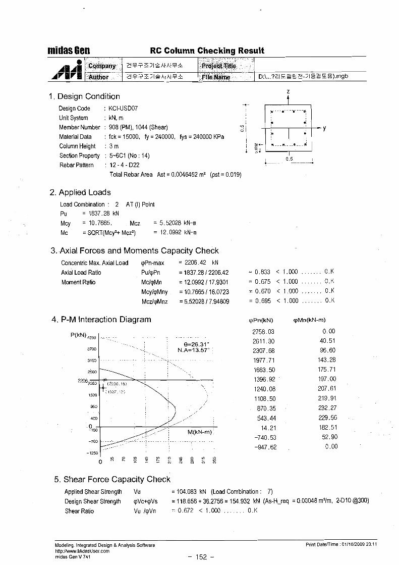
midas Gen RC Column Checking Result
1. Design Condition Design Code : KCI-USD07
Unit System : kN, m Member Number : 908 (PM), 1044 (Shear) Y Material Data : fck = 15000, fy = 240000, fys = 240000 KPa Column Height : 3 m
Section Property : 5-6C1 (No : 14) 0.5 i Rebar Pattern : 12 - 4 - D22
Total Rebar Area Ast = 0.0046452 m2 (pst = 0.019)
-
2. Applied Loads Load Combination : 2 AT (I) Point Pu =1837.28kN
Mcy = 10.7665, . Mcz = 5.52028 kN-m
Mc = SQRT(Mcy2+ MczZ) = 12.0992 kN-m
3. Axial Forces and Moments Capacity Check
D:\ ... ? z ~ e s g e - ~ ~ z z ~ ~ ) . m g b
Concentric Max. Axial Load pPn-max = 2206.42 kN
Axial Load Ratio PulpPn = 1837.28 1 2206.42
Moment Ratio MclpMn = 12.0992 1 17.9301
McylpMny = 10.7665 1 16.0723
MczlqMnz = 5.52028 17.94809
0 ~ ~ 1 1
A V W l
4. P-M Interaction Diagram
2 i F ? E J l 4 h t h t ? &
3F.-;1ZJIQhthtB&
C~rflpany
Author
-1250 1.' " l o w "l 0 ombg~~~~w3W
Prdje~€%itlg - . File:NaIne
5. Shear Force Capacity Check Applied Shear Strength Vu = 104.083 kN (Load Combination : 7)
Design Shear Strength pVc+pVs = 118.656 + 36.2756 = 154.932 kN (As-H-req = 0.00048 mYm, 2-Dl0 62300)
Shear Ratio Vu IpVn = 0.672 < 1.000 . . . . . . . 0.K
Modeling, Integrated Design & Analysis Software Print Daterrime : 0111012009 23:11 http:llwww.MidasUser.corn rnidas Gen V 741 - 152 -
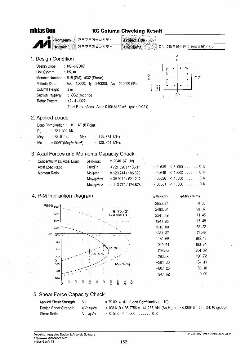
I. Design Condition Design Code : KCI-USD07 .....
Unit System : kN, m Member IVumber : 915 (PM), 1032 (Shear) / Y
Material Data : fck = 15000, fy = 240000, fys = 240000 KPa
Column Height : 3 m Section Property : 5-6C2 (No : 15) i 0.5 ...d
Rebar Pattern : 12 - 4 - 022
millas Gen RC Column Checking Result
Total Rebar Area Ast = 0.0046452 mz (pst = 0.021)
2. Applied Loads
e 11111
AVBra
Load Combination : 8 AT (I) Point Pu = 721.590 kN
Mcy = 38.9119, Mcz =113.774kN-m
Company ~ ~ t h o i ' .
3. Axial Forces and Moments Capacity Check
D:\ ... ? z ~ n g e a - ~ ~ z z s ~ ) . w b
? !??ZJ l2AtAt?b
ZB?ZJIQAIAIF*
Concentric Max. Axial Load qPn-max = 2040.67 kN
Axial Load Ratio PulqPn = 721.590 11135.17 Moment Ratio MclqlWn = 120.244 1 185.390
McylqMny = 38.91 19 162.1212
MczlwMnz = 1 13.774 1 174.673
".P,i@git,Tit~e$ w - *a " - ' ~ i @ & ~ m & . . *..
4. P-M Interaction Diagram
5. Shear Force Capacity Check Applied Shear Strength Vu = 79.0314 kN (Load Combination : 10)
Design Shear Strength qVc+qVs = 108.010 + 36.2756 = 144.285 kN (As-H-req = 0.00048 m21m, 2-010 @300)
Shear Ratio Vu IqVn = 0.548 < 1.000 . . . . . . . 0 .K
Modeling, Integrated Design &Analysis Software http://www.MidasUser.com midas Gen V 741 - 153 -
Print Daterrime : 0111012009 23 : l l
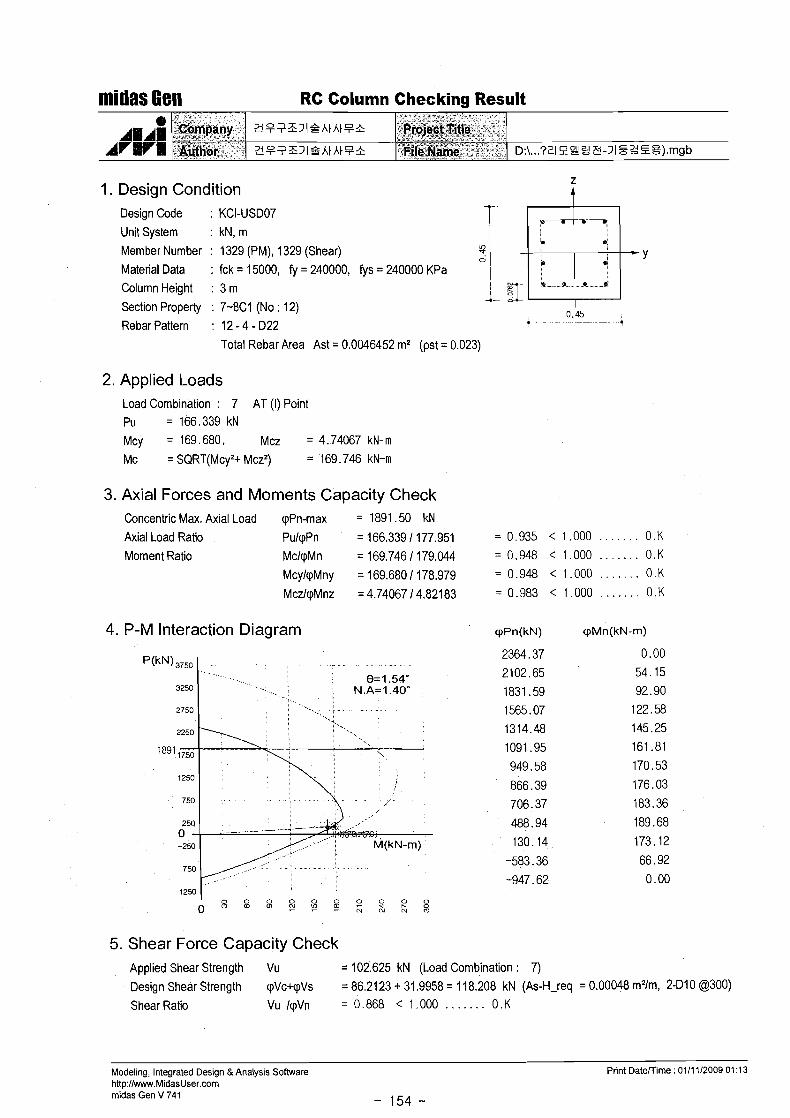
midas Gen RC Column Checking Result
1. Design Condition Design Code : KCI-USD07 Unit System : kN, m
Member Number : 1329 (PM), 1329 (Shear) S
Material Data : fck = 15000, fy = 240000, fys = 240000 KPa o 1 m-y Column Height : 3 m
Section Property : 7-8C1 (No : 12) 1- 9
0.45 Rebar Pattern : 12 - 4 - D22 9
-- -- -4 Total Rebar Area Ast = 0.0046452 m2 (pst = 0.023)
2. Applied Loads Load Combination : 7 AT (I) Point Pu =166.339kN Mcy = 169.680. Mcz = 4.74067 kN-m
Mc = SQRT(Mcy2+ Mcz2) = 169.746 kN-m
3. Axial Forces and Moments Capacity Check Concentric Max. Axial Load qPn-rnax = 1891 .50 kN
Axial Load Ratio PulqPn = 166.339 1 177.951 = 0.935 < 1.000 . . . . . . . 0.K
Moment Ratio MclqMn = 169.746 1 179.044 = 0.948 < 1.000 . . . . . . . 0.K McylqMny = 169.680 1 178.979 = 0.948 < 1.000 . . . . . . . 0.K
MczlqMnz = 4.74067 14.82183 = 0.983 < 1.000 . . . . . . . 0.K
4. P-M Interaction Diagram cppn(k~) c p ~ n ( k ~ - m )
5. Shear Force Capacity Check Applied Shear Strength Vu = 102.625 kN (Load Combination : 7) Design Shear Strength qVc+qVs = 86.2123 + 31.9958 = 118.208 kN (As-H-req = 0.00048 m21m, 2-Dl0 @300)
Shear Ratio Vu IqVn = 0.868 < 1.000 . . . . . . . 0 .K
Modeling, Integrated Design & Analysis Software http:llwww.MidasUser.com midas Gen V 741 - 154 -
Print Datemime : 0111 112009 01:13

millas Gem RC Beam Strength Checking Result
1. Design Information Design Code : KCI-USDO7 Unit System : kN, m Material Data : fck = 15000, fy = 240000, fys = 240000 KPa Beam Span : 6.12 m
Section Property : 2G1 (No : 30)
2. Section Diagram
[END-I] [END-J]
TOP : 5-D22 TOP : 3-D22 TOP : 5-D22
BOT : 3-D22 BOT : 5-D22 BOT : 3-D22
STIRRUPS : 2-Dl0 @200 STIRRUPS : 2-Dl0 a200 STIRRUPS : 2-Dl0 @200
3. Bending Moment Capacity . - ........ - - - -............... - - .. - ... -. .. .- . - ... .. ....... ..-.......
- MID END- J ............ .. .................. ... ...........
(-) Load Combination No.
Moment (Mu) Strength (cpMn)
Check Ratio (MulcpMn)
(+) Load Combination No.
Moment (Mu) Strength (cpMn)
Check Ratio (MulcpMn)
Using Rebar Top (As-top)
Using Rebar Bot (As-bot)
4. Shear Capacity - .... . . . - - . . . - - .... - ... - . - . - . -. ... - - ....... - - -. - - - - - - -.
END-I --1
- -- - :MID-- . ............
, END-J
Load Combination No.
Factored Shear Force (Vu )
Shear Strength by Conc.(cpVc)
Using Shear Reinf. (AsV)
Using Stirrups Spacing
Check Ratio
Modeling, Integrated Design & Analysis Software http://w.MidasUser.com midas Gen V 741
- 155 -
Print Daterrime : 03/05/2009 13:55

1. Geometry and Materials + 1600-- --.+ Design Code : KCI-USDO3 (Build.) -r... 31 Stress Proflle : Parabolic
0 1
%! Material Data : fck = 15 MPa ( P I = 0.850) i
midas Set Beam Strengthening 1261 (Xi1 U, Eta &!)I
f,= 240, f,, = 240 MPa
Section : 450 * 350 mm (hf=120, bf=1600 mm)
Top Bar (Layer I ) : 3 - 022 (dr = 60 mm)
Top Bar (Layer 2) : 2 - 022 (dr = 11 0 mm)
Bot. Bar (Layer 1) : 2 - 022 (ds = 60 mm)
Stirrups : 2 - D 1 0 @ 3 0 0
e AlAU ru
2. Strengthening Materials
3. Member Force and Moment -. Mu = -138.0 kN-m Vu = 110.0 kN
&&pa@? c~pjidntir
4. Check Tension Reinforcement -. AS = z(Abar+&t~*(fst~/fy)* P ) = 3876 mm2
-. AS' = I(Abar1+&t~'*(fst~/fy)* P ) = 3076 mm2
-. dc = (&*tdct)/(&) = 158 mm
-. dc = (As'*Edcc)/(As') = 28mm
-. d = H-dc = 292mm
z :" -- , ' <
F4fiT%i4@;e;.
-. p b = 0.85 P1(f '~/fy)*600/(600+f~) = 0.0323
-. fabl = 600 - dc'/d1*(600+fy) = 543.2 MPa
-. fsb = Min [fsbl, fyl = 240.0 MPa
- . A , - , = 0.75p,(H-ds)BtAs'*fsE/f, = 5549 > 3876mm2 . . . . . . . 0 . K
5. Bending Moment Capacity - Before Strengthening -. Neutral Axis Depth c = 87 mm
-. Compression : Concrete Cc = 328.2 kN
-. Compression : Rebar Cs = 136.2kN
-. Tension : Rebar Ts = -464.5 kN
-. Strength Reduction Factor 0 = 0.850
-. Design Moment Strength DMn= -128.7 kN-m - . <?.:.;;!y7!*,, ;,>: ~, , .>:! : >.." :.<<zl<:<; ; '..;I::/{i> !$;. .:. 1 ,072 ;, 1 ,[y;') <>?:.,.. ' ' . . . . . . . ,, ;.: v;r>:'>::
midas Set V 3.3.4 http:l/w.MidasUser.com
Date : 03/05/2009 - 1 1 2 -
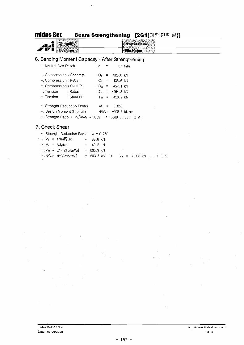
6. Bending Moment Capacity - After Strengthening -. Neutral Axis D e ~ t h c = 87 mm
midas Set Beam Strengthening [2Gl (Xil 3 3 2)]
-. Compression : Concrete Cc = 328.0 kN
-. Compression : Rebar CS = 135.6kN
-. compression : Steel PL Cstl = 457.1 kN
-. Tension : Rebar Ts = -464.5 kN
-. Tension : Steel PL Ts,l = -456.2 kN
* ~ 4 1
-. Strength Reduction Factor 0 = 0.850
-. Design Moment Strength OMn= -208.7 kN-m
-. Strength Ratio : M,/OM, = 0.661 < 1.000 . . . . . . . 0 . K.
7. Check Shear -. Strength Reduction Factor 0 = 0.750
-. Vc = 1 /6f lBd = 83.6 kN
-. Vs = AvfYd/s = 42.2 kN
-. VSII = 0 * [2Ts11fst1Wst11 = 665.3 kN
-. 0Vn= @(Vc+vs+Vs:~) = 593.3 kN V, = 110.0 kN ---> O.K.
L .I % <--" 2
+jNqi$"f *ii"z~G:
midas Set V 3.3.4
Date : 03/05/2009
,+ .x - ?"* . - , - .r
-<-* - ' *
.&!go~g$t &yqe20s %:
-jfZ&i$a~Q~~ --w---z - . ';' . z 2 " " -
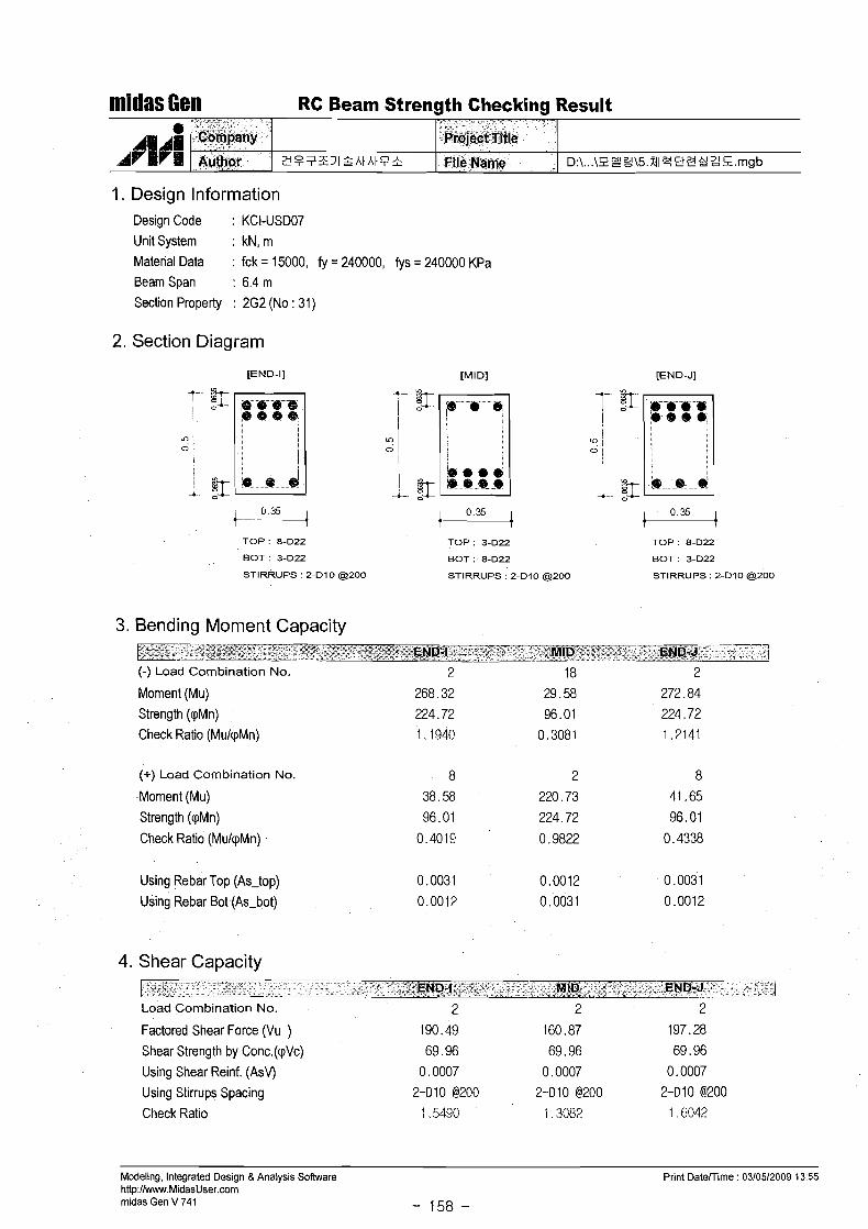
midas Gen RC Beam Strength Checking Result
I. Design Information
- -
Design Code : KCI-USD07
Unit System : kN, m
Material Data : fck = 15000, fy = 240000, fys = 240000 KPa Beam Span : 6.4 m
Section Property : 2G2 (No : 31)
e ANAN
A r H m
2. Section Diagram
[END-I] [MI Dl
T 5 I 1
' ,
~ b i i p ~ y Allfhor
b e e s
TOP : 8-D22 TOP : 3-D22
BOT : 3-D22 BOT : 8-D22
STIRRUPS ' 2-Dl 0 (9200 STIRRUPS : 2-Dl0 (9200
Z i ? ? Z I I P h t h t P &
[END-J]
TOP : 8-D22
BOT : 3-D22
STIRRUPS : 2-Dl0 a 2 0 0
Prdject"T.itle
File Name
3. Bending Moment Capacity
D:\...\PY3\5.MIq9Z2ZS.mgb
(-) Load Combination No.
Moment (Mu) Strength (cpMn)
Check Ratio (MulpMn)
(+) Load Combination No.
Moment (Mu)
Strength (cpMn)
Check Ratio (MulpMn)
Using Rebar Top (As-top)
Using Rebar Bot (As-bot)
4. Shear Capacity
Load Combination No. 2 2 2
Factored Shear Force (Vu ) 190.49 160.87 197.28
Shear Strength by Conc.(cpVc) 69.96 69.96 69.96
Using Shear Reinf. (AsV) 0.0007 0.0007 0.0007
Using Stirrups Spacing 2-Dl0 (3200 2-010 @200 2-Dl0 @200
Check Ratio I ,5490 i ,3082 1 6043
Modeling, Integrated Design 8 Analysis Software http://www.MidasUser.com midas Gen V 741 - 158 -
Print Daterrime : 03/05/2009 13:55
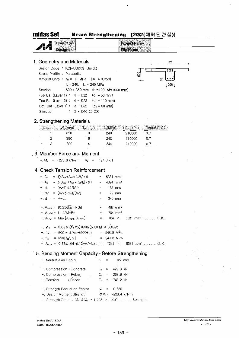
1. Geometry and Materials
midas Set Beam Strengthening [2G2(X4 Et Z S ) ]
Design Code : KCI-US003 (Build.)
Stress Profile : Parabolic
Material Data : fck = 15 MPa ( 4 1 = 0.850)
4 "AM
AT m r
fy = 240, fys = 240 MPa
Section : 500 * 350 mm (hf=120, bf=1600 mm) Top Bar (Layer 1) : 4 - 022 (dr = 60 mm)
Top Bar (Layer 2) : 4 - 022 ( d ~ = 110 mm)
Bot. Bar (Layer 1) : 3 - D22 (de = 60 mm)
Stirrups : 2 - Dl0 @ 200
2. Strengthening Materials
*
p p i f @
' hg~$fii+.
- -
Location Ws1~(rnm) Tse(rnrn) bt(MPa1 EstdMPa) Reduc.F( 4)
* * " w " - :.r - * - " v \ '*
~@~ojl$f:~arne~ ,, ax z%- :Z - "- "
:;glk;gskwg- %*, z:S i
3. Member Force and Moment
4. Check Tension Reinforcement -. AS = x(Abar+kt~*(fs~t/fy)* ) = 5331 mm2
- A = x(Abar'+k~~'*(fs~~/fy)* 4 ) = 4324 mm2
-. dc = (As*xdcr)/(As) = 155 mm
-. dc' = (As1*xdcc)/(k') = 29mm
-. d = H-dc = 345mm
-. As.min1 = (0.25&/fy)*Bd = 487 mm2
-. As.min~= (1 .4/fy)*Bd = 704 mm2
-. As.-9 = Max [&.mirl. As.n)!r?l = 704 < 5331 mm' . . . . . . . O.K.
-. ,CJ~ = 0.85 4 ~(f 'c /fy)*600/1600+fy) = 0.0323
-. fsb' = 600 - dc'/d'*(600+fy) = 548.8 MPa
-. fsb = Min[fsbl, fyl = 240.0 MPa
-. = 0 .75~3(H-d~)B+A~'* f~c / f~ = 7241 > 5331 mm: . . . . . . . 0. K .
5. Bending Moment Capacity - Before Strengthening -. Neutral Axis Depth c = 127mm
-. Compression : Concrete Ce = 479.3 kN
-. Compression : Rebar Cs = 263.9 kN
-. Tension : Rebar Ts = -743.2 kN
-. Strength Reduction Factor 0 = 0.859
-. Design Moment Strength 0 Mn= -226.4 kN-m - . ; , .. . . -, . .... <.\, . ~,!,:i,'d:b$:, .. .=: 1 y , ; 2 > 1 ,$;;1~ , , , , , , , :;ji.,::nc'.i!. . -I. L, . .,...-l t i !
rnidas Set V 3.3.4 http://www.MidasUser.corn
Date : 03/05/2009 -112-
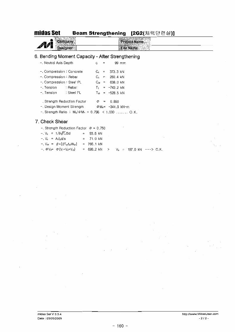
6. Bending Moment Capacity - After Strengthening -. Neutral Axis Depth c = 99 rnrn
midas Set Beam Strengthening [262(%414 9 3 g ) ]
-. Compression : Concrete Cc = 373.3 klV
-. Compression : Rebar Cs = 260.4 kN
-. Compression : Steel PL C,II = 638.0 kN
-. Tension : Rebar Ts = -743.2 kN
-. Tension : Steel PL T~II = -528.5 kN
-. Strength Reduction Factor @ = 0.850
-. Design Moment Strength @ Mn= -341.9 kN-m
-. Strength Ratio : M:,/@Mr = 0.798 < 1.000 . . . . . . . 0 . K
0 AM 1CCn
7. Check Shear -. Strength Reduction Factor @ = 0.750
-. Vc = 1 / 6 G B d = 93.8 kN
-. Vs = Avf,d/s = 71.0 kN
-. VSII = R * [2Ts,1fst1Wst1] = 766 . 1 kN
-.@Vn= @(Vc+Vs+Vsv) = 698.2kN > V, = 197.0kN ---> O.K.
.^_ . % r w
,3&3+ja/i 3 -+ik%: *+g-
& % w-
midas Set V 3.3.4 Date : 03/05/2009
@*;g6<~;;$$wz$~~?dy *
a ;Fqqs~g~&m.e~.- ,. X-XlaLZaJV-n --

midas Gel1 RC Beam Strength Checking Result
1. Design Information Design Code : KCI-USD07 Unit System : kN, m
Material Data : fck = 15000, fy = 240000, fys = 240000 KPa Beam Span : 6.1 2 m
Section Property : 2B1 (No : 33)
2. Section Diagram
[END-I]
TOP: 5fD22
BOT : 34222
STIRRUPS : 24310 a 2 0 0
TOP : 34222
BOT : 5-D22
STIRRUPS : 2-010 a 2 0 0
[END-J]
TOP ' 54322
BOT : 3.022
STIRRUPS. 2-Dl0 @200
3. Bending Moment Capacity
(-) Load Combination No.
Moment (Mu)
Strength (cpMn)
Check Ratio (MuIpMn)
(+) Load Combination No.
Moment (Mu)
Strength (pMn)
Check Ratio (MukpMn)
Usiug Rebar Top (As-top)
Using Rebar Bot (As-bot)
4. Shear Capacity
Load Combination No. 2 2 2
Factored Shear Force (Vu ) 124.27 89.84 118.44
Shear Strength by Conc.(pVc) 62.29 62.29 62.29
Using Shear Reinf. (AsV) 0.0007 0.0007 0.0007
Using Stirrups Spacing 2-010 @200 2-010 @ZOO 2-010 @200
Check Ratio 1.1350 0.8205 1 ,0817
Modeling, Integrated Design & Analysis Software
http://www.MidasUser.com midas Gen V 741 - 161 -
Print DateKime : 03/05/2009 13:55

1. Geometry and Materials i 1600 +
Design Code : KCI-USD03 (Build.)
Stress Profile : Parabolic T" Material Data : fck = 15 MPa ( P I = 0.850)
f, = 240, fYs = 240 MPa
Section : 450 * 350 mm (hf=120, bf=1600 mm) w
Top Bar (Layer 1) : 3 - 022 (dr = 60 mm)
Top Bar (Layer 2) ' 2 - 022 (dr = 1 1 0 mm)
Bot. Bar (Layer 1) : 3 - 022 (de = 60 mm)
Stirrups : 2 - D 1 0 @ 2 0 0
nlidas Set Beam Strengthening [2Bl ( f l l U, Et a S ) ]
2. Strengthening Materials
AlAsl ArelsH
Location Wsn(mm) Tsdmm) fs11(MPa) EdMPa) Reduc.F( P )
3. Member Force and Moment -. Mu = -146.0 kN-m Vu = 124.0 kN
"~aap&y, -, - . _ ,
~ e ~ i g n e r
4. Check Tension Reinforcement . As = z(Abar+&~~*(fst~/fy)* 0 ) = 4153 mm2
-. As' = x(Aba,'+&t~'*(fst~/fy)* P = 3186 mm2
-. dc = (As*xdc~)/(As) = 172 mm
-. dc' = (As1*xdcc)/(As') = 28 mm
-. d = H-dc = 278mm
~cijGtIkirne v:
File Name
-. As.mint = (0.25&/fy)*Bd = 393mm2
-. As.minn= (1.4/fy)*Bd = 568 mm2
-. AS.?? = Max [A.mlirl. Ar.airz] = 568 < 4153mmV.. . . . . . O.K .
-. , ~ b = 0.850 l(f1c/fy)*600/(600+f,) = 0.0323
-. fsb' = 600 - dc1/d'*(600+fY) = 545.1 MPa
-. fsb = Min[fSb1, fy l = 240.0 MPa
-. As, = 0.75p3(H-dc)B+k1*fSE/fY = 5541 > 4153 mm2 . . . . . . . 0 . K.
5. Bending Moment Capacity - Before Strengthening -. Neutral Axis Depth c = 80 mm
-. Compression : Concrete Cc = 301.6 kN
-. Compression : Rebar Cs = 162.9 kN
-. Tension : Rebar Ts = -464.5 kN
-. Strength Reduction Factor 0 = 0.850
-. Design Moment Strength @Mn= -129.0 kN-m -, .<,>: : , . . . >,., +; -< ... % : .
, ..,. ;::i i..,:,. : : :> :.. .. >' .. . 132 .> t , :;,::: . . . . . . . ., :; ::. i: .! ;: : .
midas Set V 3.3.4 http://www.MidasUser.com
Date : 03/05/2009 -112-

midas Set Beam Strengthening [2BI I
6. Bending Moment Capacity - After Strengthening -. Neutral Axis Depth c = 82 mm
-. Compression : Concrete Cc = 307.9 kN
-. Compression : Rebar Cs = 174.4 kN
-. compression : Steel PL CSII = 449.1 kN
-. Tension : Rebar TS = -464.5 kN
-. Tension : Steel PL Tstl = -466.9 kN
-. Strength Reduction Factor O = 0.850.
-. Design Moment Strength OMo= -209.5 kN-m
-. Strength Ratio : FII,I@M,, = 0.697 < 1.000 . . . . . . . 0. K.
7. Check Shear -. Strength Reduction Factor @ = 0.750
-.Vc = 1/6flBd = 83.6 kN
-. Vs = AvfydIs = 63.3kN
-. Vss = P * [2Ts11fsuWst1] = 665.3 kN
-. OVF O(V~+V,+V~~I) = 609.2 kN > Vu = 124.0 kN ---> O.K.
midas Set V 3.3.4 http://www.MidasUser.com
Date : 0310512009 - 21 2 -

midas Set Slab Capacity Table
1. Design Conditions Design Code : KCI-USD07
Material Data : fck = 15 MPa
: fy = 240 MPa Concrete Clear Cover : 20 mm
2. Slab Thk : 120 mm Short Direction Moment (Unit : kN-mlm)
0 1 0 0 @ I 2 0 @ I 5 0 @ I 8 0 ($200 (3230 @250 ($300 D l 0 12.9 10.9 8.8 7.4 6.7 5.8 5.4 4.5
Long Direction Moment @ l o 0 @ I 2 0 @ I 5 0 @ I 8 0 0 2 0 0 @230 @250 (3300
D l 0 11.3 9.5 7.7 6.5 5.9 5.1 4.7 4.0 010+013 14.8 12.6 10.3 8.7 7.9 6.9 6.4 5.3
D l 3 17.8 15.3 12.6 10.7 9.7 8.5 7.9 6.6
D13+D16 21.2 18.4 15.3 13.1 11.9 10.5 9.7 8.2
D l 6 < ,- 2 21.0 17.6 15.2 13.9 12.3 11.4 9.7 @Vc = 45.3 kN/m
rnidas Set V 3.3.4 http://www.MidasUser.com
Date : 03/05/2009

midas Set Slab Design [2Sl (Xi1 U, Eta S ) ]
1. Geometry and Materials Design Code : KCI-US007
Material Data : fck = 15 MPa
fy = 240 MPa 0
Slab Dim. : 3200 * 61 20 * 120 mm (cc = 20 mm) N Edge Beam Size : (D
61 = 350 X 450, 62 = 350 X 450 mm
2. Applied Loads w Dead Load : Wd = 4.5 kPa Live Load : WI = 6.0 kPa
W, = 1.2*Wd+1 . ~ * W I = 15.0 kPa
3. Check Minimum Slab Thk.
4. Reinforcement
5. Check Shear Stresses
Strength Reduction Factor QJ = 0.850
Strength Reduction Factor QJ= 0.750 Short Direction Shear
. . . . . V,,= 20.1 < @Vc= 45.7kN:m
Coefficient
Mu {kN-m/m)
0 (%I AI (mm2/m)
O.K.
Long Direction Shear V,, = 2.6 < QJV, = 40.3 kN/m . . . . . . . O.K.
rnidas Set V 3.3.4
Date : 03/05/2009
Min~mum
Ratio
0.200
240
Short Span
Cont. Cent.
0.086 0.037(0)
O.Oss(L)
10.5 6.8
0.600 0.379
572 36 1
Long Span
Cont. Cent.
0.006 0.002(0)
O.O04(L)
2.9 1.6
0.199 0.108
170 92
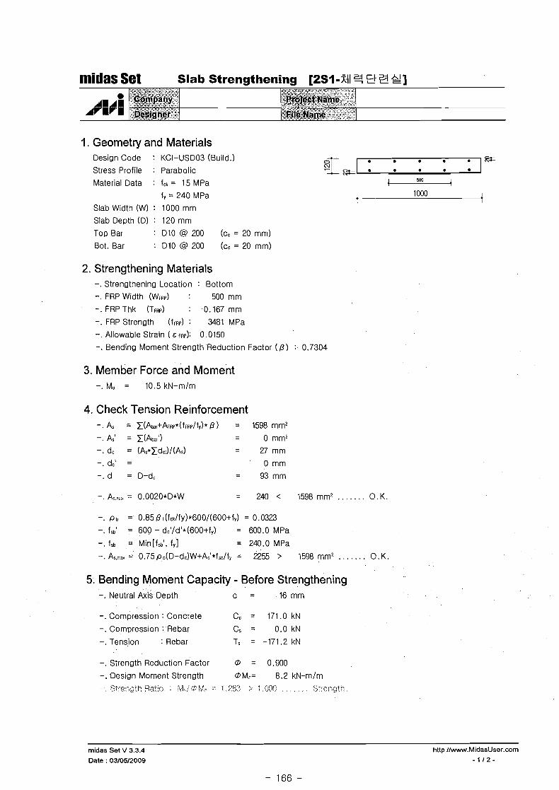
midas Set Slab Strengthening [2Sl-Xi1 U, Eli3 g ]
1. Geometry and Materials Design Code : KCI-USD03 (Build.) FJ= Stress Profile : Parabolic
Material Data : fct = 15 MPa 4 503 + f, = 240 MPa k-- 1 000 i
Slab Width (W) : 1000 mm
Slab Depth (0) : 120 mm
Top Bar : Dl0 @ 200 (cc = 20 mm)
Bot. Bar : D l0 @ 200 (cc = 20 mm)
2. Strengthening Materials -. Strengthening Location : Bottom
-. FRP Width (WFRP) : 500 mm
-. FRP Thk (TFRP) : 0.167 mm
-. FRP Strength (~FRP) : 3481 MPa
-. Allowable Strain ( t FRP): 0.0150
-. Bending Moment Strength Reduction Factor ( P I : 0.7304
3. Member Force and Moment -. Mu = 10.5 kN-m/m
4. Check Tension Reinforcement -. As = x(Abar+&RP*(fFRP/fy)* 0 ) = 1598 mm2
-. As' = x(Abar') - - 0 mm2
-. dc = (As*xdcl)/(As) = 27mm -.dc' = 0 mm
-. d = D-dc = 9 3 m m
-. As.sn = 0.0020*D*W = 240 < 1598mm2 . . . . . . . O.K.
-. p b = 0.85 P1(f~dfy)*600/(600+f~) = 0.0323
-. fsb' = 600 - dc'/d'*(600+f,) = 600.0 MPa
-. fsb = Min[fsbl, f y l = 240.0 MPa
-. AS-= = 0.75pD(D-dc)W+As6*fse/fr = 2255 > 1598 mm? . . . . . . . O.K.
5. Bending Moment Capacity - Before Strengthening -. Neutral Axis Depth c = 16 mm
-. Compression : Concrete Cc = 171.0 kN
-. Compression : Rebar C, = 0 .0kN
-. Tension : Rebar Ts = -171.2 kN
-. Strength Reduction Factor 0 = 0.900
-. Design Moment Strength OMn= 8.2 kN-m/m ~ ? : . - = q C ~ ~ ~ gat;?: : :y jGf /$F ,& - 1,252, ;, l,(j(yj . , , , , , , s;!el-;gtk, , <-,:..,.
midas Set V 3.3.4 http:/lww.MidasUser.com
Date : 03/05/2009 - 1 1 2 -

midas Set > "
Slab Strengthening [2Sl-Xil U, 5 1 3 &!] , A * - " " "
6. Bending Moment Capacity - After Strengthening -. Neutral Axis Depth c = 24 mm
-. Compression : Concrete Cc = 260.0 kN
-. Compression : Rebar Cs = 0 . 0 k N
-. Tension : Rebar Ts = -91.2 kN
-. Tension : FRP TFRP = -168.7 kN
-. Strength Reduction Factor O = 0.900
-. Design Moment Strength OM,= 23.3 kN-mlm
-. Strength Ratio : M,/OM? = 0.452 < 1.000 . . . . . . . O.K.
7. Check Strain in FRP at Required Flexural Strength -. Design Moment Strength OM"= 10.5 kN-mlm
-. Neutral Axis Depth c = 24 mm
-. Strain in Concrete E C = 0.0007
-. Max. Strain in FRP &:HF= 0.0027 < & F F P , A J ~ =0.0150 ---> O.K.
rnidas Set V 3.3.4 hnp:/lwww.MidasUser.com
Date : 03/05/2009 - 2 1 2 -

niidas Set Slab Design [lS4-Ramp2 XI F]
I. Geometry and Materials -- Design Code : KCI-USD07 ----
-7 Mater~al Data : fck = 15 MPa
f, = 235 MPa 0
Slab Dlm. : 3200 * 61 20 * 120 mm (cc = 20 mm) N, Edge Beam Size : /
B1 = 350 X 600, 82 = 350 X 600 mrn
83 = 350 X 600, 84 = 350 X 600 mm
2. Applied Loads Dead Load : Wd = 7.8 kPa
Live Load : WI = 2.0 kPa .. -
Wu = 1.2*Wd+1 . ~ * W I = 12.6 kPa q ; : : z=
3. Check Minimum Slab Thk. a m = (12.17+12.17+23.27+23.27)/4 = 17.7192
B = LnyILn, = 2.0246
hmIn = 90 mm
h = In(800+fy/l .4)/(36000+9000 P = 103 mm
Thk = 120 > Req'd Thk = 103 mm . . . . . . . O.K.
4. Reinforcement
6 b 5. Check Shear Stresses '. 1
Strength Reduction Factor 0 = 0.850
Strength Reduction Factor 0 = 0.750 Short Direction Shear
V.,= 16.8 < OVc= 45.3kNim . . . . . . . 0 . K
Coefficient
M, (kN-mlm)
P (%I
Long Direction Shear V,,,= 2.1 < OV,= 39.9kNlm . . . . . . . O.K.
midas Set V 3.3.4 http://www.MidasUser.com
Date : 03/23/2009
- 168 -
Short Span
Cont. Cent.
0.086 O.O37(D)
0.066(L) 8.8 4.5
0.507 0.255
Long Span ) M~nimum
Cont. Cent.
0.006 0.002(D)
0.004(L)
2.4 1 .O
0.169 0.070
Ratio
0.200

nlidas Set Slab Design 14 S4-Ramps XI Z!]
1. Geometry and Materials Design Code : KCI-USD07
Material Data : fck = 15 MPa
f, = 235 MPa Slab Dim. : 3200 * 6120 * 120 mm (cc = 20 mm) Edge Beam Size : a
B1 = 350 X 600, B2 = 350 X 600 mm
B3 = 350 X 600, B4 = 350 X 600 mm
- - -
2. Applied Loads
ATlVm
Dead Load : Wd = 4.9 kPa
Live Load : WI = 2.0 kPa
WU = 1.2*Wd+1.6*W1= 9.0 kPa 07- r e - r CU I * 0 * -L- zr
3. Check Minimum Slab Thk. am= (1 2.17+12.17+23.27+23.27)/4 = 17.7192
P = LnylLnx = 2.0246
hm,n= 90 mm
h = 1n(800+fy/l .4)/(36000+9000 8 ) = 103 mm
Thk=120 > Req1dThk=103mm . . . . . . . O.K.
C o m ~ a n ~
~esjsk-r,
4. Reinforcement
Project A Name
;ft~p.Na.me.
Strenath Reduction Factor @ = 0.850
Coefficient ----I Short Span
Cont. Cent.
0.086 0.037(D)
0.066(L) 6.3 3.5
0.360 0.194
342 1 84
Long Span j Minimum
Cont. Cent. Ratio
0.006 O.O02(D)
O.O04(L) I
1.8 0.8 1 0.121 0.054 1 0.200
104 46 ! 240
5. Clieck Shear Stresses Strength Reduction Factor @ = 0.750 Short Direction Shear
V,,= 12.1 < @Vc= 45.3kNlm . . . . . . . O.K.
Long Direction Shear V.r= 1.5 < @V,= 39.9kNlm . . . . . . . O.K.
midas Set V 3.3.4
Date : 03/23/2009

I. Geometry and Materials Design Code : KCI-USDO3 (Build.) a 5%
Stress Profile : Parabolic 1 a a
Material Data : fck = 15 MPa 503 +-. --d fq = 240 MPa t-- 1000 1
Slab Width (W) : 1000 mm
Slab Depth (Dl : 120 mm
Top Bar : D l0 @ 200 (cc = 20 mm)
Bot. Bar : D10@200 ( c c = 2 0 m m )
nlidas Set Slab Strengthening [I S 4 9 2F]
2. Strengthening Materials -. Strengthening Location : Bottom
-. FRP Width (WFRP) : 500 mm
-. FRP Thk (TFRP) : 0.167mm
-. FRP Strength (~FRP) : 3481 MPa
-. Allowable Strain ( E FRP): 0.0150
-. Bending Moment Strength Reduction Factor ( P I : 0.7304
m A 11
~ J r l
3. Member Force and Moment -. M, = 8.8 kN-m/m
4. Check Tension Reinforcement -.As = t(Abar+&Rp*(f~~?/fy)*B) = 1598mm2 . A = t ( A h ' ) - - 0 mm2
-. dc = (As* tdd/ (A) = 27 mm
-.dc ' = 0 mm
- . d = 0-dc = 9 3 m m
:%P?~%Y-
.~&ii$&~>
-. Pb = 0.85 B 1(fck/fy)*600/(600+fy) = 0.0323
-. fsb' = 600 - dc'/d1*(600+fY) = 600.0 MPa
-. fsb = Min[fsbl, f y l = 240.0 MPa
-.A,-.,= 0.75pD(D-dtz)W+As'*is./I, = 2255 > 1598mmz . . . . . . . O.K.
: Rroject Name - :kii@qam@*'l". A .'i
5. Bending Moment Capacity - Before Strengthening -. Neutral Axis Depth c = 16 mm
-. Compression : Concrete Cc = 171.0 kN
-. Compression : Rebar Cs = 0 .0kN
-. Tens~on : Rebar Ts = -171.2 kN
-. Strength Reduction Factor @ = 0.900
-. Design Moment Strength @Mn= 8.2 kN-m/m i"..: -,-..r :::.p!... , ?>;.:j:.s:<!. :. .? c;:. ;, i, .;;c,:j . . , .. .. ., . .1.: : . .,,.-., .....
midas Set V 3.3.4
Date : 03/23/2009

6. Bending Moment Capacity - After Strengthening -. Neutral Axis Depth c = 24 mm
rrridas Set Slab Strengthening [I S49 St 9 1
-. Compression : Concrete Cc = 260.0 kN
-. Compression : Rebar Cs = 0 . 0 k N
-. Tension : Rebar Ts = -91.2 kN
-. Tension : FRP TFRP = -168.7 kN
-. Strength Reduction Factor @ = 0.900
-. Design Moment Strength DM,= 23.3 kN-m/m
-. Strength Ratio : M,/@M, = 0.378 < 1.000 . . . . . . . 0 . K.
P' * r r i
A*:%*:- ,"
9role~QName -. %. .
'-@I$ 4,&e' i AN AYE 1
7. Check Strain in FRP at Required Flexural Strength -. Design Moment Strength @Mn= 8.8 kN-m/m
-. Neutral Axis Depth c = 27 mm
-. Strain in Concrete E C = 0.0005
-. Max. Strain in FRP E LRP= 0.0016 < E FRP,IUI.~ = 0.0150 ----> O.K.
Camp"#!!' "&i~~~r. ,*
midas Set V 3.3.4
Date : 03/23/2009