kinetics of the cao/ca(oh)2 hydration/dehydration...
TRANSCRIPT

1
Kinetics of the CaO/Ca(OH)2 hydration/dehydration reaction for thermochemical energy storage
applications Yolanda A. Criado*, Mónica Alonso, J. Carlos Abanades
Instituto Nacional del Carbón, CSIC-INCAR, C/ Francisco Pintado Fe, 26, 33011,
Oviedo. Spain.
* Corresponding Author: Tel: +34 985119090; Fax: +34 985297662; e-mail:
Abstract
The calcium oxide hydration/dehydration reaction is proposed as a suitable reaction
couple for thermochemical energy storage systems. However, limited work has been
reported on the reaction kinetics of CaO/Ca(OH)2 under appropriate operation
conditions for storage applications involving fluidized beds. This study focuses on the
effect of temperature, partial steam pressure and particle size upon the intrinsic
hydration and dehydration reaction kinetics when natural materials are used. The
experimental data have been fitted satisfactorily to a shrinking core model for both
hydration and dehydration reactions, at reaction temperatures between 400 and 560ºC
and partial steam pressures between 0 and 100kPa. The reaction rates measured are
higher than those previously reported in the literature. In the case of large particle sizes
of natural material, particle attrition has been detected indicating the need to develop
more suitable materials for thermochemical energy storage applications.

2
Introduction
Thermal energy storage (TES) systems at large scale are a key component for increasing
the reliability, dispatchability and efficiency of thermal solar power plants, as they allow
the power production profile of the solar field to be adapted to demand1-3. The main
types of TES technologies available for solar energy systems are sensible heat storage
(by solid or liquid media, see Gil et al.4), latent heat storage (mainly in the solid-liquid
phase transition, see Liu et al.5), sorption heat storage (physical or chemical) and heat
storage by reversible chemical reactions 1, 4, 6. The last two technologies are known as
thermochemical energy storage and, in theory, they would yield the highest storage
energy densities, although they are still at the R&D stage.
The hydration/dehydration of CaO (reaction 1) is considered as a suitable reversible
reaction for thermochemical energy storage systems6, as the reaction enthalpy is high (-
104 kJ/mol) and energy can be released during the hydration (discharging step) and
stored during the dehydration (charging step). The temperature level at which the heat
can be released (450-500ºC) facilitates the thermal integration of the storage system
within the solar field3. Furthermore, the reactants are easily storable, stable, low cost
and environmentally friendly7.
CaO (s) + H2O (g) ↔ Ca(OH)2 (s) ΔH298K = −104 kJ/mol (1)
The reactors traditionally considered suitable for the hydration and dehydration
reactions in a thermochemical energy storage system coupled to a solar field are fixed
beds8-13. However, fixed beds have inherent limitations in terms of heat transfer
efficiency. The inherently low thermal conductivity of stationary solids necessitates a
very large network of heat transfer surface from which the large amount of thermal
power required for a large-scale system needs to be extracted and transferred. Also, high
3
pressure drops in the reacting gases (steam during hydration and/or air during
dehydration) would be required in the storage vessel to put the fine particle solids into
contact with the reacting or purge gases. If large pellets or particles are used to
minimize these effects, the reaction kinetics can become very slow and mechanical
stresses produced during the reaction may lead to pellet or particle breakage. Fluidized
bed reactor systems using CaO particles (or CaO-supported particles on an inert and
easy-to-fluidize ceramic support) are an alternative option for carrying out hydration
and dehydration reactions. These systems can operate in continuous mode and the heat
transfer coefficients to internal surfaces in the reactor are very high, which means that
the heat transfer area requirements in fluidized beds are considerably reduced. Also,
operations such as the separation of gases and solids, the feeding or extraction of solids
and their handling and transport to and from the storage silos can draw on the
experience of many similar systems in the chemical and energy industry. Circulating or
bubbling fluidized beds for the hydration/dehydration of CaO/Ca(OH)2 had already
been recognized as possible reactor choices in the pioneering works of Ervin14, 15 and
Rosemary et al.16 as far back as the 70’s. However, no further progress has been made
since then in the development of these reactor concepts.
Within the framework of a recent EU funded project StoRRe (www.storre.eu) we are
investigating the applicability of fluidized bed reactors to thermochemical energy
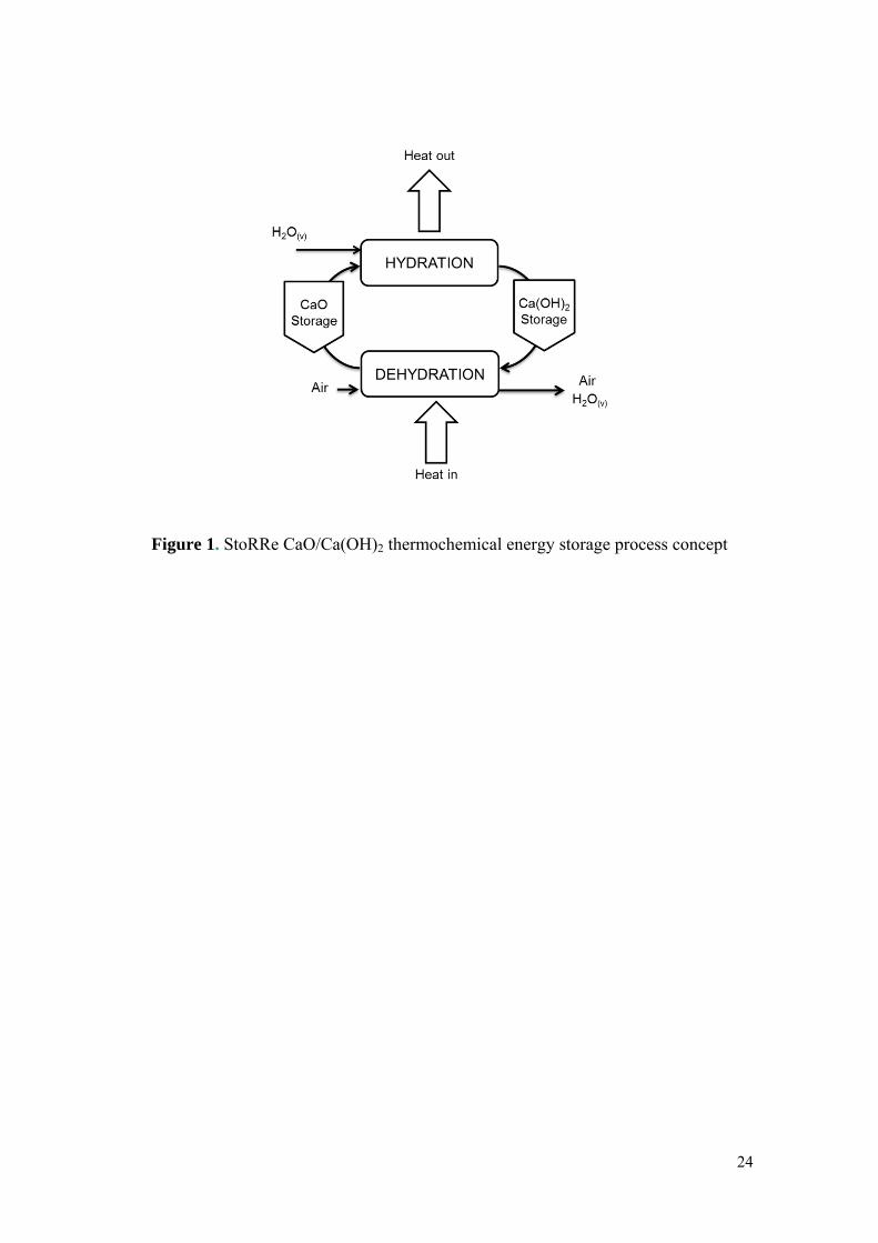
storage systems using the CaO/Ca(OH)2 reversible reaction. The basic process concept
proposed by CEA for this project is represented in Figure 1. In this process, in-coming
heat (from the solar field or any other heat source) is used to dehydrate the Ca(OH)2 that
decomposes into CaO (which is then stored) and steam. A small fraction of air may be
used as fluidizing gas, although the steam produced during the dehydration of the
incoming solid flow could be sufficient to sustain most of the fluidization of the solids.
4
During the hydration stage, useful heat is released in the reactor when the CaO is re-
hydrated by the reaction with the steam (which also acts as fluidizing gas).
An essential part of the design of the thermochemical energy storage system in Figure 1
is the intrinsic reaction kinetics of the CaO hydration and Ca(OH)2 dehydration under
realistic operating conditions (reaction atmospheres and temperatures). Although some
works have investigated direct hydration with liquid water 17-19, hydration must be
carried out with steam because otherwise the efficiency of the energy storage is severely
reduced (“Heat out” arrow in Figure 1): the hydration enthalpy decreases from - 104 to -
62kJ/mol in standard conditions when liquid water is used as a reactant instead of
steam.
Although CaO hydration/dehydration reactions have been previously recognized as a
suitable thermochemical energy storage system, only a few works have focused on the
experimental evaluation of the kinetics of these reactions 18-27 and in most cases the
operating conditions do not match the requirements of a storage system such as that
described in Figure 1.
A recent work by Schaube et al.20 evaluated the hydration and dehydration reaction
kinetics at high partial steam pressure (up to 95.6kPa) over a large number of
hydration-dehydration cycles and their material did not display any significant
degradation up to 100 cycles. They used different empirical kinetic models for each
reaction step depending on the operation temperature during hydration and depending
on whether the dehydration conversion was higher or lower than 0.2. Lin et al. and
Wang et al.21-23 also recently evaluated the kinetics of the CaO hydration/Ca(OH)2
decomposition at high temperature (550-710ºC) and high partial steam pressure (0.67-
2.33MPa for hydration and a total pressure of 1-3.5MPa) over several cycles. However,
5
the temperature and pressure values at which the reaction kinetics were evaluated in
these works are outside the range (very high pressures) of interest for a process aimed at
fluidized bed technology operating at atmospheric pressure as in Figure 1. Irabien et
al.24 obtained a kinetic model for the dehydration of calcium oxide in the range of
temperatures of 330-450ºC using the random pore model and proposed a pseudo-
homogeneous kinetic model to describe the behavior of calcium hydroxide during the
dehydration process. However, they reported that with their experimental system the
influence of external mass transfer and particle diffusion could not be easily avoided.
Hydration kinetics under liquid water 18, 19 instead of steam as proposed by Irabien et al.
in another work, are not applicable to thermochemical energy storage processes for the
reasons mentioned above. Galwey et al.25 studied the dehydration reaction in a glass
vacuum apparatus coupled to a TG analyzer using 10mg and 28mg samples of Ca(OH)2.
Their study showed that dehydration rates were affected by the dispersion of the
reactant particles inside the reaction tube in an ideal fixed bed. They found that a first
order rate equation provided the most satisfactory fit to the data. Over successive
dehydration/rehydration cycles they observed that reaction rates increased in both
directions as a result of crystallite disintegration, with the reaction proceeding more
rapidly for smaller particles. Matsuda et al.26 studied the reversible Ca(OH)2/CaO
reaction for energy storage applications at reaction temperatures between 83 and 450ºC
and steam concentrations between 1.5 to 15.7%vol. and proposed a first order reaction
for both reactions. However, the partial steam pressure applied in their work was
substantially lower than what would be used in systems such as that of Figure 1, where
a maximum steam content in the gases is targeted in order to minimize the air flow
requirement and hence, the cross-sectional area of the reactors for a given superficial
gas velocity.

6
In view of the limited research work carried out on CaO hydration/dehydration reactions
kinetics for thermochemical energy storage applications with particle materials suitable
for fluidized bed reactors, the aim of this work is to study the intrinsic kinetics of the
hydration and dehydration reactions of CaO in highly concentrated atmospheres of
steam. The kinetics information obtained and the model used to interpret the
experimental results will be a valuable tool for designing fluidized bed reactors for use
in energy storage systems such as that represented in Figure 1. The materials and
experimental conditions for the kinetic experimental tests have been selected with this
aim in mind.
Experimental Section
The hydration and dehydration reactions of CaO particles have been experimentally
studied in a thermo-gravimetric analyzer (TG) especially designed for long multicycle
gas-solid reactions, and adapted to operate with pure steam or air-steam mixtures, as
described below.
The TG apparatus consists of a quartz tube (2.5×10⁻²m o.d.) placed inside a two-zone
furnace capable of working at temperatures of up to 1000ºC and at different
temperatures in each furnace zone. For the tests described in this work, the sample
holder was located in the upper furnace position, allowing the bottom part of the oven to
be used for preheating and mixing the steam and air mixture before they reached the
sample. During all the experiments, the sample weight, temperature and flows were
continuously recorded on a computer.
For each run in the TG, around 3 mg of sample was introduced into the sample holder
and the total gas flow was set to 7.3×10⁻⁶m3/s (STP) which corresponds to a superficial
gas velocity of 0.05m/s around the sample at 550ºC. This avoids undesired diffusional

7
effects around the sample when a high amount of mass and/or low gas velocities are
used. In these conditions the kinetics observed during the experiments will be
representative of the intrinsic characteristics of hydration/dehydration reactions and not
of the particular characteristics of the experimental set up (shape and size of the plate,
reacting gas velocity, location of thermocouple etc.) or the sample (i.e. sample mass).
The high gas velocity, required to derive relevant kinetic parameters at particle level,
caused some disturbances in the weight readings in the TG head, that need to be
calibrated. To determine the additional disturbances in the weight readings when
changing from hydration to dehydration, blank experiments for each different set of
conditions were performed using an empty sample holder and an inert material. After
correcting the data obtained from the blank tests, plots of conversion vs. time for each
cycle were made from the weight losses and gains recorded. At the end of each run, the
samples were weighed in a different precision balance to check the accuracy of the
weight measurements made during the experiments.
The TG system used in this work is depicted in Figure 2. The bottles on the left-hand
side of the figure contain one liter of distilled liquid water at ambient temperature and
pressurized to 500kPa by means of N2. Two parallel lines of water were installed in
order allow a continuous supply of water to the system. After the water bottles, a
Bronkhorst liquid mass flow controller provides a precise water mass flow of between
1.4×10⁻³ and 2.8×10⁻²g/s. To vaporize the liquid water, the pipeline is heated by means
of a heating tape whose temperature (the same as the oven temperature to avoid changes
in the steam flow between the pipe line and the TG) is adjusted by means of a
temperature controller. This heating zone is located at a sufficient distance from the
mass flow controller (0.2m) to ensure that the high temperature does not interfere with
the controller. To guarantee complete, uniform and stable vaporization in the first

8
heating zone, several filters are situated along the pipe line to ensure a uniform
distribution of the water. After the filters, a precision needle valve creates a damping
effect when combined with the water bottles pressurized to 500kPa. This ensures that a
continuous and steady flow of steam is provided to the TG.
A three-position pneumatic valve allows a continuous flow of steam during the change
from steam (or mixtures of air and steam) to air conditions. The valve inlet is connected
to the heated steam generation pipe. One of the valve outlets is connected to the TG
apparatus inlet pipe line (also heated up) and the other one to a cold pipe where steam is
condensed before it leaves the system. During the pure steam or air-steam mixture step,
the pneumatic valve inlet is connected to the TG and during the pure air step the steam
leaves the system through the cold pipe.
Steam and/or synthetic air are fed to the bottom of the quartz tube enclosed by the oven.
Up to the oven, the pipe connected to the quartz tube is also heated up. The low furnace
zone (below the sample basket) is heated up to the lower experimental temperature. The
temperature in the upper zone was selected as the reaction temperature for the hydration
and dehydration conditions respectively. To minimize errors arising from the
temperature profiles in the oven, the sample temperature is controlled by a
thermocouple located just a couple of millimeters below the sample pan. To allow the
gas to leave through the orifice at the top of the quartz tube, a continuous air purge is
passed through the balance head (3.3×10⁻⁵m3/s (STP)). The top of the quartz tube is also
heated up to 50ºC by means of a thermal cord.
For the hydration/dehydration cycling experiments, CaO was obtained from two natural
limestones with different compositions, Compostilla (89% CaCO3) and Imeco (98.7%
CaCO3) that were calcined at 800ºC in pure air (7.3×10⁻⁶m3/s (STP)) for 10 min before
9
each experiment. A series of tests were carried out to determine the effect of the particle
size on the hydration/dehydration rates. For this purpose four particle size cuts were
tested 100-200μm, 400-600μm, 800μm-1mm and 1-2mm. Since the main objective of
this work is to derive intrinsic hydration/dehydration kinetics, the 100-200μm particle
size was used in most tests. The hydration and dehydration reactions were studied over
a temperature range of 400 to 560ºC and several partial steam pressures (PH2O) were
tested ranging from pure steam to pure air at a total pressure of 100kPa.
Results and Discussion
Most of the experiments carried out to derive kinetic data for the hydration and
dehydration reactions considered in this work have been conducted in conditions
relatively close to equilibrium. This is because the design of energy storage systems
used to exploit these reversible reactions aims to operate at the highest possible
temperature in the case of hydration (to maximize the efficiency in the transformation to
useful energy of the “Heat out” arrow of Figure 1). This will lead to operation
conditions close to the equilibrium for hydration (at atmospheric pressure, this means
temperatures in the range of 450 to 500ºC in steam volume fractions close to one). In
contrast, for the dehydration step, the design aims to operate at the lowest possible
temperature (to minimize the heat requirements for preheating the solids and the
dehydration reaction). In principle, this can be achieved by two means: using a large
flow of purge gas (air or equivalent) in order to operate the dehydrator under low
volume fractions of steam or using dehydration temperatures as close as possible over
the equilibrium. The first approach requires a larger flow of air in Figure 1, which will
increase the energy required to heat up the gas and the gas velocities in the fluidized bed
dehydrator reactor. The second approach (minimum or no air requirements) will require
operation at temperatures close to the equilibrium temperature (between 500 to 550ºC).
10
These design decisions (in particular the one affecting the flow of air to the dehydrator)
will have large implications for the required reactor design (bubbling reactors vs.
circulating fluidized bed reactors) but detailed analysis of these reactors is beyond the
scope of this paper. What is clear from the previous discussion is that in all cases, both
the hydration and dehydration reactions will be conducted in conditions as close as
possible (kinetics allowing) to the equilibrium of H2O(v) in CaO.
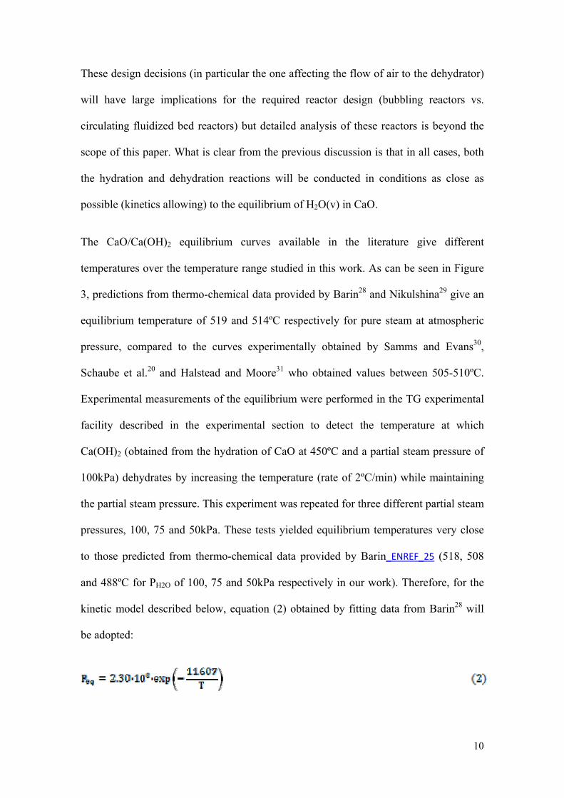
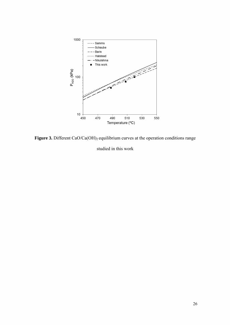
The CaO/Ca(OH)2 equilibrium curves available in the literature give different
temperatures over the temperature range studied in this work. As can be seen in Figure
3, predictions from thermo-chemical data provided by Barin28 and Nikulshina29 give an
equilibrium temperature of 519 and 514ºC respectively for pure steam at atmospheric
pressure, compared to the curves experimentally obtained by Samms and Evans30,
Schaube et al.20 and Halstead and Moore31 who obtained values between 505-510ºC.
Experimental measurements of the equilibrium were performed in the TG experimental
facility described in the experimental section to detect the temperature at which
Ca(OH)2 (obtained from the hydration of CaO at 450ºC and a partial steam pressure of
100kPa) dehydrates by increasing the temperature (rate of 2ºC/min) while maintaining
the partial steam pressure. This experiment was repeated for three different partial steam
pressures, 100, 75 and 50kPa. These tests yielded equilibrium temperatures very close
to those predicted from thermo-chemical data provided by Barin_ENREF_25 (518, 508
and 488ºC for PH2O of 100, 75 and 50kPa respectively in our work). Therefore, for the
kinetic model described below, equation (2) obtained by fitting data from Barin28 will
be adopted:
11
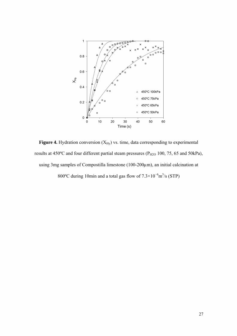
Experimental curves of hydration conversion (XHy) vs. time were obtained for CaO
samples of different particle size (diameter ranges between 0.1 and 2mm), at various
volume fractions of steam (from 0.5 to 1) and temperatures (between 400 and 500ºC).
Figure 4 shows the experimental results for the CaO hydration conversion at different
partial steam pressures (100, 75, 65 and 50kPa). The results shown here correspond to
the calcined Compostilla limestone (89% CaCO3). However, tests were also performed
using Imeco (98.7% CaCO3) and similar results were obtained for both samples.
As can be seen in Figure 4, after a fast initial kinetic regime there is a smooth change in
the reaction rate to a slower reaction regime. The experimental results show that
complete conversion can be achieved within 20-30s under high partial steam pressures
(i.e. 100 or 75kPa) which are the most favorable hydration conditions for these
experiments. The fluctuations in hydration conversion between 0.85-1 are attributed to
inherent experimental measurement errors, as no-similar trend has been observed in
other experiments. These experimental results reveal a much faster hydration reaction
than expected when compared to the kinetic results described by other authors in the
state of the art 20, 21, 26. As pointed out in the experimental section, special care was
taken to minimize diffusional resistances related to the experimental setup, gas solid
flows or sample mass. The absence of these resistances during the kinetic reaction test
could explain why the rate of the hydration reactions in Figure 4 is somewhat higher
than expected.
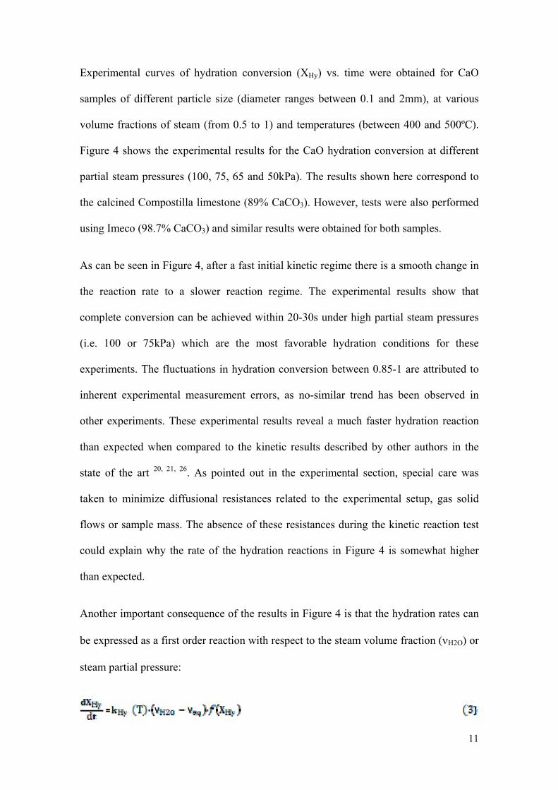
Another important consequence of the results in Figure 4 is that the hydration rates can
be expressed as a first order reaction with respect to the steam volume fraction (νH2O) or
steam partial pressure:

12
This dependency has been observed in other series of experiments similar to those of
Figure 4 and is quite common in reversible decomposition reactions 32.
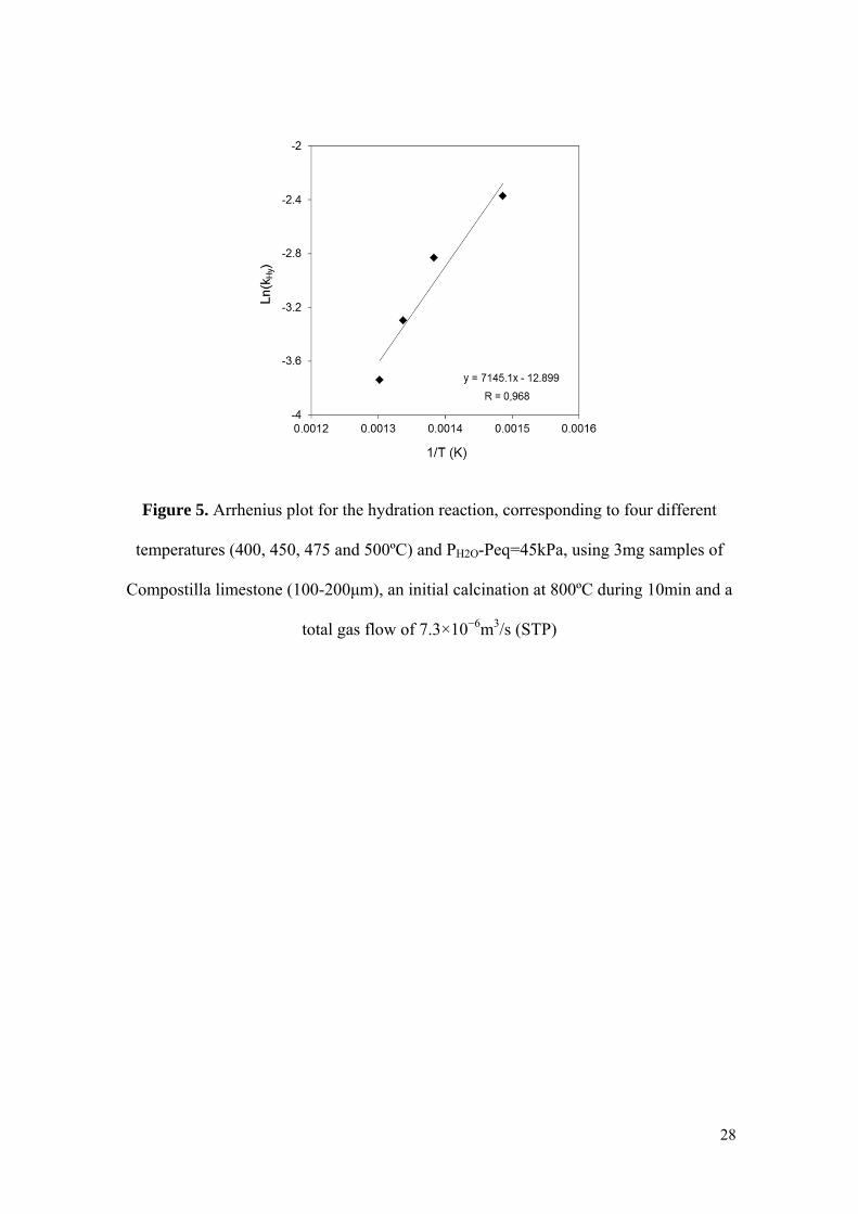
The temperature dependence of the kinetic constant kHy(T) was estimated by fitting
individual values of kHy data at different temperatures, as shown in Figure 5. The
activation energy for the CaO hydration derived from these results is
EHy=(59.4±0.5)×103J/mol and the pre-exponential factor is AHy=(2.5±0.2)×10-6 1/s. The
activation energy value obtained is consistent with the range of values reported in the
literature20 between 58.2×10³ and 83.5×10³J/mol. _ENREF_15
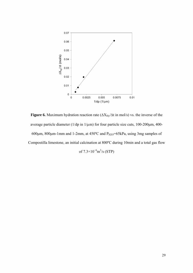
Finally, experiments with different particle sizes were carried out to identify the
reaction surface available during hydration and the overall reaction model at particle
level. Two extreme reaction models were considered depending on whether the reaction
occurred throughout the entire particle at the same time -a pseudo-homogenous model-
or whether the reaction occurred on the particle surface -shrinking core model-33.
Figure 6 represents the results of these experiments in terms of maximum reaction rate
(experimental ΔXHy/Δt) vs. the inverse of the average particle diameter (dp). The same
operation conditions were maintained for each particle size interval. As can be seen, the
results fit to a straight line, which points to a shrinking core model in which the
chemical reaction is the controlling stage (at least during the first fast stage of the
hydration reaction). Therefore, assuming spherical particles, equation (4) can be applied
to calculate the CaO hydration conversion as a function of time as follows:
and in integrated form:
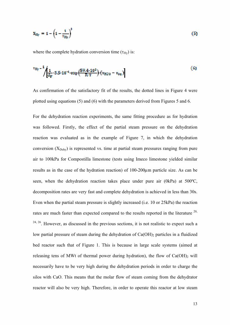
13
where the complete hydration conversion time (τHy) is:
As confirmation of the satisfactory fit of the results, the dotted lines in Figure 4 were
plotted using equations (5) and (6) with the parameters derived from Figures 5 and 6.
For the dehydration reaction experiments, the same fitting procedure as for hydration
was followed. Firstly, the effect of the partial steam pressure on the dehydration
reaction was evaluated as in the example of Figure 7, in which the dehydration
conversion (XDehy) is represented vs. time at partial steam pressures ranging from pure
air to 100kPa for Compostilla limestone (tests using Imeco limestone yielded similar
results as in the case of the hydration reaction) of 100-200μm particle size. As can be
seen, when the dehydration reaction takes place under pure air (0kPa) at 500ºC,
decomposition rates are very fast and complete dehydration is achieved in less than 30s.
Even when the partial steam pressure is slightly increased (i.e. 10 or 25kPa) the reaction
rates are much faster than expected compared to the results reported in the literature 20,
24, 26. However, as discussed in the previous sections, it is not realistic to expect such a
low partial pressure of steam during the dehydration of Ca(OH)2 particles in a fluidized
bed reactor such that of Figure 1. This is because in large scale systems (aimed at
releasing tens of MWt of thermal power during hydration), the flow of Ca(OH)2 will
necessarily have to be very high during the dehydration periods in order to charge the
silos with CaO. This means that the molar flow of steam coming from the dehydrator
reactor will also be very high. Therefore, in order to operate this reactor at low steam
14
partial pressures, (for example PH2O=10kPa) it will be necessary to use an air flow 10
times higher than the steam flow coming out of the reactor. This will entail large energy
requirements and additional equipment for preheating the air as well as unacceptable
large reactor cross-sections and/or superficial gas velocities. Therefore, the most useful
kinetic information for dehydration must be obtained at higher partial pressures of
steam.
As can be seen in Figure 7, as the partial steam pressure increases and the operation
conditions approach equilibrium (for a partial steam pressure of 50kPa) the reaction
rates slow down considerably. On the other hand, as discussed above, future reactors
may have to operate for dehydration under pure steam at the expense of higher reactor
temperatures. In this example, this is represented by a single curve at 560ºC (see Figure
7), which indicates that Ca(OH)2 dehydrates completely within only 10s under these
conditions, far from the equilibrium due to the higher operating temperature.
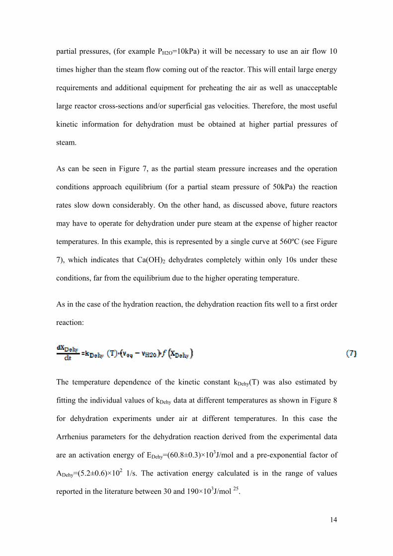
As in the case of the hydration reaction, the dehydration reaction fits well to a first order
reaction:
The temperature dependence of the kinetic constant kDehy(T) was also estimated by
fitting the individual values of kDehy data at different temperatures as shown in Figure 8
for dehydration experiments under air at different temperatures. In this case the
Arrhenius parameters for the dehydration reaction derived from the experimental data
are an activation energy of EDehy=(60.8±0.3)×103J/mol and a pre-exponential factor of
ADehy=(5.2±0.6)×102 1/s. The activation energy calculated is in the range of values
reported in the literature between 30 and 190×103J/mol 25.
15
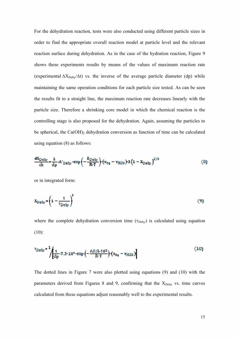
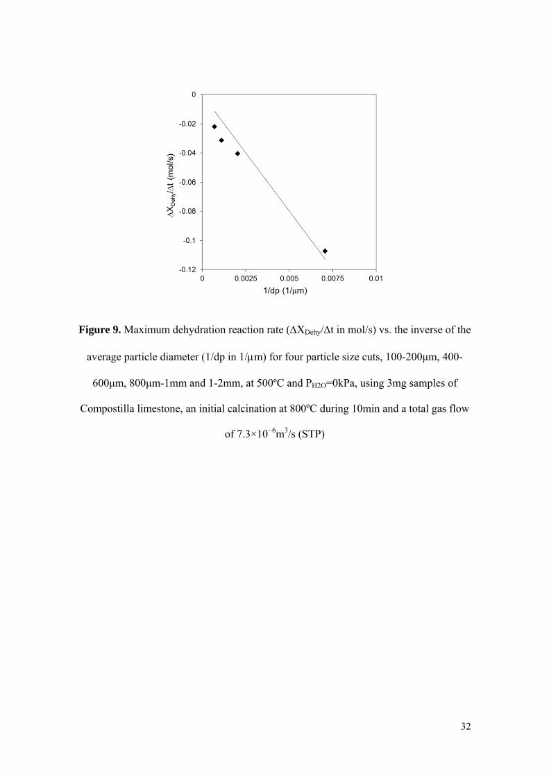
For the dehydration reaction, tests were also conducted using different particle sizes in
order to find the appropriate overall reaction model at particle level and the relevant
reaction surface during dehydration. As in the case of the hydration reaction, Figure 9
shows these experiments results by means of the values of maximum reaction rate
(experimental ΔXDehy/Δt) vs. the inverse of the average particle diameter (dp) while
maintaining the same operation conditions for each particle size tested. As can be seen
the results fit to a straight line, the maximum reaction rate decreases linearly with the
particle size. Therefore a shrinking core model in which the chemical reaction is the
controlling stage is also proposed for the dehydration. Again, assuming the particles to
be spherical, the Ca(OH)2 dehydration conversion as function of time can be calculated
using equation (8) as follows:
or in integrated form:
where the complete dehydration conversion time (τDehy) is calculated using equation
(10):
The dotted lines in Figure 7 were also plotted using equations (9) and (10) with the
parameters derived from Figures 8 and 9, confirming that the XDehy vs. time curves
calculated from these equations adjust reasonably well to the experimental results.

16
Finally, several experiments were conducted in which individual samples of different
particle size were subjected to several cycles of hydration and dehydration.
Figure 10 shows the hydration conversion (XHy) vs. the number of cycles of hydration-
dehydration (N) for experiments carried out with hydration during 300s at 450ºC and
PH2O=65kPa followed by complete dehydration at 500ºC in pure air. As can be seen, for
the smaller particle size intervals (100-200μm and even for 400-600μm) almost total
hydration is achieved in all the cycles after 300s. Further tests up to 32 cycles with
calcined natural limestone of size 100-200μm showed no decay in
hydration/dehydration conversion, confirming the reversibility of the reaction couple (in
agreement with the experimental results reported by Ervin14 and Rosemary et al.16 up to
211 and 1171 cycles respectively). However, as the particle size increases (800μm-1mm
and 1-2mm) no complete hydration conversion is achieved after 300s during the first
few hydration cycles. This result is fully consistent with the shrinking core model
described above, as the available surface is inversely proportional to the particle size
(Figure 6) and 300s is too short time to achieve higher conversions than those reported
in Figure 10. However, a clear trend towards increasing conversion with the number of
cycles is observed, which may be related to physical damage and the breakage of the
particle porous structure with the consecutive hydrations and dehydrations, confirmed
by visual observation of the particles after these tests. The particle breaking mechanism
facilitates the diffusion of steam through the particle cracks and makes more CaO
surface available for reaction with steam.
When the largest particle size cuts were subjected to higher partial steam pressure
during hydration (>75kPa) at a temperature of 450ºC, the particles were completely
broken down into fine powders after the first or second cycle and complete conversion
were achieved in all the cycles in just a few seconds as were observed with the 100-
17
200μm size cut. These experiments at higher pressure gradients during hydration show
that the use of high partial steam pressure and the fast hydration rate are
counterproductive because the mechanical resistance diminishes as the hydration rate
increases. The particle breakage observed indicates that there is scope for optimizing
hydration conditions in order to minimize material losses. It will probably be necessary
to use CaO-supported or pretreated particles with better mechanical properties for
fluidization. It is beyond the scope of the present work to analyze these materials.
However the experimental and modeling results presented in this work to describe the
kinetics of hydration and dehydration of CaO/Ca(OH)2 should serve as a valuable aid
for future designs of reactor concepts suitable for exploiting the energy storage potential
of the CaO/Ca(OH)2 hydration and dehydration reactions.
Conclusions
In this work the CaO hydration and Ca(OH)2 dehydration reactions have been studied in
the 400 to 560ºC temperature range and at partial steam pressures from 0 to 100kPa in a
thermo-gravimetric analyzer (TG) operating under differential conditions. These
reaction conditions may be relevant to future designs of large scale thermochemical
energy storage systems involving fluidized bed reactors for hydration and dehydration.
The shrinking core model has been used to fit both the experimental hydration and
dehydration conversion curves. The CaO particles react following a chemically
controlled first order reaction, displaying activation energies of 59.4×10³ and
60.8×10³J/mol and pre-exponential factors of 2.5×10⁻⁶ and 5.2×10² 1/s (for a particle
size of 100-200μm) for hydration and dehydration reactions respectively. The reaction
rates observed in all cases are considerably higher than the few so far reported in the
literature under comparable conditions. This may indicate the presence of misleading
18
resistances to the progression of the reactions in previous studies. In this work, particle
breakage has been detected when working with larger CaO particles, which indicates
that it might be necessary to use CaO-supported particles with better mechanical
properties for fluidization. However, since the reaction rates observed under reasonable
reaction conditions were much faster than expected (complete hydration or dehydration
was reached in less than 60s in most cases), it can be concluded that there is still scope
for developing suitable materials and fluidized bed reactors to perform CaO/Ca(OH)2
hydration and dehydration reactions in future energy storage systems .
Acknowledgment
The authors acknowledge the financial support provided by the European Commission
under the 7th Framework Program (StoRRe Project GA 282677). Y.A. Criado thanks the
Government of the Principality of Asturias for a Ph.D. fellowship (Severo Ochoa
Program).
Nomenclature
A pre-exponential factor for a particle size cut of 100-200μm, 1/s
A’ pre-exponential factor, μm /s
dp average particle size, μm
E activation energy, J/mol
k kinetic constant, 1/s
N number of hydration-dehydration cycles
Peq equilibrium pressure, kPa

19
PH2O partial steam pressure, kPa
R universal gas constant, J/mol K
T temperature, K
t time, s
X conversion, mol H2O/ mol CaO
ΔH reaction enthalpy, kJ/mol at 298K
νΗ2Ο steam volume fraction
νeq equilibrium volume fraction
τ complete conversion time, s
Subscripts
Hy hydration reaction
Dehy dehydration reaction
References
(1) IPCC Special Report on Renewable Energy Sources and Climate Change
Mitigation; Cambridge University Press: United Kingdom and New York, NY, USA,
2011.
20
(2) Hou, Y.; Vidu, R.; Stroeve, P. Solar Energy Storage Methods. Ind. Eng. Chem. Res.
2011, 50, 8954-8964.
(3) Kuravi, S.; Trahan, J.; Goswami, D. Y.; Rahman, M. M.; Stefanakos, E. K. Thermal
energy storage technologies and systems for concentrating solar power plants. Prog.
Energy Combust. Sci. 2013, 39, 285-319.
(4) Gil, A.; Medrano, M.; Martorell, I.; Lázaro, A.; Dolado, P.; Zalba, B.; Cabeza, L. F.
State of the art on high temperature thermal energy storage for power generation. Part
1—Concepts, materials and modellization. Renewable Sustainable Energy Rev. 2010,
14, 31-55.
(5) Liu, M.; Saman, W.; Bruno, F. Review on storage materials and thermal
performance enhancement techniques for high temperature phase change thermal
storage systems. Renewable Sustainable Energy Rev. 2012, 16, 2118-2132.
(6) Cot-Gores, J.; Castell, A.; Cabeza, L. F. Thermochemical energy storage and
conversion: A-state-of-the-art review of the experimental research under practical
conditions. Renewable Sustainable Energy Rev. 2012, 16, 5207-5224.
(7) Wentworth, W. E.; Chen, E. Simple thermal decomposition reactions for storage of
solar thermal energy. Sol. Energy 1976, 18, 205-214.
(8) Fujii, I.; Tsuchiya, K.; Higano, M.; Yamada, J. Studies of an energy storage system
by use of the reversible chemical reaction: CaO + H2O Ca(OH)2. Sol. Energy 1985,
34, 367-377.
21
(9) Kanzawa, A.; Arai, Y. Thermal energy storage by the chemical reaction
augmentation of heat transfer and thermal decomposition in the CaO/Ca(OH)2 powder.
Sol. Energy 1981, 27, 289-294.
(10) Schaube, F.; Kohzer, A.; Schütz, J.; Wörner, A.; Müller-Steinhagen, H. De- and
rehydration of Ca(OH)2 in a reactor with direct heat transfer for thermo-chemical heat
storage. Part A: Experimental results. Chem. Eng. Res. Des. 2013, 91, 856-864.
(11) Schaube, F.; Utz, I.; Wörner, A.; Müller-Steinhagen, H. De- and rehydration of
Ca(OH)2 in a reactor with direct heat transfer for thermo-chemical heat storage. Part B:
Validation of model. Chem. Eng. Res. Des. 2013, 91, 865-873.
(12) Schaube, F.; Worner, A.; Tamme, R. High Temperature Thermochemical Heat
Storage for Concentrated Solar Power Using Gas-Solid Reactions. J. Sol. Energy Eng.
2011, 133, 031006.
(13) Schmidt, M.; Szczukowski, C.; Roßkopf, C.; Linder, M.; Wörner, A. Experimental
results of a 10 kW high temperature thermochemical storage reactor based on calcium
hydroxide. Appl. Therm. Eng. 2014, 62, 553-559.
(14) Ervin, G. Solar heat storage using chemical reactions. J. Solid State Chem. 1977,
22, 51-61.
(15) Ervin, G. Method of storing and releasing thermal energy. US 3.973.552, Aug. 10,
1976.
(16) Rosemary, J. K.; Bauerle, G. L.; Springer, T. H. Solar energy storage using
reversible hydration/dehydration of CaO-Ca(OH)2, AIAA Terrestrial Energy Systems
Conference, Orlando, Florida, 1979; 79-0986.
(17) Azpiazu, M. N.; Morquillas, J. M.; Vazquez, A. Heat recovery from a thermal
energy storage based on the Ca(OH)2/CaO cycle. Appl. Therm. Eng. 2003, 23, 733-741.

22
(18) Irabien, A.; Toquero, A.; Ortiz, M. I. Kinetic behaviour of non-isothermal lime
hydration. Chem. Eng. J. 1989, 40, 93-99.
(19) Whitman, W. G.; Davis, G. H. B. The Hydration of Lime. Ind. Eng. Chem. 1926,
18, 118-120.
(20) Schaube, F.; Koch, L.; Wörner, A.; Müller-Steinhagen, H. A thermodynamic and
kinetic study of the de- and rehydration of Ca(OH)2 at high H2O partial pressures for
thermo-chemical heat storage. Thermochim. Acta 2012, 538, 9-20.
(21) Lin, S.; Harada, M.; Suzuki, Y.; Hatano, H. CaO Hydration Rate at High
Temperature ( 1023 K). Energy Fuels 2006, 20, 903-908.
(22) Lin, S.; Wang, Y.; Suzuki, Y. High-Temperature CaO Hydration/Ca(OH)2
Decomposition over a Multitude of Cycles. Energy Fuels 2009, 23, 2855-2861.
(23) Wang, Y.; Lin, S.; Suzuki, Y. Effect of CaO content on hydration rates of Ca-based
sorbents at high temperature. Fuel Process. Technol. 2008, 89, 220-226.
(24) Irabien, A.; Viguri, J. R.; Ortiz, I. Thermal dehydration of calcium hydroxide. 1.
Kinetic model and parameters. Ind. Eng. Chem. Res. 1990, 29, 1599-1606.
(25) Galwey, A. K.; Laverty, G. M. A kinetic and mechanistic study of the
dehydroxylation of calcium hydroxide. Thermochim. Acta 1993, 228, 359-378.
(26) Matsuda, H.; Ishizu, T.; Lee, S. K.; Hasatani, M. Kinetic Study of Ca(OH)2/CaO
Reversible Thermochemical Reaction for Thermal Energy Storage by Means of
Chemical Reaction. Kagaku Kogaku Ronbun. 1985, 11, 542-548.
(27) Fujii, I.; Ishino, M.; Akiyama, S.; Murthy, M. S.; Rajanandam, K. S. Behavior of
Ca(OH)2/CaO pellet under dehydration and hydration. Sol. Energy 1994, 53, 329-341.
23
(28) Barin, I. Thermochemical data of pure substances; VCH Verlagsgesellschaft
Weinheim, Germany; New York, 1989.
(29) Nikulshina, V.; Steinfeld, A. CO2 capture from air via CaO-carbonation using a
solar-driven fluidized bed reactor - Effect of temperature and water vapor concentration.
Chem. Eng. J. 2009, 155, 867-873.
(30) Samms, J. A. C.; Evans, B. E. Thermal dissociation of Ca(OH)2 at elevated
pressures. J. Appl. Chem. 1968, 18, 5-8.
(31) Halstead, P. E.; Moore, A. E. The thermal dissociation of calcium hydroxide. J.
Chem. Soc. 1957, 3873-3875.
(32) Vyazovkin, S.; Burnham, A. K.; Criado, J.M.; Pérez-Maqueda, L.A.; Popescu, C.;
Sbirrazzuoli, N. ICTAC Kinetics Committee recommendations for performing kinetic
computations on thermal analysis data. Thermochim. Acta 2011, 520, 1-19.
(33) Levenspiel, O. Chemical Reaction Engineering; John Wiley & Sons: New York,
1999.
24
Figure 1. StoRRe CaO/Ca(OH)2 thermochemical energy storage process concept

25
Figure 2. Thermo-gravimetric analyzer and steam generation equipment scheme
26
Figure 3. Different CaO/Ca(OH)2 equilibrium curves at the operation conditions range
studied in this work
27
Figure 4. Hydration conversion (XHy) vs. time, data corresponding to experimental
results at 450ºC and four different partial steam pressures (PH2O 100, 75, 65 and 50kPa),
using 3mg samples of Compostilla limestone (100-200μm), an initial calcination at
800ºC during 10min and a total gas flow of 7.3×10⁻⁶m3/s (STP)
28
Figure 5. Arrhenius plot for the hydration reaction, corresponding to four different
temperatures (400, 450, 475 and 500ºC) and PH2O-Peq=45kPa, using 3mg samples of
Compostilla limestone (100-200μm), an initial calcination at 800ºC during 10min and a
total gas flow of 7.3×10⁻⁶m3/s (STP)
29
Figure 6. Maximum hydration reaction rate (ΔXHy/Δt in mol/s) vs. the inverse of the
average particle diameter (1/dp in 1/μm) for four particle size cuts, 100-200μm, 400-
600μm, 800μm-1mm and 1-2mm, at 450ºC and PH2O=65kPa, using 3mg samples of
Compostilla limestone, an initial calcination at 800ºC during 10min and a total gas flow
of 7.3×10⁻⁶m3/s (STP)

30
Figure 7. Dehydration conversion (XDehy) vs. time at 500ºC and four different partial
steam pressures (PH2O 0, 10, 25 and 50kPa), and 560ºC and 100kPa, using 3mg samples
of Compostilla limestone (100-200μm), an initial calcination at 800ºC during 10min
and a total gas flow of 7.3×10⁻⁶m3/s (STP)

31
Figure 8. Arrhenius parameters calculation for dehydration reaction for six different
temperatures (400, 415, 433, 450, 475 and 500ºC) and PH2O =0kPa, using 3mg samples
of Compostilla limestone (100-200μm), an initial calcination at 800ºC during 10min and
a total gas flow of 7.3×10⁻⁶m3/s (STP)
32
Figure 9. Maximum dehydration reaction rate (ΔXDehy/Δt in mol/s) vs. the inverse of the
average particle diameter (1/dp in 1/μm) for four particle size cuts, 100-200μm, 400-
600μm, 800μm-1mm and 1-2mm, at 500ºC and PH2O=0kPa, using 3mg samples of
Compostilla limestone, an initial calcination at 800ºC during 10min and a total gas flow
of 7.3×10⁻⁶m3/s (STP)

33
Figure 10. Hydration conversion after 300s (XHy) vs. the number of hydration –
dehydration cycles (N) for four experiments carried out with different particle size cuts:
100-200μm, 400-600μm, 800μm-1mm and 1-2mm, under hydration at 450ºC and
PH2O=65kPa and dehydration at 500ºC in air, using 3mg samples of Compostilla
limestone, an initial calcination at 800ºC during 10min and a total gas flow of
7.3×10⁻⁶m3/s (STP)