july 2015 - roman manufacturing inc. | resistance welding ... · pdf filejuly 2015 welding...
TRANSCRIPT
PUBLISHED BY THE AMERICAN WELDING SOCIETY TO ADVANCE THE SCIENCE, TECHNOLOGY, AND APPLICATION OF WELDINGAND ALLIED JOINING AND CUTTING PROCESSES WORLDWIDE, INCLUDING BRAZING, SOLDERING, AND THERMAL SPRAYING
JULY 2015
WE
LD
ING
JOU
RN
AL
• VO
LU
ME
94 NU
MB
ER
7 • JULY
2015
Cover July 2015_4/06 Cover 6/11/15 9:46 AM Page C1

Heat generation is the inherent function and benefit of the resistance welding (RW) process. The heat is generated by an electrical current, which is controlled and transmitted by electrical components. As a result, there will be a constant effect mani-fested by a rise in temperature that, without proper cooling, will affect the system’s electrical components. To avoid this scenario, proper elec-trical component sizing and proper water cooling are the best means of protection for resistance welding (RW) transformers and medium frequency, direct current transform-er rectifiers (hereafter referred to as MFDCs) from overtemperature — thereby ensuring safety, quality, and
uptime. While there are many facets to RW machines, the answers to the question posed will focus on ele-ments that are most closely related to protection from overtemperature.
Electrical Component SizingDuring the concept stage for RW
machines, specifications and expec-tations are broad and open ended.
However, two questions must be answered:
1. What are the parts to be welded?
2. How many parts per minute are targeted; what is the produc-tion rate?
From the answers of these two questions, the RW machine de-signer determines the RW process, frame requirements, operator interface, loading and unloading techniques, etc. As requirements are firmed up, mechanical and elec-trical components require selection and sizing — Fig. 1. Mechanical components include force actuator, frame strength requirements, and movable electrode follow-up.
Electrical components that trans-fer energy to the weld require sizing. These electrical components include electrodes, adapters, bussbar, ca-bling, transformer or MFDC, weld-ing control, circuit breakers, fuses, and primary wiring.
Equipment Density Favors Water Cooling
In any chemical, mechanical, or electrical system, the transfer of energy generates byproducts such as vibration, noise, magnetism, and heat. If excess heat is retained within the electrical components, temperatures will exceed limits and cause premature component failure. Because RW transformers or MFDCs are located in extremely
RWMA Q&ABY MARK SIEHLING
Q: What are the best means to protect resistance welding transformers and medium frequency direct current (MFDC) transformer rectifiers from failure due to overtemperature?
WELDING JOURNAL / JULY 2015
Fig. 1 — Proper electrical component sizing paired with proper water cooling provide the best means to protect resistance welding equipment from overheating.
Fig. 2 — Cooling is critical for resistance welding equipment because it is often located in densely populated equipment areas.
dense equipment locations where high production rates for resistance welding are needed, cooling is criti-cal — Fig. 2. To prevent premature failure, excess heat is transferred to air or water. Where marginal or extreme conditions exist, water cooling is the most effective means to keep electrical components with-in rated temperature limits. There-fore, it is important to properly size and cool electrical components to ensure operation within rated tem-perature limits.
Water Cooling SpecificationsCommon water cooling speci-
fications include maximum inlet temperature in degrees (86°F or 30°C), pressure differential in pounds per square inch (lb/in.2) or bars, and especially flow rate, in gallons per minute (gal/min) or liters per minute (L/min). However, the most critical specification and most common failure root cause is lack of adequate flow rate — each RW electrical component requiring water cooling will have a minimum flow rate in its nameplate. Elec-trical component sizing in design stages is complemented by sensors that protect RW transformers and MFDCs from unintended operation above rated temperature limits.
Note: Further detail about water specifications such as pH, resistivi-ty, chloride, solids, etc., are found in
RWMA Bulletin 14, Utility Connec-tion-Water.
SensorsA RW production line, with
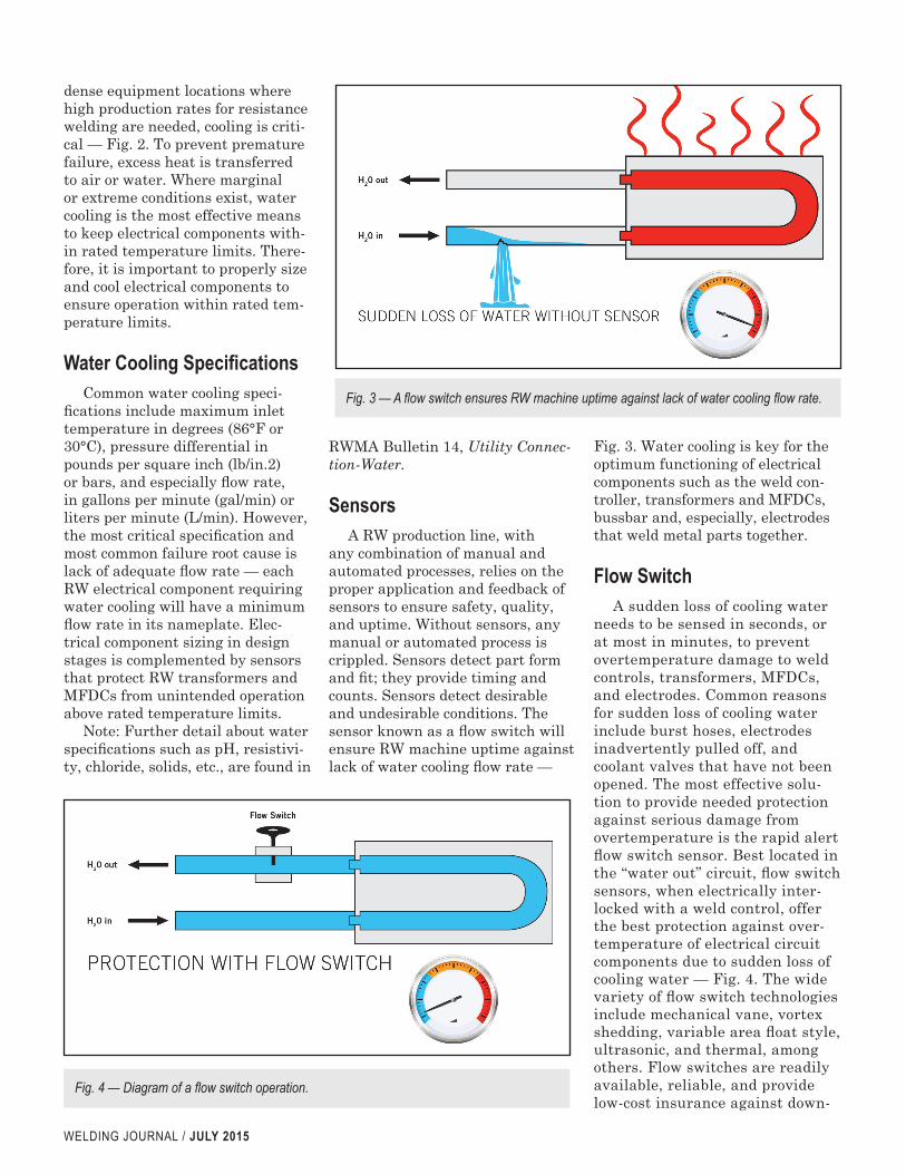
any combination of manual and automated processes, relies on the proper application and feedback of sensors to ensure safety, quality, and uptime. Without sensors, any manual or automated process is crippled. Sensors detect part form and fit; they provide timing and counts. Sensors detect desirable and undesirable conditions. The sensor known as a flow switch will ensure RW machine uptime against lack of water cooling flow rate —
Fig. 3. Water cooling is key for the optimum functioning of electrical components such as the weld con-troller, transformers and MFDCs, bussbar and, especially, electrodes that weld metal parts together.
Flow SwitchA sudden loss of cooling water
needs to be sensed in seconds, or at most in minutes, to prevent overtemperature damage to weld controls, transformers, MFDCs, and electrodes. Common reasons for sudden loss of cooling water include burst hoses, electrodes inadvertently pulled off, and coolant valves that have not been opened. The most effective solu-tion to provide needed protection against serious damage from overtemperature is the rapid alert flow switch sensor. Best located in the “water out” circuit, flow switch sensors, when electrically inter-locked with a weld control, offer the best protection against over-temperature of electrical circuit components due to sudden loss of cooling water — Fig. 4. The wide variety of flow switch technologies include mechanical vane, vortex shedding, variable area float style, ultrasonic, and thermal, among others. Flow switches are readily available, reliable, and provide low-cost insurance against down-
WELDING JOURNAL / JULY 2015
Fig. 3 — A flow switch ensures RW machine uptime against lack of water cooling flow rate.
Fig. 4 — Diagram of a flow switch operation.
time. Consult with your RW trans-former or MFDC supplier for best application information.
Thermo SwitchThermo switches or thermal
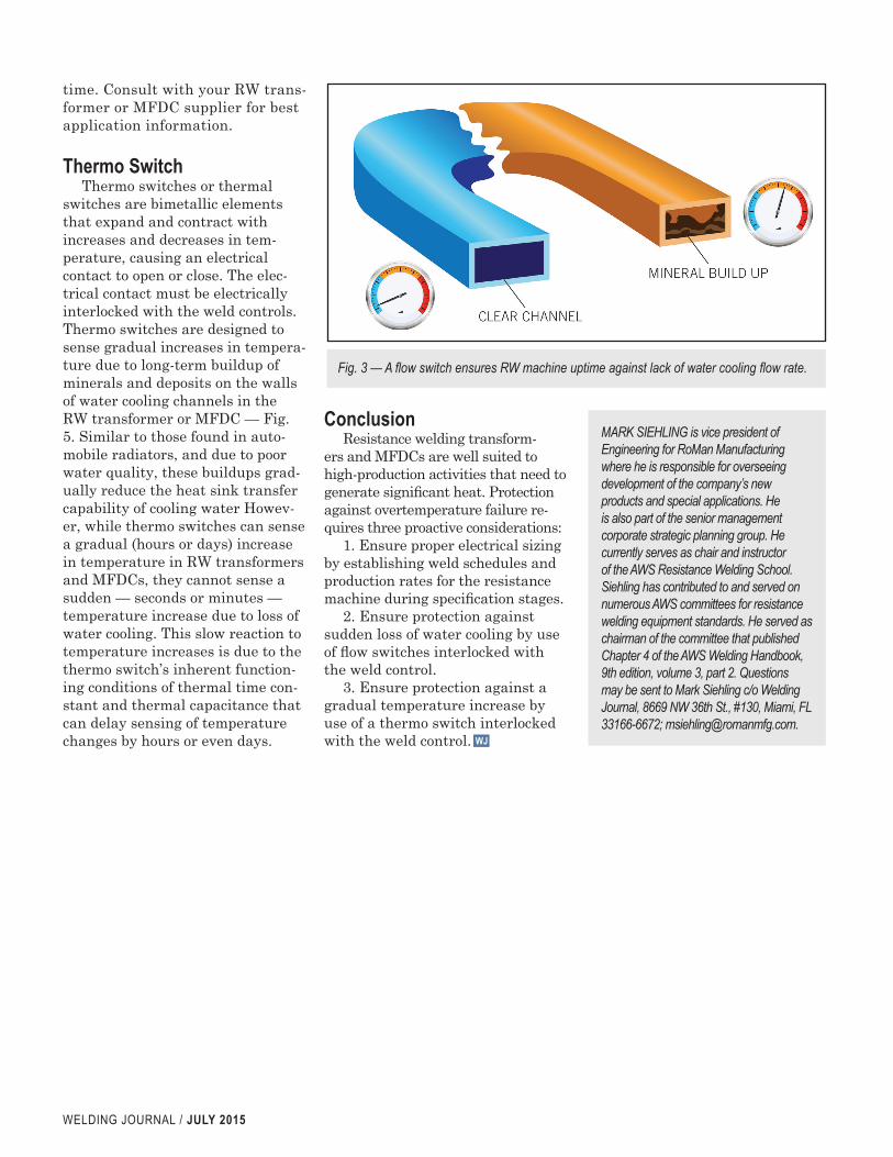
switches are bimetallic elements that expand and contract with increases and decreases in tem-perature, causing an electrical contact to open or close. The elec-trical contact must be electrically interlocked with the weld controls. Thermo switches are designed to sense gradual increases in tempera-ture due to long-term buildup of minerals and deposits on the walls of water cooling channels in the RW transformer or MFDC — Fig. 5. Similar to those found in auto-mobile radiators, and due to poor water quality, these buildups grad-ually reduce the heat sink transfer capability of cooling water Howev-er, while thermo switches can sense a gradual (hours or days) increase in temperature in RW transformers and MFDCs, they cannot sense a sudden — seconds or minutes — temperature increase due to loss of water cooling. This slow reaction to temperature increases is due to the thermo switch’s inherent function-ing conditions of thermal time con-stant and thermal capacitance that can delay sensing of temperature changes by hours or even days.
ConclusionResistance welding transform-
ers and MFDCs are well suited to high-production activities that need to generate significant heat. Protection against overtemperature failure re-quires three proactive considerations:
1. Ensure proper electrical sizing by establishing weld schedules and production rates for the resistance machine during specification stages.
2. Ensure protection against sudden loss of water cooling by use of flow switches interlocked with the weld control.
3. Ensure protection against a gradual temperature increase by use of a thermo switch interlocked with the weld control.
Fig. 3 — A flow switch ensures RW machine uptime against lack of water cooling flow rate.
MARK SIEHLING is vice president of Engineering for RoMan Manufacturing where he is responsible for overseeing development of the company’s new products and special applications. He is also part of the senior management corporate strategic planning group. He currently serves as chair and instructor of the AWS Resistance Welding School. Siehling has contributed to and served on numerous AWS committees for resistance welding equipment standards. He served as chairman of the committee that published Chapter 4 of the AWS Welding Handbook, 9th edition, volume 3, part 2. Questions may be sent to Mark Siehling c/o Welding Journal, 8669 NW 36th St., #130, Miami, FL 33166-6672; [email protected].
WJ
WELDING JOURNAL / JULY 2015