centerline resistance welding product · pdf fileresistance welding product guide resistance...
TRANSCRIPT

RESISTANCE WELDINGPRODUCT GUIDE
RESISTANCE WELDINGPRODUCT GUIDE
(WINDSOR) LIMITED
Version 7.0
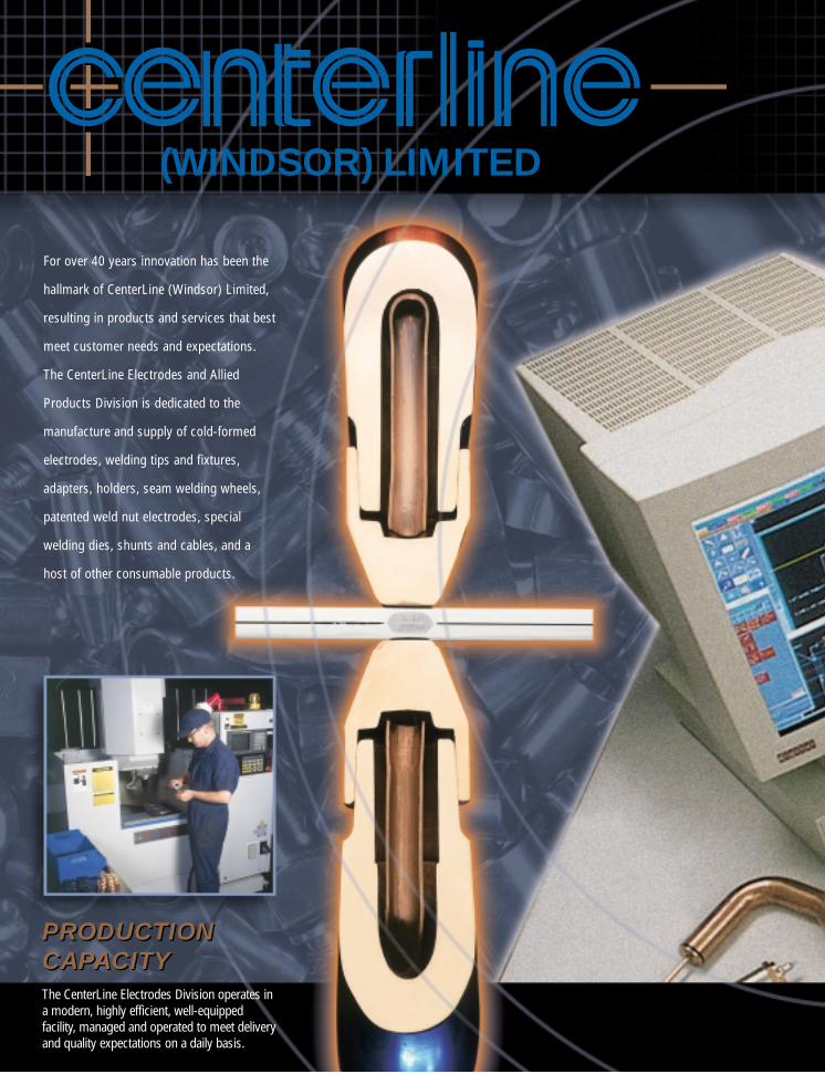
For over 40 years innovation has been the
hallmark of CenterLine (Windsor) Limited,
resulting in products and services that best
meet customer needs and expectations.
The CenterLine Electrodes and Allied
Products Division is dedicated to the
manufacture and supply of cold-formed
electrodes, welding tips and fixtures,
adapters, holders, seam welding wheels,
patented weld nut electrodes, special
welding dies, shunts and cables, and a
host of other consumable products.
PRODUCTIONCAPACITYPRODUCTIONCAPACITYThe CenterLine Electrodes Division operates ina modern, highly efficient, well-equippedfacility, managed and operated to meet deliveryand quality expectations on a daily basis.
(WINDSOR) LIMITED

DESIGNASSISTANCE
MANUFACTURINGEXCELLENCE
INVENTORYSUPPORT
The Complete Joining Company
DESIGNASSISTANCECenterLine prides itself on its ability toquickly react to special electrode andfixture needs. With its wealth of applicationexperience, CenterLine can design andmanufacture components that arespecifically suited to unique applications.
MANUFACTURINGEXCELLENCEIn order to maintain its reputation as aquality supplier, CenterLine continues toinvest in machinery, tooling, and people.This has enabled the company to effectivelyrespond to ever changing industrychallenges.
INVENTORYSUPPORTCenterLine maintains an extensiveinventory to guarantee part supply and tosatisfy emergency needs. CenterLine is atrue partner with its customers, constantlyassisting them in fulfilling theircommitments.

SPECIAL MATERIALS
QUALITY COMMITMENT
PRODUCT DIVERSIFICATION
EXCLUSIVE DEVELOPMENTS
SPECIAL MATERIALS
The variety of materials and coatings used in today’s manufactured components cancreate demanding weld conditions. CenterLine can assist in choosing the rightelectrode material to maximize tip life and effectively weld these components.Available material options such as tungsten faced tips and assorted classes of coppercan resolve many welding problems.
QUALITY COMMITMENT
Because customers depend on CenterLine for quality components, strict adherenceto material and part specification is of primary importance. CenterLine can be reliedupon to consistently supply electrode needs with the quality customers demand andexpect.
PRODUCT DIVERSIFICATION
In addition to offering an abundance of resistance welding consumable products, theCenterLine Electrodes Division is also a manufacturer and supplier of wire weldingcontact tips, insulating materials and bushings, weld gun replacement parts,castings, forgings, shunts, cables, spot welding machine arms and caps, seamwelding wheels and many other production related items. This diversification trulymakes CenterLine a full service supplier.
EXCLUSIVE DEVELOPMENTS
CenterLine continuously introduces new products to satisfy challenges presented by ourcustomers’ requirements.Now, CenterLine has combined its proven nut electrode technology with proven sensingtechnology to create the patented Smart Electrode nut detection system. The SmartElectrode System can help you determine if a weld nut is present and in the correctorientation. This diagnostic device provides a reliable method for enhancing the quality ofthe projection welding process.
(WINDSOR) LIMITED
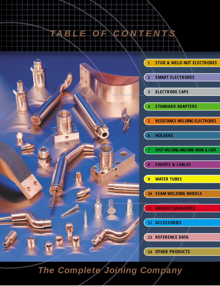
1 STUD & WELD NUT ELECTRODES
The Complete Joining Company
TA B L E O F C O N T E N T S
2 SMART ELECTRODES
3 ELECTRODE CAPS
4 STANDARD ADAPTERS
5 RESISTANCE WELDING ELECTRODES
6 HOLDERS
7 SPOT WELDING MACHINE ARMS & CAPS
8 SHUNTS & CABLES
9 WATER TUBES
10 SEAM WELDING WHEELS
11 GREASE EQUALIZERS
12 ACCESSORIES
13 REFERENCE DATA
14 OTHER PRODUCTS

STUD & WELD NUT ELECTRODES
1-1
CenterLine manufactures a wide variety of stud & nut welding electrodes. The high quality design and assembly provides a number of features and benefits including:
• Accurate on center positioning of pilotless nuts provided automatically.• Insulated pin and sleeve prevents pin arcing in the threads.• Unit converts from welding nuts to studs in seconds by removal of pilot pin and/or welding head.• Used by automotive, mass transit, farm implement, stamping and appliance manufacturers.• Internal water cooling reduces heat build-up.• Minimum maintenance.
Head
Spring
Spring StopOuterSleeve
WaterConnector
O-Ring
Hex HeadScrews Projections Nut
Stamping
Washer
WaterConnector
Air Connector
Base MountStyle
EXPLODED VIEW
SECTION ASSEMBLY VIEW
Pin
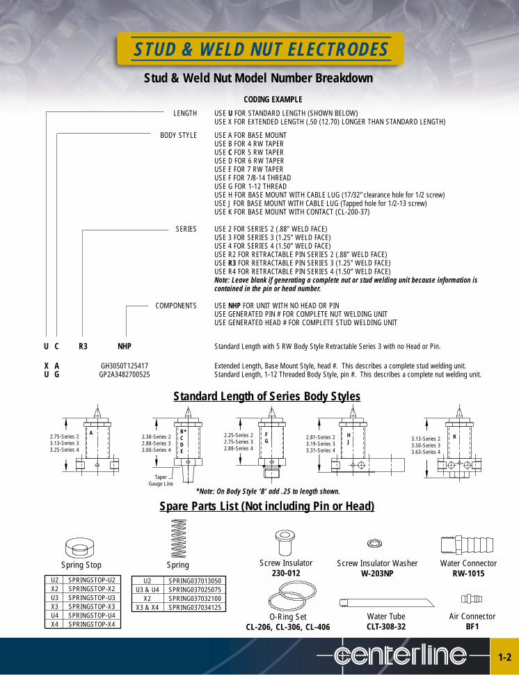
STUD & WELD NUT ELECTRODESStud & Weld Nut Model Number Breakdown
1-2
CODING EXAMPLE
LENGTH USE U FOR STANDARD LENGTH (SHOWN BELOW)USE X FOR EXTENDED LENGTH (.50 (12.70) LONGER THAN STANDARD LENGTH)
BODY STYLE USE A FOR BASE MOUNTUSE B FOR 4 RW TAPERUSE C FOR 5 RW TAPERUSE D FOR 6 RW TAPERUSE E FOR 7 RW TAPERUSE F FOR 7/8-14 THREADUSE G FOR 1-12 THREADUSE H FOR BASE MOUNT WITH CABLE LUG (17/32" clearance hole for 1/2 screw)USE J FOR BASE MOUNT WITH CABLE LUG (Tapped hole for 1/2-13 screw)USE K FOR BASE MOUNT WITH CONTACT (CL-200-37)
SERIES USE 2 FOR SERIES 2 (.88” WELD FACE)USE 3 FOR SERIES 3 (1.25” WELD FACE)USE 4 FOR SERIES 4 (1.50” WELD FACE)USE R2 FOR RETRACTABLE PIN SERIES 2 (.88” WELD FACE)USE R3 FOR RETRACTABLE PIN SERIES 3 (1.25” WELD FACE)USE R4 FOR RETRACTABLE PIN SERIES 4 (1.50” WELD FACE)Note: Leave blank if generating a complete nut or stud welding unit because information iscontained in the pin or head number.
COMPONENTS USE NHP FOR UNIT WITH NO HEAD OR PINUSE GENERATED PIN # FOR COMPLETE NUT WELDING UNITUSE GENERATED HEAD # FOR COMPLETE STUD WELDING UNIT
U C R3 NHP Standard Length with 5 RW Body Style Retractable Series 3 with no Head or Pin.
X A GH3050T125417 Extended Length, Base Mount Style, head #. This describes a complete stud welding unit. U G GP2A3482700525 Standard Length, 1-12 Threaded Body Style, pin #. This describes a complete nut welding unit.
Standard Length of Series Body Styles
Spare Parts List (Not including Pin or Head)
Screw Insulator 230-012
Water ConnectorRW-1015
Air ConnectorBF1
Spring Stop Spring
Water TubeCLT-308-32
U2 SPRING037013050U3 & U4 SPRING037025075
X2 SPRING037032100X3 & X4 SPRING037034125
U2 SPRINGSTOP-U2X2 SPRINGSTOP-X2U3 SPRINGSTOP-U3X3 SPRINGSTOP-X3U4 SPRINGSTOP-U4X4 SPRINGSTOP-X4
O-Ring SetCL-206, CL-306, CL-406
Screw Insulator WasherW-203NP
2.75-Series 23.13-Series 33.25-Series 4
2.38-Series 22.88-Series 33.00-Series 4
Taper Gauge Line
2.25-Series 22.75-Series 32.88-Series 4
2.81-Series 23.19-Series 33.31-Series 4
3.13-Series 23.50-Series 33.63-Series 4
HJ
KFG
BCDE
A *
*Note: On Body Style ‘B’ add .25 to length shown.

STUD & WELD NUT ELECTRODES
1-3
Manual Load Weld Nut Pins
Example GP 2 A 348 270 05 25Breakdown Pin Type Series Nose Type Hole in Stamping -.005” Hole in Nut -.005” Stamping Thickness Nut Thickness
Number (3 Dec.) - see note below (3 Dec.) - see note below (2 Dec.) (2 Dec.)
NOTE: For B & C style pins, the “Hole in Stamping” value is the “Hole in Nut” value (i.e. GP2B2702700525)Part Number
Generate Your Own Number (Total 14 Characters)
PinType DescriptionGP Stainless Steel Pin, Supported by spring and/or airCP Coated, D2 Steel Pin, Supported by spring and/or airRP Retractable, Stainless Steel Pin, Movement controlled by Air Pressure only, Special Application please contact CenterLineKP Coated Retractable, D2 Steel Pin, Movement controlled by Air Pressure only, Special Application please contact CenterLine
Series Thread Size Weld Face Diameter Maximum Hole in Head* Head Height2 5/8-18 7/8 Standard 0.427 (10.85) ID 0.5003 7/8-14 1-1/4 Standard 0.642 (16.31) ID 0.5004 1-1/8-12 1-1/2 Standard 0.852 (21.64) ID 0.625
*Special weld nut electrodes are available for larger IDs and areas with clearance restrictions.
Nose Type DescriptionA Preferred when locating nut and stamping, no stamping contact during weld, no hole in upper electrodeB Preferred when locating nut only, no stamping contact, no hole in upper electrodeC Preferred when locating nut only, no stamping contact, no hole in upper electrodeD Locates nut at a point on the pin nose. upper electrode requires clearance hole for pin tipE Preferred when locating nut and stamping, no hole in upper, good for hard to load applications
NOSE TYPE A NOSE TYPE B NOSE TYPE C NOSE TYPE D NOSE TYPE E
EXAMPLE
APPLICATION SIZES CAUTION
MAXIMUM HOLE IN HEAD
HEADHEIGHT
WELD FACE DIAMETERSERIES NUMBER
THREAD SIZE
DO NOT select B & C nose typeswhen pilot thickness exceeds
stamping thickness.
HOLE IN STAMPING.353
HOLE IN NUT.275 .05
STAMPING THICKNESS
.25
PILOTED NUTTHICKNESS
NON-PILOTED NUT THICKNESS
STUD & WELD NUT ELECTRODES
1-4
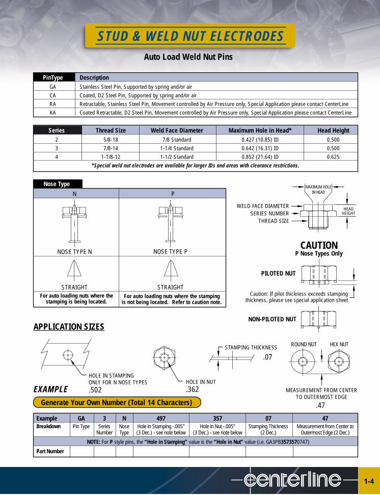
Auto Load Weld Nut Pins
PinType DescriptionGA Stainless Steel Pin, Supported by spring and/or airCA Coated, D2 Steel Pin, Supported by spring and/or airRA Retractable, Stainless Steel Pin, Movement controlled by Air Pressure only, Special Application please contact CenterLineKA Coated Retractable, D2 Steel Pin, Movement controlled by Air Pressure only, Special Application please contact CenterLine
Series Thread Size Weld Face Diameter Maximum Hole in Head* Head Height2 5/8-18 7/8 Standard 0.427 (10.85) ID 0.5003 7/8-14 1-1/4 Standard 0.642 (16.31) ID 0.5004 1-1/8-12 1-1/2 Standard 0.852 (21.64) ID 0.625
*Special weld nut electrodes are available for larger IDs and areas with clearance restrictions.
Nose Type
N P
NOSE TYPE N NOSE TYPE P
APPLICATION SIZES
CAUTIONP Nose Types Only
MAXIMUM HOLE IN HEAD
HEADHEIGHT
WELD FACE DIAMETERSERIES NUMBER
THREAD SIZE
Caution: If pilot thickness exceeds stampingthickness, please see special application sheet
HOLE IN STAMPINGONLY FOR N NOSE TYPES.502
HOLE IN NUT.362
STAMPING THICKNESS ROUND NUT
MEASUREMENT FROM CENTERTO OUTERMOST EDGE
Example GA 3 N 497 357 07 47Breakdown Pin Type Series Nose Hole in Stamping -.005” Hole in Nut -.005” Stamping Thickness Measurement from Center to
Number Type (3 Dec.) - see note below (3 Dec.) - see note below (2 Dec.) Outermost Edge (2 Dec.)
NOTE: For P style pins, the “Hole in Stamping” value is the “Hole in Nut” value (i.e. GA3PB3573570747)
Part Number
Generate Your Own Number (Total 14 Characters)
STRAIGHT STRAIGHTFor auto loading nuts where the
stamping is being located.For auto loading nuts where the stamping
is not being located. Refer to caution note.
PILOTED NUT
NON-PILOTED NUT
HEX NUT
EXAMPLE
.07
.47
STUD & WELD NUT ELECTRODES
1-5
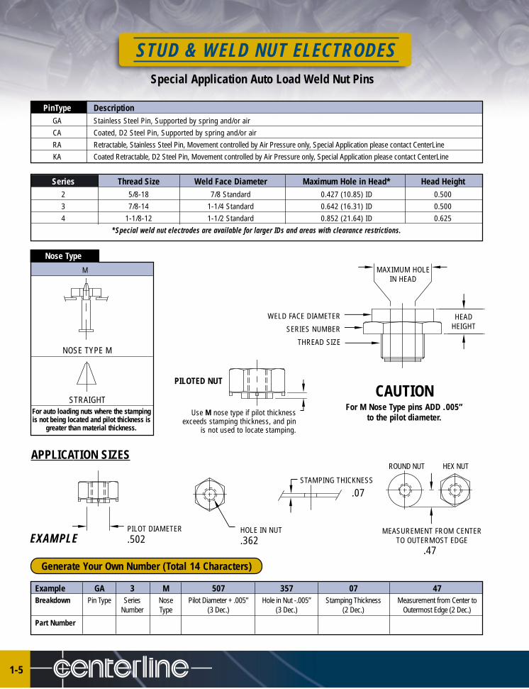
Special Application Auto Load Weld Nut Pins
PinType DescriptionGA Stainless Steel Pin, Supported by spring and/or airCA Coated, D2 Steel Pin, Supported by spring and/or airRA Retractable, Stainless Steel Pin, Movement controlled by Air Pressure only, Special Application please contact CenterLineKA Coated Retractable, D2 Steel Pin, Movement controlled by Air Pressure only, Special Application please contact CenterLine
Series Thread Size Weld Face Diameter Maximum Hole in Head* Head Height2 5/8-18 7/8 Standard 0.427 (10.85) ID 0.5003 7/8-14 1-1/4 Standard 0.642 (16.31) ID 0.5004 1-1/8-12 1-1/2 Standard 0.852 (21.64) ID 0.625
*Special weld nut electrodes are available for larger IDs and areas with clearance restrictions.
Nose Type
M
NOSE TYPE M
APPLICATION SIZES
CAUTIONFor M Nose Type pins ADD .005”
to the pilot diameter.
PILOT DIAMETER.502
STAMPING THICKNESS
ROUND NUT
MEASUREMENT FROM CENTERTO OUTERMOST EDGE
Example GA 3 M 507 357 07 47Breakdown Pin Type Series Nose Pilot Diameter + .005” Hole in Nut -.005” Stamping Thickness Measurement from Center to
Number Type (3 Dec.) (3 Dec.) (2 Dec.) Outermost Edge (2 Dec.)
Part Number
Generate Your Own Number (Total 14 Characters)
STRAIGHTFor auto loading nuts where the stampingis not being located and pilot thickness is
greater than material thickness.
HEX NUT
MAXIMUM HOLE IN HEAD
HEADHEIGHT
WELD FACE DIAMETER
SERIES NUMBER
THREAD SIZE
Use M nose type if pilot thicknessexceeds stamping thickness, and pin
is not used to locate stamping.
PILOTED NUT
HOLE IN NUT.362EXAMPLE
.07
.47
STUD & WELD NUT ELECTRODES
1-6
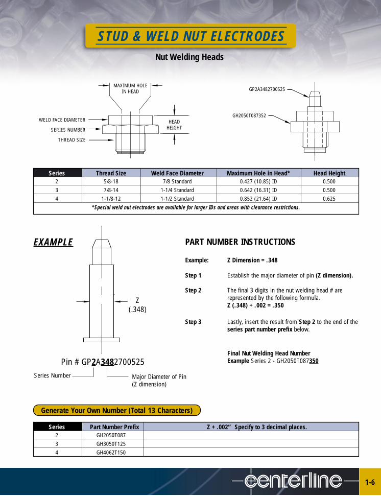
Nut Welding Heads
Series Thread Size Weld Face Diameter Maximum Hole in Head* Head Height2 5/8-18 7/8 Standard 0.427 (10.85) ID 0.5003 7/8-14 1-1/4 Standard 0.642 (16.31) ID 0.5004 1-1/8-12 1-1/2 Standard 0.852 (21.64) ID 0.625
*Special weld nut electrodes are available for larger IDs and areas with clearance restrictions.
MAXIMUM HOLE IN HEAD
HEADHEIGHT
WELD FACE DIAMETER
SERIES NUMBER
THREAD SIZE
EXAMPLE PART NUMBER INSTRUCTIONS
Example: Z Dimension = .348
Step 1 Establish the major diameter of pin (Z dimension).
Step 2 The final 3 digits in the nut welding head # are represented by the following formula.Z (.348) + .002 = .350
Step 3 Lastly, insert the result from Step 2 to the end of theseries part number prefix below.
Final Nut Welding Head Number Example Series 2 - GH2050T087350
Z(.348)
Pin # GP2A3482700525
Series Part Number Prefix Z + .002” Specify to 3 decimal places.2 GH2050T0873 GH3050T1254 GH4062T150
Generate Your Own Number (Total 13 Characters)
GP2A3482700525
GH2050T087352
Series Number Major Diameter of Pin (Z dimension)

STUD & WELD NUT ELECTRODES
1-7
Stud Welding Heads
PART NUMBER INSTRUCTIONSExample: X Dimension - .75
Y Dimension - 1.25Z Dimension - .430
Step 1 In this case, X & Y indicates Series 2 however, Zdimension dictates Series 3 or larger.
Step 2 The final 3 digits in the stud welding head # is represented by the following formula.Z (.430) + .010” = .440
Step 3 Lastly, insert the result from Step 2 to the end ofthe series part number.
Final Stud Welding Head Number Example Series 3 - GH3050T125440
X
MAXIMUM HOLE IN HEAD
HEADHEIGHT
WELD FACE DIAMETER
SERIES NUMBER
THREAD SIZE
Y
Z
Series 2
Series 3
Series 4
Series Thread Size Weld Face Diameter Maximum Hole in Head* Head Height2 5/8-18 7/8 Standard 0.427 (10.85) ID 0.5003 7/8-14 1-1/4 Standard 0.642 (16.31) ID 0.5004 1-1/8-12 1-1/2 Standard 0.852 (21.64) ID 0.625
*Special weld nut electrodes are available for larger studs and areas with clearance restrictions.
Series Part Number Prefix Z + .010” Specify to 3 decimal places.2 GH2050T0873 GH3050T1254 GH4062T150
Generate Your Own Number (Total 13 Characters)
For type U units - Max. 1.50For type X units - Max. 2.00For type U units - Max. 1.87For type X units - Max. 2.37For type U units - Max. 2.00For type X units - Max. 2.50
Series 2 - Up to 0.87 DIA.Series 3 - Up to 1.25 DIA.Series 4 - Up to 1.50 DIA.
Series 2 - Max .417Series 3 - Max .632Series 4 - Max .842
STUD & WELD NUT ELECTRODES
1-8
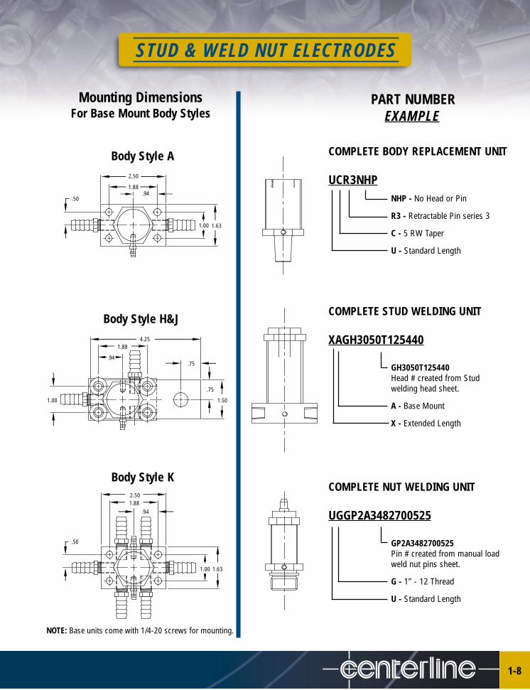
Mounting Dimensions For Base Mount Body Styles
Body Style H&J
Body Style K
PART NUMBEREXAMPLE
COMPLETE BODY REPLACEMENT UNIT
UCR3NHPNHP - No Head or Pin
R3 - Retractable Pin series 3
C - 5 RW Taper
U - Standard Length
COMPLETE STUD WELDING UNIT
XAGH3050T125440
GH3050T125440 Head # created from Studwelding head sheet.
A - Base Mount
X - Extended Length
COMPLETE NUT WELDING UNIT
UGGP2A3482700525
GP2A3482700525Pin # created from manual loadweld nut pins sheet.
G - 1” - 12 Thread
U - Standard Length
1.631.00
2.50
1.88.94
.50
4.251.88
.94.75
1.50
.75
1.00
2.501.88
.94
1.631.00
.50
Body Style A
NOTE: Base units come with 1/4-20 screws for mounting.
SMART ELECTRODES
2-1
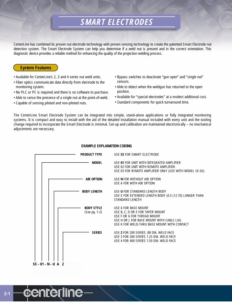
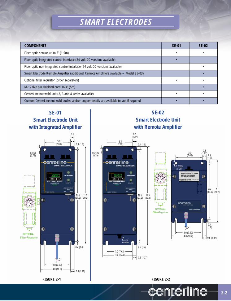
CenterLine has combined its proven nut electrode technology with proven sensing technology to create the patented Smart Electrode nutdetection system. The Smart Electrode System can help you determine if a weld nut is present and in the correct orientation. Thisdiagnostic device provides a reliable method for enhancing the quality of the projection welding process.
• Available for CenterLine’s 2, 3 and 4 series nut weld units.• Fiber optics communicate data directly from electrode to the
monitoring system.• No PLC or PC is required and there is no software to purchase.• Able to sense the presence of a single nut at the point-of-weld. • Capable of sensing piloted and non-piloted nuts.
• Bypass switches to deactivate “gun open” and “single nut”sensors.
• Able to detect when the weldgun has returned to the openposition.
• Available for “special electrodes” at a modest additional cost.• Standard components for quick turnaround time.
EXAMPLE EXPLANATION CODING
PRODUCT TYPE USE SE FOR SMART ELECTRODE
MODEL USE 01 FOR UNIT WITH INTEGRATED AMPLIFIERUSE 02 FOR UNIT WITH REMOTE AMPLIFIERUSE 03 FOR REMOTE AMPLIFIER ONLY (USE WITH MODEL SE-02)
AIR OPTION USE N FOR WITHOUT AIR OPTIONUSE A FOR WITH AIR OPTION
BODY LENGTH USE U FOR STANDARD LENGTH BODYUSE X FOR EXTENDED LENGTH BODY (0.5 (12.70) LONGER THANSTANDARD LENGTH
BODY STYLE USE A FOR BASE MOUNT(See pg. 1-2) USE B, C, D OR E FOR TAPER MOUNT
USE F OR G FOR THREAD MOUNTUSE H OR J FOR BASE MOUNT WITH CABLE LUGUSE K FOR WELD-THRU BASE MOUNT WITH CONTACT
SERIES USE 2 FOR 200 SERIES .88 DIA. WELD FACEUSE 3 FOR 300 SERIES 1.25 DIA. WELD FACEUSE 4 FOR 400 SERIES 1.50 DIA. WELD FACE
SE - 01 - N - U A 2
The CenterLine Smart Electrode System can be integrated into simple, stand-alone applications or fully integrated monitoringsystems. It is compact and easy to install with the aid of the detailed installation manual included with every unit and the toolingchange required to incorporate the Smart Electrode is minimal. Set-up and calibration are maintained electronically – no mechanicaladjustments are necessary.
System Features
SMART ELECTRODES
2-2
SE-02Smart Electrode Unit
with Remote Amplifier
SE-01Smart Electrode Unit
with Integrated Amplifier
COMPONENTS SE-01 SE-02
Fiber optic sensor up to 5’ (1.5m) • •
Fiber optic integrated control interface (24 volt DC versions available) •
Fiber optic non-integrated control interface (24 volt DC versions available) •
Smart Electrode Remote Amplifier (additional Remote Amplifiers available – Model SE-03) •
Optional filter regulator (order separately) • •
M-12 five pin shielded cord 16.4’ (5m) •
CenterLine nut weld unit (2, 3 and 4 series available) • •
Custom CenterLine nut weld bodies and/or copper details are available to suit if required • •
FIGURE 2-2FIGURE 2-1
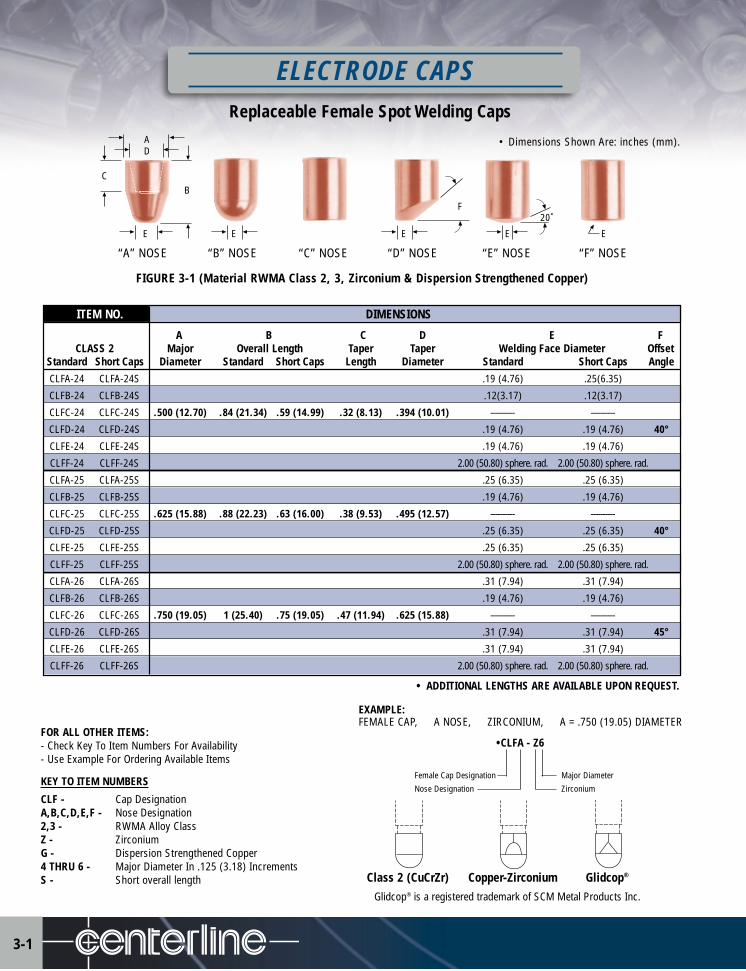
ITEM NO. DIMENSIONS
A B C D E FCLASS 2 Major Overall Length Taper Taper Welding Face Diameter Offset
Standard Short Caps Diameter Standard Short Caps Length Diameter Standard Short Caps AngleCLFA-24 CLFA-24S .19 (4.76) .25(6.35)
CLFB-24 CLFB-24S .12(3.17) .12(3.17)
CLFC-24 CLFC-24S .500 (12.70) .84 (21.34) .59 (14.99) .32 (8.13) .394 (10.01) ---------- ----------
CLFD-24 CLFD-24S .19 (4.76) .19 (4.76) 40°
CLFE-24 CLFE-24S .19 (4.76) .19 (4.76)
CLFF-24 CLFF-24S 2.00 (50.80) sphere. rad. 2.00 (50.80) sphere. rad.
CLFA-25 CLFA-25S .25 (6.35) .25 (6.35)
CLFB-25 CLFB-25S .19 (4.76) .19 (4.76)
CLFC-25 CLFC-25S .625 (15.88) .88 (22.23) .63 (16.00) .38 (9.53) .495 (12.57) ---------- ----------
CLFD-25 CLFD-25S .25 (6.35) .25 (6.35) 40°
CLFE-25 CLFE-25S .25 (6.35) .25 (6.35)
CLFF-25 CLFF-25S 2.00 (50.80) sphere. rad. 2.00 (50.80) sphere. rad.
CLFA-26 CLFA-26S .31 (7.94) .31 (7.94)
CLFB-26 CLFB-26S .19 (4.76) .19 (4.76)
CLFC-26 CLFC-26S .750 (19.05) 1 (25.40) .75 (19.05) .47 (11.94) .625 (15.88) ---------- ----------
CLFD-26 CLFD-26S .31 (7.94) .31 (7.94) 45°
CLFE-26 CLFE-26S .31 (7.94) .31 (7.94)
CLFF-26 CLFF-26S 2.00 (50.80) sphere. rad. 2.00 (50.80) sphere. rad.
FIGURE 3-1 (Material RWMA Class 2, 3, Zirconium & Dispersion Strengthened Copper)
Replaceable Female Spot Welding Caps
Female Cap Designation Major Diameter
Nose Designation Zirconium
Glidcop® is a registered trademark of SCM Metal Products Inc.
CB
DA
E E E E E
F20˚
ELECTRODE CAPS
•CLFA - Z6
3-1
“A” NOSE “B” NOSE “C” NOSE “D” NOSE “E” NOSE “F” NOSE
• Dimensions Shown Are: inches (mm).
FOR ALL OTHER ITEMS:- Check Key To Item Numbers For Availability- Use Example For Ordering Available Items
KEY TO ITEM NUMBERS
CLF - Cap DesignationA,B,C,D,E,F - Nose Designation2,3 - RWMA Alloy ClassZ - ZirconiumG - Dispersion Strengthened Copper4 THRU 6 - Major Diameter In .125 (3.18) IncrementsS - Short overall length
• ADDITIONAL LENGTHS ARE AVAILABLE UPON REQUEST.
EXAMPLE:FEMALE CAP, A NOSE, ZIRCONIUM, A = .750 (19.05) DIAMETER
Class 2 (CuCrZr) Copper-Zirconium Glidcop®
E
20˚
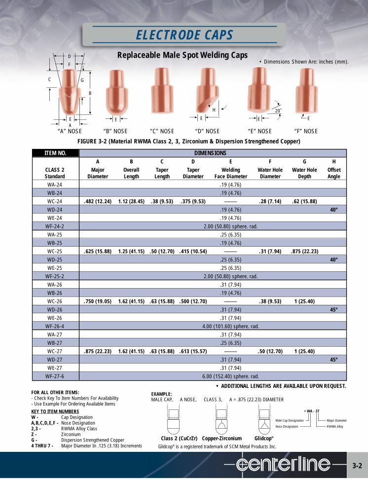
FIGURE 3-2 (Material RWMA Class 2, 3, Zirconium & Dispersion Strengthened Copper)
ITEM NO. DIMENSIONSA B C D E F G H
CLASS 2 Major Overall Taper Taper Welding Water Hole Water Hole OffsetStandard Diameter Length Length Diameter Face Diameter Diameter Depth AngleWA-24 .19 (4.76)WB-24 .19 (4.76)WC-24 .482 (12.24) 1.12 (28.45) .38 (9.53) .375 (9.53) ---------- .28 (7.14) .62 (15.88)WD-24 .19 (4.76) 40°WE-24 .19 (4.76)
WF-24-2 2.00 (50.80) sphere. rad.WA-25 .25 (6.35)WB-25 .19 (4.76)WC-25 .625 (15.88) 1.25 (41.15) .50 (12.70) .415 (10.54) ---------- .31 (7.94) .875 (22.23)WD-25 .25 (6.35) 40°WE-25 .25 (6.35)
WF-25-2 2.00 (50.80) sphere. rad.WA-26 .31 (7.94)WB-26 .19 (4.76)WC-26 .750 (19.05) 1.62 (41.15) .63 (15.88) .500 (12.70) ---------- .38 (9.53) 1 (25.40)WD-26 .31 (7.94) 45°WE-26 .31 (7.94)
WF-26-4 4.00 (101.60) sphere. rad.WA-27 .31 (7.94)WB-27 .25 (6.35)WC-27 .875 (22.23) 1.62 (41.15) .63 (15.88) .613 (15.57) ---------- .50 (12.70) 1 (25.40)WD-27 .31 (7.94) 45°WE-27 .31 (7.94)
WF-27-6 6.00 (152.40) sphere. rad.
• WA - 37
Male Cap Designation Major Diameter
Nose Designation RWMA Alloy
C G
B
D
F
AE E E E
H
ELECTRODE CAPSReplaceable Male Spot Welding Caps
2-2
FOR ALL OTHER ITEMS:- Check Key To Item Numbers For Availability- Use Example For Ordering Available Items
KEY TO ITEM NUMBERSW - Cap DesignationA,B,C,D,E,F - Nose Designation2,3 - RWMA Alloy ClassZ - ZirconiumG - Dispersion Strengthened Copper4 THRU 7 - Major Diameter In .125 (3.18) Increments
“A” NOSE “B” NOSE “C” NOSE “D” NOSE “E” NOSE “F” NOSE
• Dimensions Shown Are: inches (mm).
Glidcop® is a registered trademark of SCM Metal Products Inc.
Class 2 (CuCrZr) Copper-Zirconium Glidcop®
• ADDITIONAL LENGTHS ARE AVAILABLE UPON REQUEST.EXAMPLE:MALE CAP, A NOSE, CLASS 3, A = .875 (22.23) DIAMETER
3-2
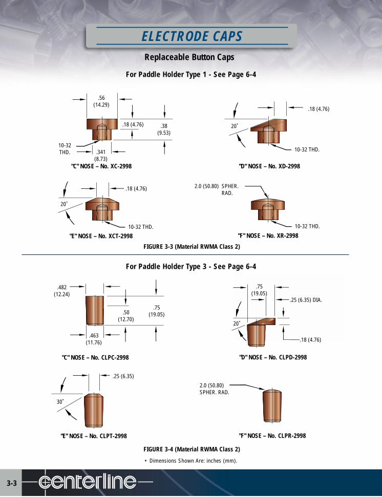
Replaceable Button Caps
ELECTRODE CAPS
3-3
For Paddle Holder Type 1 - See Page 6-4
.56(14.29)
"C" NOSE – No. XC-2998
.18 (4.76) .38(9.53)
.341(8.73)
10-32THD.
"D" NOSE – No. XD-2998
20˚
.18 (4.76)
"E" NOSE – No. XCT-2998
20˚
.18 (4.76)
"F" NOSE – No. XR-2998
2.0 (50.80) SPHER.RAD.
10-32 THD. 10-32 THD.
10-32 THD.
"C" NOSE – No. CLPC-2998
.75(19.05).50
(12.70)
.463(11.76)
.482(12.24)
"E" NOSE – No. CLPT-2998
30˚
.25 (6.35)
"F" NOSE – No. CLPR-2998
2.0 (50.80)SPHER. RAD.
"D" NOSE – No. CLPD-2998
20˚
.75(19.05)
.25 (6.35) DIA.
.18 (4.76)
20˚
.75(19.05)
.25 (6.35) DIA.
.18 (4.76)
For Paddle Holder Type 3 - See Page 6-4
FIGURE 3-4 (Material RWMA Class 2)
• Dimensions Shown Are: inches (mm).
FIGURE 3-3 (Material RWMA Class 2)

ELECTRODE CAPSButton Caps
3-4
“Y” = NOSE DESIGNATION
* A = Pointed* B = Dome
C = Flat (Shown)* E = Truncated (20°)
F = .62 (15.88) Radius
* 0.25(6.35) Weld Face Diameter
• Dimensions Shown Are: inches (mm).
3/8-16 THD.
.62 (15.88) DIAMETER
.375(9.53)
A
3/8-16 THD.
.50 (12.70) HEX
.375(9.53)
A
For Paddle Holder Type 2 – See Page 6-4
NOTE: Other thread sizes and shapes are available.
EXAMPLE – CLR2-78-AY
CLR2-78 = RWMA Class 2CLR3-78 = RWMA Class 3CLRZ-78 = Zirconium
EXAMPLE – CLH3-78-AY
CLH2-78 = RWMA Class 2CLH3-78 = RWMA Class 3
FIGURE 3-5 (Material RWMA Class 2, 3 & Zirconium)
FIGURE 3-6 (Material RWMA Class 2 & 3)
EXAMPLE: .50 (12.70) HEX, CLASS 3, “A” = .50 (12.70) HEIGHT, C = FLAT NOSE.
• CLH3-78-50C
Item No.
Use H for Hex MaterialUse R for Round Material
RWMA Alloy Class
“Y” Nose Designation
“A” Height
ITEM NO. “A” = HEIGHTCLR2-78-31C .312 (7.92)
CLR2-78-37C .375 (9.53)
CLR2-78-43C .437 (11.10)
CLR2-78-50C .500 (12.70)
CLR2-78-62C .625 (15.88)
CLR2-78-75C .750 (19.05)
ETC. See Example
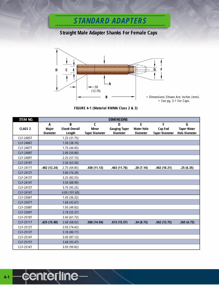
Straight Male Adapter Shanks For Female Caps
STANDARD ADAPTERS
4-1
• Dimensions Shown Are: inches (mm).• See pg. 3-1 For Caps.
FIGURE 4-1 (Material RWMA Class 2 & 3)
.50(12.70)
D C E
A
B
FG
ITEM NO. DIMENSIONSA B C D E F G
CLASS 2 Major Shank Overall Minor Gauging Taper Water Hole Cap End Taper WaterDiameter Length Taper Diameter Diameter Diameter Taper Diameter Hole Diameter
CLF-2405T 1.25 (31.75)CLF-2406T 1.50 (38.10)CLF-2407T 1.75 (44.45)CLF-2408T 2.00 (50.80)CLF-2409T 2.25 (57.15)CLF-2410T 2.50 (63.50)CLF-2411T .482 (12.24) 2.75 (69.85) .438 (11.13) .463 (11.76) .28 (7.14) .402 (10.21) .25 (6.35)CLF-2412T 3.00 (76.20)CLF-2413T 3.25 (82.55)CLF-2414T 3.50 (88.90)CLF-2415T 3.75 (95.25)CLF-2416T 4.00 (101.60)CLF-2506T 1.43 (36.32)CLF-2507T 1.68 (42.67)CLF-2508T 1.93 (49.02)CLF-2509T 2.18 (55.37)CLF-2510T 2.43 (61.72)CLF-2511T .625 (15.88) 2.68 (68.02) .588 (14.94) .613 (15.57) .34 (8.73) .502 (12.75) .265 (6.73)CLF-2512T 2.93 (74.42)CLF-2513T 3.18 (80.77)CLF-2514T 3.43 (87.12)CLF-2515T 3.68 (93.47)CLF-2516T 3.93 (99.82)
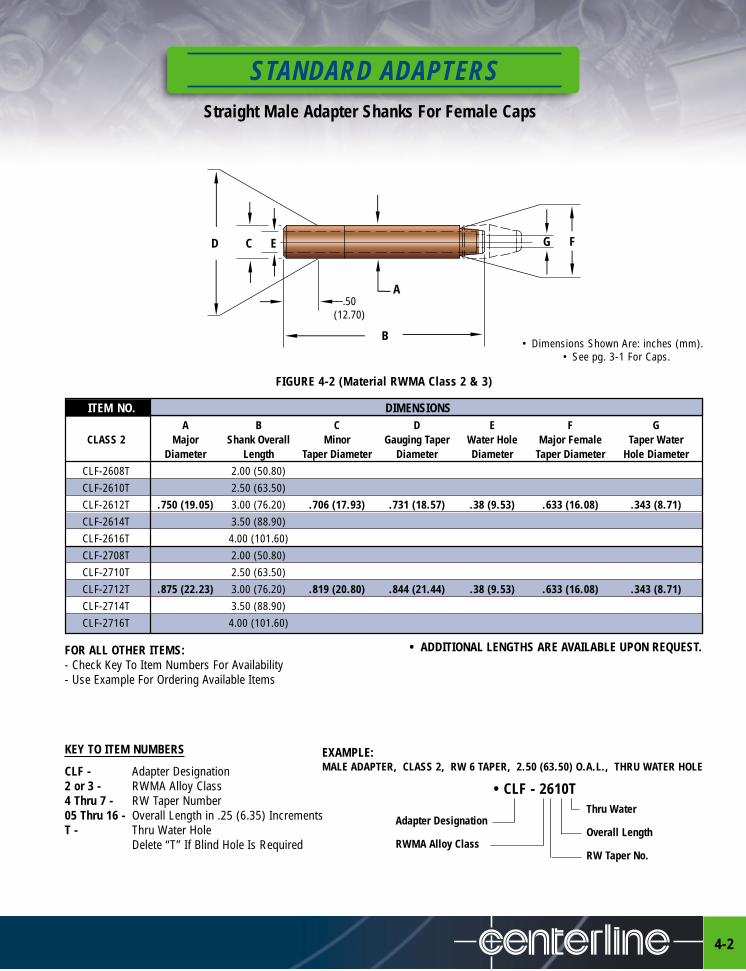
STANDARD ADAPTERSStraight Male Adapter Shanks For Female Caps
4-2
• Dimensions Shown Are: inches (mm).• See pg. 3-1 For Caps.
FIGURE 4-2 (Material RWMA Class 2 & 3)
FOR ALL OTHER ITEMS:- Check Key To Item Numbers For Availability- Use Example For Ordering Available Items
KEY TO ITEM NUMBERS
CLF - Adapter Designation2 or 3 - RWMA Alloy Class4 Thru 7 - RW Taper Number 05 Thru 16 - Overall Length in .25 (6.35) IncrementsT - Thru Water Hole
Delete “T” If Blind Hole Is Required
EXAMPLE:MALE ADAPTER, CLASS 2, RW 6 TAPER, 2.50 (63.50) O.A.L., THRU WATER HOLE
• CLF - 2610TThru Water
Adapter DesignationOverall Length
RWMA Alloy ClassRW Taper No.
.50(12.70)
C E
A
B
D FG
ITEM NO. DIMENSIONSA B C D E F G
CLASS 2 Major Shank Overall Minor Gauging Taper Water Hole Major Female Taper WaterDiameter Length Taper Diameter Diameter Diameter Taper Diameter Hole Diameter
CLF-2608T 2.00 (50.80)CLF-2610T 2.50 (63.50)CLF-2612T .750 (19.05) 3.00 (76.20) .706 (17.93) .731 (18.57) .38 (9.53) .633 (16.08) .343 (8.71)CLF-2614T 3.50 (88.90)CLF-2616T 4.00 (101.60)CLF-2708T 2.00 (50.80)CLF-2710T 2.50 (63.50)CLF-2712T .875 (22.23) 3.00 (76.20) .819 (20.80) .844 (21.44) .38 (9.53) .633 (16.08) .343 (8.71)CLF-2714T 3.50 (88.90)CLF-2716T 4.00 (101.60)
• ADDITIONAL LENGTHS ARE AVAILABLE UPON REQUEST.

Straight Female Adapter Shanks For Male Caps
STANDARD ADAPTERS
4-3
ITEM NO. DIMENSIONSA B C D E F
CLASS 2 Major Shank Overall Minor Gauging Taper Water Hole Major FemaleDiameter Length Taper Diameter Diameter Diameter Taper Diameter
WG-2405 1.25 (31.75)WG-2406 1.50 (38.10)WG-2407 1.75 (44.45)WG-2408 2.00 (50.80)WG-2409 2.25 (57.15)WG-2410 2.50 (63.50)WG-2411 .482 (12.24) 2.75 (69.85) .438 (11.13) .463 (11.76) .28 (7.14) .375 (9.53)WG-2412 3.00 (76.20)WG-2413 3.25 (82.55)WG-2414 3.50 (88.90)WG-2415 3.75 (95.25)WG-2416 4.00 (101.60)WG-2505 1.25 (31.75)WG-2506 1.50 (38.10)WG-2507 1.75 (44.45)WG-2508 2.00 (50.80)WG-2509 2.25 (57.15)WG-2510 2.50 (63.50)WG-2511 .625 (15.88) 2.75 (69.85) .588 (14.94) .613 (15.57) .38 (9.53) .415 (10.54)WG-2512 3.00 (76.20)WG-2513 3.25 (82.55)WG-2514 3.50 (88.90)WG-2515 3.75 (95.25)WG-2516 4.00 (101.60)
• Dimensions Shown Are: inches (mm).• See pg. 3-2 For Caps.
FIGURE 4-3 (Material RWMA Class 2 & 3)
.50(12.70)
D C E
A
B
F
• ADDITIONAL LENGTHS ARE AVAILABLE UPON REQUEST.
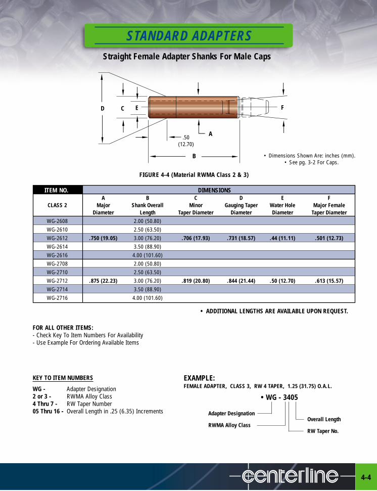
STANDARD ADAPTERSStraight Female Adapter Shanks For Male Caps
4-4
• Dimensions Shown Are: inches (mm).• See pg. 3-2 For Caps.
FIGURE 4-4 (Material RWMA Class 2 & 3)
EXAMPLE:FEMALE ADAPTER, CLASS 3, RW 4 TAPER, 1.25 (31.75) O.A.L.
• WG - 3405
Adapter DesignationOverall Length
RWMA Alloy ClassRW Taper No.
.50(12.70)
D C E
A
B
F
FOR ALL OTHER ITEMS:- Check Key To Item Numbers For Availability- Use Example For Ordering Available Items
KEY TO ITEM NUMBERS
WG - Adapter Designation2 or 3 - RWMA Alloy Class4 Thru 7 - RW Taper Number 05 Thru 16 - Overall Length in .25 (6.35) Increments
ITEM NO. DIMENSIONSA B C D E F
CLASS 2 Major Shank Overall Minor Gauging Taper Water Hole Major FemaleDiameter Length Taper Diameter Diameter Diameter Taper Diameter
WG-2608 2.00 (50.80)WG-2610 2.50 (63.50)WG-2612 .750 (19.05) 3.00 (76.20) .706 (17.93) .731 (18.57) .44 (11.11) .501 (12.73)WG-2614 3.50 (88.90)WG-2616 4.00 (101.60)WG-2708 2.00 (50.80)WG-2710 2.50 (63.50)WG-2712 .875 (22.23) 3.00 (76.20) .819 (20.80) .844 (21.44) .50 (12.70) .613 (15.57)WG-2714 3.50 (88.90)WG-2716 4.00 (101.60)
• ADDITIONAL LENGTHS ARE AVAILABLE UPON REQUEST.
FOR ALL OTHER ITEMS: • ADDITIONAL LENGTHS ARE AVAILABLE UPON REQUEST.- Check Key To Item Numbers For Availability- Use Example For Ordering Available Items
KEY TO ITEM NUMBERS
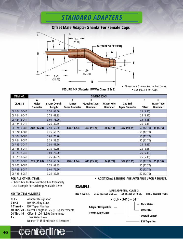
CLF - Adapter Designation2 or 3 - RWMA Alloy Class4 Thru 6 - RW Taper Number 10 Thru 20 - Overall Length in .25 (6.35) Increments04 Thru 16 - Offset in .06 (1.59) IncrementsT - Thru Water Hole
Delete “T” If Blind Hole Is Required
Offset Male Adapter Shanks For Female Caps
STANDARD ADAPTERS
4-5
FIGURE 4-5 (Material RWMA Class 2 & 3)
ITEM NO. DIMENSIONSA B C D E F G H
CLASS 2 Major Shank Overall Minor Gauging Taper Water Hole Cap End Water TubeDiameter Length Taper Diameter Diameter Diameter Taper Diameter Offset Diameter
CLF-2410-04T 2.50 (63.50) .25 (6.35)CLF-2411-04T 2.75 (69.85) .25 (6.35)CLF-2412-04T 3.00 (76.20) .25 (6.35)CLF-2413-04T 3.25 (82.55) .25 (6.35)CLF-2410-08T .482 (12.24) 2.50 (63.50) .438 (11.13) .463 (11.76) .28 (7.14) .402 (10.21) .50 (12.70) .19 (4.76)CLF-2411-08T 2.75 (69.85) .50 (12.70)CLF-2412-08T 3.00 (76.20) .50 (12.70)CLF-2413-08T 3.25 (82.55) .50 (12.70)CLF-2510-04T 2.50 (63.50) .25 (6.35)CLF-2511-04T 2.75 (69.85) .25 (6.35)CLF-2512-04T 3.00 (76.20) .25 (6.35)CLF-2513-04T 3.25 (82.55) .25 (6.35)CLF-2510-08T .625 (15.88) 2.50 (63.50) .588 (14.94) .613 (15.57) .34 (8.73) .502 (12.75) .50 (12.70) .25 (6.35)CLF-2511-08T 2.75 (69.85) .50 (12.70)CLF-2512-08T 3.00 (76.20) .50 (12.70)CLF-2513-08T 3.25 (82.55) .50 (12.70)
EXAMPLE:MALE ADAPTER, CLASS 3,
RW 4 TAPER, 2.50 (63.50) O.A.L., .25 (6.35) OFFSET, THRU WATER HOLE
• CLF - 3410 - 04TThru Water
Adapter DesignationOffset (G)
RWMA Alloy ClassOverall Length
RW Taper No.
1.0(25.40)
G (TO BE SPECIFIED)
.50(12.70)
1.25(31.75)
D
HC
E
B
A
F
• Dimensions Shown Are: inches (mm).• See pg. 3-1 For Caps.

FOR ALL OTHER ITEMS: • ADDITIONAL LENGTHS ARE AVAILABLE UPON REQUEST.- Check Key To Item Numbers For Availability- Use Example For Ordering Available Items
KEY TO ITEM NUMBERS
WG - Adapter Designation2 or 3 - RWMA Alloy Class4 Thru 6 - RW Taper Number 10 Thru 20 - Overall Length
in .25 (6.35) Increments04 Thru 16 - Offset in .06 (1.59) Increments
STANDARD ADAPTERSOffset Female Adapter Shanks for Male Caps
4-6
FIGURE 4-6 (Material RWMA Class 2 & 3)
EXAMPLE:FEMALE ADAPTER, CLASS 2,
RW 5 TAPER, 3.25 (82.55) O.A.L., 1.0 (25.40) OFFSET.
• WG - 2513 - 16
Adapter DesignationOffset (G)
RWMA Alloy ClassOverall Length
RW Taper No.
1.0(25.40)
G (TO BE SPECIFIED)
.50(12.70)
1.25(31.75)
D
HC
E
B
A
F
ITEM NO. DIMENSIONSA B C D E F G H
CLASS 2 Major Shank Overall Minor Gauging Taper Water Hole Cap End Offset Water TubeDiameter Length Taper Diameter Diameter Diameter Taper Diameter Diameter
WG-2410-04 2.50 (63.50) .25 (6.35)WG-2411-04 2.75 (69.85) .25 (6.35)WG-2412-04 3.00 (76.20) .25 (6.35)WG-2413-04 3.25 (82.55) .25 (6.35)WG-2410-08 .482 (12.24) 2.50 (63.50) .438 (11.13) .463 (11.76) .28 (7.14) .375 (9.53) .50 (12.70) .19 (4.76)WG-2411-08 2.75 (69.85) .50 (12.70)WG-2412-08 3.00 (76.20) .50 (12.70)WG-2413-08 3.25 (82.55) .50 (12.70)WG-2510-04 2.50 (63.50) .25 (6.35)WG-2511-04 2.75 (69.85) .25 (6.35)WG-2512-04 3.00 (76.20) .25 (6.35)WG-2513-04 3.25 (82.55) .25 (6.35)WG-2510-08 .625 (15.88) 2.50 (63.50) .588 (14.94) .613 (15.57) .38 (9.65) .415 (10.54) .50 (12.70) .25 (6.35)WG-2511-08 2.75 (69.85) .50 (12.70)WG-2512-08 3.00 (76.20) .50 (12.70)WG-2513-08 3.25 (82.55) .50 (12.70)
• Dimensions Shown Are: inches (mm).• See pg. 3-2 For Caps.

Single Bend Male Adapter Shanks For Female Caps
STANDARD ADAPTERS
4-7
DIMENSION CHARTS
• TO ORDER YOUR SPECIALS USE CODING CHART - SEE PG. 4-8
H – CAP SIZE .500 (12.70) .625 (15.88) .750 (19.05)
E – HOLE DIAMETER .28 (7.11) .31 (7.87) .34 (8.64)F – HOLE DIAMETER .38 (9.65) .38 (9.65) .38 (9.65)G – TAPER DIAMETER .402 (10.21) .502 (12.75) .633 (16.08)
1.25(31.75)
C
1.00(25.40)
2.12(53.98)
F E
H
A
D˚
B
G
WATER TUBE.25 (6.35) O.D.
FIGURE 4-7 (Material RWMA Class 3)
• Dimensions Shown Are: inches (mm).• See pg. 3-1 For Caps.
C – DIAMETER .625 (15.88) .750 (19.05) .88 (22.35)C – DIAMETER CODE 5 6 7
A – OVERALL LENGTH AS CODEDB – OFFSET AS CODEDD – ANGLE AS CODED

STANDARD ADAPTERSSingle Bend Male Adapter Shanks For Female Caps
4-8
EXAMPLE EXPLANATION CODING
CENTERLINE SPECIALS USE CF FOR SINGLE BEND MALE ADAPTERS FOR FEMALE CAPS
CAP SIZE USE 0 FOR .50 (12.70) NOMINAL DIAMETERUSE 1 FOR .62 (15.88) NOMINAL DIAMETERUSE 2 FOR .75 (19.05) NOMINAL DIAMETER
MATERIAL USE 3 FOR CLASS 3 RWMA
C = ADAPTER DIAMETER USE 5 FOR .62 (15.88) NOMINAL DIAMETER STRAIGHT SHANK(IN .125 (3.18) INCREMENTS) USE 6 FOR .75 (19.05) NOMINAL DIAMETER STRAIGHT SHANK
USE 7 FOR .88 (22.35) NOMINAL DIAMETER STRAIGHT SHANKUSE 5E FOR .62 (15.88) NOMINAL DIAMETER ELECTRODE TAPER SHANK USE 6E FOR .75 (19.05) NOMINAL DIAMETER ELECTRODE TAPER SHANKUSE 7E FOR .88 (22.35) NOMINAL DIAMETER ELECTRODE TAPER SHANK
A = OVERALL LENGTH USE 10 FOR 2.50 (63.50) MINIMUM LENGTH(IN .25 (6.35) INCREMENTS)
B = OFFSET LENGTH USE 8 FOR 1.0 (25.40) MINIMUM OFFSET(IN .125 (3.18) INCREMENTS)
D = OFFSET ANGLE USE 45 FOR 45° OFFSET(AS CODED) USE 60 FOR 60° OFFSET
USE 75 FOR 75° OFFSETUSE 90 FOR 90° OFFSET
WATER HOLE THRU USE T FOR WATER HOLE THRUOMIT T FOR BLIND HOLE CAP TAPER END ONLY
CF 1 - 3 5 10 8 90 T
SAMPLETYPICAL CAP ADAPTER CODING
CAP ADAPTER WATER HOLE WILL BE DRILLED THRUCAP ADAPTER OFFSET ANGLE WILL BE 90°CAP ADAPTER OFFSET WILL BE 1.0 (25.40) LONGCAP ADAPTER WILL BE 2.50 (63.50) LONGCAP ADAPTER WILL HAVE .62 (15.88) DIAMETERCAP ADAPTER WILL BE MADE OF CLASS 3 RWMA MATERIALCAP ADAPTER WILL HAVE A STRAIGHT SHANKCAP ADAPTER WILL BE SINGLE BEND MALE FOR FEMALE CAPS
EXAMPLE:• CF1-3510890T
• Dimensions Shown Are: inches (mm)
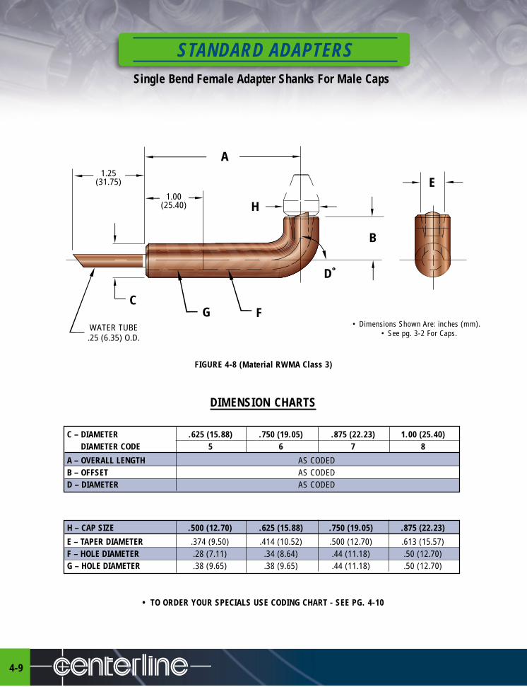
Single Bend Female Adapter Shanks For Male Caps
STANDARD ADAPTERS
4-9
DIMENSION CHARTS
• TO ORDER YOUR SPECIALS USE CODING CHART - SEE PG. 4-10
C – DIAMETER .625 (15.88) .750 (19.05) .875 (22.23) 1.00 (25.40)C – DIAMETER CODE 5 6 7 8
A – OVERALL LENGTH AS CODEDB – OFFSET AS CODEDD – DIAMETER AS CODED
H – CAP SIZE .500 (12.70) .625 (15.88) .750 (19.05) .875 (22.23)
E – TAPER DIAMETER .374 (9.50) .414 (10.52) .500 (12.70) .613 (15.57)F – HOLE DIAMETER .28 (7.11) .34 (8.64) .44 (11.18) .50 (12.70)G – HOLE DIAMETER .38 (9.65) .38 (9.65) .44 (11.18) .50 (12.70)
1.25(31.75)
C
WATER TUBE.25 (6.35) O.D.
1.00(25.40)
G F
H
A
D˚
B
E
• Dimensions Shown Are: inches (mm).• See pg. 3-2 For Caps.
FIGURE 4-8 (Material RWMA Class 3)

STANDARD ADAPTERSSingle Bend Female Adapter Shanks For Male Caps
4-10
EXAMPLE EXPLANATION CODING
CENTERLINE SPECIALS USE CM FOR SINGLE BEND FEMALE ADAPTER FOR MALE CAPS
CAP SIZE USE 0 FOR .50 (12.70) NOMINAL DIAMETER(IN .125 (3.18) INCREMENTS) USE 1 FOR .625 (15.88) NOMINAL DIAMETER
USE 2 FOR .75 (19.05) NOMINAL DIAMETERUSE 3 FOR .75 (19.05) NOMINAL DIAMETER (INCREASED WATER FLOW)USE 4 FOR .875 (22.23) NOMINAL DIAMETER
MATERIAL USE 3 FOR CLASS 3 RWMA
C = ADAPTER DIAMETER USE 5 FOR .62 (15.88) NOMINAL DIAMETER STRAIGHT SHANK(IN .125 (3.18) INCREMENTS) USE 6 FOR .75 (19.05) NOMINAL DIAMETER STRAIGHT SHANK
USE 7 FOR .88 (22.35) NOMINAL DIAMETER STRAIGHT SHANKUSE 8 FOR 1 (25.40) NOMINAL DIAMETER STRAIGHT SHANKUSE 5E FOR .62 (15.88) NOMINAL ELECTRODE TAPERED SHANKUSE 6E FOR .75 (19.05) NOMINAL ELECTRODE TAPERED SHANKUSE 7E FOR .88 (22.35) NOMINAL ELECTRODE TAPERED SHANK
A = OVERALL LENGTH USE 10 FOR 2.50 (63.50) MINIMUM LENGTH(IN .25 (6.35) INCREMENTS)
B = OFFSET LENGTH USE 8 FOR 1.0 (25.40) MINIMUM OFFSET(IN .125 (3.18) INCREMENTS)
D = OFFSET ANGLE USE 45 FOR 45° OFFSET(AS CODED) USE 60 FOR 60° OFFSET
USE 75 FOR 75° OFFSETUSE 90 FOR 90° OFFSET
CM 1 - 3 6 10 6 90
SAMPLETYPICAL CAP ADAPTER CODING
CAP ADAPTER OFFSET ANGLE WILL BE 90°CAP ADAPTER OFFSET WILL BE 1.0 (25.40) LONGCAP ADAPTER WILL BE 2.50 (63.50) LONGCAP ADAPTER WILL HAVE .62 (15.88) DIAMETERCAP ADAPTER WILL BE MADE OF CLASS 3 RWMA MATERIALCAP ADAPTER WILL HAVE A STRAIGHT SHANKCAP ADAPTER WILL BE SINGLE BEND FEMALE FOR MALE CAPS
EXAMPLE:
• CM1-3610690
• Dimensions Shown Are: inches (mm)
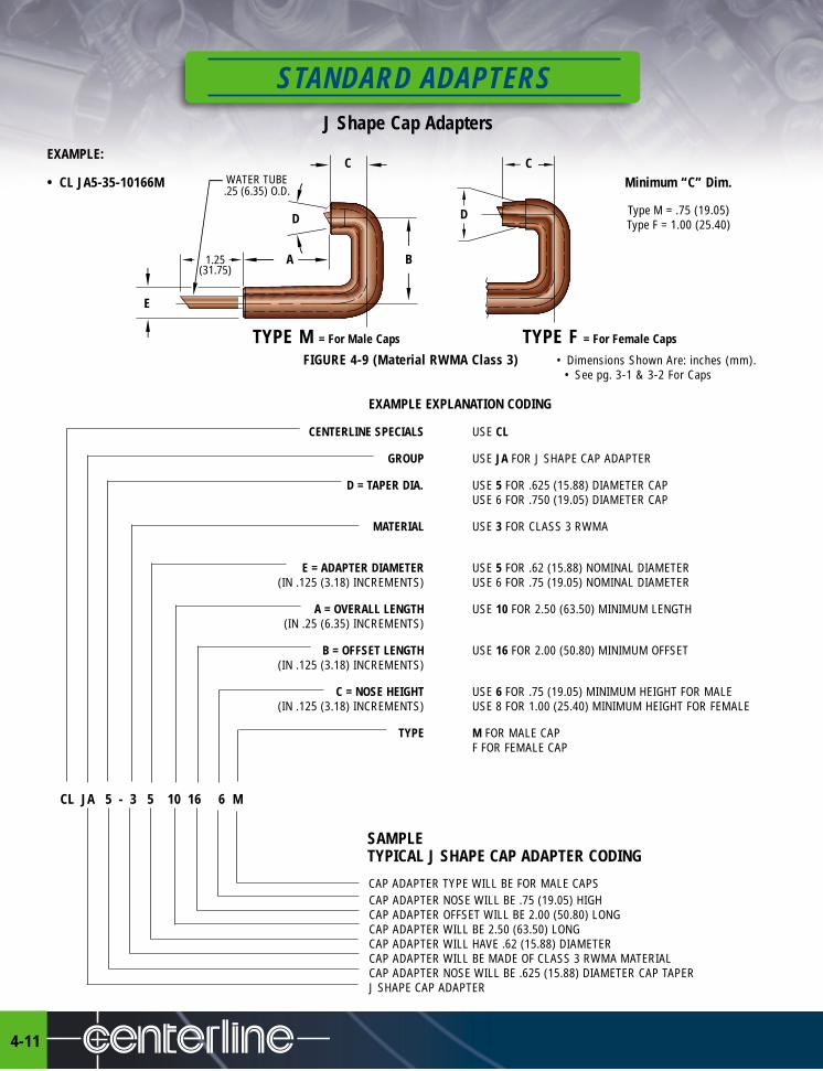
J Shape Cap Adapters
STANDARD ADAPTERS
4-11
EXAMPLE:
• CL JA5-35-10166M Minimum “C” Dim.
Type M = .75 (19.05)Type F = 1.00 (25.40)
TYPE M = For Male Caps TYPE F = For Female Caps
FIGURE 4-9 (Material RWMA Class 3)
EXAMPLE EXPLANATION CODING
CENTERLINE SPECIALS USE CL
GROUP USE JA FOR J SHAPE CAP ADAPTER
D = TAPER DIA. USE 5 FOR .625 (15.88) DIAMETER CAPUSE 6 FOR .750 (19.05) DIAMETER CAP
MATERIAL USE 3 FOR CLASS 3 RWMA
E = ADAPTER DIAMETER USE 5 FOR .62 (15.88) NOMINAL DIAMETER(IN .125 (3.18) INCREMENTS) USE 6 FOR .75 (19.05) NOMINAL DIAMETER
A = OVERALL LENGTH USE 10 FOR 2.50 (63.50) MINIMUM LENGTH(IN .25 (6.35) INCREMENTS)
B = OFFSET LENGTH USE 16 FOR 2.00 (50.80) MINIMUM OFFSET(IN .125 (3.18) INCREMENTS)
C = NOSE HEIGHT USE 6 FOR .75 (19.05) MINIMUM HEIGHT FOR MALE(IN .125 (3.18) INCREMENTS) USE 8 FOR 1.00 (25.40) MINIMUM HEIGHT FOR FEMALE
TYPE M FOR MALE CAPF FOR FEMALE CAP
CL JA 5 - 3 5 10 16 6 M
CAP ADAPTER NOSE WILL BE .75 (19.05) HIGHCAP ADAPTER OFFSET WILL BE 2.00 (50.80) LONGCAP ADAPTER WILL BE 2.50 (63.50) LONGCAP ADAPTER WILL HAVE .62 (15.88) DIAMETERCAP ADAPTER WILL BE MADE OF CLASS 3 RWMA MATERIALCAP ADAPTER NOSE WILL BE .625 (15.88) DIAMETER CAP TAPERJ SHAPE CAP ADAPTER
WATER TUBE.25 (6.35) O.D.
C
D
A1.25(31.75)
E
B
C
D
CAP ADAPTER TYPE WILL BE FOR MALE CAPS
SAMPLETYPICAL J SHAPE CAP ADAPTER CODING
• Dimensions Shown Are: inches (mm).• See pg. 3-1 & 3-2 For Caps
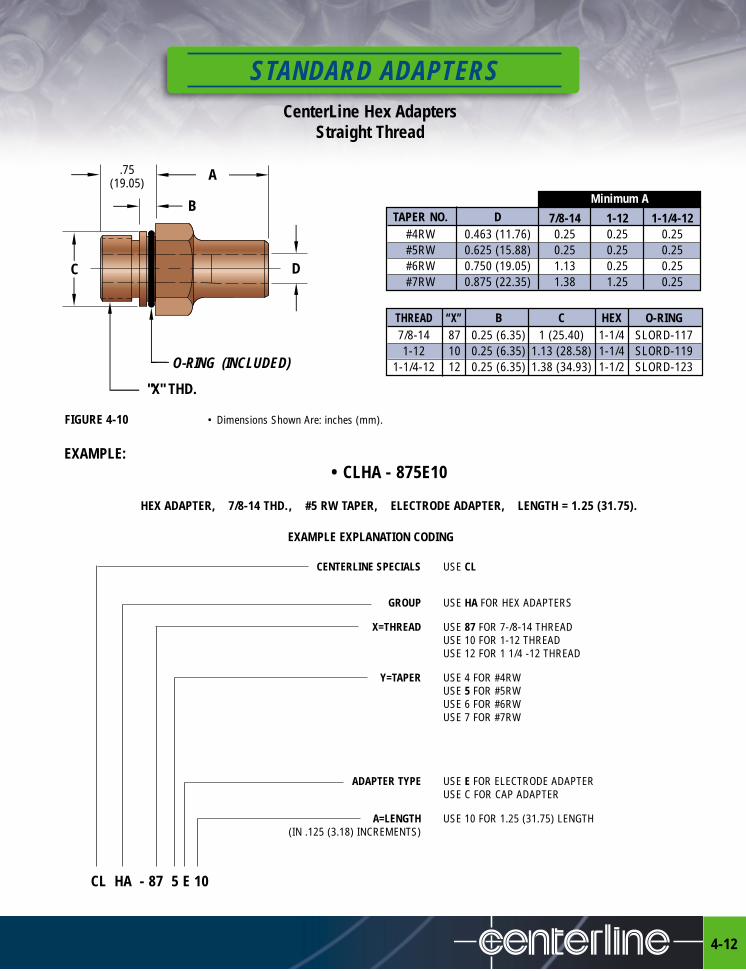
STANDARD ADAPTERSCenterLine Hex Adapters
Straight Thread
4-12
FIGURE 4-10 • Dimensions Shown Are: inches (mm).
EXAMPLE:• CLHA - 875E10
HEX ADAPTER, 7/8-14 THD., #5 RW TAPER, ELECTRODE ADAPTER, LENGTH = 1.25 (31.75).
O-RING (INCLUDED)
.75(19.05)
A
B
C D
"X" THD.
THREAD “X” B C HEX O-RING7/8-14 87 0.25 (6.35) 1 (25.40) 1-1/4 SLORD-1171-12 10 0.25 (6.35) 1.13 (28.58) 1-1/4 SLORD-119
1-1/4-12 12 0.25 (6.35) 1.38 (34.93) 1-1/2 SLORD-123
EXAMPLE EXPLANATION CODING
CENTERLINE SPECIALS USE CL
GROUP USE HA FOR HEX ADAPTERS
X=THREAD USE 87 FOR 7-/8-14 THREADUSE 10 FOR 1-12 THREADUSE 12 FOR 1 1/4 -12 THREAD
Y=TAPER USE 4 FOR #4RWUSE 5 FOR #5RWUSE 6 FOR #6RWUSE 7 FOR #7RW
ADAPTER TYPE USE E FOR ELECTRODE ADAPTERUSE C FOR CAP ADAPTER
A=LENGTH USE 10 FOR 1.25 (31.75) LENGTH(IN .125 (3.18) INCREMENTS)
CL HA - 87 5 E 10
Minimum ATAPER NO. D 7/8-14 1-12 1-1/4-12
#4RW 0.463 (11.76) 0.25 0.25 0.25#5RW 0.625 (15.88) 0.25 0.25 0.25#6RW 0.750 (19.05) 1.13 0.25 0.25#7RW 0.875 (22.35) 1.38 1.25 0.25

Cap and Electrode Hex Adapters Pipe Thread
STANDARD ADAPTERS
4-13
ELECTRODE CODE 4 5 4 5 5 6 7A– DIAMETER 0.88 (22.35) 0.94 (23.88) 0.88 (22.35) 0.94 (23.88) 0.94 (23.88) 1.09 (27.69) 1.24 (31.50)B– LENGTH AS CODEDA– LENGTH (Minimum) 0.88 (22.35) 0.88 (22.35) 1.00 (25.40) 1.00 (25.40) 1.12 (28.45) 1.12 (28.45) 1.38 (35.05)C– HOLE DIAMETER 0.42 (10.67) 0.44 (11.18) 0.42 (10.67) 0.44 (11.18) 0.44 (11.18) 0.50 (12.70) 0.56 (14.22)D– TAPER DIAMETER 0.463 (11.76) 0.625 (15.88) 0.463 (15.88) 0.625 (15.88) 0.625 (15.88) 0.750 (19.05) 0.875 (22.22)E– HEX LENGTH 0.88 (22.35) 0.88 (22.35) 1.00 (25.40) 1.00 (25.40) 1.38 (35.05) 1.38 (35.05) 1.38 (35.05)F– THREAD LENGTH 0.62 (15.75) 0.62 (15.75) 0.75 (19.05) 0.75 (19.05) 0.88 (22.35) 0.88 (22.35) 0.88 (22.35)G– HEX 1.00 (25.40) 1.00 (25.40) 1.00 (25.40) 1.00 (25.40) 1.25 (31.75) 1.25 (31.75) 1.25 (31.75)H– THREAD (N.P.T.) 1/2 1/2 5/8 5/8 3/4 3/4 3/4
D
A
C
F
E
B
H G
FIGURE 4-11 (Material RWMA Class 2 & 3)
• TO ORDER YOUR SPECIALS USE CODING CHART - SEE PG. 4-14
CAP ADAPTER CHART
ELECTRODE ADAPTER CHART
• Dimensions Shown Are: inches (mm).• See Pg. 3-2 For Caps.
ELECTRODE CODE 4 5 4 5 5 6 6-1 7A– DIAMETER 0.50 (12.70) 0.62 (15.75) 0.50 (12.70) 0.62 (15.75) 0.62 (15.75) 0.75 (19.05) 0.75 (19.05) 0.88 (22.35)
B– LENGTH AS CODEDA– LENGTH (Minimum) 0.88 (22.35) 0.88 (22.35) 1.00 (25.40) 1.00 (25.40) 1.12 (28.45) 1.12 (28.45) 1.12 (28.45) 1.12 (28.45)
C– HOLE DIAMETER 0.28 (7.11) 0.38 (9.65) 0.28 (7.11) 0.38 (9.65) 0.38 (9.65) 0.44 (11.18) 0.44 (11.18) 0.56 (14.22)
D– TAPER DIAMETER 0.313 (7.95) 0.414 (10.52) 0.313 (7.95) 0.414 (10.52) 0.414 (10.52) 0.500 (12.70) 0.562 (14.27) 0.700 (17.78)
E– HEX LENGTH 0.88 (22.35) 0.88 (22.35) 1.00 (25.40) 1.00 (25.40) 1.38 (35.05) 1.38 (35.05) 1.38 (35.05) 1.38 (35.05)
F– THREAD LENGTH 0.62 (15.75) 0.62 (15.75) 0.75 (19.05) 0.75 (19.05) 0.88 (22.35) 0.88 (22.35) 0.88 (22.35) 0.88 (22.35)
G– HEX 1.00 (25.40) 1.00 (25.40) 1.00 (25.40) 1.00 (25.40) 1.25 (31.75) 1.25 (31.75) 1.25 (31.75) 1.25 (31.75)
H– THREAD (N.P.T.) 1/2 1/2 5/8 5/8 3/4 3/4 3/4 3/4
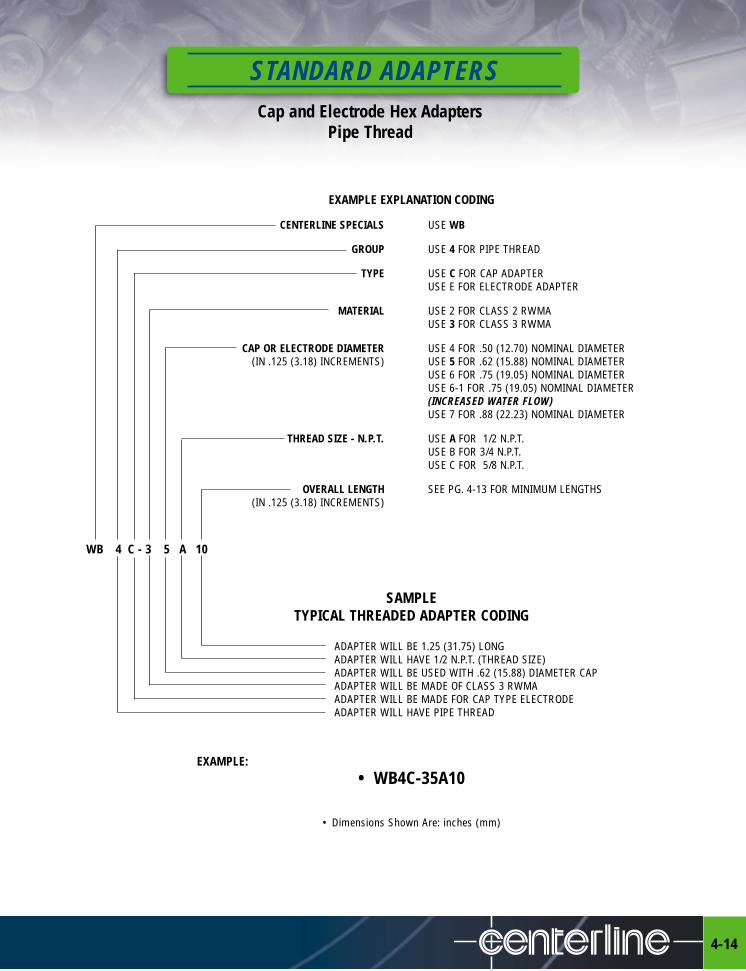
STANDARD ADAPTERSCap and Electrode Hex Adapters
Pipe Thread
4-14
EXAMPLE EXPLANATION CODING
CENTERLINE SPECIALS USE WB
GROUP USE 4 FOR PIPE THREAD
TYPE USE C FOR CAP ADAPTERUSE E FOR ELECTRODE ADAPTER
MATERIAL USE 2 FOR CLASS 2 RWMAUSE 3 FOR CLASS 3 RWMA
CAP OR ELECTRODE DIAMETER USE 4 FOR .50 (12.70) NOMINAL DIAMETER(IN .125 (3.18) INCREMENTS) USE 5 FOR .62 (15.88) NOMINAL DIAMETER
USE 6 FOR .75 (19.05) NOMINAL DIAMETERUSE 6-1 FOR .75 (19.05) NOMINAL DIAMETER(INCREASED WATER FLOW)USE 7 FOR .88 (22.23) NOMINAL DIAMETER
THREAD SIZE - N.P.T. USE A FOR 1/2 N.P.T.USE B FOR 3/4 N.P.T.USE C FOR 5/8 N.P.T.
OVERALL LENGTH SEE PG. 4-13 FOR MINIMUM LENGTHS(IN .125 (3.18) INCREMENTS)
WB 4 C - 3 5 A 10
SAMPLETYPICAL THREADED ADAPTER CODING
ADAPTER WILL BE 1.25 (31.75) LONGADAPTER WILL HAVE 1/2 N.P.T. (THREAD SIZE)ADAPTER WILL BE USED WITH .62 (15.88) DIAMETER CAPADAPTER WILL BE MADE OF CLASS 3 RWMAADAPTER WILL BE MADE FOR CAP TYPE ELECTRODEADAPTER WILL HAVE PIPE THREAD
EXAMPLE:• WB4C-35A10
• Dimensions Shown Are: inches (mm)

RESISTANCE WELDING ELECTRODES
5-1
I20°C°
B
B
D
E
F
G
H A
EXAMPLE EXPLANATION CODING
CENTERLINE SPECIALS USE W FOR TIPS WITH TAPERED SHANKS
NOSE TYPE USE A FOR POINTED NOSEUSE B FOR DOME NOSEUSE C FOR FLAT NOSEUSE D FOR OFFSET NOSEUSE E FOR TRUNCATED NOSEUSE F FOR RADIUS NOSE
MATERIAL USE 2 FOR CLASS 2 RWMA ALLOYUSE 3 FOR CLASS 3 RWMA ALLOYUSE Z FOR ZIRCONIUM
RW TAPER USE 4 FOR 4 RW TAPERUSE 5 FOR 5 RW TAPERUSE 6 FOR 6 RW TAPERUSE 7 FOR 7 RW TAPER
OVERALL LENGTH USE 05 FOR 1.25 (31.75) MINIMUM LENGTH(IN .25 (6.35) INCREMENTS) USE 06 FOR 1.50 (38.10) LENGTH
USE 07 FOR 1.75 (44.45) LENGTHUSE 08 FOR 2.00 (50.80) LENGTHUSE 09 FOR 2.25 (57.15) LENGTHETC.
W A - 2 4 05
SAMPLETYPICAL TIP WITH TAPERED SHANK CODING
TIP OVERALL LENGTH WILL BE 1.25 (31.75)TIP WILL HAVE #4 RWMA TAPERTIP WILL BE MADE OF CLASS 2 RWMATIP WILL HAVE TYPE A NOSE
EXAMPLE:
• WA-2405• Dimensions Shown Are: inches (mm).
• Dimensions Shown Are: inches (mm).“A” POINTED
“B” DOME
“C” FLAT
“D” OFFSET
“E” TRUNCATED
“F” RADIUS
FIGURE 5-1 (Material RWMA Class 2 & 3)
Tips With Tapered ShanksNose Types A, B, C, D, E & F

RESISTANCE WELDING ELECTRODESTips With Tapered Shanks
Nose Types A, B, C, D, E & F
5-2
ITEM NO. DIMENSIONSA B C D E F G H I
CLASS 2 Major Nose Angle Overall RW Water Hole Water Hole Weld Face Nose SphereDiameter Length Offset Length Taper Diameter Depth Diameter Radius
W*-2405 .38 (9.53) 1.25 (31.75) .75 (19.05)W*-2406 .63 (15.88) 1.50 (38.10) 1.00 (25.40)W*-2407 .75 (19.05) 1.75 (44.45) 1.25 (31.75)W*-2408 .75 (19.05) 2.00 (50.80) 1.50 (38.10)W*-2409 .75 (19.05) 2.25 (57.15) 1.75 (44.45)W*-2410 .482 (12.24) .75 (19.05) 30° 2.50 (63.50) 4 .28 (7.14) 2.00 (50.80) .19 (4.76) 2W*-2411 .75 (19.05) 2.75 (69.85) 2.25 (57.15)W*-2412 .75 (19.05) 3.00 (76.20) 2.50 (63.50)W*-2413 .75 (19.05) 3.25 (82.55) 2.75 (69.85)W*-2414 .75 (19.05) 3.50 (88.90) 3.00 (76.20)W*-2415 .75 (19.05) 3.75 (92.25) 3.25 (82.55)W*-2416 .75 (19.05) 4.00 (101.60) 3.50 (88.90)W*-2505 .75 (19.05) 40° 1.25 (31.75) .50 (12.70)W*-2506 .75 (19.05) 40° 1.50 (38.10) .75 (19.05)W*-2507 .75 (19.05) 30° 1.75 (44.45) 1.00 (25.40)W*-2508 1.13 (28.58) 30° 2.00 (50.80) 1.25 (31.75)W*-2509 1.13 (28.58) 30° 2.25 (57.15) 1.50 (38.10)W*-2510 .625 (15.88) 1.13 (28.58) 30° 2.50 (63.50) 5 .38 (9.53) 1.75 (44.45) .25 (6.35) 2W*-2511 1.13 (28.58) 30° 2.75 (69.85) 2.00 (50.80)W*-2512 1.13 (28.58) 30° 3.00 (76.20) 2.25 (57.15)W*-2513 1.13 (28.58) 30° 3.25 (82.55) 2.50 (63.50)W*-2514 1.13 (28.58) 30° 3.50 (88.90) 2.75 (69.85)W*-2515 1.13 (28.58) 30° 3.75 (95.25) 3.00 (76.20)W*-2516 1.13 (28.58) 30° 4.00 (101.60) 3.25 (82.55)W*-2608 1.00 (25.40) 2.00 (50.80) 1.25 (31.75)W*-2610 1.00 (25.40) 2.50 (63.50) 1.75 (44.45)W*-2612 .750 (19.05) 1.00 (25.40) 30° 3.00 (76.20) 6 .44 (11.11) 2.25 (57.15) .28 (7.14) 4W*-2614 1.00 (25.40) 3.50 (88.90) 2.75 (69.85)W*-2616 1.00 (25.40) 4.00 (101.60) 3.25 (82.55)W*-2708 .75(19.05) 40° 2.00 (50.80) 1.25 (31.75)W*-2710 1.13 (28.58) 30° 2.50 (63.50) 1.75 (44.45)W*-2712 .875 (22.23) 1.13 (28.58) 30° 3.00 (76.20) 7 .50 (12.70) 2.25 (57.15) .31 (7.94) 6W*-2714 1.13 (28.58) 30° 3.50 (88.90) 2.75 (69.85)W*-2716 1.13 (28.58) 30° 4.00 (101.60) 3.25 (82.55)Replace*with nose type A, B, C, D, E, or F.
KEY TO ITEM NUMBERS
W - Standard Prefix
* - Nose Designation (see pg. 5-1 for nose types)2, 3 or Z - RWMA Alloy Class4 thru 7 - RW Taper 05 thru 16 - Overall Length – in .25 (6.35) Increments • Dimensions Shown Are: inches (mm).

Double Bend Offset Electrodes
RESISTANCE WELDING ELECTRODES
5-3
EXAMPLE EXPLANATION CODING
CENTERLINE SPECIALS USE W
NOSE TYPE USE A FOR NOSE “A”USE B FOR NOSE “B”USE C FOR NOSE “C”USE D FOR NOSE “D”
GROUP USE O FOR DOUBLE BEND OFFSET ELECTRODE
MATERIAL USE 2 FOR CLASS 2 RWMAUSE 3 FOR CLASS 3 RWMA
RW TAPER USE 4 FOR 4 RW TAPER (.482 (12.24) DIAMETER)USE 5 FOR 5 RW TAPER (.625 (15.88) DIAMETER)
A = OVERALL LENGTH USE 08 FOR 2.00 (50.80) MINIMUM LENGTH(IN .25 (6.35) INCREMENTS)
B = OFFSET LENGTH USE 08 FOR .50 (12.70) MINIMUM OFFSET(IN .06 (1.59) INCREMENTS)
W A O - 2 4 08 08
SAMPLETYPICAL DOUBLE BEND OFFSET CODING
ELECTRODE OFFSET WILL BE .50 (12.70)ELECTRODE WILL BE 2.00 (50.80) LONGELECTRODE WILL HAVE 4 RW TAPERELECTRODE WILL BE MADE OF CLASS 2 RWMA MATERIALDOUBLE BEND OFFSET ELECTRODEELECTRODE NOSE TYPE WILL BE “A” NOSE
• Dimensions Shown Are: inches (mm).
"B" "C" "D"
A
B
"A" NOSE
RW TAPER
1.25(31.75)
WATER TUBE.19 (4.76) TUBE - .48 (12.24) DIA..25 (6.35) TUBE - .62 (15.88) DIA.
Example: • WAO-2408-08
FIGURE 5-2 (Material RWMA Class 2 & 3)

RESISTANCE WELDING ELECTRODESSingle Bend Electrodes
5-4
EXAMPLE EXPLANATION CODING
CENTERLINE SPECIALS USE CL
GROUP USE L FOR SINGLE BEND ELECTRODE
NOSE TYPE USE A FOR NOSE “A”USE B FOR NOSE “B”USE C FOR NOSE “C”USE D FOR NOSE “D”USE E FOR NOSE “E”USE F FOR NOSE “F”
MATERIAL USE 2 FOR CLASS 2 RWMAUSE 3 FOR CLASS 3 RWMAUSE Z FOR ZIRCONIUM
C = ADAPTER DIAMETER USE 5 FOR .62 (15.88) NOMINAL DIAMETER STRAIGHT SHANK(IN .125 (3.18) INCREMENTS) USE 6 FOR .75 (19.05) NOMINAL DIAMETER STRAIGHT SHANK
USE 7 FOR .88 (22.35) NOMINAL DIAMETER STRAIGHT SHANKUSE 5E FOR .62 (15.88) NOMINAL DIAMETER ELECTRODE TAPER SHANKUSE 6E FOR .75 (19.05) NOMINAL DIAMETER ELECTRODE TAPER SHANKUSE 7E FOR .88 (22.35) NOMINAL DIAMETER ELECTRODE TAPER SHANK
A = OVERALL LENGTH USE 10 FOR 2.5 (63.50) MINIMUM LENGTH(IN .25 (6.35) INCREMENTS)
B = OFFSET LENGTH USE 6 FOR .75 (19.05) MINIMUM OFFSET(IN .125 (3.18) INCREMENTS)
D = OFFSET ANGLE USE 30 FOR 30° OFFSETUSE 45 FOR 45° OFFSETUSE 60 FOR 60° OFFSETUSE 75 FOR 75° OFFSETUSE 90 FOR 90° OFFSET
CL L A - 2 5 10 6 90SAMPLE
TYPICAL ELECTRODE CODING
ELECTRODE OFFSET ANGLE WILL BE 90°ELECTRODE OFFSET WILL BE .75 (19.05) LONGELECTRODE WILL BE 2.50 (63.50) LONGELECTRODE WILL HAVE .62 (15.88) DIAMETERELECTRODE WILL BE MADE OF CLASS 2 RWMA MATERIALELECTRODE NOSE TYPE WILL BE TYPE “A”SINGLE BEND ELECTRODE
• Dimensions Shown Are: inches (mm).
"B" "C" "D" "E" "F"A
B D°
C
"A" NOSE
1.25(31.75)
WATER TUBE.25 (6.35) O.D.
Example: • CLLA-25-10690
FIGURE 5-3 (Material RWMA Class 2, 3 & Zirconium)

J Shape Electrodes
RESISTANCE WELDING ELECTRODES
5-5
EXAMPLE EXPLANATION CODINGCENTERLINE SPECIALS USE CL
GROUP USE JE FOR “J” SHAPE ELECTRODE
D = NOSE TYPE USE 1 FOR NOSE - .62 (15.88) DIAMETER “A” NOSEUSE 2 FOR NOSE - .75 (19.05) DIAMETER “A” NOSEUSE 3 FOR NOSE - .88 (22.23) DIAMETER “A” NOSE
MATERIAL USE 2 FOR CLASS 2 RWMAUSE 3 FOR CLASS 3 RWMA
E = ADAPTER DIAMETER USE 5 FOR .62 (15.88) NOMINAL DIAMETER(IN .125 (3.18) INCREMENTS) USE 6 FOR .75 (19.05) NOMINAL DIAMETER
USE 7 FOR .88 (22.23) NOMINAL DIAMETER
A = OVERALL LENGTH USE 10 FOR 2.50 (63.50) MINIMUM LENGTH(IN .25 (6.35) INCREMENTS)
B = OFFSET LENGTH USE 16 FOR 2.00 (50.80) MINIMUM OFFSET(IN .125 (3.18) INCREMENTS)
C = NOSE HEIGHT USE 6 FOR .75 (19.05) MINIMUM HEIGHT(IN .125 (3.18) INCREMENTS)
CL JE 1 - 2 5 - 10 16 6
SAMPLETYPICAL J SHAPE ELECTRODE CODING
ELECTRODE NOSE WILL BE .75 (19.05) HIGHELECTRODE OFFSET WILL BE 2.00 (50.80) LONGELECTRODE WILL BE 2.50 (63.50) LONGELECTRODE WILL HAVE .62 (15.88) DIAMETERELECTRODE WILL BE MADE OF CLASS 2 RWMA MATERIALELECTRODE NOSE TYPE WILL BE .62 (15.88) DIAMETERJ SHAPE ELECTRODE
• Dimensions Shown Are: inches (mm).
A B
D
C
E
1.25(31.75)
WATER TUBE.25 (6.35) O.D.
Example: • CLJE1-25-10166
FIGURE 5-4 (Material RWMA Class 2 & 3)

RESISTANCE WELDING ELECTRODESIrregular-Offset Electrodes With Taper Shanks
5-6
ITEM NO. DIMENSIONSA B C D E
CLASS 2 Major Taper Minor Taper RW Water Hole OffsetDiameter Diameter Taper Diameter Distance
WEF-2412 .463 (11.76) .438 (11.13) 4 .281 (7.14) 1.125 (28.58)WEF-2512 .613 (15.57) .588 (14.94) 5 .375 (9.53) 1.125 (28.58)
1.25 (31.75) Irregular-Offset Electrodes With Taper Shanks
• WFA-SERIES
ITEM NO. DIMENSIONSA B C D E F G H
CLASS 2 Major Nose Overall RW Water Hole Water Hole Minor Taper TaperDiameter Length Length Taper Diameter Depth Diameter Diameter
WFA-2408 .50 (12.70) .38 (9.53) 2.00 (50.80) 4 .281 (7.14) .88 (22.23) .438 (11.13) .463 (11.76)WFA-2409 .50 (12.70) .75 (19.05) 2.38 (60.33) 4 .281 (7.14) .88 (22.23) .438 (11.13) .463 (11.76)WFA-2508 .62 (15.88) .38 (9.53) 2.12 (53.98) 5 .375 (9.53) .75 (19.05) .588 (14.94) .613 (15.58)WFA-2509 .62 (15.88) .75 (19.05) 2.50 (63.50) 5 .375 (9.53) .75 (19.05) .588 (14.94) .613 (15.58)
.75(19.05)
.50(12.70)
3.0(76.20)
E
.37 (9.53) DIA.
A B D
.50(12.70)
1.25(31.75)
.37 (9.53)(WELDING FACE DIAMETER)
.62 (15.88)(WIDTH OF FACE)
H A
B
C
G E
F
D
Spade Electrodes
FIGURE 5-6 (Material RWMA Class 2)
ITEM NO. “A” O.A.L.WEM100-1 3.31 (84.14)WEM100-2 3.56 (90.49)WEM100-3 3.81 (96.84)WEM100-4 4.06 (103.19)
1.50(38.10)
.75(19.05)
.31(7.94)
1.87(47.63)
#5 RW TAPER
A
.38 (9.53) DRILL
FIGURE 5-5 (Material RWMA Class 2)
• Dimensions Shown Are: inches (mm).
• WEF-SERIES
• Dimensions Shown Are: inches (mm).
FIGURE 5-7 (Material RWMA Class 2) • Dimensions Shown Are: inches (mm).
RESISTANCE WELDING ELECTRODES
5-7
O Y DRILL
.03 x 45° CHAMFER TYP.
.25 + F (MIN .37)
Z= X + C
.13
.25 (OPTIONAL CLASS 11 OR 12)
.02 x 45° CHAMFER
.600 TPF MORSE TAPER
R.06
F
CX
O E DRILL O D
O B
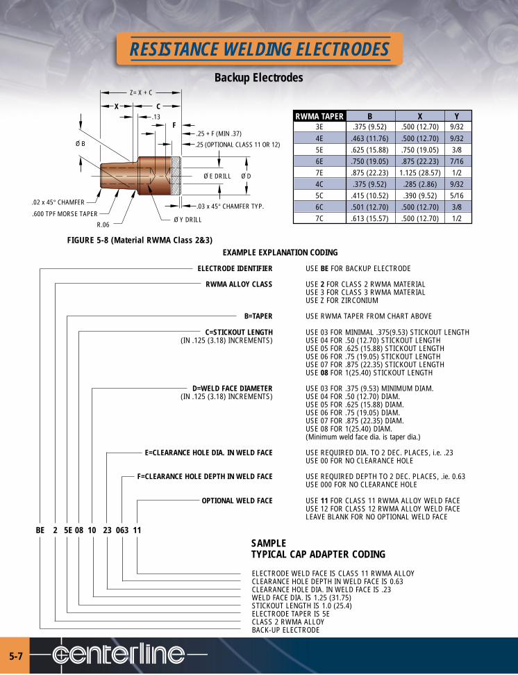
EXAMPLE EXPLANATION CODING
ELECTRODE IDENTIFIER USE BE FOR BACKUP ELECTRODE
RWMA ALLOY CLASS USE 2 FOR CLASS 2 RWMA MATERIALUSE 3 FOR CLASS 3 RWMA MATERIALUSE Z FOR ZIRCONIUM
B=TAPER USE RWMA TAPER FROM CHART ABOVE
C=STICKOUT LENGTH USE 03 FOR MINIMAL .375(9.53) STICKOUT LENGTH(IN .125 (3.18) INCREMENTS) USE 04 FOR .50 (12.70) STICKOUT LENGTH
USE 05 FOR .625 (15.88) STICKOUT LENGTHUSE 06 FOR .75 (19.05) STICKOUT LENGTHUSE 07 FOR .875 (22.35) STICKOUT LENGTHUSE 08 FOR 1(25.40) STICKOUT LENGTH
D=WELD FACE DIAMETER USE 03 FOR .375 (9.53) MINIMUM DIAM.(IN .125 (3.18) INCREMENTS) USE 04 FOR .50 (12.70) DIAM.
USE 05 FOR .625 (15.88) DIAM.USE 06 FOR .75 (19.05) DIAM.USE 07 FOR .875 (22.35) DIAM.USE 08 FOR 1(25.40) DIAM.(Minimum weld face dia. is taper dia.)
E=CLEARANCE HOLE DIA. IN WELD FACE USE REQUIRED DIA. TO 2 DEC. PLACES, i.e. .23USE 00 FOR NO CLEARANCE HOLE
F=CLEARANCE HOLE DEPTH IN WELD FACE USE REQUIRED DEPTH TO 2 DEC. PLACES, .ie. 0.63USE 000 FOR NO CLEARANCE HOLE
OPTIONAL WELD FACE USE 11 FOR CLASS 11 RWMA ALLOY WELD FACEUSE 12 FOR CLASS 12 RWMA ALLOY WELD FACELEAVE BLANK FOR NO OPTIONAL WELD FACE
SAMPLETYPICAL CAP ADAPTER CODING
ELECTRODE WELD FACE IS CLASS 11 RWMA ALLOYCLEARANCE HOLE DEPTH IN WELD FACE IS 0.63CLEARANCE HOLE DIA. IN WELD FACE IS .23WELD FACE DIA. IS 1.25 (31.75)STICKOUT LENGTH IS 1.0 (25.4)ELECTRODE TAPER IS 5ECLASS 2 RWMA ALLOYBACK-UP ELECTRODE
BE 2 5E 08 10 23 063 11
FIGURE 5-8 (Material RWMA Class 2&3)
Backup Electrodes
RWMA TAPER B X Y3E .375 (9.52) .500 (12.70) 9/324E .463 (11.76) .500 (12.70) 9/325E .625 (15.88) .750 (19.05) 3/86E .750 (19.05) .875 (22.23) 7/167E .875 (22.23) 1.125 (28.57) 1/24C .375 (9.52) .285 (2.86) 9/325C .415 (10.52) .390 (9.52) 5/166C .501 (12.70) .500 (12.70) 3/87C .613 (15.57) .500 (12.70) 1/2
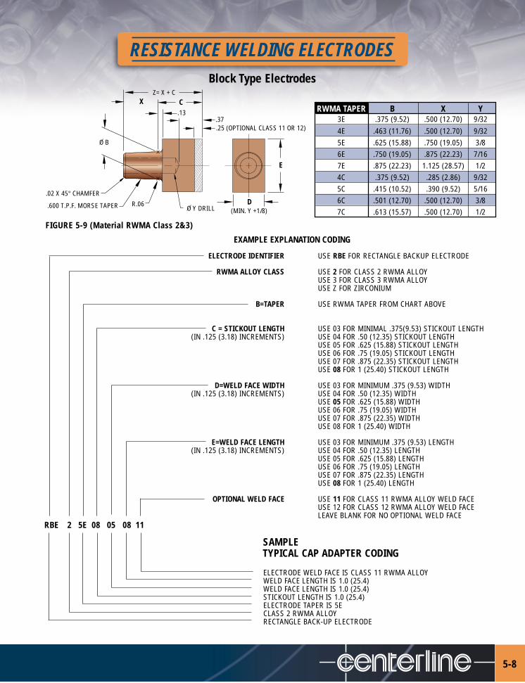
RESISTANCE WELDING ELECTRODESBlock Type Electrodes
5-8
.37.13
.25 (OPTIONAL CLASS 11 OR 12)
(MIN. Y +1/8)R.06.600 T.P.F. MORSE TAPER
.02 X 45° CHAMFER
E
CX
DO Y DRILL
O B
Z= X + C
RWMA TAPER B X Y3E .375 (9.52) .500 (12.70) 9/324E .463 (11.76) .500 (12.70) 9/325E .625 (15.88) .750 (19.05) 3/86E .750 (19.05) .875 (22.23) 7/167E .875 (22.23) 1.125 (28.57) 1/24C .375 (9.52) .285 (2.86) 9/325C .415 (10.52) .390 (9.52) 5/166C .501 (12.70) .500 (12.70) 3/87C .613 (15.57) .500 (12.70) 1/2
EXAMPLE EXPLANATION CODING
ELECTRODE IDENTIFIER USE RBE FOR RECTANGLE BACKUP ELECTRODE
RWMA ALLOY CLASS USE 2 FOR CLASS 2 RWMA ALLOYUSE 3 FOR CLASS 3 RWMA ALLOYUSE Z FOR ZIRCONIUM
B=TAPER USE RWMA TAPER FROM CHART ABOVE
C = STICKOUT LENGTH USE 03 FOR MINIMAL .375(9.53) STICKOUT LENGTH(IN .125 (3.18) INCREMENTS) USE 04 FOR .50 (12.35) STICKOUT LENGTH
USE 05 FOR .625 (15.88) STICKOUT LENGTHUSE 06 FOR .75 (19.05) STICKOUT LENGTHUSE 07 FOR .875 (22.35) STICKOUT LENGTHUSE 08 FOR 1 (25.40) STICKOUT LENGTH
D=WELD FACE WIDTH USE 03 FOR MINIMUM .375 (9.53) WIDTH(IN .125 (3.18) INCREMENTS) USE 04 FOR .50 (12.35) WIDTH
USE 05 FOR .625 (15.88) WIDTHUSE 06 FOR .75 (19.05) WIDTHUSE 07 FOR .875 (22.35) WIDTHUSE 08 FOR 1 (25.40) WIDTH
E=WELD FACE LENGTH USE 03 FOR MINIMUM .375 (9.53) LENGTH(IN .125 (3.18) INCREMENTS) USE 04 FOR .50 (12.35) LENGTH
USE 05 FOR .625 (15.88) LENGTHUSE 06 FOR .75 (19.05) LENGTHUSE 07 FOR .875 (22.35) LENGTHUSE 08 FOR 1 (25.40) LENGTH
OPTIONAL WELD FACE USE 11 FOR CLASS 11 RWMA ALLOY WELD FACEUSE 12 FOR CLASS 12 RWMA ALLOY WELD FACELEAVE BLANK FOR NO OPTIONAL WELD FACE
SAMPLETYPICAL CAP ADAPTER CODING
ELECTRODE WELD FACE IS CLASS 11 RWMA ALLOYWELD FACE LENGTH IS 1.0 (25.4)WELD FACE LENGTH IS 1.0 (25.4)STICKOUT LENGTH IS 1.0 (25.4)ELECTRODE TAPER IS 5ECLASS 2 RWMA ALLOYRECTANGLE BACK-UP ELECTRODE
RBE 2 5E 08 05 08 11
FIGURE 5-9 (Material RWMA Class 2&3)
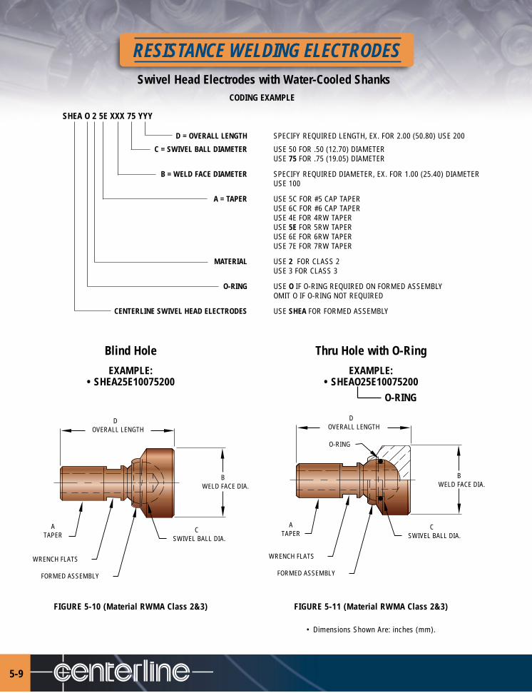
Swivel Head Electrodes with Water-Cooled Shanks
RESISTANCE WELDING ELECTRODES
5-9
CODING EXAMPLE
SHEA O 2 5E XXX 75 YYY
D = OVERALL LENGTH SPECIFY REQUIRED LENGTH, EX. FOR 2.00 (50.80) USE 200
C = SWIVEL BALL DIAMETER USE 50 FOR .50 (12.70) DIAMETERUSE 75 FOR .75 (19.05) DIAMETER
B = WELD FACE DIAMETER SPECIFY REQUIRED DIAMETER, EX. FOR 1.00 (25.40) DIAMETERUSE 100
A = TAPER USE 5C FOR #5 CAP TAPERUSE 6C FOR #6 CAP TAPERUSE 4E FOR 4RW TAPERUSE 5E FOR 5RW TAPERUSE 6E FOR 6RW TAPERUSE 7E FOR 7RW TAPER
MATERIAL USE 2 FOR CLASS 2USE 3 FOR CLASS 3
O-RING USE O IF O-RING REQUIRED ON FORMED ASSEMBLYOMIT O IF O-RING NOT REQUIRED
CENTERLINE SWIVEL HEAD ELECTRODES USE SHEA FOR FORMED ASSEMBLY
Blind Hole Thru Hole with O-Ring
EXAMPLE: EXAMPLE:• SHEA25E10075200 • SHEAO25E10075200
O-RING
FIGURE 5-10 (Material RWMA Class 2&3) FIGURE 5-11 (Material RWMA Class 2&3)
• Dimensions Shown Are: inches (mm).
D OVERALL LENGTH
ATAPER
WRENCH FLATS
FORMED ASSEMBLY
C SWIVEL BALL DIA.
B WELD FACE DIA.
D OVERALL LENGTH
ATAPER
WRENCH FLATS
FORMED ASSEMBLY
C SWIVEL BALL DIA.
B WELD FACE DIA.
O-RING

FIGURE 6-1 (Material RWMA Class 2)
THE CENTERLINE HEAVY DUTY EJECTOR HOLDER HAS BEEN DESIGNED TO PROVIDE LONGER SERVICE LIFE WITH:
• tough RWMA Class 2 alloy barrel • spring-loaded water tube – • leak-proof water seals– resists deformation of the tapered end properly positioned in electrode
automatically
• impact-resistant stainless steel • tested water flow rate of better All CenterLine Holders are constructedejector in a rugged, high-strength than 2.0 gpm at 30 psi. – assures entirely of non-magnetic, corrosion-Bronze Head – for positive ejection adequate cooling of electrode and holder resistant components.
• stainless steel ejector tube
HEAVY DUTY HOLDER REPLACEMENT PARTSA B C 11 12 13 4
Complete RW Taper Barrel Barrel Ejector WaterHolder # Taper Diameter Diameter Length Barrel Tube Tube Head
EAK-40608 4 .463 (11.76) .75 (19.05) 8 RW-2201-4 RW-2301 RW-2401 RW-2101EAK-40708 4 .463 (11.76) .88 (22.35) 8 RW-2202-4 RW-2301 RW-2401 RW-2101EAK-40808 4 .463 (11.76) 1.00 (25.40) 8 RW-2203-4 RW-2301 RW-2401 RW-2101EAK-40812 4 .463 (11.76) 1.00 (25.40) 12 RW-2213-4 RW-2311 RW-2401 RW-2101EAK-41008 4 .463 (11.76) 1.25 (31.75) 8 RW-2204-4 RW-2301 RW-2401 RW-2102EAK-41012 4 .463 (11.76) 1.25 (31.75) 12 RW-2214-4 RW-2311 RW-2401 RW-2102EAK-50808 5 .625 (15.88) 1.00 (25.40) 8 RW-2203-5 RW-2302 RW-2402 RW-2101EAK-50812 5 .625 (15.88) 1.00 (25.40) 12 RW-2213-5 RW-2312 RW-2402 RW-2101EAK-51008 5 .625 (15.88) 1.25 (31.75) 8 RW-2204-5 RW-2302 RW-2402 RW-2102EAK-51012 5 .625 (15.88) 1.25 (31.75) 12 RW-2214-5 RW-2312 RW-2402 RW-2102EAK-51208 5 .625 (15.88) 1.50 (38.10) 8 RW-2205-5 RW-2302 RW-2402 RW-2102EAK-51212 5 .625 (15.88) 1.50 (38.10) 12 RW-2215-5 RW-2312 RW-2402 RW-2102EAK-71208 7 .875 (22.23) 1.50 (38.10) 8 RW-2205-7 RW-2303 RW-2402 RW-2102EAK-71212 7 .875 (22.23) 1.50 (38.10) 12 RW-2215-7 RW-2313 RW-2402 RW-2102
STANDARD REPLACEMENT PARTSDetailNo. Part No. Part Name1 RW-2501 Ejector Pin2 RW-2850 O-Ring – Ejector Pin3 RW-1015 Hose fitting5 RW-2820 Ejector Return Spring6 RW-2601 Retaining Screw7 RW-2810 Retaining Screw Washer8 RW-2860* O-Ring – Barrel (2) Req’d9 RW-2840 Retaining Pin – Ejector Spring10 RW-2830 Water Tube Spring
*SPECIFY O-RING RW-2861 FOR BARRELDIAMETERS OF 1.25 (31.75) AND
1.50 (38.10)–(2 REQ’D)
• Dimensions Shown Are: inches (mm).
C
A B
1
3 6 7 9 10 11 12 13
2 4 5 8
Straight Heavy-Duty Ejector Holders - Swivel head
6-1
HOLDERS
HOLDERS
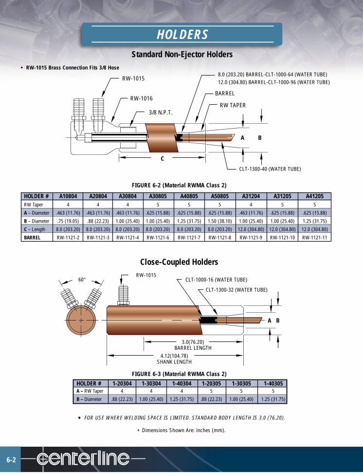
6-2
Standard Non-Ejector Holders• RW-1015 Brass Connection Fits 3/8 Hose
FIGURE 6-2 (Material RWMA Class 2)
HOLDER # A10804 A20804 A30804 A30805 A40805 A50805 A31204 A31205 A41205RW Taper 4 4 4 5 5 5 4 5 5
A – Diameter .463 (11.76) .463 (11.76) .463 (11.76) .625 (15.88) .625 (15.88) .625 (15.88) .463 (11.76) .625 (15.88) .625 (15.88)
B – Diameter .75 (19.05) .88 (22.23) 1.00 (25.40) 1.00 (25.40) 1.25 (31.75) 1.50 (38.10) 1.00 (25.40) 1.00 (25.40) 1.25 (31.75)
C – Length 8.0 (203.20) 8.0 (203.20) 8.0 (203.20) 8.0 (203.20) 8.0 (203.20) 8.0 (203.20) 12.0 (304.80) 12.0 (304.80) 12.0 (304.80)
BARREL RW-1121-2 RW-1121-3 RW-1121-4 RW-1121-6 RW-1121-7 RW-1121-8 RW-1121-9 RW-1121-10 RW-1121-11
Close-Coupled Holders
FIGURE 6-3 (Material RWMA Class 2)
HOLDER # 1-20304 1-30304 1-40304 1-20305 1-30305 1-40305A – RW Taper 4 4 4 5 5 5
B – Diameter .88 (22.23) 1.00 (25.40) 1.25 (31.75) .88 (22.23) 1.00 (25.40) 1.25 (31.75)
• FOR USE WHERE WELDING SPACE IS LIMITED. STANDARD BODY LENGTH IS 3.0 (76.20).
• Dimensions Shown Are: inches (mm).
C
A
RW TAPER
BARREL
8.0 (203.20) BARREL-CLT-1000-64 (WATER TUBE)12.0 (304.80) BARREL-CLT-1000-96 (WATER TUBE)
CLT-1300-40 (WATER TUBE)
RW-1015
RW-1016
3/8 N.P.T.
B
A B
RW-1015CLT-1000-16 (WATER TUBE)
CLT-1300-32 (WATER TUBE)
3.0(76.20)BARREL LENGTH
60°
4.12(104.78)SHANK LENGTH

Offset Non-Ejector Electrode Holders
OFFSET HOLDERS – Ordering Chart90˚ COMPLETE HOLDER NO. B30304 B40304 B30305 B40305RW Electrode Taper 4 4 5 5A – Diameter .463 (11.76) .463 (11.76) .619 (15.72) .619 (15.72)B – Diameter 1.00 (25.40) 1.25 (31.75) 1.00 (25.40) 1.25 (31.75)C – Offset 2.00 (50.80) 2.00 (50.80) 2.00 (50.80) 2.00 (50.80)Body RW-1122-2 RW-1122-3 RW-1122-5 RW-1122-690˚ COMPLETE HOLDER NO. G30304 G40304 G30305 G40305RW Electrode Taper 4 4 5 5A – Diameter .463 (11.76) .463 (11.76) .619 (15.72) .619 (15.72)B – Diameter 1.00 (25.40) 1.25 (31.75) 1.00 (25.40) 1.25 (31.75)C – Offset 3.00 (76.20) 3.00 (76.20) 3.00 (76.20) 3.00 (76.20)Body RW-1126-2 RW-1126-3 RW-1126-5 RW-1126-690˚ COMPLETE HOLDER NO. C30304 C40304 C30305 C40305RW Electrode Taper 4 4 5 5A – Diameter .463 (11.76) .463 (11.76) .619 (15.72) .619 (15.72)B – Diameter 1.00 (25.40) 1.25 (31.75) 1.00 (25.40) 1.25 (31.75)C – Offset 4.00 (101.60) 4.00 (101.60) 4.00 (101.60) 4.00 (101.60)Body RW-1123-2 RW-1123-3 RW-1123-5 RW-1123-630˚ COMPLETE HOLDER NO. D30304 D40304 D30305 D40305RW Electrode Taper 4 4 5 5A – Diameter .463 (11.76) .463 (11.76) .619 (15.72) .619 (15.72)B – Diameter 1.00 (25.40) 1.25 (31.75) 1.00 (25.40) 1.25 (31.75)C – Offset 2.00 (50.80) 2.00 (50.80) 2.00 (50.80) 2.00 (50.80)Body RW-1124-2 RW-1124-3 RW-1124-5 RW-1124-630˚ COMPLETE HOLDER NO. E30304 E40304 E30305 E40305RW Electrode Taper 4 4 5 5A – Diameter .463 (11.76) .463 (11.76) .619 (15.72) .619 (15.72)B – Diameter 1.00 (25.40) 1.25 (31.75) 1.00 (25.40) 1.25 (31.75)C – Offset 3.00 (76.20) 3.00 (76.20) 3.00 (76.20) 3.00 (76.20)Body RW-1127-2 RW-1127-3 RW-1127-5 RW-1127-630˚ COMPLETE HOLDER NO. F30304 F40304 F30305 F40305RW Electrode Taper 4 4 5 5A – Diameter .463 (11.76) .463 (11.76) .619 (15.72) .619 (15.72)B – Diameter 1.00 (25.40) 1.25 (31.75) 1.00 (25.40) 1.25 (31.75)C – Offset 4.00 (101.60) 4.00 (101.60) 4.00 (101.60) 4.00 (101.60)Body RW-1125-2 RW-1125-3 RW-1125-5 RW-1125-6
90˚ HEAD
30˚ HEAD
Ejector typealso available.
• Dimensions Shown Are: inches (mm).
4.75(120.65)
3.0(76.20)
1.62(41.28)
1.62(41.28)
RW-1015
RW-1025 (WATER TUBE)
BODY
CB
AA
FIGURE 6-4 (Material RWMA Class 3)
HOLDERS
6-3

HOLDERS
6-4
Paddle Type Holders - Type 1, 2 & 3
C* XFor these thread/taper types Replace “X” with
1/2 Pipe Thread 50P5/8 Pipe Thread 62P3/4 Pipe Thread 75P7/8-14 Straight Thread 87S1-12 Straight Thread 10S4RW Taper 4E5RW Taper 5E6RW Taper 6E7RW Taper 7E*Other threads/tapers available upon request
ITEM NO. - CLP -
FIGURE 6-5 (Material RWMA Class 2 & 3)• FINAL FIGURE USED IN ORDERING –
• Indicate Desired Shank Diameter “A” - In .125 (3.18) Increments• Indicate Desired Offset Dimension “B” - In .250 (6.35) Increments• For Holders & Tips Specify RWMA Class 2 Or 3 Requirements
EXAMPLE:HOLDER, RWMA CLASS 2, TYPE - 3, “A” = 1.00 (25.40) DIAMETER, “B” = 4.00 (101.60) OFFSET.
CLP- 2 3- 8 16
Item No.“B” Dimension
RWMA “A” DiameterAlloy Class Type
Platen Mount - Holders
SAMPLE TIPS:
TYPE-1 – XC-2998• See Pg. 3-3 For Caps.
TYPE-2 – CL-78-50C• See Pg. 3-4 For Caps.
TYPE-3 – CLPC-2998• See Pg. 3-3 For Caps.
See pages 4-12 & 4-13for Adapters.
DIM. CL-1-PM-”X” CL-2-PM- “X”A 4.75 (120.65) 7.00 (177.80)B 2.75 (69.85) 4.31 (109.47)
SHANKLENGTH
3.0 (76.20)
.50 (12.70)
#RW1015A
B
2.00 2.00
1.00
1.00
1.75 B A
.75
.06x45°
1/4NPT
2 PLCS
*C 5/16-32 THD
.56
FIGURE 6-6 (Material RWMA Class 2)
See pages 9-1 & 9-2for Water Tubes.
Cylinder Mounted Holders
HOLDERS
6-5
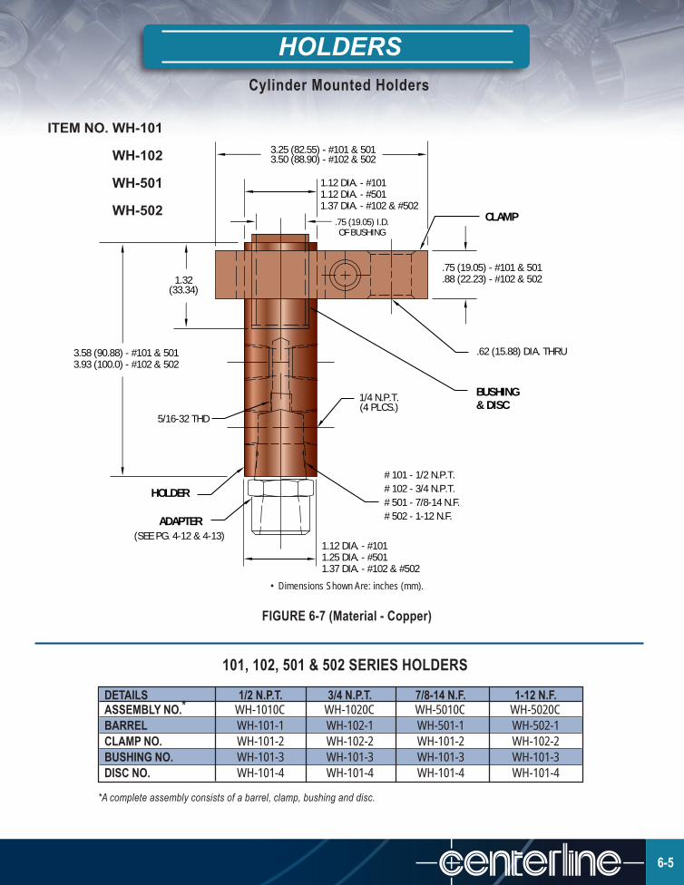
ITEM NO. WH-101
WH-102
WH-501
WH-502
DETAILS 1/2 N.P.T. 3/4 N.P.T. 7/8-14 N.F. 1-12 N.F.ASSEMBLY NO.* WH-1010C WH-1020C WH-5010C WH-5020CBARREL WH-101-1 WH-102-1 WH-501-1 WH-502-1CLAMP NO. WH-101-2 WH-102-2 WH-101-2 WH-102-2BUSHING NO. WH-101-3 WH-101-3 WH-101-3 WH-101-3DISC NO. WH-101-4 WH-101-4 WH-101-4 WH-101-4
3.25 (82.55) - #101 & 5013.50 (88.90) - #102 & 502
CLAMP.75 (19.05) I.D.OF BUSHING
.75 (19.05) - #101 & 501
.88 (22.23) - #102 & 502
.62 (15.88) DIA. THRU
1/4 N.P.T.(4 PLCS.)
# 101 - 1/2 N.P.T.# 102 - 3/4 N.P.T.# 501 - 7/8-14 N.F.# 502 - 1-12 N.F.
(SEE PG. 4-12 & 4-13)
5/16-32 THD
3.58 (90.88) - #101 & 5013.93 (100.0) - #102 & 502
1.32(33.34)
BUSHING& DISC
HOLDER
ADAPTER
1.12 DIA. - #1011.12 DIA. - #5011.37 DIA. - #102 & #502
1.12 DIA. - #1011.25 DIA. - #5011.37 DIA. - #102 & #502
*A complete assembly consists of a barrel, clamp, bushing and disc.
• Dimensions Shown Are: inches (mm).
FIGURE 6-7 (Material - Copper)
101, 102, 501 & 502 SERIES HOLDERS

HOLDERS
6-6
Cylinder Mounted Holders
EXAMPLE EXPLANATION CODING
CENTERLINE BARRELS USE WHCL
OFFSET USE O FOR OFFSET BARRELSOMIT FOR STRAIGHT BARRELS
X =THREAD USE 50P FOR .500 PIPE THREADUSE 62P FOR .625 PIPE THREADUSE 75P FOR .750 PIPE THREADUSE 87S FOR .875 STRAIGHT THREADUSE 10S FOR 1.00 STRAIGHT THREAD
Y=SHANK USE 112 FOR 1-1/8 DIAMETERUSE 125 FOR 1-1/4 DIAMETERUSE 137 FOR 1-3/8 DIAMETER
OFFSET USE 1 FOR 1/8 OFFSET (MINIMUM)(IN .125 (3.18) INCREMENTS) USE 2 FOR 1/4 OFFSET
USE 3 FOR 3/8 OFFSETUSE 4 FOR 1/2 OFFSETUSE 5 FOR 5/8 OFFSETUSE 6 FOR 3/4 OFFSETUSE 7 FOR 7/8 OFFSETUSE 8 FOR 1” OFFSET (MAXIMUM)
OUT
1/4-18 NPT2 PLACES
3.50 (88.90)3.50 (88.90)
THD.X
1/8-27 NPT2 PLACES
IN OUT
INSUL. BUSHING#WH-101-3
INSUL. DISC#WH-101-4
5/16-32 THD.
1.201.25ROD
ENGAGEMENT
.75I.D.SHANK DIA.
Y OFFSET
X THD.IN
INSUL. BUSHING#WH-101-3
INSUL. DISC#WH-101-4
5/16-32 THD.
1.371.25ROD
ENGAGEMENT
1.31
.75I.D.SHANK DIA.
Y
FIGURE 6-8 (Material RWMA Class 2)Straight Barrel (WHCL Series)
FIGURE 6-9 (Material RWMA Class 3)Offset Barrel (WHCLO Series)
WHCL O 87S 112 8

HOLDERSHeavy Duty Cylinder Mounted Holders
EXAMPLE EXPLANATION CODING
CENTERLINE HEAVY DUTY BARREL USE WHCLH
OFFSET USE O FOR OFFSET BARRELSOMIT FOR STRAIGHT BARRELS
X=THREAD USE 50P FOR .500 PIPE THREADUSE 62P FOR .625 PIPE THREADUSE 75P FOR .750 PIPE THREADUSE 87S FOR .875 STRAIGHT THREADUSE 10S FOR 1.00 STRAIGHT THREADUSE 12S FOR 1.25 STRAIGHT THREAD
Y=SHANK USE 162 FOR 1-5/8 DIAMETER
OFFSET DISTANCE USE 1 FOR 1/8 OFFSET (MINIMUM)USE 2 FOR 1/4 OFFSETUSE 3 FOR 3/8 OFFSETUSE 4 FOR 1/2 OFFSETUSE 5 FOR 5/8 OFFSETUSE 6 FOR 3/4 OFFSETUSE 7 FOR 7/8 OFFSETUSE 8 FOR 1” OFFSET (MAXIMUM)
FIGURE 6-10 (Material RWMA Class 2)HEAVY DUTY STRAIGHT BARREL
(WHCLH Series)
WHCLH O 87S 162 8
FIGURE 6-11 (Material RWMA Class 3)HEAVY DUTY OFFSET BARREL
(WHCLHO Series)
1.38
4.13
OFFSET
4.06
1.43 1.56
1/4-18 NPT2 PLACES
OUTIN X THD.
5/16-32 THD.5/16-32 THD.
INSUL. DISC#WADSMS112062
INSUL. BUSHING#BUMCS100112143SP 1/4-18 NPT
6 PLACES
OUTIN
X THD.
Y
1.38
1.00I.D.
1.38
SHANK DIA.1.00I.D.SHANK DIA.
Y
RODENGAGEMENT
1.38ROD
ENGAGEMENT
INSUL. DISC#WADSMS112062
INSUL. BUSHING#BUMCS100112143SP
6-7
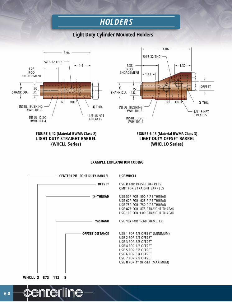
HOLDERSLight Duty Cylinder Mounted Holders
EXAMPLE EXPLANATION CODING
CENTERLINE LIGHT DUTY BARREL USE WHCLL
OFFSET USE O FOR OFFSET BARRELSOMIT FOR STRAIGHT BARRELS
X=THREAD USE 50P FOR .500 PIPE THREADUSE 62P FOR .625 PIPE THREADUSE 75P FOR .750 PIPE THREADUSE 87S FOR .875 STRAIGHT THREADUSE 10S FOR 1.00 STRAIGHT THREAD
Y=SHANK USE 137 FOR 1-3/8 DIAMETER
OFFSET DISTANCE USE 1 FOR 1/8 OFFSET (MINIMUM)USE 2 FOR 1/4 OFFSETUSE 3 FOR 3/8 OFFSETUSE 4 FOR 1/2 OFFSETUSE 5 FOR 5/8 OFFSETUSE 6 FOR 3/4 OFFSETUSE 7 FOR 7/8 OFFSETUSE 8 FOR 1” OFFSET (MAXIMUM)
FIGURE 6-12 (Material RWMA Class 2)LIGHT DUTY STRAIGHT BARREL
(WHCLL Series)
WHCLL O 87S 112 8
FIGURE 6-13 (Material RWMA Class 3)LIGHT DUTY OFFSET BARREL
(WHCLLO Series)
5/16-32 THD.
4.06
1.13
5/16-32 THD.
3.94
INSUL. BUSHING#WH-101-3
INSUL. DISC#WH-101-4
RODENGAGEMENT
1.25
.75I.D.SHANK DIA.
Y
IN OUTX
1/4-18 NPT4 PLACES
THD.
1.41ROD
ENGAGEMENT
.75I.D.
1.38
YSHANK DIA.
1.37
THD.
OFFSET
XIN OUT
1/4-18 NPT6 PLACES
INSUL. DISC#WH-101-4
INSUL. BUSHING#WH-101-3
6-8

HOLDERS
6-9
EXAMPLE EXPLANATION CODING
CENTERLINE CABLE/SHUNT CLAMPS USE WHCLSA FOR SHUNT CLAMPSUSE WHCLCA FOR CABLE CLAMPS
Y = SHANK DIAMETER USE 112 FOR 1.125 DIAMETERUSE 125 FOR 1.250 DIAMETERUSE 137 FOR 1.375 DIAMETER
B = LENGTH USE 0250 FOR 2.50 LENGTH (MIN. FOR WHCLSA)USE 0362 FOR 3.62 LENGTH (MIN. FOR WHCLCA)etc.WHCLSA 112 0250
1.00(25.40)
B2.50 (63.50)
MIN. LENGTHSHUNT CLAMP
5/16-18 TAP.88 (22.23) CENTER
1/2-13 TAP
YSHANK
DIAMETER
1.25(31.75)
KNURLED NUT#4130-481-00
5/16-18S.H.C.S.
B3.62 (91.95)
MIN. LENGTHCABLE CLAMP
Light Duty Shunt/Cable Clamps
Heavy Duty Shunt/Cable Clamps
FIGURE 6-14
EXAMPLE EXPLANATION CODING
CENTERLINE HEAVY DUTY CABLE/SHUNT CLAMPS USE WHCLHSA FOR SHUNT CLAMPSUSE WHCLHCA FOR CABLE CLAMPS
Y = SHANK DIAMETER USE 162 FOR 1.625 DIAMETER
B = LENGTH USE 0325 FOR 3.25 LENGTH (MIN. FOR WHCLHSA)USE 0412 FOR 4.12 LENGTH (MIN. FOR WHCLHCA)etc.WHCLHCA 162 0412
1.25
1.00
2.00
YSHANK
DIAMETER
3.25B
MIN. LENGTHSHUNT CLAMPMIN. LENGTH
CABLE CLAMP
4.12B
2.001.50CENT.
.88CENT.
KNURLED #4130-481-00
5/16-18S.H.C.S. (2)
1.50
1/2-13 TAP
1.25
5/16-18 TAP2 HOLES
(2)
1.501.50
.69
CABLE CLAMP SHUNT CLAMP
FIGURE 6-15
SHUNT CLAMP CABLE CLAMP
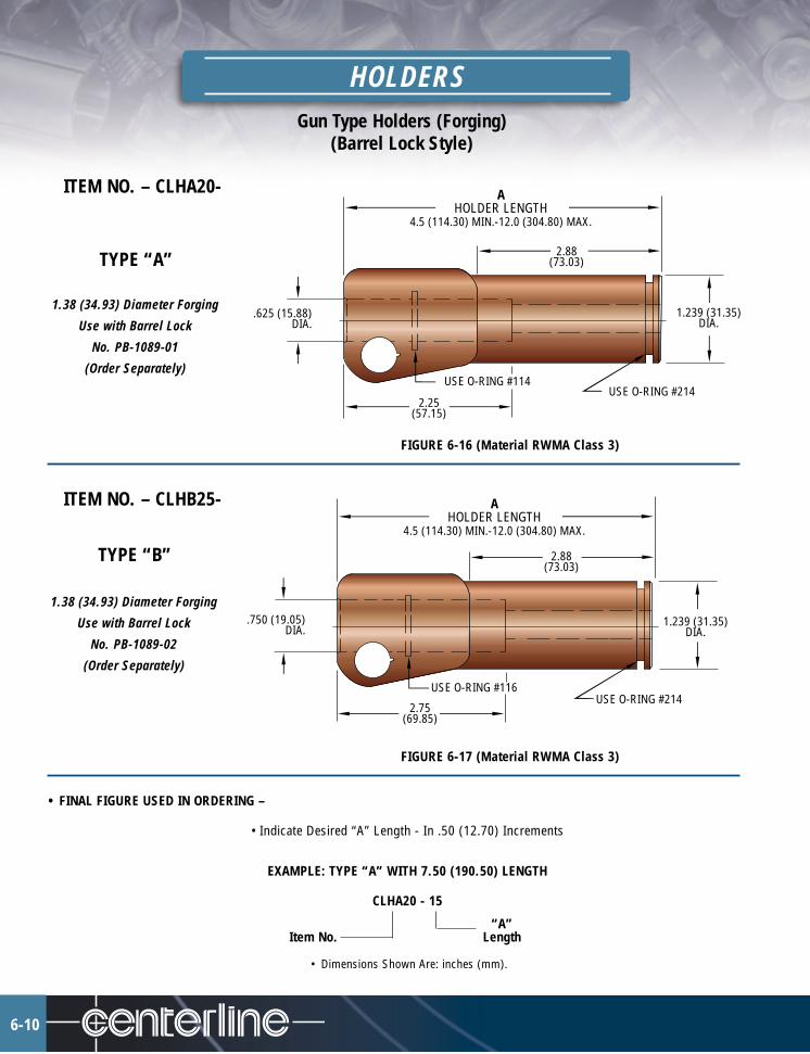
Gun Type Holders (Forging)(Barrel Lock Style)
HOLDERS
6-10
ITEM NO. – CLHA20-
TYPE “A”
1.38 (34.93) Diameter Forging
Use with Barrel Lock
No. PB-1089-01
(Order Separately)
FIGURE 6-16 (Material RWMA Class 3)
ITEM NO. – CLHB25-
TYPE “B”
1.38 (34.93) Diameter Forging
Use with Barrel Lock
No. PB-1089-02
(Order Separately)
FIGURE 6-17 (Material RWMA Class 3)
• FINAL FIGURE USED IN ORDERING –
• Indicate Desired “A” Length - In .50 (12.70) Increments
EXAMPLE: TYPE “A” WITH 7.50 (190.50) LENGTH
CLHA20 - 15
“A”Item No. Length
• Dimensions Shown Are: inches (mm).
AHOLDER LENGTH
4.5 (114.30) MIN.-12.0 (304.80) MAX.
2.88(73.03)
1.239 (31.35)DIA.
USE O-RING #214USE O-RING #114
.625 (15.88)DIA.
AHOLDER LENGTH
4.5 (114.30) MIN.-12.0 (304.80) MAX.
2.88(73.03)
1.239 (31.35)DIA.
USE O-RING #214USE O-RING #116
.750 (19.05)DIA.
2.25(57.15)
2.75(69.85)

ITEM NO. – CLHC30-
TYPE “C”
1.63 (41.28) Diameter Forging
Use with Barrel Lock
No. PB-1089-04
(Order Separately)
FIGURE 6-18 (Material RWMA Class 3)
ITEM NO. – CLHD35-
TYPE “D”
1.63 (41.28) Diameter Forging
Use with Barrel Lock
No. PB-1089-04
(Order Separately)
FIGURE 6-19 (Material RWMA Class 3)
• FINAL FIGURE USED IN ORDERING –
• Indicate Desired Holder Length “A” - In .50 (12.70) Increments
EXAMPLE: TYPE “C” WITH 14.00 (355.60) LENGTH
CLHC30 - 28“A”
Item No. Length
• Dimensions Shown Are: inches (mm).
AHOLDER LENGTH
5.0 (127.00) MIN.-15.0 (381.00) MAX.
2.88 (73.03)
1.239 (31.35)DIA.
USE O-RING #214USE O-RING #118
.875 (22.23)DIA.
2.75(69.85)
AHOLDER LENGTH
6.0 (152.40) MIN.-16.0 (406.40) MAX.
3.38 (85.73)
1.489 (37.70)DIA.
USE O-RING #218USE O-RING #118
.875 (22.23)DIA.
2.75(69.85)
HOLDERSGun Type Holders (Forging)
(Barrel Lock Style)
6-11

Gun Type Holders (Forging)(Barrel Lock Style)
HOLDERS
6-12
ITEM NO. – CLHE40-
TYPE “E”
Use with Barrel Lock Ass’y
No. PB-1089-02
(Order Separately)
FIGURE 6-20 (Material RWMA Class 3)
ITEM NO. – CLHF45-
TYPE “F”
Use with Barrel Lock Ass’y
No. PB-1089-04
(Order Separately)
FIGURE 6-21 (Material RWMA Class 3)
• FINAL FIGURE USED IN ORDERING –
• Indicate Desired Holder Length “A” - In .50 (12.70) Increments• Indicate Desired Offset Dimension “B” - In .25 (6.35) Increments
EXAMPLE: TYPE “E”, “A” = 6.00 (152.40) LENGTH, “B” = 2.50 (63.50), “S” LUG POSITION.
CLHE40 - 12 - 10 - SItem No. Lug
“A” “B”
• Dimensions Shown Are: inches (mm).
90°
AHOLDER LENGTH
4.0 (101.60) MIN. -7.0 (177.80) MAX.
"S" AS SHOWN VIEW "A"
.750 (19.05) DIA.
USE O-RING #116
5/16-32 THD.
2.88(73.03)
USE O-RING #214
1.239 (31.35)DIA.
B
90°
AHOLDER LENGTH
4.0 (101.60) MIN. -7.0 (177.80) MAX.
"S" AS SHOWN
VIEW "A"
.875 (22.23) DIA.
USE O-RING #118
5/16-32 THD.
2.88(73.03)
USE O-RING #218
1.239 (31.35)DIA.
B
W
E
NS
LUG POSITIONSVIEW “A”
W
E
NS
LUG POSITIONSVIEW “A”

ITEM NO. – CLHG50-
TYPE “G”
1.38 (34.93) Diameter Forging
Use with Barrel Lock
No. PB-1089-01
(Order Separately)
FIGURE 6-22 (Material RWMA Class 3)
ITEM NO. – CLHH55-
TYPE “H”
1.38 (34.93) Diameter Forging
Use with Barrel Lock
No. PB-1089-02
(Order Separately)
FIGURE 6-23 (Material RWMA Class 3)
• FINAL FIGURE USED IN ORDERING –• Indicate Desired Holder Length “A” - In .50 (12.70) Increments• Indicate Desired Offset Dimension “B” - In .25 (6.35) Increments
EXAMPLE: TYPE “G”, “A” = 11.00 (279.40) LENGTH, “B” = 5.00 (127.00), “N” LUG POSITION.
CLHG50 - 22 - 20 - NItem No. Lug
“A” “B”
• Dimensions Shown Are: inches (mm).
AHOLDER LENGTH
4.0 (101.60)MIN. -12.0 (304.80)MAX.
1.239 (31.35)DIA.
.625 (15.88) DIA.
90°
"N" AS SHOWN
USE O-RING #114
USE O-RING #2145/16-32 THD.
B
1.239 (31.35)DIA.
.750 (19.05) DIA.
90°
"N" AS SHOWN
USE O-RING #116
USE O-RING #214
5/16-32 THD.
AHOLDER LENGTH
4.0 (101.60)MIN. -12.0 (304.80)MAX.
B
VIEW "A"
VIEW "A"
HOLDERSGun Type Holders (Forging)
(Barrel Lock Style)
6-13
W
E
NS
LUG POSITIONSVIEW “A”
W
E
NS
LUG POSITIONSVIEW “A”
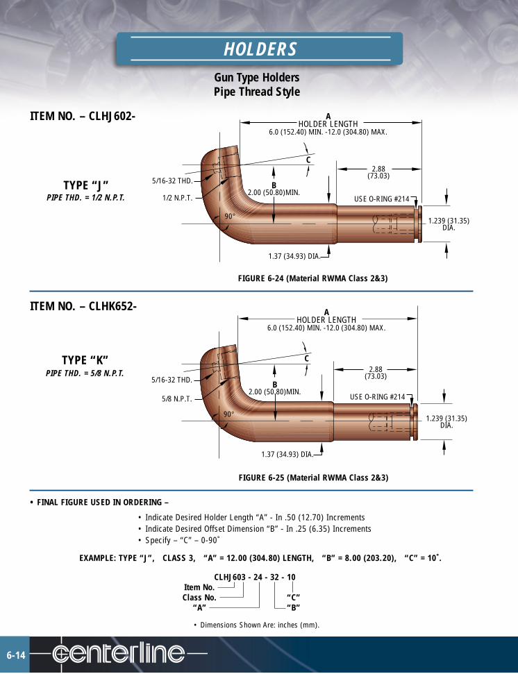
Gun Type HoldersPipe Thread Style
HOLDERS
6-14
ITEM NO. – CLHJ602-
TYPE “J”PIPE THD. = 1/2 N.P.T.
FIGURE 6-24 (Material RWMA Class 2&3)
ITEM NO. – CLHK652-
TYPE “K”PIPE THD. = 5/8 N.P.T.
FIGURE 6-25 (Material RWMA Class 2&3)
• FINAL FIGURE USED IN ORDERING –
• Indicate Desired Holder Length “A” - In .50 (12.70) Increments• Indicate Desired Offset Dimension “B” - In .25 (6.35) Increments• Specify – “C” – 0-90˚
EXAMPLE: TYPE “J”, CLASS 3, “A” = 12.00 (304.80) LENGTH, “B” = 8.00 (203.20), “C” = 10˚.
CLHJ603 - 24 - 32 - 10Item No.Class No. “C”
“A” “B”
• Dimensions Shown Are: inches (mm).
1.239 (31.35)DIA.
1.37 (34.93) DIA.
5/16-32 THD.
1/2 N.P.T. USE O-RING #214
2.88(73.03)
90°
B2.00 (50.80)MIN.
C
AHOLDER LENGTH
6.0 (152.40) MIN. -12.0 (304.80) MAX.
1.239 (31.35)DIA.
1.37 (34.93) DIA.
5/16-32 THD.
5/8 N.P.T.
2.88(73.03)
90°
B2.00 (50.80)MIN.
C
AHOLDER LENGTH
6.0 (152.40) MIN. -12.0 (304.80) MAX.
USE O-RING #214

ITEM NO. – CLHL702-
TYPE “L”PIPE THD. = 3/4 N.P.T.
FIGURE 6-26 (Material RWMA Class 2&3)
ITEM NO. – CLHM752-
TYPE “M”PIPE THD. = 1 N.P.T.
FIGURE 6-27 (Material RWMA Class 2&3)
• FINAL FIGURE USED IN ORDERING –
• Indicate Desired Holder Length “A” - In .50 (12.70) Increments• Indicate Desired Offset Dimension “B” - In .25 (6.35) Increments• Specify – “C” – 0-90˚
EXAMPLE: TYPE “L”, CLASS 2, “A” = 5.50 (139.70) LENGTH, “B” = 7.00 (177.80), “C” = 10˚.
CLHL702 - 11 - 28 - 10Item No.Class No. “C”
“A” “B”
• Dimensions Shown Are: inches (mm).
1.75 (44.45) DIA.
1.489 (37.70)DIA.
5/16-32 THD.
3/4 N.P.T.3.38
(85.73)
90°
B3.00 (76.20)
MIN.
C
AHOLDER LENGTH
5.5 (139.70) MIN. -10.0 (254.00) MAX.
USE O-RING #218
1.489 (37.70)DIA.
1.75 (44.45) DIA.
5/16-32 THD.
1 N.P.T.3.38
(85.73)
90°
B3.00 (76.20)
MIN.
C
AHOLDER LENGTH
5.5 (139.70) MIN. -10.0 (254.00) MAX.
USE O-RING #218
HOLDERSGun Type HoldersPipe Thread Style
6-15
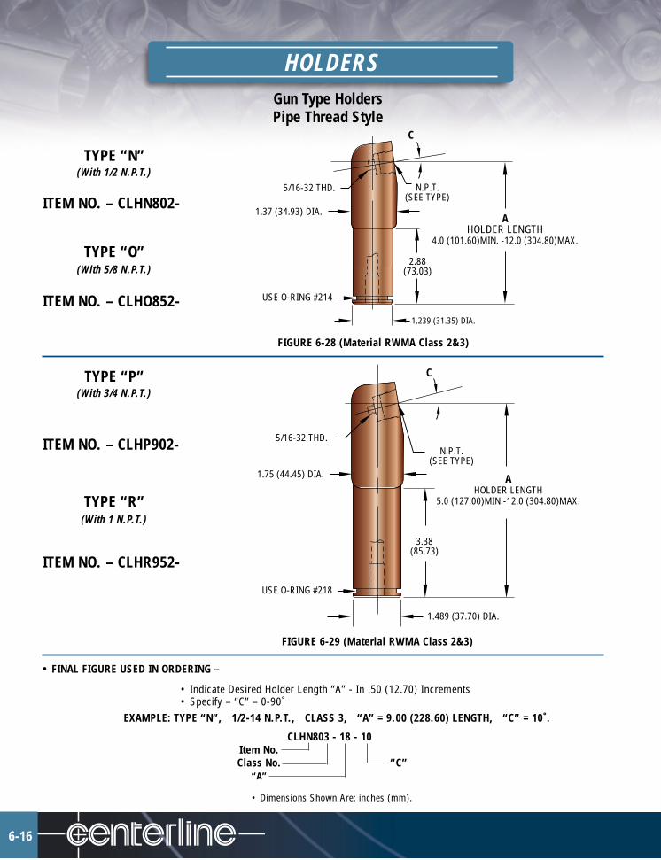
6-16
HOLDERSGun Type HoldersPipe Thread Style
TYPE “N”(With 1/2 N.P.T.)
ITEM NO. – CLHN802-
TYPE “O”(With 5/8 N.P.T.)
ITEM NO. – CLHO852-
FIGURE 6-28 (Material RWMA Class 2&3)
TYPE “P”(With 3/4 N.P.T.)
ITEM NO. – CLHP902-
TYPE “R”(With 1 N.P.T.)
ITEM NO. – CLHR952-
FIGURE 6-29 (Material RWMA Class 2&3)
• FINAL FIGURE USED IN ORDERING –
• Indicate Desired Holder Length “A” - In .50 (12.70) Increments• Specify – “C” – 0-90˚
EXAMPLE: TYPE “N”, 1/2-14 N.P.T., CLASS 3, “A” = 9.00 (228.60) LENGTH, “C” = 10˚.
CLHN803 - 18 - 10Item No.Class No. “C”
“A”
• Dimensions Shown Are: inches (mm).
3.38(85.73)
N.P.T.(SEE TYPE)
1.75 (44.45) DIA.
C
1.489 (37.70) DIA.
USE O-RING #218
5/16-32 THD.
AHOLDER LENGTH
5.0 (127.00)MIN.-12.0 (304.80)MAX.
2.88(73.03)
N.P.T.(SEE TYPE)
1.37 (34.93) DIA.
C
1.239 (31.35) DIA.
USE O-RING #214
5/16-32 THD.
AHOLDER LENGTH
4.0 (101.60)MIN. -12.0 (304.80)MAX.

SPOT WELDING MACHINE ARMS & CAPS
CenterLine Spot Welding Machine Arms are engineered and manufactured to accommodate any of the standard lineCenterLine Electrode Holders as well as most other special shank type holders which might be required for specific specialapplications.
Among the benefits to be obtained from use of our Spot Welding Arms are:• reduction in required set-up time resulting from easier front attachment feature.• extended arm life which occurs as a consequence of reduced bolt hole thread wear. Hole and threads are cut through steel insert
which is less malleable than copper used for basic arm.
NOTE: CenterLine can engineer and/or manufacture special spot welding machine arms for particular applications based oncustomer specifications.
EXAMPLE: Arm & Cap Assembly, “A” Dia. = 3.00 (76.20), “B” Dia. = 1.25 (31.75), “C” = 36.00 (914.40).
CLRAC - 1210 - 36Item No.
“A”“B” “C”
• Dimensions Shown Are: inches (mm).
ORDERING CHARTCLRA STANDARD PREFIX - ARM (ONLY)CLRC STANDARD PREFIX - CAP (ONLY)CLRAC STANDARD PREFIX - ARM & CAP ASSEMBLY04 THRU 16 “A” DIAMETER - .25 (6.35) INCREMENTS06 THRU 16 “B” DIAMETER - .12 (3.18) INCREMENTS8 THRU 50 “C” DIMENSION - 1.00 (25.40) INCREMENTS“B” OR “S” BRASS OR STEEL - (CAP ONLY)
.50 (12.70)
A
B(SHANK DIA.)
C
CAP STEEL ROD INSERT ARMMATERIAL - STEEL OR BRASS MATERIAL - HARD DRAWN COPPER
7-1
FIGURE 7-1
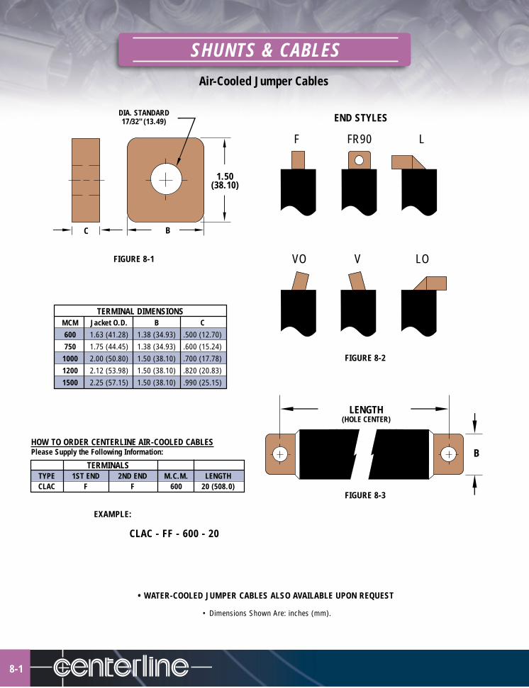
8-1
SHUNTS & CABLESAir-Cooled Jumper Cables
TERMINAL DIMENSIONSMCM Jacket O.D. B C600 1.63 (41.28) 1.38 (34.93) .500 (12.70)750 1.75 (44.45) 1.38 (34.93) .600 (15.24)1000 2.00 (50.80) 1.50 (38.10) .700 (17.78)1200 2.12 (53.98) 1.50 (38.10) .820 (20.83)1500 2.25 (57.15) 1.50 (38.10) .990 (25.15)
HOW TO ORDER CENTERLINE AIR-COOLED CABLESPlease Supply the Following Information:
TERMINALSTYPE 1ST END 2ND END M.C.M. LENGTHCLAC F F 600 20 (508.0)
DIA. STANDARD17/32" (13.49)
C B
1.50(38.10)
LENGTH(HOLE CENTER)
B
EXAMPLE:
CLAC - FF - 600 - 20
• WATER-COOLED JUMPER CABLES ALSO AVAILABLE UPON REQUEST
• Dimensions Shown Are: inches (mm).
END STYLES
FIGURE 8-2
VO V LO
F FR90 L
FIGURE 8-1
FIGURE 8-3
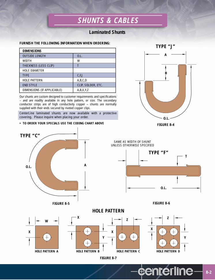
SHUNTS & CABLESLaminated Shunts
8-2
Our shunts are custom designed to customer requirements and specifications– and are readily available in any hole pattern, or size. The secondaryconductor strips are of high conductivity copper – shunts are normallysupplied with their ends secured by riveted copper clips.
CenterLine laminated shunts are now available with a protectivecovering. Please inquire when placing your order.
• TO ORDER YOUR SPECIALS USE THE CODING CHART ABOVE
A
B
O.L.
O.L. A
O.L.
T
SAME AS WIDTH OF SHUNTUNLESS OTHERWISE SPECIFIED
W
X
X
Y
X
Z
X
Z
Y
TYPE “J”
TYPE “F”
HOLE PATTERN
FIGURE 8-4
FIGURE 8-6
FIGURE 8-7
HOLE PATTERN A HOLE PATTERN B HOLE PATTERN C HOLE PATTERN D
FIGURE 8-5
TYPE “C”
FURNISH THE FOLLOWING INFORMATION WHEN ORDERING:
DIMENSIONSOUTSIDE LENGTH O.L.WIDTH WTHICKNESS (LESS CLIP) THOLE DIAMETERTYPE C,F,JHOLE PATTERN A,B,C,DEND STYLE CLIP, SOLDER, ETC.DIMENSIONS (IF APPLICABLE) A,B,X,Y,Z

9-1
WATER TUBES
ITEM NO. – CLT-1000-
TYPE “A”
(Use with Telescoping TubesType “B” & “C”)
FIGURE 9-1 (Material - 1/4 ID BRASS TUBE)
ITEM NO. – CLT-1200-
TYPE “B”
(Use with 4 RW Electrodes)
FIGURE 9-2 (Material - Copper)
ITEM NO. – CLT-1300-
TYPE “C”
(Use with 5, 6 & 7 RW Electrodes)
FIGURE 9-3 (Material - Copper)
ITEM NO. – CLT-1400-
TYPE “D”
(Use with 5, 6 & 7 RW Electrodes)
FIGURE 9-4 (Material - Copper & Brass)
ITEM NO. – CLT-1500-
TYPE “E”
(Use with 4 RW Electrodes)
FIGURE 9-5 (Material - Copper & Brass)
ATUBE LENGTH.75 (19.20) MIN.
.20 (5.16)
.312 (7.94) DIA.
.04 (1.02)ROLLED RECESS
5/16-32 THD.
.30 (7.54)
.20 (5.16)
ATUBE LENGTH
1.25 (31.75) MIN.
.245 (6.23) DIA.
.50 (12.70)
.218 (5.59) DIA.
45˚
ATUBE LENGTH
1.25 (31.75) MIN.
.245 (6.23) DIA.
45˚TYP.
ATUBE LENGTH
1.25 (31.75) MIN.
.25 (6.35)
.245 (6.23) DIA.
5/16-32 THD.
45˚
ATUBE LENGTH
1.25 (31.75) MIN..25 (6.35)
5/16-32 THD.
.187 (4.83) DIA.
45˚

WATER TUBES
• Dimensions Shown Are: inches (mm).
ITEM NO. – CLT-1600-
TYPE “F”B = .210 (5.31) DIA.
ITEM NO. – CLT-1700-
TYPE “G”B = .250 (6.35) DIA.
FIGURE 9-6 (Material - Interlocked Flexible Brass)
ITEM NO. – CLT-1800-
TYPE “H”
FIGURE 9-7 (Material - Interlocked Flexible Brass)
ITEM NO. – CLT-1900-
TYPE “I”
(Use with 5, 6 & 7 RW Electrodes)
FIGURE 9-8 (Material - Copper & Brass)
ITEM NO. – CLT-2000-
TYPE “J”
(Use with 5, 6 & 7 RW Electrodes)FIGURE 9-9 (Material - Copper & Brass)
PART NUMBER CODING• Indicate Desired Tube Length “A” -
In .12 (3.18) IncrementsEXAMPLE: TYPE “G” WITH 1.50 (38.10) LENGTH
CLT - 1700 -12“A”
Item No. Length
9-2
ATUBE LENGTH
1.25 (31.75) MIN.
.25 (6.35)
B DIA.
5/16-32 THD. FLEXIBLE BRASSTUBING
ATUBE LENGTH
1.25 (31.75) MIN.
.25 (6.35)
.50 (12.70)
.245(6.23) DIA.
3/8-32 THD.FLEXIBLE BRASSTUBING
ATUBE LENGTH
1.25 (31.75) MIN..38 (9.53)
.245(6.22) DIA.
5/16-32 THD.
.25 (6.35)
ATUBE LENGTH
1.25 (31.75) MIN..38 (9.53)
.187(4.75) DIA.
5/16-32 THD.
.25 (6.35)
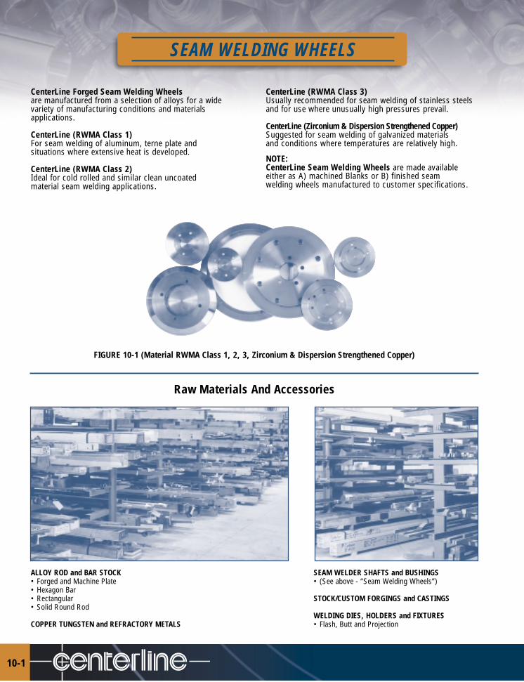
10-1
SEAM WELDING WHEELS
CenterLine Forged Seam Welding Wheelsare manufactured from a selection of alloys for a widevariety of manufacturing conditions and materialsapplications.
CenterLine (RWMA Class 1)For seam welding of aluminum, terne plate andsituations where extensive heat is developed.
CenterLine (RWMA Class 2)Ideal for cold rolled and similar clean uncoatedmaterial seam welding applications.
CenterLine (RWMA Class 3)Usually recommended for seam welding of stainless steelsand for use where unusually high pressures prevail.
CenterLine (Zirconium & Dispersion Strengthened Copper)Suggested for seam welding of galvanized materialsand conditions where temperatures are relatively high.
NOTE:CenterLine Seam Welding Wheels are made availableeither as A) machined Blanks or B) finished seamwelding wheels manufactured to customer specifications.
FIGURE 10-1 (Material RWMA Class 1, 2, 3, Zirconium & Dispersion Strengthened Copper)
Raw Materials And Accessories
ALLOY ROD and BAR STOCK SEAM WELDER SHAFTS and BUSHINGS• Forged and Machine Plate • (See above - “Seam Welding Wheels”)• Hexagon Bar• Rectangular STOCK/CUSTOM FORGINGS and CASTINGS• Solid Round Rod
WELDING DIES, HOLDERS and FIXTURESCOPPER TUNGSTEN and REFRACTORY METALS • Flash, Butt and Projection

GREASE EQUALIZERS
CenterLine grease equalizers are available in a variety of styles and configurations to satisfy nearly all multi-spot weldingapplications. Unlike spring style units, the CenterLine grease equalizers ensure that equal pressure is distributed to all spot locations.
CenterLine can also design and manufacture custom weld fixtures.
Advantages include:• High quality, rugged design for trouble-free operation• Simple construction for ease of maintenance• Up to four units may be used with one mounting plate
Contact CenterLine for specific information concerning styles and availability.
11-1
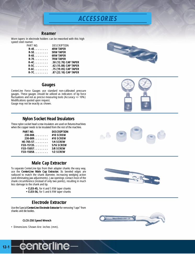
12-1
ACCESSORIES
ReamerWorn tapers in electrode holders can be reworked with this highspeed steel reamer.
PART NO. DESCRIPTIONR-4E . . . . . . . . 4RW TAPERR-5E . . . . . . . . 5RW TAPERR-6E . . . . . . . . 6RW TAPERR-7E . . . . . . . . 7RW TAPERR-4C . . . . . . . . .50 (12.70) CAP TAPERR-5C . . . . . . . . .62 (15.88) CAP TAPERR-6C . . . . . . . . .75 (19.05) CAP TAPERR-7C . . . . . . . . .87 (22.10) CAP TAPER
GaugesCenterLine Force Gauges use standard non-calibrated pressuregauges. These gauges should be utilized as indicators of tip forcefluctuations and not as precise measuring tools (Accuracy +/- 10%)Modifications quoted upon request.Gauge may not be exactly as shown.
Nylon Socket Head InsulatorsThese nylon socket head screw insulators are used on fixtures/machineswhen the copper needs to be insulated from the rest of the machine.
PART NO. DESCRIPTION230-008 . . . . . . . . #10 SCREW230-009 . . . . . . . . #10 SCREW
HE-705-57 . . . . . . . . 1/4 SCREWFSD-15135 . . . . . . . . 5/16 SCREWFSD-15057 . . . . . . . . 3/8 SCREWFSD-15058 . . . . . . . . 1/2 SCREW
Male Cap ExtractorTo separate CenterLine tips from their adapter shanks the easy way,use the CenterLine Male Cap Extractor. Its beveled edges areradiused to match the shank diameter, increasing wedging action(and eliminating jaw adjustments). Jaw openings contact most of theshank circumference (instead of only two points), resulting in muchless damage to the shank and tip.
• CLEX-45, for 4 and 5 RW taper shanks• CLEX-56, for 5 and 6 RW taper shanks
Electrode ExtractorUse the Special CenterLine Electrode Extractor for removing “caps” fromshanks and die bodies.
CLCX-250 Speed Wrench
• Dimensions Shown Are: inches (mm).

MALE CAP DATA
REFERENCE DATA
.285(7.237)
.375(9.525)
.390(9.910)
.415(10.537)
.500(12.700)
.501(12.725)
.500(12.700)
.613(15.566)
.374(9.502) .414
(10.512).500
(12.700).612
(15.541)
.394(10.012)
.495(12.577)
.625(15.875)
.625(15.875)
.348(8.843)
.348(8.843)
.402(10.211)
.380(9.650)
.502(12.751) .633
(16.076)
.475(12.067)
.633(16.076)
.475(12.067)
1° 26' 1° 26' 1° 26' 1° 26'
1° 26' 1° 26' 1° 26' 1° 26'
2° 56 ' 53" 2° 56 ' 53" 2° 56 ' 53" 2° 56 ' 53"
1.25TAPER/ft
1.25TAPER/ft
1.25TAPER/ft
1.25TAPER/ft
.482 .63 .75 .88(12.24) (15.87) (19.05) (22.23)
FEMALE CAP DATA
.482 .63 .75 .88(12.24) (15.87) (19.05) (22.23)
• Dimensions Shown Are: inches (mm).
13-1

13-2
REFERENCE DATA
(Refer to pages 4-12 to 4-14)ELECTRODE AND ADAPTER TAPERS CAP TAPERS
#0 MT - #3 RW
#1 MT - #4 RW
#2 MT - #5 RW
#6 RW
#3 MT - #7 RW
• Dimensions Shown Are: inches (mm).
.375(9.53)
.375(9.53)
.350(8.89)
.364(9.24)
.500(12.70)
.500(12.70)
.484(12.29)
.438(11.12)
.463(11.76)
.875(22.23)
.500(12.70)
.625(15.88)
.588(14.63)
.613(15.57)
.750(19.05)
.500(12.70)
.750(19.05)
.706(17.93)
.731(18.57)
.875(22.23)
.875(22.23)
.500(12.70)
.819(20.80)
.844(21.44)
1.125(31.75)
.285(7.237)
.484(12.29)
.375(9.53)
.375(9.53)
.375(9.53)
.625(15.88)
.415(10.54)
.500(12.70)
.500(12.70)
.750(19.05)
.500(12.70)
.625(15.88)
.500(12.70)
.875(22.23)
.625(15.88)
.613(15.56)
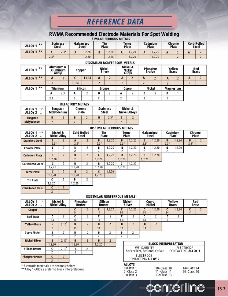
RWMA Recommended Electrode Materials For Spot Welding
REFERENCE DATA
ALLOY 1 ** Stainless Galvanized Tin Terne Cadmium Chrome Cold-RolledSteel Steel Plate Plate Plate Plate Steel
ALLOY 1 ** A 2,3* A 1,2,20 B 1,2,20 A 1,2,20 A 1,2,20 A 2 A 2
2,3* 1,2,20 1,2,20 1,2,20 1,2,20 2 2
Aluminum & Nickel &ALLOY 1 ** Aluminum Nickel- Nickel Phosphor Yellow Red
AlloysCopper Silver Alloys Bronze Brass Brass
ALLOY 1 ** A 1 C 13,14 A 2 A 2 A 2 A 2 A 21 13,14 2 2 2 2 2
ALLOY 1 ** Titanium Silicon Bronze Cupro Nickel MagnesiumA 2,3 A 2 B 2 A 2 B 2 B 1
2,3 2 2 2 2 1
ALLOY 1 Tungsten Chrome Stainless Nickel &ALLOY 2 Molybdenum Plate Steel Nickel Alloys
Tungsten B 2 B 2 B 2,3* B 2Molybdenum 2 2 2 2
ALLOY 1 Nickel & Cold-Rolled Tin Terne Galvanized Cadmium ChromeALLOY 2 Nickel Alloy Steel Plate Plate Steel Plate Plate
Stainless Steel B 2 A 2 B 1,2,20 B 1,2,20 B 1,2,20 B 1,2,20 B 22,3* 2,3* 2,3* 2,3* 2,3* 2,3* 2,3*
Chrome Plate B 2 B 2 B 1,2,20 B 1,2,20 B 1,2,20 B 1,2,202 2 2 2 2 2
Cadmium Plate B 2 B 2 C 1,2,20 B 1,2,20 B 1,2,201,2,20 2 1,2,20 1,2,20 1,2,20
Galvanized Steel C 2 B 2 B 1,2,20 C 1,2,201,2,20 1,2,20 1,2,20 1,2,20
Terne Plate C 2 B 2 C 1,2,201,2,20 1,2,20 1,2,20
Tin Plate C 2 B 21,2,20 1,2,20
Cold-Rolled Plate C 22
ALLOY 1 Nickel & Phosphor Silicon Nickel- Cupro Yellow RedALLOY 2 Nickel Alloy Bronze Bronze Silver Nickel Brass Brass
Copper C 2 C 1,2,20 C 1,2,20 C 1,2,20 C 1,2,20 C 214 14 14 14 14 14
Red Brass C 2 C 2 C 2 C 2 C 2 C 214 14 14 1 4 14 2
Yellow Brass C 2,10* B 2 B 2 B 2 B 22 11 11 11 11
Cupro Nickel B 2 B 2 B 2 B 22 2 2 2
Nickel-Silver B 2,10* B 2 B 21,2,20 1,2,20 1,2,20
Silicon Bronze C 2,10* B 22 2
Phosphor Bronze C 22
* Electrode materials are second choices**Alloy 1=Alloy 2 (refer to block interpretation)
BLOCK INTERPRETATION
DISSIMILAR NONFERROUS METALS
DISSIMILAR FERROUS METALS
DISSIMILAR NONFERROUS METALS
SIMILAR FERROUS METALS
REFACTORY METALS
WELDABILITY ELECTRODEA=Excellent, B=Good, C=Fair CONTACTING ALLOY 1
ELECTRODECONTACTING ALLOY 2
ALLOYS1=Class 1
11=Class 112=Class 213=Class 133=Class 3
14=Class 1410=Class 1020=Class 20
13-3
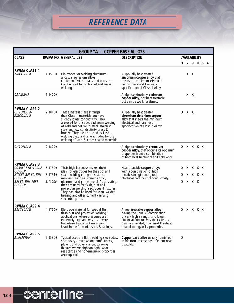
13-4
REFERENCE DATA
GROUP “A” – COPPER BASE ALLOYS –CLASS RWMA NO. GENERAL USE DESCRIPTION AVAILABILITY
1 2 3 4 5 6
RWMA CLASS 1ZIRCONIUM 1.15000 Electrodes for welding aluminum A specially heat treated X X
alloys, magnesium alloys, zirconium copper alloy thatcoated materials, brass and bronzes. meets the minimum electricalCan be used for both spot and seam conductivity and hardnesswelding. specification of Class 1 Alloy.
CADMIUM 1.16200 A high conductivity cadmium X Xcopper alloy, not heat treatable,but can be work hardened.
RWMA CLASS 2CHROMIUM- 2.18150 These materials are stronger A specially heat treated X X XZIRCONIUM than Class 1 materials but have chromium zirconium copper
slightly lower conductivity. They alloy that meets the minimumare used for the spot and seam welding electrical and hardnessof cold and hot rolled steel, stainless specification of Class 2 Alloys.steel and low conductivity brass &bronze. They are also used as flashwelding dies, and as electrodes for thewelding of steel & other coated materials.
CHROMIUM 2.18200 A high conductivity chromium X X X X Xcopper alloy, that obtains its optimumproperties from a combinationof both heat treatment and cold work.
RWMA CLASS 3COBALT-BERYLLIUM 3.17500 Their high hardness makes them Heat treatable copper alloys X X X X XCOPPER ideal for electrodes for the spot and with a combination of highNICKEL-BERYLLIUM 3.17510 seam welding of high resistance tensile strength and good X X X X XCOPPER materials such as stainless steel, electrical and thermal conductivity.BERYLLIUM-FREE 3.18000 nichrome and monel metal. As a casting, X X X XCOPPER they are used for flash, butt and
projection welding electrodes & fixtures.They can also be used for seam welderbearing and other current carryingstructural parts.
RWMA CLASS 4BERYLLIUM 4.17200 Electrode material for special flash, A heat treatable copper alloy X X X X X
flash butt and projection welding having the unusual combinationapplications where pressures are of very high strength and lowerextremely high and wear is severe electrical conductivity than Class 3.but where heat is not excessive. Can be annealed, machined & reheatUsed in the form of inserts & facings. treated to regain its properties.
RWMA CLASS 5ALUMINUM 5.95300 Typical uses are flash welding electrodes, Copper base alloy usually furnished X
secondary circuit welder arms, knees, in the form of castings. It is not heatplatens and other current carrying treatable.fixtures where high strength, wearresistance and non-magnetic propertiesare required.

REFERENCE DATA
GROUP “B” – REFRACTORY METAL COMPOSITION –CLASS RWMA NO. GENERAL USE DESCRIPTION AVAILABILITY
1 2 3 4 5 6RWMA CLASS 10COPPER-TUNGSTEN 10.74450 Flash and butt welding electrodes A powder metallurgical combination X X
where higher electrical and thermal of 45% copper & 55% of the refractoryconductivity is necessary and where metal tungsten. Not a true alloy. This a degree of malleability is desired. combination produces dense, hard metalsThey can also be used for spot welding of superior wear resistance and strength atlow conductivity steels -- stainless. elevated temperatures.
RWMA CLASS 11COPPER-TUNGSTEN 11.74400 Projection welding electrodes, flash A powder metallurgical combination X X
& butt welding electrodes, light upsetting of 25% copper and 75% of the refractoryelectroforging & seam welder bushings. metal tungsten. Not a true alloy. ThisHarder than Class 10 & used where combination produces dense, hard metalsmoderate pressure required. with good thermal & electrical conductivity.
RWMA CLASS 12COPPER-TUNGSTEN 12.74350 Heavy duty projection welding electrodes, A powder metallurgical combination X X
electro-forming & electroforging electrodes, of 20% copper and 80% of the refractoryelectrode facing for upsetting of studs metal tungsten. Not a true alloy. Thisand rivets, cross wire welding of large combination produces dense, hard metalsdiameter wire and rod. of superior wear resistance and strength at
elevated temperatures.
RWMA CLASS 13TUNGSTEN 13.74300 Cross wire welding of copper & brass Tungsten is extremely hard and has low X X X
electrobrazing and some electro ductility. It cannot be machined but can beupsetting. Welding of braided copper ground to required contours. It does not alloywire to other materials. with non-ferrous materials.
RWMA CLASS 14MOLYBDENUM 14.42300 Cross wire welding of copper & brass Molybdenum is not as hard as Class 13 and X X X X
electrobrazing and some electro upsetting. can be drilled and machined to specialWelding of braided copper wire to contours.other materials.
GROUP “C” – SPECIALTY MATERIAL –RWMA CLASS 20DISPERSION 20.15760 Welding of metallic coated metal A powder metallurgy material consisting X XSTRENGTHENED such as galvanized steel, tern of copper and aluminum oxide with highCOPPER plate, etc. temperature hardness and physical properties
different than the copper alloys.
AVAILABILITY CODING EXPLANATION• 1 = CASTING• 2 = FORGING• 3 = ROD & BAR• 4 = PLATE• 5 = TUBE• 6 = INSERTS
• GENERAL SUGGESTED APPLICATIONS, NOT TO BE INTERPRETED AS THE OPTIMUM FOR ANY SPECIFIC APPLICATION
13-5

13-6
REFERENCE DATA
OVEREXPOSURE EFFECTS
RWMA RWMA RWMA ZIRCONIUMTYPE/LOCATION OF OVEREXPOSURE CLASS 1 CLASS 2 CLASS 3 COPPER TUNGSTEN GLIDCOP
Skin: Irritation with possible discoloration of skin or hair. X X X X N/A
Skin: Irritation with possible discoloration of skin (Copper).On broken skin, can cause granulomatous lesions (hard lesionswith a central non-healing core) (Beryllium). Cobalt can cause Xan allergic sensitivity even with very low exposures. Oftenexpressed as eruptions in creases of elbow, knee, ankles and neck.
Inhalation: Upper respiratory tract irritation, metallic taste inmouth, nausea, metal fume fever (sensation of chills and stuffiness X X X X N/Aof the head and weakness). Possible lesions on nasal passages.
Inhalation: Upper respiratory tract irritation, metallic taste inmouth, nausea, metal fume fever. Possible lesions on nasalpassages (Copper). Cough, substernal pain, moderate shortness ofbreath, some weight loss (Beryllium). Chronic Beryllium disease Xcan exhibit these symptoms plus weakness and fatigue. Severitycan be from non-disabling to severely disabling. High Cobaltinhalation levels can cause asthma-like symptoms to interstitialpneumonia with fibrosis in severe cases.
Eyes: Metal particles penetrating the eyes may cause irritation X X X X Xdiscoloration and damage.
Eyes: Copper particles penetrating the eye may cause irritationdiscoloration and damage. Beryllium dust and fumes may cause Xirritation and conjunctivitis.
Cadmium – reported to increase incidence of prostate cancer. X
Beryllium & Nickel – classed as suspect of carcinogenic Xpotential for man.
Chromium – dust and fumes can cause skin and pulmonary Xsensitization and is corrosive. Overexposure is unlikely to occur.
REACTIVITYHazardous Polymerization: Will not occur.Stability: StableIncompatibility: Dust or fume contact / acetylene gas may cause X X X X Xformation of copper acetylenes which are sensitive to shock.
Hazardous Decomposition Products: XMelting may generate harmful fumes.
EMERGENCY &FIRST AID PROCEDURES
Skin: Wash contaminated skin using soap or mild detergent and water. If irritationpersists after washing, get medical attention. Eyes: Wash eyes immediately withlarge amounts of water, lifting lower and upper lids occasionally.
Get medical attention immediately.

REFERENCE DATA
CONTRACT TERMS & CONDITIONS APPLICABLE TO ALL SALES
LIMITED WARRANTYCenterLine (Windsor) Limited, Electrodes Division, hereby provides to purchaser a limited warranty that its products and parts aremanufactured free from defects in material and workmanship subject to the following DISCLAIMERS of WARRANTIES, limitations ofliability, and EXCLUSIVE REMEDY provisions set forth below. Said warranty shall only be available to the original purchaser of theproducts or parts.
DISCLAIMERS OF WARRANTIES AND LIMITATIONS OR LIABILITY AND EXCLUSIVE REMEDY
A. The limited warranty set forth above is in lieu of any and all other expressed warranties.
B. Manufacturer disclaims any and all implied warranties and disclaims any and all warranties of merchantability and warranties offitness for a particular purpose.
C. The liability of manufacturer for a breach or violation of any warranty is limited to repair or replacement (at manufacturer’s option)of the defective product or parts.
D. All other liability of manufacturer with respect to, arising from, or in connection with the purchase of the products or parts or inconnection with this agreement or from manufacture, installation, maintenance, repair or use of any products or parts, whetherin contract or in tort or otherwise is limited to the amounts paid (purchase price) by the purchaser to manufacturer for such partsor products.
E. Manufacturer shall not be liable or responsible for direct damages or for indirect damages or for incidental damages or forconsequential damages or for the loss of the use of any asset or for the loss or revenue or for the loss of profit, anything in thisagreement or in any other document to the contrary notwithstanding. The remedies set forth in this document, are the sole andexclusive remedies available against manufacturer. All damages (including attorney fees and litigation costs) exceeding thepurchase price of the products or parts are hereby expressly excluded and expressly disclaimed by the manufacturer.
F. Written notice of any defects in parts or products must be provided to manufacturer within one (1) year of the date of purchaseby registered mail or certified mail, return receipt requested and any product or part believed to be defective must be returned tomanufacturer’s plant at purchaser’s cost within said one (1) year. Any legal action based on any claim against manufacturer forbreach of warranty must be commenced within one (1) year after date of purchase: otherwise, said claim shall be barred, void andunenforceable.
G. Manufacturer shall not be liable or responsible for any damages arising from injury in shipment, faulty installation, adjustmentsor repairs, exposure to excessive pressure, temperature or harmful chemicals or improper application or misuse or abuse of saidproducts or parts and/or negligence of others.
DISCLAIMER OF LIABILITY
The information in these Material Safety Data Sheets in this section was obtained from sources which we believe are reliable. However,the information is provided without any warranty, express or implied, regarding its correctness. The conditions or methods ofhandling, storage, use and disposal of the product are beyond our control and may be beyond our knowledge. For this and otherreasons, we do not assume responsibility and expressly disclaim liability for loss, damage, or expense arising out of or in any wayconnected with the handling, storage, use, or disposal of the product.
13-7

OTHER PRODUCTS
14-1
CenterLine manufactures a variety of products to satisfy resistance welding and metal working needs.Contact CenterLine for additional information on other products.
RESISTANCE WELDING EXPERTISECenterLine has a broad range of proven resistance welding gun solutions.
The CenterLine product range includes:
• basic solutions to satisfy your general needs
• custom solutions to address your unique requirements
• innovative solutions to meet your future needs.
Our knowledge and experience are reflected in a family of resistancewelding gun solutions that are well suited for tough industrialenvironments. A culture of continuous improvement has helped usimprove our product line by simplifying installation, improvingdurability, and requiring minimal maintenance.
We have diverse engineering and manufacturing capabilities to turnyour unique requirements or ideas into a solution that will give you acompetitive advantage.
Standard CenterLineTM solutions all offer low-impact operation. OurStaacTM air cylinder, OHMA® air/oil cylinder, or servo-electric actuator,will help ensure you can:
maximize up-time by decreasing wear
reduce operating cost by maximizing consumable life
minimize noise
decrease shock and vibration
minimize electrode skidding
control dimensional variation
improve weld appearance
Contact CenterLine’s Components Division forinformation on these other products.
Tel. (519)734-8330 or (800) 268-8330

OTHER PRODUCTS
14-2
OHMA® Welding CylindersThe OHMA intensifier cylinder produces consistent welding forces with lowimpact. It is ideal for high force applications and space restrictive locations.This cylinder operates with a low impact advance stroke resulting in prolongedelectrode life, reduced part deformation and decreased overall shock to theequipment.
AMSI Welding CylindersAmerican Machining Specialties Incorporated (AMSI) coupled with CenterLine,offers a comprehensive line of new air cylinders:• Dual Piston Cylinders • Triple Piston Cylinders • Pre-Lube Cylinders • Retract Cylinders • Proximity Switch Cylinders • Hydraulic Cylinders The line of standard cylinders provide direct replacements for a large variety ofweld cylinder applications. In addition to the standard line we also offer inhouse design to fit our customer's specific requirements as well asreplacement seal kits and parts for competitive brands.
OHMA® Piercing CylindersThe OHMA piercing cylinder offers a robust design and remains one of themost practical and trouble-free systems available today. By using shop airpressure and hydraulic fluid, the OHMA cylinder produces work forces rangingfrom one ton to hundreds of tons. Rod, stroke and mounting style optionsmake the OHMA cylinder suitable for virtually all metalworking applications.
OHMA® Press PackagesThe OHMA press family is a collection of presses ranging from 4 to 70 tons.The presses are designed to satisfy production needs, prototype work orserves as an all purpose press. The design offers total flexibility with a softtouch, non-shock approach to the part and a 1/2" high force work stroke. Thesepresses are ideal for piercing, pierce nut installation, crimping, coining,marking, forming, stamping, etc.

Canada:
595 Morton Dr., Windsor, Ontario N9J 3T8
U.S.A.:
P.O. Box 321187, Detroit, MI 48232-1187
Canada (519) 734-6886
U.S. (313) 961-4080
Fax: (519) 734-2005
Email: [email protected]
Toll Free in Canada & U.S. 1-800-249-6886
www.cntrline.com
Printed in Canada Copyright © 2003, CenterLine (Windsor) Limited EL-PG-P-7.0-0303