july 13, 1-948
TRANSCRIPT

July 13, 1-948.
Filed oct. a, 1946
COPPE
l JA
PRODUCTION 'oF sxß GLAss SURFACE WITH F
l
H. NICOLL , LETONIZED LOW REFLECTANGE
LUOS $111 CIC AC ID VAPOR
2,445,238 ETAL
6 Sheets-Sheet 1
111
Il
\ \\\\\\
JLU
3 ent
Imran/f HMM?? "s â Fad E. Imlfmf
l8r v A .
Gttomeg

July 13, 1948.
Filed oct. a, 194e
F. H. NICOLL ET AL PRODUCTION 0F sKELE'roNIzED Low REFLECTANGE GLASS SURFACE vwrm FLUosILICIc ACID VAPOR
¿445,238
6 Sheets-Sheet 2
L51.
JW. /cA /w/Mafl? KJ)
à N
966.55454
f
f
z5 ¿a .2.5 Assay /M/f. )
(aux 7W! .4 Paire)V
HLM.: .snow aarrfo uns. »Mawr 20% a/v 77M! Ava/Rss. p4 r4 f90/w 2% /f/¿w 6am;
k , ‘uv o 7
f1’ .4b ï § -f è S 5 ë "I 1.5 2.o 2.5
Asswyrag/l.) (aus: rypfa mmol)
@19M Gttorneg
Bu
July 13, 1948- F. H. NlcoLl. ET Al. 2,445,238 PRODUCTION OF SKELETONÍZED LOW REFLECTANCE GLASS SURFACE WITH FLUOSILICIC ACID VAPOR
Filed Oct. 8, 1946 6 Sheets-Sheet 3
ÚPAQl/f' OBJECT
// /
4'5676-91a/f/2
CMM@ Gîtorneg
Bl

July 13, 1948- F. H. NlcoLl. ETAL 2,445,238 PRODUCTION OF SKELETONIZED LOW REFLECTANCE GLASS SURFACE WITH FLUOSILICIG ACID VAPOR .
Filed Oct. 8, 1946 ' 6 Sheets-Sheet 4
4 man
300
20o '
ma .fa sa 2a fo ~ .5 3 z f
w/vœWr/Mr/a/v of' @2x41 75)
Í/_Íl l0 ffy/PHP4 70H5 (056MB @mmf/M05) 55 .50 50 z5 20 f5 l0 5 0 4.5 40 35
3000
zooo ' ifffcr of rfMPf'iAraRf 0,1/ 77M'
77,145 aF rifnrMfA/r of ïyPE 5
3.5 6M. snow w75 @A4553 foon >
900 aaa 700
600
.500
400
300
3.7 32 J3 ,I4 J5 .16° 3.7
j Gttorneg Bl
July 13; 1948« - " F. H. NlcoLL ETAL 2,445,238 PRODUCTION 0F SKEI‘JETONIZED LO' REFLECTÀNGE GLASS SURFACE '1TH FLUOSILIGIC ACID VAPOR
Filed Oct, 8, 1946 ' 6 Sheets-Sheet 5
„20304050 l0 ¿0 J0 40 .50 0 /Mßß/vfff MMD/mr:
l/ f1; f4 :AMPLI a 15% #zag .MMPzfo x57; aan@
M0 /00
sa ì i0
l fro/vars
E
[MRD/YEL? 4
4 4
3 ' 0 , 2 . 4 ‘
#6M Ji@ ,40050 Pfl Ml. ~Milf/dll ' ’ _ . Sgnentors
Frederzcl: E Nico/Í t ¿e Fard L Wïlzidmf
. n úttorneg

July 13, 1948. . F. H. NlcoLl. ETAL ` 2,445,238 y PRODUGTION 0F SKÈLETONIZED LOW REFLECTANCE GLASS' SURFACE '1TH FLUOSILICIC ACID VAPOR v
Filed Oct; 8, 1946 6 Sheets-Sheet 6
IN
Bmxntors [bede-rick Il M’call d Fard E. ìñ’llümd‘
a. Gttomeg
A Patented July 13, 1948 2,445,238
2,445,238
_UNITED STATES PATENT oFFlcE PRODUCTION> 0F SKELETONIZED LOW RE FLECTANCE GLASS SURFACE WITH FLUO SILICIC ACID VAPOR ‘
Frederick H. Nicoll and Ferd E. Williams, Prince ton, N. J., asslgnors to Radio Corporation of America, a corporation of Delaware
Application October 8, 1946, Serial No. 701,902
(Cl. 41-42) ' ~ 7 Claims.
1 This application is a continuation-impart of an
application of Nicoll and Williams, Serial No. 488,938, filed May 28, 1943, for “Low reflective elements,” now abandoned. The invention relates to elements made of glass or the like and pro vided with a low reflective illm or coating on the part of its surface normally presented 'to an ob server. Such a low refiective element is disclosed
' and claimed in a _copending application of VFed erick H. Nicoil, Ser. No. 461,958, filed October 14, 1942, and assigned to the same assignee as the present application. In accordance with this copending application, the glass surface is treated with dilute hydrofluoric acid vapor under condi tions promoting substantially uniform gas con centration and ̀ distribution at the treated sur
_ face, the treated surface being maintained at a temperature higher than that of the acid solu ~tion in order to prevent condensation~ of moisture at the treated surface, and thev treatment being continued until a layer skeletonized to the de sired extent and having the desired thickness' is formed. . While the m thod of treatment disclosed by
the aforesaid application has proved satisfactory in many respects, the necessity of maintaining a temperature difference between the treated sur face and hydrofluori'c acid‘ bath or solution is a
Il commercial fluosiliclc acids
2 treat the surface of a transparent body such as glass with vapor derived from a solution of fluo sllici‘c acid while maintaining the silica number of the acid ait a value conducive to the production Aof a hard skeletonized fllm of low reflectance. The invention will be better understood from
.the following description when considered in con nection with the accompanying drawings, .in which ` '
Figs.A l to 3 are cross-sectional views of three embodiments of an apparatus useful in practicing this invention;
Figs. 4a to 4d show time of treatment as a func tion of the assay and silica number of the acid;
Fig. 5 shows the assay and silica number of with relation to the
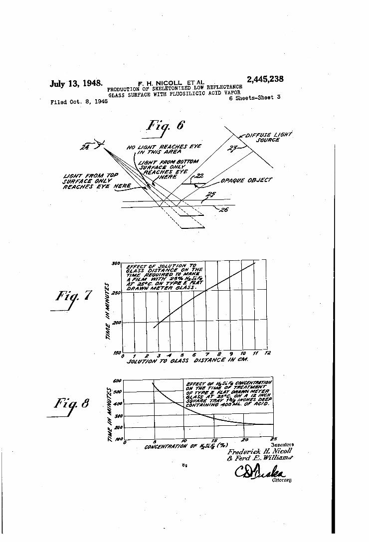
desired characteristics for the treatment of glass; Fig. 6 is a sketch illustrating a method of sepa
rating the reflections from the two surfaces of glass; Fig. '7 illustrates how variations in distance between »the solution and the glass affect the time of treatment; ^ '
Fig. 8 illustrates .the relationship between 'the concentration of HzSiFe and the time of treat
ß ment;
complication which it is desirable to avoid. The ‘ earlier method also involves rather exact control in order to insureuniform gas distribution and concentration at the surface undergoing treat ment, and also to insure conditions suitable for the formation of hard films. The present invention has for its principal ob
ject the provision of an improved method of oper ation which avoids the necessity of maintaining a fixed temperature difference between the treated surface and‘the solution from which the active components are derived. Another object is the provision of an improved
method of operation whereby the concentration and distribution of the active» sas is rendered more uniform, and the conditions for hard film formation are made less critical. A further object is the production of a low
reflective coating which is harder than those .pro duced by former methods- and requires less time for its production. n A still further object of this invention is to
30
35
40
45
50
Fig. 9 ‘shows the linear relation existing-between the logarithm of the concentration and 'the log arithm of the time required to produce a quarter wave film;
Fig. 10 shows the logarithm of the time of treat ment vs. the logarithm of the absolute temper ature;
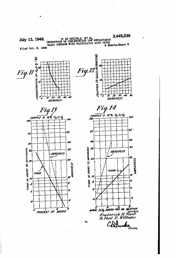
Fig. 11 illustrates the relation of film hardness to acid concentration;
Fig. 12 shows the film hardness as a function of the distance from solution to glass;
Fig. 13 shows the variation of hardness and time of treatment as a function of the amount of concentrated HF (47%) added to an original 16% solution of acid;
Fig. 14 shows the time of treatment vs. and
Fig. 15 shows time of ance of the glass.
Skeletonization as an aid to the reduction of reflection from a transparent body was first dis closed by Blodgett in Physical Review, February 15, 1939. A very thin film of soap was deposited on glass and the film was then treated to dissolve
variation of hardness and the amount o'f added silica;
treatment vs. the reflect

2,445,238 3
out certain components, leaving a skeletal struc ture with air filling the spaces formerly occupied by the dissolved material. Blodgett noted that the spaces and the solid portions must be of molecular dimensions. at least smaller than a Wavelength of light, if transparency is to be re tained. Surface reflections are reduced by the well known interference effect when L.the ñlm thickness is equal to a quarter wavelength of the incident light. As is also well known, the maxi mum reduction of reflection occurs when the in dex of refraction of the film is equal to the square root of the index of the base glass, when viewed in air. The function of the skeletonlzation is to reduce .the index of refraction of the soap film to an approximation of the optimum value. This 15
method has not come into commercial use because . the film is extremely fragile and is easily wiped y olf. The production of a reflection reducing film
by the chemical treatment of the glass surface with an acid solution is also well known. For example, the glass may be immersed in a nitric acid solution. (See U. S. Patent 2,220,862.)A This method, however, is limited to the treatment of certain types of glass which contain a metal, and such glasses inherently have a high index of re fraction. The nitric acid process is >known as “etching" and is distinguished from skeletoniz ing in that in the former case the acid removes only the metallic components of the glass and leaves a surface presumably of solid silica, since in every case the measured index of refraction -which results is simply that of solid silica; where as in the latter case the acid reacts to some ex tent on the silica as well as the non-silicious components to produce a surface layer which has a porous structure of molecular dimensions char
’ acterized by an index of refraction which may be much lower than that of any component of the glass in its solid state. Also to be distinguished from skeletonizing are the various frosting proc esses which treat the interior of glass bulbs, for example. to produce a frosted or opaque surface which disperses the light. Frosting has no util ity in the reduction of reflection since the trans parency of the glass is destroyed. Frosting mere ly pits the surface. with no attempt to produce a surface film having a critical thickness bearing a predetermined relation to a wavelength of light, and since light is dispersed, the dimensions of the surface irregularities Amust be greater than a wavelength of light. In accordance with the present invention it
has been discovered that by substituting fiuosi l'licic acid (HzSiFe) for the hydrofiuoric acid of the earlier' Nicoll vapor method, the necessity of maintaining a temperature difference between the solution and the treated surface is avoided. In addition to greatly simplifying the apparatus required, a coating of superior hardness is ob tained. y
Glass in contact with saturated water vapor is known to have a thin film of water adsorbed on its surface. A‘soluble, so-called ‘i‘white deposit” is formed during the production of the skeletonized film by the hydrofiuoric acid vapor method. This deposit consists of fiuorides and fiuosilicates. Also, water is a product of the reaction between the glass and hydrogen fluoride. These facts in dicate that during the film formation a thin solution, saturated with respect to alkali and alkaline earth fiuorides and fiuosi'licates, exists at the >glass surface, while an inch or two below the glass is a dilute hydroiiuoric acid solution.
20
25
30
85
40
45
55
00
70
Raoult’s law states that the vapor pressure of a solution is lowered in proportion to the molecu lar concentration of the solute dissolved. It is therefore apparent that the solution on the sur face of the glass during treatment will have a lower vapor pressure than pure water at the same temperature due to the dissolved fiuosill cates. If the acid solution and the glass were maintained at the same temperature there would be a vapor flow in the direction of the glass tend ing to increase the water content in the solution on the glass surface. This is due to the'dii’fer ence in vapor pressures. Such a variation in water content on the glass surface produces a soft film or no film at all. The unequal vapor pressures have heretofore been compensated by Y decreasing the temperature of the acid solution to a value a few degrees below that of the glass. This result could be equally well produced by applying Raoult’s law to the acidsolution thus reducing .the vapor pressure of the solution to the desired value by the addition of salts, as described and claimed in a copending applica tion of Nicoll and Williams, Ser. No. 488,938, filed May 28, 1943. If the salt solution on the glass is to remain approximately constant with respect to time it is necessary for the vapor pres sure of the acid solution and the solution on the glass to be approximately the same. Under these conditions the glass will neither become wetter nor dryer as the process of film formation pro ceeds, and hence the best conditions for opera tion are maintained. In fact, it would seem ad visable to select the conditions such that the solution on the glass surface would have a slight ly greater vapory pressure so that some of the water formed during the glass attack would be removed. The use of fluosilicic acid as a source of vapor
for producing low-reflection films on glass came about as a result of considerations regarding the - formation of fluosilicates and the silica film at the glass surface. The reactions occurring at the glass surface may be written in the following Way:
'I'he first reaction indicates the white deposit formation and uses up a molecule of silica for each molecule of metal oxide present. The silica ; which remains will form the skeletonized film if the second reaction does not proceed towards the right. The rate of silica ñlm formation will vary directly ̀ as the first reaction and inversely as the second. It is therefore desirable to promote the first reaction and inhibit the second. On the basis of the Mass Action Law, the second reac tion can b_e “ inhibited by increasing the vapor pressure of SiF4 in the system. This mechanism may explain why increasing the HF vapor pres sure too much fails to increase the speed of film formation and may even result in no production at all. 'I‘his would probably not be the case if the SiF4 vapor increased with the HF. -The present invention may be practiced by
filling a wax-lined copper tray i0, 2" deep by 12" square, with 16% iluosilicic acid I2 to a depth of Va". 'I'he glass I3 to be treated is then placed over the top of the tray preferably with an air tight seal around the edges and covered with a copper plate or lid Il. At a temperature of about
vsinned for the purposes of this discussion
9,445,238
25° C. there is produced in about 41/2 hours a hard ‘low index film of a thickness suitable for minimizing the reflection of green light. A coat ing of ceresine wax is used in the tray to prevent attack by the acid, or it can be coated with sev eral baked layers of Harvel 612C insulating var nish made by the Irvington Company of Irving ton, New Jersey. Metal is specified for the tray i0 and lid il because of its thermal conductiv ity. The conductivity of the tray and lid assists greatly in maintaining temperature uniformity of the glass and solution. While it may not be essential to use metal when the temperature stability of the room is particularly good, there is always a certain amount of dangerfrom drafts causing non-uniformity of temperature over the glass surface. This is the reason for recommend ing the use of metal trays and covers except under conditions that are exceptionally suitable.
Referring to Fig. 2, an alternative arrange ment is shown for eliminating drafts and unequal temperature. It will be seen that/the tray I0 is lined, is provided with the acid solution i2, and is covered by the glass I3 to be treated. In these respects the apparatus of Fig. _2 is similar to that of Fig. »1. The copper plate Il of Fig. 1 is re placed by an inverted tray or lid I1, which is preferably made of metal, and which traps the air in an enclosed space so as to eliminate air currents and maintain a uniform temperature distribution. ' When several small pieces of- >glass are to be
treated, the apparatus of Fig. 3 may be used. In this arrangement the tray I0 is covered by a metal plate I8 which is provided with openings’ I8. The openings are adapted to receive the glass pieces ‘20 to be treated. The several pieces 20 may be supported by nne wires 2|. The suD porting wires may be soldered or otherwise fas tened to the metal plate. This method of treat ing small pieces has been found to give uniform
` films to within 11s" of the edge of the treated sur face. .
The fiuosilicic acid solution is made up from technical quality concentrated acid (usually 30%) , althoughcommercial quality may be satis factory. A concentration of 16 percent by weight is used in general, but as much as 25 percent may be used on some glasses in order to speed up the process. It has been discovered that the HF content of the acid is to a large extent the deter mining factor in the operation of the process, and for best operation the composition of the solution in th'e tray must be kept within certain limits, to produce acceptable low-reflection films. The raw acid from various sources shows consid erable variation in composition. Even from a
~ single source, the composition cannot be relied upon to'remain constant. The tray solution is found to change slowly in composition while it is inservice, presumably because of evaporation and reaction with glass. Thus it is evident that a method of fully char
acterizing and controlling the composition of fluo siiicic acid solutions may be useful in the vapor process of treating glass. Such a method h'as been developed by S. M. Thomsen. It consists of two acidimetric titrations on the sample. Procedures for these titrations will be given, to gether with control operations based on the re sults of the titrations.
_ The ordinary fluosilicic acid is generally speci fled as vbeing 30%. ̀ This is a percentage by weight. These percentage figures will be aban
for two
15
reasons. First, wh‘ile a pound of 30% acid diluted with a pound of water yields a 15% acid, if the 30% acid is diluted instead with an equal volume of water the resulting solution is over 16 %'. ' Sec ond. two solutions may both be 16%, and yet dif fer in composition, because'the acid can vary in silica content. Therefore, the assay will be de fined as what might be called the total acidity, as obtained from the titration II to be described, computed to moles per liter of HzSiFn, assuming 6 equivalents of alkali per mole of HzSiFe. This figure, M, is independent of the silica content, and dilution with an equal volume of water re duces the assay (so defined) or molarity, to half. Commercial 30% acid has ranged from 2.5 to 3.1 molar (moles per liter of HzSiFs) . ; Unlike most acids, fiuorsilicic acid varies in
composition aside from its water content. Spe cifically, the silica content may be less or greater than that demanded by the formula HzSiFs. The silica content _may be specified as a “_silica num ber, S,” so defined in terms of titrations I and 1I, that for the theoretical HzSiFe the number is 1.00, and the number is proportional to silica con tent. Fluosilicic acid in concentrations near 2.5 molar, lfully saturated with silica, has a silica number of 1.18. That is, it contains 18% more silica than the theoretical HzSiFa. Hydrofiuoric
` acid, HF, may be considered to be fluorsilicic acid of silica number 0, since it contains no silica. Consequently, a silica number of less than 1.00 means th‘e presence of free HF. Commercial
. 30% acid from various sources has ranged from 1.03 to 1.18 in silica number.
It should be understood that the silica content _ consists not of free silica, but of fluorinated spe
40
45
50
55
60
70
75
cies such as SiFs=', HzSiFs and probably SiF4. If the vigor of the attack on theglass by the
tray solution is too great, a soft film results. If too low, the resulting film is too high in index, and therefore too low in efllciency. The greater the concentration (assay) and the lower the silica number, th‘e more vigorous the attack. At cer tain combinations of assay and silica number, therefore, a particular glass will produce a film _which will be a chosen compromise between hard ness and emciency. Treating time for a particu lar'glass at a particular temperature is deter mined by the composition of the solution. As seen from the curves for four sheet glasses in Fig. 4, hardness and treating time increase upward and to the left in each case. The dotted line connects combinations which produce films of about ̂ the minimum hardness acceptable as judged by a fingernail test, and these films are near the optimum index of refraction, and there fore rather efficient. These data were obtained »with a "/ß” distance from solution to glass. ' Trays of other dimensions may be expected to display a shift in the values required to produce a given result; deeper trays require more vigorous solu tions. .
Since' it has not previously been known that ‘the silica content of fìuorsilicic acid varies con siderably between different manufacturers, and since the "silica number” controls the success of the vapor treatment, infomation will be given showing how to measure the molarity (Mo) and silica number (So) of the commercial acid, and then how to adjust the raw acid to give a solution having the molarity'of (Mx) and silica number (Sx) desired for the treatment of a particular glass, or for a particular purpose. For acids above 1.5 molar, as are encountered
in the tray process, a 5.00 ml. sample is taken

>mality N (2 to 2.5).
2,445,238 y
7 for analysis. It is delivered from an internally waxed pipette into a Lucite dish.y About 3 gm. (r0.5 gm.) oi' powdered NaF is added. Lumps generally form; these are broken up with a Bake lite rod, and the mixture stirred. Bromthymol blue indicator, l0 drops of 0.1% solution in alco hol, is added, making the mixture a bright yel low. Thel mixture is titrated with NaOH of nor
At the approach of the end point, the color becomes greenish yellow. The end point is taken at the darkening> to a blue of greenish cast. Running past the end point pro duces a royal blue; this color cannot be used for the end point,~ because while it appears with each added drop of alkali, it soon fades to the greenish bluev mentioned. Care must be taken to titrate the acid trapped among the solid par- ‘ ticles; the yellow or yellow-green must not re turn upon stirring. If some of the alkali is run in before the NaF is added, softer lumps or none are formed, and the titration is done more quick ly. Let A=No. of mi. of NaOH solution con sumed. Titration II is performed as a further operation on the same sample. This is the usual assay titration described in
the literature. The blue mixture left after titra tion I, about 15 ml. in volume, is washed into a 600 mi. Pyrex beaker with hot (95° C.) water, and the volume brought to about 300 ml. The solution is now greenish yellow in color. Phenol phthalein indicator (10 drops of 1% solution in alcohol) is added and titration with NaOH con tinued. The solution darkens throughgreen to blue as the end point is approached. The end point is taken as the phenolphthalein turns red; and since this is mixed with the blue of the first indicator, the end point is the appearance of a purple color. The solution is ñnally brought to 95° C. and stirred; if the 'purple color does not fade to blue the titration is completed. Let B=No. of ml. of NaOH solution consumed by the sample, including that used in titration I.
Titration of a 5.00 ml. sample yields the fol lowing data:
N-normality of NaOH A-mL NaOH, titration I B-ml. NaOH, titrations II-i-I
The assay or titre, M, is then
M=%’BN<Í 1%) The titration ratio, is deñned as
R=A/B
from which the silica number, S, is given by
S=3/2 (l-R) (1i-„005)
Designating asMo, So, the composition of the raw acid on hand, or the solution to be adjusted, and as Mx, SKA, the composition to be achieved, the computation will be separated into several steps to avoid complications. ‘
A. Dilution to 2.50 molar. Take Vo ml. of the solution of composition Mu, So, and add water to make the volume V1:
, _ :m
The volume of water required W1 will be
W1=V1Vo
B. Decrease of silica content (if required) from
20
30
35
40
45
50
55
60
65
70
So to Sx. To the V1 ml. of acid (M=2.50, S=S0) add F ml. of 15 N HF as follows:
This makes the volume now V2 ml.:
of nuosincic ac1d,`M=2.5o, s=sa C. Increase of silica content (if required) from
So to Sx. To the V1 ml. of acid (M =,2.50, S=So) add, instead of the HF, Q ml. of silica saturated fluosilicic acid (M=2.50, S=1.18) as follows:
_ Sz-SO Q*V‘(1.1s»s, This makes the volume now V2 m1., thus:
of fluosilicic acid, M=2.50, S=Sa D. Final dilution from M :2.50 to Mx. To the
V2 ml. of acid (M=2.50, S=S1), water is added to increase the volume to Va, thus: _
2. VF( Vl
The amount of water required is W2 ml., thus:
W2=V3V2
The ñnal result is V3 mi. of acid, M :Ma S=Sz, obtained by adding to Vn ml. of the original acid W ml. (=W1+W2) ml. of water and either F ml. of 15 N HF or W ml. of silica saturated 2.5 molar acid. '
These reagents were chosen to have the same assay (by titration II) as the acid (2.50 molar) with which they are to be mixed, to simplify com putaticns. The required 15 N HF is obtained by diluting
a concentrated acid of known titre. The titre is obtained by the conventional titration (using plastic or waxed containers) with NaOH (aboutI 22.5 normal) using phenolphthalein indicator. Thus, for a, 5.00 ml. sample, consuming M ml, of NaOH of normality N, the titre T (normality) of .the HF is as follows:
This reagent may be thought of as 2.50 M fluosiliclc acid from which all of the silica had been removed (silica number :0) . The 48% C. P. hydroñuoric acid has been found
to run close to T=28 normal, and, if this value is assumed, 15 N acid may be prepared by dilut ing 150 ml. of the 48% acid with 130 ml. of water, giving a volume of 280 ml. of 15 normal HF. The 2.50 molar silica saturated ñuosilicic acid
is prepared by suspending hydrated silica in a 2.50 molar i‘luosilicic acid solution for several hours, agitating occasionally and ñltering. Crude silica (powdered sand) dissolves too slowly to be usable.
Fig. 5 is a graph showing (a) the assay (Mo) and silica number (So) of 4 samples of commer cial 30% HzSiFe as received from the manufac turers. »"ample A has a molarity of over 3.0 and a silica content approaching saturation (1.185). Without correction the vapor from this acid would not skeletonize glass. Samples B and C are about the same, M is approximately 2.8 and S is 1.10. From the curves of Fig. 4 it may be seen that without correction as to silica number
2,445,288 _ 9 , - .
a film of h_igh index would result. and tbe silica number preferably should be reduced to a more suitable value as described above. 'l'.'he coin cidence of these samples having'nearly the cor rect silica number explains why skeleton films were produced with these acids. Dilution alone would bring these samples into the region which would produce a usable nlm on certain glasses. Sample D is on the upper edge as to strength but too low in silica number. This results in excessive activity and a soft film is produced. Another method of determining whether a
given sample of acid is suitable is to conduct a series of tests using small cups approximately 2 in. in diameter and ` large tray. 16 percent solutions of the acid are made up and various small quantities of silica are added to another range of samples. A good range to cover in such trial samples is from 0 to l percent HF and from 0 to 100 mg. of powdered silica per 10 cc. of 16 percent solution. About five equal steps for both sets of samples is most suitable and these should suffice for the com mercial acids available. These sample cups are now used to produce a film on the particular glass which it is desired to treat, the glass being placed on the top of the cup. After a period of ten hours or soa number of the cups will have pro duced films and if they have been observed pe riodically it will have been possible to remove all the samples at or near the first minimum of re flection. The results will now show a variation
of the same depth as the'
in time of treatment, hardness, and the efficiency ' of the reduction of reflection. It is necessary at this point to select the most suitable result an-d note the solution which produces ‘- it. The best sample consists of a compromise of the above mentioned factors but it is essential >to obtain low reflection, at most 10 percent of the untreated reflection, and yet retain a fair. degree of hard ness. A hardness corresponding to about 8
x good results
40
strokes with wet rouge using the arrangement de- « scribed in a later paragraph on hardness is prob ably the minimum ,that should be considered. The quality of the selected film should be such that there is very little scattered light under fair ly intense illumination against a'dark background. When the correct composition of the acid has been> decided upon, a quantity of solution is made up sufficient to cover the bottom of the tray to a depth of about 1A; inch. If the tray is deeper than 1% in. then the acid is poured in till the distance from the acid to the glass 15.11/2 in. T'his is the recommended distance between glass and acid for the most satisfactory results.
It is, of course, necessary to maintain losses due to evaporation and when large quantities of glass are being treated it is necessary to replenish the solution due to the loss of acid in treating the glass. The need for this will become appar ent when the'treating time has changed by about 10 to 20 percent. Because of the low vapor pres sure of HF and SiF4 compared with the vapor pressure of H2O, the solutions tend to concen trate themselves so that water must be added as evaporation takes place. ' As the treatment proceeds a white deposit
forms on the glass which gives it a translucent appearance. The amount is a function of the glass composition. ,This must be washed off soon after the glass is removed from the tray, otherwise it remains strongly ad hered to the glass. The time at whichv glass of a given composition
should be removed can be determined by inspec
50
~ `duce reflection is essentially
55
60
10 ' tion after a little experience. In order to do this it is necessary to observe the color of white light reflected from the lower surface of the glass as it is exposed on the tray. This can be done by 0b serving the separate images from the top and
‘ bottom of the glass. Referring to Fig. 6. it can be seen that the images can be separated by look ing at the shadow images of an opaque object Il. illuminated by the light source 23,'whichmay be any source such as an electric light bulb. As seen by the eye 24 the image of the opaque body is ob served to have a black middle portion and a light edge on ' the sides nearer and farther from the observer. The width of this edge depends on the glass 25 thickness and viewingang‘le. The edge farther from the observer is colored by the light from the lower surface 26, and this is the edge for observing the amount of treatment. The white deposit modifies the color of the lower surface and it has been found that the edge which shows the color of the lower surface should appear blue to the eye when the glass is finished if the glass _ has the composition of ordinary window glass. If the white deposit is now washed off with run ning water angl the glass dried. the surface will then appear the desired purple color. Borosilicate crowns and heavy lead glasses ap
pear to have less white deposit in general and thœe are therefore at the minimum for green light when the color with the white deposit on is between purple and blue. ` For many purposes the time of treatment can
be obtained fairly well by timing and correctingv for any average temperature change, if experi ments have already been run on the same type of glass. This assumes that the acid concentration remains constant. It must be remembered that
are only obtained in the neighbor hood cf 25° C. with acid concentrations near 16 percent. 'When a number of trays are used it is desirable to have exactly the same concentration of acid in each tray (preferably obtained by mix ing). If the height of the glass above the acid is the same in each same temperature then inspection of one tray serves to give the time ofremoval for all. Esti mation of the approximate time of treatment can be obtained from a knowledge of the time of treat ment at a givenv temperature for the particular glass used.
Fluosilicic acid vapor treatment of glass -to re a surface treatment
and success therefore depends on the condition of the glass surface. For this reason polished plate glass and fire polished, flat drawn window glass of the same composition nevertheless treat at somewhat different rates. A good, clean surface is essential for obtaining .uniform films free from scattered light. The surface must also be Y dry before treatment (drying with a cloth is suf iicient). One satisfactory method of cleaning is to use Bon Ami or kpowdered chalk. This is ap plied wet, the glass being thoroughly rubbed with
' a cloth, after which the Bon Ami is washed off
of this white deposit . 'l0v
76
before it dries. The glass is then thoroughly dried with a clean cloth. ' A‘brief dip, up .to about 4 min. in 0.5 percent
HF solution, followed by rinsing and drying will usually give a good clean surface if the glass is fairly clean and grease-free before dipping. Too long a dip will visibly etch the glass and ruin the surface. This procedure window glass and is not recommended for pol ished glass. With fresh 'glass this treatment may be successfully used to removeßroller marks.”
tray and they are all at the .
is -best applied. to ‘

2,445,238 . `11 i
Treated glass readily vpicks up oil or grease from contact with' oily or greasy materials and this -tends 'itc remove its low-reflecting properties. In handling the glass it is advisable to avoid such contact and also to avoid lingering Ithe glass. During shipment the glass must be wrapped 'in paper which will not produce spots on the glass after long contact. Glassine envelopes seem to be satisfactory for .this purpose. The treated glass can be cleaned withV water and any non abrasive soap, but care must be taken to re move all the soap from the glass ‘before it is dried with a cloth. 'I‘he treated yglass can be cleaned with any of the common acids if desired. ` 'I'he description which has already been given of the method of producing low-reflection films by the use of iluosillcic acid has indicated its dependence on a number of factors. In order to produce satisfactory films it is desirable to know the eii'ect of the various factors on the yillxn formation. These effects have been investigated fairly exhaustively and the results are given in the following paragraphs.
Errrcr or TRAY Ann
The area of the tray was a factor in the older hydroiluoric acidl vapor method of reducing the renection from glass. In going from a tray of six hundred square inches to ‘three square inches, the time of treatment was increased by about two hundred percent. This eil'ect was probably due to convection effects brought about by the use of _ a temperature difference. In the case of the present iluosilicic acid vapor method, which doesn't require a temperature diiîerence, thetime of reaction increases fby less than two percent over »the previously mentioned range of' tray area. It may be concluded, therefore, that the eii’ect of tray area in the ñuosilicic acid process is negligible and the following data on the> eilect of other variables applied to tray sizes from three square inches to six hundred square inches, un less otherwise specified. Edge eil’ect on the treated glass is proportionately larger onv the small Itrays.
l Erncr or TRAY Hncnr
Because the diiIusion of the fluosiliclo acid vapor from the solution to .the glass is one of the »rate-«limiting processes in film formation, and because the rate of iiow of a substance lvaries in versely with the length of the path of flow; ift would be expected that increasing the distance from the surface of the acid solution'to the glass surface being treated would increase the time of treatment. Experimentally this is found rto be the case,_ _as is shown in Fig. '7 for 25- percent by weight I-hSiFs. The data for this curve were taken on trays three square inches in area. This curve over the 'approximate height range of,2.5 cm. Ito 6 cm. applies to trays up to at least six hundred square inches in area. Above about six centimeters high, convection difli'culties appear in »the case 'of the trays of larger area. > Convec tion currents cause soft non-uniform fllms as well as pronounced changes in the rate of nlm formation. Solùtion-to-glass distances less than 2.5 centimeters also result in poor films, when using pure iluosilicic acid. For .the range of. tray ' heights over which satisfactory ñlms are ob, tained, the time of treatment for Libbey-Owens Ford flat-drawn glass variœ with the solution-to glass distance as is shown in Fig. 7 for. 25 percentt HzSiFs. Other glasses or other conçentmtfiime
10'
15'
20
30
4 32
45
50
55
60
65
70
75
12 of iiuosilicic acidmay result in different absolute' .times of treatment, but the variation of time of' ltreatment with solution-to-glass distance ap‘ proximates the form of the curve of Fig. 7. A glass-to-solution distance oi' 11/2 in. has been found to give »the most. satisfactory films with most glasses, when it is desired to keep the-time of treatment as short as is consistent with good films.
Errlcr or CoNcnNrnArroN
The concentration of the ñuosilicic acid wed as a source of hydrogen fluoride and silicon .tetrafluoride gas ail’ects fboth the rate of the reaction and the quality of the resulting film. Theoretically this eiIect is due to two reasons. First, increasing the concentration of iiuosilicic acid results in a decrease in the vapor pressure of water because the vanor pressure of each con stituent is proportional to its mole fraction. This decrease _in the water vapor pressure de creases the amount of adsorbed water on the glass surface so that the resulting film is harder and no temperature diil'erence is required. Sec ond, increasing the concentration of iiuosilicic acid increases the concentration in the vapor of hydrogen fluoride and silicon tetrailuoride inde pendently. These substances each aiïect the rate of film formation in different-ways. The in creased amount of hydrogen fluoride present at the higher concentration produces a more rapid attack on the glass while the silicon tetrailuoride more eiliciently inhibits the attack on_ silica at higher concentrations. `Solutions of iluosilicic
I acid concentration less than 13 percent by weight have la greater ratio of HF molecules to, SiF4 molecules in the vapor than that corresponding to HzSiFa, whereas solutions having a concentra tion greater than 13.3 percent have a smaller ratio of HF molecules to SiFl molecules in the vapor than that corresponding -to HaSiFs. Be cause of these varied eil'ects of fluosillcic acid concentration on the rate of ñlm formation, the experimental dependence of rate of film forma- . tion on concentration follows no simple linear behavior but is lbest shown by Fig. 8. '
It is possible to determine the order of the re-_ action involved in a process from the slope of the’ curve of concentration against time. The order of the reaction is given by n in the expres sion
In the film forming process the concentration changes only slightly as the ñlm is formed, and so it is more convenient to obtain the order of the reaction from the relation between the time to complete a definite fraction of the reaction and the concentration. 'I'he order of the re action n is given by the relation
1 To» CTP-1
which is derived from the above expression. In the case of film formation T is the time to pro duce a skeletonized silica film 1A; wavelength thick. Taking logarithme of both sides of this equation, the linear relation of the logarithm of the concentration and the logarithm of the time of treatment shown` in Fig. 9 is explained. The slope of this curve is n-l, giving a value of 5/3 for n. If the process of iilm formation were a simple one, the order oi the reaction would be

' aumen
13 an integer. The simultaneous occurrence of side reactions. consecutive reactions. or opposing re actions with velocity constants of the same order of magnitude as the velocity constant of the main reaction are known to lead to deviations ot the order of the main reaction from an integer. Alsol ionic ¿reactions are known to have velocities which are dependent on the concentrations of all the electrolytes in the solution whether they take part in the reaction or not. It is therefore most likely that the order of the reaction is represent ed by the nearest integer to that obtained from the slope of the curve. This indicates that the process of illm formation is a second order re action, which means that the slowest step in the process of film formation involves two molecules of iluosilicic acid. A~possible mechanism satis i’ylng this requirement is shown by the equation:
Experimentally it has been found that below about 5 per cent fluosllicic acid large droplets are prone to form on the glass because'of the high water vapor pressure. This produces soft films. Above about 25 percent iluosilicic acid, the tend ency is to form visible etching and crystals. Crystal formation is particularly apt to- occur when high i‘iuosilicic acid concentrationvis cou pled with high temperature. The limits of con centration vover which satisfactory results are obtained varies with the glass composition and surface structure. For example, Pittsburgh window glass which is air-cooled without being drawn over rollers will not treat with 25 per cent fluosilicic acid, while Pittsburgh plate glass of the same gross composition but of different sur face structure will treat satisfactorily with this concentration. A 'number of sheet glasses and various optical glasses treat most satisfactorily with 16 percent by weight HzSiFs in which the free HF in solution is approximately zero.
Errlcr or Tnurnnams
Small temperature changes produce quite large effects on the time of treatment. At 25° C.; for example, 10 percent decrease in time of treatment, while a temperature drop of 1° C. results in a 10 per cent increase in the timeoi' treatment. The temperature Vdependence of time of treatment is shown in Fig. 10 for 16 percent and 25 percent iluosilicic acid over the temperature range of 0° C. to 45° C. At .both concentrations the curve of the log of the time of treatment plotted against the reciprocal of the absolute temperature ap proximates a straight line. ‘This indicates that
a temperature rise of 1° C. results in a '
Il
50
65
the heat of Vactivation for the rate-limiting proc- » ess is only slightly temperature dependent. Also, the curves for the 16 per cent and the 25 per cent fiuosilicic acid being parallel indicatesthat the heat of activation is only slightly dependent on concentration over this range. From the slope of the curve, the heat of activation can be calculated from the formula:
l d (r)
and equals 16 K' cal. ,_ Experlmentally at temperatures other than
room temperature, diillculty in keeping glass and tray at constant, uniform temperature results in convection diillculties. At high temperatures such as 45° C. the increased speed of the process
70
4Lor` 12-14 o». window'
is more than compensated by the inconvenience of operation.
Dnraxmnecr: or Haammss on Vaarous Fac‘rons
The hardness o! the nlm produced by the iluo silicic acid vapor process is dependent on type of glass, concentration of acid and height of the tray. Table 1 gives a rough comparison of the hardness of illm on various kinds of glass.
Table i
Glass Process ’ Hardness
M in. Pittsburgh platew.. LOF 12-14 oz. window
16% Hisir. ............ __`. .___.do .................. _.
___..do .................. _.
-_-..do .................. __
Ethylene glycol and HF. _
1% HF with temp. dim... L F 12-14 oz. window glass.
These results were obtained on a 1‘/2 in. deep tray using 16 percent HaSiFa and were deter mined by measuring the number of polishing strokes necessary to remove the illm using a felt pad and rouge. A weight of 380 gms. was used to press a cork-backed felt pad onto the glass. The pad was 1 in. in diameter and it was moved slowly back and forth by hand, the glass being wet with a mixture of rouge and water. Strokes were then counted as the pad moved for ward or backward until the film was fairly well removed. These measurements give satisfactory results when used on the same typev of 111m but are not so good when comparing films of differ ent structures. The measurements of Table 1 were made with 16 percent HzSiFs at 25°' C. using a tray with solution-to-glass distance of 3.5 cm. In general, the hardness of the illm seems to
be greater the longer the time of treatment. This fact is exempliiled by the curves of hard ness vs. concentration and hardness vs. tray depth which are shown in Figs. 11 and 12, re spectively. These results were obtained using the felt pad and rouge polishing method. ’I'he curve for varying concentrations was obtained
' on 5.3 cm. diameter cups for a height‘of 2 inches using Libbey-Owens-Ford meter glass. The re sults for varyingheight were obtained on similar glass and cups using ̀ an acid concentration of 24 percent. It can be seen from the results that it is essential to arrive at a compromise between hardness and time of treatment. This we believe is best reachedvby using a tray 11/2 in. deep with a concentration of 16 per cent.
All the results described so far have been ob tained by the use of fiuosilicic acid in which the HF and SiFl are present in solution correspond ing to the composition of HzSiFa. It was soon found that not all commercial iluosilicic acid would produce ya satisfactory film on glass. Ow ing to different methods of preparation, some of the acid had too little HF in it. in other words an excess of silica (most probably as SiFi) , while othermakes of acid had too much HF. Experi ments showed that both these makes of acid could be made to work satisfactorily by adding suf lflcient HF or silica to bring the HF concentration back to the correct working value. Time oi treat ment, hardness, and the index of the illm are all dependent on the HF content. It has been pointed out earlier, in the procedure for treating

must be added is to do a series
2,445,288 „ 15
glass with fluosilicic acid, that the best method of determining the quantity of silica or HF that
of experiments in small cups.
Fig. 13 shows the results of such a series of experiments on Du Pont commercial fluosilicic acid. Two approximately straight lines show the relation of hardness and times of treatment as a function of the amount of concentrated HF (47%) added to the 16 percent solution of Du Pont acid. These results are for Libbey-Owens Ford window glass. As the HF content increases the hardness decreases and the time of treatment decreases. When about 2.5 percent HF has been added the hardness and the time of treatment are approximately the same"as we would get if we had used 16 percent C. P. Baker ñuosilicic acid with no HF added. The Du Pont acid there fore had the equivalent of about 2.5 percent neg ative HF. For low values of the HF content where the time of treatment is long and the film is very hard the index of the nlm is relatively high and the reduction in reflection is not very great. This corresponds to a silica film which is only slightly skeletonized or in whichv the skeleton is filled up with some material of greater index than air. For high-values of HF content the process is much more rapid but the iilm is soft. Fig. 14 shows the results obtained by adding
various amounts of silica to C. P. Baker ñuosiiicic acid. These results fit in with those just de scribed, and time of treatment and hardness in creases with increasing amounts of silica. The index of the film also increases with the addi tion of silica to the acid solution. The results are for Libbey-Owens-Ford -window glass. Time of treatment is given by the continuous curve and the dotted line gives _the results for hardness.
It has been mentioned earlier that satisfac tory films could never be obtained at solution-to glass heights less than 1 inch when using 16 percent iiuosilicic acid. In fact it was observed that experimentally it Was not possible to obtain good ñlms at lower heights even with other con centrations. In the experiments on adding silica to Baker acid it was found that the addition of silica in small quantities made it possible to obtain satisfactory ñlms at heights as low as one quarter inch. It was also found that although concentrations of Baker C. P. acid greater than 25 percent would not produce satisfactory ñlms, the addition of silica made it possible to use concen trations as great as are available, viz. 30 percent. Due to the addition of silica, however, the time` of treatment was still relatively long. The above experiments indicate the important
role that is played by the HF in the iiuosilicic acid solution. The correct quantity is best determined by experiment and in general it has been found that the best results on the majority of common glasses are obtained when the HF content corre sponds quite closely to that present in pure HzSiFs.. In addition it seems most desirable to use a tray height of 1 1/2 inches and a treating time not less than about four hours at 25° C.
EFFECT or GLAss COMPOSITION AND TYPE
The fiuosilicic acid vapor process has been used to _treat a large number of glasses ranging from crowns to heavy fiints. Time of treatment is a function ofthe composition of the glass and Table 2 gives the time of treatment of a number of different glasses, some of which are rouge pol ished and some are fire polished.
10
20
25
Table 2 Approximate relative treating times of various glasses. 16% HiBiF‘,
25° C., tray l2 x ̀ 12 in., glass to liqu d 1% in.)
4’l‘irne to ist Glass Minimum in
Minutes
X-ray protection glass, polished .................... ._ 110 Barium flint, polished ______________________________ __ 215 Dense barium crown, olished _____________________ __ 225 Borosiiicate crown, po ished ............... ._ 240
L. 0. F. 12-14 oz. picture glass, ill'eälolishedA 240 M in. Pittsburgh plate, polished an herculit 240 L. O. F. single strength, fire polished ...... _. 240 L. 0. F. double strength, lire polished ........ _ _ ‘_.. 270 is in. Pittsburgh plate polished. ___ 270 56 in. L. O. F. plate. po ished. 270 54 in. Pittsburgh plate, Polish 270 M in. L. plate, po lshed. 270 Spectacle crown. xpolish ...__ ._ ............. .. 270 Dense flint, pol ed ............................... _. 280 is in. Pittsburgh window glass, fire polished. ____ _. 415
The conditions under which the results were ob tained are given at the top of the table. It can be seen that X-ray glass treats the most quickly and Pittsburgh window glass the most slowly. This latter glass is very similar in composition to the other Window glasses but the annealing process is so different that the treating time is greatly affected. Pyrex cannot be considered as
e treating satisfactorily although some samples
30
35
40
60
65
70
have given films under special conditions in about 19 hours. Fused, polished silica has never given a satisfactory film and in fact has shown no evi dence of any film whatever.
THIcxNsss-Tmn RELATIONS
Fig. 15 shows the relation betwen time of treat ment and the measured reflection of the glass. The reflection was measured by the combination of a tungsten light source having negligible emis sion in the violet and a 929 photocell having neg ligible sensitivity in the red. This arrangement is most sensitive to the green and corresponds to the eye sensitivity. The colors recorded along the curve are those observed visually after the white deposit has been removed. This curve indicates that a time variation of about 6 percent may be allowed from one piece to another without vary ing the reflection of the finished glass by too large an amount. This, of course, assumes that the concentration remains constant, and also the temperature. What we claim is: Y
1. The method of reducing the index of refrac tion of a glass surface with an acid vapor derived from a ñuosllicic acid solution having between 3% and 10% by weight more silica than called for by the theoretical proportions of the formula HzSiFs, which includes the step of subjecting a surface of said glass to said vapor, while maintain ingsaid glass and said vapor at substantially the same temperature. v -
2. The method of reducing the index of refrac tion of a glass surface with an acid vapor derived from a fluosiliclc acid solution having between 3% ’and4 10% by weight more silica than called for by the theoretical proportions of the formula HzSiFs, and a molarity between 1 and 2.5, which includes the step of subjecting a surface of said glass to said vapor, while maintaining said glass and said vapor at substantially the same tempera ture;
3. The method of reducing the index of refrac tion of a glass surface with an acid vapor de rived from a ñuosilicic acid solution having be tween 3% and 10% by weight more silica than

2,445,238 17
called for by the theoretical proportions of the formula HzSiFé, and a molarity between 1 and 2.5, which includes the steps of exposing a surface of said glass to'vapor emanating from said solution in a substantially air-tight container. maintaining a uniform distance at all points on said surface between said surface and said solution, main taining said glass and said' solution at substan tially the same temperature, and continuing said exposure until the index of refraction of said sur face has been substantially reduced.
4. The method of reducing the index of refrac tion of a glass surface which comprises treating said surface with iiuosilicic acid vapor equivalent to that existing in a closed chamber at a dis tance approximately 11/2 inches from an aqueous
l0
solution of fiuosilicic acid having a molarity be- . tween 1 and 2.5 and a silica number between 1.03 and 1.10, and continuing said treatment until a purple interference color is observed when said surface is viewed inv white light.
5. The method of producing a low reilection transparent surface on glass which includes the step of skeletonizing a surface layer of said glass to a depth approximating a quarter wavelength ‘of a component of visible light, or an odd integral multiple thereof, with gas emanated from a solu tion of ñuosilicie acid having a molarity between the approximate limits of 1 and 2.5 and a silica number between the approximate limits of 1.03 and 1.10 while maintaining said glass and said solution at approximately room temperature and continuing said skeletonlzation until the index of
refraction of saidsuriace is of the order of the square root of the index of refraction of the un treated glass. s .
6. The method set forth in claim 5 which in cludes the additional step of maintaining a 11/2 inch spacing between the surface of said glass and said solution.
'1. The method of producing a low reflection transparent surface on glass by means of vapor emanated from a solution of ñuosilicic acid which comprises adjusting the concentration of said so lution to a molarity between the approximate lim its of 1 and 2.5, adjusting the silica number of said solution to a value between the approximate lim its of 1.03 to 1.10, exposing said glass to the vapor emanated from said solution in the absence of cir culating air. and continuing said exposure until a purple interference color is observed when said surface is observed in white ligh .
FREDERICK H. NICOLL. FERD E. WILLIAMS.
_ REFERENCES CITED
The following references are of record in the fue of this patent:
UNITED STATES PATENTS
Number Name Date 254,263 Bitterlin _________ __ Feb. 28, 1882
1,565,869 Straw ____ _; ______ _- Dec. 15, 1925 . 2,215,039 Hood ____________ .__ Sept. 17, 1940 2,337,460 French .......... _.- Dec. 21, 1943 2,410,300 Nicoli ____________ __ oct. 29, 1946