journal of 5, s urface-micromachined components r...
TRANSCRIPT

I O JOURNAL OF MICROELECTROMECHANICAL SYSTEMS, VOL. 5 , NO. 1, MARCH 1996
S urface-Micromachined Components r Articulated Microrolbot s
Richard Yeh, Ezekiel J. J. Kruglick, and Knstofer S. J. Pister, Member, IEEE
Abstract-A class of articulated micromanipulator robots with multiple degrees of freedom, workspaces on the order of a cubic millimeter, and payloads on the order of a milligram are proposed. Rigid links, mechanical couplings, and large-force, large-displacement micromotors have been created. Hollow tri- angular beams made from rotated microhinged polysilicon plates with polysilicon locks can withstand axial loads of up to 2.6 gm. Mechanical couplings with sliding mechanisms are used to rotate hinged structures off the substrate. The typical frictional force observed is approximately 2 pN. Linear electrostatic stepper motors with an estimated force of 6.5 ,UN at 35 V and a travel of 40 pm have also been demonstrated. [160]
I I base
I. INTRODUCTION
HERE are many approaches to developing microrobots [I]-[7]. One of the more successful approaches can be
found in insects, which have articulated limbs. Suzuki et al. introduced the concept of creating insect-like microrobots with exoskeletons made from polysilicon plates and flexible poly- imide joints [SI. We continue in that direction by developing a class of articulated microrobots using hollow triangular beams (HTB’s) as links, microhinges [8], 191 as revolute joints, and linear electrostatic stepper motors for actuation [lo], [ll]. Fig. 1 shows a diagram of the proposed articulated manipulator that consists of robot links connected by revolute joints.
11. FABRICATION PROCESS
All components for this project are fabricated using the MUMP’s process [ 121. This commercially available process is described in detail elsewhere [13], but a quick description of the process layers is as follows:
0 Silicon substrate. * 0.5-pm-thick silicon nitride covers the entire chip (can
not be patterned). e 0.5-pm-thick polysilicon used for electrode layer (“poly
0” layer). * 2-pm-thick PSG (“ox 1” layer, patterned for contacts and
dimples). 2-pm-thick polysilicon (“poly 1” layer).
e 0.S-pm-thick PSG (“ox 2” layer, patterned for contacts). 0 1 .S-pm-thick polysilicon (“poly 2” layer). * 0.5-pm-thick goldkhrome (“metal” layer).
Manuscript received June 24, 1995; revised October 24, 1995. Subject Editor, E. Obermeier. This work was supported in part by NSF and ARPA under Award IRI- 9321718.
The authors are with the Department of Electrical Engineering, University of Califomia, Los Angeles, CA 90095-1594 USA.
Publisher Item Identifier S 1057-7157(96)01465-5.
I
Fig. 1. links.
Diagram of an articulated manipulator with revolute joints and robot
After fabrication, the chips are etched in 49% hydrofluoric acid to etch away the sacrificial oxides (ox 1 and ox 2). To reduce stiction between the polysilicon structures and the substrate, the chips are dried in supercritical carbon dioxide after the sacrificial etch [16].
111. MODULAR RIGID MICROROBOTIC LINKS
A surface micromachined link, made from thin film polysil- icon, must be rigid and strong enough to support the weight of its payload and also have the requisite shape to allow joints to have independent axes of rotation. HTB’s have been designed and tested to satisfy these conditions.
A. Design Fig. 2(a) shows the CAD layout of one version of an
HTB. This HTB is designed with three plates connected with scissor hinges [Fig. 3(a)], which allow two plates to rotate with respect to one another. This allows the use of three-axes micromanipulators with probe tips to fold the two side plates up and over the center plate, creating a hollow triangular beam. The two side plates have snaplocks (Fig. 4) along the top edges to fasten the plates in position. Fig. 2(b) shows a SEM picture of an assembled HTB with substrate hinges [Fig. 3(b)] that allow the HTB to be rotated off of the substrate. This HTB has a right-triangular cross section. Fig. S shows HTB’s that have been rotated off of the substrate after assembly.
B. Strength and Stifiess
To find the strength of HTB’s in the axial direction, we performed a loading test on several chips. In these tests, a
1057-7157/96$05.00 0 1996 IEEE

11 YEH et al.: SURFACE-MICROMACHINED COMPONENTS FOR AFXICULATED MICROROBOTS
snaplocks
scissor --s
M / hinges
(b)
Fig. 2. HTB’s. (a) IC CAD layout of an HTB with scissor hinges, substrate hinges, snaplocks, center plate, and side plates. This version has a right triangular cross section. (b) SEM picture of an HTB. A buckled beam jack (also known as a micro jack) [14] is used as an assembly aid.
glass box is placed on top of four 432-pIm-tall, rotated HTB’s (Fig. 6). One of the four HTB’s was viewed and videotaped from the top view through the glass box with a microscope and TVNCR setup. Water was then injected slowly from a syringe into the glass box until the HTIB’s collapsed.
Assuming the video cassette recorder records at a speed of 30 frames per second, an HTB typically collapses in about 100 ms under a critical load. At the critical load, the snaplocks usually break first, followed by the scissor hinges. After the scissor hinges break, the side plates separate from the center plate, leaving only the center plate to hold the load. Finally, the center plate breaks. Inspection after the loading tests indicate that most center plates break along the same points [Fig. 7(a)]. Fig. 7(b) shows the remains of the four center plates after a loading test. Note that the center plates broke in approximately the same place, while all the substrate hinges remained intact. In separate tests, total loads from 8.7-10.2 gm have been observed at failure. If we dissociated the four HTIB’s into the
(b)
Fig. 3. Two versions of microhinges. (a) Sciss,or hinges allow two released structures to rotate with respect to each other. (b) Substrate hinges allow a released structure to rotate out of the plane of the substrate.
12 plates that made up these four HTB’s and repeated the test, the calculated buckling load would only be 0.4 gm.
Similarly, we expect the HTB to have a higher stiffness compared to flat beams. A clamped-free flat polysilicon beam 1 mm long, 100 pm wide, and 2 pm thick. has a spring constant of approximately 0.04 N/m under small deflections. If we could create an HTB with rigid corne:rs, however, the spring constant would be increased to 1400 PUm. Since in reality the HTB does not have rigid comers due to the snaplocks and scissor hinges, we expect the HTB lo be stiffer than a flat beam though not as stiff as an HTB with rigid corners.
C. Articulated Joints and Multiple DOF In addition to the increase in strength and stiffness, the HTB
also simplifies the design of multiple degree of freedom (DOF) structures. Each end of the HTB has three edges available for the placement of microhinge joints. Ely placing a joint at the correct edges in a series of HTB’s, a manipulator with multiple

12 JOURNAL OF MICROELECTROMECHANICAL SYSTEMS, VOL. 5 , NO. 1, MARCH 1996
(b)
Two versions of snaplocks, which fasten the HTB plates. Fig. 4.
DOF can be created. If the links have a right triangular cross section as shown in Fig. 2(b), then the manipulator could have initially orthogonal axes of rotation.
Since scissor hinges are used as revolute joints, their max- imum angles of rotation affect the workspace of the manipu- lator. Various versions of microhinge designs gave measured maximum angles of rotation ranging from 11 1-146". Rotation past the maximum angles of rotation is still possible as the two polysilicon plates connected by the scissor hinges bend elastically.
To give an estimate of the critical load on these scissor hinges, HTB's were tested on a standard probe station to fail- ure. In these tests, unassembled HTB's (with right triangular cross sections) were rotated 90" from the substrate (Fig. 8). The center plate was held in position by two probe tips while the longer of the two side plates was rotated to the maximum angle then deflected slowly until failure. Force was applied to the free edge of the side plate. By measuring the deflection of the side date (assuming minimal center date bending). a
Fig. 5. HTB's rotated by 90° (foreground) with respect to the substrate. A comb-drive resonator is located at the lower-right comer of the picture for size comparison.
HTB rotated by 90'
test chip
Fig. 6. Loading test on four comer HTB's.
Fig. 7. Remains of four comer HTB's after collapse. (a) a CAD layout of an HTB showing typical location of fracture. (b) Remains of H'IB's after a loading test.
force of roughly 1000 pN (equivalent to the weight of a 1 cm2 silicon die) was estimated before the hinges broke.
IV. MECHANICAL COUPLINGS
Mechanical couplings could be the most complex structures to design and assemble on a microrobot built from a planar process. Our approach is to design simple modular components as building blocks. One such component is a planar four-bar linkage made from a lever arm (hinged plate), push-rod, and sliding shuttle [Fig. 9(a)]. Another component is a spatial four-
" o,, bar linkage made by coupling two planar four-bar linkages

YEH et al.: SURFACE-MICROMACHINED COMPONENTS FOR ARTICULATED MICROROBOTS 13
TO
(c) ( 4 (e)
Fig. 8. deflection is reached. (d) Deflect side plate slowly. (e) Scissor hinges break.
Test procedure of scissor hinges. (a) Uiiassembled HTB. (h) Rotate HTB plates to 90’ off the substrate. (c) Rotale side plate until maximum
Fig. 9. SEM pictures of mechanical couplings constructed froim lever arms, push-rods, and shuttles. (a) Planar four-bar linkages. (b) Spatial four-bar linkages.
[Fig. 9(b)]. We have demonstrated this concept by rotating a 1-DOF link using a sliding shuttle and a push-rod as a simple mechanical coupling (Fig. 10). Fig. l l(a) shows another design where a 1-DOF link is connected to a 350- pm-long lever arm, push-rod, and shuttle. When the shuttle is pulled, the lever arm and the attached link rotates [Fig. 1 l(b)l.
A. Modular Design for Multiple DOF Since mechanical couplings connect actuators lo the artic-
ulated structure, the placement of the actuators directly affect the design of the mechanical couplings. There are two likely places on chip where we can place actuators: 1 ) inside the robot links (internally-mounted) and 2) on the substrate (base- mounted). Unlike conventional robotics where the actuators significantly increase the mass and inertia of the manipulator,
the mass of microactuators (a few n,anugrams) is negligible compared to typical milligram loads [10]. Subsequently, our designs are based on what is most fieaijible to fabricate and assemble with the current technology. With the MUMP’s process, it is difficult to place actuators inside of HTB’s due to the lack of electrical isolation in 1a.yers poly 1 and poly 2, so we have designed mechanical couplings for base-mounted actuators.
Lever arms, push-rods, and sliding, shuttles could be used to create building block components for mechanical coupling. From these components, modular mllltlple DOF mechanical couplings could be created (Fig. 12). The force that originates from the actuators on the substrate musf be transmitted to the links on the microrobot. The actuators would be coupled to a lever arm on the substrate to help increase the mechanical

14 JOURNAL OF MICROELECTROMECHANICAL SYSTEMS, VOL. 5, NO. 1, MARCH 1996
Force I
I Mechanical Coupling I Fig. 12. Modular design of multiple DOF mechanical coupling
joint
from next link Fig. 10. SEM picture of an HTB rotated with a push-rod and shuttle
/ linkn-1 2 link n
joint
link n+l
hinges /
hiniees
(b)
Fig. 11. A 1-DOF link with a lever arm, push-rod, and shuttle for mechanical coupling. (a) SEM picture of a lever arm coupled to an HTB for mechanical coupling. A leaf spring latch [8] inside the HTB and scissor hinges connect the HTB to the lever arm. (bj Diagram of the structure in (a).
advantage. The force would then be transmitted through a force feedthrough, constructed from a series of modularly designed four-bar linkages (Fig. 13). The force feedthrough will run inside the HTB’s, transmitting force across HTB’s without hindering their motion. The force feedthrough would transmit the actuator to a ligament coupling (Fig. 14), which would apply the force at the target link. Each link would have its own
Fig. 13. force to be transmitted across an HTB.
Diagram of a modular force feedthrough building block that allows
jojnt
connector
- - link n-1 I linkn
Fig. 14. an HTB.
Diagram of a ligament linkage that allows a remote force to move
set of mechanical couplings (lever arm, force feedthroughs, and ligament) and actuator.
B. Friction
To use these push-rods, shuttles, and lever arms as mechani- cal couplings, an actuator must be able to overcome the friction between the moving parts. As previously mentioned, the mass of our mechanical coupling test structures is estimated to be on the order of a few pgm (a few tens of nN). For such small masses, the friction is no longer dependent on the mass of the structures, but rather on the adhesive forces between the surfaces [ 151. Preliminary tests on friction requirements were conducted on the following test structures:
1) shuttle 2) shuttle + push-rod 3) shuttle + push-rod + lever arm [Fig. 9(a)]
YEH et al.: SURFACE-MICROMACHINED COMPONENTS FOR ARTICULATED MICROROBOTS 15
4) shuttle + push-rod + HTB (Fig. 10) 5 ) shuttle + push-rod + lever arm $. HTB (Fig. 11). Applied forces were estimated by measuring the: deflection
of a serpentine spring attached to the shuttle. To reduce friction from surface liquid adsorption, all sampl'es were dehydrated in an oven at 12OOC for 45 min. The typical static friction for all the different test structures was approximately 2 pN, despite the differences in mass between each of the test structures and the angles of rotation.
V. ACTUATION The mechanical couplings described in Section IV can
be used to control robotic links by sliding shutt1,es linearly on the substrate. In order to slide the shuttles, we need actuators with large force and large displacements By taking advantage of the resolution of standard photolithography, we have created gap-closing electrostatic actuators thiat produce micronewtons of force in a few hundred square pm of chip area. Electrostatic actuators consume liess power compared to thermal and magnetic actuators, but high forces are only produced when the displacement is small. To produce large displacements, we have created a stepper motoir that uses gap-closing actuators in an attachmenlldetachmeint stepping cycle.
A. Gap-Closing Electrostatic Actuators
A simple gap-closing actuator has two beams separated by a gap. In our designs, one beam (stator) is anchored to an electrode (poly 0), while the other beam (rotor) is suspended over another electrode (ground plane) by a folded spring. The electrostatic force between the stator and rotor beiims is
(4- 1)
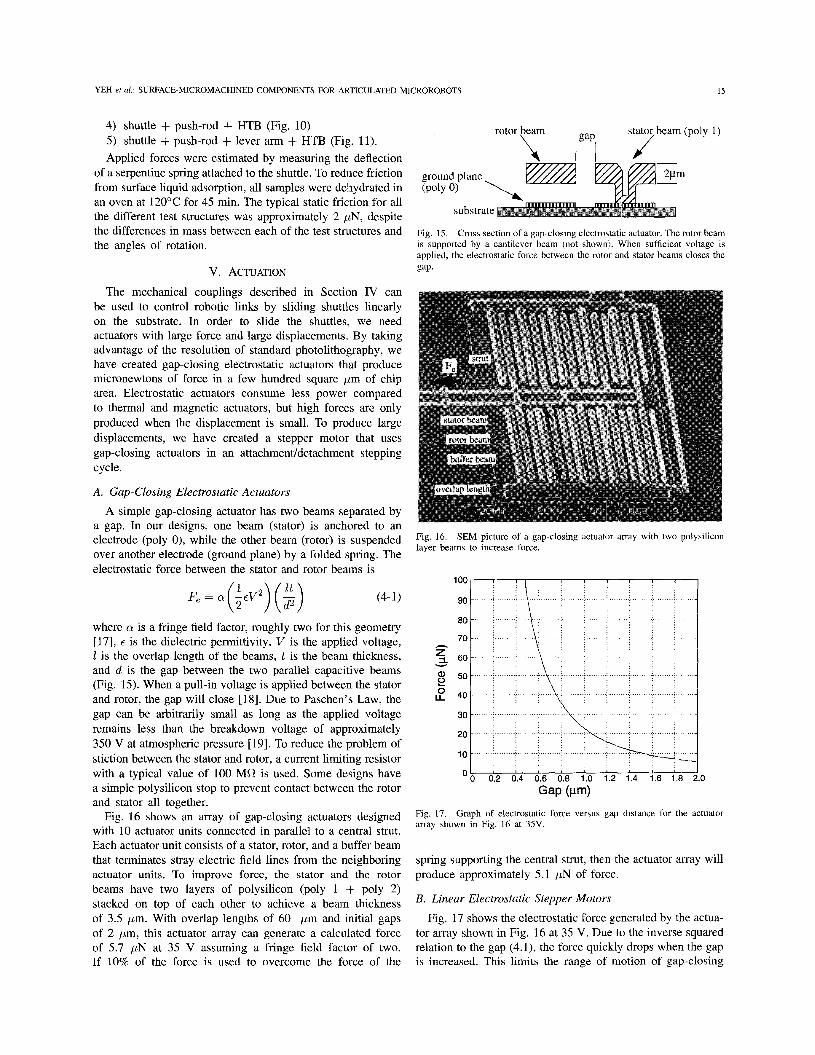
where Q is a fringe field factor, roughly two for this geometry [17], t is the dielectric permittivity, V is the applied voltage, 1 is the overlap length of the beams, t is the beam thickness, and d is the gap between the two parallel capacitive beams (Fig. 15). When a pull-in voltage is applied between the stator and rotor, the gap will close [18]. Due to Paschen's Law, the gap can be arbitrarily small as long as the applied voltage remains less than the breakdown voltage of approximately 350 V at atmospheric pressure [19]. To reduce the problem of stiction between the stator and rotor, a current limiting resistor with a typical value of 100 MR is used. Some designs have a simple polysilicon stop to prevent contact between the rotor and stator all together.
Fig. 16 shows an array of gap-closing actuators designed with 10 actuator units connected in parallel to a central strut. Each actuator unit consists of a stator, rotor, and a buffer beam that terminates stray electric field lines from the neighboring actuator units. To improve force, the stator and the rotor beams have two layers of polysilicon (poly 1 + poly 2) stacked on top of each other to achieve a beam thickness of 3.5 pm. With overlap lengths of 60 pm and initial gaps of 2 pm, this actuator array can generate a calculated force of 5.7 pN at 35 V assuming a fringe field factor of two. If 10% of the force is used to overcome the force of the
stator beam (poly 1) I gap, /
rotor beam \ I I 1 J
ground plane
substrate
Fig. 15. Cross section of a gap-closing electrostatic actuator. The rotor beam is supported by a cantilever beam (not shown',. When sufficient voltage is applied, the electrostatic force between the rotor and stator beams closes the gap.
Fig. 16. layer beams to increase force.
SEM picture of a gap-closing actuator :anay with two polysilicon
O b 0.2 0.4 0.6 0.8 i.0 1.2 1.4 1.6 1.8 2.0
Gap (Pm) Fig. 17. array shown in Fig. 16 at 35V.
Graph of electrostatic force versus gap distance for the actuator
spring supporting the central strut, then the actuator array will produce approximately 5.1 bN of force.
B. Linear Electrostatic Stepper Moto,rs
Fig. 17 shows the electrostatic force generated by the actua- tor array shown in Fig. 16 at 35 V. Due to the inverse squared relation to the gap (4. l), the force quickly drops when the gap is increased. This limits the range of motion of gap-closing
16 JOURNAL OF MICROELECTROMECHANICAL SYSTEMS, VOL. 5 , NO. 1, MARCH 1996
/ left shoe U \ right shoe
f
U U
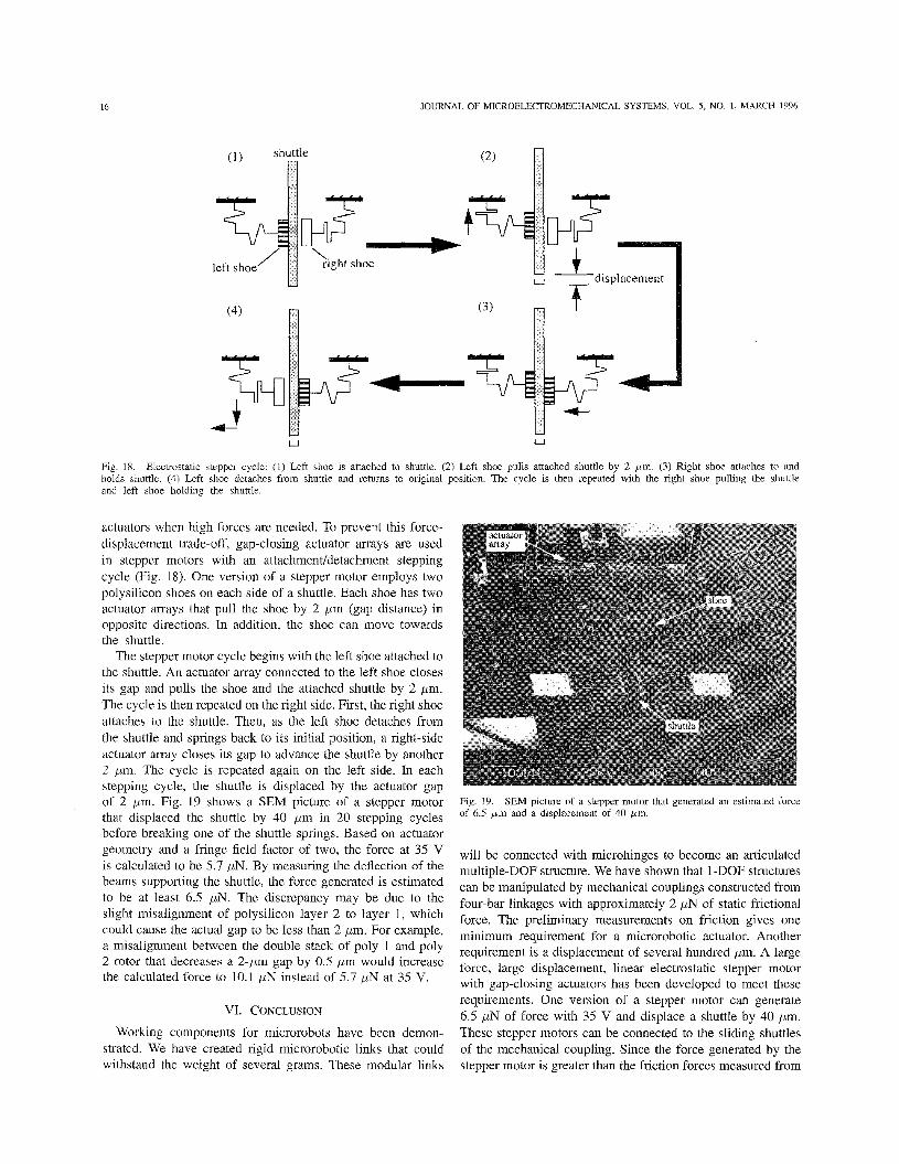
Fig. 18. Electrostatic stepper cycle: (1) Left shoe is attached to shuttle. (2) Left shoe pulls attached shuttle by 2 pm. (3) Right shoe attaches to and holds shuttle. (4) Left shoe detaches from shuttle and retums to original position. The cycle is then repeated with the right shoe pulling the shuttle and left shoe holding the shuttle.
actuators when high forces are needed. To prevent this force- displacement trade-off, gap-closing actuator arrays are used in stepper motors with an attachmenvdetachment stepping cycle (Fig. 18). One version of a stepper motor employs two polysilicon shoes on each side of a shuttle. Each shoe has two actuator arrays that pull the shoe by 2 pm (gap distance) in opposite directions. In addition, the shoe can move towards the shuttle.
The stepper motor cycle begins with the left shoe attached to the shuttle. An actuator array connected to the left shoe closes its gap and pulls the shoe and the attached shuttle by 2 pm. The cycle is then repeated on the right side. First, the right shoe attaches to the shuttle. Then, as the left shoe detaches from the shuttle and springs back to its initial position, a right-side actuator array closes its gap to advance the shuttle by another 2 pm. The cycle is repeated again on the left side. In each stepping cycle, the shuttle is displaced by the actuator gap of 2 pm. Fig. 19 shows a SEM picture of a stepper motor that displaced the shuttle by 40 pm in 20 stepping cycles before breaking one of the shuttle springs. Based on actuator geometxy and a fringe field factor of two, the force at 35 V is calculated to be 5.7 DN. By measuring the deflection of the beams supporting the shuttle, the force generated is estimated to be at least 6.5 pN. The discrepancy may be due to the slight misalignment of polysilicon layer 2 to layer 1, which could cause the actual gap to be less than 2 pm. For example, a misalignment between the double stack of poly 1 and poly 2 rotor that decreases a 2-pm gap by 0.5 pm would increase the calculated force to 10.1 p N instead of 5.7 pN at 35 V.
VI. CONCLUSION
Working components for microrobots have been demon- strated. We have created rigid microrobotic links that could withstand the weight of several grams. These modular links
Fig. 19. of 6.5 p m and a displacement of 40 bm.
SEM picture of a stepper motor that generated an estimated force
will be connected with microhinges to become an articulated multiple-DOF structure. We have shown that 1-DOF structures can be manipulated by mechanical couplings constructed from four-bar linkages with approximately 2 pN of static frictional force. The preliminary measurements on friction gives one minimum requirement for a microrobotic actuator. Another requirement is a displacement of several hundred pm. A large force, large displacement, linear electrostatic stepper motor with gap-closing actuators has been developed to meet these requirements. One version of a stepper motor can generate 6.5 p N of force with 35 V and displace a shuttle by 40 pm. These stepper motors can be connected to the sliding shuttles of the mechanical coupling. Since the force generated by the stepper motor is greater than the friction forces measured from

YEH et al.: SURFACE-MICROMACHINED COMPONENTS FOR ARTICULATED MICROROBOTS 17
the mechanical coupling, the stepper motors are expected to actuate the articulated manipulator microrobot without a pay- load. All these components were fabricated in a single process. Our eventual goal is to create teleoperated and autonomous microrobots on a silicon chip.
ACKNOWLEDGMENT
The authors would like to thank K. Dang and R. Liu for building 3-D robot models. They would al,so like to thank F. Chang, H. Wong, and G. Lin for their valuable assistance. All structures shown were fabricated by the ARPA- supported MUMP’s process at MCNC. Layout and SEM pictures are available through anonymous ftp and http at synergy.icsl.ucla.edu (IP address: 128.97.90.45).
REFERENCES
[l] T. Fukuda, A. Kawamoto, F. Arai, and H. Matsuura, “Steering mech- anism and swimming experiment of micro mobile robot in water,” in Proc. IEEE Workshop on Micro Electro Mechanical Systems (MEMS ’95), 1995, pp. 300-305.
[2] G. Lim, K. Minami, M. Sugihara, M. Uchiyama, and M. Esashi, “Active catheter with multi-link structure based on silicon microniachining,” in Proc. IEEE Workshop on Micro Electro Mechanical Systems (MEMS ’95), 1995, pp. 116121.
[3] I. Shimoyama, H. Miura, C. Kimura, and M. Kikuta, “Analyzing the dynamics of ants and application to microrobots,” in Proc. ASME Winter Ann. Meet., Dynamic Systems and Control, Micromechanical Sensors, Actuators, and Systems, 1991, vol. 32, pp. 279-284.
[4] J. G. Smits, “Design considerations of a piezoelectric-on-,silicon micro- robot,” Sensors and Actuators A, vol. 35, pp. 129-135, Dlec. 1992.
[SI K. Suzuki, I. Shimoyama, and H. Miura, “Insect-model based microrobot with elastic hinges,” in .I. Microelectromechanical Syst., vsol. 3, pp. 4-9, Mar. 1994.
[6] M. Ataka, A. Omodaka, N. Takeshima, and H. Fujita, “Fabrication and operation of polyimide bimorph actuators for a ciliary motion system,” J. Microelectromechanical Syst., vol. 2, pp. 146150, Dei:. 1993.
[7] T. Yasuda, I. Shimoyama, and H. Miura, “Microrobot actuated by a vibration energy field,” in Tech. Dig. 7th Int. Con$ Solid.-State Sensors and Actuators (Transducers ‘93), 1993, pp. 42-45.
[8] S. R. Burgett, K. S. J. Pister, and R. S. Fearing, “Three dimensional structures made with microfabricated hinges,” in Proc. ASME Winter Ann. Meet.. Micromechanical Svst.. 1992. DD. 1-1 1. K. S. J. Pister, M. W. Judy, S.‘R. Burgett: ind R. S. Fearing, “Micro- fabricated hinges,” Sensors and Actuators A, vol. 33, pp. 229-236, June 1992. R. Yeh, E. J. J. Kruglick, and K. S. J. Pister, “Towards an articulated silicon microrobot,” in Proc. ASME Winter Ann. Meet,, Micromechanical Syst., 1994, vol. 55-2, pp. 747-754. __, “Surface micromachined microelectromcchanicad components for articulated microrobots,” presented at the 8th Int. Conj Solid-State Sensors and Actuators (Transducers ‘95), Stockholm, Sweden, June 25-29, 1995. The Multi-User MEMS Process (MUMPS), MCNC, Research Triangle Park, NC. More information can be found in the World Wide Web site of http://www.mcnc.org/HTML/ETD/MEMS/memshome.htrd P. B. Chu, P. R. Nelson, M. L. Tachiki, and K. S. J. Pister, “Dynamics of polysilicon parallel-plate electrostatic actuators,” presented at the 8th Int. ConfSolid-State Sensors and Actuators (Transducers ‘93 , Stockholm, Sweden, June 25-29, 1995.
[ 151 R. Kaneko, “Microtribology related MEMS: Concepts, measurements, applications,” in Proc. IEEE Workshop on Micro Electro Mechanical Syst., Nara, Japan, Jan. 30-Feb. 2, 1991, pp. 1-14.
[16] G. T. Mulhem, D. S. Soanc, and R. T. €€owe, “Supercritical Carbon Dioxide Drying of Microstructures,” in Tech. Dig. 7th Int. Con$ Solid- State Sensors and Actuators (Transducers ‘93), 1993, pp. 296-298.
[17] M. R. Boyd, S. B. Crary, and M. D. Giles, “A heuristic approach to the electromechanical modeling of MEMS be,ms,” in Proc. Solid-State Sensor and Actuator Workshop (Hilton Head ‘94), 1994, pp. 123-126.
[18] P. B. Chu and K. S. J. Pister, “Analysis of closed-loop control of parallel- plate electrostatic microgrippers,” in Proc. IEEE Int. Conf Robotics and Automation, May 8-13, 1994, pp. 820-850.
[19] T.S. Gray, Applied Electronics, A First Course in Electronics, Electron tubes, and Associated Circuits, 2nd ed. Cambridge, MA: MIT Press, 1995, pp. 153-1.55.
Richard Yeh received the B.S. degree in electrical engineering and computer science from University of California at Berkeley in 1993 and the M.S. degree in electrical engineering from the University of Califorina at Los Angeles (UCLA) in 1995. He is currently pursuing the Ph.D. degree in MEMS at UCLA. His research interests are in mcrorobotics, microactuators, surfact: rnicromachining, and bulk micromachining using xenon difluonde.
Ezekiel J. J. Kruglick received the B.S. degree in electrical engineering from the University of Califorina at Los Angeles (UCLA) in 1995. He is currently at UCLA in Ihe graduate MEMS program.
From 1994 to 1995 he worked at the Jet Propul- sion Laboratory Center for Space Microelectronics Technology. He is cun’enl ly is working with Maxim Integrated Products on several projects. His re- search interests includle nlicrorobotics, electron tun- nel sensors, integrated CMOS microstructures, and distributed sensor networks. He is the 1995-1996 Larson Fellow.
Kristofer S. J. Pister 1@’88-M’92) received the B.A. degree in applied physics from the University of California at San Diego in 1982 and the M.S. and Ph.D. degrees in electrical engineering from the University of California at Berkeley in 1989 and 1992.
Since 1992 he has been an Assistant Professor of Electrical Engineering at the University of Califor- nia at Los Angeles, where he has developed three graduate-level courses in microelectromechanical systems: MEMS Device: Physics and Fabrication,
MEMS System Design, and CAD for MEMS. His primary research interest is the development of standard fabrication technologies, general purpose design paradigms, and software support for MEMS design. Specific applications of his research include microrobotics, microoptics,, distributed sensor networks, and biomedical instruments. He is an active conisultant in the MEMS industry and has two patents pending on MEMS technoslogy and applications.