john jay college expansion project new york, ny
TRANSCRIPT

Technical Report #3
Mike
[Type the company name]
Technical Report #3
John Jay College Expansion Project
Michael Hopper
Structural Option
AE Consultant: Dr. Lepage
November 21st, 2008
New York, NY

Michael Hopper John Jay College Expansion Project Structural Option New York, NY A E Consultant: Dr. Lepage 11/21/2008
Technical Assignment #3
2 | 4 4
Table of Contents Executive Summary…………………………………………………………………………………….3 Introduction……………………………………………………………………………………………….4 Existing Composite System……..………………………………………………………………….7 Codes, Design Criteria, and Load Combinations………………………………………….9 Codes………………….…………………..……………………………………………………….9 Deflection Criteria………………….…………………………………………………………9 Load Cases and Combinations…………………..…..…………………………….…..9 Building Loads…………………………………………………………………………………………..11 Gravity Loads….….…………………..………………………………………………………11 Lateral Loads………………………….……………………………………………………….13 ETABS Model………………………………………………….…………………………………………15 Lateral Force Distribution and Analysis....……….………………………………………..17 Analysis Results………………………………….....……….………………………………………..20 Overturning Analysis and Foundation Impact...………………………………………..24 Lateral Member Spot Checks……………......……….………………………………………..26 Conclusions… …………………………………………………………………………………………..31 Appendix A……………………………………………………………………………………………….32 Appendix B……………………………………………………………………………………………….34 Appendix C……………………………………………………………………………………………….42 Appendix D……………………………………………………………………………………………….44
Michael Hopper John Jay College Expansion Project Structural Option New York, NY A E Consultant: Dr. Lepage 11/21/2008
Technical Assignment #3
3 | 4 4
Executive Summary The John Jay College Expansion project is an academic building for the John Jay College of Criminal Justice located in Manhattan. A midrise tower includes classroom, laboratory, and office spaces and reaches a maximum height of approximately 240 feet above 11th avenue. This tower is connected to the existing building by a 5 story “grand cascade”.
In the third technical report of the John Jay College Expansion Project, an in‐depth lateral analysis was performed. Existing lateral force‐resisting systems are ordinary steel braced frames. A 14 story braced frame core is utilized in the tower of the expansion project, and a 5 story braced frame resists lateral forces in the cascade. There is a series of trusses at the penthouse level of the 14 story tower, which transfer gravity loads from hanging plate hangers supporting floors 6 through 12 to the braced frame core. A computer model of the John Jay College Expansion Project was created using ETABS. This model included the existing braced frame members ‐ with modifications to the penthouse level ‐ and rigid diaphragms connecting the frames at each level. Wind and seismic loads were calculated using ASCE 7‐05 and were applied to the ETABS model. The distribution of lateral forces to the braced frames was based on the relative stiffness of each frame. This method of distributing lateral forces was verified by determining the amount of direct and torsional shear each frame would experience at the 8th level. Discrepancies between the hand calculations and the ETABS model for story shear can be attributed the inaccurate calculation of the center of rigidity for the hand calculations. Several combinations of lateral loads were considered to find the worst case for drift and strength requirements. It was determined that applying wind forces in the East‐West and North‐South direction separately created the maximum building drift. Although wind forces created the maximum displacements, strict seismic drift limitations required by ASCE 7‐05 determined that the seismic drift values were unacceptable in the North‐South direction. After verifying that the ETABS model was distributing forces accurately based on relative stiffness, the model was used to obtain the forces for certain lateral members. Lateral braces were analyzed for strength at several levels, and were determined to be adequate for strength. Columns were also analyzed for strength when subjected to lateral and gravity loads. They were also determined to be sufficient for the loading conditions.
Michael Hopper John Jay College Expansion Project Structural Option New York, NY A E Consultant: Dr. Lepage 11/21/2008
Technical Assignment #3
4 | 4 4
Introduction
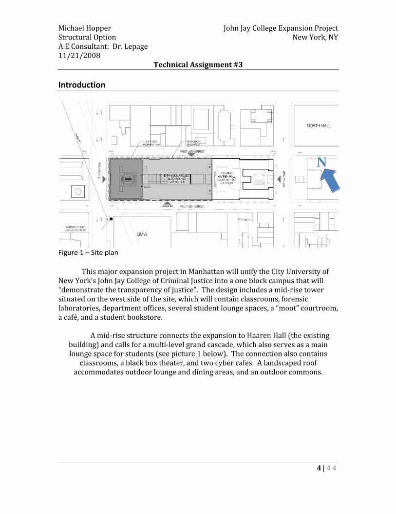
Figure 1 – Site plan
This major expansion project in Manhattan will unify the City University of New York’s John Jay College of Criminal Justice into a one block campus that will “demonstrate the transparency of justice”. The design includes a mid‐rise tower situated on the west side of the site, which will contain classrooms, forensic laboratories, department offices, several student lounge spaces, a “moot” courtroom, a café, and a student bookstore.
A mid‐rise structure connects the expansion to Haaren Hall (the existing building) and calls for a multi‐level grand cascade, which also serves as a main lounge space for students (see picture 1 below). The connection also contains
classrooms, a black box theater, and two cyber cafes. A landscaped roof accommodates outdoor lounge and dining areas, and an outdoor commons.
N

Michael Hopper John Jay College Expansion Project Structural Option New York, NY A E Consultant: Dr. Lepage 11/21/2008
Technical Assignment #3
5 | 4 4
Picture 1 – Rendering of the Grand Cascade
Amtrak tracks cross the south‐west corner of the site, which is beneath the
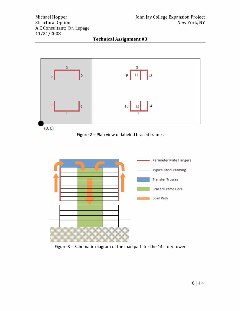
mid‐rise tower. This restriction led to a unique structural solution to transfer over the tracks. Floors 1 through 5 are transferred over the tracks using built‐up steel transfer girders and floors 6 through 14 are hanging from perimeter plate hangers supported at the penthouse level by transfer trusses that are one‐story tall (see figure 3 below). These trusses then transfer the loads to the lateral force‐resisting system, which is a steel braced frame. This braced frame wraps around a centralized service core located in the 14 story tower. A braced frame is also utilized in the service core of the 5 story cascade.
The remainder of this report investigates the existing lateral force‐resisting system. A detailed lateral analysis was performed using ETABS and forces were verified using hand calculations. Members of the braced frame were checked for strength and drift requirements. Throughout this report, braced frames will be referred to as shown below in figure 2.
Michael Hopper John Jay College Expansion Project Structural Option New York, NY A E Consultant: Dr. Lepage 11/21/2008
Technical Assignment #3
6 | 4 4
Figure 2 – Plan view of labeled braced frames
Figure 3 – Schematic diagram of the load path for the 14 story tower
Michael Hopper John Jay College Expansion Project Structural Option New York, NY A E Consultant: Dr. Lepage 11/21/2008
Technical Assignment #3
7 | 4 4
Existing Composite Steel System Floor System:
The floor system of the John Jay College Expansion Project is a composite system with the most typical bay size being 30’‐0”x 37’‐10”. 3 ½” light weight concrete and 3” metal decking typically span 12’‐2” to W14x22 or W16x26 infill beams. ¾” diameter x 5 ½” long shear studs allow composite action between the floor system and beams. Infill beams span into W‐shape girders of varying sizes or two back‐to‐back MC‐shapes. Framing of the cascade, which connects the tower to the existing building (Haaren Hall), consists of W36 girders spanning 68’‐4” with infill beams spaced typically at 11’‐4” on center. See Appendix A for typical floor framing plans. Lateral system:
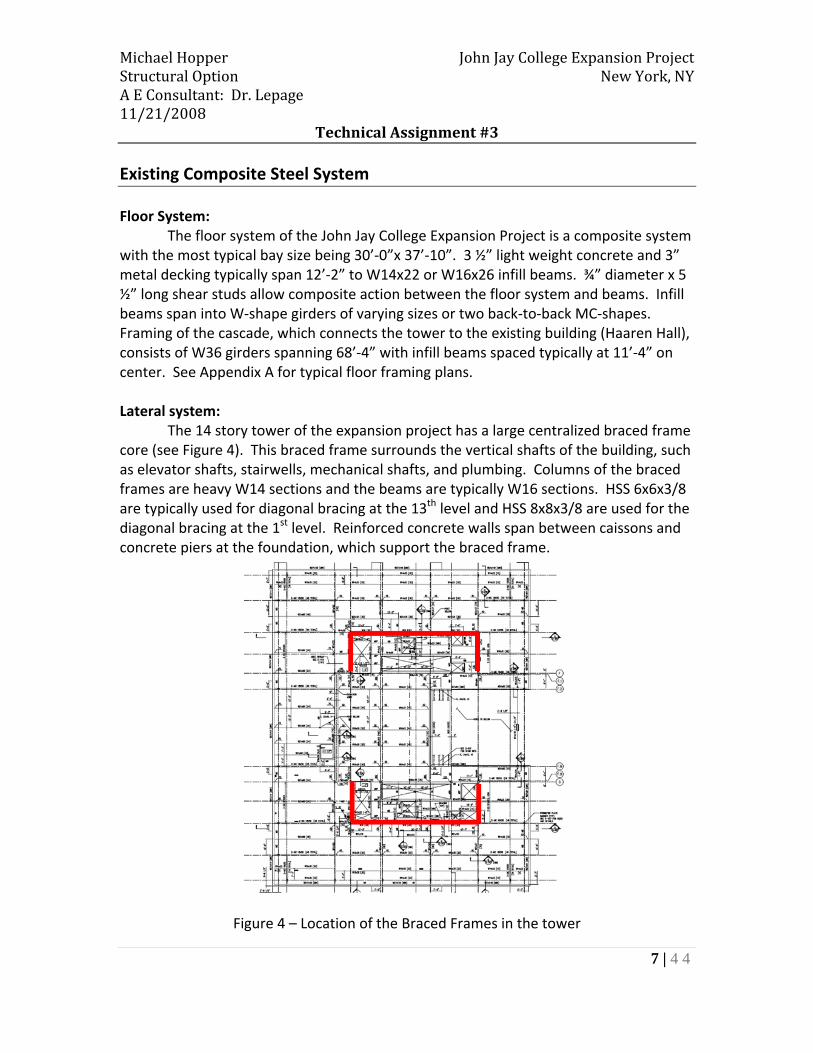
The 14 story tower of the expansion project has a large centralized braced frame core (see Figure 4). This braced frame surrounds the vertical shafts of the building, such as elevator shafts, stairwells, mechanical shafts, and plumbing. Columns of the braced frames are heavy W14 sections and the beams are typically W16 sections. HSS 6x6x3/8 are typically used for diagonal bracing at the 13th level and HSS 8x8x3/8 are used for the diagonal bracing at the 1st level. Reinforced concrete walls span between caissons and concrete piers at the foundation, which support the braced frame.
Figure 4 – Location of the Braced Frames in the tower
Michael Hopper John Jay College Expansion Project Structural Option New York, NY A E Consultant: Dr. Lepage 11/21/2008
Technical Assignment #3
8 | 4 4
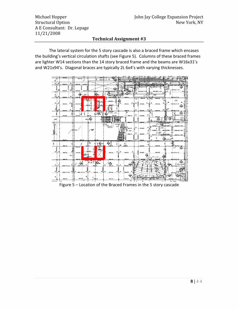
The lateral system for the 5 story cascade is also a braced frame which encases the building’s vertical circulation shafts (see Figure 5). Columns of these braced frames are lighter W14 sections than the 14 story braced frame and the beams are W16x31’s and W21x94’s. Diagonal braces are typically 2L 6x4’s with varying thicknesses.
Figure 5 – Location of the Braced Frames in the 5 story cascade

Michael Hopper John Jay College Expansion Project Structural Option New York, NY A E Consultant: Dr. Lepage 11/21/2008
Technical Assignment #3
9 | 4 4
Codes, Design Criteria, and Load Combinations Codes:
It should be noted that the original design for the John Jay College Expansion project used the Building Code of the City of New York. The designers also used ASD for sizing the members of the lateral force‐resisting system. This report will use the following codes and standards, as well as LRFD to perform spot checks: National Model Code: 2006 International Building Code Structural Standards:
ASCE 7‐05, Minimum Design Loads for Buildings and other Structures Design Codes:
Steel Construction Manual 13th edition, American Institute of Steel Construction
Deflection Criteria: Allowable Building Drift: Δ wind = H/400 Allowable Story Drift: Δ seismic = 0.015hsx Load Cases and Combinations:
The following load combinations are considered in this report and are taken from section 2.3 of ASCE 7‐05.
1.4D 1.2D + 1.6L + 0.5Lr 1.2D + 1.6Lr + (1.0L or 0.8W) 1.2D + 1.6W + 1.0L + 0.5Lr 1.2D + 1.0E + 1.0L 0.9D + 1.6W 0.9D + 1.0E
Michael Hopper John Jay College Expansion Project Structural Option New York, NY A E Consultant: Dr. Lepage 11/21/2008
Technical Assignment #3
10 | 4 4
Due to the rectangular geometry of the building, wind load combinations one and three in Figure 6‐9 of ASCE 7 ‐05 were applied. Wind load cases two and four were not analyzed and will be considered in future studies. Snow loads were also not considered in this analysis.

Michael Hopper John Jay College Expansion Project Structural Option New York, NY A E Consultant: Dr. Lepage 11/21/2008
Technical Assignment #3
11 | 4 4
Building Loads The following loads were determined in technical report one. ASCE 7 – 05 was used to determine both gravity and lateral loads. Gravity Loads: Construction Dead Loads:
Typical floor Construction: 3” Metal Decking: 20 Gage Minimum 3 psf
3 ½” Lightweight Concrete Slab (115 psf) 48 psf Allowance for Self Weight of Steel Framing 7 psf
Total CDL for Floor System Design: 51 psf Total CDL for Seismic Calculations: 58 psf
Mechanical and Mezzanine floor Construction:
3” Metal Decking: 20 Gage Minimum 3 psf 4 ½” Normal weight Concrete Slab 75 psf
Allowance for Self Weight of Steel Framing 7 psf Total CDL for Floor System Design: 78 psf Total CDL for Seismic Calculations: 85 psf
Superimposed Dead Loads:
Typical floor Construction: Fireproofing 2 psf Finishes 5 psf Partitions 20 psf Ceiling 5 psf
Mech. & Electrical Distribution 5 psf Total SDL: 37 psf

Michael Hopper John Jay College Expansion Project Structural Option New York, NY A E Consultant: Dr. Lepage 11/21/2008
Technical Assignment #3
12 | 4 4
Live Loads:
Space Load Classrooms 40 psf Offices 50 psf
Lobbies & Corridors 100 psf
Cascade 100 psf (assume
corridor/lobby/bleachers) Stairs 100 psf
Assembly areas (moot court and quad spaces)
60 psf (fixed seats) 100 psf (movable seats)
Roof 20 psf Heavy Mechanical Equipment:
Location Load
6th, 7th, & 8th Floor: Increased loads in laboratory spaces 100 psf (assumed) Penthouse Mezzanine Level 63 kips (Total load)
Penthouse Level 853 kips (Total Load)

Michael Hopper John Jay College Expansion Project Structural Option New York, NY A E Consultant: Dr. Lepage 11/21/2008
Technical Assignment #3
13 | 4 4
Lateral Loads: Wind Loads:
See figure 6 and 7 below for the wind loads which were applied at the center of pressure for each level of the John Jay College Expansion Project. For detailed calculations and the assumptions used when determining the wind forces, see appendix C. Seismic Loads: Seismic loads were determined in technical report one with a few minor changes. Forces were calculated using chapters 11 and 12 of ASCE 7 – 05. Listed below in table 1 are the seismic loads which were applied in both directions for the ETABS model at the center of mass. Please see appendix D for the assumptions used when calculating seismic loads.
Figure 7 – North‐South Wind Force diagram. Note: The first 5 levels of the N‐S direction are approximately 500 ft wide. See appendix C for calculations.
Figure 6 – East‐West Wind Force Diagram

Michael Hopper John Jay College Expansion Project Structural Option New York, NY A E Consultant: Dr. Lepage 11/21/2008
Technical Assignment #3
14 | 4 4
Table 1 – Lateral forces, story shears, and overturning moments due to seismic forces
Level Story Weight Height wxhxk Cvx Lateral Force Story Shear Moment
wx (Kips) hx (ft) Fx (kips) Vx (kips) Mx (ft‐k)
Roof 3286 236.67 5529107 0.134 139 0 32803
Penthouse 6502 206.67 9101073 0.221 228 139 4715113 2874 191.67 3631231 0.088 91 367 1744712 2822 176.67 3191293 0.077 80 458 1413411 3040 161.67 3047887 0.074 76 538 1235210 2638 146.67 2317053 0.056 58 614 85199 3040 131.67 2306064 0.056 58 672 76128 2870 116.67 1847361 0.045 46 730 5403
7 2929 101.67 1563720 0.038 39 776 3985
6 3785 86.67 1626559 0.039 41 816 3534
5 12565 66.67 3780295 0.092 95 856 63184 8483 51.17 1781485 0.043 45 951 22853 10119 31.17 1083535 0.026 27 996 8472 10932 15.58 456219 0.011 11 1023 178
Total 81866 236.67 41262883 1.000 1034 1034 162568

Michael Hopper John Jay College Expansion Project Structural Option New York, NY A E Consultant: Dr. Lepage 11/21/2008
Technical Assignment #3
15 | 4 4
ETABS Model
ETABS was used to perform a detailed lateral analysis of the John Jay College
Expansion Project. This analysis was performed by modeling the existing lateral systems, as well as treating each floor as a rigid diaphragm. Gravity members were neglected in this analysis, but were accounted for when calculating the building’s weight for seismic loads. Wind loads were applied at the center of pressure of each level and seismic loads were placed at the center of mass of each level. Five lateral load cases were investigated:
• 100 percent of the wind forces in the East‐West direction • 100 percent of the wind forces in the North‐South direction • 75 percent of the East‐West and North‐South wind forces applied simultaneously • Seismic loads in the East‐West direction • Seismic loads in the North‐South direction

Michael Hopper John Jay College Expansion Project Structural Option New York, NY A E Consultant: Dr. Lepage 11/21/2008
Technical Assignment #3
16 | 4 4
As mentioned above, all of the required combinations of lateral loads were not studied in this report. Wind load cases two and four in Figure 6‐9 of ASCE 7 – 05 will be investigated in more detail in the future.
A few important assumptions were used during the modeling procedure. The penthouse level has several cantilevered trusses which were not completely modeled. To account for the stiffness of these additional trusses at the penthouse level, members within the braced frames were modified by an area factor of 5. Trusses connecting frames 3 to 4 and 5 to 6 were modeled with no property modifiers to allow for a realistic shear transfer between frames. The differences between the existing braced frames and those modeled in ETABS can be found in appendix B.

Michael Hopper John Jay College Expansion Project Structural Option New York, NY A E Consultant: Dr. Lepage 11/21/2008
Technical Assignment #3
17 | 4 4
Lateral Force Distribution and Analysis Distribution of lateral forces to the braced frames was determined based on the
relative stiffness of each braced frame. Floor diaphragms are assumed to be infinitely rigid, and therefore distribute lateral loads to each frame based on their stiffness. Two hand calculation methods were used to calculate the center of rigidity at the 8th level using the South‐West corner of the building as the origin. From this point, direct shear and shear due to torsion about the center of rigidity were calculated and compared to story shear results provided by ETABS. The first method to calculate the center of rigidity was to directly calculate the x and y‐coordinates from the approximate stiffness of each frame. To do this, a separate ETABS model was created by removing the rigid diaphragms. A one kip load was then applied to each frame at the 8th level. Torsion was neglected to avoid any additional shear from torsion being applied to the frames. Finally, this stiffness was calculated by taking the inverse of the displacement of each frame at the 8th level. Table 2 below displays the approximate stiffness of each frame using method one.
Table 2 – Approximate frame stiffness
From this information, the center of rigidity was found to be at Xr = 81.84 ft and Yr = 100 ft. This method neglects considerations of the center of rigidities of the stories below, and therefore is fairly inaccurate due to the contributions of levels 5 and below, where the x‐coordinate of the center of rigidity significantly changes (see table 5 and figure 8). A summary of direct shear forces and shear forces generated from torsion about the center of rigidity when a North‐South wind force of 714 kips was applied at the center of pressure can be found below in table 3.
Load Displacement Stiffness(kips) (in) (kips/in)
E‐W 1 1 0.0043 233 0.282E‐W 2 1 0.0043 233 0.282N‐S 3 1 0.011682 86 0.104N‐S 4 1 0.011706 85 0.104N‐S 5 1 0.010665 94 0.114N‐S 6 1 0.010667 94 0.114
Total = 824
Approximate Frame Stiffness Calculation: Method 1
Location Direction Braced Frame Stiffness Factor
Level 8
Michael Hopper John Jay College Expansion Project Structural Option New York, NY A E Consultant: Dr. Lepage 11/21/2008
Technical Assignment #3
18 | 4 4
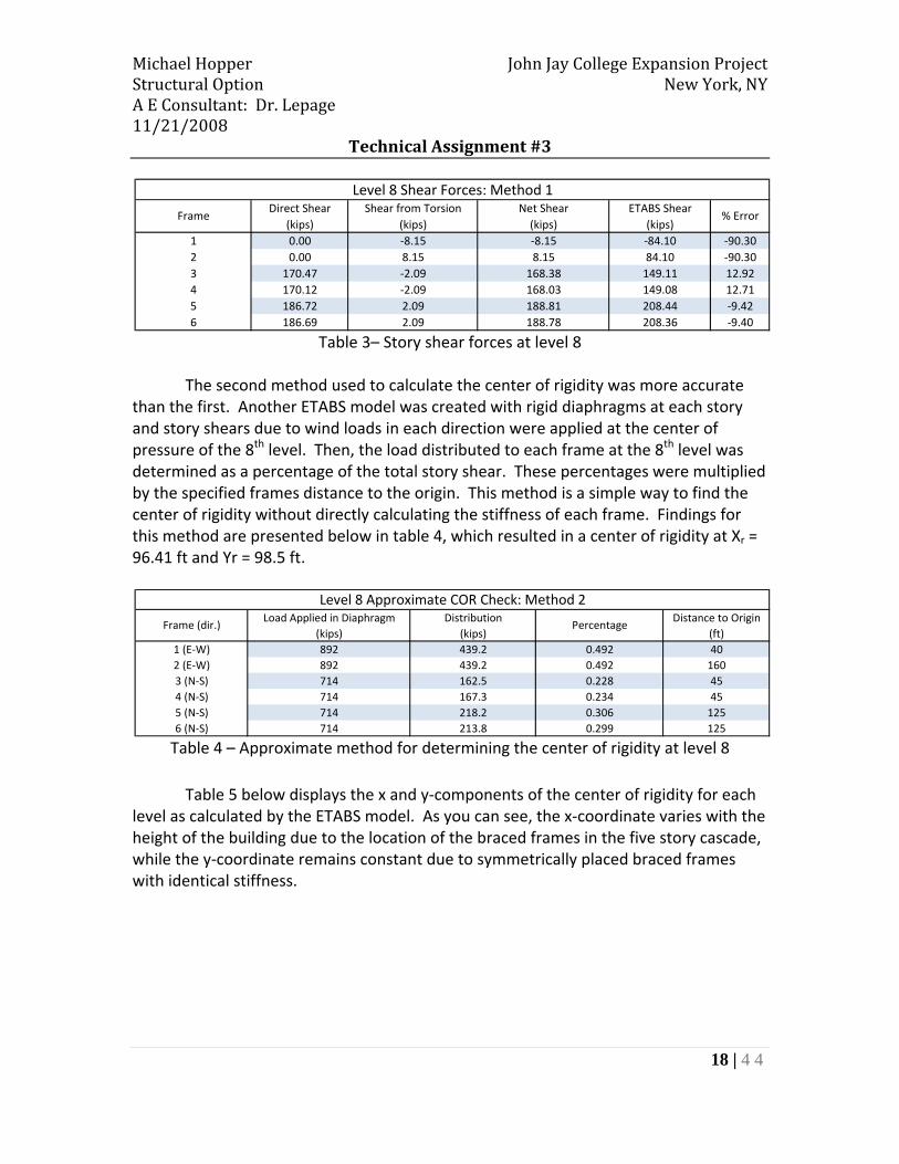
Table 3– Story shear forces at level 8
The second method used to calculate the center of rigidity was more accurate than the first. Another ETABS model was created with rigid diaphragms at each story and story shears due to wind loads in each direction were applied at the center of pressure of the 8th level. Then, the load distributed to each frame at the 8th level was determined as a percentage of the total story shear. These percentages were multiplied by the specified frames distance to the origin. This method is a simple way to find the center of rigidity without directly calculating the stiffness of each frame. Findings for this method are presented below in table 4, which resulted in a center of rigidity at Xr = 96.41 ft and Yr = 98.5 ft.
Table 4 – Approximate method for determining the center of rigidity at level 8
Table 5 below displays the x and y‐components of the center of rigidity for each level as calculated by the ETABS model. As you can see, the x‐coordinate varies with the height of the building due to the location of the braced frames in the five story cascade, while the y‐coordinate remains constant due to symmetrically placed braced frames with identical stiffness.
Direct Shear Shear from Torsion Net Shear ETABS Shear(kips) (kips) (kips) (kips)
1 0.00 ‐8.15 ‐8.15 ‐84.10 ‐90.302 0.00 8.15 8.15 84.10 ‐90.303 170.47 ‐2.09 168.38 149.11 12.924 170.12 ‐2.09 168.03 149.08 12.715 186.72 2.09 188.81 208.44 ‐9.426 186.69 2.09 188.78 208.36 ‐9.40
% ErrorFrame
Level 8 Shear Forces: Method 1
Load Applied in Diaphragm Distribution Distance to Origin(kips) (kips) (ft)
1 (E‐W) 892 439.2 0.492 402 (E‐W) 892 439.2 0.492 1603 (N‐S) 714 162.5 0.228 454 (N‐S) 714 167.3 0.234 455 (N‐S) 714 218.2 0.306 1256 (N‐S) 714 213.8 0.299 125
Frame (dir.) Percentage
Level 8 Approximate COR Check: Method 2

Michael Hopper John Jay College Expansion Project Structural Option New York, NY A E Consultant: Dr. Lepage 11/21/2008
Technical Assignment #3
19 | 4 4
Table 5 – COR locations as calculated by ETABS from the South‐West corner of the building The differences in the 14 story tower between the center of rigidity and the center of pressure, as well as the center of rigidity and the center of mass, create a significant amount of shear to be resisted by the braced frames. This is verified by the ETABS model and by the hand calculations above in method 1. When viewing the animation of the natural period about the vertical axis, the tower twists about the center of rigidity, while the lower levels remain relatively stationary.
Xr Yr(ft) (ft)
14 103 10013 103 10012 104 10011 105 10010 107 1009 108 1008 110 1007 113 1006 118 1005 129 1004 227 1003 240 1002 269 100
Level
ETABS Center of Rigidity
Figure 8– North elevation showing the location of Xr
‐ Braced Frames ‐ Location of Xr
(0, 0)

Michael Hopper John Jay College Expansion Project Structural Option New York, NY A E Consultant: Dr. Lepage 11/21/2008
Technical Assignment #3
20 | 4 4
Analysis Results The three dimensional model created in ETABS was built with the intention of obtaining more realistic results than those calculated by hand. After performing hand calculations and comparing them to the results from the detailed lateral analysis from ETABS, the discrepancies in story shear can be explained by the differences in the shear due to torsion. More accurate centers of rigidity were calculated with ETABS, by accounting for the effect shown in figure 8 caused by the braced frames in the 5‐story cascade. Story shears were determined to control in the analysis by using wind loads from wind load case 1 of figure 6‐9 in ASCE 7 ‐05. Tables 6 and 7 present story shears for each frame in the John Jay College Expansion Project. Discrepancies between total base shears and the base shear listed in the wind loading table in appendix C is due to the contribution of the out‐of‐plane frames.
Table 6 – Tower Braced Frame story shears due to wind loading
1 2 3 4 5 6Roof 0 0 0 0 0 014 63.1 63.1 83.6 83.6 17.0 17.013 153.7 153.8 60.8 60.8 61.7 58.712 214.2 213.9 76.9 76.9 96.0 96.511 273.6 273.6 92.7 92.7 125.0 125.110 329.5 329.5 111.4 111.4 155.4 155.39 390.4 390.9 128.9 128.9 182.4 182.58 446.1 446.1 149.1 149.1 208.4 280.47 501.3 501.4 168.0 168.0 233.5 233.56 559.8 559.8 188.2 188.2 258.4 258.45 606.1 606.1 272.3 272.3 217.4 217.44 407.6 408.6 348.1 348.1 137.4 137.43 386.5 386.5 270.0 270.0 235.4 235.42 334.5 344.5 295.9 295.8 230.7 230.7
BASE 375.1 375.1 343.8 343.8 253.7 253.6
Tower Braced Frames: Story shear
(kips) (kips)LevelEast‐West Frames North‐South Frames
Michael Hopper John Jay College Expansion Project Structural Option New York, NY A E Consultant: Dr. Lepage 11/21/2008
Technical Assignment #3
21 | 4 4
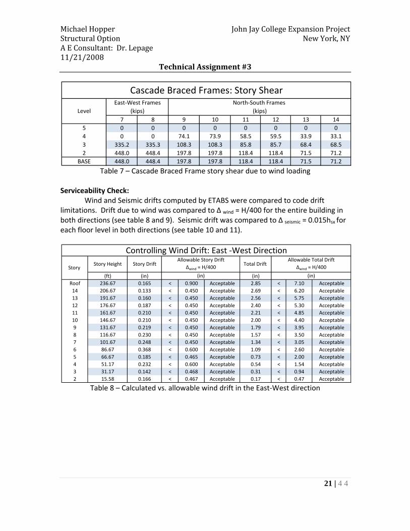
Table 7 – Cascade Braced Frame story shear due to wind loading
Serviceability Check: Wind and Seismic drifts computed by ETABS were compared to code drift limitations. Drift due to wind was compared to Δ wind = H/400 for the entire building in both directions (see table 8 and 9). Seismic drift was compared to Δ seismic = 0.015hsx for each floor level in both directions (see table 10 and 11).
Table 8 – Calculated vs. allowable wind drift in the East‐West direction
7 8 9 10 11 12 13 145 0 0 0 0 0 0 0 04 0 0 74.1 73.9 58.5 59.5 33.9 33.13 335.2 335.3 108.3 108.3 85.8 85.7 68.4 68.52 448.0 448.4 197.8 197.8 118.4 118.4 71.5 71.2
BASE 448.0 448.4 197.8 197.8 118.4 118.4 71.5 71.2
East‐West Frames North‐South Frames (kips) (kips)
Cascade Braced Frames: Story Shear
Level
(ft) (in) (in)Roof 236.67 0.165 < 0.900 Acceptable 2.85 < 7.10 Acceptable14 206.67 0.133 < 0.450 Acceptable 2.69 < 6.20 Acceptable13 191.67 0.160 < 0.450 Acceptable 2.56 < 5.75 Acceptable12 176.67 0.187 < 0.450 Acceptable 2.40 < 5.30 Acceptable11 161.67 0.210 < 0.450 Acceptable 2.21 < 4.85 Acceptable10 146.67 0.210 < 0.450 Acceptable 2.00 < 4.40 Acceptable9 131.67 0.219 < 0.450 Acceptable 1.79 < 3.95 Acceptable8 116.67 0.230 < 0.450 Acceptable 1.57 < 3.50 Acceptable7 101.67 0.248 < 0.450 Acceptable 1.34 < 3.05 Acceptable6 86.67 0.368 < 0.600 Acceptable 1.09 < 2.60 Acceptable5 66.67 0.185 < 0.465 Acceptable 0.73 < 2.00 Acceptable4 51.17 0.232 < 0.600 Acceptable 0.54 < 1.54 Acceptable3 31.17 0.142 < 0.468 Acceptable 0.31 < 0.94 Acceptable2 15.58 0.166 < 0.467 Acceptable 0.17 < 0.47 Acceptable
Allowable Story DriftΔwind = H/400
(in)
Allowable Total DriftΔwind = H/400
(in)
Controlling Wind Drift: East ‐West Direction
Story Story Height Story Drift Total Drift

Michael Hopper John Jay College Expansion Project Structural Option New York, NY A E Consultant: Dr. Lepage 11/21/2008
Technical Assignment #3
22 | 4 4
Table 9 ‐ Calculated vs. allowable wind drift in the North‐South direction
Table 10 – Calculated vs. allowable seismic drift in the East‐West direction
(ft) (in) (in)Roof 236.67 0.153 < 0.900 Acceptable 4.85 < 7.10 Acceptable14 206.67 0.206 < 0.450 Acceptable 4.70 < 6.20 Acceptable13 191.67 0.245 < 0.450 Acceptable 4.49 < 5.75 Acceptable12 176.67 0.306 < 0.450 Acceptable 4.25 < 5.30 Acceptable11 161.67 0.340 < 0.450 Acceptable 3.94 < 4.85 Acceptable10 146.67 0.377 < 0.450 Acceptable 3.60 < 4.40 Acceptable9 131.67 0.396 < 0.450 Acceptable 3.22 < 3.95 Acceptable8 116.67 0.408 < 0.450 Acceptable 2.83 < 3.50 Acceptable7 101.67 0.413 < 0.450 Acceptable 2.42 < 3.05 Acceptable6 86.67 1.292 > 0.600 Unacceptable 2.01 < 2.60 Acceptable5 66.67 0.156 < 0.465 Acceptable 0.72 < 2.00 Acceptable4 51.17 0.299 < 0.600 Acceptable 0.56 < 1.54 Acceptable3 31.17 0.017 < 0.468 Acceptable 0.26 < 0.94 Acceptable2 15.58 0.276 < 0.467 Acceptable 0.28 < 0.47 Acceptable
Controlling Wind Drift: North ‐South DirectionAllowable Total Drift
Δwind = H/400 Δwind = H/400
(in) (in)
Story Story Height Story Drift
Allowable Story DriftTotal Drift
(ft) (in) (in)Roof 236.67 0.154 < 0.450 Acceptable 2.29 < 3.55 Acceptable14 206.67 0.137 < 0.225 Acceptable 2.14 < 3.10 Acceptable13 191.67 0.158 < 0.225 Acceptable 2.00 < 2.88 Acceptable12 176.67 0.176 < 0.225 Acceptable 1.84 < 2.65 Acceptable11 161.67 0.190 < 0.225 Acceptable 1.67 < 2.43 Acceptable10 146.67 0.181 < 0.225 Acceptable 1.48 < 2.20 Acceptable9 131.67 0.180 < 0.225 Acceptable 1.30 < 1.98 Acceptable8 116.67 0.180 < 0.225 Acceptable 1.12 < 1.75 Acceptable7 101.67 0.186 < 0.225 Acceptable 0.94 < 1.53 Acceptable6 86.67 0.262 < 0.300 Acceptable 0.75 < 1.30 Acceptable5 66.67 0.131 < 0.233 Acceptable 0.49 < 1.00 Acceptable4 51.17 0.160 < 0.300 Acceptable 0.36 < 0.77 Acceptable3 31.17 0.095 < 0.234 Acceptable 0.20 < 0.47 Acceptable2 15.58 0.102 < 0.234 Acceptable 0.10 < 0.23 Acceptable
Seismic Drift: East ‐West Direction
Story Story Height Story Drift
Allowable Story DriftTotal Drift
Allowable Total DriftΔseismic = 0.015hsx Δseismic = 0.015hsx
(in) (in)

Michael Hopper John Jay College Expansion Project Structural Option New York, NY A E Consultant: Dr. Lepage 11/21/2008
Technical Assignment #3
23 | 4 4
Table 11 – Calculated vs. allowable seismic drift in the North‐South direction
As displayed above in the tables, the total drift and story drift in the East‐West direction is acceptable for both wind and seismic loads. However, several calculated story drifts and the total building drift in the North‐South direction were unacceptable for seismic loading. Although the building displaced more under wind loading, strict drift limitations for an Occupancy Category of III caused seismic loads to govern the serviceability design of the North‐South Direction. These unacceptable drift calculations were not expected, since wind forces in New York City usually control the lateral force‐resisting system design. This major discrepancy was justified by looking into the original design criteria of the John Jay College Expansion project and the Building Code of the City of New York. It was found that lateral drifts for seismic loads are limited to H/260 for the total building height and story height. By comparing the drift calculations above for seismic forces to the limit of H/260, it was determined that the total building drift and each story drift was acceptable and that wind forces governed the design for both strength and serviceability.
(ft) (in) (in)Roof 236.67 0.165 < 0.450 Acceptable 4.55 > 3.55 Unacceptable14 206.67 0.231 > 0.225 Unacceptable 4.39 > 3.10 Unacceptable13 191.67 0.269 > 0.225 Unacceptable 4.16 > 2.88 Unacceptable12 176.67 0.335 > 0.225 Unacceptable 3.89 > 2.65 Unacceptable11 161.67 0.363 > 0.225 Unacceptable 3.55 > 2.43 Unacceptable10 146.67 0.390 > 0.225 Unacceptable 3.19 > 2.20 Unacceptable9 131.67 0.399 > 0.225 Unacceptable 2.80 > 1.98 Unacceptable8 116.67 0.397 > 0.225 Unacceptable 2.40 > 1.75 Unacceptable7 101.67 0.389 > 0.225 Unacceptable 2.00 > 1.53 Unacceptable6 86.67 1.151 > 0.300 Unacceptable 1.62 > 1.30 Unacceptable5 66.67 0.115 < 0.233 Acceptable 0.47 < 1.00 Acceptable4 51.17 0.191 < 0.300 Acceptable 0.35 < 0.77 Acceptable3 31.17 0.018 < 0.234 Acceptable 0.16 < 0.47 Acceptable2 15.58 0.176 < 0.234 Acceptable 0.18 < 0.23 Acceptable
(in) (in)
Seismic Drift: North ‐South Direction
Story Story Height Story Drift
Allowable Story DriftTotal Drift
Allowable Total DriftΔseismic = 0.015hsx Δseismic = 0.015hsx

Michael Hopper John Jay College Expansion Project Structural Option New York, NY A E Consultant: Dr. Lepage 11/21/2008
Technical Assignment #3
24 | 4 4
Overturning Analysis and Foundation Impact An overturning analysis was performed for the 14 story braced frame core. It was expected that overturning would not be an issue in the North‐South direction due to the coupling action through the transfer trusses at the penthouse level between braced frames 3 and 4, as well as braced frames 5 and 6. This prediction was verified in table 12 below when the uplift forces at edge columns due to overturning moments were compared to the dead load in the same edge columns. After analyzing the East‐West direction, it was also determined that overturning will not be an issue.
Since the 14 story braced frame carries additional gravity loads from the hanging floors, it was very unlikely that overturning would be an issue. This theory is verified through the calculations in table 12 and therefore the foundation system does not need to be designed to resist overturning forces.
Table 12 – Story forces and overturning analysis for the 14 story braced frame core
1 2 3 4 5 6Roof 63.1 63.1 83.6 83.6 17.0 17.014 90.6 90.6 ‐22.7 ‐22.7 44.7 41.713 60.4 60.1 16.1 16.1 34.3 37.712 59.4 59.7 15.8 15.8 29.0 28.611 55.9 55.9 18.7 18.7 30.4 30.210 60.8 61.4 17.5 17.5 27.0 27.29 55.7 55.2 20.3 20.3 26.1 25.98 55.3 55.3 18.9 18.9 25.1 25.17 58.4 58.4 20.2 20.2 24.9 24.86 46.3 46.3 84.1 84.1 ‐41.0 ‐41.05 ‐198.5 ‐197.6 75.8 75.8 ‐80.0 ‐80.04 ‐21.1 ‐22.1 ‐78.1 ‐78.1 98.0 98.03 ‐52.1 ‐42.0 25.8 25.8 ‐4.7 ‐4.62 40.6 30.6 47.9 47.9 22.9 22.9
BASE 375.1 375.1 343.8 343.8 253.7 253.6
1 2OverturningMoment (ft‐k)
Base Dimension (ft) 80 80Force at
Edge Column (k)Edge Column DL (k) 1083 1083
Overturning: OK OK
East‐West Frame North‐South Frames
Tower Braced Frames: Overturning Check
86720 78075
3 & 4 Coupled 5 & 6 Coupled
120
723
1083OK
120
651
1083OK
1027 1029
82154 82325
Tower Braced Frames: Story forces
LevelEast‐West Frames North‐South Frames
(kips) (kips)

Michael Hopper John Jay College Expansion Project Structural Option New York, NY A E Consultant: Dr. Lepage 11/21/2008
Technical Assignment #3
25 | 4 4
At the 5th level of the John Jay College Expansion Project the braced frames in the cascade are discontinued. Therefore, there is a sudden change in stiffness of the overall lateral force‐resisting systems at the same level. This is apparent in the story force data above in table 12 where there is a large shear reversal in the 5th level of the East‐West frames.

Michael Hopper John Jay College Expansion Project Structural Option New York, NY A E Consultant: Dr. Lepage 11/21/2008
Technical Assignment #3
26 | 4 4
Lateral Member Spot Checks Member spot checks were performed for braced frame 1. Figure 9 displays the members which were checked for strength by attaining forces from the ETABS model. Gravity loads were not accounted for in the ETABS model, so a gravity load takedown was performed for each column in the lateral system (a gravity load takedown is available upon request). These gravity loads included the loads transferred from the perimeter plate hangers to the braced frame core.
Figure 9 – Analyzed members of the lateral force‐resisting system

Michael Hopper John Jay College Expansion Project Structural Option New York, NY A E Consultant: Dr. Lepage 11/21/2008
Technical Assignment #3
27 | 4 4
Bracing Members: Below are the calculations for each bracing member analyzed. Design of braced frame 1 was controlled by wind in the East‐West direction, and therefore the controlling load combination was 1.6W. Brace at Level 2:
Brace at Level 8:
Location P M(Member Size) (k) (k‐ft)Level 2 Brace Service Wind East‐West 103.03(HSS 8 x 8 x3/8) Factored 1.6W 165
LoadCase
Location P M(Member Size) (k) (k‐ft)Level 8 Brace Service Wind East‐West 114.2(HSS 7 x 7 x3/8) Factored 1.6W 183
LoadCase

Michael Hopper John Jay College Expansion Project Structural Option New York, NY A E Consultant: Dr. Lepage 11/21/2008
Technical Assignment #3
28 | 4 4
Brace at Level 12:
All of these members were determined to be more than adequate for strength requirements. Since none of these members are more than 90% stressed, it is believed they were sized based on drift requirements rather than strength.
Location P M(Member Size) (k) (k‐ft)Level 12 Brace Service Wind East‐West 60.13(HSS 6 x 6 x3/8) Factored 1.6W 96
LoadCase

Michael Hopper John Jay College Expansion Project Structural Option New York, NY A E Consultant: Dr. Lepage 11/21/2008
Technical Assignment #3
29 | 4 4
Column Members: The following calculations are for the column members analyzed in this report. Since these columns are end columns for braced frames 1 and 4, wind forces from the East‐West and North‐South directions were considered when determining the controlling load combination. Column at Level 2:
Location P M(Member Size) (k) (k‐ft)
Wind East‐West 564.83 27.5Wind North‐South 679.5 28.325
DL 999 0Level 2 column LL 884 0(W14 x 426) 1.4D 1399 0
1.2D + 1.6L 2612 01.2D + 1.6W +1.0L 3169 45
.9D + 1.6W 1986 45
Service
Factored
LoadCase

Michael Hopper John Jay College Expansion Project Structural Option New York, NY A E Consultant: Dr. Lepage 11/21/2008
Technical Assignment #3
30 | 4 4
Column at Level 12:
Both of these columns were determined to be adequate for the loads determined through a detailed lateral analysis. Design forces for the column at level 12 were controlled by 1.2D + 1.6L. This is justified by the large gravity loads at the 12th level, which is a unique situation for this building due to the braced frame core supporting gravity loads from perimeter plate hangers. Design forces for the column at the 2nd level were controlled by 1.2D + 1.6W +1.0L, which is the expected load combination for columns in a braced frame. When analyzed for strength, the W14x500 at level 12 was determined to be 31.5 percent stressed, and therefore was sized to meet drift requirements. The W14x426 at the 2nd level was determined to be 86 percent stressed, and it is also believed that it is designed for drift requirements.
Location P M(Member Size) (k) (k‐ft)
Wind East‐West 13.67 17.024Wind North‐South 133.8 15.2
DL 718 0Level 12 Column LL 616 0(W14 x 500) 1.4D 1005 0
1.2D + 1.6L 1848 01.2D + 1.6W +1.0L 1692 24
.9D + 1.6W 860 24
LoadCase
Service
Factored

Michael Hopper John Jay College Expansion Project Structural Option New York, NY A E Consultant: Dr. Lepage 11/21/2008
Technical Assignment #3
31 | 4 4
Conclusions In the third technical report of the John Jay College Expansion project a detailed lateral analysis was performed and lateral members were analyzed for strength requirements. An ETABS model was created to ensure a realistic distribution of story forces to the lateral force‐resistant systems was achieved. This was accomplished by modeling the existing braced frames and treating the floor systems as infinitely rigid diaphragms. Lateral forces were distributed by the relative stiffness of each frame with respect to the stiffness of the other frames. Several combinations of loads were applied to the ETABS model to find the worst case for strength and serviceability requirements. Due to the rectangular geometry of the building, wind forces applied separately in the East‐West and North‐South directions controlled the overall drift of the building. However, when using ASCE 7‐05, strict drift limitations for seismic loading led to seismic drift controlling the design for the North‐South direction. This was an unexpected result, as the drift in the North‐South was unacceptable for the majority of the levels with the existing braced frames. This discrepancy was clarified when looking into the original design criteria, which used H/260 for seismic drift limitations. Since the lateral force‐resisting systems for the John Jay College Expansion Project are braced frames, the only forces present in the lateral braces are wind forces. Therefore, the braces were controlled for strength requirements by the load combination 1.6W. After analyzing the existing braces, it was determined that they were sized for drift requirements. Two columns were also checked for their controlling load combinations and strength. At the 12th level, a corner column of braced frame 1 and 4 was found to be controlled by 1.2D + 1.6L. This combination is usually unlikely to control for a member with lateral loads present, but the column supports approximately twice the gravity load from the 6th to 14th levels due to the transfer of the perimeter plate hanger loads at the penthouse level. This same column was also analyzed at the 2nd level, but the column had a substantial amount of weak axis bending due to wind forces and was controlled by 1.2D + 1.6W + 1.0L. Both of the columns analyzed in this report were determined to be controlled by drift rather than strength. From this report, it can be concluded that the existing braced frames are more than adequate for both strength and drift requirements for the Building Code of the City of New York. When using ASCE 7‐05, seismic drift is an issue in the North‐South direction. This issue, along with a more advanced torsion analysis will be further investigated throughout the rest of the year.

Michael Hopper John Jay College Expansion Project Structural Option New York, NY A E Consultant: Dr. Lepage 11/21/2008
Technical Assignment #3
32 | 4 4
Appendix A – Typical Framing Plans
Typical Tower Framing Plan

Michael Hopper John Jay College Expansion Project Structural Option New York, NY A E Consultant: Dr. Lepage 11/21/2008
Technical Assignment #3
33 | 4 4
Typical Cascade Area Framing Plan

Michael Hopper John Jay College Expansion Project Structural Option New York, NY A E Consultant: Dr. Lepage 11/21/2008
Technical Assignment #3
34 | 4 4
Appendix B – Braced Frames
Actual Braced Frames 1 and 2
Michael Hopper John Jay College Expansion Project Structural Option New York, NY A E Consultant: Dr. Lepage 11/21/2008
Technical Assignment #3
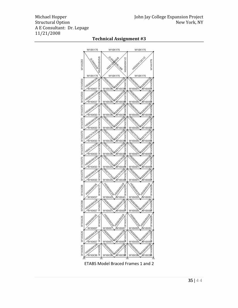
35 | 4 4
ETABS Model Braced Frames 1 and 2
Michael Hopper John Jay College Expansion Project Structural Option New York, NY A E Consultant: Dr. Lepage 11/21/2008
Technical Assignment #3
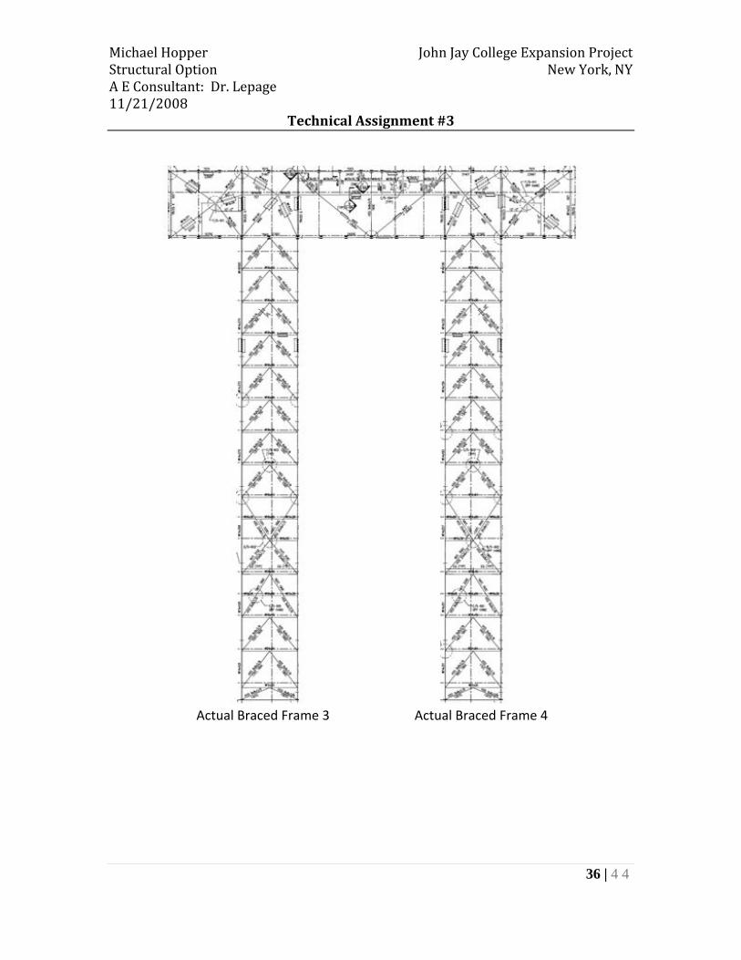
36 | 4 4
Actual Braced Frame 3 Actual Braced Frame 4

Michael Hopper John Jay College Expansion Project Structural Option New York, NY A E Consultant: Dr. Lepage 11/21/2008
Technical Assignment #3
37 | 4 4
ETABS Model Braced Frame 3 ETABS Model Braced Frame 4

Michael Hopper John Jay College Expansion Project Structural Option New York, NY A E Consultant: Dr. Lepage 11/21/2008
Technical Assignment #3
38 | 4 4
Actual Braced Frame 5 Actual Braced Frame 6

Michael Hopper John Jay College Expansion Project Structural Option New York, NY A E Consultant: Dr. Lepage 11/21/2008
Technical Assignment #3
39 | 4 4
ETABS Model Braced Frame 5 ETABS Model Braced Frame 6

Michael Hopper John Jay College Expansion Project Structural Option New York, NY A E Consultant: Dr. Lepage 11/21/2008
Technical Assignment #3
40 | 4 4
ETABS Model Braced Frame 7 and 8
ETABS Model Braced Frame 9 ETABS Model Braced Frame 10
Michael Hopper John Jay College Expansion Project Structural Option New York, NY A E Consultant: Dr. Lepage 11/21/2008
Technical Assignment #3
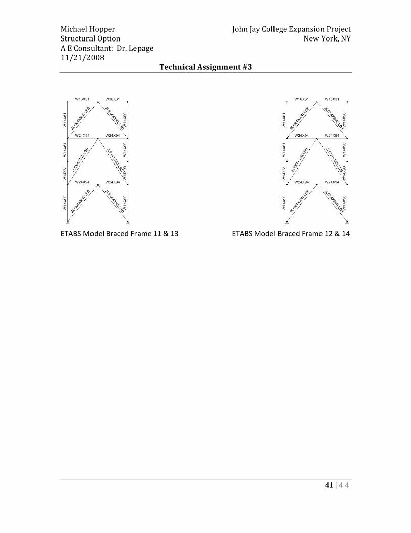
41 | 4 4
ETABS Model Braced Frame 11 & 13 ETABS Model Braced Frame 12 & 14

Michael Hopper John Jay College Expansion Project Structural Option New York, NY A E Consultant: Dr. Lepage 11/21/2008
Technical Assignment #3
42 | 4 4
Appendix C – Wind Load Calculations
Gust Effect FactorsN‐S E‐W
B 163.33 200.67
L 200.67 163.33
h 239.5 239.5n1 0.42 0.42
Structure: FLEXIBLE FLEXIBLEgR 3.976 3.976
z 143.7 143.7Iz 0.235 0.235
Lz 520 520
Q 0.807 0.799Vz 104.88 104.88
N1 2.070 2.070
Rn 0.087 0.087
Rh 0.202 0.202
n= 4.386 4.386RB 0.279 0.235
n= 2.991 3.675RL 0.078 0.095
n= 12.303 10.014R 0.236 0.218Gf 0.847 0.839
Cp Value N‐S E‐W
Windward wall 0.8 0.8Leeward Wall ‐0.454 ‐0.5Side Wall ‐0.7 ‐0.7
V= 110 mphKd= 0.85
Kd= 1.15
Kd= 1
Exposure: B
Michael Hopper John Jay College Expansion Project Structural Option New York, NY A E Consultant: Dr. Lepage 11/21/2008
Technical Assignment #3
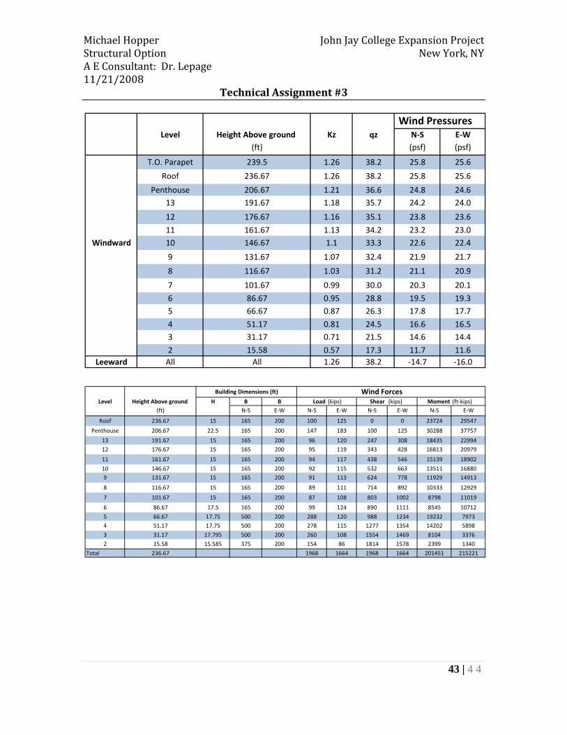
43 | 4 4
Wind PressuresLevel Height Above ground Kz qz N‐S E‐W
(ft) (psf) (psf)
T.O. Parapet 239.5 1.26 38.2 25.8 25.6
Roof 236.67 1.26 38.2 25.8 25.6
Penthouse 206.67 1.21 36.6 24.8 24.613 191.67 1.18 35.7 24.2 24.0
12 176.67 1.16 35.1 23.8 23.6
11 161.67 1.13 34.2 23.2 23.0Windward 10 146.67 1.1 33.3 22.6 22.4
9 131.67 1.07 32.4 21.9 21.7
8 116.67 1.03 31.2 21.1 20.9
7 101.67 0.99 30.0 20.3 20.1
6 86.67 0.95 28.8 19.5 19.35 66.67 0.87 26.3 17.8 17.7
4 51.17 0.81 24.5 16.6 16.53 31.17 0.71 21.5 14.6 14.4
2 15.58 0.57 17.3 11.7 11.6Leeward All All 1.26 38.2 ‐14.7 ‐16.0
Wind ForcesLevel Height Above ground H B B Load (kips) Shear (kips) Moment (ft‐kips)
(ft) N‐S E‐W N‐S E‐W N‐S E‐W N‐S E‐W
Roof 236.67 15 165 200 100 125 0 0 23724 29547
Penthouse 206.67 22.5 165 200 147 183 100 125 30288 37757
13 191.67 15 165 200 96 120 247 308 18435 2299412 176.67 15 165 200 95 119 343 428 16813 20979
11 161.67 15 165 200 94 117 438 546 15139 18902
10 146.67 15 165 200 92 115 532 663 13511 168809 131.67 15 165 200 91 113 624 778 11929 14913
8 116.67 15 165 200 89 111 714 892 10333 12929
7 101.67 15 165 200 87 108 803 1002 8798 11019
6 86.67 17.5 165 200 99 124 890 1111 8545 10712
5 66.67 17.75 500 200 288 120 988 1234 19232 79734 51.17 17.75 500 200 278 115 1277 1354 14202 5898
3 31.17 17.795 500 200 260 108 1554 1469 8104 33762 15.58 15.585 375 200 154 86 1814 1578 2399 1340
Total 236.67 1968 1664 1968 1664 201451 215221
Building Dimensions (ft)

Michael Hopper John Jay College Expansion Project Structural Option New York, NY A E Consultant: Dr. Lepage 11/21/2008
Technical Assignment #3
44 | 4 4
Appendix D – Seismic Load Calculations
Ss= 0.35 %g
S1= 0.06 %g
Occupancy Category= IIISite Class= C (Assumed)
Fa= 1.2
Fv= 1.7
Sms= 0.42
Sm1= 0.102
SDS= 0.28
SD1= 0.068
Ta= 1.218
0.8Ts= 0.194 < TaSDC= B Table 11.6‐1SDC= B Table 11.6‐2SDC= B Can use Equivalent Lateral Force ProcedureTs= 0.243
R= 3.25 Ordinary steel concentrically braced framesI= 1.25 Occupancy Category III
Ta= 1.218
Cu= 1.7
TL= 6 seconds
Cs min= 0.013 <‐‐‐ Governs
Cs max= 0.108
k= 1.36W= 81866 KipsV= 1034 Kips