january 2014 · and problems i had to face to create the guna yala indian image. the guna yalas are...
TRANSCRIPT

www.augiworld.com US $8.00
Advancing• Your Skills• Your Knowledge• Your Power
Also in this issue:• Integrated CAM with HSM
Express
• The Creative Process in 3ds Max
• The Potential for Advancement in AEC
Diamond Sponsor
January 2014
AUGIWorldT h e O f f i c i a l P u b l i c a t i o n o f A u t o d e s k U s e r G r o u p I n t e r n a t i o n a l

© Copyright 2013 Hewlett-Packard Development Company, L.P. The information contained herein is subject to change without notice. * Select configurations of the ZBook 14 qualify as an UltrabookTM
Intel, the Intel Logo, Intel Inside, Intel Core, Core Inside, and Ultrabook are trademarks of Intel Corporation in the U.S. and/or other countries.
Create. Collaborate.Innovate. On-site.Create anywhere with HP ZBook 14, the world’s first workstation Ultrabook™.* We packed the extraordinary innovation, power, and reliability of a Z Workstation into a remarkably compact design. Powered by the Intel® Core™ i7 processor, you get outstanding performance even with the most demanding applications and intensive projects, all in an unprecedented package. Working without limits no matter where you are, it matters. hp.com/go/zbook14
Make it matter.
HP recommends Windows.

AUGIWorld JAN
UA
RY
2014
contentsproduct focus
24
34
6 3ds Max 2014: The Creative Process
12 Revit Structure 2014: Creating Advanced Families in Revit
16 AutoCAD: Cleaning Up AutoCAD Drawings
24 AutoCAD Architecture 2014: Working with Point Clouds
28 Revit Architecture: The Potential for Advancement in AEC
31 Navisworks Manage 2013: Measuring Up
34 AutoCAD Civil 3D 2014: Hitting All the Keys on the Piano
36 Inventor HSM: Integrated CAM with HSM Express
January 2014 www.augi.com 3
columns4 Editor’s Note
42 Inside Track
6
28
Cover image: New Zealand Parliament buildings and statue of Richard John Seddon. Photo Copyright © 2013 – Robin Capper. Reuse of full or partial copyright image, in any form, without prior written permission is strictly prohibited. Visit Robin’s blog at http://rcd.typepad.com/ .

Editor’s NoteJA
NU
AR
Y 2
014
4 www.augi.com January 2014
➲
www.augiworld.com
EditorsEditor-in-ChiefDavid Harrington - [email protected]
Copy EditorMarilyn Law - [email protected]
Layout EditorDebby Gwaltney - [email protected]
Content Managers 3ds Max - Brian ChapmanAutoCAD - Curt MorenoAutoCAD Architecture - Melinda HeavrinAutoCAD Civil 3D - Christopher FugittAutoCAD MEP - William CampbellColumn: Inside Track - Lee AmbrosiusInventor - John EvansNavisworks - Michael SmithProduct Review - Lonnie CumptonRevit Architecture - Jay ZallanRevit MEP - Todd ShackelfordRevit Structure - Phil Russo
Advertising / Reprint SalesKate Morrical - [email protected]
AUGI Management President David Harrington
Vice President R. Robert Bell
Executive DirectorKevin Merritt
TreasurerDesirée Mackey
SecretaryMelanie Perry
Board of DirectorsR. Robert BellShaun BryantTommy HolderDesirée MackeyKate MorricalMelanie PerryMichael SmithWalt SparlingScott Wilcox
Publication InformationAUGIWorld magazine is a benefit of specific AUGI membership plans. Direct magazine subscriptions are not available. Please visit http://www.augi.com/account/register to join or upgrade your membership to receive AUGIWorld magazine in print. To manage your AUGI membership and address, please visit http://www.augi.com/account . For all other magazine inquires please contact [email protected]
Published by: AUGIWorld is published by Autodesk User Group Inter-national, Inc. AUGI makes no warranty for the use of its products and assumes no responsibility for any errors which may appear in this publication nor does it make a commitment to update the information contained herein. AUGIWorld is Copyright ©2012 AUGI. No informa-tion in this magazine may be reproduced without expressed written permission from AUGI.
All registered trademarks and trademarks included in this magazine are held by their respective companies. Every attempt was made to include all trademarks and regis-tered trademarks where indicated by their companies.
AUGIWorld (San Francisco, Calif.)ISSN 2163-7547
Hello, AUGIWorld Reader!
Welcome to the first issue of 2014! WOOHOO! We have a wonderful year planned. This year you will begin to see non-product subject matter from columnists along with our traditional Autodesk software articles. As
always, each month we have a general theme to try to focus on our content and this month is no different. For January 2014 I asked our authors to consider sharing some very advanced ideas and insight.
But before we roll into that I would like to thank Robin Capper, this month’s cover pho-tographer. Robin captured some really interested shots on a recent visit to New Zealand and shared that with us. As mentioned before, if you have neat and interesting photos to grace our cover, just contact me and perhaps you too can be “here.”
This month we start out visual with an article by Ruben Dario Karamañites Arango, who shares the creative process he uses for his work with 3ds Max. Then we have Scott Melching showing off his “metal” in creating advanced families in Revit Structure.
Next we have Walt Sparling doing a little early spring cleaning of drawing files when us-ing AutoCAD. And partnered in the AutoCAD space is Michael Beall, who brings how to edit Properties content quickly. We follow that with Melinda Heavrin, who shares what she has learned about using Point Clouds in AutoCAD Architecture.
Moving into Revit Architecture, Jennifer Storey tackles the potential for advancement in the AEC industry. And playing up the theme is Mark Hunter, who shows how to measure up when using Navisworks Manage. And then Christopher Fugitt bangs out a chorus when hitting the keyboard to find solutions for using AutoCAD Civil 3D.
Wrapping up the month we have John Evans who gets integrated CAD with HSM Express (whatever that is ) and then Lee Ambrosius with the month’s look at new products and services hot out of development in our “Inside Track” column.
There you have it! The first of many issues of AUGIWorld this year. And for those AUGI Professional Members who get AW delivered in print, thank you for supporting the organization such that we can provide you a hard copy of the magazine. See you next month!
Take care,
David HarringtonAUGIWorld Editor-in-Chief
AUGIWorld
Autodesk, AutoCAD, Autodesk Architectural Desktop, Autodesk Revit, Autodesk Building Systems, Autodesk Civil Design, Autodesk In-ventor and DWF are either registered trademarks or trademarks of Autodesk, Inc. in the U.S.A. and/or in certain other countries. All other brand names, product names, or trademarks belong to their respective holders.

BIM LibraryARCAT has the most comprehensive collecti on of BIM objects you will fi nd, available free of charge and without registrati on.
The ARCAT BIM Library is also accessible in the ARCAT app, with editi ng capabiliti es in the AutoCAD 360 app.
arcat.com facebook
you will fi nd, available free of charge and without registrati on.
The ARCAT BIM Library is also accessible in the ARCAT app,

6 www.augi.com January 2014
3ds Max 2011P
RO
DU
CT
FO
CU
S by: Ruben Dario Karamañites Arango
INTRoDUCTIoN
Why is Autodesk 3ds Max® one of the greatest programs on the market? Be-cause the tools blend so well that art-ists and other professionals can work
with it efficiently, minimizing time and effort.
In this article we will enter a realm of technical skills, tools, pitfalls, and problems I had to face to create The Guna Yala Indian image.
The Guna Yalas are native Indians of Panama and cultural icons who shape Panama’s identity. Living on islands such as San Blas among other regions and reserves, the Guna Yala people are the most pictorial and colorful of them all.
➲
The Creative Process
PHoTo SESSIoNS
First of all, I want to thank photographers Javier Conte (his web-site is www.contefotografia.com) and Rita Willaert (you can find her on Flickr http://www.flickr.com/photos/rietje/) for their per-sonal time and effort in helping to make this project possible.
In the beginning of the project I called Javier Conte and told him about the idea of generating a 3d still image based on the Guna Yalas; he was interested so we coordinated the photo sessions.
At first, we spent some time searching for someone to model. I remember looking for at least a month, but in the last week Javier remembered a friend that lived near him who agreed to help, so we started the photo shoot.
We began the sessions taking photos of the woman’s front view, side, back, close ups of hands, dresses, skirts, and handkerchiefs. Using two point light rigs with umbrellas and flashlights, we set up the scene so there was even illumination preventing projected shadows onto our 3d model. This also helped to help create cus-tomized textures used for the 3d model.
Follow an artist as he creates the work titled The Guna Yala Indian using 3ds Max software and other products

January 2014 www.augiworld.com 7
3ds Max 2011 PR
OD
UC
T F
OC
US
Figure 1: The Guna Yala Indian 3d Model by Ruben Darío Karamañites Arango
The model was posed like Da Vinci’s “ The Vitruvian Man,” a neutral posture with the hands extended away from the body on both sides. This is currently the best known pose for rig-ging methodology.
MoDELING PHASE 1: HEAD AND DRESS
After we finished the photo session, I selected the photos that would most help me digitally sculpt the woman correctly.
I also researched anatomy references and size and comparisons of heights in women. These helped me to develop a more accurate 3d model (using meters as my measure units).
Understanding anatomy and research is extremely important when you start modeling parts of the body, especially in humans and ani-mals. The loops should flow following the muscle lines, which also help determine the correct form of facial expression and provide better control on the head rigging helpers.
In this case I modeled the face with the expression she had in the photograph. After I modeled the head I sent the .obj file to Zbrush for further sculpting.
To export obj files to Zbrush you can use the plug-in GoZ in Zbrush, but if you are not familiar with its functions, try this: Go to the Max icon, click on export, then select OBJ format and in the preset you can choose Zbrush and keep everything default. You can uncheck Export Materials and Create Mat-library inside the Material tab, then click export.
Figure 2: The handkerchief

8 www.augi.com January 2014
3ds Max 2011P
RO
DU
CT
FO
CU
S
MoDELING PHASE 3: ARM PEARLS
One of the most difficult tasks in creating this image was to push the limits in modeling techniques and managing incredible amounts of object instances. Building up the bracelets was a long and tedious task.
The first issue I encountered was to determine how these bracelets are truly built. The process is quite difficult—it consists of insert-ing a wool thread through the pearl’s hole and then at the end tie it up with a knot all the way from the wrist to the elbow, almost completely covering the forearm.
At the beginning I copied the arm and then subdivided it so that the transversal loops will be as close as possible while trying to keep the distance of two pearls. I selected ring, then selected the loop inside the editable poly properties so the parallel edges will be converted into splines using the Create Shape from Selection.
The pearls were constructed as patches using splines and a Lathe modifier to make the holes in the center. I use these patches to make copies of these instances and work them around the splines using the Align menu Spacing tool.
The incident triggered viewport performance problems and an al-most inoperable machine with a 1.3 GB NVidia GeForce video card and a scene containing close to 800,000 polygons. This ob-ligated me to find an alternative to handling the large amount of repeated patch instances 3ds Max failed to handle.
As for the dress shirt and skirt, I created a base model in 3ds Max, and then I exported them to Zbrush to paint general wrinkles and base de-formations. When I finished with the base model in Zbrush, I exported once again, but in this case to model a new topology inside TopoGun.
With TopoGun, I drew polygons following the contours of the wrin-kles, defining the loops better to get the consistency I needed for details at a higher scale. These were applied to sleeves and the upper part of the skirt where the wrinkles were more pronounced and where applying a normal or bump map would fail at creating the proper illumination.
MoDELING PHASE 2: THE HANDKERCHIEf
The handkerchief on her head was really easy to do. I created a single plane, converted it into an editable poly, and triangulated it using the Tessellate modifier. Inside the Tessellate properties I chose triangle and on the tensions I dropped it to 0.0 and put 4 in the iterations tab to increase resolution.
After that I assigned collisions to the head and dress as rigid body instances and the handkerchief as a cloth with gravity applied to it. Finally, I created an animated simulation with correct dynamics and physics to simulate the cloth.
The animated simulation started with the cloth suspended in air with gravity applied to it; the head and dress had no gravity ap-plied to them. I ran the simulation, which caused the cloth to lay on the head and dress and eventually fall to infinity. I deleted all the keys from the simulation I was not going to use and kept the one with the handkerchief in the proper shape.
Figure 3: The arm pearls

January 2014 www.augiworld.com 9
3ds Max 2011 PR
OD
UC
T F
OC
US
The performance problem appeared to be caused by the patches, which generally have less of a polygon count than other options, but seem to require more processing power.
The solution was to make polygons and use the Turbosmooth modifier for a higher resolution. With editable polys, the scene’s polygon count rose 3,000,000 more or less, at least three times more than when using patches, but my machine processed better and moved evenly in the viewport. I also attached all the instances together to make a single object and displayed it as a bounding box using Object properties so I could keep working on the other arm.
TExTURING PHASE 1: ZBRUSH UV MASTER
After the modeling stage and everything was set up, I began un-wrapping (an important step for texturing). The tools in 3ds Max for unwrapping purposes are really good and easy to use, at least for selecting things and efficiently breaking UV groups and poly-gons. It has a great relaxing tool using the faces method and with 1,000 iterations, UVs can spread strongly.
In this case, I didn’t use the unwrap modifier inside 3ds Max. In-stead I used Zbrush’s UV Master plug-in that comes with Zbrush version 4R2. This plug-in allowed me to unwrap everything after sculpting, which saved me some time.
A great advantage of using the UV Master plug-in was that I just had to paint the areas or the loops I wanted to efficiently unwrap.
I also had the ability to automatically relax things evenly without using checkered images to analyze polygon stretches. Finally, it eliminated the need to use sub-elements such as vertex, edges, and polygons to move things around. This helped to avoid errors.
After unwrapping, I used MARI 2.1 to paint. I consider MARI one of the greatest painting programs I have ever used, and ex-traordinarily useful tools come with the new version.
Some examples of these tools are its new layer system, where before it used channels to paint. Also available are filters such as multiply, overlay, and screen, and an option to use color correction modifiers on each layer.
TExTURING PHASE 2: MARI AND MAx SHADERS
Regarding the process of painting images on the 3d models in MARI, one of the first steps I did to the picture, for example, the front view of the face, was to remove all highlights and shadows and make the picture as balanced as possible, helping to minimize glossy skin due to natural skin oil and light exposure, which cut out skin detail in those areas.
Using displacement maps, normal maps, and bump maps a great amount of detail could be added. I altered the expressions using other photos as reference, and applied proper color corrections, fi-nally painting the image projections inside MARI.
Figure 4: Texturing
10 www.augi.com January 2014
3ds Max 2011P
RO
DU
CT
FO
CU
S
I’ll talk next about displacement maps and bump maps. For the biggest details—bone structures and big wrinkles, for example— displacements are the best option. The problem with them is that you need a great number of polygons for the map.
Here I used the 3ds Max Displace Modifier. This was a good op-tion because I could see the effect of the displacement maps on viewport and could assign how much strength, decay, and lumi-nance center I wanted for better results.
The Displace Modifier is easy to use, but I usually follow spe-cific steps to use it. I usually load the .tif file of the displacement maps—the shirt, for instance—and drop it into the Material Edi-tor socket as an image and then drag and insert it inside Map. The other important step is that I check “Using Existing Mapping” so it recognizes the unwrapping I do in Zbrush or Max. Finally, I check the Luminance center to help keep the majority of the initial shape and move strength to enhance features.
For bump mapping I usually use a composite material so I can add it in the bump channel inside the SSS Shader. This helps me to have control in the opacity values and strengths.
TExTURING PHASE 3: SSS SHADER
In this section we will see some of the techniques I use for get-ting a proper setting inside the SSS Shader. I usually use the SSS’s (Subsurface Scattering Shader) Fast Skin, because it has lots of properties and also is the most accurate.
These properties are used to simulate skin layers and, with some effort, get results much closer to reality.
There are various channels I use inside the SSS Shader. One is the bump shader and, as I stated before, it is used to create wrinkles by using composite materials. Another channel that is really important is the Overall Diffuse Coloration; here I import the original color image that I took from MARI. The effect for obtaining real skin is enhanced by a series of channels. These are the Epidermal Top Layer, which is a channel that basically is related to dead skin. As we humans are constantly shedding skin, this image is used to simulate it. Basically it’s the original skin image with a very low saturation (almost a black and white image with a bit of red and yellow values).
The other channel I use was the Subdermal Scatter Color which is basically the skin layer beneath our outside skin. These simu-late the lower veins, capillaries, internal injuries, and bruises. The image I use is the original skin image with strongly enhanced red values and a little bit of yellow as well.
By default, the SSS skin shader has also specular channels that control the shininess of the skin, but the values are too high for re-alistic skin and if you render it “as is,” the skin will look like plastic.
The image I use inside the Specular Weight#1 was a retouched image of the displacement maps with high contrast, but with grays
and white information in the areas were glossiness (exposure) was strong—for example, the tip of the nose, in the top eyelids, the tip of the ears and lips.
Another great trick was changing the Reflection Weight values to minimum and importing an HDR image inside the Local Envi-ronment channel to create a Fresnel reflection effect that helped for realism.
RIGGING PHASE
This phase was really not too difficult, but as always it had its own issues. One of the things I found most difficult was the natural po-sition. It was relative to gravity, state of mind of the person I used as reference, and the person’s expression.
Rigging the body was not demanding because I modeled it in a standing pose. The fingers took the most time.
A great trick is to model the hand with slight bending of the fin-gers so the rigging can be manageable from straight positions to full fist positions. Flexing the fingers was delicate work because I had to learn where the knuckles bent and how the wrinkles reacted beneath them for proper effect.
With the Skin Modifier properties, painting weights has to be ac-companied with good modeling. For example, in areas where the knuckles bend I created several loops so when the Biped Bone bent the form would be maintained while creating the effect of the skin wrap around the internal bone and ligament of the fingers.
DISCoVERIES
It was a great experience managing all the steps to create this im-age. I found pitfalls that helped me learn, such as the multiplied copies instances with patches, eliminating skin glossiness and shadow information in photo references, among other discoveries that appeared on a lower level.
As I say to my 3d animation students, the learning process is dif-ficult because of the amount of information available. It is impor-tant to push yourself to the limit by assigning yourself projects with strong challenges. I believe this is the best way to learn. With hours and hours of hard/intensive work and dedication, in time it will come to you.
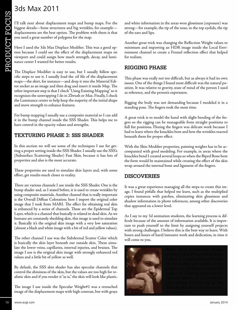
Ruben Dario Karamañites Arango was born in a small town called Parque Lefevre in a small country, Panama. He has studied and worked in Ar-gentina as a 3d artist and worked in India as a Texturing Supervisor for Skyworks Studios. He is currently the artist making 3d renderings for the Third Set of Locks inside the Panama Canal Authority.


Revit Structure 2014P
RO
DU
CT
FO
CU
S P
RO
DU
CT
FO
CU
S
12 www.augi.com January 2014
by: Scott Melching
➲When discussing the advanced applica-tions that Autodesk® Revit® offers, the opinions are varied. When dis-cussing which advanced applications
are important, the opinions are equally varied. Each discipline has its own idea of which applications are more ad-vanced—and more important—than others. But whatever dis-cipline, all can agree that Revit offers more capabilities, to more disciplines, on a broader scale … than any other software in the world. Revit has something to offer—whether in Architec-ture, Engineering, Mechanical, Conceptual Modeling, and soon, Structural Steel Detailing.
STRUCTURAL STEEL DETAILING
The concept of detailing structural steel within Revit, and further defining the idea of BIM, is becoming increasingly popular. With
the evolution of BIM, the need for “one model” by designers is becoming clearer with each project. The recent announcement of technology acquisition from Graitec, specifically its Advance Steel and Advance Concrete product lines, by Autodesk, underscores that need. While other programs exist that perform structural steel detailing, none perform it directly in the Revit environment, or even in the same language. Our hope would be that this acquisi-tion would lead to it being done directly in the Revit environment, which is certainly possible. When fully realized, this development will poise Revit to become the undisputed “King of the Hill” of the AEC industry.
As the primary focus of our business, we utilize Revit for just that purpose. Granted, “out of the box” Revit currently doesn’t lend it-self easily to this task (hence, the subject of this article); however, the vast depth of advanced Revit functions do allow for this, more easily than you might think.
Creating Advanced Families in Revit

Revit Structure 2014 PR
OD
UC
T F
OC
US
January 2014 www.augiworld.com 13
Figure 1: Structural steel detailing in Revit
VARIETY of SELECTIoN
As any detailer knows, no single connection will work everywhere on a project. The entire concept of detailing is creating whatever elements are needed to connect a structure, while ensuring those connec-tions meet AISC and/or LRFD criteria. That being said, Revit is actually the perfect tool for this. The advanced parametric functions of Revit allow for the creation of complex connection families that can be parametrically controlled, through instance parameters and/or type parameters, depending on the specific need. There really isn’t a limitation on the type of family that can be constructed in Revit using advanced family building techniques.
There have been many books published on the subject of family construction. These are a great start, but the final determination on how well you are able to develop custom Revit families will be determined by the amount of “seat time” you can devote to the task. Family construction, for the novice, isn’t an easy task, but like anything in Revit or in life, practice makes perfect. Soon, you will be creating custom families that significantly reduce the amount of time spent in a project, increasing your profitability. Eventu-ally, you will be creating custom families that allow you to offer services that no one else can offer, at prices no one else can touch, all because you put the seat time into the family creation task and developed a better mouse trap.
Figure 2: Structural connections in Revit
MoRE THAN A CoNNECToR
Detailing is much more than connections, and so are Revit families. Detailing also includes Misc. Metals. Examples of the families that can be cre-
ated in-house include parametric roof frames, stair assemblies, railing assemblies, railing brackets, gird-er and joist stabilizer plates, saddles for wood beams, girder/beam haunches, joist bottom chord exten-sions, cap plates, base plates, shear plates, angle clips, just to name a few—and all fully parametric. The beauty of Revit’s family creation tool is that what-ever the need is on a project, if can be constructed in Revit. As a fabricator, if I needed something made,
I went to the shop, picked the proper steel item, and created what-ever I needed. As a detailer, utilizing Revit, I create elements in the very same manner. The advanced capabilities of Revit really are a detailer’s dream.
Figure 3: Miscellaneous Metals in Revit
REVIT AS A PRoToTYPE TooL
Revit is perfect as a rapid prototyping tool. In the engineering of-fice, Revit can be used to rapidly assemble a rough structural frame for the engineer’s review. After this review, the frame can be final-ized based on the in-house detailer’s use of Revit for structural steel detailing. This vital step in the design process is one that is often overlooked as unimportant, but the reality is, as we move to-ward full BIM implementation, the only logical placement choice for the structural detailer is in the engineer’s office. The ability to use a detailer to create the initial model, then connect up and detail that model after the engineer’s approval, is a currently unrealized cost savings in both time and rework.
MoRE THAN A DETAILING TooL
How many of you have received the dreaded call, “Our equipment won’t fit”? Often, the need arises to co-ordinate equipment sizes and locations with building elements long before the equipment is installed. In
Figure 4: Rapid prototyping in Revit

Revit Structure 2014P
RO
DU
CT
FO
CU
S
14 www.augi.com January 2014
some cases, buildings are constructed around equip-ment. With Revit, coordination of such elements is an easy task. Many times it is possible to simply download the manufacturer’s equipment model from Autodesk Seek or other online sites contain-ing user-created Revit content. Sometimes, however, the model you need simply doesn’t exist. Create it. Revit’s advanced modeling capabilities allow, literally, anything to be made. Whether it is a grain silo, ham-mer mill, mash cooker, or yeast tank...all of these elements are easily created in Revit. As these models are created they are easily inserted into the model, and coordination becomes a routine task. In the case of a well-known Tennessee distillery, grain silos were created, in the finished configuration, and moved around the site to ensure that the final positioning allowed for the proper ingress/egress of the dozens of tractor trailers that would be seen on a daily basis. Likewise, other equipment models were created and inserted into the model to en-sure that all the elements fit properly, and even maintenance needs were addressed through this process.
Figure 5: Equipment coordination in Revit
MoRE THAN A CooRDINATIoN TooL
Revit has also been used on historic preservation projects. Friends of Old Seven (www.friendsofoldseven.org) was found-ed in an effort to spearhead the rescue and preserva-tion of the historic Seven Mile Bridge in Marathon, Florida. As part of this effort, Revit was utilized not only to reflect the current condition of the bridge, but also to show what the bridge could look like after the preservation efforts were complete. Considering that the bridge is more than 100 years old, every ele-ment created for this project was created completely from scratch, using Revit exclusively.
In addition to the existing 100+-year-old elements that had to be created for the project, the proposed final use model included ele-ments that currently do not exist, but would have to be created for this project. In both cases, Revit easily handled the creation of these elements. One of the unique elements for this project was a scale transport train to traverse the bridge, carrying tourists along its historic route. Revit’s phenomenal family creation tools even allowed for this to be created. A word of caution: Don’t open Revit expecting to find a train creation tool, and you won’t find it in the Entourage folder either. This was a completely custom element in Revit; however, the fact that it CAN be created in Revit speaks to the unilateral, unparalleled power of Revit.
Figure 6: Historic preservation concepts in Revit
REVIT AS A SALES TooL
We designers sometimes tend to forget that others either cannot, or do not, see our vision. Customers look to us to create their final vision. This is not an easy task; if it were, everyone would be a de-signer. The often overlooked visual representation tools afforded by Revit can be the perfect sales tool. It may take a bit more effort
on the front end to create a conceptual model for a serious customer, but what better representation of your proposal than a model showing exactly what you are proposing?
The amount of time spent on the model is up to each designer, but the ability to show a rendered photo-graph of the finished product or even a walkthrough video will always tell more than any conversation
can. The beauty of Revit is this: When you create a conceptual model, you have already started a working model. No more will you have to take a SketchUp model and recreate it in Revit; the conceptual model will take its place. No more will you have to convert a hand sketch to a model. That task has been eliminated and you may have gained a sale because of it.
Figure 7: Revit as a sales tool
fINAL DETERMINATIoN
It is impossible to list all the individual functions that can be performed with Revit to make your project, or your daily work-flow, stand out among the rest. Each advanced technique is ap-plied based on what you are creating, how you are creating it, and your intended final application. To say that using advanced techniques is an art wouldn’t be an overstatement. In many ways it is art, and those who can artfully use the techniques are the ones who will stand out among the rest.

Revit Structure 2014 PR
OD
UC
T F
OC
US
January 2014 www.augiworld.com 15
Scott is a former fab/erect company owner with 25 years’ experience in the industry. An avid Revit enthusi-ast and Revit Architecture Certified Professional, he is currently the owner of ST Detailing & Design, Inc. www.stdetai l inganddesign .com,American Stair Designwww.amer icanstairde sig n . com, and Phoenix Design Studios www.phoenixdesignstudios.com. Living the beach life in sunny South Florida, Scott can always be reached at: [email protected]
Below are some images of projects created completely within the Revit environment, most of them using completely custom families. The final determination on which advanced level you operate in Revit will be determined by seat time and desire. For those who dare to be different, who dare to stand out among the competition, the time will be easily given. It requires a substan-tial dedication of passion, time, and effort, and while that may not be for everyone, Revit is.
Whether your project is a simple boat house, a complex hospital, a structural frame, or a visual representation, Revit is the “capable one.” Revit isn’t just everything to one discipline—it is everything to everyone. The only limitation is your imagination. If you can dream it, Revit can help you create it.
Figure 8: Unlimited creativity in Revit
Below are some examples of custom Revit connection families used during the structural detailing process. All of these families are fully parametric, allowing single families to be used multiple times within the same project, or on multiple projects. Whether it is a shear plate, connection bolt, or a modified joist family, all are easily created in the Revit environment.

by: Walt SparlingAutoCAD 2014P
RO
DU
CT
FO
CU
S
16 www.augi.com January 2014
A necessary part of many AutoCAD® users’ day is cleaning up drawing files. Not all users set up their drawings with your use in mind, and sadly some don’t set them
up with anybody’s use in mind. There are a variety of reasons why AutoCAD users would need to clean up drawings.
• MEP users who receive updated backgrounds from architects or civil engineers.
• Architects who receive clients’ prototypical drawings that need to be converted to the architects’ standards.
• Architects who receive civil drawings to clean up for an archi-tectural site plan.
• Autodesk® Revit® users who need to clean up AutoCAD drawings before linking or, in some cases, importing them into Revit.
• Architects and engineers who clean up their drawings before sending them to an outside consultant or owner.
• Archivers who need to clean up drawings for archival purposes.
Many times, users will clean up drawings only when they have to, such as for errors (crashing drawings, inability to import into other applications), or files being too big to email, etc. By keeping the
➲cleanup process simple and automating as much as possible, it is more likely to get done on a regular basis. As we all have experi-enced, issues tend to hit on deadline day.
Everything starts with good habits and procedures. Start by keep-ing your drawings lean and efficient. Use standard layers, linetype, and text styles. Use polylines and polygons when creating objects, use explode as a last resort, and use blocks/dynamic blocks to rep-resent your drawing data. Automate your drawing standards, and object insertion processes verses copying one job to create another. Sometimes, even with good drawing practices, files will need to be cleaned up. And when dealing with outside users, cleanup is a lot more likely.
AutoCAD has some built-in tools that can help make the drawing cleanup process much easier. These tools can be used individually to handle certain cleanup tasks, or they can be used in conjunction with others to handle larger cleanups. A few of the tools that you may find useful are Purge, Audit, Selectsimilar, AND Wblock.
A brief outline of what you would use each command for and then a more detailed description of how they can be used for your clean-up purposes follows, as well as some example scripts on how to
Cleaning Up AutoCAD Drawings
January 2014 www.augiworld.com 17
AutoCAD 2014 PR
OD
UC
T F
OC
US
automate their use for drawing cleanup. Some of these commands have dialog and command line options, so depending on your pro-ductivity style, you have options. If you are a mouse dialog, rib-bon, or toolbar user, I encourage you to consider the command line versions to increase your productivity. The command line can be a powerful production option, especially when combined with shortcuts and macros.
• PURGE: Removes unused named objects, such as block definitions and layers, from the drawing using a dialog or the command line.
• AUDIT: Evaluates the integrity of a drawing and corrects some errors (command line).
• SELECTSIMILAR:A simple method to select objects based on similar properties such as layer, color, name, or lineweight.
• WBLOCK: Saves selected objects out of the current drawing or converts an existing block to a specified external drawing file.
PURGE
Over time, drawings get bloated with unnecessary and outdated in-formation. This can include unused layers, linetypes, fonts, styles, and blocks. By getting rid of these extraneous items you keep your drawings lean. Lean drawings use less memory and have less stor-age requirements, thus saving drive space, backup space, load and save times, and email overhead. Lean drawings also are less likely to become corrupt. The following types of unused named objects can be removed from the current drawing: block definitions, di-mension styles, groups, layers, linetypes, and text styles. It will also remove zero-length geometry and empty text objects. The PURGE command will not remove un-named objects (see below for un-named blocks).
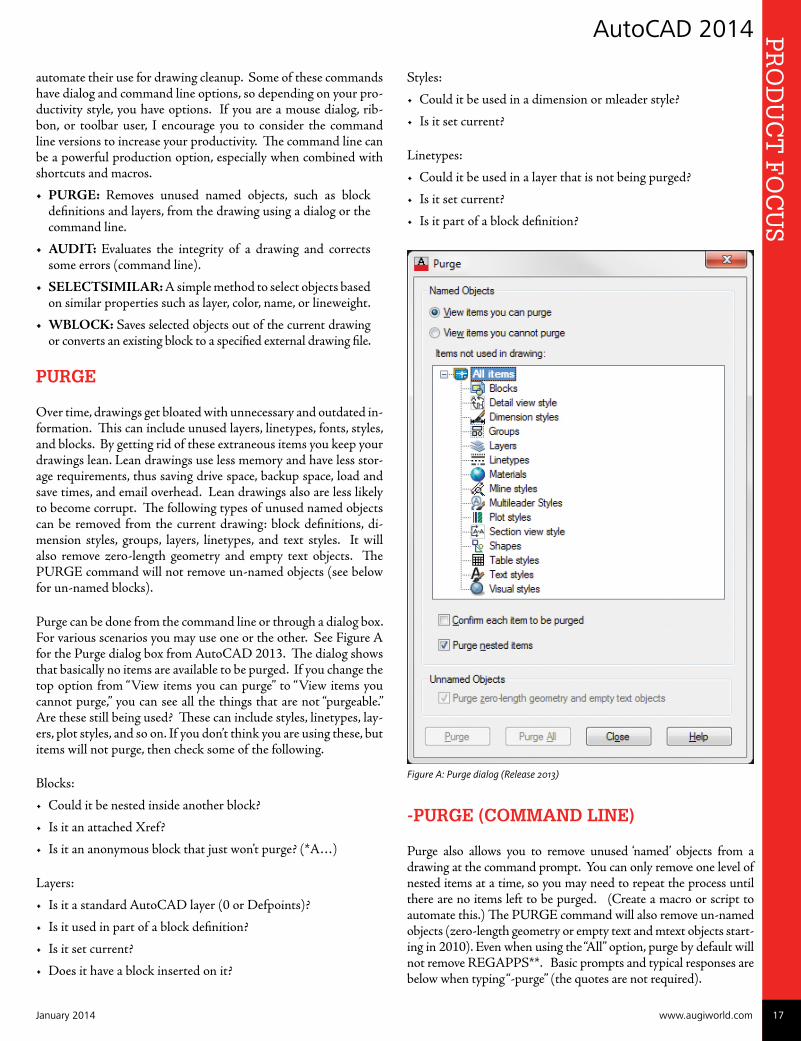
Purge can be done from the command line or through a dialog box. For various scenarios you may use one or the other. See Figure A for the Purge dialog box from AutoCAD 2013. The dialog shows that basically no items are available to be purged. If you change the top option from “View items you can purge” to “View items you cannot purge,” you can see all the things that are not “purgeable.” Are these still being used? These can include styles, linetypes, lay-ers, plot styles, and so on. If you don’t think you are using these, but items will not purge, then check some of the following.
Blocks:
• Could it be nested inside another block?
• Is it an attached Xref?
• Is it an anonymous block that just won’t purge? (*A…)
Layers:
• Is it a standard AutoCAD layer (0 or Defpoints)?
• Is it used in part of a block definition?
• Is it set current?
• Does it have a block inserted on it?
Styles:
• Could it be used in a dimension or mleader style?
• Is it set current?
Linetypes:
• Could it be used in a layer that is not being purged?
• Is it set current?
• Is it part of a block definition?
Figure A: Purge dialog (Release 2013)
-PURGE (CoMMAND LINE)
Purge also allows you to remove unused ‘named’ objects from a drawing at the command prompt. You can only remove one level of nested items at a time, so you may need to repeat the process until there are no items left to be purged. (Create a macro or script to automate this.) The PURGE command will also remove un-named objects (zero-length geometry or empty text and mtext objects start-ing in 2010). Even when using the “All” option, purge by default will not remove REGAPPS**. Basic prompts and typical responses are below when typing “-purge” (the quotes are not required).

18 www.augi.com January 2014
AutoCAD 2014P
RO
DU
CT
FO
CU
S
Enter type of unused objects to purge: “A” Enter name(s) to purge: “*” Verify each name to be purged? “N”
** One item that will need an extra step is “REGAPPS.” Re-gapps are a byproduct of objects with extended entity data (xdata). When you delete an xdata object, a REGAPP ID re-mains. To remove these, you must do it from the command line. –Purge <enter> R <enter> * <enter> N <enter>
ANoNYMoUS/UN-NAMED BLoCKS
Annoying items that creep up quite often are the infamous “un-named”or “anonymous” blocks or groups. These show up as *A123, *A124, *X12, *D13, etc. You may have noticed that when you ran Audit, there were far more blocks in your drawing than you thought there should be. This builds over time as you continue to use old projects for new work and when you use outside vendors or consultants’ drawings. It can be very frustrating to find 1,000 blocks in a drawing that do not show up in your block list and will not purge! Some of these are created by AutoCAD for hatch patterns [*X nnn], associative dimensions [*D nnn] and some are created by AutoLISP routines. I find that this happens a lot when working with drawings from civil and architectural offices. To re-
move the blocks that are not being used, you can use the Wblock or –Wblock command (see WBLOCK).
*Unnn = anonymous blocks *E### = anonymous non-uniformly scaled blocks *X### = anonymous hatches *D### = anonymous dimensions *A### = anonymous groups
AUDIT
From time to time you will get a file that requires recovery to open it, or during a working session you will get an error suggesting that a recovery may be necessary. One way to keep your drawings healthy is to be proactive and run the Audit command. Audit is a good maintenance tool to run on your drawings to keep them clean of most errors. When you get drawings from outside firms, this is a must-do step. If a drawing contains errors that AUDIT cannot fix, try using RECOVER to open the drawing and correct its errors.
Audit is a command line tool. Following are the prompts and options.
• Type “Audit”
• The following prompt is displayed.
Fix any errors detected? [Yes/No]. You would typically choose “Yes,” unless you’re just looking to see if the draw-ing has errors.
• When the routine is done it will give you a status report of how many objects it audited and how many errors it found and corrected. Running Purge prior to an Audit will often reduce the overhead of auditing items you do not intend to keep anyway.
Note: If AUDIT or RECOVER do not work and you’re still get-ting errors, try inserting the troubled drawing into a clean empty drawing, EXPLODE it, PURGE, and do a SAVEAS.
SELECTSIMILAR
How many times have you worked on a drawing where you were just looking to get just line work or just text isolated on a layer? You try to freeze or isolate text or dims only to find out that half the drawing disappeared. This is a common issue with various trades where everything associated with a specific topic is on a single layer. For example, an architectural drawing has a ceiling plan layer: “A-CLG” that includes the grid, the lights, the diffus-ers, the notes, and the dimensions all on one layer—in different colors (ugh!). Or how about an HVAC drawing that has the main ducts, flex ducts, and supply grille/diffuser blocks all on a single “M-SUPPLY” layer? Sometimes you just need the lights or grid

January 2014 www.augiworld.com 19
AutoCAD 2014 PR
OD
UC
T F
OC
US
or supply grille locations, but doing layer isolate (another handy tool) gives you everything. Selectsimilar to the rescue!
Selectsimilar provides you with a way to select objects based on similar characteristics. Objects based on properties such as layer, color, or lineweight can be grabbed quickly with this command. Access the command by typing “selectsimilar” at the command line or from the right-click shortcut menu after you’ve selected an ob-ject. What is selected will depend on the current SELECTSIMI-LARMODE value.
If you have objects with a different color being included when selecting objects based on color, note that objects are considered similar if they are set to “BYLAYER.” This also includes proper-ties such as linetype, lineweight, plot style, material, and trans-parency. For example, you may get text or line work selected even though they are not the same color if their color property is set to BYLAYER.
To select similar objects, you can type “SELECTSIMILAR” (cre-ate a shortcut like “SS”) or select an object that represents the cat-egory of objects you want to select, right-click, and choose “SE-LECT SIMILAR.”
Note:Only objects of the same type (lines, circles, polylines, etc.) are considered similar. You can change other shared properties with the SELECTSIMILAR command, using the “SE” (Settings) option.
The Settings dialog box controls which properties must match for an object of the same type to be selected.
• Color–Considers objects with matching colors to be similar.
• Layer –Considers objects on matching layers to be similar.
• Linetype–Considers objects with matching linetypes to be similar.
• Linetype scale– Considers objects with matching linetype scales to be similar.
• Lineweight– Considers objects with matching lineweights to be similar.
• Plot style –Considers objects with matching plot styles to be similar.
• Objectstyle– Considers objects with matching styles (such as text styles, dimension styles, and table styles) to be similar.
• Name– Considers referenced objects (such as blocks, xrefs, and images) with matching names to be similar.
SELECTSIMILARMoDE
To automate the SELECTSIMILAR command in a macro or script you would use SELECTSIMILARMODE. As with many AutoCAD commands, each combination of options has a bit code (numerical value). Some examples:
• Select color only = 1
• Select Color and Layer = 3
• Select Color and Name = 129
• Select Layer and Name = 130
To determine these values, run the SELECTSIMILAR command, type SE, and toggle the options. Then run the SELECTSIMI-LARMODE command to find the numeric value of these options.
I use “130” most often. This allows me to isolate named ob-jects such as “ Text” on the same layer. Using Selectsimilar to

20 www.augi.com January 2014
AutoCAD 2014P
RO
DU
CT
FO
CU
S
select a piece of text on a layer would select all text on that layer, no matter what style or color it is. Selecting a polyline with the 130 setting would select all polylines on that layer, no matter what color. Selecting a block would only select other blocks with the same name on that layer. Each of these is use-ful when selecting items that you may wish to delete or move to another layer.
WBLoCK
The WBLOCK (Write Block) command is probably best known for saving selected objects or a block within a drawing to an ex-ternal drawing file. WBLOCK can be a powerful cleanup tool in your arsenal. Probably the most common method of drawing extraction is to type WBLOCK and select the options in the dia-log to save parts of a drawing to a specific drive and folder.
The dialog gives you three options: You can choose a block within the drawing, the entire drawing, or objects that you want to selec-tively ‘write out’ of the drawing. When selecting objects, you select a base point, select the desired objects, and then select a new name and path where your file is to be saved.
You also have the option to access the quick- select dialog to select items via a properties filter. You can also use WBLOCK from the command line. To use WBLOCK at the command line, add a hyphen in front of the command, e.g., -WBLOCK. It will then prompt you to enter a name of an existing block or define a new drawing. You have three options here.
• Type an existing block name within the drawing that you want to “write out.” (Use if you have created a block in the current drawing and you want it now saved out to your mas-ter library or a project folder.)
• Hit enter and a new drawing will be created with the name you entered in the previous dialog. You will be able to select an insertion point and select the objects to write-out. (Use if you want to selectively write out objects to a new drawing file.)
• Type an asterisk ‘*’ which will cause it to write out the en-tire drawing. (Use to do a mass cleanup of your drawings in a single sweep.)
When cleaning up client drawings or your own from rogue data that has been inserted (often through copy-paste operations), this is a powerful tool. This handy method writes the entire drawing to the new output file, except for unreferenced symbols. Model space objects are written to model space, and paper space objects are written to paper space.
If you use the dialog to do your WBLOCK operations, even when you selectively choose your objects, it takes all the junk with it that you already can’t purge.
Try this:
• Open a drawing that has unpurgeable items (bunch of *A1nnn blocks) say “A1.DWG”.
• Turn On, Unlock, and Thaw all your layers.
• Type WBLOCK and choose the “Objects” option.
• Select everything in your drawing (crossing, window, etc.).
• For the Destination, choose a new file name “A1-Objects.DWG.”
• Type AUDIT and see how many objects are in the drawing.
• Compare your size to the original A1.DWG.
Then try this, with the drawing still open:
• Type WBLOCK and choose the “Entire drawing” option.
• Choose a new name “A1-Entire.DWG.”
• Type AUDIT and see how many objects are in the drawing.
• Compare all your sizes now.
• : )
WblockResults:
Before:
(Already Purged), Audit reports 114,900 objects and 3,478 blocks - 4,327 KB.
After:
WBLOCK (Entire drawing option OR –Wblock with “*”), Audit reports 4,600 objects 71 blocks - 291 KB (93 percent smaller).
The second option removes all those unused and unpurgeable items that the first would not. See how much faster your drawings open, save, and close.
++ Be careful, though, as both of these methods will remove any Layer States in the drawings.

January 2014 www.augiworld.com 21
AutoCAD 2014 PR
OD
UC
T F
OC
US
“-WBLOCK”notcuttingit?
Sometimes even the –WBLOCK command will not reduce the size of your files. For these continually nagging files, try the DXFOUT command.
• DXFOUT the file
• Open the DXF
• PURGE
• SAVEAS
AUToMATE YoUR CLEANUP PRoCESS
By combining a mixture of the tools above along with some other AutoCAD commands, you can reduce the cleanup time dramati-cally with Macros, Scripts and Scriptpro. Although macros have been my standard automation tool, it is often easier to use scripts so that you can do batch automation with Scriptpro, a free utility from Autodesk that can be found on the Autodesk website.
Example macros:
SuperSave:
^C^C -PURGE;A;*;N; -PURGE;A;*;N;AUDIT;Y;-PURGE;A;*;N;ZOOM;E;SAVE;CLOSE;
Superpurge: (includes Regapps and WBlock)
^C^C-PURGE;A;*;N;AUDIT;Y; -PURGE;A;*;N;-PURGE;R;*;N;AUDIT;Y;-PURGE;A;*;N;-WBLOCK;
SampleMacroinCUI
DeleteSimilar:
^C^CSELECTSIMILARMODE; 130;SELECTSIMILAR;/ERASE;P;
Note: be sure to define your “similar” mode in your script/macro by setting the “selectsimilarmode” value.
If you have to commonly bind and save your drawings to an older version (SAVEAS), you can have a macro set up just for that.
^C^CZ;E;-PURGE;A;;N;AUDIT;Y;-PURGE;A;;N;-PURGE;R;*;N;-PURGE;A;;N;BINDTYPE;1;-XREF;B;*;SAVEAS;2004;
There is not one “super cleanup” command or macro tool that will
work for everyone, but you can get pretty close to what will equate to your super tool with a little thought. Look at your cleanup pro-cess—what are you repeating or what is client “A” always requiring as part of the cleanup process? Automate these items using the tools above and tweak as necessary for each client.
Let’s say you want one ultimate macro that varies slightly by client, but is pretty consistent overall. Some things you may want:
• Set consistent units – Use the Units command options.
• Want the drawings to be lean and error free – Use Audit and Purge.
• All items to be color by layer – Use the SETBYLAYER com-mand (Thaws and Unlocks all layers).
• Want the layers to be consistent – Use client-specific Layer States.
• For clients who use the standard AutoCAD font style as “their” standard – Rename it to ARCH-STANDARD.
• Saved when zoomed to extents – Use Zoom, extents.
The below macro would accomplish that and would take literally sec-onds to run.
^C^C-UNITS;4;16;1;0;0;N; -LAYER;T;*;ON;*;UNLOCK;*;; -PURGE;A;;N;AUDIT;Y;-PURGE;A;;N;SETBYLAYER;ALL;;YES;YES;Z;E;-LAYER;A;I; F:/CUSTOM/LAYER_STATES/CLIENT_NAME/CLIENT.LAS;R;DESIRED_STATE;;; -RENAME;S;STANDARD;ARCH-STD;Z;E;SAVEAS;
Items in RED would vary by client.
If every job is totally unique for you and you need a generic macro, you would remove the layer states option above and you may want to skip the SETBYLAYER command as it may give undesired results when plotting.
After the macro runs, you could use some of the other tools men-tioned above to clean up the drawing even further.
Standardization, automation, and training are the best tools for in-creasing your efficiency in any process in AutoCAD. Once you find out which tools (commands/macros/scripts/LISPs) are your go-to items and you have a set process, you can whip through the drawing cleanup process. Over time I have standardized on many of the above commands and macros, but I am always looking for new options to reduce any repetitive or time-wasting tasks.
TEST
Test, Test, Test! When incorporating new tools and methods into your arsenal or cleanup process, be sure to test on non-production drawings or at least copies of drawings before you implement these as standard tools. Each office may have unique file requirements that need to be considered when implementing these processes.

22 www.augi.com January 2014
AutoCAD 2014P
RO
DU
CT
FO
CU
S
oTHER TooLS
This article by no means covers all the tools available for drawing cleanup, but these are some very useful ones that, when used in-dividually or in conjunction with others, can make your drawing cleanup process go much faster. As there are a multitude of options and tools available in AutoCAD for cleaning up your drawings, I encourage you to look into some of these other powerful commands and AutoCAD options.
SETBYLAYER:
Sets selected objects to color BYLAYER (as they should be). You can also use this to change the linetype, lineweight, material, and transpar-ency to BYLAYER. Like SELECTSIMILAR, SETBYLAYER has a mode value (SETBYLAYERMODE) that can be set (i.e., for color only the value is 113). I typically do NOT change linetype to BY-LAYER as it is a common scenario to have a linetype set to by entity but on the same layer with other line types.
FILTER:
To create saved selection sets.
QUICK SELECT (QSELECT):
Use to select different types of objects that share the same proper-ties such as color, linetype, plot style, lineweight, transparency, etc., and build a selection set on the fly.
OVERKILL:
Use to remove duplicate items in a drawing that share the same space (i.e., doors, walls, lights, etc.) right on top of one another. This often happens when binding similar XREFs or copying items and inadvertently selecting the same origin and destination point and not realizing it.
Clean, efficient drawings make for happy users!
Walt Sparling has worked in the building design industry for 25+ years, starting as a hand drafter. He moved on to CADD in the mid 1980s and then into CADD and networking training and consulting. Walt has served as project manager and designer in the mechanical and architectural realms and currently works with an electrical engineering firm in Tampa, Florida. In his “spare” time, Walt maintains a couple of blogs and a personal website: FunctionSense.com and waltsparling.com
And Here’s How to…Edit Quick
Properties ContentRollover Tips are great (see AUGIWorld October 2012 for editing tips), but if you need to change a property of the se-lected object(s), simply customize the Quick Properties con-tent. This is another tidbit I shared in my Autodesk Univer-sity lab last month on how to add Background Mask to the Quick Properties content of Mtext.
HowtoAddaBackgroundMaskToggletoQuickProperties
1. Click on any Mtext, then click Quick Properties on the Status bar.
2. Click the Customize button in the top right corner to open the CUI, displaying three vertical panels. [In the middle section, Mtext is already highlighted.]
3. In the Properties section on the right, check the box for Background Mask.
4. Click OK to save your changes and close the CUI.
5. Click an Mtext object, then click the Background mask option in Quick Properties.
6. Click the ellipses button to open the Background Mask dialog box.
7. Check the box for Use Background Mask as well as the box for Use Drawing Background Color, as shown in the figure.
8. Click OK to close the Background Mask dialog box, then close Quick Properties.
When you move the text on top of another object, you see the mask effect.
Michael E. Beall (B. Arch.) is an Autodesk Authorized Author and the owner of CAD Trainer Guy, LLC. He has been presenting onsite CAD training around the planet for more than 30 years. Contact him at [email protected] or give him a call at 502.500.2267.


PR
OD
UC
T F
OC
US AutoCAD Architecture 2014
PR
OD
UC
T F
OC
US
24 www.augi.com January 2014
by: Melinda Heavrin
A point cloud is basically a large collec-tion of points that are placed on a three-dimensional coordinate system. Point cloud files greatly speed the design pro-
cess by providing real-world context where you can re-create the referenced objects or insert additional models. Point clouds are derived from raw data gathered by using a 3D scanner to obtain points from such things as buildings, topographies, or manufactured items.
Before you can use the data in your drawing, however, it needs to be converted to a point cloud file. This process is sometimes referred to as indexing. You can use AutoCAD® Architecture to convert raw scan files to an ISD or PCG format. You can use Autodesk’s ReCap™ product to convert raw scan data to an RCS format. Autodesk ReCap can also save files in an RCP format that serves as a project file that references multiple RCS files. Both formats can be attached to an AutoCAD Architecture drawing.
CREATING PoINT CLoUDS fRoM SCAN fILES
A scanned data file can be converted to a point cloud file that can then be attached to your drawing. To do this, begin by clicking the Insert tab of the ribbon, Point Cloud panel, and then select Create Point Cloud. In the Select Scan File dialog box, find and select one or more files that you want to use to create point clouds. You can choose the following formats: LAS, XYB, FLS, FWS, XYZ, TXT, ASC, PTG, PTS, PTX, CLR, and CL3. In the Create Point Cloud File dialog box, enter the settings for the imported point cloud, including whether to merge the files, where to store the point cloud files, and what point cloud file format to use (see Figure 1). If you import more than one file, you can merge them by selecting Merge All Scan Files into a Single Point Cloud. When selecting what point cloud format to use, you can select the Autodesk format (PCG) or Ambercore (ISD). With PCG files,
Point Clouds
➲

AutoCAD Architecture 2014 PR
OD
UC
T F
OC
US
January 2014 www.augiworld.com 25
you can import such properties as color, intensity, and normal and custom attributes.
Now, click the Create button to start the process, which can take minutes or hours, depending on the file size. The dialog box is minimized, so you can con-tinue to work while the scan is in progress. When the process is complete, the Status column in the table changes to “Click to Attach.”
To attach the new point cloud file to the current draw-ing, you can either click the Click to Attach message or click the link in the balloon message on the task bar. While point cloud creation is in process, hover the pointing device over the point cloud icon in the drawing status bar in order to view the status of the background point cloud creation. To cancel a point cloud creation process, while the raw point cloud scan files are being indexed, you can either right-click the point cloud icon in the drawing status bar and select Cancel Point Cloud Creation, or you can click Cancel in the Create Point Cloud File dialog box.
ATTACHING PoINT CLoUDS
To attach a point cloud file as an external reference, begin by click-ing the Insert tab of the ribbon, Point Cloud panel and then se-lect Attach. In the Select Point Cloud File dialog box, find and select an ISD, PCG, RCS, or RCP file to attach to the drawing and click Open. In the Attach Point Cloud dialog box, specify your preferences for insertion point, scale, and rotation (see Figure 2).
If you would like to prevent the attached point cloud from being moved or rotated, select Lock Point Cloud. You can control the individual scan file settings in the attached RCP file. You should turn on this setting if you do not want your drawing to be affected by changes to the on/off status of individual scan files that are ref-erenced in the reality capture project (RCP) file. To do this, at the Command prompt, enter POINTCLOUDVISRETAIN. Then enter either 0 or 1. For zero (0), the drawing inherits the most recent on or off status of individual scan files referenced by the attached RCP file. For one (1), the drawing retains the on or off status of individual scan files at the time the RCP file was attached.
WoRKING WITH PoINT CLoUDS
Once a point cloud is attached to a drawing, you can modify it, use it as a guideline for drawing, change its display, or apply a color mapping to distinguish differ-ent features. You can modify an unlocked point cloud in several ways.
• Filter un-needed points by clipping – You can cre-ate one or more clipping boxes to show only the most relevant areas of the point cloud. Drag the clipping boundaries to change the display and turn off or invert the clipping filters as you work.
• Modify point cloud density – You can manage program performance and visual noise by increas-ing or decreasing the number of visible points.
• Standard editing operations – You can cut, copy, paste, move, scale, rotate, stretch, and erase a point cloud.
• Edit properties – You can change general properties such as color and layer in the Properties window. You can also modify the insertion point, rotation, and scale as well as turn locking and clipping on or off and con-trol whether the color is derived from the source or the current color settings.
Figure 1: Create point cloud
Figure 2: Attach point cloud

AutoCAD Architecture 2014P
RO
DU
CT
FO
CU
S
26 www.augi.com January 2014
• Use components as a reference when drawing – You can turn on the Node object snap, and snap to individual points as you draw. You can also snap to the insertion point.
• Use color stylization – You can use color stylization to help you analyze features within the point cloud. You can retain the original scan colors or specify color stylizations that are based on objects, point orientations, or intensity.
For point cloud files that inherit intensity values, intensity styliza-tion helps distinguish between features such as foliage and build-ings. Use different color schemes such as Spectrum for more com-plex images or Grayscale for simpler visualization. You can use color mapping on both locked and unlocked point clouds. You can print a point cloud and retain the color stylizations in all visual styles except for 2D wireframe and wireframe. It is important to note that the MIRROR3D command copies and moves a point cloud, but does not mirror it. You cannot explode a point cloud.
CHANGING PoINT CLoUD DENSITY
You can control the number of displayed points to help you man-age program performance and decrease visual noise. You can change the maximum number of points in the drawing, which is controlled by the POINTCLOUDPOINTMAX system variable only for 64-bit operating systems. Increasing the limit improves visual fidelity for the point clouds, whereas lowering the limit im-proves system performance. This option is disabled on 32-bit sys-tems, which are limited to 1.5 million points. Begin by clicking the Application menu and select Options. In the Options dialog box, 3D Modeling tab, drag the Maximum Point Cloud Points per Drawing slider to change the number of points that can be dis-played in the drawing.
You can change the density of all displayed point clouds. To do this, begin by clicking the Insert tab of the ribbon, Point Cloud panel, and select Density slider (see Figure 3). You can now either drag the Density slider to increase or decrease the percentage of cloud points that are displayed in the drawing or you can enter a value that represents a percentage of the maximum number of points set by POINTCLOUDPOINTMAX.
You can change the density of displayed point clouds during Pan, Zoom, or 3D Orbit. Lowering the real-time density degrades the point cloud display during panning, zooming and orbiting, but makes those operations quicker. To do this, begin by clicking the
Insert tab of the ribbon, Point Cloud panel, and then select Real-time Density slider (see Figure 3). You can now either drag the slider to increase or decrease the percentage of cloud points that are displayed during real-time pan, zoom, and 3D orbit, or you can enter a value that represents a percentage of the maximum number of points that can be displayed in the drawing during pan, zoom, or 3D orbit. This value represents a percentage of the maximum number of points set by POINTCLOUDPOINTMAX.
PoINT CLoUD CLIPPING
If needed, you can clip or hide a portion of a selected point cloud. If you wish to create a 2D rectangular or polygonal point cloud clipping boundary, then in the drawing area, select the point cloud. Now, on the Point Cloud tab, Clipping panel, select Create Clip Box flyout. Now, you can either Select Rectangular or Select Po-lygonal on the flyout (see Figure 4). If you Select Rectangular, on the XY plane of the drawing area, specify diagonal corners of the rectangular clipping boundary and press Enter. If you Select Po-lygonal, on the XY plane of the drawing area, specify three or more segments for a closed polygonal boundary and press Enter. The point cloud points that fall outside the defined clipping boundaries are hidden.
Both rectangular and polygonal clipping boundaries can be re-shaped. In the drawing area, select a point cloud. Select a grip on the clipping box and when it turns red, drag it to change the clip-ping box shape. The point cloud display is updated after the drag operation is complete.
If you wish to convert a polyline to a 2D clipping boundary, in the drawing area, select the point cloud. On the point cloud tab, clipping panel, Create Clip box flyout, then select Polyline (see Figure 4). In the drawing area, select a polyline to define the clip-ping boundary. The polyline can be open but must have straight segments. The point cloud points that fall outside the defined boundaries are hidden. Sometimes, however, you may find it use-ful to have a polyline that coincides with a 2D point cloud clipping boundary. To create the polyline, enter POINTCLOUDCLIP at the command prompt. Then Enter p (generate Polyline). Now, in the drawing area select a point cloud. The new polyline will inherit the current layer, linetype, and color settings.
Figure 3: Adjust point cloud density

AutoCAD Architecture 2014 PR
OD
UC
T F
OC
US
January 2014 www.augiworld.com 27
A 3D point cloud clip box can be re-shaped based on the bounding box. To do this, select a point cloud and then click the Point Cloud tab on the ribbon, Clipping panel, then select Clip Box. A clipping box that is the same size and shape of the point cloud bounding box is displayed. If the point cloud already has a clipping box that has been modi-fied, you can choose whether to restore the default clipping box or retain the modifications. To adjust the clipping box, drag the grips using either Standard grip (square) or Height grip (triangle). Standard grip resizes the length and width of the clipping box along the XY plane of the point cloud object. Height grip resizes the height of the clipping box along the Z axis of the point cloud object.
The point cloud clipped view can be turned on and off within a drawing. When the ribbon button is highlighted, select a point cloud clipping boundary or clipping box. Click the Point Cloud tab on the ribbon, Clipping panel, then select Show/Hide. This turns the view on or off. Sometimes instead of turning it on or off, you may need to remove it completely. Select a point cloud and click the Point Cloud tab on the ribbon, Clipping panel, and then select Delete Boundary. Select the clipping boundary or clipping box that you want to remove and press Enter.
Figure 4: Point cloud clipping boundary
CoLoR MAPS THAT DISPLAY PoINT CLoUD INTENSITY
Some types of scan files contain color intensity data that can be retained in the point cloud. These file types include LAS, PTG, PTS, PTX, CLR, and CL3. To assign colors to map the point cloud intensity, in the drawing area select a point cloud that con-tains intensity data. Click the Point Cloud tab on the ribbon, Visualization panel, then select Intensity Color Mapping. In the Point Cloud Intensity Color Mapping dialog box, adjust the fol-lowing settings.
Melinda Heavrin is a CAD Coordinator & Facility Planner for Norton Healthcare in Louisville, Kentucky. She has been using AutoCAD Architecture since release 2000. Melinda can be reached for comments and questions at [email protected]
Color scheme – Select a color scheme to help illustrate the point cloud intensity mapping. Colors range from Spectrum to grayscale and single colors.
Color ramp – Drag the sliders to define the color range to use in the mapping.
Intensity minimum and maximum – Enter values between 0.000 and 1.000 to specify the percentage of intensity values to be dis-played using the color map stylization. These values represent the high and low values of the entire range of intensity values associ-ated with the selected point cloud. Points with intensity values that are outside the limits you specify are displayed using the origi-nal scan colors.
Once that’s complete, click Apply to test how the settings affect the selected point cloud.
If you are not a fan of the color scheme, you can change it in the Proper-ties palette. If the Properties window is not displayed, select any object and then right-click the object and select Properties. In the drawing area, select the point cloud. In the Properties window, under Point Cloud Visualization, Intensity Color Scheme box, select a different option. You can also perform this function using the ribbon, which I find a little easier. In the drawing area, select the point cloud. Then click the Point Cloud tab on the ribbon, Analysis, then select Intensity. Now you can select a color scheme under the Spectrum flyout or select Intensity Color Mapping and select the color scheme you want to use (see Figure 5).
Figure 5: Point cloud intensity color mapping

Revit ArchitectureP
RO
DU
CT
FO
CU
S P
RO
DU
CT
FO
CU
S by: Jennifer Storey
28 www.augi.com January 2014
Advancement—we hear about it every day. How radical are the advancements we are making in the Architecture En-gineering and Construction (AEC)
industry; how fast advancements are coming; how much we have embraced advancements; which firms
or companies serve as ambassadors for advancement…
According to the Merriam-Webster definition, advancement is “the act or result of making something better, more successful, etc.”
How do we measure better or more successful? Looking again at the definition of better, it’s “higher in quality - more skillful - more attractive, appealing, effective, useful, etc.” And successful: “having the correct or desired result - ending in success.”
According to these definitions, it is evident that we are advancing: We create attractive buildings that are useful and “end” in success. One can even win an award for building design or construction quality.
Yet these are subjective determinations; we do not yet have a simple, quantifiable measurement for advancement. And such determina-tions can be relative to a person, company/firm, or project team.
For example, when we want to advance within our organi-zations, we have to demonstrate that we are productive. If we are not productively adding value to our company, we will not advance. So should productivity be a measurement for advancement?
For all our sakes, let’s hope not. Because according to U.S. Department of Commerce data, the construction industry has not become more productive in the last 50 years—an ac-complishment made even more disconcerting when compared to other non-farm industries, which more than doubled their respective productivities.
➲
The Potential for Advancement
in AEC

Revit Architecture PR
OD
UC
T F
OC
US
January 2014 www.augiworld.com 29
Productivity in and of itself isn’t a fair quantitative measurement be-cause our work has changed, and quite dramatically. We must recog-nize that building projects today are more complex and require big-ger teams to complete them, while at the same time project budgets are tighter and schedules are shorter than they used to be.
Yet we still think we can build projects the same way we always have. An architect designs and draws the building, a contractor builds the building, and an owner lives with the building.
I submit that this “paradigm change” is the main reason our in-dustry’s overall productivity appears to have gone in the wrong direction. We have just started to address these added complex-ities by utilizing technology, teaming for the design and con-struction of a building, and changing the way we think about a facility overall.
In most industries, the answer to becoming more productive lies in the use of technology. And the same should prove true for the AEC industry.
This is a very exciting time to be in the AEC industry because we have never seen more ability to change and grow. It is a time with the potential for great advancements in many ways. Our technol-ogy is advancing in ways we would never have thought imagin-able—such as visualization capabilities, analysis accuracy, and even the speed with which it functions.
When we switched to computer-aided design, it was just a shift in the tool we were using to do the same job. You would draw a line with a computer instead of drawing it with a pencil.
Now we are building our buildings virtu-ally. We are coordinating them fully before in-field physical construction even starts. These changes allow for pre-fabrication within construction. The ability to do these things would not be available to us without the use of Building Information Modeling (BIM).
The owners have to see and understand what their space will look like to allow us to pre-fab parts of the building. They will not have the opportunity to walk through the construction site and ask for more outlets in the wall—or move the medical gases to different locations in the headwall—when they see the rough-ins and get a better un-derstanding of the physical space. They have to have this understanding of their space early to allow us to fabricate and in-stall quickly and efficiently.
The use of BIM for design and construction has started us on a road to collaboration the likes of which we have never experienced before. The designers want the input from the construction team, the people who know how the building will physically go together. The contractors want a better understand-ing of the design intent so they can achieve it. The team, design and construction, is excited when they can come up with a new innovative way to achieve the design intent that saves the project time or money. Working together, they are more likely to come up with these innovations because they bring different skills to the table as well as different ways of thinking.
Teaming does not have to mean Integrated Project Delivery; it doesn’t have to be contractual. It can be a “way of doing things.” We are teaming, contractually or otherwise. We hear about “IPD-like” projects happening every day. These project delivery meth-ods/approaches are a step in the right direction. I have listened to many architects comment that they do not dread going to job meetings anymore. They do not feel the contractor will point at them and say they didn’t know what they were drawing or that they messed up. Teams are no longer asking who is at fault in a job meeting. They are working for the better of the project, and the question has become, “How do we fix it?” The more teaming be-comes the way of construction, the better the buildings we provide to owners and end users.
Another advancement taking place is recognition within our in-dustry that our work is not complete when the Architecture/En-gineering/Construction portion is complete. Rather, we’re now looking at operations of the building.
Estimates show that initial building cost, design, and construction represents only 15 percent of total building cost. So designing and constructing a facility for the long term is where true savings—some 85 percent of overall building cost—will be recognized.

Revit ArchitectureP
RO
DU
CT
FO
CU
S
30 www.augi.com January 2014
To truly advance as an industry, we must consider long-term op-erations. We can’t just build it and walk away.
Expanding operations is where we will realize true advancement. Until we consider operations and facilities management of the building during the entire project—before we start design—we will not be able to fully realize our advancement potential.
This means we have to educate our building owners on the need for BIM standards that incorporate their facility manage-ment needs.
I believe that as an industry, we are recognizing this fact. In signing up for Autodesk University classes this year, I noticed that a much larger portion of classes are addressing FM needs. I also noticed how quickly these classes filled up. We are all thriving for knowledge in this area, so we are interested in this advancement.
We must quit viewing construction of a building as the end game. The building itself is just the beginning. We will truly advance when we share knowledge and information gained dur-ing design and construction that can be used for the lifecycle of the building.
Jennifer Storey, AIA, EDAC, is chief operating office for Buric Global, LLC, Chagrin Falls, Ohio, which provides enhanced project controls including critical path method (CPM) scheduling, BIM services, and owners’ representation. She previously worked as senior healthcare architect at Leo A. Daly in Los Angeles, California, and project architect and BIM manager at Bostwick Design Partnership in Cleveland, Ohio. Jennifer is a member of the American Institute of Architects, a Revit certified professional, and she holds the Center for Health Design’s Evidence-Based Design Accreditation certification. She earned her architecture degree from Kent State University.

Navisworks Manage 2013 PR
OD
UC
T F
OC
US
PR
OD
UC
T F
OC
US
by: Mark Hunter
January 2014 www.augiworld.com 31
➲From the beginning, some of the most valu-able information that comes from 3D mod-els is also some of the simplest to retrieve. Visualization and quick precise measure-
ments are the things I have been asked to provide more than any other piece of information during my career.
Thanks to the measuring and sectioning tools in Navisworks® Manage, it is easier and faster than ever to provide your team with the information they need. And because these features are also in Navisworks Freedom and 360 Glue, you can help lighten your workload by empowering your team to find the information themselves.

Navisworks Manage 2013P
RO
DU
CT
FO
CU
S
32 www.augi.com January 2014
MEASURE TooLS
The measuring tools in Navisworks have some simple commands that make them very powerful. But first we’ll look at the measure window and how to read it.
Figure 1: Measure window
The measure window consists of four rows: Start, End, Differ-ence, and Distance. At the very top are all the measure tools: Point to Point, Point to Multiple Points, Point Line, Accumu-late, Angle, Area, Shortest Distance, Clear, Transform Objects, and Convert to Redline. These same tools can be found under the Review tab.
The measuring tool is pretty straightforward, but there are a few things you should understand before measuring. The Start and End rows have three columns. These columns represent from left to right the X,Y,Z coordinates of your measurements based on where your 0,0,0 point is in the project. Navisworks gives you the option to lock your measuring direction to the X,Y,Z axis and parallel or perpendic-ular to a surface. This is important to remember because if you want to pull certain measurements from your Navisworks model, you need to pay attention to how you export your models or how you position them in Navisworks.
For example, if I want to get the flat dimension between two pipes running straight but at different elevations, I could use the Point to Point measuring tool. After selecting a point on my first pipe I can hit X or Y on my keyboard and Navisworks will lock the mea-surement to that axis. But what if my Autodesk® Revit® model was rotated 15 degrees and I exported using Shared Coordinates? The X,Y axis in Navisworks would be off, so if I tried this measurement with a rotated model it wouldn’t work. I would either need to zero
out my rotation in Navisworks by selecting the entire model and opening its Units and Transform, or I could change the exported setting in Revit to export using Project Internal coordinates.
Another way I could get that measurement if my model was not rotated is by using the shortest distance tool. After selecting the two pipes I can hit the Shortest Distance measurement and Navis-works will (frustratingly) change my view and then pull that mea-surement. The measurement will be at an angle which is not what we were looking for, but if you look in the Measure window in the Difference row you can see the flat measurement along the X axis. The measurement can be very different from the shortest distance measurement as shown in Figure 2
Figure 2: Reading the difference
SPEED SECTIoNING
Sectioning can be a very useful tool during coordination. Some-times you will have the luxury of sectioning before a meeting and preparing views, and other times you will need to section on the fly while everyone is waiting. There are quite a few tools for section-ing, but I will only cover the ones I have found most applicable to BIM coordinations.
When preparing views before a meeting, Saved Viewpoints are great because they will keep your section cuts, redlines, and hide properties so you can set up views that will clearly display an issue.
During a meeting I recommend having the Section Plane Settings window open even when sectioning is turned off.

Navisworks Manage 2013 PR
OD
UC
T F
OC
US
January 2014 www.augiworld.com 33
Mark Hunter is a BIM Manager for C.W. Driver, a large general contractor in Southern California. The firm is highly regarded throughout the design and construction industry for implementation of BIM innovations on each project, and for creating customized software plug-ins to increase the efficiency of the latest software releases. Mark has a video showing how section cuts can be pushed in walkthroughs to the extreme on his blog: ht tp://navisninja.blogspot .com/ Mark can also be reached at [email protected] , or at 909.945.1919.
Figure 3: The sectioning planes window can be turned on under View/Windows/Sectioning Plane Settings
Sectioning on the fly can be fast and easy. You can try to use the Top, Bottom, Front, Back, Left, or Right standard sections and then move them to the desired location. At times it is also helpful and faster to use the Align to View cut, but your camera is often not straight so your cut will be at an angle. The cut I use most often is the Align to Surface cut.
You may have noticed that throughout your Navisworks mod-els there is no shortage of flat surfaces in every view. Whether it be a wall, ceiling, beam, duct, or even hanger, there are plenty of flat surfaces you can use to section quickly with the Align to Surface cut. Within two or three mouse clicks you can have a perfect section cut; when you select Align to Surface your cur-sor will turn into a crosshair. Use your crosshair to select a flat surface close to where you would like your final cut. Once you select your surface and your section cut is turned on with the check box next to it, you can adjust the cut with the Move com-mand and you’re done.
You can add two or more section cuts just as quickly until your scene shows what you need it to show. And if you clicked on the wrong surface or want to pick a different surface, just use the green Re-select button to the right of your cut.
I recommend saving a viewpoint after making important section cuts that you might want to see later.
BIM 360 GLUE
As I mentioned earlier, many of the measuring capabilities we have in Navisworks Manage are also in Freedom and BIM 360 Glue.
Because this information can be so important we want our project team to have access to it. We have found that the easiest way to empower them to use the models is through BIM 360 Glue.
Training anyone on Glue takes less than half an hour, and they will be able to navigate a model, view redlined saved viewpoints, and pull their own dimensions.
The Point to Point measuring tool in Glue has a feature that I think Autodesk should consider putting into Navisworks—that is when you take a point-to-point measurement it automatically shows you the X,Y,Z measurements in different colors.
Figure 4: BIM 360 Glue Point to Point measurement
These simple tools can be easily learned and taught to the project team, freeing you up for more technically intensive tasks.

AutoCAD Civil 3D 2014P
RO
DU
CT
FO
CU
S
34 www.augi.com January 2014
AutoCAD Civil 3D by: Christopher Fugitt
I play the piano in my home every once in a while. Mostly I do it to annoy my young daughters who are learning how to utilize a piano properly. Even a casual observer would be quick to recog-
nize I do not know how to hit any notes, have no idea about pitch, nor know how to read music. I am hitting the white and black keys and on occasion pressing the pedals. I have no idea what the pedals do. All of this might contradict my statement that I know how to play the piano.
I often find that when people indicate they use AutoCAD® Civil 3D®, they are using Civil 3D about as well as I play a piano. And there is another similarity—learning to use Civil 3D properly re-quires the same thought process that goes into learning how to properly utilize a piano.
PRACTICE MAKES PERfECT
One thing people probably don’t do enough is practice utilizing Civil 3D. We tend to figure out how to do a task then repeat it over and over. Sometimes we end up banging the keys on the keyboard to get the results and sometimes we fully understand the way we should be getting there. Often we get some pointers on a better way of doing a task, only to forget them quickly after the task is complete. It takes repetition to remember how to do a task.
There are many ways to practice using Civil 3D. One method I have used in the past is to write about the steps to accomplish a given task in my blog, in articles for this magazine, or in a forum post. Writing it down reinforces the steps and forces me to explain why I am doing a task a particular way. This provides me two ben-efits: the first is repeating the task so it may be easier to remember, and the second is having a resource to refer to later on.
Another method I utilize is to create a video of the steps using Screencast. It’s free and easy to create an unedited video with Scre-encast, although if you want to create a more professional video it will take quite a bit more time. These videos help me step through the task steps I used as well as occasionally helping out other users of Civil 3D.
foRUMS
Another great way to advance your knowledge is through discus-sion groups. I’ve found this has two benefits. There is the benefit of helping others and giving back to the overall community. There is also the benefit of expanding your knowledge on how to solve problems that other people have encountered. A vibrant commu-nity, in my experience, makes learning Civil 3D easier. The more active a forum is the more often it will be returned through a search engine result.
Hitting All the Keys on the Piano
➲

AutoCAD Civil 3D 2014 PR
OD
UC
T F
OC
US
January 2014 www.augiworld.com 35
For Civil 3D there are primarily two forums I use. There is the AUGI forum, which provides a great way to ask your fellow AUGI members questions. It is moderated by your fellow users and tends to be a nice place to ask questions. Another is Autodesk’s forums, which are active, provide a wealth of information, and usually show up in Google searches.
PLAYING YoUR oWN TUNE
My daughters recently had a piano recital. Some of the pupils enhanced the song learned during their classes. They changed it up to provide a sound all their own. Similarly, after learning the basics of Civil 3D, it is advantageous to your advancement to fig-ure out how to use the software in ways not originally intended. For example, I’d often use two profiles to model a water line pipe, since at the time the pipe networks where strictly good for grav-ity pipe situations.
In my industry, the labels required are not intuitively created in Civil 3D. This is especially true for sewer pipes and man-holes. In order to “play my own tune,” I utilize the power of expressions to get the label in the exact location I require, or show the requisite information. I’m always on the lookout for creative ways to solve a problem. Sometimes these methods don’t come out the way I intended, but I usually learn some-thing in the process.
PUTTING YoURSELf oUT THERE
It takes feedback from others to truly understand how well you are using Civil 3D. In piano, there are recitals and being judged or graded by those who have more experience playing the piano. And, similarly, in Civil 3D there are a variety of ways to put yourself out there to gauge if others have better ideas.
One way is writing articles, such as the one you are reading. An-other way is through a blog. Feedback often occurs on posts, in which you find people with strong opinions on how to do some-thing. Of course, with any feedback it’s important to recognize if the feedback is appropriate.
A local user group is another great way to both put yourself out there and get instant feedback on your ideas. It is also a great place to get ideas on how to utilize the software. I find I get the most out of user groups by participating fully. I’ve presented at
a few of them and the process of preparing for these presenta-tions helps solidify my ideas of how to perform a task, which helps greatly in my understanding of how to utilize Civil 3D. The feedback also provides suggestions of ways I hadn’t considered to accomplish a specific task.
DIVERSIoNS IN INTEREST
In life we often have diversions of interest. In the case of one of my piano-playing daughters, it is learning how to play bells. In Civil 3D it is important to keep an eye out for diversions. One diver-sion I found was utilizing Civil 3D’s API to enhance the features of the program. While my official occupation is Civil Engineer, I also do quite a bit of programming. I feel this has advanced my understanding of the product as well as provided a revenue stream outside of Civil Engineering.
If programming does not interest you, there are programs available that enhance Civil 3D without requiring you to take up program-ming. Two diversions I utilize are the SincPac by Quux Software and Steltman tools. And there are other products available that make doing civil projects easier.
Finding those products can sometimes be difficult. There is now an Autodesk Appstore that helps you easily finding the products. Not all of the products available may be found in the app store, but there are quite a few available. Besides the prod-ucts that make Civil 3D easier to use, there are also products that provide learning material.
RESULTS WILL VARY
Here I’ve explained some of the items I use to advance my un-derstanding of AutoCAD Civil 3D. Following the steps will lead to people reaching out to you to figure out how they can utilize the product as well as you. You might even get asked to join the Autodesk Expert Elite and get cool rewards such as trail mix, Altoid mints, and a cool button when checking into Autodesk University!
One of the things about Civil 3D I enjoy is there is always some-thing new to learn to advance my knowledge of the software.
Christopher Fugitt has spent his years in the real world collecting certifica-tions and letters behind his name. Currently he works for his company, Civil Reminders, performing civil engineering and programming for a diverse list of customers. In addition, he contributes to the Sincpac, a third-party add-on to AutoCAD Civil 3D by Quux Software.

Inventor HSMP
RO
DU
CT
FO
CU
S
36 www.augi.com January 2014
by: John Evans
Autodesk recently purchased HSMWorks, a Computer-Aided Manufacturing (CAM) company that developed a com-pletely integrated solution for Solid-
Works. It did not take too long before Autodesk Inventor HSM integration became available and users got their first glimpse of 100 percent CAM integration from the company. While the full-featured product is still not available to us, the Ex-press version is already in use.
Let’s take a look at Inventor HSM Express, and what Autodesk has in store for use with Computer-Aided Manufacturing (CAM).
ARTICLE CoNTENTS
TheHSMWorksPurchase
HSMExpressInterface
CAMJobSetup
Operations
ToolLibrary
Simulation
PostProcessing
ClosingThoughts
Integrated CAM with HSM Express
➲

Inventor HSM PR
OD
UC
T F
OC
US
January 2014 www.augiworld.com 37
THE HSMWoRKS PURCHASE
The recent purchase of Autodesk HSMWorks was quite a surprise to many, but makes sense in numerous ways. HSMWorks offers a truly integrated CAM solution for SolidWorks, with 5 axis mill as well as lathe support. The entire package is completely supported and stored inside the SolidWorks design environment. Every aspect of the software design was built modularly, and as such offered a great way to port the product over to other software, including our very own Autodesk Inventor®.
Speculation has arisen over what will become of the product line, and if the company would jettison SolidWorks support. So far that has not been the case. In fact, Autodesk just released the 2014 product version of HSMWorks for SolidWorks, and we still have not seen any evidence of an Inventor build, which brings us to HSMWorks’ very interesting and free milling product.
HSMExpress
HSM Express is a nifty 2.5D milling application for Solid-Works that offers decent toolpath creation, tool management, and post-processing for CAM users. It behaves similarly to HSMWorks, and stores all the toolpath data inside the re-spective model files.
While there are other products on the market that are more pow-erful, more refined, and capable, they lack three very important as-pects of software design:
• Complete integration
• Inventor Support
• FREE
Autodesk recently released Inventor HSM Express support for Inventor, pulling the rest of us into the CAM support fold. While I felt that the product must certainly be nearly useless, I could not have been further from the truth. I was surprised at the simplicity and overall capability.
HSM ExPRESS INTERfACE
HSM Express is added into Inventor with two main interface changes:
• CAM Browser
• CAM Ribbon Tab
Figure 1: CAM ribbon tab layout.
The user interface is quite simple. The CAM tab offers the main functions of a CAM operation:
• Toolpath
• Job (coordinate system)
• Drilling
• 2D Milling
• View
• Management (including tool library)
Figure 2: CAM browser layout.
The browser catalogs the operations into a standard tree-based format. From here, any of the operations can be edited, reordered, and deleted as needed.

Inventor HSMP
RO
DU
CT
FO
CU
S
38 www.augi.com January 2014
Picking an operation from the browser caused Inventor to overlay the toolpath visually on the part in the graphics window. This is quite nice when trying to find an operation, or for me, visually verifying that the toolpath is going to behave as I expected. (More often than not, I missed something and have to correct it.)
The operations of CAM and modeling are not mutually exclusive. The modeling environment is still active and a fully functional part of any workflow. With [fully] integrated CAM, you don’t have to exit out of any mode in order to make a change—something I found annoying with earlier integrated CAM solutions. The modeling environ-ment is a completely functional part of Inventor at any moment.
CAM JoB SETUP
The HSM Express Job is a container for operations within a specific Work Coordinate System (WCS).
As the application is limited to 2.5D, there is no methodology for connecting any two WCS, nor their operations. Subsequently, new jobs have to be created to accommodate any alternate axis opera-tions in a typical 3D mode.
In this example, I needed three WCS job containers to accommo-date the internal contouring, the rear face, and front face operations.
Establishing the Job WCS is fairly simple.
Orientation of the UCS can be specified by the following:
• Model orientation
• Axis selection from model features
• WCS selection
Origin is established with these options:
• Model Origin
• Selected Point (on model)
• Stock Box Point (by pick or pull-down)
• Model Box Point (by pick or pull-down)
Specific Model Solid is selectable as well, which can come in handy for multi- body components.
Figure 3: Job setup—very easy-to-use tools.
Figure 4: Browser with multiple WCS jobs. Notice how the stock highlights when the job is selected.

Inventor HSM PR
OD
UC
T F
OC
US
January 2014 www.augiworld.com 39
A stock is developed automatically around the component. Offsets can be selected to alter the stock and its relationship to the final model. Unfortunately, this is simply a box and no round stock type option is available, nor is there the ability to select an overall solid to represent the stock.
oPERATIoNS
The operations that are available are as follows:
• Drill
• 2D Adaptive
• 2D Pocket
• 2D Contour
• Face
• Slot
• Trace
• Thread
• Bore
Of these I was able to evaluate Pocket, Contour, Face, Slot, and Drill.
To add these, pick the CAM operation desired and Inventor will prompt you with a dialog that contains all the operation settings:
• Tool
• Geometry (model)
• Heights
• Passes
• Linking
Figure 5: The eights option set—very easy to configure.
Tool
Select from numerous tools already loaded in the library, or add your own.
Geometry
Selecting geometry for each operation is quite simple and the in-terface is fairly well tuned for ease of use. The trick here is to learn the order of selection and how the software expects you to select these. Once that’s understood, things get easier to perform.
Heights
In the image above, you can see the dialog options and how Inventor overlays each plane in the graphics window. Used careful-ly, the Heights dialog combined with offsets can offer users a very flexible option that can help tune difficult to establish toolpaths, such as broken up 2D contours.
Passes
Passes contains the nuts and bolts options that we come to ex-pect at a minimum: Features such as roughing, stepdown, feed rate smoothing, overlaps, offsets, and so forth.
Figure 6: The pass options

Inventor HSMP
RO
DU
CT
FO
CU
S
40 www.augi.com January 2014
Linking
Linking contains the options related to lead-in and lead-out opera-tion, ramp options, as well as rapid movement behavior.
TooL LIBRARY
The tool library is a nice feature for a free CAM tool and offers some surprising touches.
Figure 7: The tool library dialog and editor. Notice the layout and the open docu-ments section near the top.
Tools can be selected from the existing library or new tools and holders can be created. Selection filters are available to select by type, material, coolant, as well as the library in which they are included.
Figure 8: Tool cutting geometry definition.
Each document’s library information is available, so tools from one file can be reviewed simultaneously and copied into other docu-ments. Each holder is cataloged as well, and it is quite easy to cre-
ate your own. Coolant options can be assigned to each tool and default feed rates can be implemented. This is a nice option as it automatically populates each operation with the tool’s specifica-tion feed rate and speeds.
Figure 9: The Feed and Speed dialog—great calculator layout.
SIMULATIoN
The simulation aspects of HSM Express are fairly straightforward. The tool, holder, and stock can be shown, and an entire job or each operation individually can be simulated in the graphics window. The original model can be compared to the remainder stock, and interior corners and overall operation can be reviewed easily.
Speed-up and slow-down options are available, along with addition-al options. My favorite things in the options dialog are the statistics, which help me get a picture of how long the operation is taking, and how much time I may have shaved off with toolpath adjustments.
Figure 10: Simulation in the graphics window. Settings dialog not shown.

Inventor HSM PR
OD
UC
T F
OC
US
January 2014 www.augiworld.com 41
John Evans is an Autodesk Certified Inventor Professional living in the Florida Panhandle, where he provides technical troubleshooting at Gustin, Cothern, and Tucker, Inc. His career through the Aerospace Design, manu-facturing, and maintenance spans 24 years and includes a tour in the USAF. John now works as a design consultant and author from his com-pany John Evans Design and manages the blog “Design and Motion”, where he combines his passions: Autodesk Inventor, simulation, and motion control. He is a regular attendee of Autodesk University and has recently joined Tekni Consulting as a contrib-uting author for the Creative Inventor training series.He can be reached at [email protected] .
PoST PRoCESSING
The post processor in any CAM application is critical. All the nice-ties of CAM can be had, but if you cannot get the information in a useful manner to the machine, it’s all for nothing.
Figure 11: Post processing.
The post processor with HSM Express is quite nice. Mill defini-tion files are available, or can be customized as desired. My mill controller software was custom built by a software vendor, and they kindly added an HSM Express definition file. I was delighted to find that it was already furnished in the HSM Express install, as were numerous others.
The post processor picks out key options in tools such as coolant and tool changing operations and seems to process them very well. I discovered this when an automatic tool change came up during a dry run on my mill. After investigation, I found that I had left that option on in the tool definition, instead of changing that to manual.
HSM Express also offers a review utility for digging through your output NC code. It is quite handy, as it can parse through the code and take you to tool changes, etc. The kind folks even included a list of definitions that the post processor will create.
CLoSING THoUGHTS
HSM Express is free, and while the adage holds true that you get what you pay for, this is one of the best free deals I have ever encountered.
The biggest drawback I found was the stock setup. I thought that I should be able to select my stock from another solid body, or at least have a round stock option, but this was not the case. I did have some difficulties with open-ended pockets and unconnected 2D contours. However, these opera-tions were easily worked around using numerous other options, and I never found one I couldn’t perform. But this is why CAM operators get paid to work out the kinks.
It is not yet stated what Autodesk intends to do with HSMWorks for Inventor, nor how they will use this technology in the cloud. However, there are numer-ous hints given in the Autodesk University 2013 class outlines containing “CAM in the Cloud.”
Would I recommend this application to anyone who needed 2.5D support? Sure! That’s why I am using it myself.
Here’s a link to a video of our mill running from files developed with Inventor HSM Express:
http://www.mobypicture.com/user/JohnEvansDesign/view/16275438

Inside TrackC
OL
UM
NInside Track
CO
LU
MN
42 www.augi.com January 2014
by: Lee Ambrosius
AUGIWorld brings you recent developments in Autodesk and related software items
The final release of LightWave 11.6 and NevronMotion is now available. This release of the software provides artists and design-ers with new ways to animate objects, streamline real-time virtual production, output to 3D printers, utilize the Microsoft Kinect camera to capture motion, and much more.
“LightWave 3D combines a state-of-the-art renderer with power-ful, intuitive modeling and animation tools. Tools that may cost extra in other professional 3D applications are part of the product package, including 999 free cross-platform render nodes, support for Windows and Mac UB 64 and 32-bit operating systems, free technical support, and more. LightWave is enjoyed worldwide, as a complete 3D production solution for feature film and television visual effects, broadcast design, print graphics, visualization, game development, and web.
The NevronMotion plug-in for LightWave 11.6 extends the soft-ware’s Virtual Studio Tools to:
•Capturelive-rigmotionwiththeMicrosoftKinectcamera
•RetargetmotioncapturedirectlyinLightWaveLayout
• Save and adjust capturedmotiondata from theKinect camera
• Easily adjust arm and leg mocap positions and layer hand-keyed animation on top of motion capture files
•SaveandloadretargetingpresetsforFBX,BVH,or custom setups
• Preset rigs for Kinect and motion capture formats
• Quicklybakeoutmotion tocharac- ter rigs”
AUToCAD PLUG-IN foR SMART
BoARD
http://www.idsdesign-touch.com/collections/
frontpage/products/auto-cad-plug-in-for-smart-board
(http://bit.ly/1kunuVn)
The AutoCAD® plug-in allows you to use a SMART Board® as a collaboration platform.
LIGHTWAVE 11.6 AND NEVRoNMoTIoN
https://www.lightwave3d.com/news/article/lightwave-116-and-nevronmotion-f inal-re leases-now -avai lable/ (http://bit.ly/18y1y6u)

Inside Track CO
LU
MN
January 2014 www.augiworld.com 43
“Developed in collaboration with SMART® Technologies, the idsDesignTOUCH® plug-ins give Autodesk® users the ability to control and edit AutoCAD, Autodesk® Navisworks® Manage, or Autodesk® Revit® files directly from a SMART Board® in-teractive displays, which has become an increasingly common tool used by architecture, engineering and construction (AEC) firms to facilitate communication and problem solving during coordination reviews.
With the idsDesignTOUCH® plug-in you can collaborate with AutoCAD through your SMART Board interactive displays. The user interface works with multi-touch finger movements as well as the SMART Board pen.
The idsDesignTOUCH AutoCAD plug-in requires installation of SMART Board hardware drivers on a computer running Mi-crosoft Windows 7 and AutoCAD 2014.”
INVENToRCAM 2014 BY SoLIDCAM
h t t p : / / w w w. i n v e n t o r c a m . c o m / u s / n e w s / n e w s /singleview/?tx_news_pi1%5Bnews%5D=506&tx_news_pi1%5Bcontroller%5D=News&tx_news_pi1%5Baction%5D=detail&cHash=912114a8c378b32189237b3e3bda587a (http://bit.ly/1gl3tmF)
InventorCAM is a suite of tools that integrate with Autodesk In-ventor® to improve the efficient of CNC-Programming.
“InventorCAM from SolidCAM is the leading integrated CAM for Autodesk Inventor. InventorCAM’s CAM software, for all CNC applications including the revolutionary patented iMachin-ing, is seamlessly integrated in Autodesk Inventor and with full toolpath associativity to the Inventor model. InventorCAM is a Certified Partner of Autodesk Inventor.
InventorCAM 2014 has more than 100 new enhancements across all its modules: iMachining 2D & 3D, 2.5D Milling, HSS, HSR/HSM, Sim 5X, Turning, Advanced mill-turn for multi-turret and multi-spindle machines, as well as a new module—Solid Probe.”
AUGI Members Reach Higher with Expanded BenefitsAUGI is introducing three new Membership levels that will bring you more benefits than ever before. Each level will bring you more content and expertise to share with fellow members, plus provide an expanded, more interactive website, publication access, and much more!
MEMBER
MEMBER
MEMBER
MEMBER
MEMBER
MEMBER
MEMBER
MEMBER
MEMBER
Basic members have access to:•Forums
•HotNews (last 12 months)
•AUGIWorld (last 12 months)
Premier members have access to:• Forums
•HotNews (last 24 months)
•AUGIWorld (last 24 months)
Professional members have access to:• Forums
•HotNews (full access)
•AUGIWorld (full access and in print)
• ADN2013Standard Membership(Free)
Are you ready to upgrade yourself and your membership? Access additional benefits and upgrade at www.augi.com
FREE $25 $100

If you spend more time waiting for files to open or images to render than you do creating, try a record-setting XTREME workstation featuring multiple GPUs and overclocked Intel® Core i7 processor technology giving you up to 4.3GHz. of processing power.
www.boxxtech.com
Get Bold. Get BOXX.
“Intel, the Intel logo and Iris are trademarks of Intel Corporation in the U.S. and/or other countries.”