james barone racing aftermarket parts and accessoriesjamesbaroneracing.com/support/jbr miata (nd)...
TRANSCRIPT

Copyright © 2016 James Barone Racing LLC. Any unauthorized reproduction or publication of this
document is a strictly prohibited without the written consent from James Barone Racing.
Pag
e1
James Barone Racing
Aftermarket Parts and Accessories
2016+ Mazda Miata Front & Rear
Sway Bar Installation Instructions
Tools Required:
Jack
Lift or ramps
Ratchet wrench
Torque Wrench
6” and 12” Extension
10, 12, 14mm Sockets
Philips head screw driver
Flat head screw driver
Needle nose pliers
10, 12, 14mm wrenches
Includes:
1 adjustable front and/or rear bar sway bar
1or 2 sets of sway bar bushings and brackets
2 or 4 packets of installation grease
-Rear sway bar in installation instructions begin on page 18
Copyright © 2016 James Barone Racing LLC. Any unauthorized reproduction or publication of this
document is a strictly prohibited without the written consent from James Barone Racing.
Pag
e2
Begin by parking on a smooth level surface with the emergency brake engaged. Jack up the front of the vehicle and
position jack stands underneath both sides. Put the car in neutral.
Refer to you vehicles owner’s manual for proper jack placement and supporting procedures. Never get
under a vehicle without the proper support in place.
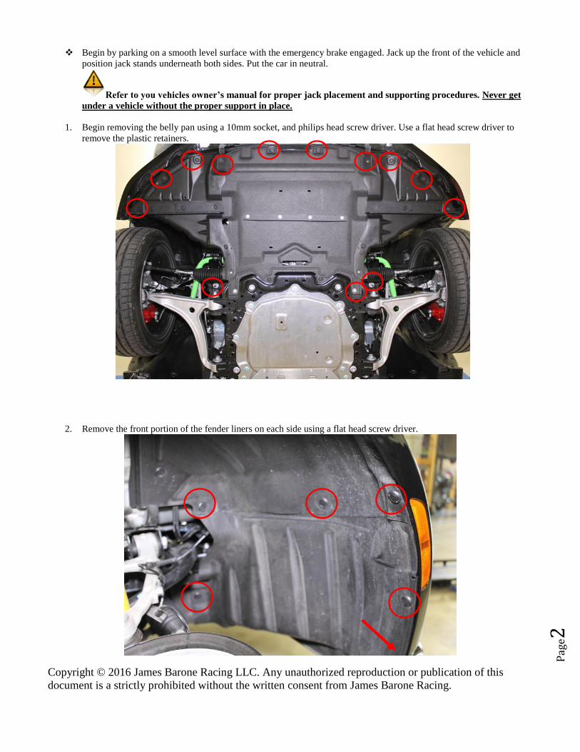
1. Begin removing the belly pan using a 10mm socket, and philips head screw driver. Use a flat head screw driver to
remove the plastic retainers.
2. Remove the front portion of the fender liners on each side using a flat head screw driver.
Copyright © 2016 James Barone Racing LLC. Any unauthorized reproduction or publication of this
document is a strictly prohibited without the written consent from James Barone Racing.
Pag
e3
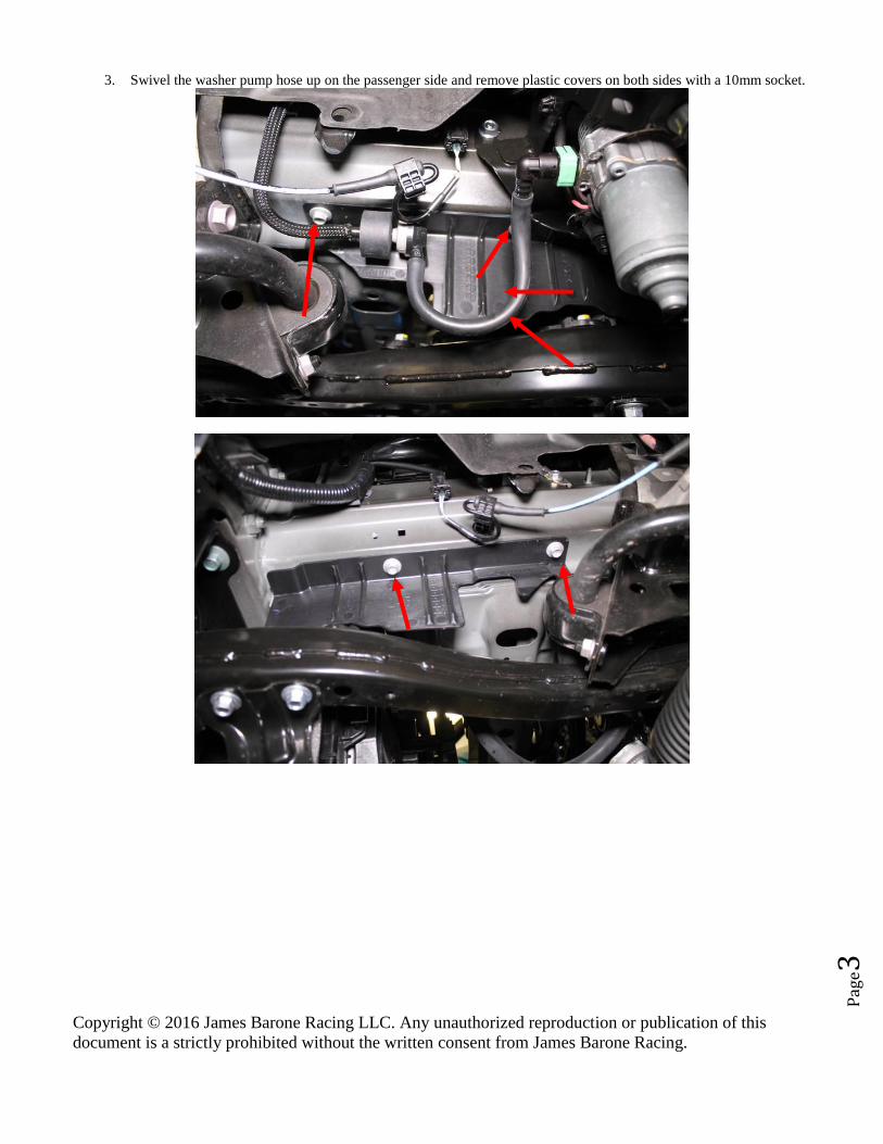
3. Swivel the washer pump hose up on the passenger side and remove plastic covers on both sides with a 10mm socket.
Copyright © 2016 James Barone Racing LLC. Any unauthorized reproduction or publication of this
document is a strictly prohibited without the written consent from James Barone Racing.
Pag
e4
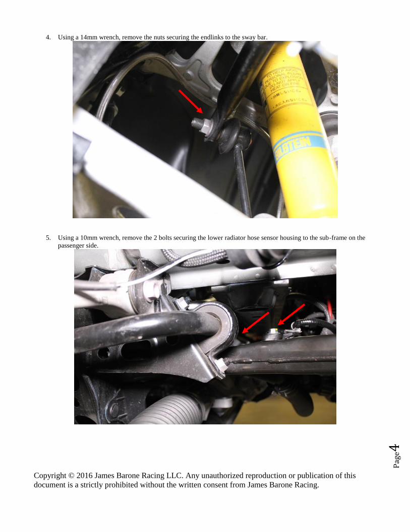
4. Using a 14mm wrench, remove the nuts securing the endlinks to the sway bar.
5. Using a 10mm wrench, remove the 2 bolts securing the lower radiator hose sensor housing to the sub-frame on the
passenger side.

Copyright © 2016 James Barone Racing LLC. Any unauthorized reproduction or publication of this
document is a strictly prohibited without the written consent from James Barone Racing.
Pag
e5
6. Remove the coolant sensor connector.
7. Unclip the coolant sensor wire from the sensor housing with a pair of needle nose pliers.
Copyright © 2016 James Barone Racing LLC. Any unauthorized reproduction or publication of this
document is a strictly prohibited without the written consent from James Barone Racing.
Pag
e6
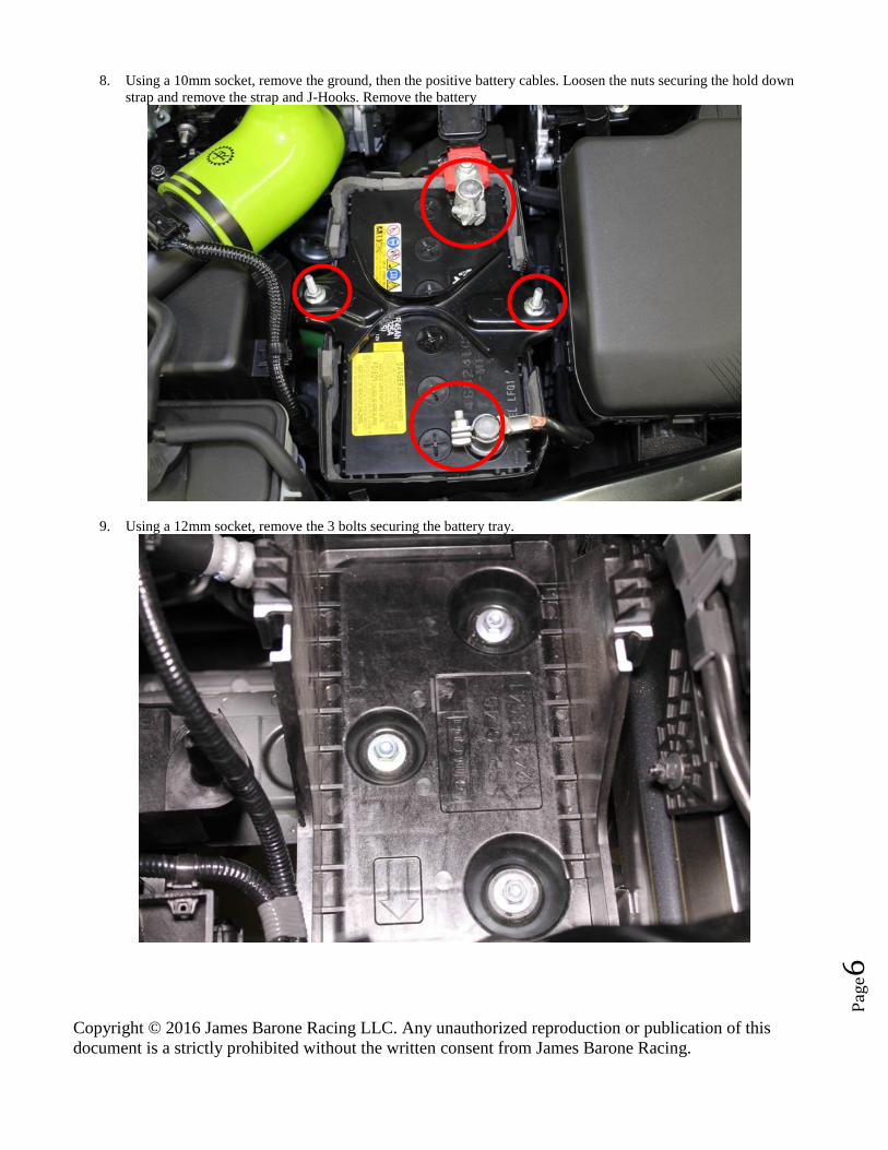
8. Using a 10mm socket, remove the ground, then the positive battery cables. Loosen the nuts securing the hold down
strap and remove the strap and J-Hooks. Remove the battery
9. Using a 12mm socket, remove the 3 bolts securing the battery tray.

Copyright © 2016 James Barone Racing LLC. Any unauthorized reproduction or publication of this
document is a strictly prohibited without the written consent from James Barone Racing.
Pag
e7
10. Using a 10mm socket, remove the two clamps securing the intake hose and remove from the air box and throttle body.
11. Using a 10mm socket remove the bolt securing the air box to the core support

Copyright © 2016 James Barone Racing LLC. Any unauthorized reproduction or publication of this
document is a strictly prohibited without the written consent from James Barone Racing.
Pag
e8
12. Remove the coolant over-flow hose at the cap and at the reservoir. Disconnect the MAF sensor and the fastener
securing the wire connector
13. Tug up on the entire air box assembly and remove from the vehicle.

Copyright © 2016 James Barone Racing LLC. Any unauthorized reproduction or publication of this
document is a strictly prohibited without the written consent from James Barone Racing.
Pag
e9
14. Spread the tabs on either side of the coolant reservoir, lift and remove from the vehicle.
15. Using a 12mm socket remove the air box support bracket.

Copyright © 2016 James Barone Racing LLC. Any unauthorized reproduction or publication of this
document is a strictly prohibited without the written consent from James Barone Racing.
Pag
e10
16. Disconnect the fan controller and the two clips securing the wire to the fan shroud.
17. Unclip and remove the wiring harness from beneath the core support.
Copyright © 2016 James Barone Racing LLC. Any unauthorized reproduction or publication of this
document is a strictly prohibited without the written consent from James Barone Racing.
Pag
e11
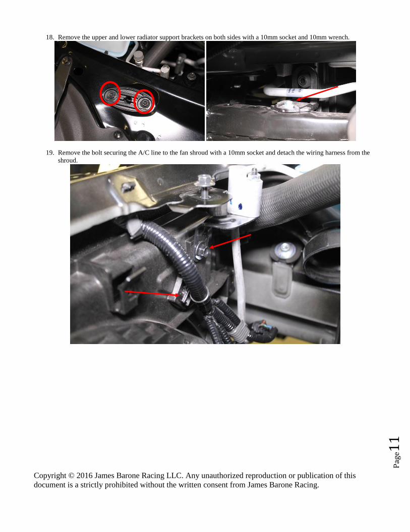
18. Remove the upper and lower radiator support brackets on both sides with a 10mm socket and 10mm wrench.
19. Remove the bolt securing the A/C line to the fan shroud with a 10mm socket and detach the wiring harness from the
shroud.

Copyright © 2016 James Barone Racing LLC. Any unauthorized reproduction or publication of this
document is a strictly prohibited without the written consent from James Barone Racing.
Pag
e12
20. Using a 10mm socket, remove the ground strap from the frame and disconnect the two connectors on the fan shroud.
21. Disconnect the wire from the A/C pressure sensor and the other at the shroud.

Copyright © 2016 James Barone Racing LLC. Any unauthorized reproduction or publication of this
document is a strictly prohibited without the written consent from James Barone Racing.
Pag
e13
22. Remove the connector from the shroud and ensure all wiring has been removed from the shroud.
23. Disconnect the lower radiator hose from the fan shroud.

Copyright © 2016 James Barone Racing LLC. Any unauthorized reproduction or publication of this
document is a strictly prohibited without the written consent from James Barone Racing.
Pag
e14
24. Carefully pull the fan shroud towards the rear of the car. Spread the tabs on either side of fan shroud, raise the shroud
out of the tabs and begin separating it from the radiator on the passenger side first.
25. Remove the fan shroud by separating it from the radiator on the passenger side, tilting it down and removing it from
the bottom of the vehicle. The next series of pictures illustrate the removal. This takes a bit of patience. Be careful not
to damage the fins of the radiator.

Copyright © 2016 James Barone Racing LLC. Any unauthorized reproduction or publication of this
document is a strictly prohibited without the written consent from James Barone Racing.
Pag
e15
26. Using a 14mm sock and 14mm wrench, remove the 2 nuts from both brackets securing the sway bar to the sub-frame.
Remove the brackets.

Copyright © 2016 James Barone Racing LLC. Any unauthorized reproduction or publication of this
document is a strictly prohibited without the written consent from James Barone Racing.
Pag
e16
27. Slide the sway bar forward so each arm clears the tie rod ends and rotate the bar so the arms are pointing towards the
ground.
28. Slide the bar towards the driver’s side; lift the passenger side arm over the sub-frame.

Copyright © 2016 James Barone Racing LLC. Any unauthorized reproduction or publication of this
document is a strictly prohibited without the written consent from James Barone Racing.
Pag
e17
29. Slide the bar towards the driver’s side and squeeze the passenger side bushing out from between the body and the sub-
frame as shown below.
30. Install your new JBR adjustable sway bar opposite of how the OEM was removed and get it into position.
31. Re-install and tighten the endlinks in the desired position to 36 ft/lbs. The hole towards the front of the car is the
stiffest and the hole towards the rear is the softest setting.
Hole location specs:
Towards the Front of the vehicle 490 lb/in 197%
Middle 415 lb/in 151%
Towards the Rear of the vehicle 355 lb/in 115%

Copyright © 2016 James Barone Racing LLC. Any unauthorized reproduction or publication of this
document is a strictly prohibited without the written consent from James Barone Racing.
Pag
e18
17. Use one of the provided grease packets for each bushing and slip the bushing over the sway bar and the brackets over
the bushings on to the studs and tighten the 14mm nuts to 30ft/lbs.
Use only synthetic grease when greasing the bushings. Grease should be applied at each oil change.
Carefully perform the steps in reverse in order to complete the installation of your front sway bar. Be cautious and
take your time when reinstalling the fan shroud. Enjoy!
Rear Sway bar Installation instructions
Begin by parking on a smooth level surface with the emergency brake engaged. Jack up the rear of the vehicle and
position jack stands underneath both sides. Put the car in neutral.
Refer to you vehicles owner’s manual for proper jack placement and supporting procedures. Never get
under a vehicle without the proper support in place.

Copyright © 2016 James Barone Racing LLC. Any unauthorized reproduction or publication of this
document is a strictly prohibited without the written consent from James Barone Racing.
Pag
e19
1. Using a 14mm socket, remove the two nuts securing the OEM sway bar to the endlinks. Using a 12mm socket remove
the two nuts securing the bushing brackets to the sub-frame and remove the brackets.
2. Slide the sway bar towards the driver’s side and remove it from the vehicle
3. Before installing your new JBR sway bar, apply one packet of grease to the inside of each bushing. Slide the pushing
over the end of the sway bar using the thin section with the adjustment holes to spread the bushing over the bar. Slide
the busing in to position.
4. Install the sway bar in the vehicle, secure the endlinks in the desired position, install the bushing brackets and reinstall
the nuts. Tighten the bushing bracket nuts to 15 ft/lbs and the endlink nuts to 36 ft/lbs
Hole location specs
Towards Front of the vehicle 235 lb/in 446%
Middle 175 lb/in 225%
Towards the Rear of the vehicle 140 lb/in 207%

Copyright © 2016 James Barone Racing LLC. Any unauthorized reproduction or publication of this
document is a strictly prohibited without the written consent from James Barone Racing.
Pag
e20
Congratulations!!
You’ve just completed the installation of your new
JBR front sway bar.