issn: 2454-1362, … · optical beam is known to be best for transmission over ......
TRANSCRIPT

Imperial Journal of Interdisciplinary Research (IJIR) Vol-2, Issue-10, 2016 ISSN: 2454-1362, http://www.onlinejournal.in
Imperial Journal of Interdisciplinary Research (IJIR) Page 1576
Implementing An Electrically Isolated
Power Supply For IGBT Gate Drivers
Using Ultrasonic Air Transducers
AlamAli1,&,Prof. Dr. Tahir Izhar
2
1,2Department of Electrical Engineering, University of Engineering and Technology, Main
GT Road, Lahore
Abstract— This paper primarily investigates the
method to build a regulated and electrically isolated
power supply which can deliver a constant voltage
and power of 15V-50mW with at least 30cm of
isolation distance between both circuits. This paper
proposes an innovative and a completely new method
to build an isolated power supply through acoustic
energy transfer mechanism where piezoelectric
transducers pr¬oduce and absorb ultrasound waves.
This energy transfer through ultrasound waves drive
the gate of an IGBT for usage in applications of
voltage source converters. Ultrasound transmission
system is adopted due to its low cost, complete
immunity from electrical and magnetic fields,
ruggedness in construction and less complexity in
building it.
Keywords—piezoelectric transducers, IGBTs, gate
drivers, acoustic energy transfer, flyback converter.
I. INTRODUCTION
A. Outline of research
This research paper proposes to build a regulated
and stable isolated power supply which can deliver
50𝑚𝑊/15𝑉 of power at an isolation distance of at
least 30𝑐𝑚. Knowledge about series and parallel
resonance, impedance matching, standing waves and
acoustic characteristics of isolation medium were
employed in getting the maximum power output.
Fluctuations in output voltage from the power supply
can be stabilized by a controlled DC-DC flyback
converter. In conclusion, we successfully constructed
a model for transferring 50𝑚𝑊/15𝑉 at an isolation
distance of about40𝑐𝑚 using air transducers, but the
efficiency achieved was only 8% due to huge power
losses in the isolation medium due to reflection and
attenuation of sound waves.
Fig 1: Circuit layout of IGBT gate driver.
B. Need for building an isolation medium for energy
transfer
Direct connection of a low voltage gate driving
circuit (±15𝑉) with the high voltage switching
circuit (±450𝐾𝑉) can produce many problems and
can negatively affect the operation of IGBT gate
driving. This can result in large power failures and
blackouts and swift replacement of converters can be
very costly [1].
Switching IGBTs at high voltage generates a
rapidly changing electric field. This 𝑑𝐸 𝑑𝑡 effect
generates huge electromagnetic interference (EMI),
high temperature discharges of corona and high
electric field at the converter leg causes ionization of
air in the conducting medium which causes
flashovers and degrades the performance of
converters [1, 2]. If the power supply of gate driver
circuit is not electrically isolated, the IGBT gate
circuit can get damaged due to huge electromagnetic
fluctuations leading to complete system failures.
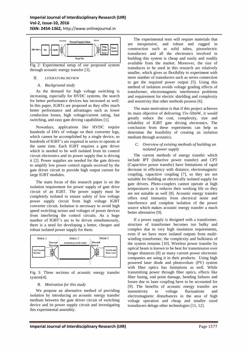
C. Experimental assembly
Experimental assembly of this system is shown in
figure 2 below. A sine wave is generated by the
waveform generator and is then amplified to 20𝑉𝑟𝑚𝑠
using an audio amplifier. This sinusoidal signal is
then applied to the transmitter transducer which
produces sound waves. These sound waves travel
through the isolated medium to the receiver
transducer which converts these sound waves back
into electrical energy. Air enclosed in a tube was
tested for proving this idea of building an isolated
power supply through acoustics.
Imperial Journal of Interdisciplinary Research (IJIR) Vol-2, Issue-10, 2016 ISSN: 2454-1362, http://www.onlinejournal.in
Imperial Journal of Interdisciplinary Research (IJIR) Page 1577
Fig 2: Experimental setup of our proposed system
through acoustic energy transfer [3].
II. LITERATURE REVIEW
A. Background study
As the demand for high voltage switching is
increasing, especially for HVDC systems, the search
for better performance devices has increased as well.
In this paper, IGBTs are proposed as they offer much
better performance and advantages such as lower
conduction losses, high voltage/current rating, fast
switching, and easy gate driving capabilities [1].
Nowadays, applications like HVDC require
hundreds of kWs of voltage on their converter legs,
which cannot be accomplished by a single device, so
hundreds of IGBT’s are required in series to operate at
the same time. Each IGBT requires a gate driver
which is needed to be well isolated from its control
circuit electronics and its power supply that is driving
it [2]. Power supplies are needed for the gate drivers
to amplify low power control signals received by the
gate driver circuit to provide high output current for
large IGBT modules.
The main focus of this research paper is on the
isolation requirement for power supply of gate drive
circuit of an IGBT. The power supply must be
completely isolated to ensure safety of low voltage
power supply circuit from high voltage IGBT
converter circuit. Isolation is necessary to avoid high
speed switching noises and voltages of power devices
from interfering the control circuits. As a huge
number of IGBT’s are to be driven simultaneously,
there is a need for developing a better, cheaper and
robust isolated power supply for them.
Fig 3: Three sections of acoustic energy transfer
system[4].
B. Motivation for this study
We propose an alternative method of providing
isolation by introducing an acoustic energy transfer
medium between the gate driver circuit of switching
device and its power supply circuit and investigating
this experimental assembly.
The experimental tests will require materials that
are inexpensive, and robust and rugged in
construction such as solid tubes, piezoelectric
transducers and all the electronics involved in
building this system is cheap and easily and readily
available from the market. Moreover, the size of
transduces to be used in this research are relatively
smaller, which gives us flexibility to experiment with
more number of transducers such as series connection
to get the required power output [5]. Using this
method of isolation avoids voltage grading effects of
transformer, electromagnetic interference problems
and requirement for electric shielding and complexity
and sensitivity that other methods possess [6].
The main motivation is that if this project achieves
its main objective of delivering 15v-50mW, it would
greatly reduce the cost, complexity, size and
reliability of IGBT gate driving electronics. The
conclusion from these experiments can help us
determine the feasibility of creating an isolation
medium through acoustics.
C. Overview of existing methods of building an
isolated power supply
The current methods of energy transfer which
include IPT (Inductive power transfer) and CPT
(Capacitive power transfer) have limitations of rapid
decrease in efficiency with distance, electromagnetic
coupling, capacitive coupling [7], so they are not
suitable for building an electrically isolated supply for
gate drivers. Photo-couplers cannot operate at high
temperatures as it reduces their working life so they
are not suitable as well [8]. Acoustic energy transfer
offers total immunity from electrical noise and
interference and complete isolation of the power
source which makes acoustic energy transfer a much
better alternative [9].
If a power supply is designed with a transformer,
structure of transformer becomes too bulky and
complex due to very high insulation requirements,
even if we have more isolated outputs from multi-
winding transformer, the complexity and bulkiness of
the system remains [10]. Wireless power transfer by
optical beam is known to be best for transmission over
longer distances [8] as many current power electronic
companies are using it in their products. Using high
powered laser diode and photovoltaic (PV) system
with fiber optics has limitations as well. While
transmitting power through fiber optics, effects like
fiber fusing, end point damage, bending failures and
losses due to laser coupling have to be accounted for
[9]. The benefits of acoustic energy transfer are
insensitivity to voltage fluctuations and
electromagnetic disturbances in the area of high
voltage operation and cheap and smaller sized
transducers deluge other technologies [11, 12].

Imperial Journal of Interdisciplinary Research (IJIR) Vol-2, Issue-10, 2016 ISSN: 2454-1362, http://www.onlinejournal.in
Imperial Journal of Interdisciplinary Research (IJIR) Page 1578
III. METHODOLOGY OF RESEARCH
A. Voltage and power calculation for
transmitter-receiver transducer pair
The methodology of research is getting the
required voltage and power for amplification of low
power control signal for driving the gate of an IGBT.
After getting the required air transducer and acoustic
material for medium, practical building of equipment
is carried out to get the maximum possible power
output.
Fig 4: Diagram for acoustic energy transfer [13].
B. Design of an audio amplifier circuit
The signal generator present in the Lab is capable of
giving 6𝑉𝑟𝑚𝑠 sinusoidal signal which is further
amplified using an audio amplifier to get the required
output voltage of 20𝑉𝑟𝑚𝑠 for driving the transmitter
transducer. The resistors needed for getting the
required gain are calculated:
𝐴𝑣 𝑔𝑎𝑖𝑛 = 1 +𝑅1
𝑅2
1 +12𝑘Ω
5𝑘Ω= 3.42
𝑅1 = 12𝑘Ω 𝑎𝑛𝑑 𝑅2 = 5𝑘Ω 𝑠𝑒𝑙𝑒𝑐𝑡𝑒𝑑
Fig 5: Audio amplifier circuit.
Fig 6: Circuit diagram of a non-inverting audio
amplifier.
C. Specifications of air transducers used
TCT40-16R/T were selected as the piezoelectric
air transducers as they were easily available in the
market and low cost. They had an external diameter of
16mm and the maximum input driving voltage
required for them was 20𝑉𝑟𝑚𝑠. The sound pressure
level created is 120𝑑𝐵 and attenuation of sound
pressure level is −10𝑑𝐵 and they work in a
bandwidth of 5𝑘𝐻𝑧. The capacitance of these
transducers is around2,500𝑝𝐹 and the frequency
required for generating ultrasounds is 40 ± 2 kHz.
The weigh 5𝑔 and their minimum sensitivity is
−60𝑑𝐵/𝑉/𝜇𝑏𝑎𝑟.
D. Conditions of all experiments performed
The isolation medium used was Perspex tube
having a diameter of 16𝑚𝑚 and air was used as a
material inside this medium. The voltage at
transmitter transducer was set as 20𝑉𝑟𝑚𝑠 and the
frequency of excitation used was 40𝑘𝐻𝑧. The
distance between transducers was kept at 37.2𝑐𝑚 for
experiment 1 and was varied in the range of 0𝑐𝑚 <𝑑𝑖𝑠𝑡𝑎𝑛𝑐𝑒 < 42.2𝑐𝑚 for experiment 2. For
experiment 3, the frequency of transmitter transducer
was changed in the range between 36𝑘𝐻𝑧 < 𝑓 <44𝑘𝐻𝑧 and was fixed at 40𝑘𝐻𝑧 for experiment 4 and
5.
Fig 7: Testing setup for measuring the output voltage
at receiver transducer.
IV. RESULTS WITH AIR TRANSDUCERS
A. Flow chart of experiments
The figure below shows the flowchart of
experiments conducted on these air transducers.
Fig 8: Flowchart of experiments performed on air
transducers.

Imperial Journal of Interdisciplinary Research (IJIR) Vol-2, Issue-10, 2016 ISSN: 2454-1362, http://www.onlinejournal.in
Imperial Journal of Interdisciplinary Research (IJIR) Page 1579
B. Sequence of experiments performed on
ultrasonic air transducers
In experiment 1, we got an output voltage of
6𝑚𝑊across a 5𝑘Ω resistor which was well below the
required output voltage of at least 50𝑚𝑊. So, we
performed experiment 2 where distance optimization
was done by finding the resonance point between both
the transducers and the optimal resonance distance
achieved was 𝑑 = 37.2𝑐𝑚.
Fig 9: Output voltage plotted versus distance.
Next, experiment 3 was performed where the
exact resonance frequency of transmitting transducer
was found by conducting a frequency scan in the
range of36𝑘𝐻𝑧 < 𝑓 < 44𝑘𝐻𝑧.
Fig 10: Plot of power output versus frequency.
An experiment 4 was conducted for finding the
value of load resistance which is required to match
with the source impedance for maximum power
transfer. It was conducted in the range of 50Ω −500𝑘Ω and the power output at each resistance value
was calculated.
Fig 11: Plot of power output versus load resistance for
impedance matching.
The required power output of 50𝑚𝑊 was still not
achieved as there are power losses in acoustic medium
to reflections and attenuations of sound waves [13]. In
experiment 5, two pairs of transducers were connected
in series combination to get an addition of power
output from each receiver transducer to get the
required power of 50𝑚𝑊 for building an isolated
supply.
Fig 11: Experimental setup for testing two pairs of
transducers which are connected in series.
Theoretical background tells that the impedance of
source to be matched adds up in series for receiver
transducers connected in series. This is proved using
the figure below such that the load resistance value in
series connected receivers should be 𝑅𝑝 ,𝑚𝑎𝑥 = 2 ×
5𝑘Ω = 10𝑘Ω.
Fig 12: Power output for series connected receivers
with different load resistances.
The power output of receiver transducers
connected in series combination adds up as shown in
below equation:
𝑃𝑡𝑜𝑡𝑎𝑙 ,𝑠𝑒𝑟𝑖𝑒𝑠 = 𝑃𝑜𝑢𝑡 ,1 + 𝑃𝑜𝑢𝑡 ,2
= 3.52 + 3.08 = 6.60𝑚𝑊 ≈ 6.23𝑚𝑊
Test No. 𝐏𝐨𝐮𝐭(𝐦𝐖)
𝑅𝑒𝑐𝑡𝑟𝑎𝑛𝑠 ,1 only 3.52
𝑅𝑒𝑐𝑡𝑟𝑎𝑛𝑠 ,2 only 3.08
𝑅𝑒𝑐𝑡𝑟𝑎𝑛𝑠 ,1 and 𝑅𝑒𝑐𝑡𝑟𝑎𝑛𝑠 ,2in series 6.23
Table 1: Addition of power output of
receivertransducer 1 and 2 connected in series.
V. CONCLUSIONS
The results of this experiment show that there is an
addition of power output from receiver transducers
connected in series. Using the best possible power
0
5
10
15
0 10 20 30 40
Vo
ut
d(cm)
Resonance
-2
0
2
4
6
8
36 38 40 42 44
Po
ut
(mW
)
f (kHz)
0.00
1.00
2.00
3.00
4.00
5.00
6.00
7.00
50 500 5000 50000 500000
Po
ut
(mW
)
R (Ω)
0
0.5
1
1.5
2
2.5
3
3.5
1000 11000 21000 31000 41000
Po
ut
(mW
)
R (Ω)

Imperial Journal of Interdisciplinary Research (IJIR) Vol-2, Issue-10, 2016 ISSN: 2454-1362, http://www.onlinejournal.in
Imperial Journal of Interdisciplinary Research (IJIR) Page 1580
output of transducers𝑃𝑏𝑒𝑠𝑡 from experiment 4 which is
6.54𝑚𝑊, the total power of the system is the
multiplication of this best power 𝑃𝑏𝑒𝑠𝑡 with the number
of series connected receiver transducers 𝑁.
𝑁 =𝑃𝑡𝑜𝑡𝑎𝑙 𝑝𝑜𝑤𝑒𝑟 𝑜𝑢𝑡𝑝𝑢𝑡
𝑃𝑜𝑢𝑡𝑝𝑢𝑡 𝑜𝑓 𝑜𝑛𝑒 𝑡𝑟𝑎𝑛𝑠𝑑𝑢𝑐𝑒𝑟
=50𝑚𝑊
6.54𝑚𝑊
𝑁 = 7.64 ≈ 8
This new technique of acoustic isolation can be a
game changer in the industry of voltage source
converters due to its superior quality, simple working
mechanism, cost effectiveness and immunity from
electromagnetic effects and easily available
components.
VI. ACKNOWLEDGMENTS
I will like to express my special appreciation and
gratitude to my thesis supervisor Prof. Dr. Tahir Izhar
whose support and guidance has enabled me to
achieve all the objectives of this research project.
VII. REFERENCES
[1] J.Lei and Y. Wang, “A power supply solution for
high-voltage IGBT drivers,” Proceedings of the
2012 IEEE 7th International Power Electronics
and Motion Control Conference (ECCE 2012),
vol. vol.4, pp. 2883-7, 2012.
[2] J.W. Baek, D. W. Yoo and H. G. Kim, “High
voltage switch using series-connected IGBTS
with simple auxiliary circuit,” Conference
Record of the 2000 IEEE Industry Applications
Conference. Thirty-Fifth Annual Meeting and
World Conference on Industrial Applications of
Electrical Energy, vol. vol4, pp. 2237-42, 2000.
[3] T. Zaid, S. Saat, Y. Yusop, and N. Jamal,
"Contactless energy transfer using acoustic
approach - A review," 2014 International
Conference on Computer, Communications and
Control Technology (I4CT), pp. 376-81, 2014.
[4] M. G. L. Roes, J. L. Duarte, M. A. M. Hendrix,
and E. A. Lomonova, “Acoustic energy transfer:
A review,” IEEE Trans. Ind. Electron., vol. 60,
pp. 242–248, Jan. 2013.
[5] R. Brocke and O. Beierl, "Influence of humidity
and pollution on the dielectric strength of
components used in Isolated LPS," in Lightning
Protection (ICLP), 2014 International
Conference, 2014, pp. 351-358.
[6] A. Kerkhoff, R. Curry, A. Donnelli, P. McGuyer,
and J. Streeter, “An Application of piezoelectric
wave converters for high voltage isolation and
power transmission,” Conference Record of the
Twenty-Third International Power Modulator
Symposium, pp. 225-8, 1998.
[7] A. Ganguly, "Solid State," in Fundamentals of
physical chemistry , 2nd ed. India: Pearson
Education , 2011,ch.11,pp.11.41.
[8] A. Sahai and D. Graham, “Optical wireless
power transmission at long wavelengths,” 2011
International Conference on Space Optical
Systems and Applications (ICSOS 2011), pp.
164-70, 2011.
[9] M. C. T. M. Ari, “Electrical Power Over Fiber
Optics,” International Journal on “Technical and
Physical Problems of Engineering,” vol. 2, pp.
85-91, 2010.
[10] F. Wanmin, L. Zhengyu, X. Linghui and J.
Gaoxian, “A novel high-voltage isolation power
supply for multiple devices driving,” Conference
Proceedings IPEMC 2004. The 4th International
Power Electronics and Motion Control
Conference (IEEE Cat. No. 04EX677), vol. Vol.
1, pp. 111-14, 2004.
[11] L. Huidong, T. Chuan, and Z. D. Deng, “Energy
harvesting from low frequency applications
using piezoelectric materials,” Applied Physics
Reviews, vol. 1, p. 041301 (20), 2014.
[12] H. F. Leung, B. J. Willis, and A. P. Hu,
“Wireless electric power transfer based on
Acoustic Energy through conductive media,”
Proceedings of the 2014 9th IEEE Conference on
Industrial Electronics and Applications, ICIEA
2014, pp. 1555-1560, 2014.
[13] Y. C. Shu and I. C. Lien, “Efficiency of energy
conversion for a piezoelectric power harvesting
system,” Journal of Micromechanics and
Microengineering, vol. 16, pp. 2429-38, 2006.