issn: 2454-1362, implementation of high step-up dc- dc ... · 2016-10-13 · implementation of high...
TRANSCRIPT

Imperial Journal of Interdisciplinary Research (IJIR) Vol-2, Issue-11, 2016 ISSN: 2454-1362, http://www.onlinejournal.in
Imperial Journal of Interdisciplinary Research (IJIR) Page 800
Implementation of High Step-Up DC-DC Converter With Fuzzy Logic
Controller based Solar PowerOptimizer
P. Alexander1 & P. Suneel Raju2 1M-tech Student Scholar, 2Associate Professor
1,2Department of Electrical & Electronics Engineering, RVR & JC College of Engineering , Guntur, Andhra Pradesh, India.
Abstract-Solar Power Optimizer for DC Distribution System is composed of a high step-up solar power optimizer(SPO), efficiently harvests maximum energy from a photovoltaic (PV) panel outputs energy to a dc-micro grid. Its structure integrates coupled inductor and switched capacitor technologies to realize high step-up voltage gain. The leakage inductance energy of the coupled inductor can be recycled to reduce voltage stress and power losses. A low voltage rating and low-conduction resistance switch improves system efficiency by employing the incremental conductance method for the maximum power point tracking (MPPT) algorithm. Because of its high tracking accuracy, the method is widely used in the energy harvesting of PV systems. The power reduction caused by the shadow effect on PV panels is an inevitable problem in a centralized PV system.This paper proposes an artificial intelligence-based fuzzy logiccontrol scheme for the MPP tracking of a solar photovoltaic system under variable temperature and insolation conditions. The method uses a fuzzy logic controller (FLC) applied to a dc–dc converter device. The different steps of the design of this controller are presented together with its simulation. Simulation results are compared with those obtained by the perturbation and observation controller. The results show that the FLC exhibits a muchbetter behavior. Index Terms—High step-up voltage gain, maximum power pointtracking (MPPT),Solar Energy, Photovoltaic system, Fuzzy Logic Control.
I.INTRODUCTION The Solar Power Optimizer for DC Distribution System,a development of photovoltaic (PV) power generation system,which uses a renewable resource, has been extensively used in emergency facilities and in generating electricity for mass use[1]. A conventional PV generation system is either a single- or a multi string PV array that is
connected to one or several central PV inverters. Numerous series-connected PV modules are connected in the PV array to achieve the DC link voltage that is high enough to be connected to electricity through the DCAC inverter[2]. Though, reduction in power caused by the shadow effect is an unavoidablenature in a centralized PV system. The use of a micro inverter or ac module has recently been proposed for individual PV panels. Although this discrete PV power generation solution may partially eliminate the shadow problem, a micro inverter structure constrains the system energy’s harvesting efficiency and entails high costs [3]. The SPO attempts to improve the use of distributed renewable resources and lower system cost. It may also potentially improve the efficiency of PV systems, has an anti-shadow effect, and can monitor the status of PV modules. Moreover, the dc-grid voltage is regulated by bidirectional inverter and battery tank. [4-5] In case of low-loading condition, the redundant energy will store into battery or through bidirectional inverter to ac grid. A solar power optimizer (SPO) was developed as an alternative to maximize energy harvest from each individual PV module. The presented tracking algorithm shows bettersteady state and dynamical performance than traditional P&O. The implementation of fuzzy logic controller based on the change of power and change of power with respect to change of voltage is studied in [6], fuzzy determines the size of the perturbed voltage. The performance of fuzzy logic with various membership functions (MFs) is tested to optimize the MPPT. Fuzzy logic can facilitate the tracking of maximum power faster and minimize the voltage variation. A novel intelligent fuzzy logic controller for MPPT in grid-connected photovoltaic systems based on boost converter and single phase grid-connected inverter is introduced in [7]. This is simple to be implemented on MCU chip and needs no memory space to save fuzzy rules, and that optimizing factor in the fuzzy inference equation can adjust fuzzy rules on-line
Imperial Journal of Interdisciplinary Research (IJIR) Vol-2, Issue-11, 2016 ISSN: 2454-1362, http://www.onlinejournal.in
Imperial Journal of Interdisciplinary Research (IJIR) Page 801
automatically toimprove system control effect, which provides the system with an intelligent characteristic. An intelligent control method for MPPT of a photovoltaic system under variable temperature and insolation conditions which uses a fuzzy logic controller applied to a DC-DC converter device is proposed in [8-9]. Results of this simulation are compared to those obtained by the perturbation and observation controller. A fuzzy logic control (FLC) is proposed in [10] to control MPPT for a photovoltaic (PV) system; this technique uses the fuzzy logic control to specify the size of incremental current in the current command of MPPT. This paper presents a Maximum Power Point Tracker (MPPT) using Fuzzy Logic for a PV system. The work focused on the well known Perturb and Observe (P&O) algorithm and compared to a designed Fuzzy Logic Controller (FLC). A simulation work dealing with MPPT controller, a DC/DC Ćuk converter feeding a load is achieved. The results will show the validity of the proposed fuzzy logic MPPT in the PV system [11-13].
Fig. 1. Configuration of the proposed SPO.
The proposed SPO is shown in Fig. 1; its configuration is based on a high step-up dc–dc converter with an MPPT control circuit. The converter includes a floating active switch S and a coupled inductor T1 with primary winding N1, which is similar to the input inductor of a conventional boost converter capacitor C1, and diode D1 recycle leakage inductance energy from N1. Secondary winding N2 is connected to another pair of capacitors, C2 and C3, and to diodes D2 and D3. Rectifier diode D4 connects to output capacitor Co and load R. The duty ratio is modulated by the MPPT algorithm, which uses the perturb and observer method that is employed in the proposed SPO. It detects PV module voltage Vpv and current Ipv to determine the increase and decrease in the duty cycle of the dc converter. Therefore, the MPP can be obtained by comparing instantaneous
conductance I/V and incremental conductance dI/dV. The proposed converter has the following features: 1) its voltage conversion ratio is efficiently increased by using the switched capacitor and coupled inductor techniques; 2) The leakage inductance energy of the coupled inductor can be recycled to increase efficiency, and the voltage spike on the active switch is restrained; 3) The floating active switch isolates the PV panel’s energy during non-operating conditions, thereby preventing any potential electric hazard to humans or facilities. The MPPT control algorithm exhibits high-tracking efficiency;
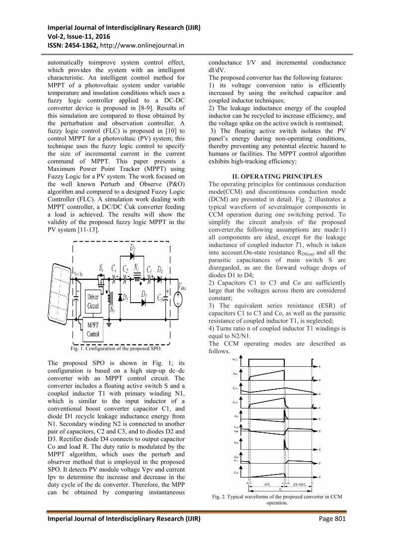
II. OPERATING PRINCIPLES The operating principles for continuous conduction mode(CCM) and discontinuous conduction mode (DCM) are presented in detail. Fig. 2 illustrates a typical waveform of severalmajor components in CCM operation during one switching period. To simplify the circuit analysis of the proposed converter,the following assumptions are made:1) all components are ideal, except for the leakage inductance of coupled inductor T1, which is taken into account.On-state resistance RDS(on) and all the parasitic capacitances of main switch S are disregarded, as are the forward voltage drops of diodes D1 to D4; 2) Capacitors C1 to C3 and Co are sufficiently large that the voltages across them are considered constant; 3) The equivalent series resistance (ESR) of capacitors C1 to C3 and Co, as well as the parasitic resistance of coupled inductor T1, is neglected; 4) Turns ratio n of coupled inductor T1 windings is equal to N2/N1. The CCM operating modes are described as follows.
Fig. 2. Typical waveforms of the proposed converter in CCM
operation.

Imperial Journal of Interdisciplinary Research (IJIR) Vol-2, Issue-11, 2016 ISSN: 2454-1362, http://www.onlinejournal.in
Imperial Journal of Interdisciplinary Research (IJIR) Page 802
A. CCM OPERATION The CCM operating modes are described as follows. Mode I [t0 , t1 ]:During this interval, switch S and diodes D2 and D3 are conducted; diodes D1 and D4 are turned OFF. The current flow path is shown in Fig.3(a). Magnetizing inductor Lm continues to release energy to capacitors C2 and C3 through secondary windingN2 of coupled inductor T1. Leakage inductance Lk 1 denotes the stored energy from source energy Vin. The energy that is stored in capacitor Co is constantly discharged to load R. This mode ends when increasing iLk1 is equal to decreasing iLm at t = t1.
Mode II [t1 , t2 ]:During this interval, switch S and diode D4 are conducted. Source energy Vin is serially connected to C1, C2 , and C3 , and secondary winding N2 ; Lk2 discharges the energy that is stored in charge output capacitor Co and loads R. Meanwhile, magnetizing inductor Lm also receives energy from Vin . The current flow path is shown in Fig.3(b). This mode ends when switch S is turned OFF at t = t2.
Mode III [t2, t3]:During this transition interval, switch S and diodes D2 and D3 are turned OFF, and diodes D1 and D4 are conducted. The current flow path is shown in Fig.3(c). The energy stored in leakage inductance Lk 1 instantly flows through the diode D1 to charge capacitor C1. The energy is released to magnetizing inductor Lm through coupled inductor T1, which is serially connected to C1, C2, and C3, and secondary winding N2; Lk2 discharges the energy that is stored in charge output capacitor Co and loads R. This mode ends when decreasing iLk1 is equal to increasing iLm at t = t3.
Mode IV [t3, t4 ]:During this interval, switch S and diode D4 are turned OFF, and diodes D1,D2 , and D3 are conducted. The current flow path is shown in Fig.3 (d). Leakage inductance Lk 1 continues to release energy to charge capacitor C1 through diode D1. Magnetizing inductor Lm through coupled inductor T1 transfers energy to capacitors C2 and C3. The energy that is stored in capacitor CO is constantly discharged to load R. This mode ends when decreasing iLk1 is zero at t = t4.
Mode V [t4, t5]:During this interval, diodes D2 and D3 are conducted. The current flow path is shown in Fig.3 (e). Magnetizing inductor Lm constantly transfers energy to secondary winding N2, and charges capacitors C2 and C3. The energy that is stored in capacitor CO is constantly discharged to load R. This mode ends when switch S is turned ON at the beginning of the next switching period.
Fig. 3. Current flow path in five operating modes
during one switching period in CCM operation: (a) Mode I, (b) Mode II, (c) Mode III, (d) Mode IV,
and(e) Mode V. B. DCM OPERATION Mode I [t0 , t1 ]:During this interval, switch S and D4 are conducted, and diodes D1,D2 , and D3 are turned OFF. The current flowpath is shown in Fig.5(a).Magnetizing inductorLm with leakage

Imperial Journal of Interdisciplinary Research (IJIR) Vol-2, Issue-11, 2016 ISSN: 2454-1362, http://www.onlinejournal.in
Imperial Journal of Interdisciplinary Research (IJIR) Page 803
inductance Lk 1 stores energy from source energy Vin . Meanwhile, source energy Vin is also serially connected to capacitors C1, C2 , and C3 , and secondary winding N2 to charge capacitor Co and load R. This mode ends when switch S is turned OFF at t = t1.
Fig. 4. Typical waveforms of the proposed converter during
DCM operation. Mode II [t1, t2]:During this transition interval, switch S and diodes D2 and D3 are turned OFF, and diodes D1 and D4 are conducted. The current flow path is shown in Fig. 5(b). The energy stored in leakage inductance Lk 1 instantly flows through the diodeD1 to charge capacitor C1 ; this energy is also released to magnetizing inductor Lm through the coupled inductor T1 series that is connected to C1, C2 , and C3 , secondary winding N2 , and Lk2 to charge output capacitor Co and load R. This mode ends when decreasing iD4 is zero at t = t2.
Mode III [t2 , t3 ]:During this transition interval, switch S and diode D4 are turned OFF, and diodes D1,D2 , and D3 are conducted. The current flow path is shown in Fig. 5(c). Leakage inductance Lk 1 continues to release energy to charge capacitor C1 through diode D1. Magnetizing inductor Lm transfers energy to capacitors C2 and C3 through coupled inductor T1. The energy stored in capacitor Co is constantly discharged to load R. This mode ends when decreasing iLk1 is zero at t = t3.
Mode IV [t3,t4]: During this interval, switch S, diodes D1 and D4 are turned OFF, and diodes D2 and D3 are conducted. The current flow path is shown in Fig. 5(d).Magnetizing inductor Lm constantly transfers energy to secondary winding N2 and charges capacitors C2 and C3. The energy that is stored in capacitor Co is constantly discharged to load R. This mode endswhen decreasing iLm is zero at t = t4.
Mode V [t4,t5]:During this interval, the switch and all the diodes are turned OFF. The current flow path is shown in Fig. 5(e). The energy that is stored in capacitor CO is constantlydischarged to load R. This mode ends when switch S is turned ON at the beginning of the next switching period.

Imperial Journal of Interdisciplinary Research (IJIR) Vol-2, Issue-11, 2016 ISSN: 2454-1362, http://www.onlinejournal.in
Imperial Journal of Interdisciplinary Research (IJIR) Page 804
Fig. 5. Current flow path in five operating modes during one
switching periodin DCM operation: (a) Mode I, (b) Mode II, (c) Mode III, (d) Mode IV, and(e) Mode V.
III.FUZZY LOGIC CONTROL
L. A. Zadeh presented the first paper on fuzzy set theory in 1965. Since then, a new language was developed to describe the fuzzy properties of reality, which are very difficult and sometime even impossible to be described using conventional methods. Fuzzy set theory has been widely used in the control area with some application to power system [5]. A simple fuzzy logic control is built up by a group of rules based on the human knowledge of system behavior. Matlab/Simulink simulation model is built to study the dynamic behavior of converter. Furthermore, design of fuzzy logic controller can provide desirable both small signal and large signal dynamic performance at same time, which is not possible with linear control technique. Thus, fuzzy logic controller has been potential ability to improve the robustness of compensator.
Fig. 6. Fuzzy logic Control of the PFC BL-CSC converter
feeding BLDC Motor Drive.
The basic scheme of a fuzzy logic controller is shown in Fig 8 and consists of four principal components such as: a fuzzyfication interface, which converts input data into suitable linguistic values; a knowledge base, which consists of a data base with the necessary linguistic definitions and the control rule set; a decision-making logic which, simulating a human decision process, infer the fuzzy control action from the knowledge of the control rules and linguistic variable definitions; a de-fuzzification interface which yields non fuzzy control action from an inferred fuzzy control action [10].
Fig.7.Block diagram of the Fuzzy Logic Controller (FLC)for
proposed converter.
Fig.8. Membership functions for error.

Imperial Journal of Interdisciplinary Research (IJIR) Vol-2, Issue-11, 2016 ISSN: 2454-1362, http://www.onlinejournal.in
Imperial Journal of Interdisciplinary Research (IJIR) Page 805
Fig.9. Membership functions for change_in_error.
Fig.10. Membership functions for Output.
Fuzzy rules for error and change of error.
IV.MATLAB/SIMULATION RESULTS
Fig.11.Matlab/Simulink model of proposed SPO with open loop
system.
Fig.12.Photovoltaic voltage.
Fig.13.output current of the proposed converter with open loop
system.
Fig.14.output Voltage of the proposed converter with open loop
system.
Fig.15.output power of the proposed converter with open loop
system.
Fig.16.Matlab/Simulink model of proposed SPO with Closed
loop system and fuzzy logic controller.

Imperial Journal of Interdisciplinary Research (IJIR) Vol-2, Issue-11, 2016 ISSN: 2454-1362, http://www.onlinejournal.in
Imperial Journal of Interdisciplinary Research (IJIR) Page 806
Fig.17.output current of the proposed converter with closed loop
system and fuzzy logic controller.
Fig.18.output voltage of the proposed converter with closed loop
system and fuzzy logic controller.
Fig.19.Output power of the proposed converter with closed loop
system and fuzzy logic controller.
V. CONCLUSION The high step-up SPO uses the coupled inductor with an appropriate turn’s ratio design and switched-capacitor technologyto achieve a high-voltage gain that is 20 times higher than the input voltage.The inputs of Photovoltaic (PV) panel are solar temperature and solar irradiance which converts the solar power into PV voltage and PV current which is fetch as input to MPPT. The MPPT control techniques are done with both PI and FUZZY and is designed in SIMULINK. The voltage gain and efficiency is then measured using display and then calculated theoretically. Both the results are then compared and the control technique enhancing maximum efficiency is implemented.
REFERENCES [1].W. Yu, J.-S. Lai, H. Qian, and C. Hutchens, “High-efficiency MOSFET inverter with H6-type configuration for photovoltaic non isolated ac-module applications,” IEEE Trans. Power Electron., vol. 26, no. 4, pp. 1253–1260, Apr. 2011. [2].L. Gao, R. A. Dougal, S. Liu, and A. P. Iotova, “Parallel-connected solarPV system to address partial and rapidly fluctuating shadow conditions,” IEEE Trans. Ind. Electron., vol. 56, no. 5, pp. 1548–1556, May 2009. [3].R. Gules, J. De Pellegrin Pacheco, H. L. Hey, and J. Imhoff, “A maximum power point tracking system with parallel connection for PV stand-alone applications,” IEEE Trans. Ind. Electron., vol. 55, no. 7, pp. 2674–2683, Jul. 2008.
[4].B. Liu, S. Duan, and T. Cai, “Photovoltaic dc-building-module-based BIPV system: Concept and design considerations,” IEEE Trans. Power Electron., vol. 26, no. 5, pp. 1418–1429, May 2011. [5].W. Xiao, N. Ozog, and W. G. Dunford, “Topology study of photovoltaic interface for maximum power point tracking,” IEEE Trans. Ind. Electron., vol. 54, no. 3, pp. 1696–1704, Jun. 2007. [6].Afzal, A., Mohibullah, M., and Sharma, V.K., 2010. Optimal hybrid renewable energy systems for energy security: a comparative study. International Journal of Sustainable Energy, 29, 48–58. [7].Ansari, F., et al., 2008. Modeling and simulation of optimal power tracking of multiple modules paralleled SPV system. Journal of Engineering & Technology Education, 2 (2), 31–35. [8].Ansari, F., et al., 2008. Solar photo voltaic power conversion using maximum power point tracking and design. In: Renewable energy Asia – an international conference 2008 & 4th SEE forum Meeting, 11–13 December 2008. Delhi: IIT. [9].Ansari, F., et al., 2009. Control MPPT for photovoltaic systems using advanced algorithm EPP. In: Third international conference on power systems, 27–29 December 2009. Kharagpur: IIT. [10].Ansari, F., et al., 2010. Automatic maximum power point tracker for solar PV modules using dSPACE software. International Journal of Sustainable Energy, 29 (3), 151–163. [11].Boehinger, A.F., 1968. Self-adaptive DC converter for solar spacecraft power supply. IEEE Transaction on Aerospace and Electronic Systems, AES-4 (1), 102–111. [12].Gottschalg, R., et al., 1997. Comparison of different methods for the parameter determination of the solar cell’s double exponential equation. In: 14th European photovoltaic science and engineering conference (PVSEC), Barcelona, Spain. [13].Hohm, D.P. and Ropp, M.E., 2000. Comparative study of maximum power point tracking algorithms using an experimental, programmable, maximum power point tracking test bed. In: 28th IEE 2000. Photovoltaic Specialist Conference, Anchorage, AK, 1699–1702.