is now part of - fairchild semiconductor questions or comments ... provide single supply mosfet gate...
TRANSCRIPT

To learn more about ON Semiconductor, please visit our website at www.onsemi.com
Is Now Part of
ON Semiconductor and the ON Semiconductor logo are trademarks of Semiconductor Components Industries, LLC dba ON Semiconductor or its subsidiaries in the United States and/or other countries. ON Semiconductor owns the rights to a number of patents, trademarks, copyrights, trade secrets, and other intellectual property. A listing of ON Semiconductor’s product/patent coverage may be accessed at www.onsemi.com/site/pdf/Patent-Marking.pdf. ON Semiconductor reserves the right to make changes without further notice to any products herein. ON Semiconductor makes no warranty, representation or guarantee regarding the suitability of its products for any particular purpose, nor does ON Semiconductor assume any liability arising out of the application or use of any product or circuit, and specifically disclaims any and all liability, including without limitation special, consequential or incidental damages. Buyer is responsible for its products and applications using ON Semiconductor products, including compliance with all laws, regulations and safety requirements or standards, regardless of any support or applications information provided by ON Semiconductor. “Typical” parameters which may be provided in ON Semiconductor data sheets and/or specifications can and do vary in different applications and actual performance may vary over time. All operating parameters, including “Typicals” must be validated for each customer application by customer’s technical experts. ON Semiconductor does not convey any license under its patent rights nor the rights of others. ON Semiconductor products are not designed, intended, or authorized for use as a critical component in life support systems or any FDA Class 3 medical devices or medical devices with a same or similar classification in a foreign jurisdiction or any devices intended for implantation in the human body. Should Buyer purchase or use ON Semiconductor products for any such unintended or unauthorized application, Buyer shall indemnify and hold ON Semiconductor and its officers, employees, subsidiaries, affiliates, and distributors harmless against all claims, costs, damages, and expenses, and reasonable attorney fees arising out of, directly or indirectly, any claim of personal injury or death associated with such unintended or unauthorized use, even if such claim alleges that ON Semiconductor was negligent regarding the design or manufacture of the part. ON Semiconductor is an Equal Opportunity/Affirmative Action Employer. This literature is subject to all applicable copyright laws and is not for resale in any manner.

© 2014 Fairchild Semiconductor Corporation FEBSPM7_M02MTCA • Rev. 1.0
User Guide for
FEBSPM7_M02MTCA
Evaluation Board
Motion SPM®
7 Series
Featured Fairchild Products:
FSB70250
FSB70450
FSB70550
FSB70325
FSB70625
Direct questions or comments about this evaluation board to:
“Worldwide Direct Support”
Fairchild Semiconductor.com
© 2014 Fairchild Semiconductor Corporation 2 FEBSPM7_M02MTCA • Rev. 1.0
Table of Contents
1. Introduction ............................................................................................................................... 3
1.1. Description ....................................................................................................................... 3 1.2. Features ............................................................................................................................ 3
2. Evaluation Board Specifications ............................................................................................... 4
3. Photographs............................................................................................................................... 5
4. Printed Circuit Board ................................................................................................................ 6
4.1. External Connection ......................................................................................................... 8
5. Schematic .................................................................................................................................. 9
5.1. Circuit Description ......................................................................................................... 10
6. Thermal performance .............................................................................................................. 11
6.1. Thermal Photo (without Heatsink) ................................................................................. 11 6.2. Thermal Photos (with a Heatsink of 6.5 K/W Mounted on Bottom Side) ..................... 12
7. Bill of Materials ...................................................................................................................... 13
8. Revision History ..................................................................................................................... 14
© 2014 Fairchild Semiconductor Corporation 3 FEBSPM7_M02MTCA • Rev. 1.0
1. Introduction
This user guide supports the evaluation kit for the Motion SPM®7 Series. It should be
used in conjunction with the Motion SPM®7 datasheets as well as Fairchild’s application
notes and technical support team. Please visit Fairchild’s website at
www.fairchildsemi.com.
1.1. Description
Fairchild’s Motion SPM®7 Series provides efficient motor control for energy restricted
small power inverter driven application when space is constrained, such as circulation
pump, compact fan.
Motion SPM®7 series integrates six fast-recovery MOSFETs (FRFET®) and one three-
phase High Voltage ICs (HVIC). Motion SPM®7 series reduces board space by utilizing
an ultra-compact 12.9 mm x 12.9 mm package and by incorporating built-in HVIC that
provide single supply MOSFET gate driving capability. The Motion SPM®7 series offers
designers high reliability with integrated Under-Voltage Lockout (UVLO), Thermal
Sensing Function (VTS) and Over-Current Protection (OCP).
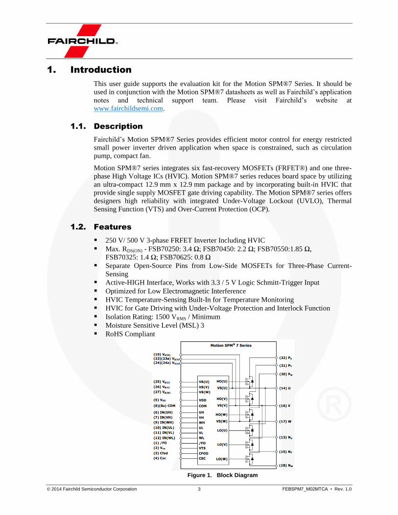
1.2. Features
250 V/ 500 V 3-phase FRFET Inverter Including HVIC
Max. RDS(ON) - FSB70250: 3.4 Ω; FSB70450: 2.2 Ω; FSB70550:1.85 Ω,
FSB70325: 1.4 Ω; FSB70625: 0.8 Ω
Separate Open-Source Pins from Low-Side MOSFETs for Three-Phase Current-
Sensing
Active-HIGH Interface, Works with 3.3 / 5 V Logic Schmitt-Trigger Input
Optimized for Low Electromagnetic Interference
HVIC Temperature-Sensing Built-In for Temperature Monitoring
HVIC for Gate Driving with Under-Voltage Protection and Interlock Function
Isolation Rating: 1500 VRMS / Minimum
Moisture Sensitive Level (MSL) 3
RoHS Compliant
Figure 1. Block Diagram

© 2014 Fairchild Semiconductor Corporation 4 FEBSPM7_M02MTCA • Rev. 1.0
2. Evaluation Board Specifications
All data for this table was measured at an ambient temperature of 25°C.
Table 1. Summary of Features and Performance
Description Symbol Min. Typ. Max. Unit
Positive DC Bus Link Input V_dcb
(1) 120 375
V V_dcb
(2) 120 250
DC voltage Output V15 15 V
Logic 1 input VIH 2.4 V
Logic 0 input VIL 0.8 V
Fault Output /Fo 0 15 V
Analog Output Range Vsig_a(3)
0 5 V
Bus Voltage Sensing Vs_dcb 8.4 mV/V
Phase Current Sensing 47 mV/A
Dead Time tdead 500 ns
PWM Switching Frequency tPWM 15 kHz
Temperature Sensing Vts (4)
19 mV/°C
Notes:
1. FSB70250, FSB70450 and FSB70550. 2. FSB70325 and FSB70625. 3. Analog Outputs include: three phase current sensing is_U, is_V, is_W; Temperature Sensing
Vts, Bus Voltage Sensing Vs_dcb. 4. Temperature of SPM®7 Module, for more detail, please refer to the corresponding SPM®7
data sheet.
© 2014 Fairchild Semiconductor Corporation 5 FEBSPM7_M02MTCA • Rev. 1.0
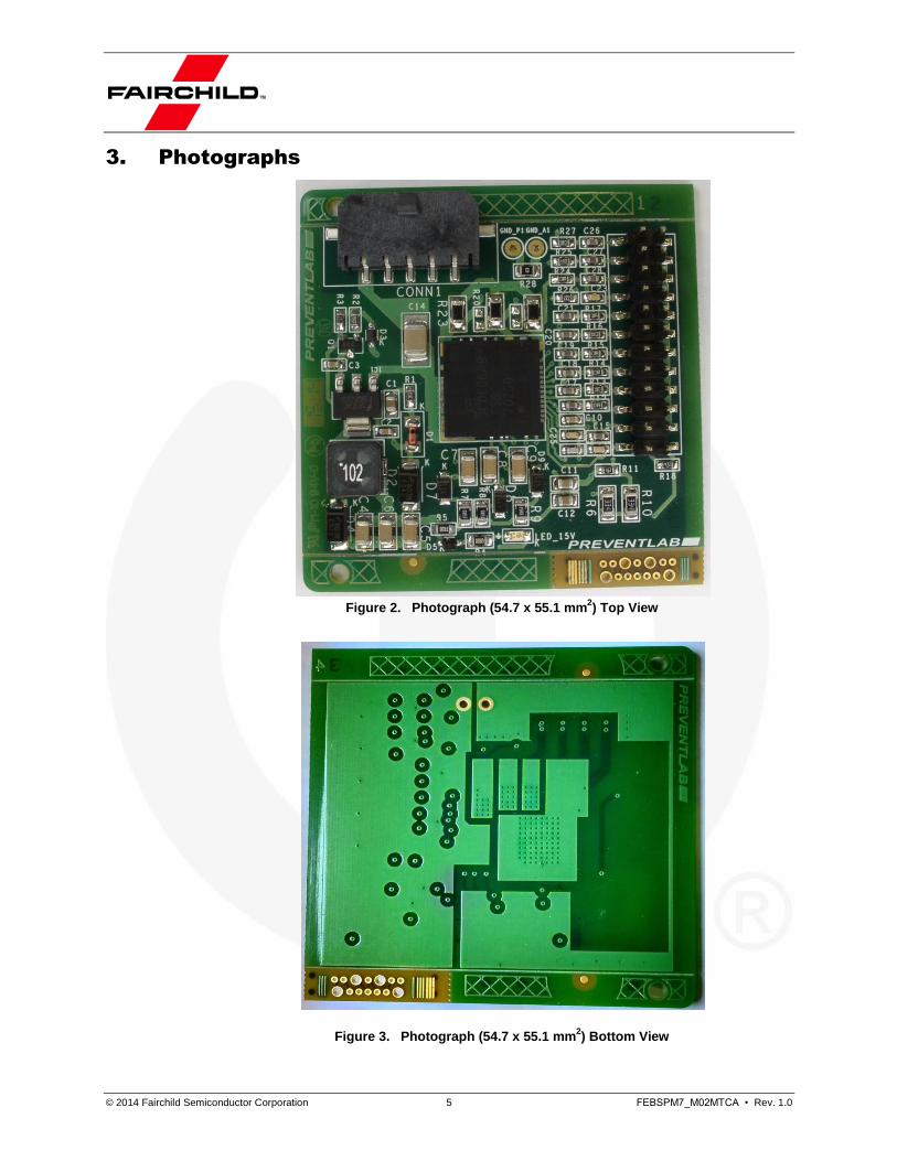
3. Photographs
Figure 2. Photograph (54.7 x 55.1 mm
2) Top View
Figure 3. Photograph (54.7 x 55.1 mm
2) Bottom View

© 2014 Fairchild Semiconductor Corporation 6 FEBSPM7_M02MTCA • Rev. 1.0
4. Printed Circuit Board
Figure 4. Top Side
Figure 5. Inner layer 1
© 2014 Fairchild Semiconductor Corporation 7 FEBSPM7_M02MTCA • Rev. 1.0
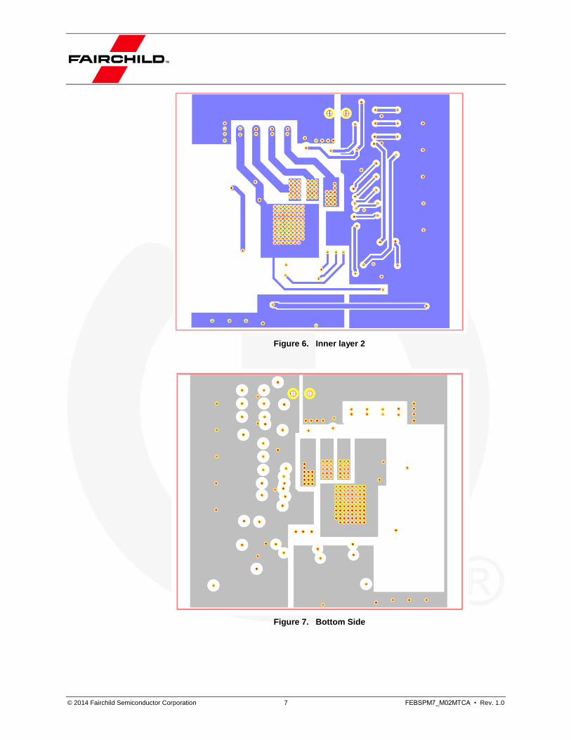
Figure 6. Inner layer 2
Figure 7. Bottom Side

© 2014 Fairchild Semiconductor Corporation 8 FEBSPM7_M02MTCA • Rev. 1.0
4.1. External Connection
Figure 8. CONN1 and J1 Connector Physical View
Table 2. Connector J1:
Pin# Signal Name Description
1 15 V +15 V Out of Internal Power Supply, Supply Max. 50 mA to the External.
2 /Fo Fault Output
4 VS_dcb DC-bus Voltage Sensing
6 UH Gate Signal for High-Side Phase U
8 VH Gate Signal for High-Side Phase V
10 WH Gate Signal for High-Side Phase W
12 UL Gate Signal for Low-Side Phase U
14 VL Gate Signal for Low-Side Phase V
16 WL Gate Signal for Low-Side Phase W
18 Vts Voltage Output of HVIC Temperature
20 is_U Current Sensing Phase U
22 is_V Current Sensing Phase V
24 is_W Current Sensing Phase W
others GND_A Analog Ground
Table 3. Connector CONN1:
Pin# Signal Name Description
1 U Motor Connection (Phase U)
2 V Motor Connection (Phase V)
3 W Motor Connection (Phase W)
4 V_dcb Positive DC Bus Link Input
5 GND_P Power Ground

© 2014 Fairchild Semiconductor Corporation 9 FEBSPM7_M02MTCA • Rev. 1.0
5. Schematic
Figure 9. Evaluation Board Schematic
D2
ES
1J
12
2324
J1
D4
ES
1J
C1
1
25V
10uF
L1
1m
H0.2
A
D1
FD
LL4148
1 5
CO
NN
1
VU W
Vcc
FB
PW
MIC
1F
SQ
500L
1 4
2 3
Q1
BC
847B
D3
MM
3Z
15V
B200m
W
VU W
LE
D_15V
LE
D_0805
D5
MM
3Z
12V
C200m
W
R4
680R
A
VB
(U)
VC
C
CO
M
OU
T(W
L)
Vs(v
)V
s(u
)
VB
(U)
IN(U
L)
/Fo
VB
(V)
Vcc
IN(V
H)
IN(V
L)
VB
(W)
IN(W
H)
IN(W
L)
Vts
NWNV
W NUVUPu
OU
T(V
L)
OU
T(U
L)
VS
(W)
OU
T(U
H)
VS
(U)
OU
T(V
H)
VS
(V)
VB
(V)
VB
(W)
IN(U
H)
Cfo
d
Csc
CO
M
UH
VH
WH
UL
VL
WL
/Fo
Vts
Cfo
d
Cs
c
OU
T(W
H)
Pv
Pw
Vs(w
)IC2
FS
B70450
23
24
25
26
27 5 8 9
10
11
12 1 2 3 4
22
14
16
13
17
15
18
21
6 7
20
19
Vts
15V
A
C22
25V
1nF
C23
25V
1nF
C24
25V
3.3
nF
C25
25V
1nF
R25
100R
R27
100R
15V
Vcc
C28
25V
330pF
C1
2
25V
10uF
C27
25V
330pF
C26
25V
330pF
15V
R19
n.a
.
A
R20
n.a
.
A
R23
0.0
47R
R22
0.0
47R
R21
0.0
47R
Siz
eTitle
Rev
Date
:S
heet
of
V1
Fairchild
Sem
iconducto
r G
mbH
Ein
ste
inring 2
8,
D-8
5609 A
schheim
A3
11
Friday
, N
ov
em
ber
28,
2014
SP
M7 P
ow
er
Sta
ge
de
no
tes
SM
D p
art
n.a
. =
no
t a
ss
em
ble
d
A
C1
25V
10uF
A
C2
50V
100nF
C3
50V
100nF
C10
50V
100nF
R28
0R
WH
VH
VL
UH
UL
iU
WL
C4
25V
22uF
GN
D_P
1
iV iW
C5
25V
22uF
R6
0.2
5W
330K
R10
0.2
5W
330K
C6
25V
22uF
C15
25V
330pFV
_dcb A
VL
WH
VH
UL
UH
WL
C14
630V
100nF
VS
_dcb
GN
D_A
1
Vts
iU iV iW
R1
10K
VS
_dcb
/Fo
R2
1K
/Fo
R3
120R
R11
5.6
K
R9
15R
R8
15R
R7
15R
R12
100R
R13
100R
R14
100R
R15
100R
R16
100R
R17
100R
R18
4.7
K
R24
100R
R5
1R
V_dcb
R26
2.2
K
V_dcb
C16
25V
330pF
C17
25V
330pF
C18
25V
330pF
C19
25V
330pF
C20
25V
330pF
C21
25V
330pF
W
C7
22uF
C8
22uF
C9
22uF
D9
RS
FJL
D8
RS
FJL
D7
RS
FJL

© 2014 Fairchild Semiconductor Corporation 10 FEBSPM7_M02MTCA • Rev. 1.0
5.1. Circuit Description
Motion SPM®7 series is used as a highly integrated power module in this evaluation
board to realize an Inverter for Low Power BLDC or PMSM 3-phase motors.
The board need to be supplied on the DC-Bus with a DC-voltage specified prior. The
auxiliary-power-supply works as Buck-Converter and offers a stabilized 15 V to operate
the module. The voltage is also accessible on the connectors to supply a Microcontroller-
board if necessary. A LED indicates the presence of 15 V.
On the same connector of the DC-Bus, a motor can be connected to the Inverter output
terminals U, V, W.
The internal High-Side-Drivers of SPM®7 need bootstrap circuit which consists of
bootstrap capacitor, charge resistor and a fast diode.
The Shunts can be configured as 3-Shunt-sensing or single-Shunt-sensing.
Short-circuit protection is routed to just the W-phase and works in single-Shunt-sensing
for the complete module. In 3-Shunt-sensing, only W-phase is protected. A low-pass
Filter on Current-sensing avoids sensing of HF-peaks. The signal of fault output pin /FO
drops from high level to low when a fault, such as Under-Voltage (UV) or Short-circuit
Current (SC), occurs. A pull-up resistor and filter capacitor are added to generate a signal
out of the open-drain output.
RC low pass filters are used between input connector from a MCU (or DSP) and Logic-
input signal pins of Motion SPM®7 series to suppress any occurring disturbances. All
Analog-Signals are filtered to provide smooth signals on the pins.

© 2014 Fairchild Semiconductor Corporation 11 FEBSPM7_M02MTCA • Rev. 1.0
6. Thermal performance
Test Condition
Table 4. Test Condition
Module FSB70450
Power Supply Voltage 325 VDC
Motor Speed 500 rpm
Motor Runs for 15 min
Ambient Temperature 25°C
Table 5. BLDC Motor
Series Number MATTKE BGK 65-40 NV
Back EMF Constant 37 V/1000min-1
Winding Delta
# of Pole Pairs 4
6.1. Thermal Photo (without Heatsink)
Figure 10. Motor Power 60 W, Motor RMS Current 200 mA (without Heatsink), Tmodule = 68.6°C
© 2014 Fairchild Semiconductor Corporation 12 FEBSPM7_M02MTCA • Rev. 1.0
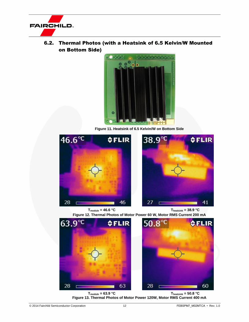
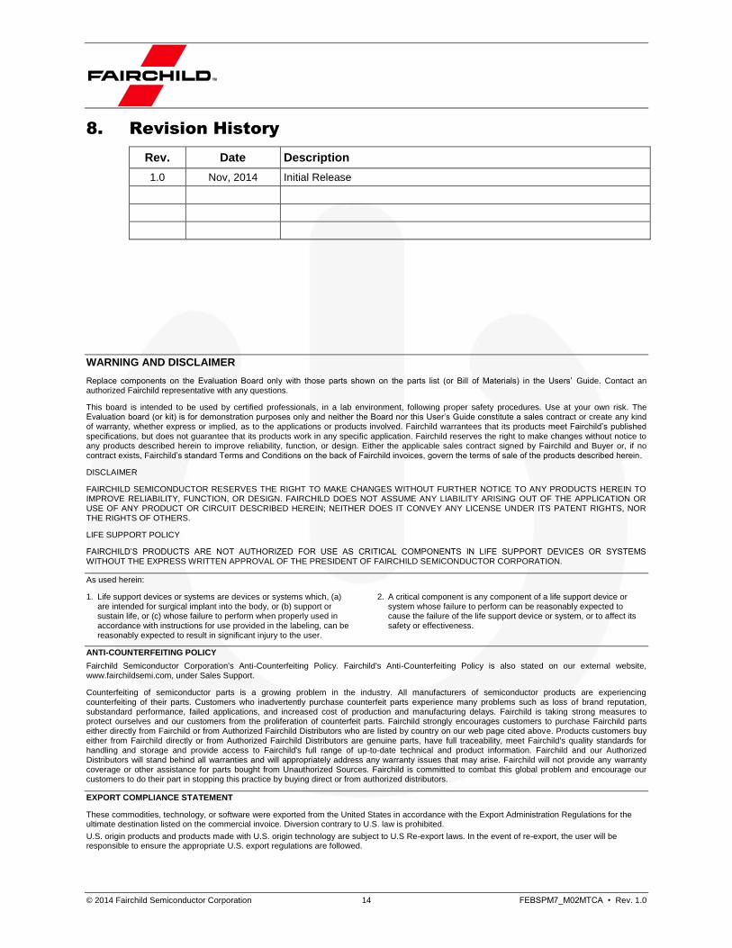
6.2. Thermal Photos (with a Heatsink of 6.5 Kelvin/W Mounted
on Bottom Side)
Figure 11. Heatsink of 6.5 Kelvin/W on Bottom Side
Tmodule = 46.6 °C Theatsink = 38.9 °C
Figure 12. Thermal Photos of Motor Power 60 W, Motor RMS Current 200 mA
Tmodule = 63.9 °C Theatsink = 50.8 °C Figure 13. Thermal Photos of Motor Power 120W, Motor RMS Current 400 mA

© 2014 Fairchild Semiconductor Corporation 13 FEBSPM7_M02MTCA • Rev. 1.0
7. Bill of Materials
Item Quantity Reference Part Manufacturer/Series
1 1 CONN1 Header_5pin_3mm_SMD_male Wurth / WR-MPC3
2 3 C1, C11, C12 10 µF / 25 V any SMD 0805
3 3 C2, C3, C10 100 nF / 50 V any SMD 0603
4 6 C4, C5, C6, C7, C8, C9 22 µF / 25 V any SMD 1206
5 1 C14 100 nF / 630 V any SMD 1812
6 10 C15, C16, C17, C18, C19, C20, C21, C26, C27, C28
330pF / 25V any SMD 0603
7 3 C22, C23, C25 1 nF / 25 V any SMD 0603
8 1 C24 3.3 nF / 25 V any SMD 0603
9 1 D1 FDLL4148 Fairchild
10 2 D2,D4 ES1J Fairchild
11 1 D3 MM3Z15VB / 200 mW Fairchild
12 1 D5 MM3Z12VC / 200 mW Fairchild
13 3 D7, D8, D9 RSFJL TAIWAN SEMICONDUCTOR
14 1 IC1 FSQ500L Fairchild
15 1 IC2 FSB70450 Fairchild
16 1 J2 Pin_Header_SMD_2x12 Wuerth / 6100xx21121
17 1 LED_15V LED_0805 any SMD LED 0805
18 1 L1 1 mH / 0.2A Wuerth / WE-PD (S)
19 1 Q1 BC847B Fairchild
20 1 R1 10 K / 0.1 W any SMD 0603
21 1 R2 1 K / 0.1 W any SMD 0603
22 1 R3 120R / 0.1 W any SMD 0603
23 1 R4 680R any SMD 0805
24 1 R5 1R / 0.1 W any SMD 0603
25 2 R6, R10 330 K / 0.25 W any SMD 1206
26 3 R7, R8, R9 15R / 0.125 W any SMD 0805
27 1 R11 5.6 K / 0.1 W any SMD 0603
28 9 R12, R13, R14, R15, R16, R17, R24, R25, R27
100R / 0.1 W any SMD 0603
29 1 R18 4.7 K / 0.1 W any SMD 0603
30 2 R19, R20 n.a. / 0.1 W any SMD 0603
31 3 R21, R22, R23 0.047R / 0.25 W any SMD 1206
32 1 R26 2.2K / 0.1 W any SMD 0603
33 1 R28 0R / 0.125 W any SMD 0805
© 2014 Fairchild Semiconductor Corporation 14 FEBSPM7_M02MTCA • Rev. 1.0
8. Revision History
Rev. Date Description
1.0 Nov, 2014 Initial Release
WARNING AND DISCLAIMER
Replace components on the Evaluation Board only with those parts shown on the parts list (or Bill of Materials) in the Users’ Guide. Contact an authorized Fairchild representative with any questions.
This board is intended to be used by certified professionals, in a lab environment, following proper safety procedures. Use at your own risk. The Evaluation board (or kit) is for demonstration purposes only and neither the Board nor this User’s Guide constitute a sales contract or create any kind of warranty, whether express or implied, as to the applications or products involved. Fairchild warrantees that its products meet Fairchild’s published specifications, but does not guarantee that its products work in any specific application. Fairchild reserves the right to make changes without notice to any products described herein to improve reliability, function, or design. Either the applicable sales contract signed by Fairchild and Buyer or, if no contract exists, Fairchild’s standard Terms and Conditions on the back of Fairchild invoices, govern the terms of sale of the products described herein.
DISCLAIMER
FAIRCHILD SEMICONDUCTOR RESERVES THE RIGHT TO MAKE CHANGES WITHOUT FURTHER NOTICE TO ANY PRODUCTS HEREIN TO IMPROVE RELIABILITY, FUNCTION, OR DESIGN. FAIRCHILD DOES NOT ASSUME ANY LIABILITY ARISING OUT OF THE APPLICATION OR USE OF ANY PRODUCT OR CIRCUIT DESCRIBED HEREIN; NEITHER DOES IT CONVEY ANY LICENSE UNDER ITS PATENT RIGHTS, NOR THE RIGHTS OF OTHERS.
LIFE SUPPORT POLICY
FAIRCHILD’S PRODUCTS ARE NOT AUTHORIZED FOR USE AS CRITICAL COMPONENTS IN LIFE SUPPORT DEVICES OR SYSTEMS WITHOUT THE EXPRESS WRITTEN APPROVAL OF THE PRESIDENT OF FAIRCHILD SEMICONDUCTOR CORPORATION.
As used herein:
1. Life support devices or systems are devices or systems which, (a) are intended for surgical implant into the body, or (b) support or sustain life, or (c) whose failure to perform when properly used in accordance with instructions for use provided in the labeling, can be reasonably expected to result in significant injury to the user.
2. A critical component is any component of a life support device or system whose failure to perform can be reasonably expected to cause the failure of the life support device or system, or to affect its safety or effectiveness.
ANTI-COUNTERFEITING POLICY
Fairchild Semiconductor Corporation's Anti-Counterfeiting Policy. Fairchild's Anti-Counterfeiting Policy is also stated on our external website, www.fairchildsemi.com, under Sales Support.
Counterfeiting of semiconductor parts is a growing problem in the industry. All manufacturers of semiconductor products are experiencing counterfeiting of their parts. Customers who inadvertently purchase counterfeit parts experience many problems such as loss of brand reputation, substandard performance, failed applications, and increased cost of production and manufacturing delays. Fairchild is taking strong measures to protect ourselves and our customers from the proliferation of counterfeit parts. Fairchild strongly encourages customers to purchase Fairchild parts either directly from Fairchild or from Authorized Fairchild Distributors who are listed by country on our web page cited above. Products customers buy either from Fairchild directly or from Authorized Fairchild Distributors are genuine parts, have full traceability, meet Fairchild's quality standards for handling and storage and provide access to Fairchild's full range of up-to-date technical and product information. Fairchild and our Authorized Distributors will stand behind all warranties and will appropriately address any warranty issues that may arise. Fairchild will not provide any warranty coverage or other assistance for parts bought from Unauthorized Sources. Fairchild is committed to combat this global problem and encourage our customers to do their part in stopping this practice by buying direct or from authorized distributors.
EXPORT COMPLIANCE STATEMENT
These commodities, technology, or software were exported from the United States in accordance with the Export Administration Regulations for the ultimate destination listed on the commercial invoice. Diversion contrary to U.S. law is prohibited.
U.S. origin products and products made with U.S. origin technology are subject to U.S Re-export laws. In the event of re-export, the user will be responsible to ensure the appropriate U.S. export regulations are followed.
www.onsemi.com1
ON Semiconductor and are trademarks of Semiconductor Components Industries, LLC dba ON Semiconductor or its subsidiaries in the United States and/or other countries.ON Semiconductor owns the rights to a number of patents, trademarks, copyrights, trade secrets, and other intellectual property. A listing of ON Semiconductor’s product/patentcoverage may be accessed at www.onsemi.com/site/pdf/Patent−Marking.pdf. ON Semiconductor reserves the right to make changes without further notice to any products herein.ON Semiconductor makes no warranty, representation or guarantee regarding the suitability of its products for any particular purpose, nor does ON Semiconductor assume any liabilityarising out of the application or use of any product or circuit, and specifically disclaims any and all liability, including without limitation special, consequential or incidental damages.Buyer is responsible for its products and applications using ON Semiconductor products, including compliance with all laws, regulations and safety requirements or standards,regardless of any support or applications information provided by ON Semiconductor. “Typical” parameters which may be provided in ON Semiconductor data sheets and/orspecifications can and do vary in different applications and actual performance may vary over time. All operating parameters, including “Typicals” must be validated for each customerapplication by customer’s technical experts. ON Semiconductor does not convey any license under its patent rights nor the rights of others. ON Semiconductor products are notdesigned, intended, or authorized for use as a critical component in life support systems or any FDA Class 3 medical devices or medical devices with a same or similar classificationin a foreign jurisdiction or any devices intended for implantation in the human body. Should Buyer purchase or use ON Semiconductor products for any such unintended or unauthorizedapplication, Buyer shall indemnify and hold ON Semiconductor and its officers, employees, subsidiaries, affiliates, and distributors harmless against all claims, costs, damages, andexpenses, and reasonable attorney fees arising out of, directly or indirectly, any claim of personal injury or death associated with such unintended or unauthorized use, even if suchclaim alleges that ON Semiconductor was negligent regarding the design or manufacture of the part. ON Semiconductor is an Equal Opportunity/Affirmative Action Employer. Thisliterature is subject to all applicable copyright laws and is not for resale in any manner.
PUBLICATION ORDERING INFORMATIONN. American Technical Support: 800−282−9855 Toll FreeUSA/Canada
Europe, Middle East and Africa Technical Support:Phone: 421 33 790 2910
Japan Customer Focus CenterPhone: 81−3−5817−1050
www.onsemi.com
LITERATURE FULFILLMENT:Literature Distribution Center for ON Semiconductor19521 E. 32nd Pkwy, Aurora, Colorado 80011 USAPhone: 303−675−2175 or 800−344−3860 Toll Free USA/CanadaFax: 303−675−2176 or 800−344−3867 Toll Free USA/CanadaEmail: [email protected]
ON Semiconductor Website: www.onsemi.com
Order Literature: http://www.onsemi.com/orderlit
For additional information, please contact your localSales Representative
© Semiconductor Components Industries, LLC