internship report metuge final copy
TRANSCRIPT
UNIVERSITY OF YAOUNDE I
NATIONAL ADVANCED SCHOOL OF
ENGINEERING
DEPARTEMENT OF INDUSTRIAL AND
MECHANICAL ENGINEERING
FOSTER WHEELER FRANCE
92, QUAI DE ERCY 75597 PARIS CEDEX 12
FRANCE
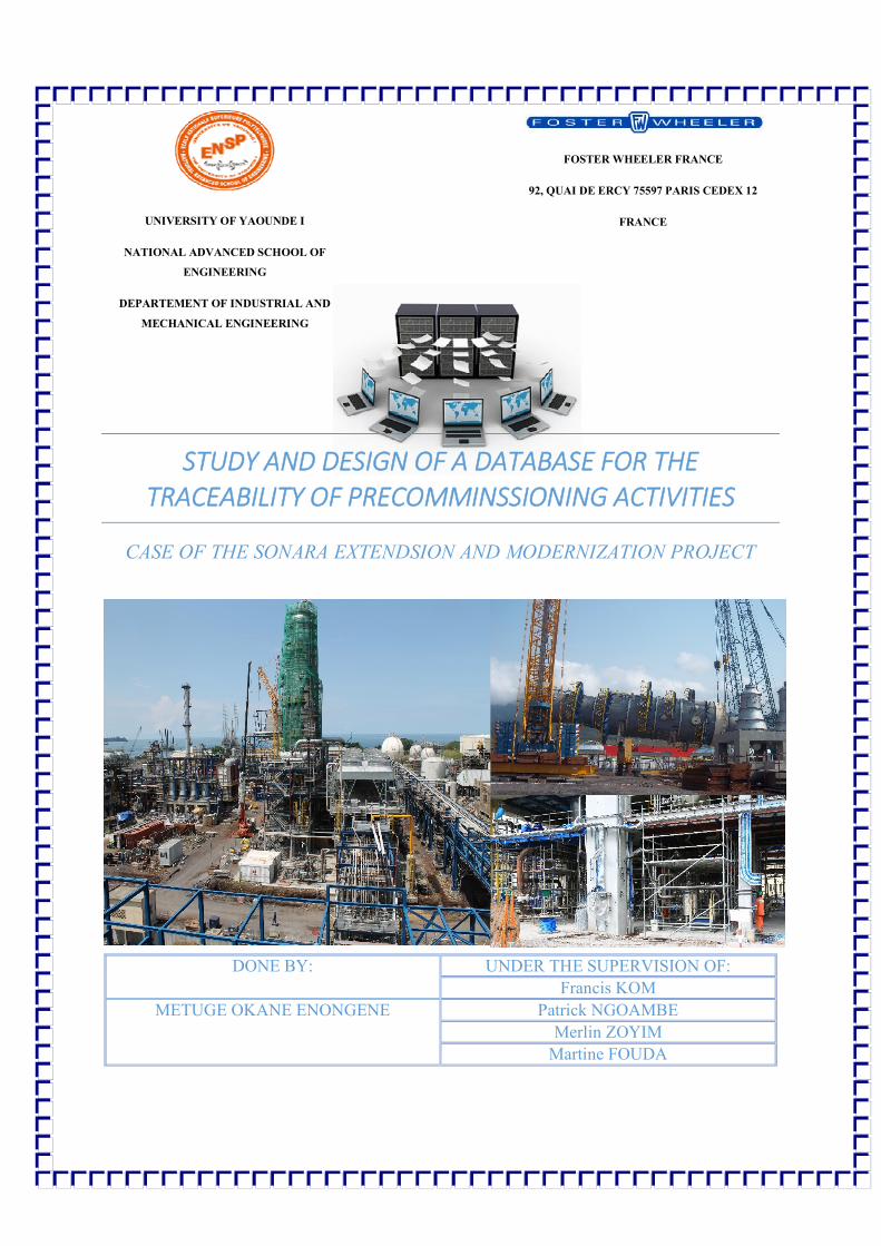
STUDY AND DESIGN OF A DATABASE FOR THE TRACEABILITY OF PRECOMMINSSIONING ACTIVITIES
CASE OF THE SONARA EXTENDSION AND MODERNIZATION PROJECT
DONE BY: UNDER THE SUPERVISION OF:
Francis KOM
METUGE OKANE ENONGENE Patrick NGOAMBE
Merlin ZOYIM
Martine FOUDA
METUGE OKANE ENONGENE 1
STUDY AND DESIGN OF A DATABASE FOR THE TRACEABILITY OF PRECOMMINSSIONING ACTIVITIES
DEDICATION
To my family and the staff members of QAQC at Foster Wheeler
METUGE OKANE ENONGENE 2
STUDY AND DESIGN OF A DATABASE FOR THE TRACEABILITY OF PRECOMMINSSIONING ACTIVITIES
ACKNOWLEGEMENTS
This report is based on my internship at Foster Wheeler, and I wish to extend my gratitude to the
Foster Wheeler staff for their friendly attitude towards me and to appreciate the family spirit that
reigns among the staff members.
Special thanks to:
Mr. DAOUDA Diop (The Resident Chief Project manager) and Mr. Fabrice MELOMBI
(the office manager) for receiving me at the company, which permitted me to do my
internship.
The Staff of QAQC ( Mr. Francis KOM, Mr. Patrick NGOAMBE, Mr. Merlin TIOGUIM
and Miss Martine FOUDA) for receiving me in their department, supervising my work as
well as guiding and teaching me a lot about quality
Mr. Sylvain BESSALA for his help and invaluable advice
Armel TSOGO for his help.
METUGE OKANE ENONGENE 3
STUDY AND DESIGN OF A DATABASE FOR THE TRACEABILITY OF PRECOMMINSSIONING ACTIVITIES
LIST OF FIGURES
Figure 1 The Global E&C organizational flowchart (2) ............................................................... 15
Figure 2 Map showing the world distribution of Foster Wheeler branches (2) ............................ 16
Figure 3 The organizational chart for FWCam (2) ....................................................................... 18
Figure 4 Organizational chart of the QAQC department .............................................................. 20
Figure 5 Pre-commissioning Activities Chart (3) ......................................................................... 22
Figure 6 Entity designer class diagram......................................................................................... 32
Figure 7. Pre-commissioning progress flow ................................................................................. 33
Figure 8 Application use Case Diagram ....................................................................................... 35
Figure 9 Login activity diagram ................................................................................................... 40
Figure 10 Administrator functioning flow chart ........................................................................... 41
Figure 11 Create user activity Diagram ........................................................................................ 42
Figure 12 Modify user activity diagram ....................................................................................... 43
Figure 13 Delete user activity diagram ......................................................................................... 44
Figure 14 Create Group activity diagram ..................................................................................... 44
Figure 15 Modify Group activity Diagram ................................................................................... 45
Figure 16 Delete Group activity diagram ..................................................................................... 46
Figure 17 Chart depicting presentation of the database for all the users ...................................... 47
METUGE OKANE ENONGENE 4
STUDY AND DESIGN OF A DATABASE FOR THE TRACEABILITY OF PRECOMMINSSIONING ACTIVITIES
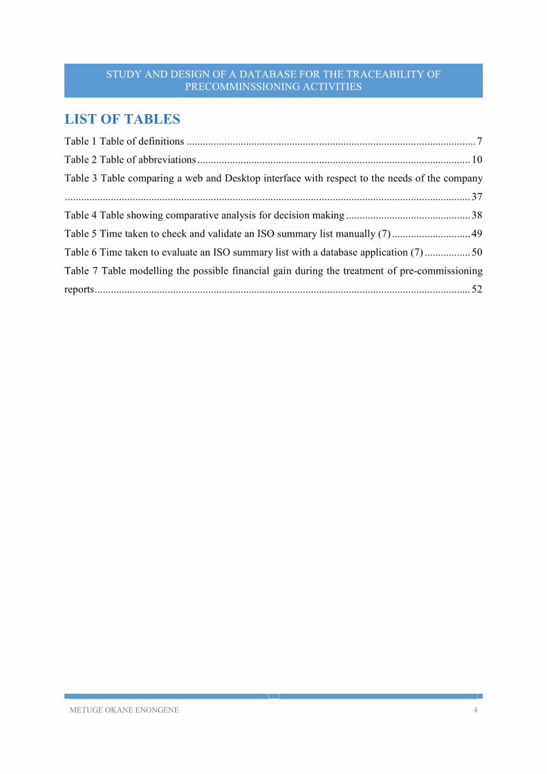
LIST OF TABLES
Table 1 Table of definitions ........................................................................................................... 7
Table 2 Table of abbreviations ..................................................................................................... 10
Table 3 Table comparing a web and Desktop interface with respect to the needs of the company
...................................................................................................................................................... 37
Table 4 Table showing comparative analysis for decision making .............................................. 38
Table 5 Time taken to check and validate an ISO summary list manually (7) ............................. 49
Table 6 Time taken to evaluate an ISO summary list with a database application (7) ................. 50
Table 7 Table modelling the possible financial gain during the treatment of pre-commissioning
reports ........................................................................................................................................... 52
METUGE OKANE ENONGENE 5
STUDY AND DESIGN OF A DATABASE FOR THE TRACEABILITY OF PRECOMMINSSIONING ACTIVITIES
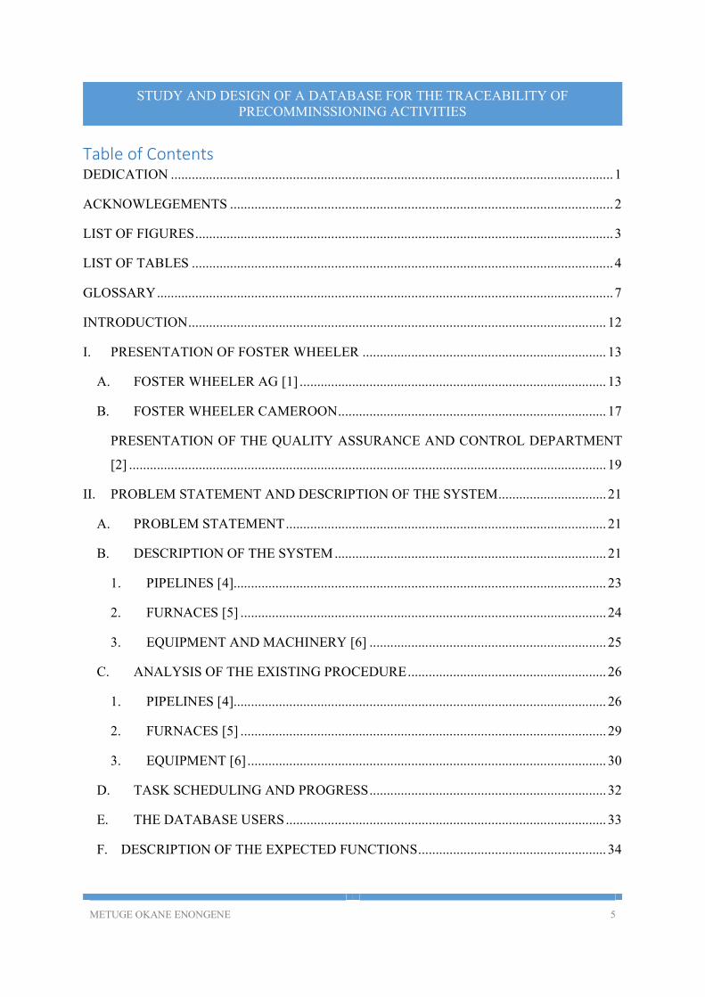
Table of Contents DEDICATION ............................................................................................................................... 1
ACKNOWLEGEMENTS .............................................................................................................. 2
LIST OF FIGURES ........................................................................................................................ 3
LIST OF TABLES ......................................................................................................................... 4
GLOSSARY ................................................................................................................................... 7
INTRODUCTION ........................................................................................................................ 12
I. PRESENTATION OF FOSTER WHEELER ...................................................................... 13
A. FOSTER WHEELER AG [1] ........................................................................................ 13
B. FOSTER WHEELER CAMEROON ............................................................................. 17
PRESENTATION OF THE QUALITY ASSURANCE AND CONTROL DEPARTMENT
[2] ......................................................................................................................................... 19
II. PROBLEM STATEMENT AND DESCRIPTION OF THE SYSTEM ............................... 21
A. PROBLEM STATEMENT ............................................................................................ 21
B. DESCRIPTION OF THE SYSTEM .............................................................................. 21
1. PIPELINES [4]........................................................................................................... 23
2. FURNACES [5] ......................................................................................................... 24
3. EQUIPMENT AND MACHINERY [6] .................................................................... 25
C. ANALYSIS OF THE EXISTING PROCEDURE ......................................................... 26
1. PIPELINES [4]........................................................................................................... 26
2. FURNACES [5] ......................................................................................................... 29
3. EQUIPMENT [6] ....................................................................................................... 30
D. TASK SCHEDULING AND PROGRESS .................................................................... 32
E. THE DATABASE USERS ............................................................................................ 33
F. DESCRIPTION OF THE EXPECTED FUNCTIONS ...................................................... 34
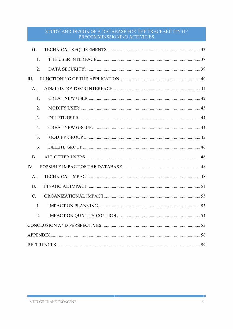
METUGE OKANE ENONGENE 6
STUDY AND DESIGN OF A DATABASE FOR THE TRACEABILITY OF PRECOMMINSSIONING ACTIVITIES
G. TECHNICAL REQUIREMENTS ................................................................................. 37
1. THE USER INTERFACE .......................................................................................... 37
2. DATA SECURITY .................................................................................................... 39
III. FUNCTIONING OF THE APPLICATION ...................................................................... 40
A. ADMINISTRATOR’S INTERFACE ............................................................................ 41
1. CREAT NEW USER ................................................................................................. 42
2. MODIFY USER ......................................................................................................... 43
3. DELETE USER ......................................................................................................... 44
4. CREAT NEW GROUP .............................................................................................. 44
5. MODIFY GROUP ..................................................................................................... 45
6. DELETE GROUP ...................................................................................................... 46
B. ALL OTHER USERS .................................................................................................... 46
IV. POSSIBLE IMPACT OF THE DATABASE .................................................................... 48
A. TECHNICAL IMPACT ................................................................................................. 48
B. FINANCIAL IMPACT .................................................................................................. 51
C. ORGANIZATIONAL IMPACT .................................................................................... 53
1. IMPACT ON PLANNING......................................................................................... 53
2. IMPACT ON QUALITY CONTROL ....................................................................... 54
CONCLUSION AND PERSPECTIVES...................................................................................... 55
APPENDIX .................................................................................................................................. 56
REFERENCES ............................................................................................................................. 59
METUGE OKANE ENONGENE 7
STUDY AND DESIGN OF A DATABASE FOR THE TRACEABILITY OF PRECOMMINSSIONING ACTIVITIES
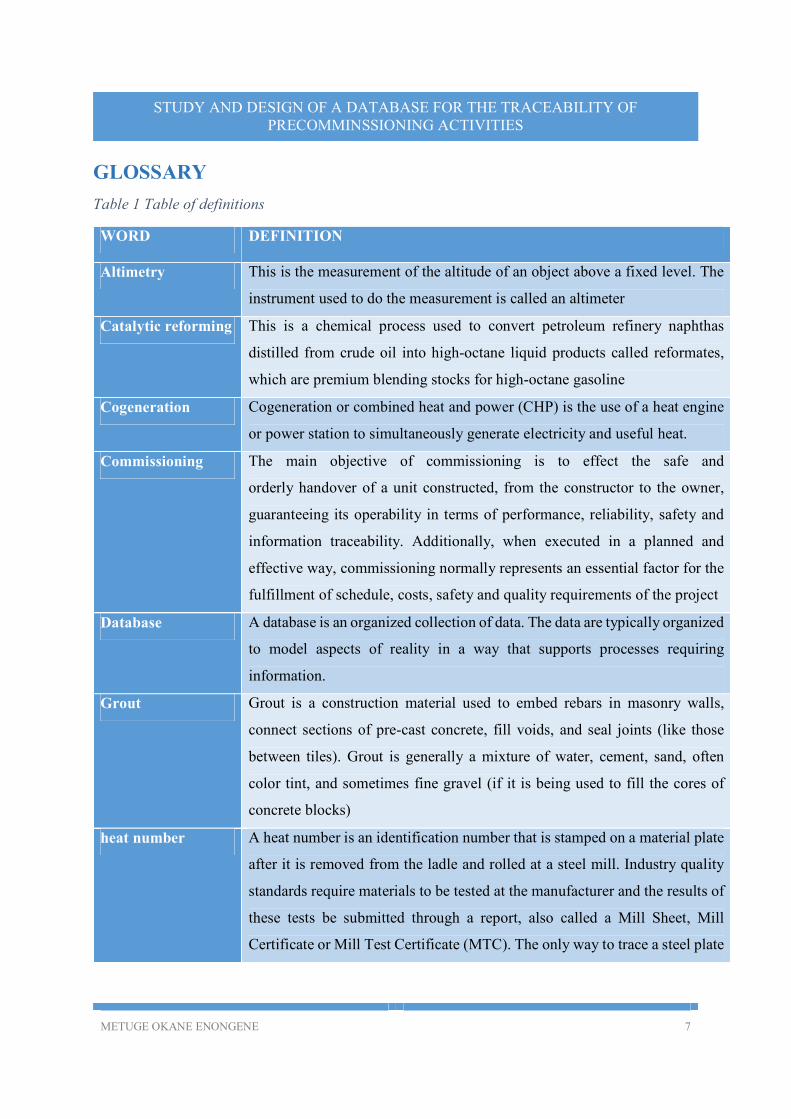
GLOSSARY
Table 1 Table of definitions
WORD DEFINITION
Altimetry This is the measurement of the altitude of an object above a fixed level. The
instrument used to do the measurement is called an altimeter
Catalytic reforming This is a chemical process used to convert petroleum refinery naphthas
distilled from crude oil into high-octane liquid products called reformates,
which are premium blending stocks for high-octane gasoline
Cogeneration Cogeneration or combined heat and power (CHP) is the use of a heat engine
or power station to simultaneously generate electricity and useful heat.
Commissioning The main objective of commissioning is to effect the safe and
orderly handover of a unit constructed, from the constructor to the owner,
guaranteeing its operability in terms of performance, reliability, safety and
information traceability. Additionally, when executed in a planned and
effective way, commissioning normally represents an essential factor for the
fulfillment of schedule, costs, safety and quality requirements of the project
Database A database is an organized collection of data. The data are typically organized
to model aspects of reality in a way that supports processes requiring
information.
Grout Grout is a construction material used to embed rebars in masonry walls,
connect sections of pre-cast concrete, fill voids, and seal joints (like those
between tiles). Grout is generally a mixture of water, cement, sand, often
color tint, and sometimes fine gravel (if it is being used to fill the cores of
concrete blocks)
heat number A heat number is an identification number that is stamped on a material plate
after it is removed from the ladle and rolled at a steel mill. Industry quality
standards require materials to be tested at the manufacturer and the results of
these tests be submitted through a report, also called a Mill Sheet, Mill
Certificate or Mill Test Certificate (MTC). The only way to trace a steel plate
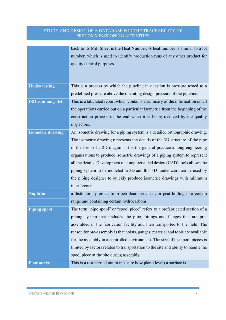
METUGE OKANE ENONGENE 8
STUDY AND DESIGN OF A DATABASE FOR THE TRACEABILITY OF PRECOMMINSSIONING ACTIVITIES
back to its Mill Sheet is the Heat Number. A heat number is similar to a lot
number, which is used to identify production runs of any other product for
quality control purposes.
Hydro testing This is a process by which the pipeline in question is pressure tested to a
predefined pressure above the operating design pressure of the pipeline.
ISO summary list This is a tabulated report which contains a summary of the information on all
the operations carried out on a particular isometric from the beginning of the
construction process to the end when it is being received by the quality
inspectors.
Isometric drawing An isometric drawing for a piping system is a detailed orthographic drawing.
The isometric drawing represents the details of the 3D structure of the pipe
in the form of a 2D diagram. It is the general practice among engineering
organizations to produce isometric drawings of a piping system to represent
all the details. Development of computer aided design (CAD) tools allows the
piping system to be modeled in 3D and this 3D model can then be used by
the piping designer to quickly produce isometric drawings with minimum
interference.
Naphtha a distillation product from petroleum, coal tar, or peat boiling in a certain
range and containing certain hydrocarbons
Piping spool The term “pipe spool” or “spool piece” refers to a prefabricated section of a
piping system that includes the pipe, fittings and flanges that are pre-
assembled in the fabrication facility and then transported to the field. The
reason for pre-assembly is that hoists, gauges, material and tools are available
for the assembly in a controlled environment. The size of the spool pieces is
limited by factors related to transportation to the site and ability to handle the
spool piece at the site during assembly.
Planimetry This is a test carried out to measure how plane(level) a surface is
METUGE OKANE ENONGENE 9
STUDY AND DESIGN OF A DATABASE FOR THE TRACEABILITY OF PRECOMMINSSIONING ACTIVITIES
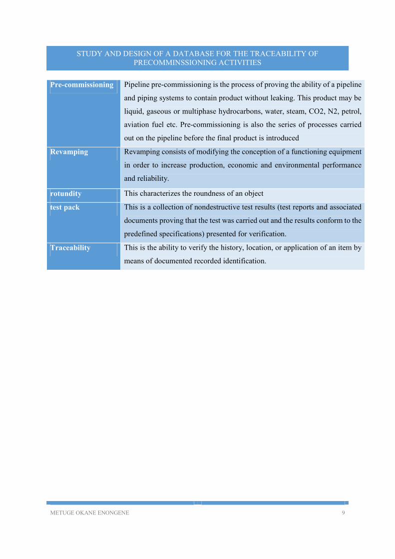
Pre-commissioning Pipeline pre-commissioning is the process of proving the ability of a pipeline
and piping systems to contain product without leaking. This product may be
liquid, gaseous or multiphase hydrocarbons, water, steam, CO2, N2, petrol,
aviation fuel etc. Pre-commissioning is also the series of processes carried
out on the pipeline before the final product is introduced
Revamping Revamping consists of modifying the conception of a functioning equipment
in order to increase production, economic and environmental performance
and reliability.
rotundity This characterizes the roundness of an object
test pack This is a collection of nondestructive test results (test reports and associated
documents proving that the test was carried out and the results conform to the
predefined specifications) presented for verification.
Traceability This is the ability to verify the history, location, or application of an item by
means of documented recorded identification.
METUGE OKANE ENONGENE 10
STUDY AND DESIGN OF A DATABASE FOR THE TRACEABILITY OF PRECOMMINSSIONING ACTIVITIES
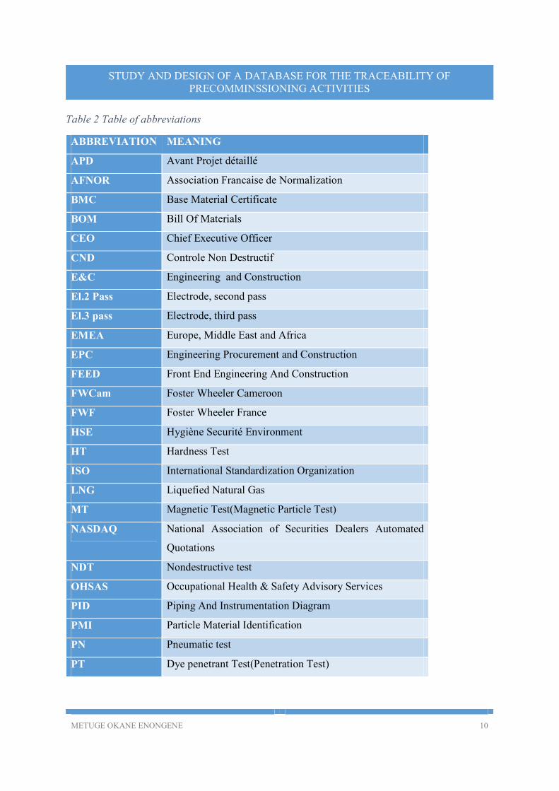
Table 2 Table of abbreviations
ABBREVIATION MEANING
APD Avant Projet détaillé
AFNOR Association Francaise de Normalization
BMC Base Material Certificate
BOM Bill Of Materials
CEO Chief Executive Officer
CND Controle Non Destructif
E&C Engineering and Construction
El.2 Pass Electrode, second pass
El.3 pass Electrode, third pass
EMEA Europe, Middle East and Africa
EPC Engineering Procurement and Construction
FEED Front End Engineering And Construction
FWCam Foster Wheeler Cameroon
FWF Foster Wheeler France
HSE Hygiène Securité Environment
HT Hardness Test
ISO International Standardization Organization
LNG Liquefied Natural Gas
MT Magnetic Test(Magnetic Particle Test)
NASDAQ National Association of Securities Dealers Automated
Quotations
NDT Nondestructive test
OHSAS Occupational Health & Safety Advisory Services
PID Piping And Instrumentation Diagram
PMI Particle Material Identification
PN Pneumatic test
PT Dye penetrant Test(Penetration Test)
METUGE OKANE ENONGENE 11
STUDY AND DESIGN OF A DATABASE FOR THE TRACEABILITY OF PRECOMMINSSIONING ACTIVITIES
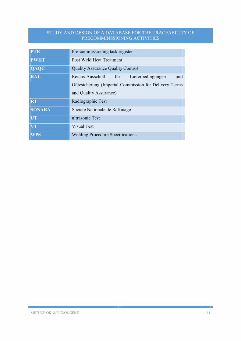
PTR Pre-commissioning task register
PWHT Post Weld Heat Treatment
QAQC Quality Assurance Quality Control
RAL Reichs-Ausschuß für Lieferbedingungen und
Gütesicherung (Imperial Commission for Delivery Terms
and Quality Assurance)
RT Radiographic Test
SONARA Societé Nationale de Raffinage
UT ultrasonic Test
VT Visual Test
WPS Welding Procedure Specifications
METUGE OKANE ENONGENE 12
STUDY AND DESIGN OF A DATABASE FOR THE TRACEABILITY OF PRECOMMINSSIONING ACTIVITIES
INTRODUCTION
The National Refining Company, popularly known as SONARA, in order to increase its
production capacity from 2.1 million tons per year to 3.5 million tons launched in 2010, the first
phase of it’s extension and modernization project of contract type EPC.
The first phase of the said project, has as project management body Foster Wheeler France and
involves the revamping of previously constructed units, the construction of new units for vacuum
distillation, catalytic reforming, cogeneration of electricity, vapor production and the building of
new storage tanks.
At a certain level during the evolution of the project, pre-commissioning activities are launched,
and at the end of the project commissioning activities are then launched to hand over the finished
product that emanated from the project. The main problems that are encountered during pre-
commissioning are amongst other, the management of pre-commissioning activities and the
traceability of pre-commissioning information. In the case of the construction activities being
carried out at the SONARA site for example, this information is very important because if the
product from the project has a problem before, during or after commissioning, it is the pre-
commissioning information that can prove that the product met the specifications of the client and
followed the norms that are applicable to each of the activities that are involved in the construction
process.
For efficient management of the traceability of this information thus it is important that the
information be managed numerically, using a robust database application.
This work is therefore aimed at studying the system being used actually, the proposal of a model
for the database to be implemented and the study of the impact of the database on pre-
commissioning activities.
METUGE OKANE ENONGENE 13
STUDY AND DESIGN OF A DATABASE FOR THE TRACEABILITY OF PRECOMMINSSIONING ACTIVITIES
I. PRESENTATION OF FOSTER WHEELER
A. FOSTER WHEELER AG [1]
Foster Wheeler AG is a global engineering, construction and project management firm that was
formed in 1927 from a merger of two companies based in the United States: the Power Specialty
Company (which replaced Water Works Supply Company, created by the Foster family in 1884)
and the Wheeler Condenser & Engineering Company, whose roots go back to 1891.
In its early years, the company’s main business was the design and manufacture of boilers and
related equipment. Over the years, the company grew internationally through acquisitions, and it
entered the engineering and construction business in the 1920s. Foster Wheeler was listed on the
New York Stock Exchange in 1929 and was listed on the Nasdaq Stock Exchange in 2005.
The corporate headquarters were originally in New York City but later moved to New Jersey.
Today, the company’s executive office is located in the United Kingdom.
a) Identification, Locations
Foster Wheeler AG was created in 1927
Corporate headquarters found in New Jersey(USA)
Executive headquarters found in the United Kingdom
It has a capital of $4 billion
Private firm with more than 15000 shareholders
Listed on the New York Stock Exchange in 1929
Lister on the NASDAQ Stock Exchange in 2005
It is one of the leading global companies in Engineering, Procurement and construction
Management of projects.
It has permanent braches in 25 countries
It’s main activities are divided into two groups:
o Global Engineering and Construction(E &C) Group
o Global Power Group
METUGE OKANE ENONGENE 14
STUDY AND DESIGN OF A DATABASE FOR THE TRACEABILITY OF PRECOMMINSSIONING ACTIVITIES
b) Activities
(1) The Global Power Group
The Global Power Group is renowned in the following fields:
Furnaces and steam boilers
Auxiliary equipment
Maintenance and other Engineering services
Design of engineering structures and equipment
Fabrication
Assembly of engineering structures.
(2) The Global Engineering and Construction Group (E&C)
Their expertise lies in the fields of:
Upstream oil and gas
Midstream, including liquefaction of LNG, gas to liquids, coal to liquids, gasification,
capture and storage of carbon.
Refining, including delayed cooking
Petrochemical units
Chemical units, including coal to chemicals
Pharmacy and biotechnology
Metals and mines
Energetic and power stations (thermal, wind, etc.)
Environmental Engineering
Engineering and project studies
o FEED(APD)
o Project management
o Engineering
o Purchase
o Construction
And the global engineering and construction group constituted 61% of the company’s capital in
2011, with untaxed profits valued at 53%. It employed approximately 9000 workers.
METUGE OKANE ENONGENE 15
STUDY AND DESIGN OF A DATABASE FOR THE TRACEABILITY OF PRECOMMINSSIONING ACTIVITIES
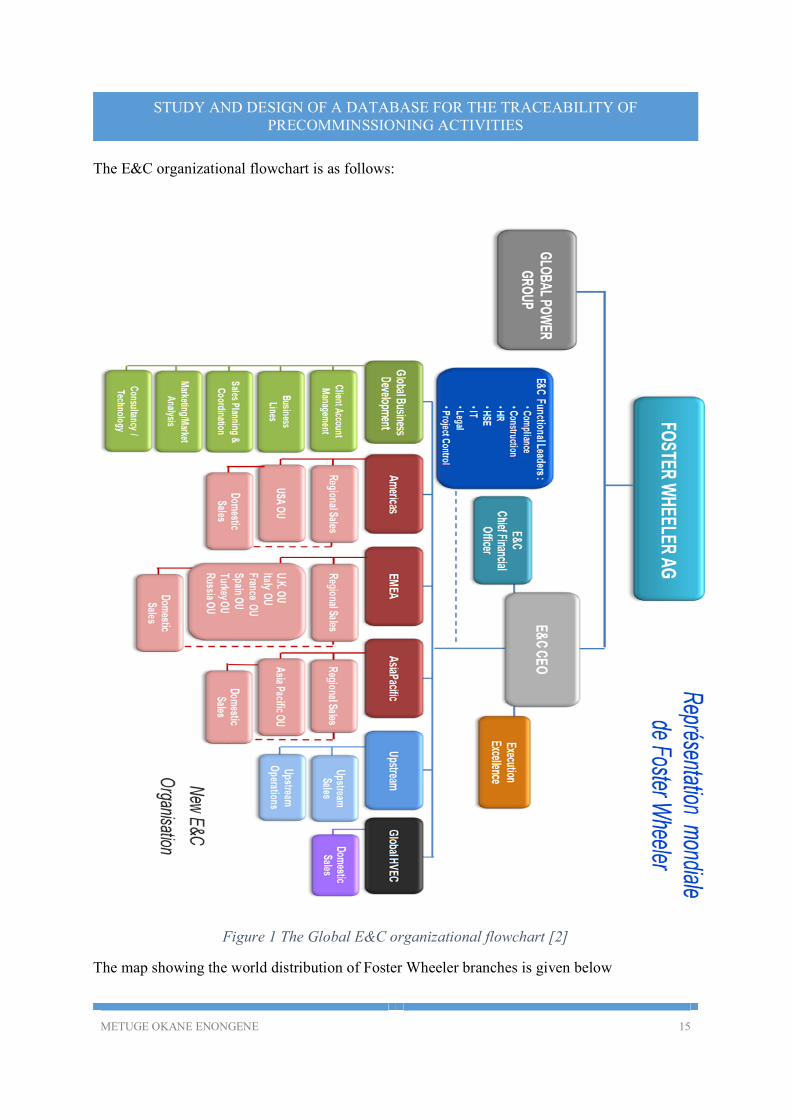
The E&C organizational flowchart is as follows:
Figure 1 The Global E&C organizational flowchart [2]
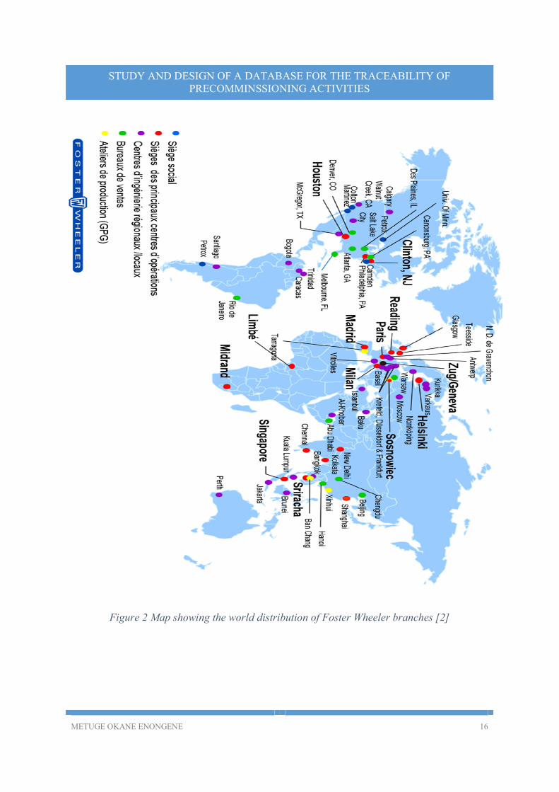
The map showing the world distribution of Foster Wheeler branches is given below
METUGE OKANE ENONGENE 16
STUDY AND DESIGN OF A DATABASE FOR THE TRACEABILITY OF PRECOMMINSSIONING ACTIVITIES
Figure 2 Map showing the world distribution of Foster Wheeler branches [2]
METUGE OKANE ENONGENE 17
STUDY AND DESIGN OF A DATABASE FOR THE TRACEABILITY OF PRECOMMINSSIONING ACTIVITIES
B. FOSTER WHEELER CAMEROON
Under the supervision of Foster Wheeler France, Foster wheeler Cameroon was created as a branch
of Foster Wheeler France in 2010 to manage the SONARA extension project, this followed by the
creation of Foster Wheeler Cameroon in 2013.
Foster Wheeler Cameroon (FWCam) has an operating capital of 1 billion FCFA (statistic
from 2012).
The number of employees in September 2014 was evaluated at 57 with the following
distribution:
o Piping 5
o Civil Engineering 6
o “ Marches de travauxs” 4
o Electricity 3
o Field Engineering and BE 12
o Doc control 2
o Planning 2
o Steel frameworks 4
o Commercial 1
o Administrative management 2
o Offsite 1
o Instrumentation 3
o HSE 6
o Administration 7
o QA-QC 4
Some employees have more than one function.
METUGE OKANE ENONGENE 18
STUDY AND DESIGN OF A DATABASE FOR THE TRACEABILITY OF PRECOMMINSSIONING ACTIVITIES
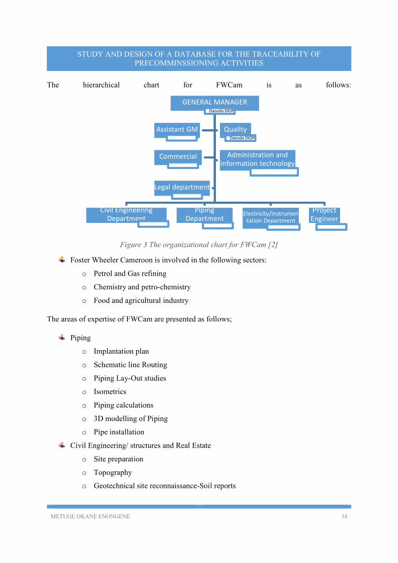
The hierarchical chart for FWCam is as follows:
Figure 3 The organizational chart for FWCam [2]
Foster Wheeler Cameroon is involved in the following sectors:
o Petrol and Gas refining
o Chemistry and petro-chemistry
o Food and agricultural industry
The areas of expertise of FWCam are presented as follows;
Piping
o Implantation plan
o Schematic line Routing
o Piping Lay-Out studies
o Isometrics
o Piping calculations
o 3D modelling of Piping
o Pipe installation
Civil Engineering/ structures and Real Estate
o Site preparation
o Topography
o Geotechnical site reconnaissance-Soil reports
GENERAL MANAGERDaouda DIOP
Civil Engineering Department
Piping Department
Electricity/Instrumentation Department
Project Engineer
Assistant GM QualityDaouda DIOP
Commercial Administration and information technology
Legal department
METUGE OKANE ENONGENE 19
STUDY AND DESIGN OF A DATABASE FOR THE TRACEABILITY OF PRECOMMINSSIONING ACTIVITIES
o Earthworks engineering and site excavation
o Etc.
Electrical engineering and instrumentation
o Conception of electrical networks
o Lighting
o Earthing
o Cathodic protection
o Etc.
Thermal Transfer
o Thermal system design
o Mechanical system design
o Etc.
Process engineering
Construction
Project planning
Quality control and assurance
HSE
PRESENTATION OF THE QUALITY ASSURANCE AND CONTROL
DEPARTMENT [2]
With respect to quality assurance and control, Foster wheeler is certified ISO 9001:2008-Quality
management system [Appendix 1], ISO 14001:2004-Environmental management system
[Appendix 2] and OHSAS 18001:2007-Occupational health and safety [Appendix 3] by the French
organization AFNOR for the following activities:
Project management
Design
Engineering
Equipment management and supervision of construction
Pre-commissioning
Commissioning
METUGE OKANE ENONGENE 20
STUDY AND DESIGN OF A DATABASE FOR THE TRACEABILITY OF PRECOMMINSSIONING ACTIVITIES
Operation and/or maintenance of industrial infrastructure and plants relating to power
generation
Upstream oil and gas
Oil refining
Petrochemicals
Chemicals
Pharmaceuticals
Waste to energy recovery
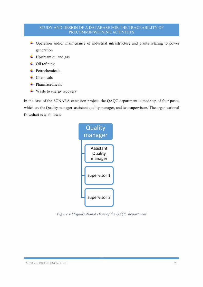
In the case of the SONARA extension project, the QAQC department is made up of four posts,
which are the Quality manager, assistant quality manager, and two supervisors. The organizational
flowchart is as follows:
Figure 4 Organizational chart of the QAQC department
Quality manager
Assistant Quality
manager
supervisor 1
supervisor 2
METUGE OKANE ENONGENE 21
STUDY AND DESIGN OF A DATABASE FOR THE TRACEABILITY OF PRECOMMINSSIONING ACTIVITIES
II. PROBLEM STATEMENT AND DESCRIPTION OF THE
SYSTEM
A. PROBLEM STATEMENT
During pre-commissioning, the pipes, furnaces, equipment and machinery installed at the sonara
refinery during the first phase of the SONARA EXTENSION PROJECT which has as
Engineering, Procurement and Construction project manager, the international company FOSTER
WHEELER, it is important to ensure that all the pre-commissioned information is traceable, thus
the topic STUDY AND DESIGN OF A DATABASE FOR THE TRACEABILITY OF
PRECOMMINSSIONING ACTIVITIES; CASE OF THE SONARA REFINERY
MODERNISATION AND EXTENSION.
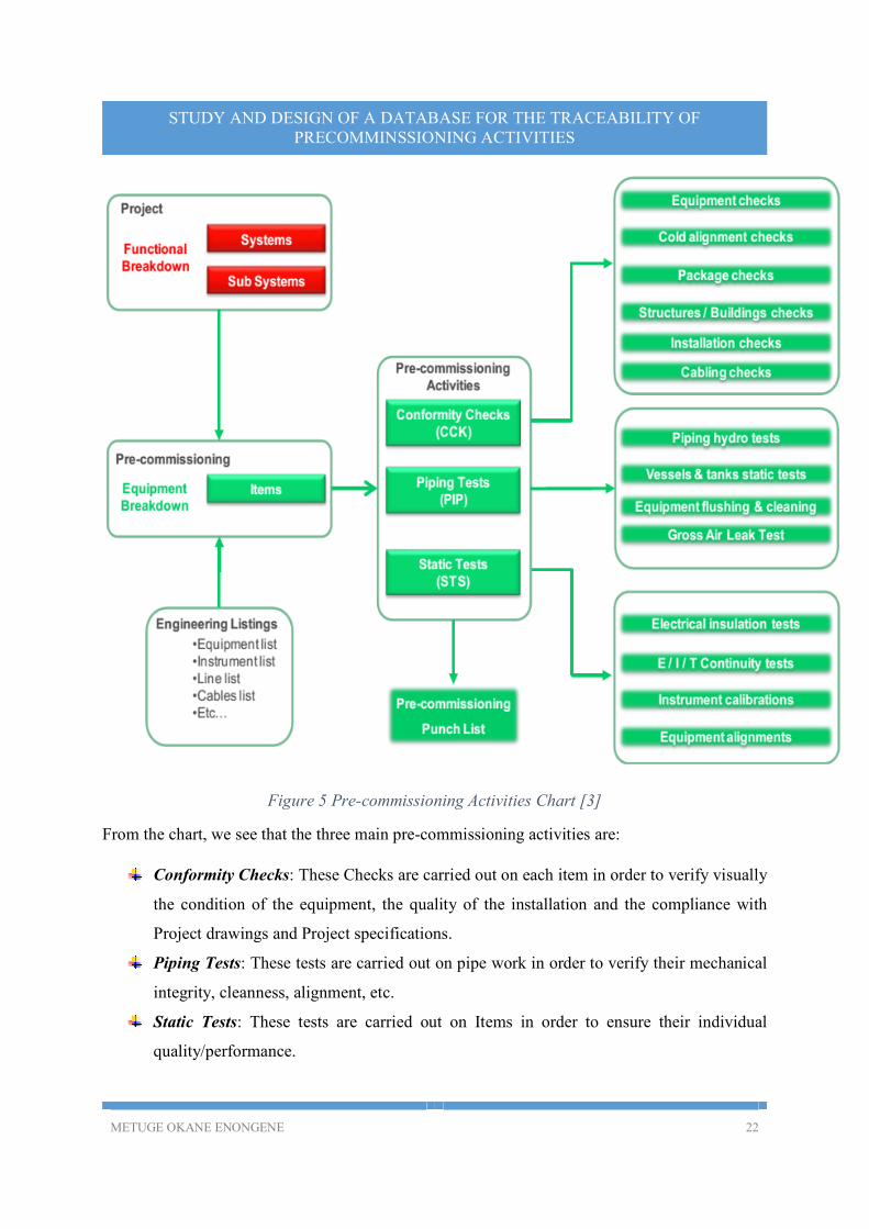
B. DESCRIPTION OF THE SYSTEM
Before pre-commissioning, the system which is the project as a whole is divided into subsystems,
and pre-commissioning is done following these subsystems. A functional decomposition of the
entire system is thus done and the smallest commissionable part of the system is called an item.
These items are the components that are subject to pre-commissioning. From the pre-
commissioning engineering point of view,
A System is a major subdivision of a plant, being either process or utility, which performs
a major operational function of the plant.
A Subsystem is a further subdivision of a System, which performs a partial operational
function of the System, with little or no interference from the other Sub-systems. The
Sub-system is the basic unit for Commissioning.
An item is the smallest component of a subsystem identified by a tag, and subject to one
or several Pre-commissioning tasks: Checks and /or Tests.
After pre-commissioning is successfully carried out on a system, a certificate called the Ready for
commissioning (RFC) certificate is issued, this permits the project to proceed to the
commissioning phase.
The chart that follows gives a general idea of the activities involved during the pre-commissioning
of a system.
METUGE OKANE ENONGENE 22
STUDY AND DESIGN OF A DATABASE FOR THE TRACEABILITY OF PRECOMMINSSIONING ACTIVITIES
Figure 5 Pre-commissioning Activities Chart [3]
From the chart, we see that the three main pre-commissioning activities are:
Conformity Checks: These Checks are carried out on each item in order to verify visually
the condition of the equipment, the quality of the installation and the compliance with
Project drawings and Project specifications.
Piping Tests: These tests are carried out on pipe work in order to verify their mechanical
integrity, cleanness, alignment, etc.
Static Tests: These tests are carried out on Items in order to ensure their individual
quality/performance.
METUGE OKANE ENONGENE 23
STUDY AND DESIGN OF A DATABASE FOR THE TRACEABILITY OF PRECOMMINSSIONING ACTIVITIES
In the case where there is a problem during pre-commissioning, a punch list (a list of punch items)
is opened. A Punch Item is an uncompleted, unsatisfactory or missing work, identified as being
part of a scope of work, which shall be cleared during the course of the project at a specific
contractual milestone. The RFC certificate is only issued after the closure of the punch list relating
to the system being pre-commissioned.
In our case, the system will be managed in terms of piping, furnaces and Equipment and
machinery. The following is how the system is subdivided as well as the properties of each
component of the system.
1. PIPELINES [4]
Pipelines represented by plans called isometrics. During the construction phase of the pipeline, the
pipelines are divided into spools as represented on an isometric diagram, which constitute an
assembly of pipes welded together. An isometric is divided into one or more spools and a spool
constitutes one or more pipes.
The most important information to be managed as concerns pipeline construction is the following:
a) Piping information
The isometric numbers The piping classes of the pipes that constitute the isometrics
The heat numbers of the pipes in each isometric
The material certificate numbers of the pipes involved in the construction process
The unit where the piping is being done The PID number The nominal diameters of the pipes involved The fluid that flows in the pipes( Name of fluid and code)
b) Welding information
The batch numbers of the electrodes used in welding The numbers of the conformity certificates of the electrodes used in the welding process The welding procedure specification(WPS) numbers
The welders’ names, identification numbers and their certifications The report numbers of the PWHT( post weld heat treatment) procedures
c) Inspection and testing information
The test types and names. As regards testing, we have destructive test( the hardness
test(HT)) and non-destructive tests ( VT, PMI, the hydro test )
METUGE OKANE ENONGENE 24
STUDY AND DESIGN OF A DATABASE FOR THE TRACEABILITY OF PRECOMMINSSIONING ACTIVITIES
The test pack numbers As well as the conclusions taken after each test
d) Insulation, tracing, passivation and specifications
The type
The products used (where applicable)
The system used The percentage realization The report number
In addition to the afore mentioned information, the following will be managed as well
The plan number The percentage of the isometric already constructed The plan of the isometric
e) Reception of finished tasks
There are two types of reception, these are provisional reception and final reception. The reception
information managed will be:
Type of reception
Reception date Employees involved in the reception process The reception report numbers and comments made during reception if any
2. FURNACES [5]
The furnaces are supplied in parts and sub-assemblies, these sub-assemblies are then assembled
onsite. Most of the information required for the furnaces is the same as that required for the
traceability of the isometrics, but the following is the difference in information required for the
installation of the furnaces.
a) Exclusions from piping information
All information regarding piping except information on the units and reports
Test pack numbers Hydro test report numbers
The plan number The isometric number
b) Additional information only regarding furnaces
The furnace code The batch number of the cement used for mounting the furnace
METUGE OKANE ENONGENE 25
STUDY AND DESIGN OF A DATABASE FOR THE TRACEABILITY OF PRECOMMINSSIONING ACTIVITIES
The conformity certificate numbers of the cement used
3. EQUIPMENT AND MACHINERY [6]
Three types of equipment are installed and mounted in the refinery during the project, these are
1. Static equipment and machinery e.g. Balloons
Heat exchangers Reservoirs Etc. Rotating equipment and machinery e.g.
Pumps Electric motors
Compressors Steam turbines Aero-refrigerants
Etc. 2. Skid mounted equipment and machinery
These are equipment that come in assemblies and can constitute a combination of static and rotating equipment and machinery.
The properties of the equipment and machinery are as follows:
The equipment number
The equipment name The base material certificates
The report numbers of the planimetry and altimetry tests
For the reservoirs the numbers of the rotundity and verticality test reports The coating type and percentage of the equipment coated where necessary
The construction manual code (cahier du constructeur) The percentage of the instrument installed
The percentage of realization of the piping works on the equipment where necessary
The painting and insulation systems used for each equipment as well as the
percentage realized and the report numbers The test pack numbers of the tests realized on the equipment
The report numbers of the hydro tests as well as their conclusions The contract number
N.B: All codes and numbers that identify machines and equipment, furnaces and that concern
piping as well as reports are alphanumeric.
METUGE OKANE ENONGENE 26
STUDY AND DESIGN OF A DATABASE FOR THE TRACEABILITY OF PRECOMMINSSIONING ACTIVITIES
C. ANALYSIS OF THE EXISTING PROCEDURE
For now, the traceability of information is done by the archiving of reports and technical
documents involved in the construction project. From the reception of the tools and equipment
required for construction until the project is delivered, reports are written, validated and archived
with copies sent to concerned personalities for analysis and archiving as well.
During the archiving, reports and technical documents are kept both as softcopies on a server and
as hardcopies in folders that are kept in cupboards in the offices.
Due to this structure, traceability is made difficult and time consuming. When there is a problem,
the tracing is done manually through the verification of documents.
The building, mounting and installation of pipelines, furnaces and equipment is done as follows:
1. PIPELINES [4]
In the construction process, the pipelines are built in isometrics. The construction process is done
in two main phases, phase one constitutes the cutting and welding of pipes into spools, and this is
realized mainly in the workshops. Phase two is done onsite and constitutes the welding of the
spools together to make the isometrics which form the pipeline.
In detail the process is as follows:
1. FABRICATION:
This phase is mostly realized in the workshops, it is made up of nine sub phases which are
described thus
1.1. Material reception: Here the piping materials are received from the storage facilities and checked for
conformity with respect to the specifications as well as quality. The electrodes to be used
for welding are also inspected and the quality certificates verified for conformity with
respect to the operation that it is going to be used for.
1.2. Cutting of materials: The pipes to be used in the construction process are cut at this phase to get the required
dimensions as specified by the construction manuals and visual and dimensional
METUGE OKANE ENONGENE 27
STUDY AND DESIGN OF A DATABASE FOR THE TRACEABILITY OF PRECOMMINSSIONING ACTIVITIES
verifications are done to ensure that the cuts are of good quality and the dimensions suit
the operations that will follow.
From this phase a document called “Fiche de suivi soudage” which is aimed at following
up the welding process from the cutting of the materials to the reception of the already
welded pipes is opened.
1.3. Pre-Welding verification:
At this point, there is:
Verification of the WPS Reexamination of the welders’ qualifications Verification of the states of the electrodes that are used for welding
Dimensional verification of the assemblies and sub-assemblies to be welded together.
1.4 During welding: Here the pipes are welded, and as the process evolves there are periodic verifications to
make sure that the WPS is being followed strictly.
1.5 Post welding:
Here the welds realized are checked, visual and dimensional verifications done on the
welds and then on the assemblies and subassemblies as a whole.
1.6 Thermal treatment:
Here the instruments used for the thermal treatment of the joined pipes are inspected for
conformity with respect to their certificates, and the calibration of these instruments are
also verified for conformity. Following the inspection, the pipes are then thermally treated.
Given that during welding the pipes are raised to temperatures between 120°C and 150°C
to facilitate the process, there is a change in the crystalline structure of these pipes thus
changing their physical and chemical properties. The thermal treatment thus has as aim to
bring back the physical and chemical properties of the pipes to the previous states. Thermal
treatment is only realized on alloy-steel pipes.
1.7 Non-Destructive tests(CND) These are done to ensure that the piping specifications have actually been met. The main
CND’s that are carried out are:
The visual test (VT): this is done after all welding operations and 100% realization
of this test is imposed.
METUGE OKANE ENONGENE 28
STUDY AND DESIGN OF A DATABASE FOR THE TRACEABILITY OF PRECOMMINSSIONING ACTIVITIES
The radiographic test (RT) and ultrasonic test (UT): these are used to check the internal structures of welded joints for cracks and fissures. They are used for the
internal conformity verification of these joints thus. The magnetic particle test (MT) and the dye penetrant test (PT): these are used to
verify the surface of the welds for conformity.
The RT, UT, MT and PT are not always realized at 100% their realization depends on
the terms of the contract.
The particle material identification test (PMI) and the hardness test are also
carried out at this stage. 1.8 Anti-corrosion treatment:
The piping is then treated to prevent corrosion. Anti-rust is applied first then the pipes are
painted. For aluminum passivation is done.
1.9 Expedition of spools to the site:
Here the documents are verified to ensure that all the procedures have been followed and
that the specifications have been met as specified by the contract.
The pipes which have been welded to spools are then transported to the units for assembly
into isometrics and thus the pipeline.
2 ON-SITE ASSEMBLY OF THE PIPELINE:
The steps and procedures from 1.1(material reception) to 1.8(anti-corrosion treatment)
concerning Fabrication are the same as those from 2.1(material reception) to 2.8(anti-corrosion
treatment) in the onsite assembly procedure. The following are what makes the onsite assembly
procedure different from the Fabrication procedure described above.
2.9. Insulation:
The products used for insulation are verified for conformity, following this verification the
pipes requiring insulation are then insulated as specified but the contract.
2.10. Reinstallation and Final verification
Here the piping that was welded into isometrics is installed and the instruments associated are
installed as well. There is then a final verification of the installations to ensure conformity
before the final inspection by quality engineers and technicians. Following the verification of
METUGE OKANE ENONGENE 29
STUDY AND DESIGN OF A DATABASE FOR THE TRACEABILITY OF PRECOMMINSSIONING ACTIVITIES
the piping and instruments, proper verification of the documents (reports) to be established
after each operation is done.
2.11 Final Inspection:
At this stage of the procedure, the quality engineering bureau as well as the engineers of each
field concerned in the construction project does a final inspection of the site and an inspection
of the documents associated as well.
2. FURNACES [5]
Furnaces unlike pipelines are not built on site, in the case of furnaces only assembly is done
onsite. As mentioned earlier the furnaces come in sub-assemblies and the final assembly is
done on site. The assembly procedure is thus described below.
1 ASSEMBLY OF THE FURNACES
1.1 Reception of materials: Here the assemblies delivered are checked for conformity with respect to the
specifications, the tools required for assembly such as welding electrodes are also
checked for conformity with the operations they are supposed to be used for.
1.2 Documentation:
Here the assembly manuals and diagrams are verified for conformity with the
product that has been delivered.
The following operations are the same as those in the fabrication and assembly of the pipeline,
although certain adaptations are made given that furnaces and pipelines are different.
1.3 Pre-welding operations 1.4 Operations during welding
1.5 Post-welding operations 1.6 Thermal treatment 1.7 CND except the hydro test.
The following operations are those that are different from the pipeline construction procedure.
1.8 Inspection of the final assembly:
Here the assembled furnace is inspected and dimensional analysis done to ensure
conformity with the assembly manual.
1.9 Tests
METUGE OKANE ENONGENE 30
STUDY AND DESIGN OF A DATABASE FOR THE TRACEABILITY OF PRECOMMINSSIONING ACTIVITIES
Here the testing documents are revised and then a hydro test is carried out using
water.
1.10 Furnace lining(Refractory)
The products (refractory cement, etc.) to be used are inspected for conformity with
the specifications of the furnace before the lining process. After lining an inspection
is carried out to ensure that the work was well done.
1.11 Anti-corrosion treatment: There is firstly a thorough inspection of the paints and passivation products to be used,
following the inspection, the parts of the furnace to be painted as specified by the
assembly manual are painted, and then the in-oxidizable steel welds are passivated.
The procedures for the steps 1.12(insulation), 1.13 (reinstallation and final control) and 1.14(final
inspection) are similar to those of the pipeline construction steps 2.9, 2.10 and 2.11 respectively.
3. EQUIPMENT [6]
During the mounting and installation of equipment as in pipelines and furnaces, traceability is
ensured at every step. The different steps for the installation of equipment and the documents and
inspections that ensure quality and thus traceability are:
1. For Static Equipment: 1.1.Civil engineering works:
These involve building the foundation and housing for the equipment. For this, the
specification documents are analyzed, and the work acceptance documents prepared.
An obligatory hold point is observed after completion of this task.
1.2.Inspection of the foundation and civil engineering works: At this point, the hold point defined previously is still in place. Quality engineers and
technicians come to the construction site and inspect the foundation to make sure the
specifications are met as stipulated by the contract. If the requirements are not met, the
work is redone to make sure it meets the requirements. On completion of this phase,
the work is accepted and the next phase can begin.
1.3.Installation and alignment: During this phase, the equipment is mounted on the foundation constructed previously,
and the external casing installed and aligned. No hold point is defined at this phase, but
quality engineers do inspection as the works proceed.
METUGE OKANE ENONGENE 31
STUDY AND DESIGN OF A DATABASE FOR THE TRACEABILITY OF PRECOMMINSSIONING ACTIVITIES
1.4.Placing of Grout: At this phase, grout is placed on the concrete walls that align the equipment to ensure
that the equipment is stable and the structure is waterproof.
1.5.Installation of internal parts: The internal parts of the equipment are installed at this phase.
1.6.End of installation: The installation of the equipment is finalized at this point. It is then tested for
conformity with the specification documents, the drawings and installation manuals
and all associated documents.
2. Rotating Equipment: Steps 2.1(civil engineering works), 2.2(inspection of the foundation and civil engineering
works) and 2.3(installation and alignment) concerning rotating equipment are the similar
to steps 1.1, 1.2, and 1.3 that concerning static equipment. The slight difference comes in
phase 2.3 where instead of aligning the installation as in phase 1.3, only a pre-alignment
operation is carried out. Grout is later placed in step 2.4 as in step 1.4 and then the
equipment is aligned in phase 2.5(alignment).
2.6. Alignment of accessories and final alignment:
Here the accessories like piping, joints and bolts are aligned and then a final
alignment of the entire equipment is done.
3. Skid mounted equipment: For skid mounted equipment, the procedure is similar to that for static and rotating
equipment mentioned above.
It is worth noting that:
A report is written after each phase
Inspection is done both by the project managers (FWF), the contractors and the client (SONARA) after each phase.
There are two major types of inspections which are carried out, these are:
o Visual inspections o Dimensional inspections
Specification documents and drawings are used at every phase of the project.
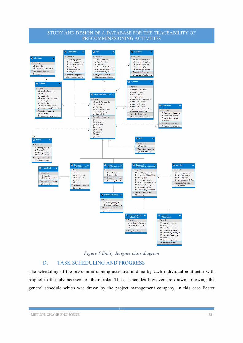
From the above analysis we used Microsoft visual studio to come up with the following entity designer class diagram.
METUGE OKANE ENONGENE 32
STUDY AND DESIGN OF A DATABASE FOR THE TRACEABILITY OF PRECOMMINSSIONING ACTIVITIES
Figure 6 Entity designer class diagram
D. TASK SCHEDULING AND PROGRESS
The scheduling of the pre-commissioning activities is done by each individual contractor with
respect to the advancement of their tasks. These schedules however are drawn following the
general schedule which was drawn by the project management company, in this case Foster
METUGE OKANE ENONGENE 33
STUDY AND DESIGN OF A DATABASE FOR THE TRACEABILITY OF PRECOMMINSSIONING ACTIVITIES
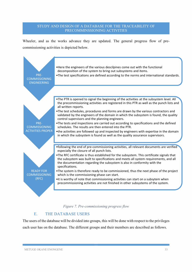
Wheeler, and as the works advance they are updated. The general progress flow of pre-
commissioning activities is depicted below.
Figure 7. Pre-commissioning progress flow
E. THE DATABASE USERS
The users of the database will be divided into groups, this will be done with respect to the privileges
each user has on the database. The different groups and their members are described as follows.
PRE-COMMISSIONING
ENGINEERING
•Here the engineers of the various descilpines come out with the functional decomposition of the system to bring out subsystems and items.
•The test specifications are defined according to the norms and international standards.
PRE-COMMISSIONING
ACTIVITIES PROPER
•The PTR is opened to signal the beginning of the activities at the subsystem level. All the precommissioning activities are registered in this PTR as well as the punch lists and all written reports.
•The test schedules, procedures and forms are drawn by the various contractors and validated by the engineers of the domain in which the subsystem is found, the quality control supervisors and the planning engineers.
•The tests and inspections are carried out according to specifications and the defined schedules. The results are then entered into the PTR.
•the activities are followed up and inspected by engineers with expertise in the domain in which the subsystem is found as well as the quality assurance supervisors.
READY FOR COMMISSIONING
(RFC)
•following the end of pre-commissioning activities, all relevant documents are verified especially the closure of all punch lists.
•The RFC certificate is thus established for the subsystem. This certificate signals that the subsystem was built to specifications and meets all system requirements, and all the documentation regarding the subsystem is also in conformity with the specifications.
•The system is therefore ready to be commissioned, thus the next phase of the project which is the commissioning phase can start.
•it is worthy of note that commissioning activities can start on a subsytem when precommissioning activities are not finished in other subsystems of the system.
METUGE OKANE ENONGENE 34
STUDY AND DESIGN OF A DATABASE FOR THE TRACEABILITY OF PRECOMMINSSIONING ACTIVITIES
Administrators The administrators of the database may include:
o The Head of the project at Foster Wheeler o The Head of the information technology department
o Construction manager QA-QC and Doc control
All the employees of the quality control-quality assurance and document control
departments.
Other users The other users include the employees of the following departments
o Planning department
o Piping supervisors
o Instrumentation supervisors o The construction director
o The head of the project at SONARA o The equipment supervisors o The marketing department ( “ marche des travaux”)
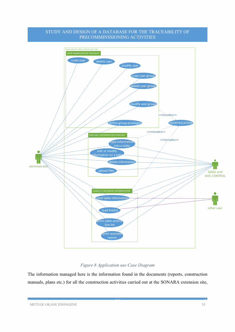
F. DESCRIPTION OF THE EXPECTED FUNCTIONS
The functions that are expected to be realized by the application would be explained using the
following use case diagram.
METUGE OKANE ENONGENE 35
STUDY AND DESIGN OF A DATABASE FOR THE TRACEABILITY OF PRECOMMINSSIONING ACTIVITIES
creat user
creat user group
delete user group
modify user group
type information into a table
delete user
modify user
define group privileges
delete information
edit or modify information on a table
upload files
read table information
print table and/orline list
print scanned report
read linelist
administrator
QAQC and DOC CONTROL
other user
IDENTIFICATION
<<includes>>
<<includes>>
<<includes>>
Figure 8 Application use Case Diagram
The information managed here is the information found in the documents (reports, construction
manuals, plans etc.) for all the construction activities carried out at the SONARA extension site,
METUGE OKANE ENONGENE 36
STUDY AND DESIGN OF A DATABASE FOR THE TRACEABILITY OF PRECOMMINSSIONING ACTIVITIES
as well as the reports to be made during the pre-commissioning activities. These information
includes:
The document numbers or codes: this is a code which is unique to the document and the coding system is defined by the company.
The date of establishment of the document where applicable
The type of document( e.g. radiography report, piping plan) The verdict or conclusion of the activity being reported( accepted or rejected)
Scanned images or pdf files of the documents may be uploaded into the database for consultation, if necessary.
The employee(s) who intervened in the operation being reported The employee(s) who signed the report Etc.
Other information include the Line list which is a table containing most of the pipeline information
gotten from the different tables with respect to the units in which they are found in the refinery.
The line list can only be consulted but not modified since it depends on information which is found
on different tables.
The different use cases can be described as follows:
Management of users (manages users)
The management of users of the database is done exclusively by the administrators of the database,
the different activities that are involved in the management of user are:
The creation of users: this entails attributing a login identifier and a password to a user to enable him/her access to the database
Deletion of users: this involves the removal of a user’s registration information to prevent
access to the database Modification of users: this may involve the modification of the user’s identification
credentials. The attribution of groups to users: Defining user group privileges
Adding user groups Deleting user groups Modifying user groups
Management of information
The management of information use case entails:
METUGE OKANE ENONGENE 37
STUDY AND DESIGN OF A DATABASE FOR THE TRACEABILITY OF PRECOMMINSSIONING ACTIVITIES
Typing information into the database Editing or modifying information which is already present on the database
Deleting database information Uploading files to the database
Consultation of information
The consults information use case has as activities:
Reading information found on the different tables
Reading the information found on the line lists Consulting scanned copies of reports
Printing tables into a pdf file or excel file Printing scanned reports.
G. TECHNICAL REQUIREMENTS
As regards the technical requirements of the database to be developed, we will examine certain
points with respect to the architecture and ergonomics. The first requirement we will examine is
the user interface (UI)
1. THE USER INTERFACE
Thought was then given to the method of display of information and two platforms were
considered as regards the user interface, a web platform and a desktop platform. The following is
the analysis done to come up with the decision as regards the platform to be used.
Table 3 Table comparing a web and Desktop interface with respect to the needs of the company
Property Web interface Desktop interface
installation The database application is installed only once and hosted on a server, all the users can thus access the database information using their browsers
Independent on the user’s operating system.
Has little hardware constraints thus data can be accessed from a computer, smartphone or tablet if it has a browser
The database is first hosted on the server and then the user interface application installed on all the individual machines.
Mostly designed differently for different operating systems.
Has constraints as regards the hardware being used to access the data
METUGE OKANE ENONGENE 38
STUDY AND DESIGN OF A DATABASE FOR THE TRACEABILITY OF PRECOMMINSSIONING ACTIVITIES
maintenance Updating or upgrading is done only on
the server on which it was installed
All the individual installations need
to be updated or upgraded
Ease of use The information can be accessed from
anywhere using the internet
Use of the application is confined
to a physical location
security Exposed to high security risks due to its
connectivity with the internet and its
flexibility with respect to the computer
and mobile platforms
Relatively lower vulnerability to
security threats
connectivity Due to the centralized data base system both need a network for data access
thus performance and speed will depend not only on the database, but on the
connection as well.
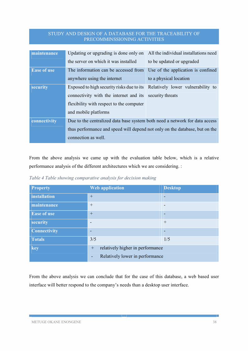
From the above analysis we came up with the evaluation table below, which is a relative
performance analysis of the different architectures which we are considering. :
Table 4 Table showing comparative analysis for decision making
Property Web application Desktop
installation + -
maintenance + -
Ease of use + -
security - +
Connectivity - -
Totals 3/5 1/5
key + relatively higher in performance
- Relatively lower in performance
From the above analysis we can conclude that for the case of this database, a web based user
interface will better respond to the company’s needs than a desktop user interface.
METUGE OKANE ENONGENE 39
STUDY AND DESIGN OF A DATABASE FOR THE TRACEABILITY OF PRECOMMINSSIONING ACTIVITIES
2. DATA SECURITY
In order to conserve data integrity and safety it is imperative that access to the database be
restricted to the users defined above, for that to be made possible it is important to put in place a
good security system that not only restricts the use of the database by unregistered personnel but
also restricts access to unauthorized operations on the data found in the database. For that, the
security system will be designed as follows;
The users of the database would be divided into groups, starting with the ones mentioned above (i.e. ADMINISTRATORS, QAQC AND DOC CONTROL and OTHER USERS). Other groups can be added as need arises.
Each group will have predefined privileges, which determine what they can and cannot do
on the database.
Each user of the database will be registered by the administrator and an account opened for him/her.
Every user will be attributed to a group, and a unique username and password created for the user. It is important that the username uniquely identifies a given user of the database.
Access to the database should be restricted only to the registered users of the database, and
that with the use of a login window as the user opens the database, where a username and password is demanded
The user should have three trial attempts to enter his username and password, failure to
enter the correct login credentials will result in the account being locked. If a user account is locked, only the administrator has clearance to unlock it
There should be a possibility of changing a user’s username and password, and only the administrator can do that.
METUGE OKANE ENONGENE 40
STUDY AND DESIGN OF A DATABASE FOR THE TRACEABILITY OF PRECOMMINSSIONING ACTIVITIES
III. FUNCTIONING OF THE APPLICATION
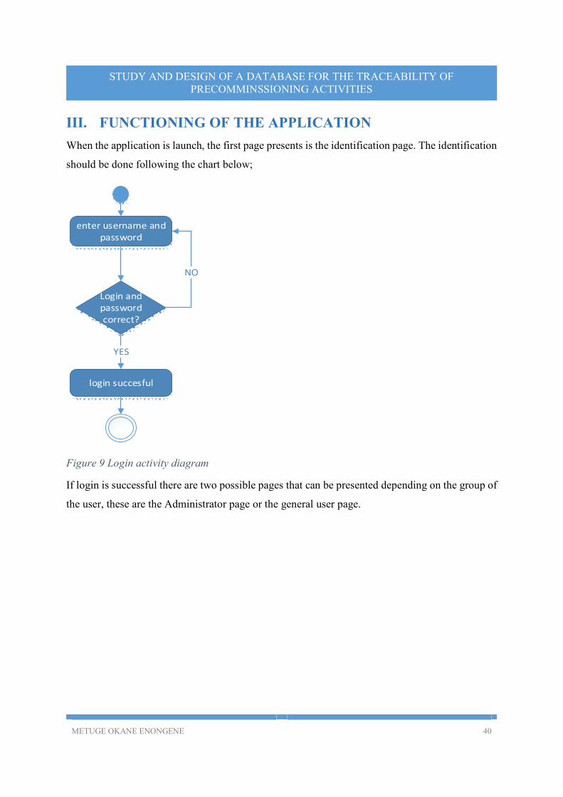
When the application is launch, the first page presents is the identification page. The identification
should be done following the chart below;
Login and password correct?
enter username and password
login succesful
YES
NO
Figure 9 Login activity diagram
If login is successful there are two possible pages that can be presented depending on the group of
the user, these are the Administrator page or the general user page.
METUGE OKANE ENONGENE 41
STUDY AND DESIGN OF A DATABASE FOR THE TRACEABILITY OF PRECOMMINSSIONING ACTIVITIES
A. ADMINISTRATOR’S INTERFACE
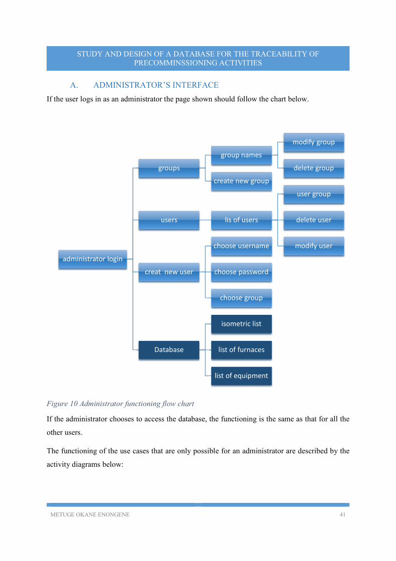
If the user logs in as an administrator the page shown should follow the chart below.
Figure 10 Administrator functioning flow chart
If the administrator chooses to access the database, the functioning is the same as that for all the
other users.
The functioning of the use cases that are only possible for an administrator are described by the
activity diagrams below:
administrator login
groups
group names
modify group
delete group
create new group
users lis of users
user group
delete user
modify user
creat new user
choose username
choose password
choose group
Database
isometric list
list of furnaces
list of equipment
METUGE OKANE ENONGENE 42
STUDY AND DESIGN OF A DATABASE FOR THE TRACEABILITY OF PRECOMMINSSIONING ACTIVITIES
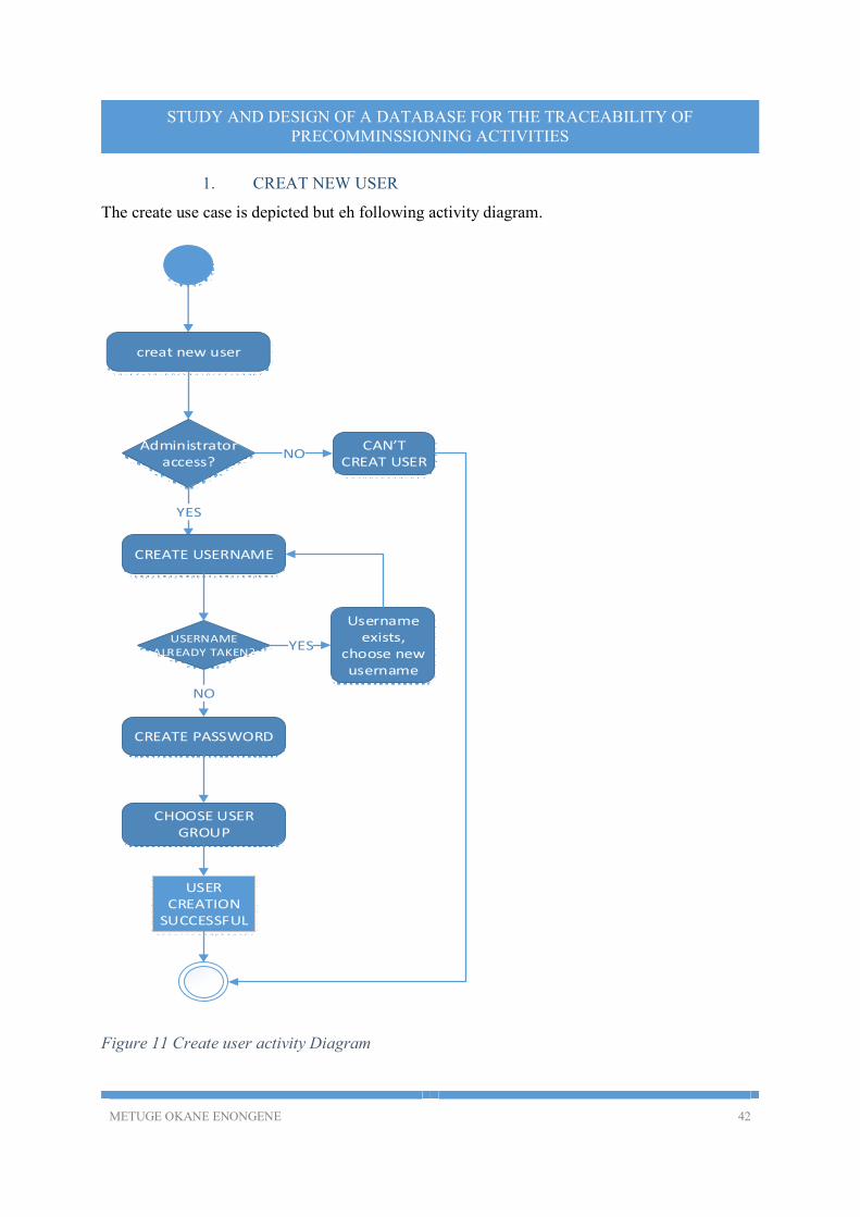
1. CREAT NEW USER
The create use case is depicted but eh following activity diagram.
creat new user
Administrator access?
YES
CREATE USERNAME
CREATE PASSWORD
USERNAME ALREADY TAKEN?
CHOOSE USER GROUP
USER CREATION
SUCCESSFUL
NO
NO
YES
Username exists,
choose new username
CAN’T CREAT USER
Figure 11 Create user activity Diagram
METUGE OKANE ENONGENE 43
STUDY AND DESIGN OF A DATABASE FOR THE TRACEABILITY OF PRECOMMINSSIONING ACTIVITIES
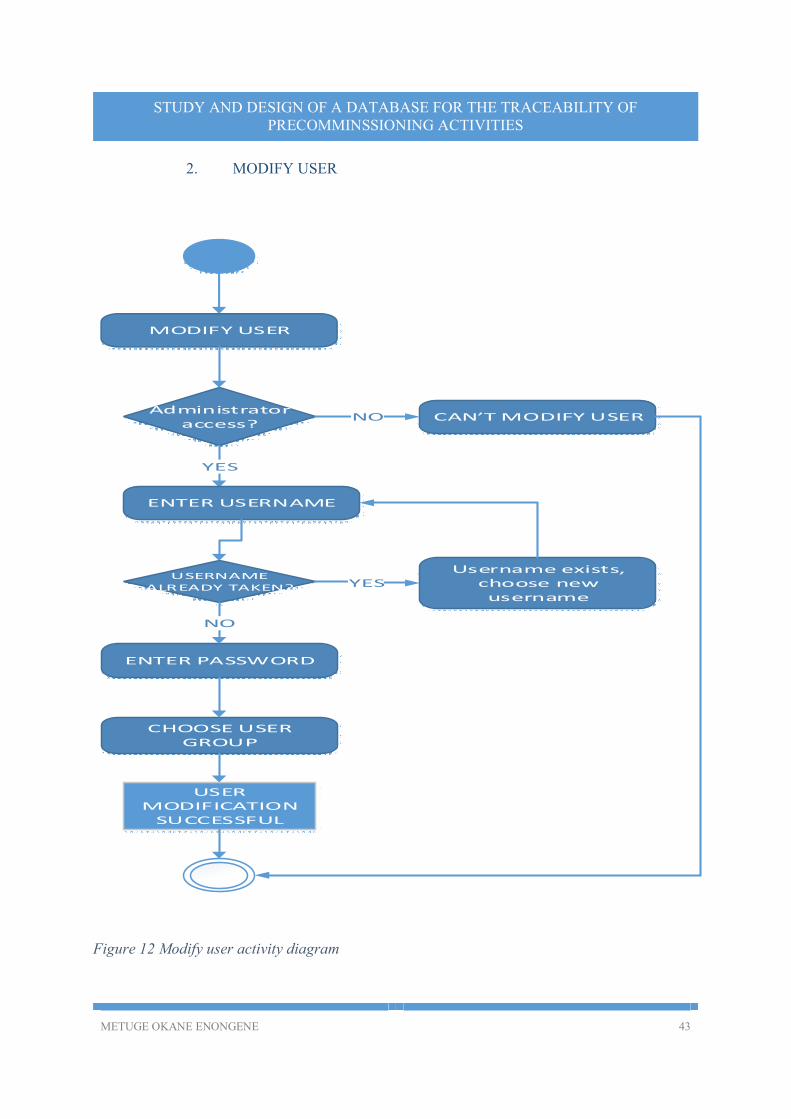
2. MODIFY USER
MODIFY USER
Administrator access?
YES
ENTER USERNAME
ENTER PASSWORD
USERNAME ALREADY TAKEN?
CHOOSE USER GROUP
USER MODIFICATION
SUCCESSFUL
YES
NO
CAN’T MODIFY USERNO
Username exists, choose new username
Figure 12 Modify user activity diagram
METUGE OKANE ENONGENE 44
STUDY AND DESIGN OF A DATABASE FOR THE TRACEABILITY OF PRECOMMINSSIONING ACTIVITIES
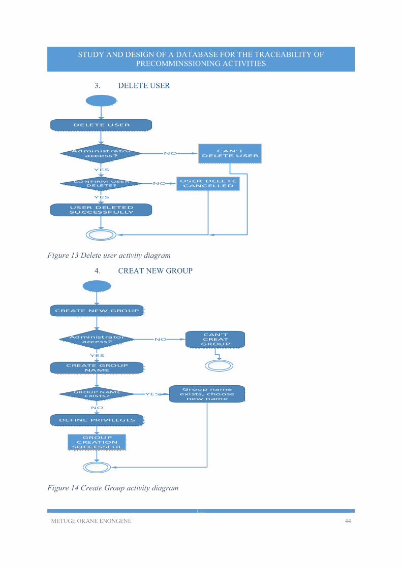
3. DELETE USER
DELETE USER
Administrator access?
CAN’T DELETE USER
YES
USER DELETED SUCCESSFULLY
CONFIRM USER DELETE?
USER DELETE CANCELLED
NO
NO
YES
Figure 13 Delete user activity diagram
4. CREAT NEW GROUP
CREATE NEW GROUP
Administrator access?
CREATE GROUP NAME
DEFINE PRIVILEGES
GROUP NAME EXISTS?
GROUP CREATION
SUCCESSFUL
NO
YES
NO
YES
YESGroup name
exists, choose new name
CAN’T CREAT GROUP
Figure 14 Create Group activity diagram
METUGE OKANE ENONGENE 45
STUDY AND DESIGN OF A DATABASE FOR THE TRACEABILITY OF PRECOMMINSSIONING ACTIVITIES
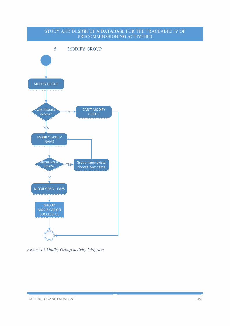
5. MODIFY GROUP
MODIFY GROUP
Administrator access?
YES
MODIFY GROUP NAME
MODIFY PRIVILEGES
GROUP NAME EXISTS?
GROUP MODIFICATION
SUCCESSFUL
CAN’T MODIFY GROUP
NO
YESGroup name exists, choose new name
NO
Figure 15 Modify Group activity Diagram
METUGE OKANE ENONGENE 46
STUDY AND DESIGN OF A DATABASE FOR THE TRACEABILITY OF PRECOMMINSSIONING ACTIVITIES
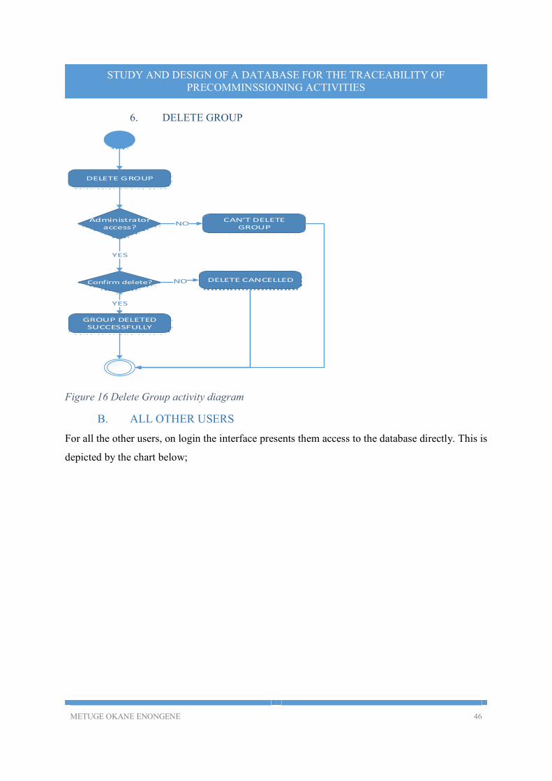
6. DELETE GROUP
DELETE GROUP
Administrator access?
YES
Confirm delete? DELETE CANCELLED
GROUP DELETED SUCCESSFULLY
YES
NO
NOCAN’T DELETE
GROUP
Figure 16 Delete Group activity diagram
B. ALL OTHER USERS
For all the other users, on login the interface presents them access to the database directly. This is
depicted by the chart below;
METUGE OKANE ENONGENE 47
STUDY AND DESIGN OF A DATABASE FOR THE TRACEABILITY OF PRECOMMINSSIONING ACTIVITIES
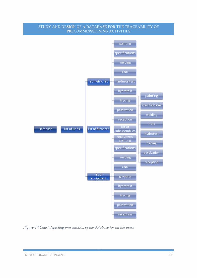
Figure 17 Chart depicting presentation of the database for all the users
Database list of units
Isometric list
painting
specifications
welding
CND
hardness test
hydrotest
tracing
passivation
reception
list of furnaceslist of
subassemblies
painting
specifications
welding
CND
hydrotest
tracing
passivation
reception
list of equipment
equipment painting
specifications
welding
CND
grouting
hydrotest
tracing
passivation
reception
METUGE OKANE ENONGENE 48
STUDY AND DESIGN OF A DATABASE FOR THE TRACEABILITY OF PRECOMMINSSIONING ACTIVITIES
IV. POSSIBLE IMPACT OF THE DATABASE
A. TECHNICAL IMPACT
The technical impact of this project will be analyzed mainly the possible gain in time.
The study of the possible impact of this project on the gain in time during the pre-commissioning
activities will be modelled with the use of the verification and validation of a report called the ISO
summary list.
To verify and validate the above mentioned document, each column has information to be verified
on a separate report. The columns of the ISO summary list and the reports to be consulted for the
validation of the column are presented on table 5 below.
The sample ISO summary list I used for analysis had 20 columns and 20 rows (maximum
number of rows that can be present on a report).
From the quality inspector’s experience, it takes about 5 minutes to verify the ISO
summary list information on a given report.
The best case scenario with respect to time consumption is that no NDT tests are referenced
on the list.
The worst case scenario is that all the cells of the list are filled.
Calculations will also be based on the fact that a working day has 8 hours, but only 7 hours
are effectively used for work.
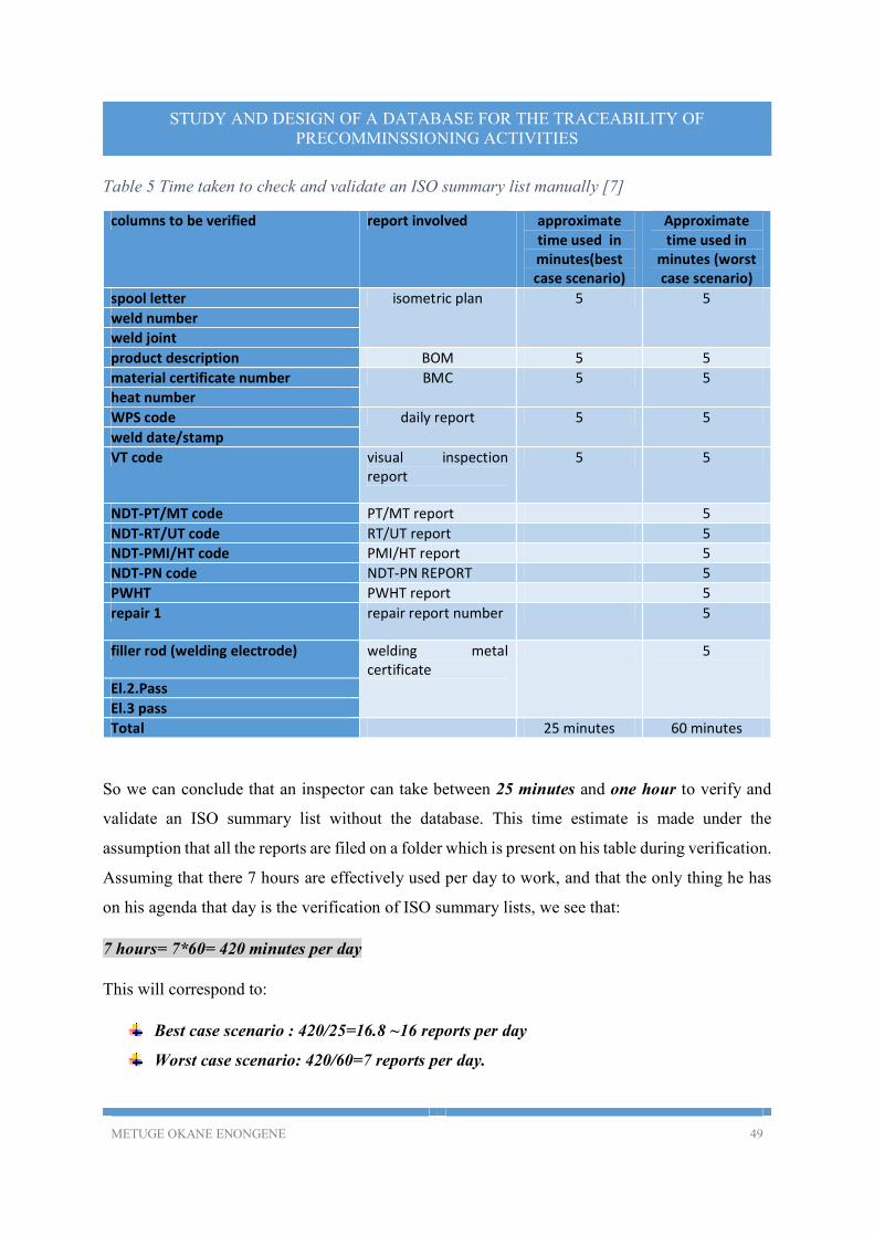
METUGE OKANE ENONGENE 49
STUDY AND DESIGN OF A DATABASE FOR THE TRACEABILITY OF PRECOMMINSSIONING ACTIVITIES
Table 5 Time taken to check and validate an ISO summary list manually [7]
columns to be verified report involved approximate time used in minutes(best case scenario)
Approximate time used in
minutes (worst case scenario)
spool letter isometric plan 5 5
weld number
weld joint
product description BOM 5 5
material certificate number BMC 5 5
heat number
WPS code daily report 5 5
weld date/stamp
VT code visual inspection report
5 5
NDT-PT/MT code PT/MT report 5
NDT-RT/UT code RT/UT report 5
NDT-PMI/HT code PMI/HT report 5
NDT-PN code NDT-PN REPORT 5
PWHT PWHT report 5
repair 1 repair report number 5
filler rod (welding electrode) welding metal certificate
5
El.2.Pass
El.3 pass
Total 25 minutes 60 minutes
So we can conclude that an inspector can take between 25 minutes and one hour to verify and
validate an ISO summary list without the database. This time estimate is made under the
assumption that all the reports are filed on a folder which is present on his table during verification.
Assuming that there 7 hours are effectively used per day to work, and that the only thing he has
on his agenda that day is the verification of ISO summary lists, we see that:
7 hours= 7*60= 420 minutes per day
This will correspond to:
Best case scenario : 420/25=16.8 ~16 reports per day
Worst case scenario: 420/60=7 reports per day.
METUGE OKANE ENONGENE 50
STUDY AND DESIGN OF A DATABASE FOR THE TRACEABILITY OF PRECOMMINSSIONING ACTIVITIES
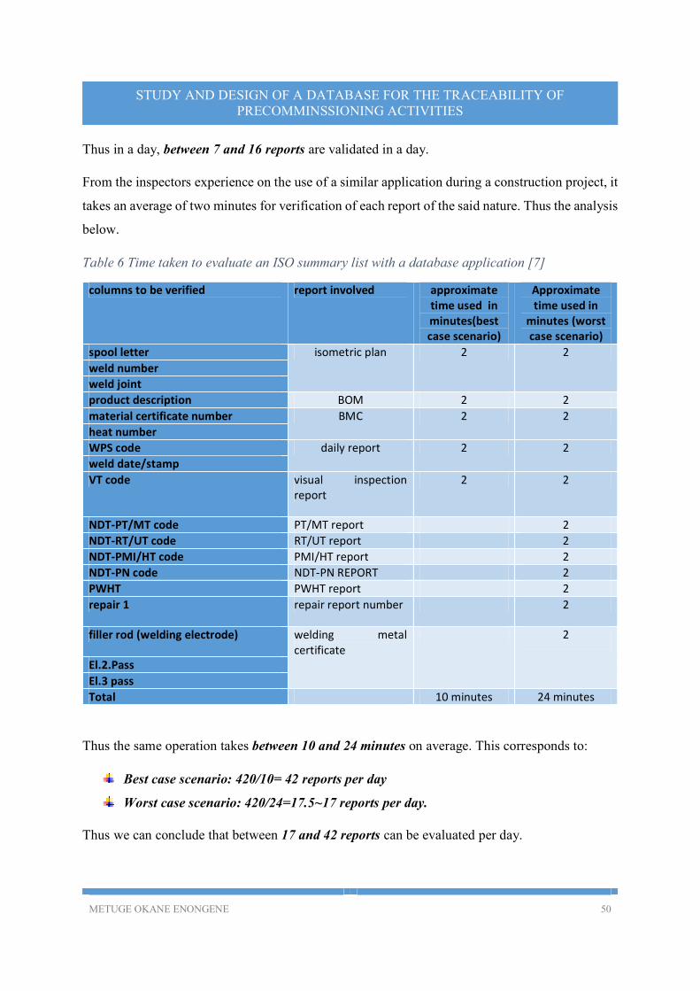
Thus in a day, between 7 and 16 reports are validated in a day.
From the inspectors experience on the use of a similar application during a construction project, it
takes an average of two minutes for verification of each report of the said nature. Thus the analysis
below.
Table 6 Time taken to evaluate an ISO summary list with a database application [7]
columns to be verified report involved approximate time used in minutes(best case scenario)
Approximate time used in
minutes (worst case scenario)
spool letter isometric plan 2 2
weld number
weld joint
product description BOM 2 2
material certificate number BMC 2 2
heat number
WPS code daily report 2 2
weld date/stamp
VT code visual inspection report
2 2
NDT-PT/MT code PT/MT report 2
NDT-RT/UT code RT/UT report 2
NDT-PMI/HT code PMI/HT report 2
NDT-PN code NDT-PN REPORT 2
PWHT PWHT report 2
repair 1 repair report number 2
filler rod (welding electrode) welding metal certificate
2
El.2.Pass
El.3 pass
Total 10 minutes 24 minutes
Thus the same operation takes between 10 and 24 minutes on average. This corresponds to:
Best case scenario: 420/10= 42 reports per day
Worst case scenario: 420/24=17.5~17 reports per day.
Thus we can conclude that between 17 and 42 reports can be evaluated per day.

METUGE OKANE ENONGENE 51
STUDY AND DESIGN OF A DATABASE FOR THE TRACEABILITY OF PRECOMMINSSIONING ACTIVITIES
a) Gain in time if database is used
The gain in time due to the use of the database can be evaluated as follows:
���� ���� �������� = ���� ���� ������� �������� − ���� ���� ���� ��������
From the tables above, this gives: 25 − 10 = 15 minutes
����� ���� �������� = ����� ���� ������� �������� − ����� ���� ���� ��������
= 60 − 24 = 36 �������
We can conclude thus that the time saved to check and validate an ISO summary list is between
15 and 34 minutes.
b) Gain in Work done if database is used
���� ���� �������� = ���� ���� ���� �������� − ���� ���� ������� ��������
= 42 − 16 = 26 �������
����� ���� �������� = ����� ���� ���� �������� − ����� ���� ������� ��������
= 17 − 7 = 10 ������� ��� ���.
From the above analysis we see that between 10 and 26 additional reports can be validated in a
day if the data base is developed and implemented.
From the above analysis we can conclude that the database project, if developed and implemented,
will save considerable time during document control for pre-commissioning activities. Although
the modelling was done only for one type of report, it will be valid for all the other types as well.
B. FINANCIAL IMPACT
Financially, given that the application is for local use and not for a commercial purpose, there is
no direct financial impact on the company. The financial impact of the application on the company
is indirect, and that will be evaluated as a function of the gain in time.
From IV-A-(a) above we saw that the time saved in the verification and validation of an ISO
summary list is between 15 and 34 minutes.
If we have � reports to be verified and validated during pre-commissioning activities, then the
time gain can be modelled as 15� ≤ ���� ������(�� �������) ≤ 34�
METUGE OKANE ENONGENE 52
STUDY AND DESIGN OF A DATABASE FOR THE TRACEABILITY OF PRECOMMINSSIONING ACTIVITIES
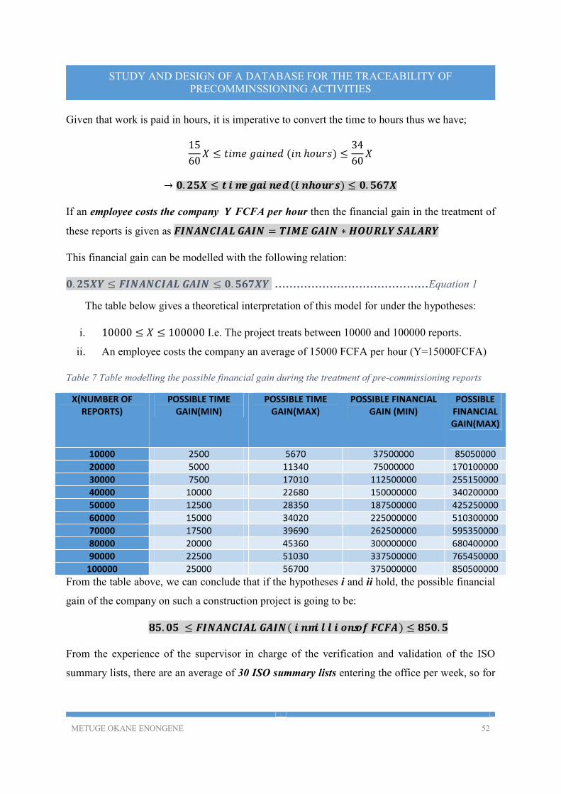
Given that work is paid in hours, it is imperative to convert the time to hours thus we have;
15
60� ≤ ���� ������ (�� ℎ����) ≤
34
60�
→ �. ��� ≤ ���� ������ (�� �����) ≤ �. ����
If an employee costs the company � FCFA per hour then the financial gain in the treatment of
these reports is given as ��������� ���� = ���� ���� ∗������ ������
This financial gain can be modelled with the following relation:
�. ���� ≤ ��������� ���� ≤ �. ����� ……………………………………Equation 1
The table below gives a theoretical interpretation of this model for under the hypotheses:
i. 10000 ≤ � ≤ 100000 I.e. The project treats between 10000 and 100000 reports.
ii. An employee costs the company an average of 15000 FCFA per hour (Y=15000FCFA)
Table 7 Table modelling the possible financial gain during the treatment of pre-commissioning reports
X(NUMBER OF REPORTS)
POSSIBLE TIME GAIN(MIN)
POSSIBLE TIME GAIN(MAX)
POSSIBLE FINANCIAL GAIN (MIN)
POSSIBLE FINANCIAL GAIN(MAX)
10000 2500 5670 37500000 85050000
20000 5000 11340 75000000 170100000
30000 7500 17010 112500000 255150000
40000 10000 22680 150000000 340200000
50000 12500 28350 187500000 425250000
60000 15000 34020 225000000 510300000
70000 17500 39690 262500000 595350000
80000 20000 45360 300000000 680400000
90000 22500 51030 337500000 765450000
100000 25000 56700 375000000 850500000
From the table above, we can conclude that if the hypotheses i and ii hold, the possible financial
gain of the company on such a construction project is going to be:
��. �� ≤ ��������� ����( �� �������� �� ����) ≤ ���. �
From the experience of the supervisor in charge of the verification and validation of the ISO
summary lists, there are an average of 30 ISO summary lists entering the office per week, so for
METUGE OKANE ENONGENE 53
STUDY AND DESIGN OF A DATABASE FOR THE TRACEABILITY OF PRECOMMINSSIONING ACTIVITIES
the 2 years since these reports started being emitted, let us consider the following hypotheses for
the financial gain that could have been realized if such a system was put in place;
Considering 22 working days per month
4 weeks per month
10 public holidays in a year which fall on working days( 2 weeks without work)
12 months a year(11.5 months effective work)
�� ����� ��� ���� ∗� ����� ��� ����ℎ = ��� ��� ������� ����� ��� ����ℎ
��� ����� ��� ����ℎ ∗��. � ����ℎ� = ���� ����� ��� ����
���� ����� ��� ���� ∗ � ����� = ���� �������
We notice thus that an average of 2760 ISO summary lists are treated in two years.
Taking hypotheses i and ii and Equation 1 above into consideration, we have that;
2760 ∗15000 ∗ 0.25 ≤ ��������� ���� ≤ 2760 ∗15000 ∗0.567
The gain is thus evaluated at:
��. �� ≤ ��������� ����(�� �������� �� ����) ≤ ��. ���
Given the financial gain above which is evaluated only on one type of report, it is clear that if all
the reports emitted are treated with the database, the gains will be enormous.
C. ORGANIZATIONAL IMPACT
The organizational impact that such a database application can have on the smooth functioning of
pre-commissioning activities during such a construction project can be discussed in two sub-topics.
1. IMPACT ON PLANNING
During the construction process, access to a database of such nature will give the construction
director and Engineers up to date information on all the activities and their level of realization.
This will permit the planning technicians and engineers to;
Know the tasks that have been realized and the approximate duration of realization
METUGE OKANE ENONGENE 54
STUDY AND DESIGN OF A DATABASE FOR THE TRACEABILITY OF PRECOMMINSSIONING ACTIVITIES
Study the difference between the time allocated for an operation and the time used so as to
better manage deadlines.
With information from the application, planning of future tasks can be made as past
planning information is available.
Information from the database will permit the company to decide with better accuracy the time
when the commissioning activities should be launched.
2. IMPACT ON QUALITY CONTROL
As regards quality control, the database application will amongst other impacts:
Ease the control and validation of quality reports,
Ease the programming of inspection visits as well as reception visits
Ease the traceability of information during and after the control
Ease the justification of decisions during meetings.
METUGE OKANE ENONGENE 55
STUDY AND DESIGN OF A DATABASE FOR THE TRACEABILITY OF PRECOMMINSSIONING ACTIVITIES
CONCLUSION AND PERSPECTIVES
The theme we worked on required us to study and design a database to manage the information
regarding traceability gotten from pre-commissioning activities, the study was really interesting as
I got to learn a lot about pre-commissioning, especially the involvement of quality control and
assurance. At the end of the study, we proposed a model for the database, how the user can access
the database (using a web interface), how the database should be secured, and the general behavior
of some use cases.
As perspective thus we will propose that:
The database application be developed and implemented as it will really facilitate pre-
commissioning activities,
Studies should be done and other pre-commissioning activities which were not included in
the scope of this study be added to make the application more useful and thus go an extra
mile to facilitate pre-commissioning, both for the case of the construction of a refinery and
other construction activities,
The database should be extended to cover commissioning activities as well or a different
database can be designed in this effect.
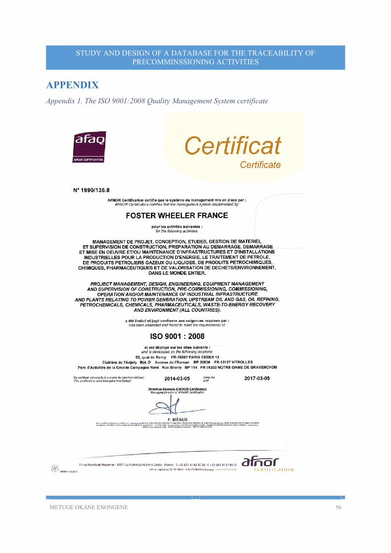
METUGE OKANE ENONGENE 56
STUDY AND DESIGN OF A DATABASE FOR THE TRACEABILITY OF PRECOMMINSSIONING ACTIVITIES
APPENDIX
Appendix 1. The ISO 9001:2008 Quality Management System certificate
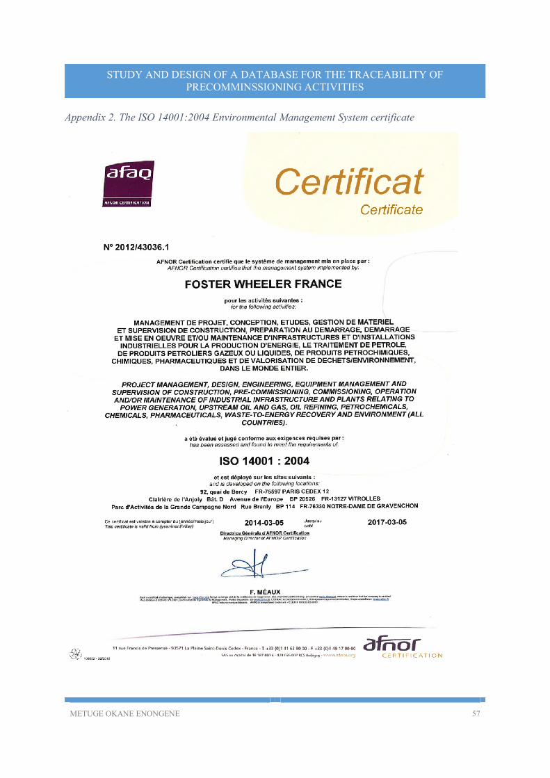
METUGE OKANE ENONGENE 57
STUDY AND DESIGN OF A DATABASE FOR THE TRACEABILITY OF PRECOMMINSSIONING ACTIVITIES
Appendix 2. The ISO 14001:2004 Environmental Management System certificate

METUGE OKANE ENONGENE 58
STUDY AND DESIGN OF A DATABASE FOR THE TRACEABILITY OF PRECOMMINSSIONING ACTIVITIES
Appendix 3. The OHSAS 18001:2007-Occupational health and safety Management System certificate
METUGE OKANE ENONGENE 59
STUDY AND DESIGN OF A DATABASE FOR THE TRACEABILITY OF PRECOMMINSSIONING ACTIVITIES
REFERENCES
[1]. Foster Wheeler AG. History. Foster Wheeler website. [Online] july 2014.
http://fwc.com/Who-We-Are/History.aspx.
[2]. Foster Wheeler Cameroon. Presentation of Foster Wheeler. 2013.
[3]. TOTAL. General specification GS EP EXP 101, Pre-commissioning and commissioning
specifications. 2012.
[4]. Foster Wheeler France. PLAN D'INSPECTION ET D'ESSAI-TUYAUTERIE( Doc Number
1CD1317A-SBC03-QL-002). SEPTEMBER 2012.
[5]. FOSTER WHEELER FRANCE. Plan d'inspection et d'essai-Fours_55F-01/02/03/04(Doc
Number 1CD1317A-SBC03-QL-006). september 2012.
[6]. Foster Wheeler France. Plan d'inspection et d'essai-Equipements(Doc Number 1CD1317A-
SBC03-QL-004). Limbe, South West Region, Cameroon : s.n., September 2012.
[7]. SIMI AMAL. ISO Summary List ( No 1.546.2/0971). Limbe-Cameroon : s.n., 2014.
[8]. Roques, Pascal. UML 2 Par la pratique-Etudes de cas et exercises corriges. Paris :
EYROLLES, 2006.
[9]. Soutou, Christian. UML 2 pour les bases de donnees. Paris : EYROLLES, 2002.
[10]. Batchakui, Dr. Cours UML. Yaounde, Central Region, Cameroon : s.n., 2013.
[11]. smith, Jeff. Desktop applications Vs web applications. Street Directory. [Online]
http://www.streetdirectory.com/travel_guide/114448/programming/desktop_applications_vs_we
b_applications.html.
[12]. Bychkov, Dmitriy. Desktop vs. Web Applications: A Deeper Look and Comparison. SEGUE
TECHNOLOGIES. [Online] http://www.seguetech.com/blog/2013/06/07/desktop-vs-web-
applications-deeper-comparison.