internet of things-based smart street system
TRANSCRIPT

ISSN: 2237-0722
Vol. 11 No. 4 (2021)
Received: 12.08.2021 – Accepted: 10.09.2021
5577
Internet of Things-based Smart Street System
Chandla Ellis1; Tirumala Raju Vineetha2; Segu Sravana Keerthi3; S.P. Kalpana4; R. Roshni Karen5
1Associate Professor/EEE, R.M.K. Engineering College, Chennai, Tamil Nadu, India. [email protected]
2UG Student, R.M.K. Engineering College, Chennai, Tamil Nadu, India. [email protected]
3UG Student, R.M.K. Engineering College, Chennai, Tamil Nadu, India. [email protected]
4UG Student, R.M.K. Engineering College, Chennai, Tamil Nadu, India. [email protected]
5UG Student, R.M.K. Engineering College, Chennai, Tamil Nadu, India. [email protected]
Abstract
Enormous amount of electrical energy is consumed in urban areas by means of street lights.
Currently, the street lights are turned on and off manually which will lead to wastage of electrical
energy. Due to inadequate dimming and low efficiency of lights, current is being wasted. The main
aim of this smart LED system is to create a street light which will behave according to its
surrounding. This LED will turn on automatically during dark time and off during bright time with
the help of LDR. It will remain dim when there is no one near the light and turns on bright when
people pass by it. By doing this, huge amount of energy is being saved. Though solar energy is
efficient, it can’t work during rainy season. Thus, piezoelectric sensor is a good replacement of it. It
converts the pressure that applied on it to electrical energy. This sensor is fixed in the road which
will convert the pressure applied to it by the vehicles to electrical energy which can be utilized by the
LEDs. Finally, this system aims to present an overview of a profitable and green solution to the
energy consumption problem imposed by street lighting.
Key-words: Arduino Uno R3, IR (Infrared) Motion Sensor, LDR (Light Dependent Resistor), LEDs
(Light Emitting Diode), Resistor, Piezoelectric Sensor, Open CV, Light Intensity Control.
1. Introduction
There is a huge need for the wireless electrical energy which encouraged the interest towards
piezoelectric energy harvesting, or the conversion of vibration into electrical energy [1]. Piezoelectric
ISSN: 2237-0722
Vol. 11 No. 4 (2021)
Received: 12.08.2021 – Accepted: 10.09.2021
5578
transducers, has the inheritance of electromechanical coupling and it has high power density
compared to electromagnetic transducers and electrostatic transducers, has a wide range of
exploration to generate energy from vibration. Many researchers developed novel applications for
piezoelectric energy harvesting in the past decades [2]. Kinetic energy is used by wide range of
applications ranging from implanted devices and electronic devices to mobile electronics and wireless
node which is self-powered. The use of piezoelectric energy is a great improvement when it comes to
kinetic energy harvesting [3]. At present, there are three types of piezoelectric devices which is
investigated and tested for determining each of their ability to transform the vibration into electrical
energy and their capacity to recharge discharged batteries. That three types of piezoelectric devices
are, monolithic piezoceramic material lead-zirconate-titanate (PZT), the bimorph Quick Pack (QP),
actuator and Macro Fiber Composite (MFC). The most efficient device among this is piezoceramic
material lead-zirconate-titanate (PZT) [4].
Automatic control system of street lights, whenever it is required, increases the efficiency of
street lights. The pressure applied by the vehicles in the road is converted to electrical energy [5]. The
kinetic energy obtained from the piezoelectric energy can be used to power piezoelectric compression
[6]. By using piezoelectric ceramics, vivo electric energy can be generated which can be used for
orthopedic implants. Since microprocessors used for orthopedic implants require much energy,
piezoelectric ceramic is a good replacement [7]. Lighting Automatic Control System (LACS) is a
Wireless Sensor Networks (WSN) design used for the applications that uses conservation of energy
such as light control [8].
In order to control and monitor street lights, the lighting pole controller is used based on
Wireless Sensor Network [9]. According to the latitude, longitude and seasonal variation, reasonable
adjustments in the street lights can be made for efficient automation. Automation of street lights can
be controlled according to the sunrise, sunset and light intensity algorithm [10]. There are many kinds
of sensor for sensing the environment, but, multi-sensor exhibition can logically control automated
street light system. Based on the degree of illumination control fixed time, street lights can be
controlled by pre-installing time [11]. AT89S52, a single-chip microcomputer, is a combination of
digital clock, a timer, a Liquid Crystal Display (LCD), a statistic of traffic flowing magnitude, a
photosensitive induction, an infrared control, alarm function, a time cut-out function, an automatic
control pattern by which automation of street lights can be more efficient [12]. The combination of
automation, Power Line Communication and Web access provide a complete access for efficient
automation of street lights [13]. Use of multiple sensors, LEDs with ZigBee protocol helps in
providing energy efficient control of street lights from remote areas. Unique functions like sensing
ISSN: 2237-0722
Vol. 11 No. 4 (2021)
Received: 12.08.2021 – Accepted: 10.09.2021
5579
frequency of persons passing by and using sensing devices like LDR and gas sensors also increases
the efficiency of automation [14].
Street lights can be turned on when vehicle passes by and later turned off with the help of PIC
microcontroller. Automatic time cut-out and an automatic control pattern can also be included for the
electricity conservation [15]. Solar panel is an active form of solar energy. Solar Cells or photovoltaic
cells are arranged in a grid-like pattern on the surface of solar panel. This, changes the direction of
solar panel according to the intensity of the sunlight with the help of passive trackers and thus gain
natural energy [16]. A ZigBee module with the help of graphical user interface (GUI) can be used for
the detection of faulty lights and control of it. An intelligent automation system with decisions like
ON/OFF/DIMMING gives more control towards street light automation [17]. High luminous
efficiency, small size, lightweight and longer lifetime are the advantages of high frequency electronic
ballast for high-intensity and efficient discharge lamps [18]. Nigerian households, which were poorly
lit by kerosene wick lamp are adapting LED based lamps. But, since the power supply to LEDs are
not regulated there is illumination losses. Thus regulated LED lamps can be replaced which shows
more stability [19]. Smart street light system can be implemented by sensing an approaching vehicle
towards the street light. This is achieved by using IR sensor which turns on light when vehicle passes
by and using LDR for turning on light during night times. Thus, a lot of energy is saved [20].
This paper is dived into five segments. Segment II explains about the components and its
specifications that are involved in this paper. Segment III explains the functioning of the project.
Segment IV explains about the outcomes of the system. Segment V gives the conclusion about the
whole paper.
2. System Parameters
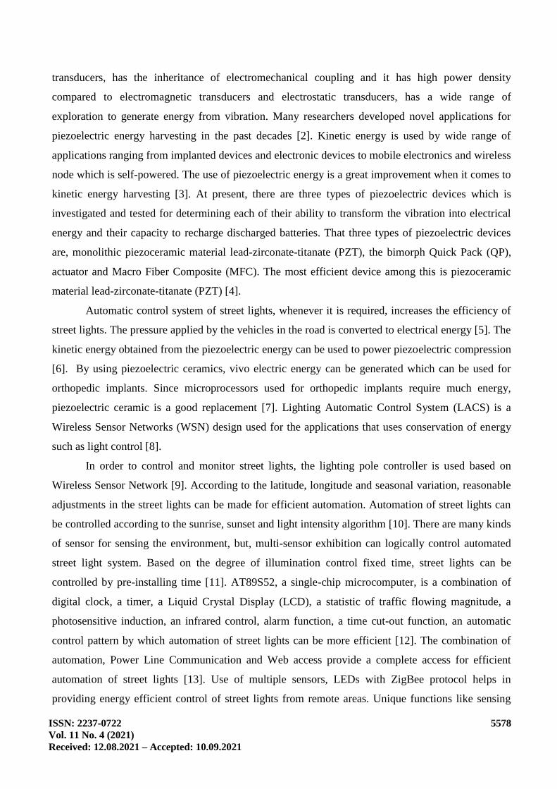
Arduino uno is an 8-bit AT mega 328p microcontroller. It consists of 14 digital input-output
pins. With input voltage of 7-12 volts and with operating voltage of 5 volts. In our project, Arduino
plays a major role in controlling inputs and outputs. Here, we have connected the IR sensors to the
analog pins of Arduino by which it will be managing the output of the Led lights. Generally, an
Arduino can be powered by USB cable by the 9 volts battery. Here, the output voltage we get from
piezoelectric disc is 13 volts in these 9 volts can be used by the Arduino.
ISSN: 2237-0722
Vol. 11 No. 4 (2021)
Received: 12.08.2021 – Accepted: 10.09.2021
5580
Table 1 - Arduino Specifications
MCU ATmega328P
Flash Memory 32 KB
Clock Speed 16 MHz
Digital IO Pins 24
Analog Input Pins 6
Fig. 1 - Arduino UNO
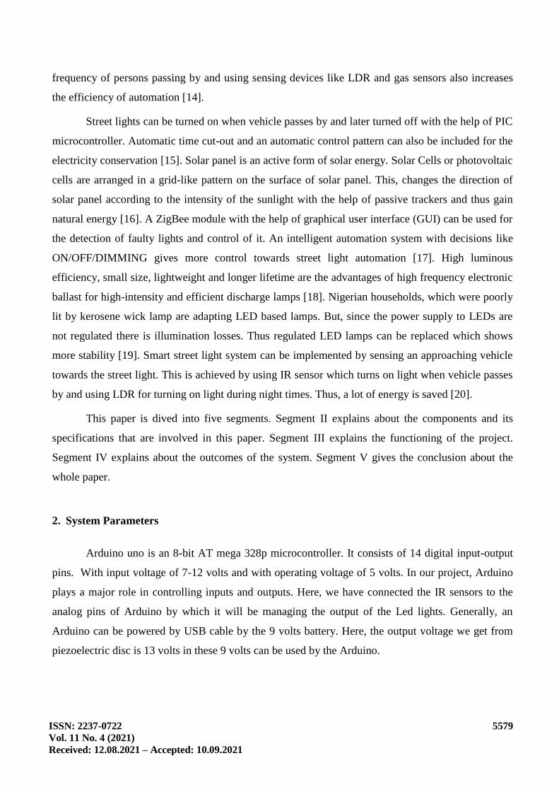
Here piezoelectricity is generated by applying the pressure to the material.it is based on
piezoelectric effect which explains that whenever mechanical pressure is applied to quartz crystal
then it will be generating the electric loads on the quartz crystal. Here the load generated will depend
upon mechanical force applied to it. the piezoelectric transducer is sensitive hence it operates as a
sensor and taken to accelerometer based on frequency of the reaction. Generally, 2 piezoelectric
transducer pads will generate an output voltage of 3.5-4 volts.
Here in our project, we had used the 8 transducer pads. So, we get maximum output voltage as
3.5x4=14volts. i.e. So it takes like 4 hours to charge a battery.
Fig. 2 - Piezoelectric Transducer
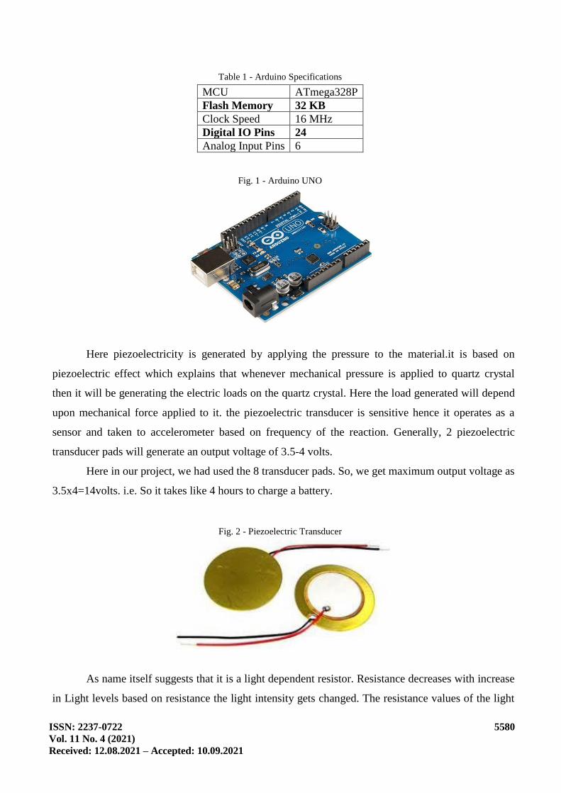
As name itself suggests that it is a light dependent resistor. Resistance decreases with increase
in Light levels based on resistance the light intensity gets changed. The resistance values of the light
ISSN: 2237-0722
Vol. 11 No. 4 (2021)
Received: 12.08.2021 – Accepted: 10.09.2021
5581
dependent resistor in darkness in in megaohms but whenever they are illuminated with light it will be
dropped to 100 ohms. For example, if you take a light level of 1000 lux I.e., Bright light the
resistance is 400 ohms when you take light level of 10 lux means low light then the resistance will be
drastically risen to 1043000ohms by which light intensity gets changed. We had used 5mm LDR with
maximum voltage of 100V DC and spectral resonance peak 540nm, Ambient temperature range
of -30° -70°C Here are the illuminations if different light sources.
Table 2 - LDR Specifications
Light source Illumination (Lux)
Moonlight 0.1
60W bulb at 1m 50
1W MES bulb at 0.1m 100
Fluorescent lighting 500
Bright sunlight 30,000
Fig. 3 - Light Dependent Resistor
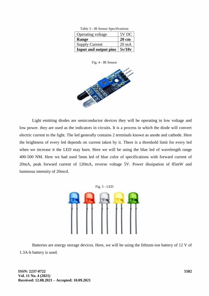
They work on the principle of light waves and the Infrared light reflected from the object to
sensor will also be used to measure the distance between the object and the sensor. So here range
plays a major role in detection of object. It has a transmitter in which it which it emits the Infrared
radiations they are also called as IR-LRDs and the next is IR receivers in which they will receive the
radiation from the IR transmitters.
ISSN: 2237-0722
Vol. 11 No. 4 (2021)
Received: 12.08.2021 – Accepted: 10.09.2021
5582
Table 3 - IR Sensor Specifications
Operating voltage 5V DC
Range 20 cm
Supply Current 20 mA
Input and output pins 5v/10v
Fig. 4 - IR Sensor
Light emitting diodes are semiconductor devices they will be operating in low voltage and
low power. they are used as the indicators in circuits. It is a process in which the diode will convert
electric current to the light. The led generally contains 2 terminals known as anode and cathode. Here
the brightness of every led depends on current taken by it. There is a threshold limit for every led
when we increase it the LED may burn. Here we will be using the blue led of wavelength range
400-500 NM. Here we had used 5mm led of blue color of specifications with forward current of
20mA, peak forward current of 120mA, reverse voltage 5V. Power dissipation of 85mW and
luminous intensity of 20mcd.
Fig. 5 - LED
Batteries are energy storage devices. Here, we will be using the lithium-ion battery of 12 V of
1.3A-h battery is used.

ISSN: 2237-0722
Vol. 11 No. 4 (2021)
Received: 12.08.2021 – Accepted: 10.09.2021
5583
Table 4 - Battery Specifications
Nominal voltage 12V
Rated cap 1.3AH
Operational temperature
During Charge 0°C (32°F) - 40°C (104°F)
During Discharge -20°C (-4°F) - 50°C (122°F)
During Storage -20°C (-4°F) - 40°C (104°F)
Capacity 25° (77°F)
At 20-hour rate (0.165A) 1.3AH
At 10-hour rate 1.17AH
At 5-hour rate 1.04AH
At 1 hour rate (1.98A) 0.78AH
Maximum discharge current 19.5A
Fig. 6 - Lithium Battery
It is a 2-terminal component that will be conducting current in only one direction it severely
opposes the current to flow in other direction. Today, diodes are only made of silicon. Most of the
diode uses p-n junction. Diodes can protect the circuits by limiting the voltage and it can also convert
AC to DC.
Table 5 - Diode Specifications
Diode(used) 1N4007
Diode Type Silicon Rectifier general usage diode
Max reverse voltage 1000V
Average forward current 1000mA
Maximum forward current 30A
Maximum storage and operating temperature -55 to +175 Centigrade
Maximum power dissipation 3W
Fig. 7 - Diode (IN4007)

ISSN: 2237-0722
Vol. 11 No. 4 (2021)
Received: 12.08.2021 – Accepted: 10.09.2021
5584
It will be converting ac voltage into dc voltage which will be given to the diode. Generally, a
full wave bridge rectifier will use 4 diodes and one resistive load. They have low power loss so that
no voltage signal is wasted in this process. Here we will be using W10 1000v, 1.5A silicon single
phase bridge rectifier of specifications.
Table 6 - Full Wave Bridge Rectifier
Peak reverse voltage 1000V
Maximum RMS voltage 700V
Maximum DC blocking voltage 1000V
Maximum forward voltage 1V
Peak forward current 1.5A
Maximum reverse current 10μ
Fig. 8 - Full Wave Bridge Rectifier
3. System Implementation
The basic principle is to convert the mechanical energy into electric energy, through the
piezoelectric transducer. The figure shows the block diagram of working of smart LED. The
piezoelectric transducers are placed on the road, The energy is harvested from these piezoelectric
transducers and stored in the battery using the rectifier circuit, This energy which is stored in a
battery by the piezoelectric process is used as the power supply for the circuit, The system starts to
works only at low or poor lighting conditions i.e. in evening and night time, Once the system starts

ISSN: 2237-0722
Vol. 11 No. 4 (2021)
Received: 12.08.2021 – Accepted: 10.09.2021
5585
working the light will be on and will be glow at low intensity, The IR Sensor will be monitored
continuously and once the vehicle movement is sensed the lights will start glow at the high intensity
and lights will glow in low intensity when there is no movement.
Fig. 9 - Flowchart of the System
The system starts working by making use of power supply which is store in the battery by the
piezoelectric process, the microcontroller will keep on monitoring the LDR once the resistance is
high the streets will turn on, If the resistance of LDR is low the microcontroller will continue
monitoring, once the lights are on the microcontroller will monitor IR sensor output when the
vehicles are detected by the IR sensor the lights will start glowing in high intensity, when no vehicles
are detected the lights will glow with low intensity, as soon as the LDR resistance is low the system
stops working and microcontroller will continue to monitor LDR.

ISSN: 2237-0722
Vol. 11 No. 4 (2021)
Received: 12.08.2021 – Accepted: 10.09.2021
5586
Fig. 10 - Flowchart for LDR
Firstly, Connections are made as of the circuit diagram. Code plays a major role in the
working of the equipment. Present days Smart Street Light system is a major component of smart city
infrastructure.
The main function of this system is to lighten the city streets using Sensors so that we can
save power energy. In the existing system using normal lamps consumes more amount of energy and
also it is very expensive. In order to minimize the consuming of power and cost we must use LED’s.
Using IOT systems is all around the world. It is mandatory to watch all kinds of places in the cities.

ISSN: 2237-0722
Vol. 11 No. 4 (2021)
Received: 12.08.2021 – Accepted: 10.09.2021
5587
Fig. 11 - Connection diagram of Arduino UNO
The Working Procedure of Smart Street Light using IR sensors is described as follows. It
consists of following steps. The output pin of LDR is connected to Analog port of Arduino Uno
board. Connecting all the output pins of IR sensors to the input port of Arduino Board respectively.
Connecting all the ground of IR sensors to the GND port. The output of all the LEDs is connected to
port 2, 3, 4, 5, 6 respectively. Connecting all the negative terminals of LEDs to the GND port.
Fig. 12 - Circuit Diagram of Piezoelectric Transducer
4. Result
As a result of this project, we are using piezoelectric transducers, IR, LDR sensors and LEDs.
The Use of IR sensor is to detect the vehicles which pass on the road and then the light will glow with
high intensity. Intensity of the lights get reduced when the vehicle passes away from the sensor
ISSN: 2237-0722
Vol. 11 No. 4 (2021)
Received: 12.08.2021 – Accepted: 10.09.2021
5588
detection.it can save the power. Using a piezoelectric transducer which will be able to convert the
pressure (given by the vehicles in roads) to electrical energy which is stored in the battery.
LDR sensor will operate the light automatically and reduces the manpower. It will help to stop
the lights during daytimes. The main result is that calculating the battery power and battery life of the
li -ion battery.
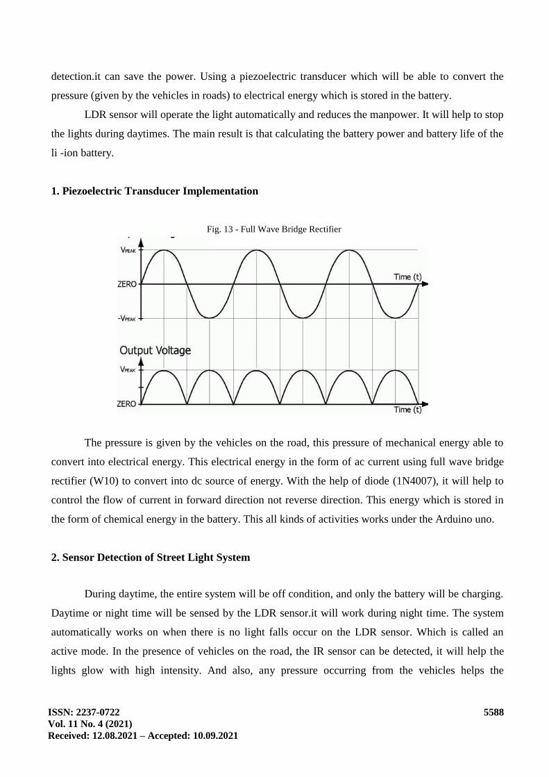
1. Piezoelectric Transducer Implementation
Fig. 13 - Full Wave Bridge Rectifier
The pressure is given by the vehicles on the road, this pressure of mechanical energy able to
convert into electrical energy. This electrical energy in the form of ac current using full wave bridge
rectifier (W10) to convert into dc source of energy. With the help of diode (1N4007), it will help to
control the flow of current in forward direction not reverse direction. This energy which is stored in
the form of chemical energy in the battery. This all kinds of activities works under the Arduino uno.
2. Sensor Detection of Street Light System
During daytime, the entire system will be off condition, and only the battery will be charging.
Daytime or night time will be sensed by the LDR sensor.it will work during night time. The system
automatically works on when there is no light falls occur on the LDR sensor. Which is called an
active mode. In the presence of vehicles on the road, the IR sensor can be detected, it will help the
lights glow with high intensity. And also, any pressure occurring from the vehicles helps the
ISSN: 2237-0722
Vol. 11 No. 4 (2021)
Received: 12.08.2021 – Accepted: 10.09.2021
5589
transducer to convert it and store it in the battery. Overall result is that the hardware implementation
of smart led street lights under works on Arduino uno.
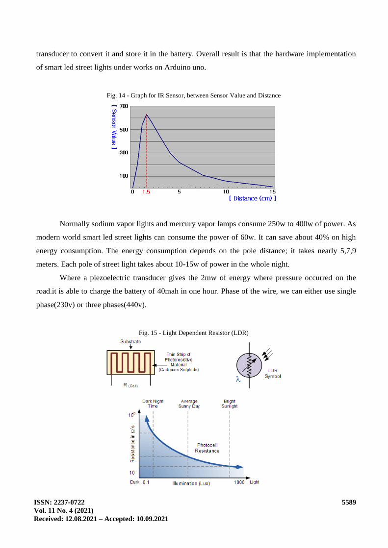
Fig. 14 - Graph for IR Sensor, between Sensor Value and Distance
Normally sodium vapor lights and mercury vapor lamps consume 250w to 400w of power. As
modern world smart led street lights can consume the power of 60w. It can save about 40% on high
energy consumption. The energy consumption depends on the pole distance; it takes nearly 5,7,9
meters. Each pole of street light takes about 10-15w of power in the whole night.
Where a piezoelectric transducer gives the 2mw of energy where pressure occurred on the
road.it is able to charge the battery of 40mah in one hour. Phase of the wire, we can either use single
phase(230v) or three phases(440v).
Fig. 15 - Light Dependent Resistor (LDR)

ISSN: 2237-0722
Vol. 11 No. 4 (2021)
Received: 12.08.2021 – Accepted: 10.09.2021
5590
The intensity of light depends on the luminous power. Which is luminous flux per area
illuminated by the light, measured in lux. 1lux=0.092fc (lumen/mq). That is equal to one square
meter. This means that the light will be brighter closer to the light source. Otherwise, it’s far away
from the light source.
Calculate the intensity of light Where i = light intensity (cd), K = luminous efficacy
φ = Flux(lm). The K average luminous efficacy of 1 watt lamp types HPLN is 42 lm/watt with power
(P) is 1 watt and the angle is ω = 4π space is
Consider 12 hours of a day during night time, a bulb can consume the energy of 150w/number
of nodes is nearly 15.and calculate the power consumed per day=15*12*150/1000 = 27units that is
27*30=810 units per month.
Calculate the battery power and battery life of the li ion battery.in our project, Average
current=8mA, operating voltage=5v, average power stored by the battery=V*A=12*5=60mW.
Battery life: battery capacity=1.3mAh, battery voltage=12v, power=12*1.3=156mWh,
Battery life=156/60=2.6 hrs.
3. Code Snippet
int led = 3;
int led1 = 10;
int led2 = 5;
int led3 = 9;
int ldr = A0;
void setup(){
Serial.begin (9600);
pinMode (led,OUTPUT);
pinMode (led1,OUTPUT);
pinMode (led2,OUTPUT);
pinMode (led3,OUTPUT);
pinMode (ldr,INPUT); }
void loop()
{int ldrStatus = analogRead (ldr); //ldr
if (ldrStatus <=14){
if (analogRead(A1)<500){ // IR 1 CODE

ISSN: 2237-0722
Vol. 11 No. 4 (2021)
Received: 12.08.2021 – Accepted: 10.09.2021
5591
digitalWrite(led,HIGH);
digitalWrite(led1,HIGH);
delay(1000);}
else {digitalWrite(led,HIGH);
analogWrite(led,255/5);
delay(50); }
if (analogRead(A2)<500) { // IR 2 CODE
digitalWrite(led1,HIGH);
digitalWrite(led2,HIGH);
delay(1000);}
else{
digitalWrite(led1,HIGH);
analogWrite(led1,255/5);
delay(50);}
if (analogRead(A3)<500){ // IR 3 CODE
digitalWrite(led2,HIGH);
digitalWrite(led3,HIGH);
delay(1000);}
else {
digitalWrite(led2,HIGH);
analogWrite(led2,255/5);
delay(50);}
if (analogRead(A4)<500){ // IR 4 CODE
digitalWrite(led3,HIGH);
delay(1000);}
else{
digitalWrite(led3,HIGH);
analogWrite(led3,255/5);
delay(50);} }
else{
digitalWrite(led, LOW);
digitalWrite(led1, LOW);

ISSN: 2237-0722
Vol. 11 No. 4 (2021)
Received: 12.08.2021 – Accepted: 10.09.2021
5592
digitalWrite(led2, LOW);
digitalWrite(led3, LOW);}}
4. Hardware Implementation
Fig. 16 - Output during Daytime
The pressure which is applied in the road by the vehicles which has piezoelectric transducer is
converted to electrical energy by piezoelectric transducer. To maintain it in DC current, a full wave
bridge rectifier is used and a diode is attached to neglect backward current.
Fig. 17 - Output during Night Time
This current is stored in the lithium-ion battery which can be used for the power supply of
Arduino UNO. Thus, it will control the LEDs, IR sensor and LDR. When vehicle passes the street
light, the LED will glow bright which is sensed by the IR sensor and will remain dim when there is
ISSN: 2237-0722
Vol. 11 No. 4 (2021)
Received: 12.08.2021 – Accepted: 10.09.2021
5593
no vehicle. Also, during daytime, the LEDs will be in OFF condition and during night time, it will be
in ON condition which is detected by LDR.
5. Conclusion
This paper presents adaptive research for Smart LED Street lights. LEDs play a major role for
lighting options in future facilities, due to its low power consumption and very cost effective. Our
main objective is to use the piezoelectric transducer it helps to run the smart led street lights. It will
help to eliminating the conventional power source and sodium vapor street lights. We can use sensors
to monitor the vehicles in the road. The use of transducer it able to convert pressure (mechanical
energy) into electrical energy, this energy which is used in our street lights. During daytime, charging
takes place which is stored in the battery. This charged energy using during night time it depends on
vehicles cross on the road. Otherwise, the light will be dim.
In conclusion, we conclude that the conventional lights consume the most energy from
thermal power stations and other energy resources.in case of that we were using smart led street lights
it takes nearly 60% more energy than conventional. It helps to save energy. Furthermore, we
conclude that the intensity of light will be controlled according to the environmental need using
sensors to detect the vehicles which are all controlled by Arduino Uno. With the few limitations such
as low amount of power generated using the power harvesters, the researchers are working towards
generating new methods.
References
Geffrey K. Ottman, Heath F. Hofmann, Archin C. Bhatt and George A. Lesieutre, “Adaptive
Piezoelectric Energy Harvesting Circuit for Wireless Remote Power Supply”, IEEE Transactions on
Power Electronics, vol. 17 no.5, pp. 669-676, 2002.
A review of energy harvesting using piezoelectric materials: state-of-the-art a decade later
(2008–2010). Mohsen Safaei, Henry A Sodano and Steven R Anton Published 22 October 2019 • ©
2019 IOP Publishing Ltd Smart Materials and Structures, Volume 28, Number 11Citation Mohsen
Safaei et al 2019 Smart Mater. Struct. 28 113001.
A Khalig, P. Zeng, C Zheng. "Kinetic Energy Harvesting Using Piezoelectric and Electromagnetic
Technologies-State of the Art. Industrial Electronics, IEEE Transactions on., vol. 57, no.3,
pp. 850-860. March 2010.
H.A. Sodano H.A. and D.J. Inman, "Comparison of piezoelectric Energy harvesting devices for
recharging Batteries", LA-UR-04-5720, Journal of Intelligent Material Systems and Structures,
16(10), 799-807, 2005.

ISSN: 2237-0722
Vol. 11 No. 4 (2021)
Received: 12.08.2021 – Accepted: 10.09.2021
5594
P. Glynne-Jones, S.P. Beeby, and N.M. White, “Towards a piezoelectric vibration-powered micro
generator,” IEE Proc. Sci. Meas. Technol., vol. 148, no. 2, pp. 68–72, 2001.
T.G. Engel, “Energy conversion and high-power pulse production using miniature piezoelectric
compressors,” IEEE Trans. Plasma Sci., vol. 28, no. 5, pp. 1338–1340, Oct. 2000.
Platt, S.R., Farritor, S., Garvin, K., &Haider, H, “The use of piezoelectric ceramics for electric power
generation within orthopedic implants.” IEEE/ASME Transactions on Mechatronics, 10(4), 455–461,
2005.
Reza Mohamaddoust , Abolfazl Toroghi Haghighat, Mohamad Javad Motahari Sharif and Niccolo
Capanni, “A Novel Design of an Automatic Lighting Control System for a Wireless Transducer
Network with Increased Transducer Lifetime and Reduced Transducer Numbers”, Transducers
(2011) ,Volume No.- 11(9), pp. 8933-8952.
Jing Chunguo, Wang Yan Sun, Wenyi Song, “Design of Street Light Pole Controller Based on
WSN”, The Tenth International Conference on Electronic Measurement & Instruments, ICEMI,
(2011), 147 – 150.
Shentu, Xudan; Li, Wenjun; Sun, Lingling; Gong, Siliang, “A new streetlight monitoring system
based on wireless transducer networks”, International Conference on Information Science and
Engineering, pp. 6394 – 6397.
Wu Yue; Shi Changhong; Zhang Xianghong; Yang Wei; “Design of new intelligent street light
control system”, 8th IEEE international Conferences on Control and Automation (ICCA), (2010),
Page(s): 1423 – 1427.
Hengyu Wu; Minli Tang; Guo Huang, “Design of multifunctional street light control system based on
AT89S52 single-chip microcomputer”, IEEE 2nd International Conferences on Industrial
Mechatronics and Automation (ICIMA), (2010), Page(s): 134 – 137.
P.C. Joshin, M. Joseph, S. James and V. Sasidhara, “Automation using power line communication
with web-based access,” Int. J. Adv. Res. Electr. Electron. Instrum. Eng., 4(1), pp. 229-234, 2015.
K.H.S.D. Abhishek and K. Srikant, “Design of smart street lighting system,” Int. J. Adv. Eng., vol. 1,
pp. 23-27, 2015.
K.S. Sheela and S. Padmadevi, “Survey on street lighting system based on vehicle movements,” Int.
J. Innovative Res. Sci. Eng. Technol., vol. 3, no. 2, pp. 9220-9225, 2014.
R. Banerjee, “Solar tracking system,” Int. J. Sci. Res. Publ., vol. 5, no. 3, pp. 1-7, 2015.
M. Srikanth and K.N. Sudhakar, “Zigbee based remote control automatic street light system,” Int. J.
Eng. Sci. Comput., pp. 639-643, 2014.
A. Chammam, W. Nsibi and M. Nejib Nehdi, “Behaviour of a high-intensity discharge lamp fed by a
high-frequency dimmable electronic ballast,” Sage J., vol. 49, no. 2, pp. 277-284, 2017.
A. Iorkyaa, A.I. Richard and A.N. Amah, “The efficacy of light emitting diode (led) lamps used in
rural communities of Nigeria,” Energy Environ. Res., vol. 2, no. 1, pp. 121-127, 2012.
Sindhu.A.M, Jerin George, Sumit Roy, Chandra J, “Smart Streetlight Using IR Sensors”, 2394-0050,
P-ISSN: 2394-0042.Volume 3, Issue 2. (Mar. - Apr. 2016), PP 39-44.