int imp platform switched
TRANSCRIPT

8/3/2019 Int Imp Platform Switched
http://slidepdf.com/reader/full/int-imp-platform-switched 1/11
s
141
The Effect of Interimplant Distance on
the Height of the Interimplant Bone
Crest When Using Platform-Switched
Implants
Xavier Rodrfguez-Ciurana, MO, PhO*
Xavier Vela-Nebot, MO, 005*
Maribel Segala- Torres, MO, 005*
Jose Luis Calvo-Guirado, ~OS, MS, PhO** .
Jordi Cambra, MO, 005*
Vfctor M~ndez-Blanco, 005***
Dennis P . Tarnow, 005****
A distance of more than 3 mm between two adjacent standard implants has been
shown to preserve the interproximal bone peak, resulting in only 0.45 mm of
resorption. Thepurpose of this study was to determine whether use of the plat-
form-switching technique wou7d change the bone resorption patterns between
adjacent implants placed less than 3mm apart Radiographic studies of bone
resorption around 41 pairs of implants placed less than 3 mm apart in 37 patients
were carried out Mean vertical bone resorption was 0.62 mm, and the mean hori-
zontal component was 0.60 mm. The bone peak that extended coronally beyond
an imaginary line connecting the two implant-abutment interfaces was measured,
and the mean bone height preservation above this interimplant line was 0.24 mm.
(Int J Periodontics Restorative Dent 2009;29: 141-151.)
*Private Practice, Barcelona, Spain.
**Senior Lecturer of General and Implant Dentist ry, University of Murcia, Spain.
***Private Pract ice, Madrid, Spain.
****Professor of Periodontology and Implant Dentistry, New York University College of
Dentistry, New York, New York, USA
Correspondence to: Dr Xavier Rodrfguez-Ciurana, C/ Ganduxer 122 08022, Barcelona
BCN Spain; fax: +34-934181668; email: [email protected].
Multiple researchgroups haveestab-
lished that a biologic width exists
around all dental implants.":" This istrue for all implants of all shapes,
whether on one-stage implantsor after
uncovering in two-stage placement
protocols on two-piece irnplants.l-v'
Peri-implant bone loss around
implants exposed to the oral environ-
ment also has been documented
extensively.':"Suchresorptionappears
to be related primarily to exposure of
the implant to the oralenvironment.v"
It hasbeen demonstrated thatthe gapbetween the implant and the abut-
ment hasa direct effect on bone loss,
reqardless of whether the two parts
are connected at the time of implant
placement or after initial submergence
~nd integration of the implant.' This
phenomenon occurs whether the
implant is loaded or unloaded and
appearsto beunrelated to the implant
surfacetreatment.v? Management of
such bone resorption isan important
factor in achieving good esthetic
results in the anterior maxilla and in
optimizing bone support.10,11
Vertical bone resorption, which
often extends 1 to 2 mm below the
implant-abutment interface,diminishes
Volume 29, Number 2,2009

8/3/2019 Int Imp Platform Switched
http://slidepdf.com/reader/full/int-imp-platform-switched 2/11
142
the bone-to-implant contact surface
and thus, impairsthe biomechanics of
restorations.3,4 Horizontal bone loss
leadsto resorption of the buccalplate
innarrowalveolarcrests,aswell asloss
of the interproximal bone peak andlossof support for the adjacent inter-
implant papilla.
When two implants are placed
adjacent to one another, the distance
between them has been demon-
strated to affect the extent of lateral
bone lossand interproximalbone peak
resorption. A distance of more than 3
mm between two adjacent implants
appearsto preservethe interproximal
bone peakand result inonly 0.45mmof resorptionon averaqe.l-' Incontrast,
if the space between the implants is
3mmor less,averageresorptionof the
interproximal bone peak increasesto
1.04mm,which compromisessupport
for the interimplant papilla.F
Fig 1 Platform-switching design using the
example of a 4.8-mm implant with a 4.1-
mm abutment.
To reduce the effects of peri-
implant bone resorption, a technique
known as platform switching was
recently developed.13-15 The concept
behind platform switching is that by
shifting ,the implant-abutment inter-facemedially,the deleterious impact of
the implant-abutment microgap on
the peri-implant bone canbe reduced.
Platform switching thus involves the
use of abutments with a diameter
smaller than that of the implant plat-
forrn.!" This geometry shifts the
perimeter of the implant-abutment
junction inwardtoward the central axis
of the implant.!" Commonly, for
instance, an implant with a 4.8-mm-diameter platform is connected to a
4.1-mm-diameter abutment, creating
a distance .of 0.35 mm between the
implant-abutment interface and the
peri-implant tissues(Fig 1).
Platform switching has been
shown to result in an average of 0.76
mm of vertical bone resorption, a
reduction of 70%versusconventional
restoration with a matching abut-
rncnt." While a reduction in horizon-tal bone resorption also has been
observed in radiographs of platform-
switched implants, the impact of plat-
form switchingonhorizontal bone loss
hasnot previously been directly stud-
ied and documented.
Thus, the purpose of this study
was to determine whether platform-
switchedadjacent implantsplaced less
than 3mmapartexhibited lessvertical
and/or horizontalbone resorptionthanhas been previously documented
around non-platform-switched
implants.
The International Journal of Periodontics & Restorative Dentistry

8/3/2019 Int Imp Platform Switched
http://slidepdf.com/reader/full/int-imp-platform-switched 3/11
143
Fig 2 Measurements obtained around the examined implants.
Fig~2a (left) (nterimplant distance = the
distance between two adjacent implants.
Method and materials
Patientsfrom three private clinicswere
recruitedto participate inthis prospec-
tive study. All participants were
required to be 18 yearsor older and
provide informed consent to undergo
radiography of their implants.
A total of 82 adjacent implants
(41 pairs) placed in 37 patients were
measured(20women and 17men).Of
the 41 pairs of implants, 27 were
placed in the maxilla and 14 in the
mandible. Elevenwere placed in the
anterior zone(incisorsto canines),and
30 were placed in the posterior arch
(premolars and molars). All the
implants were two-piece rough-
surfaced platform-switched designs.
Fig 2b (right) Horizontal bone resorption.
b1 (mesial) =distance from the interimplant
bone peak to the mesial implant; b2 (distal)=distance from the interimplant bone peak
to the distal implant.
Fig 2c (left) Vertical bone resorption. c1(mesial) =mesial distance from the implant-
abutment interface to the most coronal
point of contact between the interproximal
face of the implant and the bone; c2 (distal)
=distal distance from the implant-abutment
interface to the most coronal point of con-tact between the interproximal face of the
implant and the bone.
Fig 2d (right) Bone peak retention. Distance
from the 'bone peak to the imaginary line
connecting the two implant-abutment
interfaces; this is expressed as a positive
(d+) or negative (d-) number in millimeters.
All implants were placed at the lower
bone level of the peri-implant bone
tissue sothat the whole implant plat-
form wascoveredby bone. Thisplace-
ment sometimes meant that the
implant was located at the crest on
one sideand subcrestallyon the other.
All implants had been restoredfor 6 to
,24 month's before being measured
radiographically. This means that the
prosthetic abutment had been dis-
connected and reconnected at least
four times before radiographic mea-
surementswere made.
Thirty pairs had an implant plat-
form diameter of 4.8 mm and anabut-
ment platform of 4.1 mm (Prevail
4/5/4, Biometl3i). Inthese30patients,
the discrepancy between the implant
and abutment platformswas0.35mm.
Three patients had implants with a
diameter of 6.0 mm and abutments
with a 5.0-mm platform (Prevail5/6/5,
Biometl3i). In these 3 cases,the dis-
crepancy between the implant and
abutment platforms was 0.5 mm.
Sevenpatientshad implantsof 5.0mm
diameter and abutments with a 4.1-
mmplatform (XP4/5/4, Biornet/Si),for
adiscrepancyof 0.45mm.One patient
had implants of 4.1 mm diameter and
abutments with a 3.4-mm platform
(Prevail4/3, Biometl3i), for a discrep-
ancy of 0.35 mm. The discrepancies
between the implant and abutment
platforms thus ranged from 0.35 to
0.50 mm.
Volume 29, Number 2,2009

8/3/2019 Int Imp Platform Switched
http://slidepdf.com/reader/full/int-imp-platform-switched 4/11
144
Results of implant and bone measurements
a=the distance between the two implants in mi ll imeters; b, and b2=distance (b., mesial; b
2, dis-
tal) from the interimplant bone peak to the implant; c, and c2 =vertical bone resorption (c,mesial; c2, distal) determined by measuring from the implant-abutment interface to the mostcoronal point of contact between the interproximal face of the implant and the bone; d= i f thebone peak extended coronally beyond the imaginary l ine connecting the two implant-abutmentinterfaces, it was expressed asa posit ive number in mil limeters. Ifthe bone peak did not reachthe imaginary l ine connecting the two implant-abutment interfaces, it was expressed asa nega-tive number in millimeters.
Periapical radiographs were
obtained with the Kodak RVG 6000
Digital Radiography System (Eastman
Kodak) in high-resolution mode. The
use of periapical radiographs with the
parallel technique in reproducible pro-
jections isa routine diagnostic imagi~g
procedure to evaluate peri-implant
bone."? A mouthpiece was employed
to ensure a parallel technique and
reproducibility between preoperative
and postoperative radiographs. Bone
loss was measured using previously
calibrated Kodak Trophy software.
The following measurements were
then made and recorded (Fig 2):
1. The distance between the two
implants was determined by mea-
suring between the two implants at
the implant shoulder.
2. Horizontal bone resorption was
determined by measuring the dis-
tance from the interimplant bone
peak to the implant (b., mesial; b2,
distal).
3. Vertical bone resorption was deter-
mined by measuring from the
implant-abutment interface to the
most coronal point of contact
between the interproximal face of
the implant and the bone (c.,mesial;
c2, distal).
4. Ifthe bone peak extended coronally
beyond an imaginary line connect-
ing the two implant-abutment inter-
faces, it was expressed asa positive
number in millimeters. If the bone
peak did not reach the imaginary
line connecting the two implant-
abutment interfaces, it was
expressed asa negative number in
millimeters.
Statistical analysis (means, stan-
dard deviations [SDs],frequencies) was
performed with the SPSS12 program
(SPSSInc).
The International Journal of Periodontics & Restorative Dentistry

8/3/2019 Int Imp Platform Switched
http://slidepdf.com/reader/full/int-imp-platform-switched 5/11
145
Results
Measurements between the implant-
abutment junctions of each pair con-
firmed that each pair had been placed
less than 3 mm apart. The mean dis-
tance between implants (a) was
2.23 mm, with an SD of 0.55 mm.
The mean distance from the
mesial implant shoulder to the inter-
implant bone peak (b.) was 0.60 mm,
with an SD of 0.38 mm. The mean dis-
tance from the distal implant shoulder
to the interimplant bone peak (b2) was
0.59 mm, with an SD of 0.46 mm.
The mean distance from the
implant-abutment interface to the
most coronal point of contact between
the face of the mesial implant and the
bone (c.) was 0.70 mm, with an SD of
0.57 mm. The mean distance from the
implant-abutment interface to the
most coronal point of contact between
the face of the distal implant and the
bone (c2) was 0.55 mm, with an SD of
0.52 mm.
The mean distance from the inter-implant bone peak to the imaginary
line connecting the two implant-
abutment interfaces(d)was+0.24 mm,
with an SDof 0.85 mm. In26 ofthe 41
pairs (64%), the peri-implant crestal
bone peak was preserved, while it
was lost in 15 of the 41 cases (36%).
Table 1 summarizes these findings.
Discussion
The results of this study document
less bone resorption in both the ver-
tical and horizontal directions follow-
ing oral exposure of platform-
switched implants, as compared to
non-platform-switched implants (Fig
3). These findings suggest that the
biologic width around platform-
switched implants is located more
coronally than the biologic widt~
around non-platform-switched
implants; these findings are in agree-
ment with the study of Becker et al.18
Some investigators have reported
less bone resorption in platform-
switched implants than in other
non-platform-switched irnplants.l'' 19,20
Infact, the Ankylos implant has shown
vertical bone resorption of less than
0.5 mm up to 2.0 mm after oral expo,:
sure.'?Astra Tech implants have shown
amean vertical bone resorption of 0.09
mm. The absence of radiologic studies
regarding horizontal bone resorption
with platform-switched implant
designs must be noted.2 o
Typically, vertical bone resorption
aroundnon-platform-switched implants
is about 2 mm,3,4whereas the mean
vertical resorption was 0.62 mrn in this
study series,again of 69%. Inan earlier
study,15 the mean vertical bone resorp-tion component around implantswith a
5.0-mm implant collar and a 4.1-mm
abutment platform was 0.76 mm.
Unintentional or repeated inten-
tional disconnection ofthe abutments
on two-piece implants hasbeen shown
to disrupt soft tissue integration. This
induces increased marginal bone
remodeling and buccal recession and
has important clinical irnplications."
The handling protocol of our studyincluded at least 4 abutment manipu-
lations before seating of the definitive
prosthesis. This means that the
observed bone resorption would be
that typically seen with the standard
loading protocol.
Volume 29, Number 2,2009

8/3/2019 Int Imp Platform Switched
http://slidepdf.com/reader/full/int-imp-platform-switched 6/11
146
Fig 3 Radiographs of seven patients in whom two adjacent implants were placed less than 3 mm apart in dif ferent locat ions.
Fig 3a Patient 1. Implants placed in the
maxilla (central incisors). (left) Before load-
ing. (right) After 12 months of loading.
Fig 3b Patient 2. Implants placed in the
maxilla (left premolar area). (left) Before
loading. (right) After 12 months of loading.
Fig 3c Patient 3. Implants placed in the
maxilla (central incisors). (left) Before load-
ing. (right) After 12 months of loading.
The Internat ional Journal of Periodont ics & Restorat ive Dent istry
8/3/2019 Int Imp Platform Switched
http://slidepdf.com/reader/full/int-imp-platform-switched 7/11
147
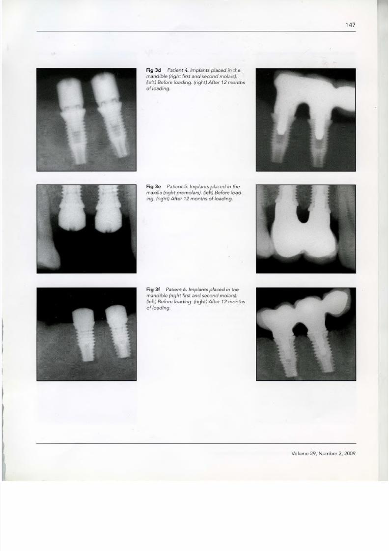
Fig 3d Patient 4. Implants placed in the
mandible (right first and second molars).
(left) Before loading. (right) After 12 months
of loading.
Fig 3e Patient 5. Implants placed in the
maxilla (right premolars). ~eft) Before load-
ing. (right) After 12 months of loading.
Fig 3f Patient 6. Implants placed in the
mandible (right firs t and second molars).
(left) Before loading. (right) After 12 months
of loading.
Volume 29, Number 2,2009

8/3/2019 Int Imp Platform Switched
http://slidepdf.com/reader/full/int-imp-platform-switched 8/11
148
Fig 3g Patient 7. Implants placed in the
mandible (left first and second molars). (left)
Before loading. (right) After 12 months of
loading.
Fig 4 Radiographs of two patients with adjacent implants placed less than 2 mm apart. Note the preservation of the interimplant bone peak.
Fig 4a Patient 8. Implants placed in the
maxillary right premolar area. (left) Before
loading. (right) After 12 months of loading.
Fig 4b Patient 9. Implants placed in the
maxillary central incisor positions. (left )
Before loading. (right) After 12 months of
loading.
The International Journal of Periodont ics & Restorative Dentistry

8/3/2019 Int Imp Platform Switched
http://slidepdf.com/reader/full/int-imp-platform-switched 9/11
149
Fig S Esthetic results after prosthetic restoration.
Fig Sa Patient 8. Screw-retained porcelain-
fused-to-metal prosthesis. Implants were
placed in the maxillary right premolar
positions, as seen in Fig 4a.
Fig Sb Patient 9. Screw-retained porcelain-
fused-to-metal prosthesis for the four
incisors, with the lateral incisors as can-
tilevers. Implants were placed inthe central
incisorpositions, as seen in Fig 4b.
The mean horizontal bone resorp-
tion inthe present study was 0.60 mm,
a 57% improvement over that seen in
an earlier study of non-platform-switched implants of (1.4 mm).12With
a platform-switching design, the bone
resorption is significantly less. This
bone preservation may also provide
better support for the soft tissues.
It must be noted that in seven
cases, the implants were placed less
than 2 mm apart, and the distance
from the crestal bone peak to the
imaginary line connecting the two
implant-abutment interfaces was pos-itive (Fig 4).The esthetic and functional
advantages of a more coronal biologic
width location are obvious. Inedentu-
lous sectors when the implants must
be placed less than 3 mm apart
(between 1.5 and 3 rnrn), it is possible
to retain a bone peak. This aids in the
formation of the interimplant papilla.
By reducing the vertical and horizontal
components of bone loss,the buccalbone margin is preserved, protecting
the implant and improving esthetic
results (Fig 5).
The use of an immediately loaded
abutment that issmallerthan the diam-
eter of the implant body can help to
protect the peri-implant mineralized
tissues.F Thisfact could be very impor-
tant in the rehabilitation of atrophic
arches.
Volume 29, Number 2,2009

8/3/2019 Int Imp Platform Switched
http://slidepdf.com/reader/full/int-imp-platform-switched 10/11
150
Conclusions
The platform-switching technique can
help to preserve peri-implant bone
and retain the interproximal bone peak
better than conventional implant
restorations. This bone preservation
leads to better support for the soft
tissues and improves the crown-to-
implant ratio. In narrow edentulous
sectors where implants must be placed
lessthan 3 mm apart (between 1.5 and
3 mrn), it is possible to retain a bone
peak with platform-switched implants.
Because this implant design results in
more coronal bone-to-implant con-
tact, it may be more suitable for the use
of short implants and in atrophic areas.
References
1. Berglundh T, Lindhe J. Dimension of the
peri-implant mucosa. Biological width
revisited. J Clin Periodontol 1996;23.:
971-973.
2. HanssonHA, Albrektsson T,Branernark PI.
Structural aspects ofthe interface between
tissue and titanium implants. J Prosthet
Dent 1983;50:108-113.
3. Hermann JS,Cochran DL, Nummikoski pv,
Buser D. Crestal bone changes around
titanium implants. A radiographic evalua-
tion of unloaded nonsubmerged and sub-
merged implants in the canine mandible.
J PeriodontoI1997;68:1117-1130.
4. Hermann JS, Buser D, Schenk RK,
Schoolfield JD, Cochran DL. Biologic width
around one- and two-piece titanium
implants. Clin Oral Implants Res
2001;12:559-571.
5. King GN, Hermann JS, Schoolfield JD,
Buser D, Cochran DL. Influence ofthe size
of the microgap on crestal bone levels in
non-submerged dental implants: A radi-
ographic study in the canine mandible. J
Periodontol 2002;10:1111-1117.
6. Kingle B, Meyle J. Soft-tissue integration
of implants. Consensus report of Working
Group 2. Clin Oral Implants Res2006; 17
(suppl 2}:93-96.
7. Kawahara H, Kawahara D, Mimura Y,
TakashimaY,Ong JL. Morphologic studies
on the biologic seal of titanium dental
implants. Report II. In vivo study on the
defending mechanism of epithelial adhe-
sions/attachment against invasive factors.
Int J Oral Maxillofac Implants 1998;13:
465-473.
8. Callan DP, Cobb CM, Williams KB. DNA
probe identification of bacteria colonizing
internal surfaces of the implant-abutment
interface: A preliminary study. J
PeriodontoI2005;76:115-120.
9. Cochran DL, Hermann JS, Schenk RK,
Higgenbottom FL,BuserD. Biologic widtharound titanum implants. A histometric
analysis of the implanto-gingival junction
around unloaded and loaded nonsub-
merged implants in the canine mandible.
J PeriodontoI1997;68:186-198.
10. Buser D, Martin W, Belser Uc. Optimizing
esthetics for implant restorations in the
anterior maxilla: Anatomic and surgical
considerations. Int J Oral Maxillofac
Implants 2004; 19(suppl}:43-61.
11. Tarnow D, ElianN, Fletcher P,et al. Vertical
distance from the crest of bone to height
ofthe interproximal papilla between adja-cent implants. J Periodontol 2003;74:
1785-1788.
12. Tarnow DP,Cho SC,Wallace SS.The effect
of inter-implant distance on the height of
inter-implant bone crest. J Periodontol
2000;71 :546-549.
13. CalvoGuirado JL, SaezYuguero MR, Pardo
Zamora G, Munoz Barrio E. Immediate
provisionalization on a new implant design
for esthetic restoration and preserving cre-
stal bone. Implant Dent 2007;16:155-164.
14. LazzaraRJ,Porter SS. Platform switching:
A new concept in implant dentistry for
controlling postrestorative crestal bone
levels. Int J Periodontics Restorative Dent
2006;26:9-17.
The International Journal of Periodontics & Restorative Dentistry

8/3/2019 Int Imp Platform Switched
http://slidepdf.com/reader/full/int-imp-platform-switched 11/11
151
15. Vela-Nebot X, Rodriguez-Ciurana X,
Rodado-Alonso C, Seqala-Torre s M.
Benefits of an implant platform modifica-
tion technique to reduce crestal bone
resorption. Implant Dent 2006; 15:
313-320.
16. Baumgarten H, Cocchetto R, Testori T,
Meltzer A, Porter S.A new implant design
for crestal bone preservation: Initial obser-
vations and case report. Pract Proced
Aesthet Dent 2005;17:735-740.
17. Becker W, Becker BE, Israelson H, et al.
One-step surgical placement of Brane-
mark implants: A prospective multicenter
clinical study. IntJ Oral Maxillofac Implants
1997;12:454-462.
18. Becker J, Ferrari D, Herten M, Kirsch A,
Schwartz F.Influence of platform switching
on crestal bone changes at non-sub-
merged titanium' implants: A histomor-
phometrital study in dogs. J Clin Perio-
dontol 2007;34:1089-1 096
19. Chou CT, Morris HF, Ochi S, Walker L,
DesRosiersD.AICRG, Part II : Crestal boneloss associated with the Ankylos implant:
Loading to 36 months. J Oral Implantol
2004;30: 134-143.
20. Arvidson K, Bystedt H, Frykholm A, von
Konow L, Lothigius E. Five-year prospec-
tive follow-up report of the Astra Tech
Dental Implant System inthe treatment of
edentulous mandibles. Clin Oral Implants
Res1998:9:225-234.
21. Rompen E, Domken 0, Degidi M, Pontes
AE, Piattelli A. The effect of material char-
acteristics, of surface topography and of
implant components and connections on
soft tissue integration: A literature review.
Clin Oral Implants Res 2006;17
(suppI2):55-67.
22. Degidi M, Iezzi G, Scarano A, Piattelli A.
Immediately loaded titanium implant with
a tissue-stabilizing/maintaining design
("beyond platform switch") retrieved from
man after 4 weeks: A histological and his-
tomorphometrical evaluation. A case
report. Clin Oral Implants Res 2008;19:
276-282.
&
Volume 29, Number 2,2009