instruction manual -...
TRANSCRIPT

Instruction manual►1800W Electric Beveler model B15►1100W Electric Beveler model B16
AC Induction Motor Mode
For your personal safety,READ and UNDERSTAND before using.
SAVE THESE INSTRUCTIONS FORFUTURE REFERENCE.
2
C. Borges Blanques nº 38 - P.I. La Borda
08140 Caldes de Montbui (Barcelona)
Tel.: 0034 93 865 35 68
E-mail: [email protected]
MAQUINARIA NOGVAL S.L.

1800W Electric Beveler Mode Power input 1800 W Vlotage See machine nameplate No Load r.p.m. 2300-6500 Speed Wheel Settings 1/ 2/ 3/ 4/ 5/ 6: 2300/ 2600/ 3700/ 4800/ 5800/ 6500 Std. Bevel Angle 45 Deg. Max. Chamfer Height 45 Deg. : 10.6 mm Mini. Dia. For Inside Bevels 30 mm Net Weight 6.5kgs ( 14.3Lbs)
Variable speed wheel Auxiliary handle
Bevel height scale
Adjustable dial ring
Support deck Indexable
Main handle
On/off trigger switch with lock pin
Tool holder
Impeller carbide insert
Warning: Tools equipped with over load protection, when motor has been cut off due to over load, always switch on machine with no load for at least 20 seconds to reduce temperature before switch on again to avoid burn out to the motor.
3

1100W Electric Beveler AC Induction Motor Mode Power input 1100W AC Induction Motor Voltage See machine nameplate No load r.p.m. 60Hz: 3600 , 50Hz: 3000
60 Deg. 16mm (for nonferrous metal and plastic max. 25,4mm) 45 Deg. 16mm (for nonferrous metal and plastic max. 22,6mm) MAX. adjustment for steel up to 45kg/mm2 37.5 Deg. 16mm(for nonferrous metal and plastic max. 19,7mm)
30Deg. 16mm(for nonferrous metal and plastic max. 16,2mm) 15 Deg. 12mm(for nonferrous metal and plastic max. 12mm) Net weight 19.3 kgs ( 42.46 Lbs )
Handle On / Off Switch
Side Handle Depth adjust nut
AC induction motor
Depth
Angular
Adjustment Screw
Adjustment Screw
Impeller
Front Handle
Angular adjustment form 15-60 Deg.
4
12 carbide insert tool holder

GENERAL SAFETY RULES WARNING! Read and understand all instructions. Failure to follow all instructions
listed below, may result in electric shock, fire and / or serious personal injury. The term
"power tool" in all of the warnings listed
below refers to your mains-operated
(corded) power tool. SAVE THESE INSTRUCTIONS. Working area safety Keep your work area clean and well lit. Cluttered benches and dark areas invite
accidents. Do not operate power tools in explosive atmospheres, such as in the presence of flammable liquid, gases, or dust. Power tools create sparks which may ignite the
dust or fumes. Keep bystanders, children, and visitors away while operating a power tool . Distractions can cause you to lose control. Electrical Safety Grounded tools must be plugged into an outlet properly installed and grounded in accordance with all codes and ordinances. Never remove the grounding prong or modify the plug in any way. Do not use any adaptor plugs. Check with a qualified electrician if you are in doubt as to whether the outlet is properly grounded. If the tools should electrically malfunction or break
down, grounding provides a low resistance
path to carry electricity away from the user. Double insulated tools are equipped with a polarized plug (one blade is wider than the other). This plug will fit in a polarized outlet only one way. If the plug does not fit fully in the outlet, reverse the plug. If it still does not fit, contact a qualified electrician to install a polarized outlet. Do not change the plug in any way. Double insulation (1100W Electric Beveler Mode & 1800W Electric Beveler Mode only ) eliminates the need for a three wire grounded power supply system. Avoid body contact with grounded surfaces such as pipes, radiators, ranges and refrigerators. There is an increased risk of electric shock if your body is grounded. Don’t expose power tools to rain or wet conditions. Water entering a power tool will increase the risk of electric shock. Don’t abuse the cord. Never use the cord to carry the tools or pull the plug from an outlet. Keep cord away from heat, oil, sharp edges or moving parts. Replace damaged cords immediately . Damaged cords increase the risk of electric shock. When operating a power tool outside, use an outdoor extension cord marked "W-A" or "W." These cords are rated for outdoor use
and reduce the risk of electric shock. Personal Safety Stay alert, watch what you are doing and use common sense when operating a power tool. Do not use tool while tired or under the influence of drugs, alcohol, or medication. A moment of inattention while operating power tools may result in serious personal injury.
5

Use safety equipment. Always wear eye protection. Safety equipment such as dust mask, non-skid safety shoes, hard hat, or
hearing protection used for appropriate
conditions will reduce personal injuries. Avoid accidental starting. Be sure switch is off
before plugging in. Carrying tools with your
finger on the switch or plugging in tools that
have the switch on invites accidents. Remove adjusting keys or wrenches before turning the tool on. A wrench or a key that
is left attached to a rotating part of the tool
may result in personal injury. Do not overreach. Keep a proper footing and balance at all times. Proper footing and balance enables better control of the
tool in unexpected situations. Dress properly. Do not wear loose clothing
or jewelry. Keep your hair, clothing and gloves away from moving parts. Loose
clothes, jewelry or long hair can be caught
in moving parts. Tool use and care Use clamps or other practical way to secure and support the work piece to a stable platform. Holding the work by hand or against your body is unstable and may
lead to loss of control. Do not force tool. Use the correct tool for your application. The correct tool will do the job better and safer at the rate for
which it is designed. Do not use tool if switch does not turn it on
or off. Any tool that cannot be controlled
with the switch is dangerous and must be
repaired.
Disconnect the plug from the power source before making any adjustments, changing accessories, or storing the tool. Such preventive safety measures reduce the risk
of starting the tool accidentally. Store idle tools out of reach of children and do not allow persons unfamiliar with the power tool or these instructions to operate the power tool. Tools are dangerous in the hands of untrained users. Maintain tools with care. Keep cutting tools sharp and clean. Properly maintained tools, with sharp cutting edges are less likely to
bind and are easier to control. Check for misalignment or binding of moving parts, breakage of parts, and any other condition that may affect the tools operation. If damaged, have the tool serviced before using. Many accidents are caused by poorly maintained tools. Use the power tool, accessories and blades etc., in accordance with these instructions and in the manner intended for the particular type of power tool, taking into account the working conditions and the work to be performed. Use of the power tool for operations different from those
intended could result in a hazardous
situation. Service a) Have your tool serviced by a qualified r
e p a i r p e r s o n u s i n g o n l y i d e n t i c
a l replacement parts. This will ensure that
the safety of the power tool is maintained. 6

WARNING: To reduce the risk of injury, user
must read instruction manual. Symbols used in this manual V……..volts
A……..amperes
Hz……hertz
W……..watt ~………alternating current
n0………no load speed /min……..revolutions or reciprocation per
minute ………….class II tool
SPECIFIC SAFETY RULES 1. Never operate the tool in an area with
flammable solids, liquids, or gases.
Sparks from the commutator/carbon
brushes could cause a fire or explosion.
Warning:Risk of injury from high-temperature chips! High-temperature chips are expelled
at high speed.
Never touch the tool holder and keep
all vulnerable body parts clear while
the machine is running. 2. Always guide the machine away from
the body while working. 3. Do not work holding the machine
above your head.
WARNING! Some dust created by
power grinding contains chemicals
known to cause cancer, birth defects
or other reproductive harm.
An example of these chemicals are:
lead from lead-based paint Your risk from these exposures varies,
depending on how often you do this
type of work. To reduce your exposure
to these chemicals: work in a well
ventilated area, and work with
approved safety equipment, such as
those dust masks that are specifically
designed to filter out microscopic
particles. WARNING!: Never machine materials which contain asbestos.
4. Use only recommended carbide i n s e r t s , r a t e d a t t h e m a c h i n e ’ s maximum rated cutting rate or higher. 5. Do not use dull or damaged carbide
inserts. Dull inserts cause excessive
friction and binding and excessive
load on the motor, leading to possible
damage. 6. Important: After completing the
operation, Wait for coasting tool holder to stop rotating completely before
putting the machine down. 7. Maintain labels and nameplates. These
c a r r y i m p o r t a n t i n f o r m a t i o
n . I f unreadable or missing, obtain a
replacement. FUNCTIONAL DESCRIPTION INTENDED USE This shape beveling and deburring tool is an
electrically driven portable machine: 7

For machining workpieces in steel, chrome
steel alloys, aluminum, aluminum alloys,
brass and plastic. The machine is designed
exclusively for Adding beveled edges,
rounding off edges, removing burrs , and
removing sharp corners on workpieces. The
speed of the machine is variable to suit the
needs of various materials and is equipped
with a graduated, depth adjustable
support deck. It comes with a standard 45
degree tool holder for use with triangle
indexable carbide cutter inserts to achieve
quick and easy beveling. WARNING: The machine should not be converted or modified, e.g. for any other form of use, other than as specified in these operating instructions. The user shall be liable for damages and
accidents due to incorrect use. Electrical connection The network voltage must conform to the
voltage indicated on the tool name plate.
Under no circumstances should the tool be
used when the power supply cable is
damaged. A damaged cable must be
replaced immediately by an authorized
Customer Service Center. Do not try to
repair the damaged cable yourself. The use
of damaged power cables can lead to an
electric shock. Extension cable If an extension cable is required, it must
have a sufficient cross-section so as to
prevent an excessive drop in voltage or
overheating. An excessive drop in voltage
reduces the output and can lead to failure
of the motor. The following table shows you
the correct cable diameter as a function of
the cable length for this machine. Use only
U.L. and CSA listed extension cables. Never
use two extension cables together. Instead,
use one long one. Total Extension Cord Size (AWG) Cord Length (feet)
25 16 50 12 100 10 150 8 200 6
UNPACKING Carefully remove the tool and all loose
items from the shipping container. Retain all packing materials until after you
have inspected and satisfactorily operated
the machine. CARTON CONTENTS 1. Torx Wrench 2. Hook Spanner Wrench 3. Spindle Lock Bar DO NOT OPERATE THIS TOOL UNTIL YOU R E A
D A N D U N D E R S T A N D T H E E N T I R E
INSTRUCTION MANUAL. 8

S E T T I N G T H E C H A M F E R H E I G H T - DISCONNECT TOOL FROM POWER SOURCE. 1. Loosen the 2 lock knobs 2. Referring to the fixed dial scale and
the dial ring on the support deck, turn the entire support deck assembly to set
the chamfer height as desired. 3. retighten the 2 lock
knobs. Dial scale
Lock knobs Support deck ZEROING-IN THE CHAMFER HEIGHT- DISCONNECT TOOL FROM POWER SOURCE. Note: The machine’s chamfer height is set
at zero from the factory. If the setting is
disturbed, it must be zeroed in. Follow the
instructions below for zeroing-in. 1. Loosen the 2 lock knobs then loosen
the support deck assembly so that the
inserts are below flush level. 2. Use a steel ruler or other accurate
device with a right angle . While
keeping the ruler square with the
impeller and the support deck, slowly
adjust the support deck until the ruler
just touches the carbide insert. This is
the zero point.
3. Once the zero point is found, loosen
the small set screw and turn the dial
ring to indicate zero on the scale. Then
retighten the set screw.
Carbide insert Impeller Ruler
Support deck (1100W Electric Beveler AC Induction Motor Mode ) 1. Loosen the 2 Depth Adjustment Screw
of both sides with supplied M8 Hex.
Wrench. 2. Turn the depth adjust nut clockwise or
counter-clockwise to adjust to the
desired chamfering height. Please
refer to the reading on the side of the
machine, maximum chamfering depth
up to 12mm. 3. After make sure the chamfering blades
are set to the desired height, fasten
the 2 Depth Adjustment Screw
Depth Adjustment Screw
9

CHANGING THE INDEXABLE CARBIDE INSERTS - DISCONNECT TOOL FROM POWER SOURCE. WARNING: Danger of Burns! Tool holder and
carbide inserts become hot in operation.
Wear gloves and take precautions to prevent burns when working with this part of
the machine. Note: indexable carbide inserts have
multiple edges. When one edge is dull
simply rotate to the next sharp edge. Once
all edges are dull, replace with new inserts. NOTE: Make sure the indexable carbide inserts are installed in the correct direction, incorrect installation of indexable carbide inserts can cause the failure of chamfering or even rupture of the indexable carbide inserts. Please refer to the front of the machine for rorating direction, and install the indexable carbide inserts accordingly. Arrange the indexable carbide inserts in
staggered, in order to achieve better
beveling result. 1. Using the supplied L-type torx wrench,
Loosen fixing screw and remove the
carbide insert.
2. Index the carbide insert to the next
sharp edge or insert a new one as
needed. 3. Retighten carbide insert with its torx
fixing screw.
Tool holder
Carbide insert L-type torx wrench REMOVING THE TOOL HOLDER - DISCONNECT TOOL FROM POWER SOURCE. WARNING: Danger of Burns! Tool holder and
carbide inserts become hot in operation. Wear gloves and take precautions to
prevent burns when working with this part
of the machine. If it is necessary to change from the
standard 45 deg. Tool holder to an optional
30 deg. Tool holder, the entire tool holder
must be changed. 1. Loosen the 2 lock knobs and fully
unscrew and remove the support deck
assembly. 2. Using the supplied thin-section open-
end wrench, secure the spindle. 3. Using the supplied hook spanner
wrench, engage one of the holes in
the tool holder and loosen the tool
holder from the spindle. 4. Assembly is the reverse of disassembly
10

5. Replace and adjust the support deck
assembly.
Tool holder Hook spanner
wrench
Open-end
wrench
CHANGING THE INDEXABLE CARBIDE INSERTS - DISCONNECT TOOL FROM POWER SOURCE. For 1100W Electric Beveler AC Induction Motor Mode 1. Loosen the 2 Depth Adjustment Screw
and fully unscrew and remove the
support deck assembly. 2. Using the supplied M32 combination
wrench to secure the spindle. 3. Using the supplied 27mm x 24mm
wrench to unscrew the nut in front of
the tool holder and loosen the tool
holder from spindle. 4. Rotate, remove or replace the tool
holders as needed. 5. Using the supplied M3 Hex wrench,
loosen fixing screw and remove the
carbide inserts. 6. Rearrange the carbide insert to the
other sharp edge or insert a new one
as needed.
7. Fasten carbide inserts. glue up the fixing screws, a suitable adhesive such as Loctite.
8. A s s e m b l y i s t h e r e v e r s e o f t h e
disassembly.
Hex. Wrench
LAND WIDTH ADJUSTMENT
The land width of the AC Induction Motor
Mode is factory set to a maximum of
25.4mm, and is continuous adjustable
according to the descriptions below or
descriptions available on the machine.
Depth Adjustment Screw

STARTING AND STOPPING TOOL Make sure that the power circuit voltage is t
h e s a m e a s t h a t s h o w n o n t h e
specification plate of the machine and
that switch is “OFF” before connecting the
tool to the power circuit. Switching the machine on and off To switch on: Press the trigger switch to start. To lock the switch on, press the lock pin
next to the switch.
Lock Botton
On/off trigg For 1800W mode :
Lock Botton
On/off trigger To switch off: Squeeze and release the trigger switch to
unlock the switch and switch off. After the machine has been switched off,
the arbor will still rotate for a time. Take
care that parts of your body do not come
into contact with the rotating parts or set
the machine down while it is still rotating! For 1100W Electric Beveler AC Induction Motor Mode Note: For your own safety!Always wear
goggle and take precautions before
operating the beveler. Make sure fully
understanding and compliance to the
safety rules before use. 1. Press green motor on button to start
motor. Use the handle to feed the
machine to the desired working angle
to work. Always use very light pressure
when beginning the cutting. 2. To switch off the beveler, press the red
motor off button.
WARNING! Always switch off the beveler
and unplug the plug from the mains
immediately after use, in order to prevent
being operated by untrained personnel or
accidents. 12

SPEED CONTROL WHEEL There is a progressive variable speed wheel.
By turning the wheel to the right,, the speed
will gradually increase.
For 1800W mode:
Variable speed wheel HOW TO USE THE TOOL • Effective control of this powerful tool
requires two-handed operation at all
times for maximum control and safety. • Do not use this tool continuously over
30 minutes.
• Protect your eyes from injury with
safety glasses or goggles.
Operation The machine must reach full speed before
beveling/deburring begins. • Hold the machine keeping the support
d e c k f l a t a n d s e c u r e l y t o t h e
workpiece . From the operator’s
perspective, the spindle is spinning
clockwise, so always operate in the
direction from left to right (up mill). • When performing inside bevels, work in
a clockwise direction only.
• Do not bevel more than about 2mm
per pass. If more depth is needed,
make multiple passes until the desired
bevel height is reached
● MAINTENANCE 1.Keep tool clean Periodically blow out all air passages with
dry compressed air. All plastic parts should
be cleaned with a soft damp cloth. NEVER
use solvents to clean plastic parts. They
could possibly dissolve or otherwise
damage the material. Wear safety glasses while using compressed
air. 2. Lubrication 1800W Electric Beveler Mode
only. Every 100 hours of operation, have the
gearbox grease replaced by a qualified
service technician. 3.Replace the impeller when worn When the impeller becomes worn the
13
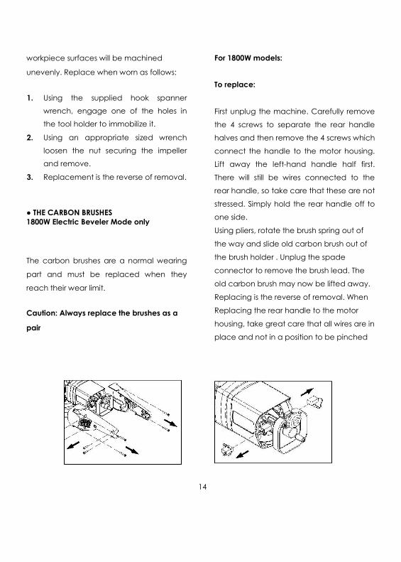
workpiece surfaces will be machined
unevenly. Replace when worn as follows: 1. Using the supplied hook spanner
wrench, engage one of the holes in
the tool holder to immobilize it. 2. Using an appropriate sized wrench
loosen the nut securing the impeller
and remove. 3. Replacement is the reverse of removal. ● THE CARBON BRUSHES 1800W Electric Beveler Mode only The carbon brushes are a normal wearing
part and must be replaced when they
reach their wear limit. Caution: Always replace the brushes as a
pair
For 1800W models: To replace: First unplug the machine. Carefully remove
the 4 screws to separate the rear handle
halves and then remove the 4 screws which
connect the handle to the motor housing.
Lift away the left-hand handle half first.
There will still be wires connected to the
rear handle, so take care that these are not
stressed. Simply hold the rear handle off to
one side. Using pliers, rotate the brush spring out of
the way and slide old carbon brush out of
the brush holder . Unplug the spade
connector to remove the brush lead. The
old carbon brush may now be lifted away.
Replacing is the reverse of removal. When
Replacing the rear handle to the motor
housing, take great care that all wires are in
place and not in a position to be pinched
14

when it is retightened. ●If the replacement of the power supply
cord is necessary, this has to be done by
the manufacturer or their agent in order to
avoid a safety hazard. 15

WIRING (1800W Mode) 17
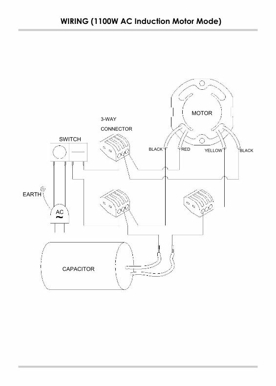
WIRING (1100W AC Induction Motor Mode)
MOTOR 3-WAY
CONNECTOR
SWITCH BLACK RED YELLOW BLACK
EARTH
AC
CAPACITOR


PARTS LIST (1800W Mode)
No. Parts Name Q'TY No. Parts Name Q'TY
1 POWER SUPPLY CABLE 1 34 SPIRAL BEVEL GEAR M1.5 47T 1
2 CORD ARMOR 1 35 INTERNAL CIRCLIP R-47 1
3 CABLE CLIP 1 36 EXTERNAL CIRCLIP S-20 1
4 SCREW M4 x 14 2 37 BALL BEARING 6204-2RS 1
5 SWITCH LOCK-ON 1 38 WOODRUFF KEY 5 x 5 x 12 1
6 SCREW M4 x 30 6 39 SPINDLE 1
7 SCREW M4 x 16 5 40 INNER SUPPORT BARREL 1
8 RIGHT HANDLE COVER 1 41 SOCKET CAP SCREW M5 x 25 4
9 LEFT HANDLE COVER 1 42 DIAL RING 1
10 ELECTRONICS UNIT 1 43 SET SCREW M4 x 6 1
11 THUMB WHEEL 1 44 SUPPORT DECK BODY 1
12 SCREW M4 x 8 4 45 LOCK KNOB M5 x 16 2
13 BRUSH SPRING 2 46 SUPPORT DECK PLATE 1
14 CARBON BRUSH 7 x 11 2 47 SCREW M4 x 12 3
15 CARBON BRUSH HOLDER 7 x 11 2 48 SCREW M4 x 8 5
16 SCREW M4 x 10 1 49 INDEXABLE CARBIDE INSERT 5
17 FLAT WASHER ø4 x ø10 x 1 1 50A TOOL HOLDER 45° 45° 1
18 PLASTIC WASHER ø4 x ø11 x 1 1 50B TOOL HOLDER 30° ( Optional) 30° 1
19 PICKUP MAGNET ø8 x ø15 x 5 1 50C TOOL HOLDER 37.5° ( Optional) 37.5° 1
20 SPACER ø8 x ø12 x 10.5 1 51 SPACER ø8.1 x ø14 x 5.5 1
21 MOTOR HOUSING 1 52 INTERNAL CIRCLIP R-22 1
22 STATOR 1 53A IMPELLER 45° 45° ø27 x 14.5 1
23 SCREW M5 x 60 2 53B IMPELLER 30° ( Optional) 30° ø32 x 14.5 1
24 FAN SHROUD 1 53C IMPELLER 37.5° ( Optional) 37.5° ø29.7 x 14.5 1
25 BALL BEARING 608 zz 2 54 SHOULDER BOLT M6 1
26 ARMATURE 1 55 SCREW M5 x 15 2
26-1 SPIRAL BEVEL PINION M1.5 x 12T 1 56 MOTOR REST 1
27 BALL BEARING 6001-2RU 1 57~61 N/A -
28 GEAR CASE 1 62 TORX WRENCH T15 1
29 SPINDLE LOCK BUTTON 1 63 HOOK SPANNER WRENCH 1
30 WASHER ø6 x ø13 x 1 4 64 SPINDLE LOCK BAR 1
31 SPINDLE LOCK 1 65 FRONT HANDLE 1
32 SCREW M5 x 40 4 66 SOCKET CAP SCREW M8 2
33 NEEDLE BEARING HK 0810 1 67 SPRING WASHER M5 4 23

EXPLODED VIEW (1100W AC Induction Motor Mode) 37
36
35
34
17
33
21 20
19 18
14
13 11
10 09
12 11
10 09
08 07
38
39 40 23
41 24
22
06
05 04
03
15 16 17
61
32
31
30
29
42 43
28
27
26 44
25 45
47
48 46
49
50
51
52
53
55
54
50
56
57
02 50
01
58 59 60
24

PARTS LIST (1100W AC Induction Motor Mode)
No. Parts Name Q'TY No. Parts Name Q'TY
1 FRONT HANDLE 1 32 SCREW M5 x 8 4
2 SCREW M14 x 25 4 33 CONTROL BOX 1
3 INNER COVER 1 34 CAPACITOR 400VAC, 20UF
4 SCREW M10 x 20 4 230V / 250VAC, 20UF 110V 1
5 FLAT WASHER Ø10 x Ø23 x 2 4 35 SWITCH PANEL 1
6 DEPTH ADJUST NUT 1 36 SCREW M4 x 10 4
7 HEX. NUT M16 x P2.0 1 37 SWITCH KJD17-AC230V 1
8 DISC SPRING Ø16 x Ø30 x 1.5 1 38 TERMINAL 3
9 MILLING DISC 2 39 CABLE GLAND SB7R-3 1
10 HEADLESS SCREW M6 x 6 12 40 CABLE GLAND SB8R-3 1
11 CARBIDE MILLING PLATE 12 41 POWER SUPPLY CABLE 1
12 INTERMEDIATE WASHER Ø20 x Ø35 x 3.5 1 42 WIRE LEAD 2
13 MILLING RECEIVER 1 43 WIRE SHEATH 6mmx15cm 1
14 BEARING PLATE 1 44 HANDLE 1
15 DEPTH INDICATOR 1 45 SCREW M8 x 40 2
16 FLAT WASHER Ø4 x Ø10 x 1 1 46 SPRING WASHER M8 2
17 SCREW M4 x 10 5 47 RUBBER FOOT 30L 4
18 CABLE GLAND 1 48 FLAT WASHER Ø6 x Ø13 x 1 4
19 BALL BEARING 6004-2RS 1 49 SCREW M6 x 30 4
20 ARMATURE 1 50 SCREW M6 x 16 16
21 WOODRUFF KEY 6 x 6 x 30 1 51 ROLLER AXLE 2
22 STATOR 1 52 GUIDING WHEEL 2
23 SCREW M4 x 8 1 53 WHEEL STUB AXLE 4
24 SUN WASHER M4 1 54 SLEWING SEGMENT (L) 1
25 MOTOR HOUSING 1 55 SLEWING SEGMENT (R) 1
26 BALL BEARING 6202 zz 1 56 HORIZONTAL TABLE PLATE 1
27 WAVE WASHER 6202 1 57 VERTICAL TABLE PLATE 1
28 MOTOR END CASTING 1 58 L-WRENCH M3 1
29 SCREW M5 x 200 4 59 WRENCH M24 x M27 1
30 FAN 1 60 WRENCH M32 1
31 FAN COVER 1 61 L-WRENCH M8 1

Reference standards (CE Declaration of Conformity)
!"#$%&"'$ )**+,-.,/012 345"% &$%67"%48 #$9:"#$;$7&5 <=# 8=>?'=8&4@$ $8$%&#"%48 $9:"A;$7&
!"#$%&"'$ )**B,C*D,/012 /8$%&#=;4@7$&"% %=;A4&"E"8"&F
!"#$%&"'$ -D,GH,/012 I4<$&F =< ;4%6"7$#F – 345"% #$9:"#$;$7&5
/J KIL C)C**?)2 I4<$&F =< ;4%6"7$#F – M$%67"%48 A#"7%"A8$5
/J KIL CGD.H2 I4<$&F =< ;4%6"7$#F – I4<$&F N"5&47%$5 &= A#$'$7& 64O4#N O=7$5 E$"7@ #$4%6$N EF :AA$# 47N 8=>$# 8";E5
/J -.G2 I4<$&F =< ;4%6"7$#F – P$7$#48 #$9:"#$;$7&5 <=# &6$ N$5"@7 47N %=75&#:%&"=7 =< <"Q$N 47N ;='4E8$ @:4#N5
/J +*)*B?C2 I4<$&F =< ;4%6"7$#F – /8$%&#"%48 $9:"A;$7& =< ;4%6"7$5
/J +C***?+?G2 /8$%&#=;4@7$&"% %=;A4&"E"8"&F – P$7$#"% 5&47N4#N5 – /;"55"=7 5&47N4#N <=# #$5"N$7&"48R %=;;$#%"48 47N 8"@6&?"7N:5&#"48 $7'"#=7;$7&5
MAQUINARIA NOGVAL S.L.C. Borges Blanques nº 38P.I. La Borda08140 Caldes de Montbui (Barcelona) Tel.: 0034 93 865 35 68E-mail: [email protected]