installation & technical information · 1 1 off 60 times/min (4) 60 times/min (5) 60 times/min...
TRANSCRIPT

18
9.0 End of Line Monitoring
An End of Line monitoring Diode or an End of Line monitoring Resistor can be connected across the 24V+ and 0 terminals. Resistor values for the End of Line will be determined by the customer with a minimum value of 1.2kΩ
10.0 Maintenance
Little or no maintenance is required during the normal working life of the product. The Moflash Exd enclosures are resistant to most acids, alkalis and chemicals and have been designed to withstand severe weather conditions. However it is suggested that to avoid the possibility of a potential electrostatic charge build up, the exterior of the product is periodically wiped down with a clean damp cloth. At this point a visual inspection is recommended to ensure that the product is in good working order and no damage has been sustained during its normal operation.
SAFETY WARNING
In the case of Anti Static and UV Resistant GRP, the painting of the enclosure surface has been processed specially. To maintain the product to be Anti Static, extra normal painting is not allowed.
If any failure occurs but not caused by human factor, the product can be returned to Moflash for free repair or replacement during the warranty.
11.0 Conditions for Safe Usage
i) This apparatus is suitable to be used only in ambient temperature as stated below:
ii) Do not paint or change the surface finish of the unit. The coating applied by the manufacturer is Anti-Static & UV Stable.
iii) Repairs of the flameproof joints must be made in compliance with the structural specifications provided by the manufacturer. Repairs must not be made on the basis of values specified in tables 1 and 2 of EN/IEC 60079-1.
Moflash part code BC150-S00521-Issue 4
BC150 Series - (Explosion Proof Beacon)Glass Reinforced PolyesterVISUAL SIGNALLING DEVICES
Type Ambient TempBC150 -400C to +700C
Website: www.moflash.com Email: [email protected]
INSTALLATION & TECHNICAL INFORMATION PLEASE READ PRIOR TO INSTALLATION
APPROVALS ANDCONFORMITIES

72
1.0 Introduction
The BC150 range is certified for use and installation in Zone 1 and Zone 2 with gas groups IIA, IIB, IIC, also Zones 21 and 22 for Dust. The unit carries a temperature classification of T4~T6. It especially applies to Oil & Gas, Offshore Platform, Chemical, Petrochemical, Refinery and Marine Industries etc. Enclosure material is UV and corrosion resistance GRP (Glass Reinforced Polyester). Moflash also recommends anti static GRP material for your consideration. Different flash or rotary rate can be adjusted from unique design. Three working statuses; flash type, rotary type and steady type are available (LED). There are two types of beacon (Xenon type and LED type) available for the customer.
2.0 Explosion Proof Labelling
All products have a rating label with the following important information:Product order no: eg BC150RX05DCNNNAR(Refer to the datasheet for product order selection)
Input voltage: 12-48v Dc or 100-240v Ac (50/60 Hz), <25W
Code: Ex d IIC T4~ T6 Gb, Ex tb IIIC T1350C~T850C IP66
Nemko ATEX Certificate No: Nemko 14ATEX 1011X
ATEX Mark:
IECEx Certificate: IECEx-NEM 14.0007X
Gas Group and Category: II 2GD
CE Mark: Mark No: 0518
Warning: DO NOT OPEN WHEN AN EXPLOSIVE GAS ATMOSPHERE IS PRESENT
Finished product serial no (Include date of construction)ie. BC150-0201080001
BC150-GRP Beacon & Light, Day-02, Month-01, Year-08,Product Serial Number-0001
8.0 Cable Gland
Only cable glands approved for Exd applications can be used with Moflash Explosion Proof Products, these must be suitable for the type of cable being used and also meet the requirements of the Exd flameproof installation standard EN 60079-14.
SAFETY WARNING
If units are used at high ambient temperatures, ie over +400C then the cable entry temperature may exceed +700C and therefore suitable heat resisting cable glands must be used, with a rated service temperature of at least 950C.
If a high IP (Ingress Protection) rating is required, a suitable sealing washer must be fitted under the cable gland. Any unused cable entry holes must be closed with an Exd flameproof blanking plug, which must be suitably approved for the installation requirements.
The gland accessories below offer a wide selection to cover most Ex environments
S1/S2 DIP Switch
S1=OFFS2=OFF
S1=ONS2=OFF
S1=OFFS2=ON
S1=ONS2=ON
1st DIP 2nd DIP Alarm Stage 1 Alarm Stage 2 Alarm Stage 3 Alarm Stage 4
0 0 OFF 60 times/min (1) 90 times/min (1) 120 times/min (1)
1 0 OFF 60 times/min (2) 60 times/min (3) 60 times/min (4)
0 1 OFF 60 times/min (3) 60 times/min (4) 60 times/min (5)
1 1 OFF 60 times/min (4) 60 times/min (5) 60 times/min (6)
Table 2 - Xenon Beacon Frequency and Status SelectionAll values in ( ) are the numbers of flashes per time
Gland and Plug Options
50200: M20 E1EX Nickel Plated Brass Gland 50210: M20 E1EX Stainless Steel Gland50201: M20 A2EX Nickel Plated Brass Gland 50211: M20 A2EX Stainless Steel Gland50202: M20 E1EX-QS Nickel Plated Brass Gland 50212: M20 E1EX-QS Stainless Steel Gland50203: M20 A2EX Quick Stop Nickel 50213: M20 A2EX Quick Stop50204: M20 Nickel Plated Brass Stopping Plug 50214: M20 Stainless Steel Stopping Plug
36
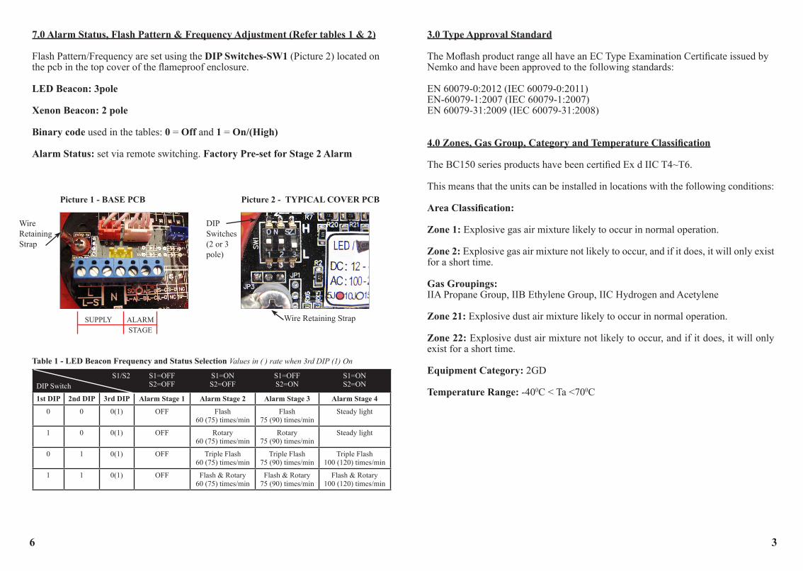
7.0 Alarm Status, Flash Pattern & Frequency Adjustment (Refer tables 1 & 2)
Flash Pattern/Frequency are set using the DIP Switches-SW1 (Picture 2) located on the pcb in the top cover of the flameproof enclosure.
LED Beacon: 3pole
Xenon Beacon: 2 pole
Binary code used in the tables: 0 = Off and 1 = On/(High)
Alarm Status: set via remote switching. Factory Pre-set for Stage 2 Alarm
Picture 1 - BASE PCB
S1/S2 DIP Switch
S1=OFFS2=OFF
S1=ONS2=OFF
S1=OFFS2=ON
S1=ONS2=ON
1st DIP 2nd DIP 3rd DIP Alarm Stage 1 Alarm Stage 2 Alarm Stage 3 Alarm Stage 4
0 0 0(1) OFF Flash 60 (75) times/min
Flash75 (90) times/min
Steady light
1 0 0(1) OFF Rotary 60 (75) times/min
Rotary75 (90) times/min
Steady light
0 1 0(1) OFF Triple Flash 60 (75) times/min
Triple Flash75 (90) times/min
Triple Flash 100 (120) times/min
1 1 0(1) OFF Flash & Rotary 60 (75) times/min
Flash & Rotary 75 (90) times/min
Flash & Rotary 100 (120) times/min
Table 1 - LED Beacon Frequency and Status Selection Values in ( ) rate when 3rd DIP (1) On
Picture 2 - TYPICAL COVER PCB
WireRetainingStrap
SUPPLY ALARM STAGE
Wire Retaining Strap
DIP Switches (2 or 3 pole)
3.0 Type Approval Standard
The Moflash product range all have an EC Type Examination Certificate issued by Nemko and have been approved to the following standards:
EN 60079-0:2012 (IEC 60079-0:2011)EN-60079-1:2007 (IEC 60079-1:2007)EN 60079-31:2009 (IEC 60079-31:2008)
4.0 Zones, Gas Group, Category and Temperature Classification
The BC150 series products have been certified Ex d IIC T4~T6. This means that the units can be installed in locations with the following conditions:
Area Classification:
Zone 1: Explosive gas air mixture likely to occur in normal operation.
Zone 2: Explosive gas air mixture not likely to occur, and if it does, it will only exist for a short time. Gas Groupings: IIA Propane Group, IIB Ethylene Group, IIC Hydrogen and Acetylene
Zone 21: Explosive dust air mixture likely to occur in normal operation.
Zone 22: Explosive dust air mixture not likely to occur, and if it does, it will only exist for a short time.
Equipment Category: 2GD
Temperature Range: -400C < Ta <700C

54
5.0 Installation
General Requirement
The product must be installed in accordance with the latest EN60079-0 and EN60079-1 specification or the equivalent IEC specification. Product installation must be carried out in accordance with any local codes that may apply and should only be carried out by a competent electrical engineer.
Location
The location of the unit should be chosen with due regard to the area over which the beacon warning signal must be visible/audible. The unit should only be fixed to services that can support the weight of the unit.
Mounting
The unit should be mounted on a vertical surface using four fixing holes in the base. The fixing holes are designed to fit M8 Allen Screw only. Use of stainless steel fastener is recommended by Moflash. The beacon can be operated in any attitude. If you need a mounting plate, please contact Moflash to ask for the mounting plate installation drawing (see diagram 1).
150.
0
150.0
120.0
120.
0
Ø150.0
4-Ø9.0FIX HOLE
150.
0
212.0120.0
22.0
60.0CABLE ENTRIES (x4)
POWER OUT POWER IN
6 M5 Socket Screw
L N
E
L N
E
DIP Switch
DIP Switch
1 2 3
LED PCB
XENON PCB
ON
L SO S2 N S1
L SO S2 N S1
1 2
ON
150.
0
150.0
120.0
120.
0
Ø150.0
4-Ø9.0FIX HOLE
150.
0
212.0120.0
22.0
60.0CABLE ENTRIES (x4)
POWER OUT POWER IN
6 M5 Socket Screw
L N
E
L N
E
DIP Switch
DIP Switch
1 2 3
LED PCB
XENON PCB
ON
L SO S2 N S1
L SO S2 N S1
1 2
ON
6.0 Wiring
General Requirement
Moflash recommends that all cables and cores should be fully identified (suggest using cable from 2.0 to 2.5 mm²). Ensure that all nuts, bolts and screws are secured. Ensure that only the right and certified cable glands are used and earthed correctly. Ensure that only the right and certified stopping plugs are used to blank off unused gland entry points. In order to maintain the IP rating of the product, we recommend SS316 for this application.
Cable Connection: The Supply and Alarm Status cable is connected to the terminals located in the flameproof enclosure base (Picture 1 and separate wiring drawing). For AC Supply –to terminals marked L & N.Terminals provide loop in loop out facility.
For DC Supply - connect “+” to L and “0” to N. Alarm Status - to terminals marked ‘S0’ (common) & ‘S1’, ‘S2’(Refer clause 7.0 - see tables).
Do not connect Ac or Dc to terminals S0, S1, S2
Removal of Top Cover (Beacon Component)Unscrew the six (6) M5 retained Hexagon socket head screws. Twist the cover gently clockwise and anti-clockwise, whilst pulling away from the body, keeping the cover parallel to the body until it comes free. This will allow the cover to hang on its retaining strap. Before replacing the cover, check that the flameproof joints are clean and not damaged, the gasket is still retained in its groove.
Diagram 1