installation progress of the laser-based synchronization ......mar 04, 2010 · free-space optics...
TRANSCRIPT

Installation Progress of the Laser-based SynchronizationSystem at FLASH.
Overview, Experiences, Performance and Outlook
Sebastian Schulz1,2 on behalf of the FLASH LbSyn Team
1Institute of Experimental PhysicsHamburg University, Germany
2Deutsches Elektronen-Synchrotron (DESY), Hamburg, Germany
48th ICFA Advanced Beam Dynamics Workshop on Future Light SourcesMarch 1 – 5, 2010
S. Schulz (Hamburg U, DESY) FLASH Optical Synchronization FLS Workshop 2010 1 / 25

Outline.
1 Introduction and Overview
2 Progress and Results of Selected SubsystemsMaster Laser OscillatorFiber LinksLaser-to-Laser SynchronizationInfrastructure and Electronics
3 Latest DevelopmentPhotoinjector Laser Synchronization
4 Summary and Outlook
S. Schulz (Hamburg U, DESY) FLASH Optical Synchronization FLS Workshop 2010 2 / 25
Introduction and Overview
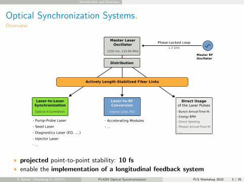
Optical Synchronization Systems.Overview
• projected point-to-point stability: 10 fs• enable the implementation of a longitudinal feedback system
S. Schulz (Hamburg U, DESY) FLASH Optical Synchronization FLS Workshop 2010 3 / 25

Introduction and Overview
The Laser-based Synchronization System at FLASH.Layout, Implementation and Upgrades
RF gun
L2RF
ACC1 ACC39L2RF
L2RF
BAM EBPM
ACC2 ACC3L2RF
EO/THzlaser
EO photon beam
target
ACC4 ACC6 ACC7ACC5L2RF
injectorlaser 1
HHG
seedlaser
BAM
BAMEO/THz
BAMseedingundulators SASE undulators
bypass
OXC
OXCOXC
OXC
16-port FSD unitEDFAs
master laseroscillator EDFLFL
RL
L2RF
FL
master laseroscillator SESAM
dump
BAMEBPMBCM BCM
Yb berlaser
FL
FL
FL
RL
FL
pump-probelaser
OXCFLadd. diag FL
FL
FL
FL
FL
• last user run (till September 2009)
→ MLO with distribution and 4 fiber links, 3 BAMs, 1 EBPM (3 front-ends),→ standard BCMs, EO with Ti:sapphire laser
S. Schulz (Hamburg U, DESY) FLASH Optical Synchronization FLS Workshop 2010 4 / 25

Introduction and Overview
The Laser-based Synchronization System at FLASH.Layout, Implementation and Upgrades
RF gun(exchanged)
L2RF
ACC1 ACC39L2RF
L2RF
BAM EBPM
ACC2 ACC3L2RF
EO/THzlaser
EO photon beam
target
ACC4 ACC6 ACC7ACC5L2RF
injectorlaser 2
HHG
seedlaser
BAM
BAMEO/THz
BAMseedingundulators SASE undulators
bypass
OXC
OXCOXC
OXC
16-port FSD unitEDFAs
master laseroscillator EDFLFL
RL
L2RF
FL
master laseroscillator SESAM
dump
BAMEBPM
L2RF
BCM
Yb FLOrange
EO
EOBCM
Yb berlaser
FL
FL
FL
FL
FL
FLRL
FL
pump-probelaser
OXC L2RF
FLadd. diag FLFL
• last user run (till September 2009)→ MLO with distribution and 4 fiber links, 3 BAMs, 1 EBPM (3 front-ends),
→ standard BCMs, EO with Ti:sapphire laser
• after the FLASH upgrade (just finished, now in commissioning phase). . .
S. Schulz (Hamburg U, DESY) FLASH Optical Synchronization FLS Workshop 2010 4 / 25

Introduction and Overview
The Laser-based Synchronization System at FLASH.Layout, Implementation and Upgrades
RF gun(exchanged)
L2RF
ACC1 ACC39L2RF
L2RF
BAM EBPM
ACC2 ACC3L2RF
EO/THzlaser
EO photon beam
target
ACC4 ACC6 ACC7ACC5L2RF
injectorlaser 2
HHG
seedlaser
BAM
BAMEO/THz
BAMseedingundulators SASE undulators
bypass
OXC
OXCOXC
OXC
16-port FSD unitEDFAs
master laseroscillator EDFLFL
RL
L2RF
FL
master laseroscillator SESAM
dump
BAMEBPM
L2RF
BCM
Yb FLOrange
EO
EOBCM
Yb berlaser
FL
FL
FL
FL
FL
FLRL
FL
pump-probelaser
OXC L2RF
FLadd. diag FLFL
• last user run (till September 2009)→ MLO with distribution and 4 fiber links, 3 BAMs, 1 EBPM (3 front-ends),
→ standard BCMs, EO with Ti:sapphire laser
• upgraded MLO and distribution, 3 more fiber links, 1 new BAM, 1 newEBPM, new BCM setups, new EO station, new OXC-IL2, improvedinfrastructure, and more
S. Schulz (Hamburg U, DESY) FLASH Optical Synchronization FLS Workshop 2010 4 / 25

Progress and Results of Selected Subsystems Master Laser Oscillator
Master Laser Oscillator I.
Overview and Current Status
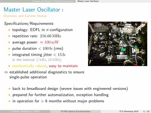
Specifications/Requirements
• topology: EDFL in σ-configuration
• repetition rate: 216.66MHz
• average power: ≈ 100mW
• pulse duration < 100 fs (rms)
• integrated timing jitter < 15 fsin the interval [1 kHz, 10MHz]
• mechanically robust, easy to maintain
⇒ established additional diagnostics to ensure⇒ single-pulse operation
L/4
L/2
L/2coll.
collimator
WDM
L/4
isolator
PBC
L/4
piezo mirror on
motorized stage
Er-doped
fiber
L/2
PBC
PBCL/2
photo diode
to free-space
distribution
pump
combiner
980 nm
pump
diodes
autocorrelator
OSA,
amplitude mon.
• back to breadboard design (severe issues with engineered versions)
• prepared for further automatization, exception handling
• in operation for > 6 months without major problems
S. Schulz (Hamburg U, DESY) FLASH Optical Synchronization FLS Workshop 2010 5 / 25
Progress and Results of Selected Subsystems Master Laser Oscillator
Master Laser Oscillator I.
Overview and Current Status
Specifications/Requirements
• topology: EDFL in σ-configuration
• repetition rate: 216.66MHz
• average power: ≈ 100mW
• pulse duration < 100 fs (rms)
• integrated timing jitter < 15 fsin the interval [1 kHz, 10MHz]
• mechanically robust, easy to maintain
⇒ established additional diagnostics to ensure⇒ single-pulse operation
• back to breadboard design (severe issues with engineered versions)
• prepared for further automatization, exception handling
• in operation for > 6 months without major problems
S. Schulz (Hamburg U, DESY) FLASH Optical Synchronization FLS Workshop 2010 5 / 25

Progress and Results of Selected Subsystems Master Laser Oscillator
Master Laser Oscillator II.
Some Recent Results
−180
−160
−140
−120
−100
−80
−60
−40
SSB
phas
e no
ise
L ! (
dBc/
Hz)
102 103 104 105 106 107 1080
2
4
6
8
10
12
14
inte
grat
ed ti
min
g jit
ter
(fs)
offset frequency (Hz)
free−running, P = 10.8 mW −> u2t photo diode @ monitor port, Vbias = 7.00 V, thick RF [email protected] GHz = 10.4 dBm, att. = 10 dB, 1000 corr., no avg., open housing
integr. timing jitter = 11.5 fs
• integrated timing jitter 11.5 fsin the interval [1 kHz, 10MHz]
S. Schulz (Hamburg U, DESY) FLASH Optical Synchronization FLS Workshop 2010 6 / 25
Progress and Results of Selected Subsystems Master Laser Oscillator
Master Laser Oscillator II.
Some Recent Results
50 100 150 2000.99
0.995
1
1.005
1.01
time (h)
MLO
2 re
lativ
e op
tical
pow
er
peak−to−peak = 0.0180, standard deviation = 0.0039
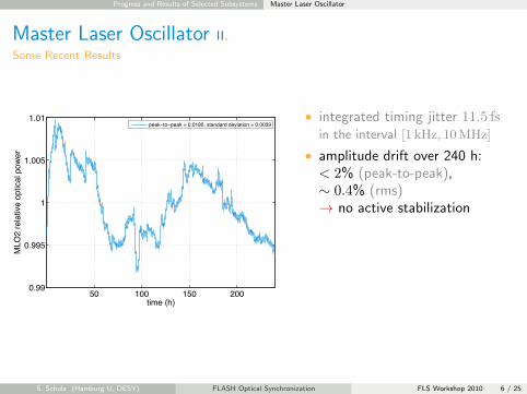
• integrated timing jitter 11.5 fsin the interval [1 kHz, 10MHz]
• amplitude drift over 240 h:< 2% (peak-to-peak),∼ 0.4% (rms)→ no active stabilization
S. Schulz (Hamburg U, DESY) FLASH Optical Synchronization FLS Workshop 2010 6 / 25

Progress and Results of Selected Subsystems Master Laser Oscillator
Master Laser Oscillator II.
Some Recent Results
−800 −600 −400 −200 0 200 400 600
0
0.1
0.2
0.3
0.4
0.5
0.6
0.7
0.8
0.9
1
delay (fs)
auto
−co
rrel
atio
n si
gnal
(a.
u.)
measured datataup = 87.3 fs
• integrated timing jitter 11.5 fsin the interval [1 kHz, 10MHz]
• amplitude drift over 240 h:< 2% (peak-to-peak),∼ 0.4% (rms)→ no active stabilization
• pulse duration τp = 87 fs, fromsech2(t/τp)-fit→ important for fiber link→ dispersion compensation
S. Schulz (Hamburg U, DESY) FLASH Optical Synchronization FLS Workshop 2010 6 / 25

Progress and Results of Selected Subsystems Master Laser Oscillator
Master Laser Oscillator III.
Alternative Concept: Investigation of a Commercial Laser System
Promising: OneFive ORIGAMI-15
• topology: unknown (SESAM, soliton)
• repetition rate: 216.66MHz
• average power: > 100mW
• pulse duration: τp < 150 fs
• integrated timing jitter < 5 fsin the interval [1 kHz, 10MHz]
• mechanically robust, easy to maintain(sealed housing, one button)
⇒ ordered custom system⇒ delivery/installation: April 2010
⇒ PSI enabled progress on direct conversion⇒ November 2009 – . . .
⇒ open questions: long-term stability, life-time
−170
−160
−150
−140
−130
−120
SSB PhaseNoise [dBc/Hz]
1k 10k 100k 1M 10M0
1
2
3
4
5
Timing Jitter [fs]
Frequency [Hz]
Origami / Direct−Conversion − RF Phase Noise: 4.3 fs
2.6 0.5 1 3.2
6 V, 13 mV, 1.5 GHz, 4.2 dBm
integrated timing jitter: 4.3 fs
S. Schulz (Hamburg U, DESY) FLASH Optical Synchronization FLS Workshop 2010 7 / 25
Progress and Results of Selected Subsystems Fiber Links
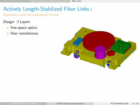
Actively Length-Stabilized Fiber Links I.
Experiences with the Engineered Version
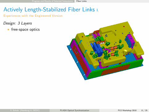
Design: 3 Layers
• free-space optics
• fiber installations
• electronics compartment
⇒ solved, taken into account for in first redesign (manufacturing now)
⇒ easy: dispersion compensated EDFA (between FSD and link box)⇒ advantageous: new pre-spliced DCF (lower insertion loss)
⇒ major redesign considerations in progress → end-of-year
S. Schulz (Hamburg U, DESY) FLASH Optical Synchronization FLS Workshop 2010 8 / 25
Progress and Results of Selected Subsystems Fiber Links
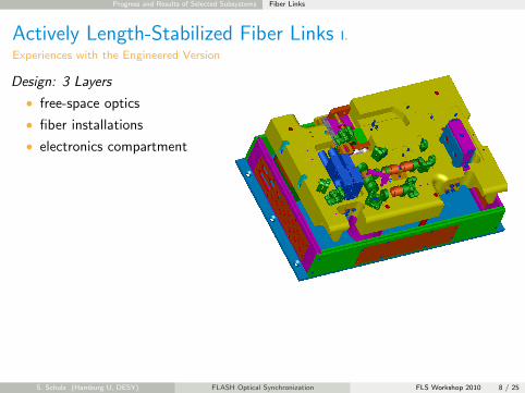
Actively Length-Stabilized Fiber Links I.
Experiences with the Engineered Version
Design: 3 Layers
• free-space optics
• fiber installations
• electronics compartment
⇒ solved, taken into account for in first redesign (manufacturing now)
⇒ easy: dispersion compensated EDFA (between FSD and link box)⇒ advantageous: new pre-spliced DCF (lower insertion loss)
⇒ major redesign considerations in progress → end-of-year
S. Schulz (Hamburg U, DESY) FLASH Optical Synchronization FLS Workshop 2010 8 / 25
Progress and Results of Selected Subsystems Fiber Links
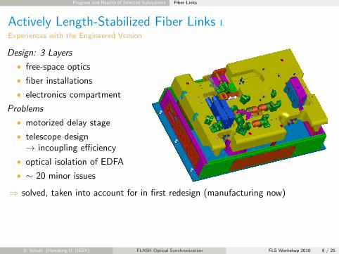
Actively Length-Stabilized Fiber Links I.
Experiences with the Engineered Version
Design: 3 Layers
• free-space optics
• fiber installations
• electronics compartment
Problems
• motorized delay stage
• telescope design→ incoupling efficiency
• optical isolation of EDFA
• ∼ 20 minor issues
⇒ solved, taken into account for in first redesign (manufacturing now)
⇒ easy: dispersion compensated EDFA (between FSD and link box)⇒ advantageous: new pre-spliced DCF (lower insertion loss)
⇒ major redesign considerations in progress → end-of-year
S. Schulz (Hamburg U, DESY) FLASH Optical Synchronization FLS Workshop 2010 8 / 25
Progress and Results of Selected Subsystems Fiber Links
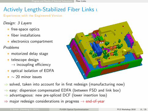
Actively Length-Stabilized Fiber Links I.
Experiences with the Engineered Version
Design: 3 Layers
• free-space optics
• fiber installations
• electronics compartment
Problems
• motorized delay stage
• telescope design→ incoupling efficiency
• optical isolation of EDFA
• ∼ 20 minor issues
⇒ solved, taken into account for in first redesign (manufacturing now)
⇒ easy: dispersion compensated EDFA (between FSD and link box)⇒ advantageous: new pre-spliced DCF (lower insertion loss)
⇒ major redesign considerations in progress → end-of-year
S. Schulz (Hamburg U, DESY) FLASH Optical Synchronization FLS Workshop 2010 8 / 25

Progress and Results of Selected Subsystems Fiber Links
Actively Length-Stabilized Fiber Links II.
Performance Example: Long-Term Drift
50 100 150 200
0.5
1
1.5
2
2.5
3
3.5
4
4.5
5
time (h)
fiber
link
in−
loop
tim
ing
jitte
r (f
s)
LINK09 in−loop timing jitter, mean = 0.91 fs, std = 0.08 fsLINK09 120 minute moving averageLINK15 in−loop, mean1 = 2.68 fs, std1 = 0.83 fs, mean2 = 1.11 fs, std2 = 0.28 fsLINK15 120 minute moving average
LINK09 → BAM UBC2
• ≈ 165m
• FRM link-end
• returning pulses τp = 115 fs
LINK15 → OXC EO
• ≈ 440m
• loop-mirror link-end
• returning pulses τp = 200 fs
• engineered fiber link boxes ensure reliable operation
• timing distribution to the femtosecond level over long periods
• out-of-loop measurement setup currently under consideration
S. Schulz (Hamburg U, DESY) FLASH Optical Synchronization FLS Workshop 2010 9 / 25

Progress and Results of Selected Subsystems Laser-to-Laser Synchronization
Laser-to-Laser Synchronization I.
Idea and First Implementation
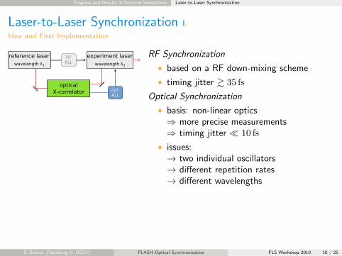
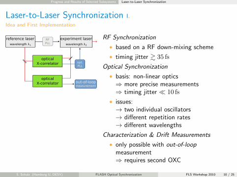
RF Synchronization
• based on a RF down-mixing scheme
• timing jitter & 35 fs
Optical Synchronization
• basis: non-linear optics⇒ more precise measurements⇒ timing jitter � 10 fs
• issues:→ two individual oscillators→ different repetition rates→ different wavelengths
Characterization & Drift Measurements
• only possible with out-of-loopmeasurement⇒ requires second OXC
S. Schulz (Hamburg U, DESY) FLASH Optical Synchronization FLS Workshop 2010 10 / 25
Progress and Results of Selected Subsystems Laser-to-Laser Synchronization
Laser-to-Laser Synchronization I.
Idea and First Implementation
RF Synchronization
• based on a RF down-mixing scheme
• timing jitter & 35 fs
Optical Synchronization
• basis: non-linear optics⇒ more precise measurements⇒ timing jitter � 10 fs
• issues:→ two individual oscillators→ different repetition rates→ different wavelengths
Characterization & Drift Measurements
• only possible with out-of-loopmeasurement⇒ requires second OXC
S. Schulz (Hamburg U, DESY) FLASH Optical Synchronization FLS Workshop 2010 10 / 25
Progress and Results of Selected Subsystems Laser-to-Laser Synchronization
Laser-to-Laser Synchronization II.
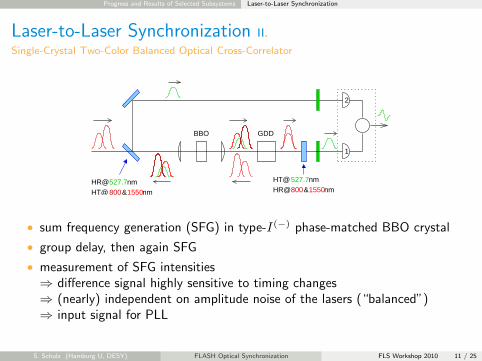
Single-Crystal Two-Color Balanced Optical Cross-Correlator
[email protected]&1550nmHT@
HT@HR@
527.7nm800&1550nm
2
1
BBO GDD
• sum frequency generation (SFG) in type-I(−) phase-matched BBO crystal
• group delay, then again SFG
• measurement of SFG intensities⇒ difference signal highly sensitive to timing changes⇒ (nearly) independent on amplitude noise of the lasers (“balanced”)⇒ input signal for PLL
S. Schulz (Hamburg U, DESY) FLASH Optical Synchronization FLS Workshop 2010 11 / 25
Progress and Results of Selected Subsystems Laser-to-Laser Synchronization
Laser-to-Laser Synchronization III.
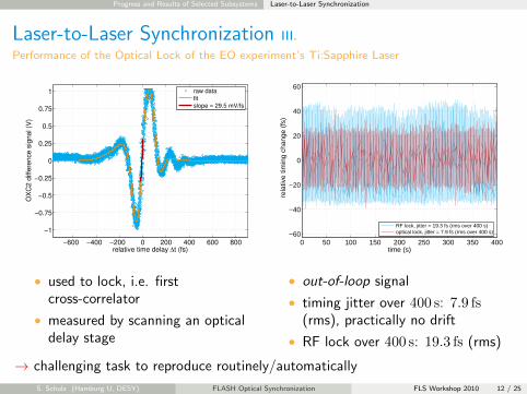
Performance of the Optical Lock of the EO experiment’s Ti:Sapphire Laser
−600 −400 −200 0 200 400 600 800
−1
−0.75
−0.5
−0.25
0
0.25
0.5
0.75
1
relative time delay ∆t (fs)
OX
C2 d
iffere
nce
sig
nal (
V)
raw data
Gaussian fit
slope = 29.5 mV/fsfit
• used to lock, i.e. firstcross-correlator
• measured by scanning an opticaldelay stage
0 50 100 150 200 250 300 350 400−60
−40
−20
0
20
40
60
time (s)
rela
tive
timin
g ch
ange
(fs
)
RF lock, jitter = 19.3 fs (rms over 400 s)optical lock, jitter = 7.9 fs (rms over 400 s)
• out-of-loop signal
• timing jitter over 400 s: 7.9 fs(rms), practically no drift
• RF lock over 400 s: 19.3 fs (rms)
→ challenging task to reproduce routinely/automatically
S. Schulz (Hamburg U, DESY) FLASH Optical Synchronization FLS Workshop 2010 12 / 25
Progress and Results of Selected Subsystems Infrastructure and Electronics
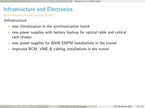
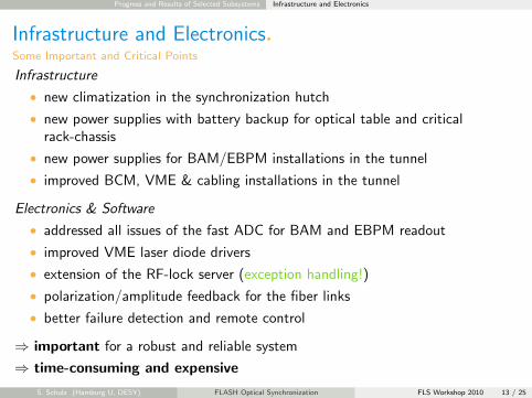
Infrastructure and Electronics.Some Important and Critical Points
Infrastructure
• new climatization in the synchronization hutch
• new power supplies with battery backup for optical table and criticalrack-chassis
• new power supplies for BAM/EBPM installations in the tunnel
• improved BCM, VME & cabling installations in the tunnel
Electronics & Software
• addressed all issues of the fast ADC for BAM and EBPM readout
• improved VME laser diode drivers
• extension of the RF-lock server (exception handling!)
• polarization/amplitude feedback for the fiber links
• better failure detection and remote control
⇒ important for a robust and reliable system
⇒ time-consuming and expensive
S. Schulz (Hamburg U, DESY) FLASH Optical Synchronization FLS Workshop 2010 13 / 25

Progress and Results of Selected Subsystems Infrastructure and Electronics
Infrastructure and Electronics.Some Important and Critical Points
Infrastructure
• new climatization in the synchronization hutch
• new power supplies with battery backup for optical table and criticalrack-chassis
• new power supplies for BAM/EBPM installations in the tunnel
• improved BCM, VME & cabling installations in the tunnel
Electronics & Software
• addressed all issues of the fast ADC for BAM and EBPM readout
• improved VME laser diode drivers
• extension of the RF-lock server (exception handling!)
• polarization/amplitude feedback for the fiber links
• better failure detection and remote control
⇒ important for a robust and reliable system
⇒ time-consuming and expensive
S. Schulz (Hamburg U, DESY) FLASH Optical Synchronization FLS Workshop 2010 13 / 25

Latest Development Photoinjector Laser Synchronization
Photoinjector Laser Synchronization I.
Motivation
New BAM upstream of First Chicane
• timing change:
δtbeam = Ggun δtgun +Glaser δtlaser
with
δtgun =δφgun
ωRFand δtlaser =
δφlaser
ωRF
• variation of gun and laser phase:
⇒ δtgun + δtlaser = 2.12 ps/deg
⇒ (32% + 68%)
• variation of RF-gun phase slope:
⇒ δtmax = 0.52 ps
⇒ RF-gun phase feed-forward or feedback⇒ requires arrival-time information of⇒ photoinjector laser pulses on cathode!
→ optical cross-correlator
−0.3 −0.2 −0.1 0 0.1 0.2 0.3−0.5
0
0.5
Change of Gun or Laser phase [deg]
Varia
tion
of a
rriva
l tim
e [p
s]
Laserdt/d! = 1.449 ps/degGundt/d! = 0.675 ps/deg
0 5 10 15 20 25 30−0.8
−0.6
−0.4
−0.2
0
0.2
0.4
Bunch number in macro pulse (10µs bunch spacing) [No #]
Aver
aged
arri
val t
ime
of b
unch
es [p
s]3.6 deg/ms4.2 deg/ms4.8 deg/ms5.4 deg/ms6.0 deg/ms
S. Schulz (Hamburg U, DESY) FLASH Optical Synchronization FLS Workshop 2010 14 / 25

Latest Development Photoinjector Laser Synchronization
Photoinjector Laser Synchronization II.
Prototype Implementation at FLASH
diode amplifier & pulse picker
flashlamps
LBOBBO
e
toroidRF gun
Nd:YLF osc.
manual shifter
photoinjector laser 2
1047 nm~ 15 nJ27 MHz
AD
C
OpticalX-Correlator
AD
CA
DC
DACDAC
IQ
13
.5 M
Hz
10
8 M
Hz
1.3
GH
z
MO
LO generation
controllerADCADC
MLO
20m SMF, PSOF, orRF-based FiberLink
synch. hutch
fR
LDD
EDFA
AD
C
controller
dispersion comp.
MD
R
L4,L2
delay line
MD
R
VME + Beckhoff or uTCA system
EOM AOM AOM
• MLO delivers precise timing information over an optical fiber• measuring timing jitter between PTO and reference on O(10 fs) level with
the optical cross-correlator• stabilize 1.3 GHz phase of the PTO’s EOM by a feed-forward algorithm or a
control loopS. Schulz (Hamburg U, DESY) FLASH Optical Synchronization FLS Workshop 2010 15 / 25
Latest Development Photoinjector Laser Synchronization
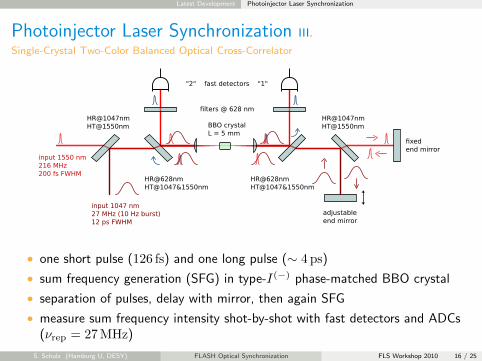
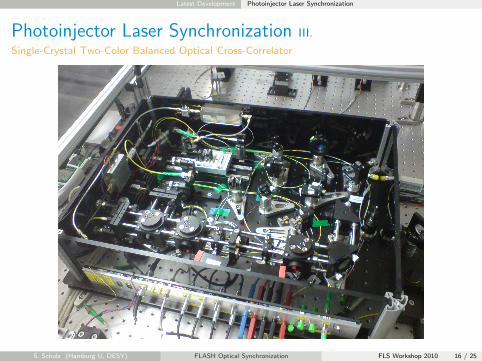
Photoinjector Laser Synchronization III.
Single-Crystal Two-Color Balanced Optical Cross-Correlator
HR@628nmHT@1047&1550nm
HR@628nmHT@1047&1550nm
BBO crystalL = 5 mm
input 1550 nm216 MHz200 fs FWHM
input 1047 nm27 MHz (10 Hz burst)12 ps FWHM
"2" fast detectors "1"
filters @ 628 nmHR@1047nmHT@1550nm
fixedend mirror
adjustableend mirror
HR@1047nmHT@1550nm
• one short pulse (126 fs) and one long pulse (∼ 4 ps)
• sum frequency generation (SFG) in type-I(−) phase-matched BBO crystal
• separation of pulses, delay with mirror, then again SFG
• measure sum frequency intensity shot-by-shot with fast detectors and ADCs(νrep = 27MHz)
S. Schulz (Hamburg U, DESY) FLASH Optical Synchronization FLS Workshop 2010 16 / 25
Latest Development Photoinjector Laser Synchronization
Photoinjector Laser Synchronization III.
Single-Crystal Two-Color Balanced Optical Cross-Correlator
S. Schulz (Hamburg U, DESY) FLASH Optical Synchronization FLS Workshop 2010 16 / 25

Latest Development Photoinjector Laser Synchronization
Photoinjector Laser Synchronization IV.
First Results
PRELIMINARY
• scan delay between MLO and PTO pulse → SFG in both directions of OXC
• measure for PTO pulse duration ⇒ 4.9 ps (rms)
• delay with mirror for second SFG not adjusted correctly
S. Schulz (Hamburg U, DESY) FLASH Optical Synchronization FLS Workshop 2010 17 / 25
Summary and Outlook
Summary and Outlook.Current Status of Upgrades to the Optical Synchronization System
1 many new components and subsystems
2 considerable progress towards a robust, reliable and engineered system
3 implementation of a longitudinal feedback
S. Schulz (Hamburg U, DESY) FLASH Optical Synchronization FLS Workshop 2010 18 / 25
Acknowledgements
Acknowledgements.
Thank you for your attention!
The FLASH LbSyn Team
M. K. Bock, M. Felber, P. Gessler, K. E. Hacker, F. Ludwig, H. Schlarb,B. Schmidt, S. Schulz, L. G. Wissmann
and its former membersV. Arsov, F. Loehl, A. Winter, J. Zemella
with its many collaborators, technicians and people of other groups
S. Schulz (Hamburg U, DESY) FLASH Optical Synchronization FLS Workshop 2010 19 / 25

Additional Slides: RF, L2L-Testsetup, FiberLink Principle... RF-Lock Electronics for Ti:Sapphire Lasers
RF-Lock Electronics for Ti:Sapphire Lasers.Extended RF Circuit with 81 MHz, 1.3 GHz and 9.1 GHz Phase-Detectors
S. Schulz (Hamburg U, DESY) FLASH Optical Synchronization FLS Workshop 2010 20 / 25
Additional Slides: RF, L2L-Testsetup, FiberLink Principle... Laser-to-Laser Synchronization
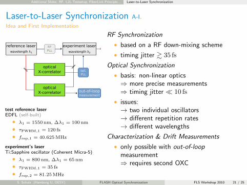
Laser-to-Laser Synchronization A-I.
Idea and First Implementation
test reference laserEDFL (self-built)
• λ1 = 1550 nm, ∆λ1 = 100 nm
• τFWHM,1 = 120 fs
• frep,1 = 40.625 MHz
experiment’s laserTi:Sapphire oscillator (Coherent Micra-5)
• λ1 = 800 nm, ∆λ1 = 65 nm
• τFWHM,1 = 35 fs
• frep,2 = 81.25 MHz
RF Synchronization
• based on a RF down-mixing scheme
• timing jitter & 35 fs
Optical Synchronization
• basis: non-linear optics⇒ more precise measurements⇒ timing jitter � 10 fs
• issues:→ two individual oscillators→ different repetition rates→ different wavelengths
Characterization & Drift Measurements
• only possible with out-of-loopmeasurement⇒ requires second OXC
S. Schulz (Hamburg U, DESY) FLASH Optical Synchronization FLS Workshop 2010 21 / 25

Additional Slides: RF, L2L-Testsetup, FiberLink Principle... Laser-to-Laser Synchronization
Laser-to-Laser Synchronization A-II.
Implementation using the FLASH EO Ti:Sapphire Laser System – Layout
S. Schulz (Hamburg U, DESY) FLASH Optical Synchronization FLS Workshop 2010 22 / 25
Additional Slides: RF, L2L-Testsetup, FiberLink Principle... Fiber Links
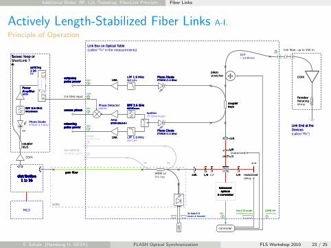
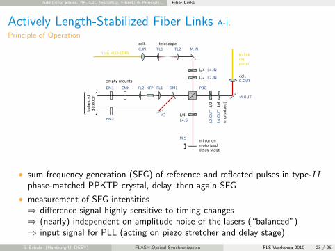
Actively Length-Stabilized Fiber Links A-I.
Principle of Operation
S. Schulz (Hamburg U, DESY) FLASH Optical Synchronization FLS Workshop 2010 23 / 25
Additional Slides: RF, L2L-Testsetup, FiberLink Principle... Fiber Links
Actively Length-Stabilized Fiber Links A-I.
Principle of Operation
• sum frequency generation (SFG) of reference and reflected pulses in type-IIphase-matched PPKTP crystal, delay, then again SFG
• measurement of SFG intensities⇒ difference signal highly sensitive to timing changes⇒ (nearly) independent on amplitude noise of the lasers (“balanced”)⇒ input signal for PLL (acting on piezo stretcher and delay stage)
S. Schulz (Hamburg U, DESY) FLASH Optical Synchronization FLS Workshop 2010 23 / 25
Additional Slides: RF, L2L-Testsetup, FiberLink Principle... Free-Space Distribution
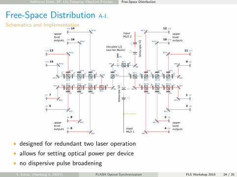
Free-Space Distribution A-I.
Schematics and Implementation
• designed for redundant two laser operation
• allows for setting optical power per device
• no dispersive pulse broadening
S. Schulz (Hamburg U, DESY) FLASH Optical Synchronization FLS Workshop 2010 24 / 25

Additional Slides: RF, L2L-Testsetup, FiberLink Principle... Free-Space Distribution
Free-Space Distribution A-I.
Schematics and Implementation
• designed for redundant two laser operation
• allows for setting optical power per device
• no dispersive pulse broadening
S. Schulz (Hamburg U, DESY) FLASH Optical Synchronization FLS Workshop 2010 24 / 25
Additional Slides: RF, L2L-Testsetup, FiberLink Principle... Free-Space Distribution
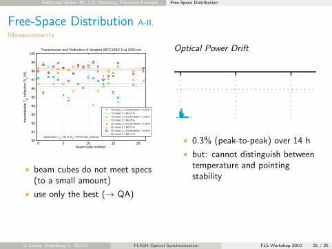
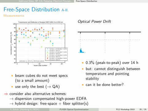
Free-Space Distribution A-II.
Measurements
0 5 10 15 2090
91
92
93
94
95
96
97
98
99
100
beam cube number
tran
smis
sion
Tp, r
efle
ctio
n R
s (%
)
Transmission and Reflection of Newport 05FC16BC.9 at 1550 nm
specification: Tp > 90 %, R
s > 99.5% (w/o surfaces)
Tp meas. 1, rms deviation = 0.96 %Tp mean 1 = 96.51 %Tp meas. 2, rms deviation = 1.08 %Tp mean 2 = 96.23 %Rs meas. 1, rms deviation = 0.39 %Rs mean 1 = 98.27 %Rs meas. 2, rms deviation = 0.66 %Rs mean 2 = 98.14 %
• beam cubes do not meet specs(to a small amount)
• use only the best (→ QA)
Optical Power Drift
• 0.3% (peak-to-peak) over 14 h
• but: cannot distinguish betweentemperature and pointingstability
• can it be done better?
⇒ consider also alternative schemes:⇒ → dispersion compensated high-power EDFA⇒ → hybrid design: free-space + fiber splitter(s)
S. Schulz (Hamburg U, DESY) FLASH Optical Synchronization FLS Workshop 2010 25 / 25
Additional Slides: RF, L2L-Testsetup, FiberLink Principle... Free-Space Distribution
Free-Space Distribution A-II.
Measurements
0 5 10 15 2090
91
92
93
94
95
96
97
98
99
100
beam cube number
tran
smis
sion
Tp, r
efle
ctio
n R
s (%
)
Transmission and Reflection of Newport 05FC16BC.9 at 1550 nm
specification: Tp > 90 %, R
s > 99.5% (w/o surfaces)
Tp meas. 1, rms deviation = 0.96 %Tp mean 1 = 96.51 %Tp meas. 2, rms deviation = 1.08 %Tp mean 2 = 96.23 %Rs meas. 1, rms deviation = 0.39 %Rs mean 1 = 98.27 %Rs meas. 2, rms deviation = 0.66 %Rs mean 2 = 98.14 %
• beam cubes do not meet specs(to a small amount)
• use only the best (→ QA)
Optical Power Drift
• 0.3% (peak-to-peak) over 14 h
• but: cannot distinguish betweentemperature and pointingstability
• can it be done better?
⇒ consider also alternative schemes:⇒ → dispersion compensated high-power EDFA⇒ → hybrid design: free-space + fiber splitter(s)
S. Schulz (Hamburg U, DESY) FLASH Optical Synchronization FLS Workshop 2010 25 / 25