installation & operating manual - webtrol · · 2016-04-04installation & operating manual...
TRANSCRIPT

Insta
llatio
n &
Op
era
tin
g M
an
ual
Centrifugal PumpStainless Steel Constructed
Congratulations On Your Choice
In Purchasing This Webtrol Pump
Its Quality is unsurpassed in material and workmanship and has been factory tested.
If properly installed, it will give many years of trouble free service.
25ISSC-M
9/06 Edition

Table Of Contents
Introduction
This manual was prepared to assist the installer and/or operator in understanding the proper method of
installing, operating and maintaining the SS series centrifugal pump. We recommend that you thoroughly
understand the proper installation and start-up procedures, prior to starting the pump. If these procedures are
followed, you will have years of trouble-free service.
1. Read these rules and instructions carefully. Failure to follow them could cause serious bodily injury and/orproperty damage.
2. Check your local codes before installing.
3. For maximum safety, this product should be connected to a grounded circuit equipped with a ground faultinterrupter device.
4. Before installing this product, have the electrical circuit checked by an electrician to make sure it is properly grounded.
5. Before installing or servicing your pump, BE CERTAIN pump power source is disconnected.
6. Make sure the line voltage and frequency of the electrical current supply agree with the motor wiring. If motor is dual voltage type, BE SURE it is wired correctly for your power supply.
7. Complete pump and piping system MUST be protected against below freezing temperature. Failure to doso could cause severe damage and voids the Warranty.
8. Do not run the pump dry. If it is, there will be damage to the pump seal.
9. Do not operate the pump in flammable and / or explosive atmosphere.
WARNINGRules For Safe Installation And Operation
Introduction 2
Performance / Specifications 3
Pump Inspection And Handling 3
Exploded View 4
Pre-Installation 5
Installation 5LocationMountingPiping
Electrical Connections 7-14
Start-up Procedure 14Shaft RotationValvesPrimingStartingFinal Inspection
Lubrication 15-16
Chemical Compatibility Chart 17
Trouble Shooting 18
- 2 -

TC Models FC Models
Performance And Specifications
Size: Suction TC70 1 1/4” NPT
TC120 1 1/4” NPT
TC200 1 1/2” NPT
Discharge All TC Models 1” NPT
HP Range: 1/3 HP to 1 1/2 HP - 1750 RPM
3/4 HP to 3 HP - 3450 RPM
Performance: Capacity - 5.5 GPM to 90 GPM
Head - 23 to 144 feet
Liquid - clean water
Liquid Temp. - 212°F
(250°F opt.)
Working Pressure - 125 PSI
Materials: Casing - 304 Stainless
Impeller - 304 Stainless
Shaft - Stainless
Mechanical Seal - Type 21
Motor: Nema 56J frame / 60 Hz
Built in overload protection
(single phase models)
Size: Suction FC32 2” ANSI
150 lb. ANSI FC40 2 1/2” ANSI
FC50 2 1/2” ANSI
Discharge FC32 1 1/4” ANSI
150 lb. ANSI FC40 1 1/2” ANSI
FC50 2” ANSI
HP Range: 1 HP to 2 HP - 1750 RPM
3 HP to 15 HP - 3450 RPM
Performance: Capacity - 13 GPM to 380 GPM
Head - 33 to 285 feet
Liquid Temp. - 212°F
(250°F opt.)
Working Pressure - 230 PSI
Materials: Casing - 304 Stainless
Impeller - 304 Stainless
Shaft - Stainless
Mechanical Seal - Type 21
Motor: Nema JM frame / 60 Hz
Pump Inspection And Handling
When receiving your pump, check to see if the shipment has been damaged in any way or if any parts seem to be missing. If so, note the damage or shortage on the bill of lading and the freight bill. Make any claims to thetransportation company immediately. Keep all packaging materials until the claim is resolved.
The Webtrol Stainless Steel Centrifugal pump should remain in the shipping carton until it is ready to be installed.
Do not drop or mishandle the pump prior to installation.
* Three phase motor only.
- 3 -

FC Series(Less Motor)
TC Series
Exploded Views
- 4 -

Locate the pump as close to the liquid source as possible, so that a short, direct suction pipe may be used.Place the unit so that it is readily accessible for service, maintenance and allows air to circulate freely aroundthe motor.
Mount pump in a dry location, on a secure base or foundation. This will prevent noise and vibration.
Piping should be stainless steel, rigid plastic or other suitable pipe that will not collapse or burst when exposedto suction and discharge pressure. The piping should be as free from turns and bends as possible, as elbowsand fittings greatly increase friction losses.
Pipes must line up and not be forced into position by unions. The suction pipe should be at least one size largerthan the suction inlet tapping, and have a minimum number of elbows and fittings to reduce friction losses. Also,the discharge piping should never be smaller than the pump tapping and should preferably be one size larger.
Piping should be independently supported near the pump so that no strain will be placed on the pump casing.Where any noise is objectionable, the pump should be insulated from the piping with rubber connections.
Installation
Pre-Installation
Pump is non-submersible. Keep motor dry at all times. Do not wash or immerse the motor.
Figure 1 - The normal position of the TC Series discharge is top vertical.
Normal Position
of Discharge
Discharge Rotated
90° Clockwise
Discharge Rotated
180° Clockwise
Discharge Rotated
270° Clockwise
Figure 1
Warning: Never run the pump dry. The internal running surfaces of the pump and mechanical seal requirewater lubrication for consistent operation. Allowing the pump to run dry will severely damage pumpand mechanical seal.
Do not pump chemicals or corrosive liquids with the pump unless they are compatible with the pump componentmaterials. Consult the chemical compatibility chart on page 15 of this manual or call Webtrol at (314) 631-9200for verification. Use with nonflammable liquids.
To avoid internal damage to the pump, do not operate with the water temperature above 212°F.
Pump must be full of liquid before operating. Do not pump dirty water or abrasive liquids. To do so, will causethe carbon seal face, and elastomers in the mechanical seal to wear and leak. Mechanical seal materials, com-patible with liquids containing abrasives, are available upon request.
Avoid air pockets in suction piping or air will accumulate at the high points, making priming difficult.
Do not allow the pump or any system component to freeze. To do so may damage the pump and void the warranty.
Note: The FC Series discharge can only be used in the normal position.
- 5 -

Figure 2 - Connection to a water tank which provides a gravity flow - flooded suction.
Figure 3 - Connection to a pressurized water system.
Figure 2
Figure 3
Figure 4
Figure 4 - Pump used on a suction lift application from a pond, cistern or container.
1. Install a service tee with a pipe plug, at the highest point in the suction line for initial priming
2. Install a foot valve at the end of the suction line.
3. Install a vacuum gauge in the suction line.
4. To retain water in the pump after turning the pump off, install a vacuum breaker in the discharge line. The horizontal run of pipe containing the vacuum breaker should be above the horizontal run of pipe containing the vacuum gauge.
- 6 -

Before wiring the pump to the power source, verify that the voltage of the motor matches the voltage of thepower supply. See motor nameplate. The supply voltage must be within + 10% of nameplate voltage. Incorrectvoltage can cause fire or seriously damage the motor and voids the warranty.
Wire motor according to the diagram shown on the motor nameplate. If the nameplate diagram differs from thewiring diagrams shown in this manual, follow the nameplate diagram.
Install ground wire and maintain this pump in compliance with the National Electrical Code (NEC) or theCanadian Electrical Code (CEC) and with all local codes and ordinances that apply. Consult your local buildinginspector for local code information.
The motors used on the TC Model pumps are commonly manufactured by Emerson, Baldor, Century, orBluffton. The motors used on the FC Models are manufactured by Baldor, U.S. Motor, A.O. Smith, (Century).
Both, 1 phase and 3 phase TC pump motors are factory wired for 230 volts. Motor frame is Nema 56J.
If the supply voltage for a 1 phase motor is 115 volts, refer to the motor wiring connections shown below to properly rewire the motor.
Electrical Connections - TC Pump
- 7 -
Emerson 3 Phase ODP Motor
Catalog Number See Figure HP
EE155 7 1/2
EE446 7 3/4
EE506 7 1
EE607 7 1 1/2
EE733 7 2
EE734 7 3
Emerson 1 Phase ODP Motor
Catalog Number See Figure HP
EU0502 5 1/2
EU0752 5 3/4
EU1002 5 1
EU1502 5 1 1/2
EU2002 5 2
EU3002 6 3*
Emerson Motors - TC Pump, Connection Diagrams
Figure 5
*The 3 HP - 1 Phase motor is dual voltage (208/230v) and cannot be connected to 115v.

*The 3 HP 1 Phase motor is single voltage (230v) andcannot be connected to 115v.
Century 1 Phase ODP TC Motor
Catalog Number See Figure HP
B633 8 3/4
B719 8 1
B737 8 1 1/2
B570 9 2
B781 10 3*
Century 3 Phase ODP TC Motor
Catalog Number See Figure HP
H446 11 3/4
H506 11 1
H607 11 1 1/2
H733 11 2
H734 11 3
Figure 8
Century Motors - TC Pump, Connection Diagrams
- 8 -
Emerson Motors - TC Pump, Connection Diagrams
Figure 7
Emerson Motors - TC Pump, Connection Diagram
Figure 6

- 9 -
Century Motors - TC Pump, Connection Diagrams
3 Phase Century Motors - TC Pump, Connection Diagrams
Figure 10
Figure 11
Century Motors - TC Pump, Connection Diagrams
Figure 9

Catalog Number See Figure HP
JL1306A 12 3/4
JL1309A 12 1
JL1313A 12 1 1/2
JL1317A 12 2
JL1323A 13 3*
Baldor 1 Phase ODP TC Motor
*The 3 HP 1 Phase motor is single voltage (230v)
and cannot be connected to 115v.
Catalog Number See Figure HP
JM3111 14 3/4
JM3115 14 1
JM3120 14 1 1/2
JM3155 14 2
JM3158 14 3
Baldor 3 Phase ODP TC Motor
Baldor Motors - TC Pump, Connection Diagrams
Figure 12
- 10 -
Baldor Motors - TC Pump, Connection Diagrams
Figure 13
3 Phase Baldor Motors - TC Pump, Connection Diagrams
Figure 14
- 11 -
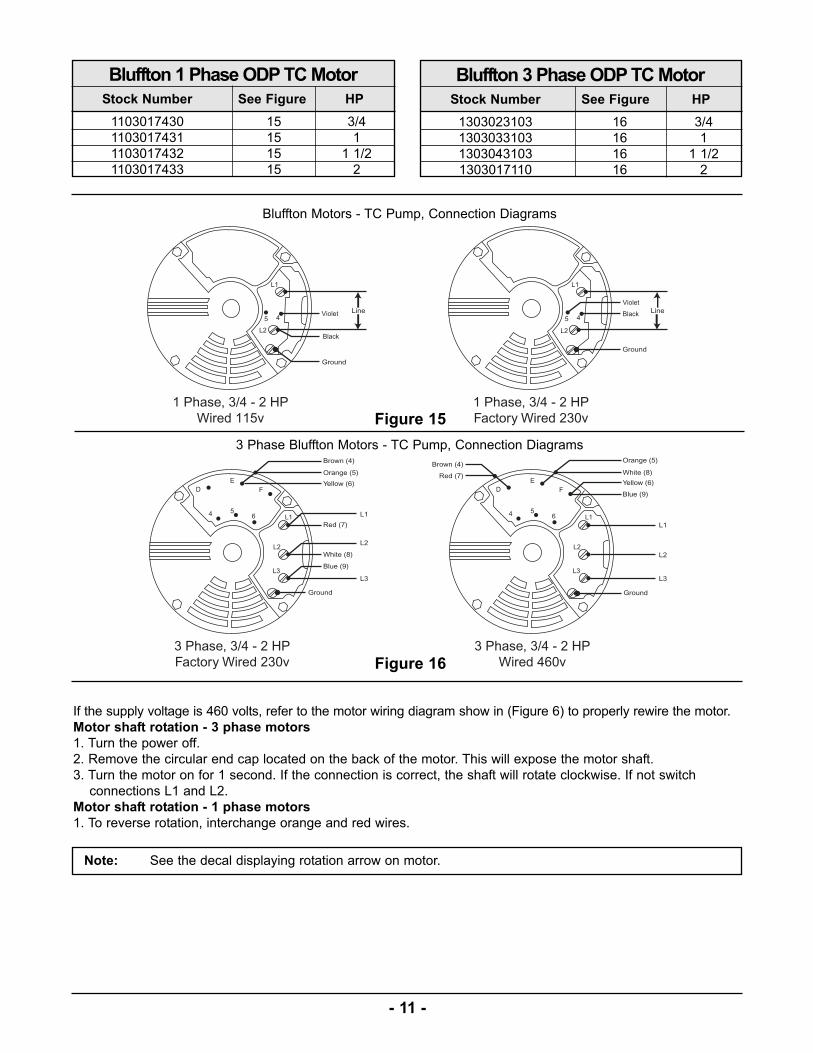
Note: See the decal displaying rotation arrow on motor.
3 Phase Bluffton Motors - TC Pump, Connection Diagrams
Black
Black
Figure 16
Figure 15
Bluffton Motors - TC Pump, Connection Diagrams
Bluffton 1 Phase ODP TC Motor
Stock Number See Figure HP
1103017430 15 3/4
1103017431 15 1
1103017432 15 1 1/2
1103017433 15 2
Bluffton 3 Phase ODP TC Motor
Stock Number See Figure HP
1303023103 16 3/4
1303033103 16 1
1303043103 16 1 1/2
1303017110 16 2
If the supply voltage is 460 volts, refer to the motor wiring diagram show in (Figure 6) to properly rewire the motor.
Motor shaft rotation - 3 phase motors
1. Turn the power off.
2. Remove the circular end cap located on the back of the motor. This will expose the motor shaft.
3. Turn the motor on for 1 second. If the connection is correct, the shaft will rotate clockwise. If not switch
connections L1 and L2.
Motor shaft rotation - 1 phase motors
1. To reverse rotation, interchange orange and red wires.

Baldor Motors - FC Pump, Connection Diagrams
Baldor Motors - FC Pump, Connection Diagrams
Figure 18
Figure 17
-12 -
Catalog Number See Figure HP
JML1406T 17 3
JML1409T 18 5*
JML1509T 18 7-1/2*
JML1511T 18 10*
Baldor 1 Phase ODP FC Motor
Catalog Number See Figure HP
JMM3116T 19 1
JMM3154T 19 1-1/2
JMM3157T 19 2
JMM3158T 19 3
JMM3212T 19 5
JMM3219T 19 7 1/2
JMM3312T 19 10
JMM3314T 19 15
Baldor 3 Phase ODP FC Motor
*Motor rated for 230v and cannot be connected to 115v.
FC Pump motors are factory wired for 230 volts. Motor is Nema JM frame. If the supply voltage for a 1 phasemotor is 115 volts refer to the wiring diagrams shown below to properly rewire the motor.
Note: For 1 phase motors, Baldor has a wiring diagram on the motor for standard rotation. Standard rotation is counter clockwise facing the end opposite the shaft extension.
However, the shaft must rotate clockwise for proper operation of the pump. Instructions are shown on thewiring diagram for opposite standard rotation (clockwise facing end opposite shaft extension).
Since the pump has been factory tested, the motor is wired correctly for 230 volts. If the voltage is 115volts, rewire the motor accordingly.
The information stated above also applies to the A.O. Smith Motors (Century) and U.S. Motors.
Electrical Connections - FC Pump

3 Phase Baldor Motors - FC Pump, Connection Diagrams
Figure 19
Catalog Number See Figure HP
P121 20 1
P123 21 1 1/2
P127 21 2
Century 1 Phase ODP FC Motor
Century Motors - FC Pump, Connection Diagrams
Figure 20
Century Motors - FC Pump, Connection Diagrams
Figure 21
- 13 -
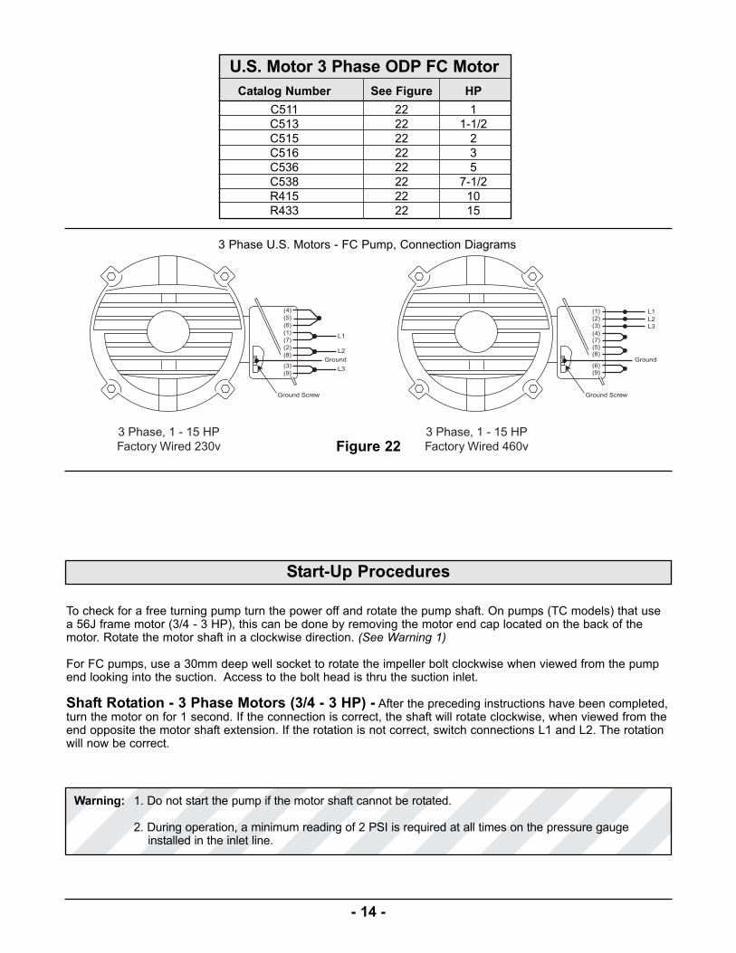
Figure 22
3 Phase U.S. Motors - FC Pump, Connection Diagrams
Catalog Number See Figure HP
C511 22 1
C513 22 1-1/2
C515 22 2
C516 22 3
C536 22 5
C538 22 7-1/2
R415 22 10
R433 22 15
U.S. Motor 3 Phase ODP FC Motor
- 14 -
To check for a free turning pump turn the power off and rotate the pump shaft. On pumps (TC models) that usea 56J frame motor (3/4 - 3 HP), this can be done by removing the motor end cap located on the back of themotor. Rotate the motor shaft in a clockwise direction. (See Warning 1)
For FC pumps, use a 30mm deep well socket to rotate the impeller bolt clockwise when viewed from the pumpend looking into the suction. Access to the bolt head is thru the suction inlet.
Shaft Rotation - 3 Phase Motors (3/4 - 3 HP) - After the preceding instructions have been completed,turn the motor on for 1 second. If the connection is correct, the shaft will rotate clockwise, when viewed from theend opposite the motor shaft extension. If the rotation is not correct, switch connections L1 and L2. The rotationwill now be correct.
Start-Up Procedures
Warning: 1. Do not start the pump if the motor shaft cannot be rotated.
2. During operation, a minimum reading of 2 PSI is required at all times on the pressure gaugeinstalled in the inlet line.

Valves - The suction inlet valve should be fully open and the discharge valve should be partially open. This willallow the pump to develop back pressure when it is started.
Priming - The pump must be primed before starting. The pump casing and suction piping must be filled withwater before starting the motor. On TC models, remove the vent plug in the top of the casing while pouring inpriming water. When water is poured into the pump to prime, remove all the air before starting the motor.
The pump will automatically fill with water when the pump is connected to a city main or hydrant. To relieve thetrapped air inside the pump, allow the water supply to run a minimum of 1 minute before starting the pump. Afterfilling the pump and inlet pipe with water, turn the motor on and off several times. Repeat this priming sequenceseveral times to be sure that all the air has been removed from the pump.
Once the preceding instructions have been completed, the pump can be started. The pump should be pumpingwater and rapidly build pressure. If not repeat the priming instructions. During operation, a minimum reading of 2PSI is required at all times on the pressure gauge installed in the inlet line.
Final Inspection - Once the proceeding instructions have been completed, the pump can be started. Duringthe first few hours of operation, inspect the pump, piping and auxiliary equipment, used in conjunction with thepump. Check for leaks, vibration or noises.
If a problem arises, consult a Webtrol representative or call Webtrol at (314) 631-9200 for assistance.
View facing end opposite shaft extension
- 15 -
Lubrication
On the TC SS Series Centrifugal, it is not necessary to lubricate the pump or motor. The motor is designed withsealed ball bearings.
The motors used on the FC SS Series Centrifugal pumps require periodic lubrication. Good results can beobtained if the following recommendations are used in your maintenance program.
A high grade ball or roller bearing grease should be used.

Lubrication Procedure
1. Stop motor
2. Clean grease fitting or remove outlet plug(See Photo)
3. Add the recommended amount of grease while motor is warm
4. Reinstall grease outlet plug
Name Manufacturer
SR1 (Factory Installed) ChevronRykon Premium #2 American Oil Co.
Shell Dolium R Shell Oil Co.
Recommended Greases
Severity Of Service Ambient Temperature Atmospheric Contamination Regreasing Interval
Standard 104 °F Clean, Little Corrosion 5500 Hours
Severe 130 °F Moderate Dirt, Corrosion 2750 Hours
Service Conditions
By Weight By Volume
Ounce Grams In3 Teaspoon
0.30 8.4 0.6 2
Amount Of Grease
Grease Fitting
Notes:
Outlet Plug
- 16 -
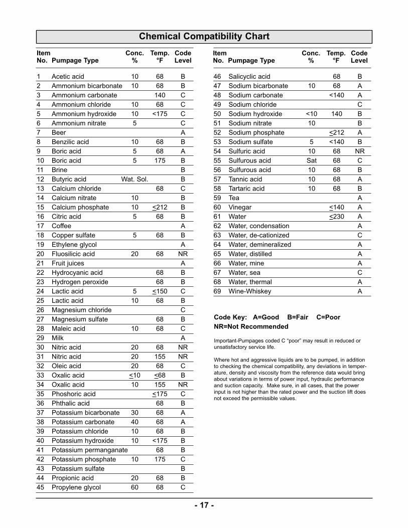
Chemical Compatibility Chart
1 Acetic acid 10 68 B
2 Ammonium bicarbonate 10 68 B
3 Ammonium carbonate 140 C
4 Ammonium chloride 10 68 C
5 Ammonium hydroxide 10 <175 C
6 Ammonium nitrate 5 C
7 Beer A
8 Benzilic acid 10 68 B
9 Boric acid 5 68 A
10 Boric acid 5 175 B
11 Brine B
12 Butyric acid Wat. Sol. B
13 Calcium chloride 68 C
14 Calcium nitrate 10 B
15 Calcium phosphate 10 <212 B
16 Citric acid 5 68 B
17 Coffee A
18 Copper sulfate 5 68 B
19 Ethylene glycol A
20 Fluosilicic acid 20 68 NR
21 Fruit juices A
22 Hydrocyanic acid 68 B
23 Hydrogen peroxide 68 B
24 Lactic acid 5 <150 C
25 Lactic acid 10 68 B
26 Magnesium chloride C
27 Magnesium sulfate 68 B
28 Maleic acid 10 68 C
29 Milk A
30 Nitric acid 20 68 NR
31 Nitric acid 20 155 NR
32 Oleic acid 20 68 C
33 Oxalic acid <10 <68 B
34 Oxalic acid 10 155 NR
35 Phoshoric acid <175 C
36 Phthalic acid 68 B
37 Potassium bicarbonate 30 68 A
38 Potassium carbonate 40 68 A
39 Potassium chloride 10 68 B
40 Potassium hydroxide 10 <175 B
41 Potassium permanganate 68 B
42 Potassium phosphate 10 175 C
43 Potassium sulfate B
44 Propionic acid 20 68 B
45 Propylene glycol 60 68 C
46 Salicyclic acid 68 B
47 Sodium bicarbonate 10 68 A
48 Sodium carbonate <140 A
49 Sodium chloride C
50 Sodium hydroxide <10 140 B
51 Sodium nitrate 10 B
52 Sodium phosphate <212 A
53 Sodium sulfate 5 <140 B
54 Sulfuric acid 10 68 NR
55 Sulfurous acid Sat 68 C
56 Sulfurous acid 10 68 B
57 Tannic acid 10 68 A
58 Tartaric acid 10 68 B
59 Tea A
60 Vinegar <140 A
61 Water <230 A
62 Water, condensation A
63 Water, de-cationized C
64 Water, demineralized A
65 Water, distilled A
66 Water, mine A
67 Water, sea C
68 Water, thermal A
69 Wine-Whiskey A
Item Conc. Temp. CodeNo. Pumpage Type % °F Level
Item Conc. Temp. CodeNo. Pumpage Type % °F Level
Code Key: A=Good B=Fair C=Poor
NR=Not Recommended
Important-Pumpages coded C “poor” may result in reduced or
unsatisfactory service life.
Where hot and aggressive liquids are to be pumped, in addition
to checking the chemical compatibility, any deviations in temper-
ature, density and viscosity from the reference data would bring
about variations in terms of power input, hydraulic performance
and suction capacity. Make sure, in all cases, that the power
input is not higher than the rated power and the suction lift does
not exceed the permissible values.
- 17 -

Motor Fails To Start Or Run At Full SpeedPossible Cause Of Trouble Corrective Action
Start capacitor failed - 1 phase motor (motor hums) Replace start capacitor
Power Loss Replace bad fuse or reset circuit breaker (check for correct fuse/breaker size)
Incorrect voltage - voltage must be within + 10% of motor rated voltage. 1. check incoming voltage, contact power company2. Verify that the voltage of the motor matches the power supply voltage
Example: Rated voltage 230 volts Range: 207 - 253 volts 3. Check wire size from main switch to motor.
Defective wire or connections Replace defective wires, tighten and clean connections.
Grounded motor Have motor rewound with new winding or replace motor.
Excessive Noise While Pump Is OperatingPossible Cause Of Trouble Corrective Action
Cavitation (noise like gravel in pump) 1. Increase size of inlet line2. Reduce flow rate - GPM3. Too viscous (liquid is too thick) maximum viscosity is 80 centipoise (CPS)
Pump not secured to firm foundation Bolt down to secure and rigid base
Noisy motor 1. Ensure that motor fan is clear2. Remove motor from pump. If noise persists check for smooth bearing
operation. Replace bad bearings/or motor
Pump LeaksPossible Cause Of Trouble Corrective Action
Worn mechanical seal due to abrasive liquid/corrosion 1. Replace seal with materials compatible with liquid pumped.2. Install filter on inlet line.
Lack of water - carbon seal on mechanical seal face overheats and 1. Replace sealwears rapidly 2. Verify inlet pressure, minimum pressure on inlet gauge is 2 PSIG
Inlet pressure to high Reduce inlet pressure
Misalignment Check for a bent motor shaft
Worn “O” ring seal Replace O-ring seal
Teflon gasket leaks “bowed” For FC Series only. Tighten bolt shown In exploded view sheet to 11 Ft. Lbs.
Pump Operates, But Delivers Little Or No WaterPossible Cause Of Trouble Corrective Action
Incorrect rotation on 3 phase motor Interchange any two incoming power leads to the motor.
Low line voltage (See motor trouble shooting section above)
Air Locked Pump Fill pump & inlet pipe with water - jog motor on and off several times. Refillwith water. Repeat procedure several times to remove all air
Worn or plugged impeller 1. Replace impeller2. Clean clogged impeller, install filter on Inlet
Inadequate inlet pressure Minimum pressure on the inlet side of pump is 2 PSIG
Diameter of suction/discharge pipe is to small 1. Size of inlet pipe should be at least equal to the threaded inlet size in thepipe inlet housing
2. Calculate friction losses for the discharge pipe. Replace undersized piping.For assistance call Webtrol (314) 631-9200
Broken Shaft If motor shaft is broken replace motor
- 18 -
Thank You For Purchasing A Stainless Steel Centrifugal Pump
We at Webtrol are constantly working on new products to make your job easier, while making your systems more
efficient, reliable and affordable.
Your opinion means a lot to us, so please let us know what you think about our Stainless Steel Centrifugal Pump.
Weber Industries, Inc. / Manufacturers of Webtrol Products8417 New Hampshire Ave. / St. Louis, MO 63123
Phone: (314) 631-9200 Fax: (314) 631-3738 E-mail: [email protected]