installation- and maintenance instruction · pdf file · 2016-05-04installation-...
TRANSCRIPT

Providing sustainable energy solutions worldwide
178 028 35-7 2015-09–15
Installation- and maintenance instruction
BF1


3 Bentone BF1
General
Table of contents
GENERALImportant to think about! _____________________________________________4Safety instructions ______________________________________________________4Warnings ___________________________________________________________________4Electrical safety __________________________________________________________5Assembly and Service _________________________________________________5Condensation in the flue ______________________________________________5Measures to increase the temperature __________________________5Adjusting the burner ___________________________________________________5
1. TECHNICAL DATA _______________________________________________________61.1 Dimensions BF1 _______________________________________________________6
1.1.1 Dimensions, flanges _______________________________________61.2 Model BF1 FU 63-16 ________________________________________________7
1.2.1 Burner output/ Basic settings _________________________71.3 Model BF1 KA 76-22 ________________________________________________8
1.3.1 Burner output/ Basic settings _________________________81.4 Model BF1 KS 76-24 ________________________________________________9
1.4.1 Burner output/ Basic settings _________________________91.5 Model BF1 PL 6-7-21,5-10 (E) _________________________________10
1.5.1 Burner output/ Basic settings _______________________101.6 Recommended nozzles and pressures _____________________111.7 Nozzle table, 8-15 bar ____________________________________________11
1.7.1 Burner with preheater __________________________________111.8 Description ____________________________________________________________12
1.8.1 Components _______________________________________________13
2. INSTALLATION __________________________________________________________142.1 Delivery checks ______________________________________________________142.2 Preparations for installation _____________________________________142.3 Oil supply ______________________________________________________________142.4 Electrical connection _______________________________________________142.5 Choice of nozzle ____________________________________________________142.6 Brake plate and airflow setting _________________________________142.7 Burner installation ___________________________________________________15
2.7.1 Hole pattern ________________________________________________152.7.2 Burner installation ________________________________________152.7.3 Oil pipes _____________________________________________________152.7.4 Electrical connection ____________________________________15
3. BASIC SETTINGS ______________________________________________________163.1 Example of basic setting _________________________________________16
3.1.1 Choice of nozzle __________________________________________163.1.2 Basic setting _______________________________________________163.1.3 Nozzle assembly adjustment ________________________173.1.4 Air intake adjustment ___________________________________173.1.5 Method of adjusting air quantity ____________________173.1.6 Inlet cone, air adjustment _____________________________173.1.7 Air intake rotation ________________________________________183.1.8 Air duct ______________________________________________________18
4. BURNER SERVICING ________________________________________________194.1 Warning ________________________________________________________________19
4.1.1 Service position ___________________________________________194.1.1.1 Service position 1 ______________________________________194.1.1.2 Service position 2 ______________________________________194.1.1.3 Service position 3 ______________________________________20
4.1.2 Combustion assembly service ______________________204.1.3 Preheater replacement _________________________________214.1.4 Oil pump replacement __________________________________214.1.5 Fan motor replacement ________________________________224.1.6 Air intake and intake cone service _________________234.1.7 Fan wheel checks ________________________________________23
4.1.7.1 Inspection ______________________________________________234.1.7.2 Cleaning, alternative 1 __________________________________244.1.7.3 Cleaning, alternative 2 __________________________________25
4.1.8 Electrical module _________________________________________254.1.8.1 Replacement of complete electrical package __________264.1.8.2 Replacement of individual electrical components ______26
5. PUMP INSTRUCTIONS ______________________________________________275.1 Suntec AS47CK _____________________________________________________27
5.1.1 Technical data ____________________________________________275.1.2 Components _______________________________________________275.1.3 Filter replacement ________________________________________275.1.4 One-pipe system _________________________________________275.1.5 Function AS47CK ________________________________________285.1.6 Suction pipe tables AS47CK ________________________29
5.1.6.1 Overhead Tank _________________________________________295.1.6.2 Underlying Tank ________________________________________29
5.2 Danfoss BFP 11 and BFP 21 ___________________________________305.2.1 Technical data _____________________________________________305.2.2 Components _______________________________________________305.2.3 Filter replacement BFP 11 ____________________________30
5.2.3.1 One-pipe system _______________________________________30
5.2.4 Filter replacement BFP 21 ____________________________305.2.4.1 One-pipe system _______________________________________30
5.2.5 Function BFP 11 and BFP 21 _______________________315.2.6 LE-S System ______________________________________________325.2.7 Purging ______________________________________________________325.2.8 Suction pipe tables BFP11 and BFP21 __________33
5.2.8.1 Overhead Tank _________________________________________335.2.8.2 Underlying Tank ________________________________________33
6. PREHEATER ______________________________________________________________346.2.1 Function FPHE 5 _________________________________________346.2.2 Function FPHE 5-LE ____________________________________34
6.2.2.1 LE-valve ________________________________________________34
7. ELECTRICAL EQUIPMENT
LMO1..2..4../LOA2..4.. _____________________________________________357.1 Wiring diagram ______________________________________________________35
7.1.1 Component list____________________________________________367.1.2 Function LMO1..2..4../LOA2..4.. ___________________367.1.3 Technical data _____________________________________________37
ELECTRIC EQUIPMENT ____________________________________________387.2 Colour codes LMO14/24 ________________________________________387.3 Fault codes LMO14/24 ___________________________________________38
8. FAULT LOCATION ______________________________________________________398.1 Burner will not start ________________________________________________398.2 Burner will not start after normal use ________________________398.3 Delayed ignition, burner starts; pulsation ___________________39
9. DECLARATION OF CONFORMITY _____________________________40
10. OIL BURNERS MAINTENANCE INSTRUCTIONS ________41

4 Bentone BF1
General
Varning!
Important to think about!Read this manual
• This manual should be followed by anyone who for any reason performs
work on the installation or its component parts.
• The manual is especially intended for authorized personnel.
• The manual is to be considered as part of the burner and must always
be kept in the vicinity of the installation site.
• Enertech recommends that the burner be shut down when the oil tank is filled, and for six hours thereafter, to reduce the risk of blockages.
Safety instructionsThe electrical installation must be carried out according to the high voltage provisions and be performed in a professional manner, so that the risk of oil leakage, fire or personal injury is avoided
Warnings• The manual must be read before installation and start-up.
• This manual should be followed by anyone who for any reason performs work on the installation or its component parts.
• The manual is to be considered as part of the burner and must always be kept in the vicinity of the installation site.
• Ensure that the fresh air inlet to the room where the burner is located is always open.
• The burner may only be installed by authorized personnel.
• Check that the burner is suitable for the boiler type.
• The burner must be installed in accordance with local legislation regarding electrical safety and fuel supply.
• The burner is designed for oil viscosities ranged between 1.2 and 8.0 cSt at 20°C.
• The burner must be protected by at most a 10 A fast-blow or 6.3 A slow-blow fuse.
• No burner safety system may be disconnected.
• The installation engineer must ensure that the boiler room is supplied with sufficient fresh air in accordance with local standards.
• Cut the power and shut-off the fuel supply before performing service.
• Enertech recommends that the burner be shut down when the oil tank is filled, and for six hours thereafter, to reduce the risk of blockages.
• The external temperature of the burner’s component parts may exceed 60°C.
• Ensure that the burner is protected from water spills, as its design will not withstand such.
• Oil filters should be used.
• Only use spare parts recommended by Enertech.
5 Bentone BF1
General
Electrical safety• If any electrical connections are made other than those recommended
by Enertech, there is a risk of personal injury and equipment damage.
• The electrical installation must be carried out according to the high voltage provisions and be performed in a professional manner, so that the risk of oil leakage, fire or personal injury is avoided.
• The installation engineer must be especially careful to ensure that no electrical wiring or oil lines are pinched or damaged during installation or service
Assembly and Service• If the boiler is equipped with an inspection hatch, the hatch should be
fitted with an interlock.
• Filters must be fitted to the oil supply line.
• Shut-off cocks must be fitted to the oil supply line.
• Oil lines must adhere to the current national standards of each respective country.
Condensation in the flueA modern burner works with lower surplus air and also often with smaller nozzles than older types. This raises efficiency but also increases the risk of condensation in the flue. The risk increases if the cross section of the flue channel is too great. Flue gas temperatures should be above 60°C measured 0.5 m from the flue chimney.
If the burner is used together with a condensing boiler, working condensing, the installation must have a chimney that manages this type of operating conditions.
Measures to increase the temperature• Insulate the flue in cold loft space.
• Install an insert flue.
• Install a Dragex draught stabilizer or equivalent (which dries and entilates the flue during shutdown periods).
Adjusting the burnerIn order to achieve correct adjustment flue gas analysis and temperature measurements must be carried out. Otherwise there is a risk of soot build-up, poor efficiency or condensate precipitation in the flue..

6 Bentone BF1
General
Flange 1 Flange 2
Flange 3 Flange 4
12
ø89,5
136–150
12
10,3
25
130–150
ø89,7
125
ø90 4
10
125–150
ø90 510
,3
ø89
172
B
190
226
278
145
1. TECHNICAL DATA1.1 Dimensions BF1
1.1.1 Dimensions, flanges

7 Bentone BF1
General
ø63
ø67
ø16
7,0–8,0
1,6–2,0 (-0,1)+0,5
-0,5
0,0
0,5
1,0
1,5
2,0
2,5
3,0
3,5
4,0
10 15 20 25 30 35 40 45 50 55 60
Burner output, kW
Boi
ler
over
pres
sure
, mba
r
0,0
2,0
4,06,0
8,0
10,0
12,0
14,0
16,018,0
20,0
22,0
15 20 25 30 35 40 45 50 55
Burner output, kW
Sca
le
Air settin
gs
Nozzle assembly
! Scale value applies to 0 mbar furnace pressure.
1.2 Model BF1 FU 63-16
Length of blast tube
Protrusion from flange, measurement B
Flange
1 2 3 4
103 68 81 89 88
133 98 111 119 118
183 148 161 169 168
1.2.1 Burner output/ Basic settings 1,3 - 4,6 kg/h 15 - 55 kW

8 Bentone BF1
General
ø76
ø78
ø22
8,0-9,0
2,7-3,3 0,5-1,5
-0,5
0,0
0,5
1,0
1,5
2,0
2,5
3,0
3,5
4,0
20 25 30 35 40 45 50 55 60 65 70 75 80
Burner output, kW
Boi
ler
over
pres
sure
, mba
r
! Scale value applies to 0 mbar furnace pressure.
1.3 Model BF1 KA 76-22
Length of blast tube
Protrusion from flange, measurement B
Flange
1 2 3 4
117 82 95 103 102
147 112 125 133 132
224 189 202 210 209
1.3.1 Burner output/ Basic settings 2,1 - 6,3 kg/h
25 - 75 kW

9 Bentone BF1
General
! Scale value applies to 0 mbar furnace pressure.
ø73
ø24
ø76
10,0-11,0
2,3-3,1 0,5-1,5
Burner output, kW
Boi
ler
over
pres
sure
, mba
r
-0,5
0,0
0,5
1,0
1,5
2,0
2,5
3,0
3,5
4,0
30 35 40 45 50 55 60 65 70 75 80 85 90 95
0,0
2,0
4,0
6,0
8,0
10,0
12,0
14,0
16,0
18,0
20,0
22,0
35 40 45 50 55 60 65 70 75 80 85 90
Burner output, kW
Sca
le
Air settings
Nozzle
assem
bly
1.4 Model BF1 KS 76-24
Length of blast tube
Protrusion from flange, measurement B
Flange
1 2 3 4
117 82 95 103 102
147 112 125 133 132
224 189 202 210 209
1.4.1 Burner output/ Basic settings 3,0 - 7,6 kg/h 35 - 90 kW

10 Bentone BF1
General
! Scale value applies to 0 mbar furnace pressure.
ø89
ø21,5
10,0-11,0
2,3-3,1 0,5-1,5
-0,5
0,0
0,5
1,0
1,5
2,0
2,5
3,0
3,5
4,0
10 15 20 25 30 35 40 45 50
Burner output, kW
Boi
ler
over
pres
sure
, mba
r
0,0
2,0
4,0
6,0
8,0
10,012,0
14,0
16,0
18,0
20,0
22,0
15 20 25 30 35 40 45
Burner output, kW
Sca
le
Air settin
gs
1.5 Model BF1 PL 6-7-21,5-10 (E)
Length of blast tube
Protrusion from flange, measurement B
Flange
1 2 3 4
78 43 56 64 63
127 92 105 113 112
157 122 135 143 142
1.5.1 Burner output/ Basic settings 1,3 - 3,8 kg/h 15 - 45 kW

11 Bentone BF1
General
1.6 Recommended nozzles and pressuresBecause of the different types of boiler in existence, with varying furnace geometries and furnace loads, it is not possible to commit to any given spray angle or spay pattern. Note that spray angles and spray patterns change with pump pressures.
Nozzle 60° Solid/Hollow cone
80° Solid/Hollow conel
Pump pressure 10 bar (8–14 bar) Fuel oil 1
10 bar (7–12 bar) Kerosene
1.7 Nozzle table, 8-15 barPump pressure, bar
Gph 8 9 10 11 12 13 14 15
kg/h kW kg/h kW kg/h kW kg/h kW kg/h kW kg/h kW kg/h kW kg/h kW
0,40 1,33 16 1,41 17 1,49 18 1,56 18 1,63 19 1,70 20 1,76 21 1,82 21
0,50 1,66 20 1,76 21 1,86 22 1,95 23 2,04 24 2,12 25 2,20 26 2,28 27
0,60 2,00 24 2,12 25 2,23 26 2,34 28 2,45 29 2,55 30 2,64 31 2,73 32
0,65 2,16 26 2,29 27 2,42 29 2,54 30 2,65 31 2,75 33 2,86 34 2,96 35
0,75 2,49 29 2,65 31 2,79 33 2,93 35 3,08 36 3,18 38 3,30 39 3,42 40
0,85 2,83 33 3,00 36 3,16 37 3,32 39 3,47 41 3,61 43 3,74 44 3,87 46
1,00 3,33 39 3,53 42 3,72 44 3,90 46 4,08 48 4,24 50 4,40 52 4,56 54
1,10 3,66 43 3,88 46 4,09 48 4,29 51 4,48 53 4,67 55 4,84 57 5,01 59
1,20 3,99 47 4,24 50 4,47 53 4,68 55 4,89 58 5,09 60 5,29 63 5,47 65
1,25 4,16 49 4,40 52 4,65 55 4,88 58 5,10 60 5,30 63 5,51 65 5,70 68
1,35 4,49 53 4,76 56 5,02 59 5,27 62 5,50 65 5,73 68 5,95 70 6,15 73
1,50 4,98 59 5,29 63 5,58 66 5,85 69 6,11 72 6,36 75 6,60 78 6,83 81
1,65 5,49 65 5,82 69 6,14 73 6,44 76 6,73 80 7,00 83 7,27 86 7,52 89
1,75 5,82 69 6,18 73 6,51 77 6,83 81 7,14 85 7,42 88 7,71 91 7,97 94
2,00 6,65 79 7,06 84 7,45 88 7,81 93 8,18 97 8,49 101 8,81 104 9,12 108
2,25 7,49 89 7,94 94 8,38 99 8,78 104 9,18 109 9,55 113 9,91 117 10,26 122
The table applies to oils with a viscosity of 4.4 mm2/s (cSt) at a density of 830 kg/m3.
1.7.1 Burner with preheaterAllow for a reduction in oil quantity of 5–20% with preheating owing to:
• Temperature increases at the nozzle.
• Nozzle design.
• Capacity (the higher the capacity the lower the difference).

12 Bentone BF1
General
2 3 4
7
1
10
5
6
89
17
7
6
5 3
18
20
19
23 2124 22
16
1.8 Description
13 Bentone BF1
General
15
14
13 5
2 11 121
10
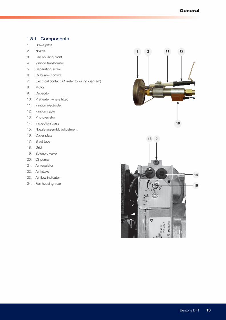
1.8.1 Components1. Brake plate
2. Nozzle
3. Fan housing, front
4. Ignition transformer
5. Separating screw
6. Oil burner control
7. Electrical contact X1 (refer to wiring diagram)
8. Motor
9. Capacitor
10. Preheater, where fitted
11. Ignition electrode
12. Ignition cable
13. Photoresistor
14. Inspection glass
15. Nozzle assembly adjustment
16. Cover plate
17. Blast tube
18. Grid
19. Solenoid valve
20. Oil pump
21. Air regulator
22. Air intake
23. Air flow indicator
24. Fan housing, rear

14 Bentone BF1
General
2. INSTALLATION2.1 Delivery checksCheck that everything has been delivered and that the goods are not transport damaged. Any delivery faults must be reported to the supplier. Transport damage must be reported to the forwarder.
2.2 Preparations for installationCheck that the burner’s measurements and capacity range is suitable for the boiler in question. The power information on the data plate refers to the burner’s max. and min. power.
2.3 Oil supplyIn order to achieve good operational reliability it is important that the oil supply system is laid out correctly.
Observe the following:• Choice of pipe diameters, pipe lengths and height differences (refer to
pump instructions).
• Piping should be run with a minimum of joints/compression fittings.
• Pipework must be laid out so that oil hoses are not subjected to tension or overbending when the burner is swung out or removed for service.
• The oil filter should be installed so that the filter cartridge can easily be replaced
2.4 Electrical connectionBefore electrical installation is begun, electricity must be switched off at the main switch. If the boiler has a 7-pole or a 4-pole Eurostecker (only on 2-stage burners), these often fit directly to the burner. Otherwise use the connectors supplied. The operating thermostat, the max. thermostat and the inspection hatch (where fitted) interlock can then be wired in series on the incoming phase connected to L1 or connected between T1 and T2. In the first mentioned case a jumper is installed between T1 and T2.(Refer to connection in the section Electrical equipment).
2.5 Choice of nozzle(Technical data): Recommended nozzle and nozzle table.
2.6 Brake plate and airflow settingBefore operations basic burner setting may be made according to the diagram. (Refer to basic settings). Note that this only refers to the basic setting; the setting must be adjusted after the burner has been started. At this time flue gas analysis and soot measurement must be carried out.
! If any electrical connection is used other than that recommended by Enertech, there may be a risk of equipment damage and personal injury.

15 Bentone BF1
General
Return Inlet
E
E
X1
X2
2.7 Burner installation2.7.1 Hole patternCheck that the hole pattern matches the flange supplied. (Refer to Technical data.)
2.7.2 Burner installation1. Install the flange and the gasket on the boiler.
2. Attach the front piece to the flange.
3. Insulate between the burner register and the boiler cover for reduced heat radiation.
4. Install the selected nozzle. (Refer to Technical data.)
5. Install the brake plate and check the ignition electrodes (refer to Burner service.).
6. Install the burner body to the front piece and lock with screw (E).
2.7.3 Oil pipes1. Check the oil pipe dimensions. (Refer to Pump Instructions.)
2. The oil filter should be installed in the oil supply line. If an air separator is fitted, the oil filter should be installed before the air filter to increase the life span of the filter.
3. For one-pipe systems the return plug must be removed. (Refer to Pump Instructions.)
4. When installing oil hoses, check that the supply and return hoses are connected to the correct connections on the oil pump. The hoses must be run so that they are not bent or tensioned.
5. Purge the oil system. The oil pump will be damaged if it is run dry.
6. The vacuum should not be lower than 0.3 bar depression in the suction line at start up.
2.7.4 Electrical connectionIf the boiler lacks ready-connected plugs, connect using the supplied plug, X2 in accordance with the wiring diagram.
1. Disconnect the power at the main switch.
2. Wire the Eurostecker X2 as in alt. 1–3 (refer to Electrical equipment).
3. Connect the Eurostecker X2 to the burner.
4. Switch on the power at the main switch.

16 Bentone BF1
General
3. BASIC SETTINGS3.1 Example of basic setting3.1.1 Choice of nozzleBF1 FU 63-16
Burner output 30 kW
Estimated nozzle output: 30 / 11,86* = 2,53 kg/h
Choice of nozzle according to table. (Refer to Technical data.) According to the nozzle table, the following nozzle is indicated:
Nozzle: 0,65 Gph
Pump pressure: 11,0 bar
BF1 FU 63-16/FUV 63-16
Burner output 30 kW
Because of preheater, output is adjusted upward for choice of nozzle according to table. (Refer to Technical data 2.6).)
Estimated nozzle output: 30 x 1,06 = 31,8 kW
31,8 / 11,86* = 2,68 kg/h
Choice of nozzle according to table. (Refer to Technical data). According to the nozzle table, the following nozzle is indicate
Nozzle: 0,75 Gph
Pump pressure: 9,5 bar
* Calorfic value Light oil = 11,86 kWh/kg
3.1.2 Basic settingSetting values for 30 kW according to basic settings tables. (Refer to Technical data FU 63-16).
Air setting = 11,0
Insert setting = 4,0

17 Bentone BF1
General
Ι
Π
M
3.1.3 Nozzle assembly adjustmentThe burner is fitted with a regulator which changes the brake plate position in the blast tube. This is used to set the correct pressure drop across the combustion assembly and thereby achieve good combustion without pulsation.
The setting to be chosen is dependent among other things on set output and furnace pressure.
Brake plate setting
• Less diffusion: turn screw to left.
• More diffusion: turn to right.
Setting brake plate position affects air flow. It is therefore always necessary to adjust the air with the burner air regulator afterwards.
3.1.4 Air intake adjustmentAir settings are very important for achieving good combustion with neither too much, nor too little, air. Adjustment of combustion airflow is carried out by turning the air regulator with an Allen key. How far open the air regulator must be is determined by output, furnace pressure and other burner settings such as blast tube position.
3.1.5 Method of adjusting air quantitySetting the air regulator is dependent on how the screw (with which air regulation is adjusted) is installed. If the air intake is installed underneath as shown in illustration Ι, turning the screw clockwise will reduce airflow, and anticlockwise increase it. If the air intake is installed on top as shown in illustration Π, clockwise adjustment increases airflow, and anticlockwise reduces it.
3.1.6 Inlet cone, air adjustmentAirflow is also affected by the position of the inlet cone. However, it is extremely rare that this needs to be adjusted; it should be left in the standard STD position to achieve good starts and operations. (A cast-in arrow on the fan housing indicates the position of the inlet cone. In addition to the scale on the inlet cone casting, there is also a mark (M) indicating the factory setting.)
18 Bentone BF1
General
D
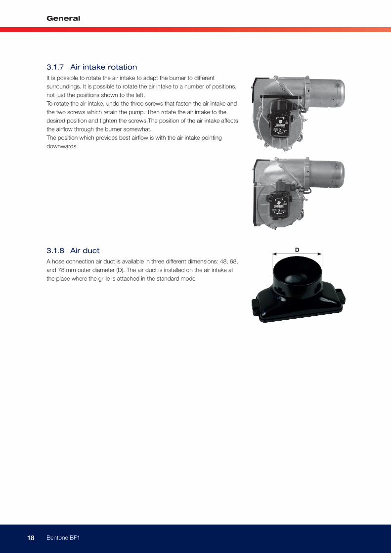
3.1.7 Air intake rotationIt is possible to rotate the air intake to adapt the burner to different surroundings. It is possible to rotate the air intake to a number of positions, not just the positions shown to the left. To rotate the air intake, undo the three screws that fasten the air intake and the two screws which retain the pump. Then rotate the air intake to the desired position and tighten the screws.The position of the air intake affects the airflow through the burner somewhat. The position which provides best airflow is with the air intake pointing downwards.
3.1.8 Air ductA hose connection air duct is available in three different dimensions: 48, 68, and 78 mm outer diameter (D). The air duct is installed on the air intake at the place where the grille is attached in the standard model

19 Bentone BF1
General
!Warning
! When servicing or replacing components that affect combustion, analyses and soot tests must be carried out on the installation.
4. BURNER SERVICING4.1 WarningService must be carried out after 3,000 operating hours, or at least once per year. Only authorized personnel may perform service. Before any type of service work is begun, switch of the power at the main switch and shut off the oil. Exercise caution as parts which are exposed when the burner is taken apart can be hotter than 60°C. The installation engineer must be especially careful to ensure that no electrical wiring or oil lines are pinched or damaged during installation or service.
4.1.1 Service position
4.1.1.1 Service position 1
1. Switch off the power at the main switch and disconnect the Eurostecker from the burner.
2. Undo the screw which fastens the burner front piece to the fan housing, but only so much as to allow the fan housing to be removed from the burner front piece.
3. Remove the fan housing from the burner front piece and pull it backwards until the combustion assembly is free of the burner front piece.
4. Suspend the fan housing by the fan housing attachment point (for joining the front piece to the fan housing) on the screw (for joining the front piece to the fan housing) as illustrated to the left. If necessary, tighten the screw somewhat to ensure that the burner is suspended safely.något för att få brännaren att hänga säkrare.
4.1.1.2 Service position 2
1. Switch off the power at the main switch and disconnect the Eurostecker from the burner.
2. Undo the screw which fastens the burner front piece to the fan housing, but only so much as to allow the fan housing to be removed from the burner front piece.
3. Remove the fan housing from the burner front piece and pull it backwards until the combustion assembly is free of the burner front piece.
4. Turn the screw into the front piece until there is a gap of approx. 5 mm between the metal and the screw head.
5. Suspend the fan housing by the fan housing service attachment on the screw used for joining the front piece to the fan housing, with the motor upwards, as shown in the illustration to the left.

20 Bentone BF1
General
! When servicing or replacing components that affect combustion, analyses and soot tests must be carried out on the installation.
4.1.1.3 Service position 3
1. Switch off the power at the main switch and disconnect the Eurostecker from the burner.
2. Undo the screw which fastens the burner front piece to the fan housing, but only so much as to allow the fan housing to be removed from the burner front piece.
3. Remove the fan housing from the burner front piece and pull it backwards until the combustion assembly is free of the burner front piece.
4. Turn the screw into the front piece until there is a gap of approx. 5 mm between the metal and the screw head.
5. Suspend the fan housing by the fan housing service attachment on the screw used for joining the front piece to the fan housing, with the air intake upwards, as shown in the illustration to the left.
4.1.2 Combustion assembly service1. Switch off the power at the main switch and disconnect the Eurostecker
from the burner.
2. If so desired, service position 1 may be used.
3. Carry out a visual inspection of the combustion assembly and check the various parts for defects.
4. Undo and remove the brake plate and the electrode package from the oil pipe. Clean the brake plate as necessary.
5. Screw off the nozzle.
6. Install the nozzle. The nozzle may not be cleaned; it must be replaced with a new nozzle if the existing one is considered defective.
7. Check the ignition electrodes. Replace as necessary (refer to Technical data for electrode settings).
8. Install the brake plate and electrode package. Check that the distance between the nozzle and brake plate is correct (refer to Technical data).
9. Undo the screw that the fan housing is suspended from. Reassemble the front piece and the fan housing and fasten them together.
10. Connect the Eurostecker and switch on the power at the main switch.
11. Start the burner and check the combustion.

21 Bentone BF1
General
F
G
! When servicing or replacing components that affect combustion, analyses and soot tests must be carried out on the installation.
4.1.3 Preheater replacement1. Switch off the power at the main switch and disconnect the Eurostecker
from the burner.
2. If so desired, service position 1 may be used.
3. Remove the brake plate and electrode package.
4. Disconnect the preheater cable from the preheater.
5. Screw off the nozzle.
6. Undo the nut that connects the oil pipe to the preheater.
7. Install the new preheater. Check the condition of the O-ring; replace as necessary.
8. Connect the preheater cable.
9. Install the nozzle.
10. Install the brake plate and electrode package. Check that the distance between the nozzle and brake plate is correct (refer to Technical data).
11. Re-assemble the burner.
12. Connect the Eurostecker and switch on the power at the main switch.
13. Start the burner and check the combustion.
4.1.4 Oil pump replacement1. Switch off the power at the main switch and disconnect the Eurostecker
2. Disconnect the oil hoses from the oil pump.
3. If so desired, service position 3 may be used.
4. Remove the solenoid cable from the pump.
5. Remove the connecting pipe (G) from the pump.
6. Undo the screws (F) and pull out the oil pump.
7. Install the oil pump in the burner. Tighten the screws and attach the connecting pipe (G). (It is important that the splines engage the pump coupling correctly.)
8. Connect the oil hoses. (For conversions from one- and two-pipe systems refer to the Pump instructions.)
9. Connect the Eurostecker and switch on the power at the main switch.
10. Start the burner, purge the pump, adjust to correct pressure and check combustion

22 Bentone BF1
General
H
! When servicing or replacing components that affect combustion, analyses and soot tests must be carried out on the installation.
4.1.5 Fan motor replacement1. Switch off the power at the main switch and disconnect the Eurostecker
from the burner.
2. If so desired, service position 2 may be used.
3. Remove the electrical connection from the motor.
4. Remove the electrical box retaining screw.
5. Remove the cable conduit entry to the ignition electrodes and the preheater (where fitted) and remove the photocell cable from the motor flange.
6. Undo the screws (H) to the motor flange, 5 pcs.
7. Lift away the motor.
8. Remove the drive coupling end from the motor shaft, loosen and remove the fan wheel.
9. Install the fan wheel on the new motor, tighten the locking screw. The fan wheel must be installed in the bottom position toward the motor shaft. Install the drive coupling end.
10. Align and fit the motor flange to the fan housing. Pay attention to the drive coupling so that it does not fall out, and also that it aligns correctly in the drive coupling end of the motor and pump.
11. Bolt the motor flange and fan housing together. Tighten the screws diagonally, and do not tighten hard one at a time. This is in order to ensure the fan housing and the motor flange assume the correct relative positions.
12. Place the cable conduit entry and the photocell cable in position.
13. Screw the electrical console in place.
14. Connect the motor wiring.
15. Join together the fan housing and the burner front piece.
16. Connect the Eurostecker and switch on the power at the main switch.
17. Start the burner and check the combustion.

23 Bentone BF1
General
I
! When servicing or replacing components that affect combustion, analyses and soot tests must be carried out on the installation.
4.1.6 Air intake and intake cone service1. Switch off the power at the main switch and disconnect the Eurostecker
from the burner.
2. If so desired, service position 3 may be used.
3. Remove the solenoid cable from the pump.
4. Remove the connecting pipe from the pump.
5. Undo the air intake retaining screws (I).
6. Remove the air intake.
7. Undo the inlet cone retaining screw; make note of the inlet cone position.
8. Remove the inlet cone from the fan housing.
9. Check the function and visual condition of the various air regulator components. Clean and replace components as necessary.
10. Re-assemble the burner. Be especially careful when installing the inlet cone; install it in the same position it had at removal.
11. Fit the O-ring in the groove between the fan housing and inlet cone. Ensure that it is properly located in the groove and is not damaged when the air intake is fitted.
12. Connect the Eurostecker and switch on the power at the main switch.
13. Start the burner and check the combustion.
4.1.7 Fan wheel checks
4.1.7.1 Inspection
1. Switch off the power at the main switch and disconnect the Eurostecker from the burner.
2. If so desired, service position 1 may be used.
3. Perform a visual inspection of the fan wheel. Spin the fan wheel with your finger, or carefully using a tool.
4. If the fan wheel is not very dirty, clean it carefully where possible.
5. If thorough cleaning is required, refer to point 5.1.7.2 or alternatively 5.1.7.3.
6. If cleaning is not necessary, re-assemble the burner.
7. Connect the Eurostecker and switch on the power at the main switch.
8. Start the burner and check the combustion.

24 Bentone BF1
General
I
! When servicing or replacing components that affect combustion, analyses and soot tests must be carried out on the installation.
4.1.7.2 Cleaning, alternative 1
1. Switch off the power at the main switch and disconnect the Eurostecker from the burner.
2. If so desired, service position 3 may be used.
3. Remove the solenoid cable from the pump.
4. Remove the connector pipe from the pump.
5. Undo the air intake retaining screws (I).
6. Remove the air intake.
7. Undo the inlet cone retaining screw; make note of the inlet cone position.
8. Remove the inlet cone from the fan housing.
9. Clean the fan wheel. Undo and if necessary remove the fan wheel for more thorough cleaning of the fan and fan housing.
10. Install the fan wheel; tighten the retaining screw. The fan wheel must be installed in the bottom position toward the motor shaft. Install the drive coupling end.
11. Re-assemble the burner. Pay attention to the drive coupling so that it does not fall out, and also that it aligns correctly in the drive coupling end of the motor and pump.
12. Fit the inlet cone in the same position as before disassembly
13. Fit the O-ring in the groove between the fan housing and inlet cone. Ensure that it is properly located in the groove and is not damaged when the air intake is fitted.
14. Connect the Eurostecker and switch on the power at the main switch.
15. Start the burner and check the combustion.

25 Bentone BF1
General
!Warning
H
! When servicing or replacing components that affect combustion, analyses and soot tests must be carried out on the installation.
4.1.7.3 Cleaning, alternative 2
1. Switch off the power at the main switch and disconnect the Eurostecker from the burner.
2. If so desired, service position 2 may be used.
3. Remove the electrical connection from the motor.
4. Remove the electrical box retaining screw.
5. Remove the cable conduit entry to the ignition electrodes and the preheater (where fitted) and remove the photocell cable from the motor flange.
6. Undo the motor flange retaining screws (H), 5 pcs.
7. Lift away the motor.
8. Clean the fan wheel and the fan housing. For more thorough cleaning remove the drive coupling from the motor shaft and loosen and remove the fan wheel.
9. Install the fan wheel on the motor and tighten the locking screw. The fan wheel must be installed in the bottom position toward the motor shaft. Install the drive coupling end.
10. Align and fit the motor flange to the fan housing. Pay attention to the drive coupling so that it does not fall out, and also that it aligns correctly in the drive coupling end of the motor and pump.
11. Screw the motor flange and the fan housing together. Tighten the screws diagonally, and do not tighten hard one at a time. This is in order to ensure the fan housing and the motor flange assume the correct relative positions.
12. Place the cable conduit entry and the photocell cable in position.
13. Screw the electrical box in place.
14. Connect the motor wiring.
15. Join together the fan housing and the burner front piece.
16. Connect the Eurostecker and switch on the power at the main switch.
17. Start the burner and check the combustion.
4.1.8 Electrical moduleCheck that the electrical console retaining screw is tight so that good contact to earth is established between the console and the burner body. Only use electrical components recommended by Enertech.

26 Bentone BF1
General
! When servicing or replacing components that affect combustion, analyses and soot tests must be carried out on the installation.
4.1.8.1 Replacement of complete electrical package
1. Switch off the power at the main switch and disconnect the Eurostecker from the burner.
2. If so desired, service position 2 may be used.
3. Remove the electrical connection from the motor.
4. Remove the electrical box retaining screw.
5. Remove the cable conduit entry to the ignition electrodes and the preheater (where fitted) and remove the photocell cable from the motor flange.
6. Install the new electrical package.
7. Place the cable conduit entry and the photocell cable in position.
8. Screw the electrical box in place.
9. Connect the motor wiring.
10. Assemble the fan housing and burner front piece.
11. Connect the Eurostecker and switch on the power at the main switch.
12. Start the burner and check the combustion.
4.1.8.2 Replacement of individual electrical components
1. Switch off the power at the main switch and disconnect the Eurostecker from the burner.
2. If so desired, service position 2 may be used.
3. Remove the oil burner control.
4. Disconnect the wires to the components that are to be replaced.
5. Insert the new wires.
6. Install the oil burner control.
7. Assemble the fan housing and burner front piece.
8. Connect the Eurostecker and switch on the power at the main switch.
9. Start the burner and check the combustion.
When replacing the electrical components transformer and control box included in the electrical package, the junction box lid need not be removed.

27 Bentone BF1
General
5. PUMP INSTRUCTIONS5.1 Suntec AS47CK5.1.1 Technical data
Viscosity range: 1,0–12,0 mm2/s
Pressure range: 7–12 bar
Oil temperature: max. 60°C
5.1.2 Components1. Solenoid valve
2. Nozzle connection G 1/8”
3. Vacuum manometer connection G 1/8”
4. Manometer connection G 1/8”
5. Filter
6. Suction line G 1/4”
7. Metal plug G 1/4”
8. Return plug
9. Return line G 1/4”
10. Pressure regulation
5.1.3 Filter replacement
Cut off the power and shut off the oil.Remove the pump cover with the aid of a 4 mm Allen key. If necessary a screwdriver may be used between the cover and the housing to carefully pry the cover loose. Replace the old filter by a new one. Replace the cover, tighten lightly.Do not forget to replace the gasket. Open the oil supply and switch on the power.
5.1.4 One-pipe system Conversion to one-pipe system Remove the return plug (8), plug the return line (9) with the metal plug (7) G 1/4”.
5.1.5 Two-pipe systemConversion to two-pipe system Remove the metal plug (7) G ¼”, fit the return plug (8) in the return line (9). Return plug are not included in products with one-pipe system, separately sold.
89
1
4
6
3
5
210
7

28 Bentone BF1
General
Oil under suction
Oil under pressure
By-passed oil returned to tank, or to suction
Inlet
Shaft seal
Back to suction
Two pipe installationOne pipe installation
Return
Solenoid valve open Solenoid valve closed
To nozzle
Vacuum gauge port
Return plugged
By-passplug inserted
By-pass plug removed
Gear-set
Pressure adjustment
Side pressure
port Pressure gauge ports
5.1.6 Function AS47CK
Pump working methodThe oil pump has a solenoid valve which regulates the closing of the oil flow and provides a crisp function independent of pump rpm.
The pump’s gear wheels draw oil from the tank through the integral filter and conveys the oil to the regulator valve which pressurizes the nozzle connection.
The quantity of oil that does not go to the nozzle connection is led through the valve back to the return line, or in the case of a one-pipe installation, back to the suction connection in the gear wheel pump.
- Two-pipe systemWhen the solenoid valve is not activated, the return plug channel between the pressure side and the return side of the pressure valve is open. No pressure will be built up to open the pressure valve, regardless of gear wheel pump rpm. When the solenoid valve is activated, the return plug channel is shut. The gear wheel pump’s rotation at full rpm quickly builds up the pressure necessary for opening the valve and provides a sharp opening action.
- One-pipe systemPurging of the oil line system is not automatic in the one-pipe system; open the manometer connection for purging.
Shut-downWhen the burner stops, the solenoid valve opens the return plug channel and drains oil to the return line. At that same moment the nozzle line is closed. This provides a sharp cut-off. The on and off functions can be controlled independent of motor rpm, and react very quickly. When the solenoid valve is not activated torque is low up to full motor rpm.

29 Bentone BF1
General
H
H
5.1.7 Suction pipe tables AS47CK
5.1.7.1 Overhead Tank
One-pipe system
Height m
Line diameters
4,0 3,0 2,0 1,0 0,5 0,0
ø 4 mm 100 100 100 91 82 74
Two-pipe system
Height m
Line diameters
4,0 3,0 2,0 1,0 0,5 0,0
ø 6 mm 29 25 22 18 16 14
5.1.7.2 Underlying Tank
One-pipe systemFor reliable operations, use of a Tigerloop is recommended in underlying tanks.
Two-pipe system
Height m
Line diameters
0,0 -0,5 -1,0 -2,0 -3,0 -4,0
ø 6 mm 14 12 10 7 3 0
The suction line tables comprise theoretically calculated values where pipe dimensions and oil flow are adapted to prevent turbulent flows from occurring.
Turbulent flows can result in pressure losses and noise in the pipework. A typical pipe system usually comprises pipe runs with 4 bends, a non return valve, a shut-off valve and a pre-filter.
The total resistance of these items is such that it can be disregarded. In the tables no run longer than 100 m is listed, as experience shows this not to be required.
The tables apply to standard heating oil of normal grade merchantable according to existing norms. When starting operations with an empty pipe system, the pump should not be run without oil for more than 5 min.
The tables give the total suction line length in meters with a nozzle capacity of 2.1 kg/h. Max. permissible pressure on the suction and return lines is 2.0 bar. For a two-pipe system the Qmax 46 l/h pump capacity at 0 bar applies.

30 Bentone BF1
General
4
9 8
3
5
6
7
2
1
10
79 8
5
2
110
6
4
3
5.2 Danfoss BFP 11 and BFP 215.2.1 Technical data
Viscosity range: 1,3–12,0 mm2/s
Pressure range: 7–15 bar
Oil temperature: –10 to +70°C
5.2.2 Components1. Pressure regulation
2. Manometer connection G 1/8”
3. Filter
4. Solenoid valve
5. Nozzle connection G 1/8”
6. Vacuum manometer connection G 1/8”
7. Horseshoe washer/Return plug
8. Suction line G 1/4”
9. Return line G 1/4”
10. Metal plug G 1/4”
5.2.3 Filter replacement BFP 11Cut off the power and shut off the oil supply. Remove the pump cover with the aid of a 4 mm Allen key. If necessary a screwdriver may be used between the cover and the housing to carefully pry the cover off. Replace the old filter with a new one. Replace the cover, tighten lightly.Do not forget to replace the gasket. Open the oil supply and switch on the power.
5.2.3.1 One-pipe system
Remove the filter (refer to Filter replacement BFP 11), install the horseshoe washer (7), plug the return line (9) with the metal plug (10) G 1/4”, re-install the filter.
5.2.4 Filter replacement BFP 21Cut off the power and shut off the oil supply. Remove the filter screw from the cover with a 4 mm Allen key and pull out the filter insert. If necessary a screwdriver may be used between the filter and the screw to carefully pry out the filter. Replace the old filter with a new one by pressing the new filter down onto the filter screw. Replace the insert, tighten lightly.Do not forget to replace the O-ring. Open the oil supply and switch on the power.
5.2.4.1 One-pipe system
Remove the return plug (7), plug the return line (9) with the metal plug (10) G 1/4”

31 Bentone BF1
General
*
**
5.2.5 Function BFP 11 and BFP 21
When the pump is started oil is drawn from the suction connection (S) through the filter (H) to the gear wheel pump’s suction side (C).From there the oil is conveyed to the pressure side of the gear wheel pump, where the oil is pressurized. The pressure is controlled and held constant at a set value by the regulator valve (P1) via the membrane (D).The regulator valve (P1) distributes the oil from the gear wheel pump (C) to the nozzle connection (E) and the pump return side (R).The amount of oil used is determined by the pressure set at the regulator valve (P1) and by the size of the oil nozzle in the nozzle line.
The valve (P1) functions as follows:• When the oil has reached opening pressure the passage to the
return side opens.
• The membrane and the spring keep the pressure constant at the pre-set value.
• When the pump is overloaded, i.e. if more oil is demanded from the gear wheel pump than it is able to deliver under prevailing circumstances, the oil pressure drops below the set value, where- upon the valve shuts the return side (R) to the membrane (D) and reverts to the start position
This can be remedied by:• Reducing the pump pressure.
• Reducing the amount of oil delivered, i.e. replacement with a smaller nozzle.
• Replacement with a larger capacity pump.

32 Bentone BF1
General
5.2.6 LE-S SystemNote!The *LE-S pump has an integrated check-valve function at the solenoid valve, allowing the oil pressure to expand backwards during standstill. The desired function of avoiding the formation of drops on the nozzle can only be achieved by using both the LE-S pump and the LE valve built into the FPHB-LE preheater.
The system is only used on the BFP pump fitted with a solenoid valve.The pumps are given a different designation, e.g. BFP 41L3 LE-S, but do not differ on the outside from the normal BFP pump.BFP LE-S pumps cannot be converted into standard pumps, and the stan-dard BFP pump cannot be converted to the LE-S system.The LE valve must be fitted when using the LE-S pump. The LE valve may not be excluded unless a BFP standard pump without the LE-S function is used instead.
The check valve **B allows the oil trapped between solenoid valve NC and the LE valve in the preheater to expand backwards in the system to the return port.The cut-off valve does not cause any extra pressure drop, i.e. at a pump pressure of 10 bar the spraying pressure will also be 10 bar.
5.2.7 PurgingPurging air is only necessary in single-pipe systems. In two-pipe systems the pump purges air automatically through the return line.
Note!*, ** See page 32

33 Bentone BF1
General
H
H
5.2.8 Suction pipe tables BFP11 and BFP21
5.2.8.1 Overhead Tank
One-pipe system
Height m
Line diameters
4,0 3,5 3,0 2,5 2,0 1,5 1,0 0,5
ø 4 mm 51 45 38 32 26 19 13 6
ø 5 mm 100 100 94 78 62 47 31 16
ø 6 mm 100 100 100 100 100 97 65 32
Two-pipe system
Height m
Line diameters
4,0 3,5 3,0 2,5 2,0 1,5 1,0 0,5
ø 6 mm 33 31 29 27 25 23 21 19
ø 8 mm 100 98 91 85 79 72 66 60
ø 10 mm 100 100 100 100 100 100 100 100
5.2.8.2 Underlying Tank
One-pipe systemFor reliable operations, use of a Tigerloop is recommended in underlying tanks.
Two-pipe system
Height m
Line diameters
0,0 -0,5 -1,0 -1,5 -2,0 -2,5 -3,0 -3,5 -4,0
ø 6 mm 17 15 13 11 9 7 5 3 1
ø 8 mm 53 47 41 34 28 22 15 9 3
ø 10 mm 100 100 99 84 68 53 37 22 6
The suction line tables comprise theoretically calculated values where pipe dimensions and oil flow are adapted to prevent turbulent flows from occurring. Turbulent flows can result in pressure losses and noise in the pipework.
A typical pipe system usually comprises pipe runs with 4 bends, a non-return valve, a shut-off valve and a pre-filter.The total resistance of these items is such that it can be disregarded. In the tables no run longer than 100 m is listed, as experience shows this not to be required.
The tables apply to standard heating oil of normal grade merchantable according to existing norms. When starting operations with an empty pipe system, the pump should not be run without oil for more than 5 min. (This presupposes that the pump is lubricated with oil when running.)The tables give the total suction line length in meters with a nozzle capacity of 2.5 kg/h. Max. permissible pressure on the suction and pressure lines is 2.0 bar.

34 Bentone BF1
General
6. PREHEATER6.2.1 Function FPHE 5When the boiler thermostat connects, the PTC element is energized and oil begins to preheat. When the oil has reached the correct temperature, the preheater thermostat closes and the burner receives the start signal.During operations the PTC element compensates its output so that the temperature does not become too high.If the oil temperature is low and the oil flow high, the preheater thermostat may open owing to the PTC element’s inability to maintain oil temperature. In this case it is important to use oil burner controls with a preheater holding circuit.
6.2.2 Function FPHE 5-LEWhen the boiler thermostat connects, the PTC element is energized and oil begins to preheat. When the oil has reached the correct temperature, the preheater thermostat closes and the burner receives the start signal.During operations the PTC element compensates its output so that the temperature does not become too high. If the oil temperature is low and the oil flow high, the preheater thermostat may open owing to the PTC element’s inability to maintain oil temperature.In this case it is important to use oil burner controls with a preheater holding circuit.
6.2.2.1 LE-valve
FPHE 5-LE has an integrated shut-off valve which prevents oil drips at start and stop. When a normal preheater is used before start, the oil expands and a small quantity of oil flows out of the nozzle orifice and wets the outside of the nozzle.Also, when the burner stops, a small quantity of oil forces its way out after the flame has gone out, especially when there are hot components which radiate heat back to the nozzle.The cut-off valve in the FPHE 5-LE is located immediately behind the nozzle. It opens at ≈ 6.5 bar and closes at ≈ 2.5 bar.In order to achieve the intended effect when the pressure of the trapped oil increases, it must be evacuated back to the pump. This is made possible by the pump solenoid valve’s return-valve function.
The cut-off valve can be pulled out of the preheater with the aid of an M5 screw as illustrated. When the valve is re-installed, oil pressure pushes it to a position all the way forward behind the nozzle filter so that the volume in front of the valve is as small as possible.

35 Bentone BF1
General
Alt. 1According to DIN 4791
Alt 2 Alt 3 Alt 4
7. ELECTRICAL EQUIPMENT LMO1..2..4../LOA2..4..
7.1 Wiring diagram

36 Bentone BF1
General
7.1.1 Component listA1 Oil burner control S3 Operations thermostat
E1 Preheater S4 Temperature limiter
F1 Fuse, max 10 A S7 Main switch
H1 Alarm lamp T1 Ignition transformer
M1 Burner motor Y1 Solenoid valve
P1 Timer (Accessory) X3 Plug-in contact, burner
R1 Photocell QRB X4 Plug-in contact, boiler
U2 UV-cell QRC
Preheater wiring colours: A Blue B Brown C Black
The installation must be connected to the mains and fused according to local regulations.
7.1.2 Function LMO1..2..4../LOA2..4..
1a. Operations switch ON, thermostat ONThe burner motor starts, ignition sparks initiated and pre-ventilation continues until the set pre-ventilation period is over and thesolenoid valve (2) opens..
1b. Operations switch ON, thermostat ONThe preheater is energized and the pre-heating period begins. This continues until the operating temperature is reached and the preheater thermostat closes. The burner motor starts, ignition sparks initiated and pre-ventilation continues until the set pre-ventilation period is over and the solenoid valve (2) opens.
2. Solenoid valve opensThe oil mist is formed and ignited. The photocell indicates flame. The ignition spark ceases 15 sec. after flame indication.
3.a
b
Safety period runs outIf the flame is not present before the end of this period, the oil burner control blocks further operation.If the flame for any reason disappears after this time period, the burner will make a new start attempt.
4-5 During operationIf burner operations are interrupted via the main switch or thermostat, a new start will be initiated when conditions according to point 1 are fulfilled.
Oil burner control blocksRed light on the oil burner control illuminates. The burner is re-started by pressing the reset button.

37 Bentone BF1
General
7.1.3 Technical data
LMO14 LMO24 LMO44 LOA24 LOA44Pre-ignition period: 15 s 25 s 25 s 13 s 25 sPre-ventilation period: 16 s 26 s 26 s 13 s 25 sPost-ignition period: 10 s 5 s 5 s 15 s 2 sSafety period: < 10 s < 5 s < 5 s < 10 s < 5 sRe-connection after release: < 1 s < 1 s < 1 s < 50 s < 2 sReaction time flame extinction: < 1 s < 1 s < 1 s < 1 s < 1 sAmbient temperature: -5 - +60°C -5 - +60°C -20 - +60°C -20 - +60°C -20 - +60°CMin. current with flame: 45 µA 45 µA 45 µA 65 µA 58 µAMax current when dark, start: 5,5 µA 5,5 µ A 5,5 µA 5 µA 5,5 µAIngress Protection: IP 40 IP 40 IP 40 IP 40 IP 40LOA not to be used within EU
Photocell current checksPhotocell current is measured with a direct current ammeter (mulitimeter μA) connected in series with the photocell.

7.1.4 Colour codes LMO14/24When the burner starts, three signal lights in the reset switch indicate the normal sequence, as well as provide indication if something abnormal is happening in accordance with the following table:
Preheater in operation Solid yellow
Ignition switched on Flashing yellow
Normal operation Solid green
Operation, poor flame signal Flashing green
Undervoltage Flashing yellow-red
Fault, alarm Solid red
False light Flashing red-green
Communication mode Fluttering red
7.1.5 Fault codes LMO14/24When the red light for a blocked relay box comes on, you can get information about what has caused the problem by pressing and holding the reset button for 3 seconds.
The number of flashes below is repeated with a pause in between.
2 flashes No flame signal when safety time expires
4 flashes False light during start
7 flashes 3 x Losses of flame during operation
8 flashes Time-out for preheater *
10 flashes Incorrect wiring, internal fault or simultaneous occurrence of two faults
* In order for this fault code to occur, the preheater shall not reach its cut-off temperature within 10 mins. from switch on.
To return to normal operation: Press the reset button for 1 second.
If the reset button is instead kept pressed a second time for at least 3 seconds, you can, via an interface, obtain the corresponding information on a computer or flue gas analyser.
To return to normal operation: Press the reset button for 1 second

39 Bentone BF1
General
8. FAULT LOCATION8.1 Burner will not start
SymptomMotor starts
Burner pre-ventilates
Flame formed
Burner trips
Motor starts
Burner pre-ventilates
No flame formed
Burner trips
CausesUnstable flame
Excess air
Low oil pressure
Incorrect combustion apparatus settings
Flame monitor does not register light
Defective flame monitor
Defective oil burner control
No oil
False light
No spark
Remedies
Adjust the damper
Check the oil pressure
Check the nozzle in relation to the combustion apparatus dimensions and the
ignition electrode position
Check the flame monitor is clean and can register light
Check with using new photocell
Check using new oil burner control (Note: replacement of photocell recommended if oil
burner control replaced)
Check the oil supply to the burner and that there are no air bubbles in the pump
Check function of solenoid
Check flame monitor does not register ambient light
Check high voltage wiring and ignition electrodes
Burner does not start
Burner pre-ventilates
Burner stops
Fuse blown
Boiler thermostat has not reset
Overheating protection has deployed
Defective preheater
Defective oil burner control or flame monitor
No oil supply
Too great a pressure drop at brake plate
Too strong draught prevents flame forming
No spark
Check and replace fuse as necessary. Investigate cause of fault
Adjust thermostat
Reset the overheating protection. Investigate the cause of its deploying.
Remedy fault
Check by replacing with new
Check that tank, oil lines, solenoid valves, pump and nozzle are in good condition
Adjust the burner
Correct the boiler draught
Check the ignition transformer. Check the ignition electrode settings and ceramics
Burner pulsates at start with hot flue gases
Burner pulsates at start
Too strong a draught
Too great a pressure drop at brake plate
Nozzle partially blocked
Oil pressure too low
Flue blocked or damaged
Fan wheel slipping on shaft
Pump coupling loose or worn
Preheater clogged
Delayed ignition
Too strong a draught
Too great a pressure drop at brake plate
Correct the boiler draught
Adjust the burner
Replace nozzle
Check and adjust
Check and correct
Check and tighten
Replace
Check ignition electrode adjustment (refer to technical data)
Check ignition electrodes not damaged
Check high voltage wiring
Check position of nozzle assembly adjustment
Correct the boiler draught
Adjust the burner
8.2 Burner will not start after normal use
8.3 Delayed ignition, burner starts; pulsation

9. DECLARATION OF CONFORMITY
OIL BURNERS MAINTENANCE INSTRUCTIONS
General information
Keep the boiler room clean. Ensure that the boiler room has permanent fresh air intake. Switch off before dismantling the oil burner.At hinged mounting, make sure that an automatic safety switch is fi tted, so that the burner cannot start when theswing door is open.Don´t use the oil fi red boiler to burn paper or rubbish,unless the boiler is especially fi tted with a hinged door tomake this possible.Don´t fi ll tank while burner is working.
Starting precautions
Make sure that the oil tank is not emptyMake sure that the valves on oil and water supply pipes areopen.Make sure that the boiler fl ue damper is open.Make sure that the boiler thermostat is set at the correct temperature.Switch on the current. Most relay systems have a delayed action so that the burner will not start for perhaps 20 seconds.With heavy oil the delay will be longer as the burner will notstart until the oil in the preheater reaches the requiredtemperature.
If the burner will not start
Press the reset button on the relay. Check that the thermostats are correctly adjusted.Don´t forget the room thermostat, check that any fusesare intact and main switch is on.
If the burner starts but does not ignite
Make an attempt to start the burner.Never make close repeated start attempts.Don´t restart the burner until the boiler is free from oil gases.If the burner still does not ignite send for the service engineer.
When switching off during summer
Always use the main switch to cut out the burner even when adjusting the burner or cutting off the heating for ashort time. For longer periods of shut down, close all valves and the oil supply stop-cock.Clean the fi lter and nozzle by washing in petrol or paraffi n.Make sure the fi lter medium is not damaged or defective.Protect electrical gear from damp.
Warning
Never stand too near or put your face to the inspection or fi re door, when the burner is about to start.Never use a naked fl ame to ignite oil if the electrical ignition fails.Always wait for about 10 minutes for the unburnt gases to disperse before restarting the oil burner if it has failed to ignite previously.
Installed by:
Tel:
170 025 01 2012-04-16
171 901 07 15-01
Försäkran om överensstämmelseDeclaration of conformity
KonformitätserklärungDéclaration de conformité
Brännare, Burner, Ölbrenner, Brûleur Certifi kat TÜV Süddeutschland
Certifi kat nr. Typ, Type:
08128915006 BF 1
0111110535004 B 1
0207110535005 B 2
02119815001 ST 97, ST 108, ST 120,
ST 133, ST 146
02119815002 B 9, B 10, B 11
Certifi kat nr. Typ, Type:
02119815002 B 9, B 10, B 11
02119815003 B 20, B 30, B 40, B 45
02119815004 B 50, B 60, B 70, B 80
040588622001 B 55
040588622002 B 65
13129815007 B 45 MF, B 45-2 MF
Enertech AB försäkrar under eget ansvar att ovannämnda produkter är i överensstämmelse med följande standarder eller andra regelgivande dokument och uppfyller tillämpliga delar i EU direktiv.
Enertech AB declares under sole responsibility that the above mentioned product is in conformity with the following standards or other normative documents and follows the provisions of applicable parts in the following EU Directives.
Enertech AB erklärt in eigener Verantwortung, dass obenstehende Produkte mit folgenden Normen oder anderen normativen Dokumenten und anwendbare Teile in EU-Direktiven in Übereinstimmung stehen
Enertech AB déclare sous sa seule responsabilité que les produits désignés ci-dessus sont conformes aux normes et aux documents normatifs suivants et satisfont aux critères applicables des directives CE suivantes:
Dokument: EN 267 EN 60335
EU direktiv. EU Directives, EU-Direktiven, CE suivantes:
2004/108/EC Elektromagnetisk kompatibilitet, Electromagnetic compatibility EC-Richtlinie, Compatibilité électromagnétique
2006/95/EC Lågspänningsdirektivet, Low-voltage directive, Niederspannungs-Richtlinie, Directive sur les basses tensions
2006/42/EC Maskindirektivet, Machinery directive, Maschinen-Richtlinie, Directive sur les machines
92/42/EEC Verkningsgradsdirektivet, Effi ciency directive, Wirkungsgrad-Richtlinie, Directive sur les exigences de rendement
Genom att brännaren uppfyller ovannämnda standarder och direktiv erhåller brännaren CE - märkningen.
In that the burner conforms to the above mentioned standards it is awarded the CE mark.
Indem der Brenner die obengenannten Normen und Richtlinien erfüllt, erhält der Brenner die CE-Kennzeichnung.
Du fait de leur conformité aux directives mentionnées ci-dessus, les brûleurs Bentone bénéfi cient du marquage CE.
Enertech AB, Bentone Division/ är kvalitetscertifi erat enligt/ is quality certifi ed according to/ ist nach dem Qualitätsmanagement / est certifi ée à la norme de qualité SS-EN ISO 9001:2008
Ecodesign Directive 2009/125/EC (regulations (EU) 811/2013, 812/2013, 813/2013, 814/2013 where applicable) applies to following models.
Detailed ecodesign information can be downloaded at: www.bentone.com/ecodesignBF 1 M1V 87-20BF 1 N1V 56-14BF 1 NU1V 60-14BF 1 FU 63-16BF 1 FUV 63-16BF 1 R 69-16BF 1 RV 69-16
BF 1 S 70-21B 1 RL 64/16B 1 EOS B 1 L35B 2 SL 70/21B 2 75/24B 2 SV 75/24
B 2 EOS B 2 L55ST 133 L35ST 133 L55ST 133 EOS 62
Ljungby, Sweden, 150902 (02/09/15)
ENERTECH AB Bentone DivisionBox 309SE-341 26 Ljungby Sweden
Håkan Lennartsson

OIL BURNERS MAINTENANCE INSTRUCTIONS
General information
Keep the boiler room clean. Ensure that the boiler room has permanent fresh air intake. Switch off before dismantling the oil burner.At hinged mounting, make sure that an automatic safety switch is fi tted, so that the burner cannot start when theswing door is open.Don´t use the oil fi red boiler to burn paper or rubbish,unless the boiler is especially fi tted with a hinged door tomake this possible.Don´t fi ll tank while burner is working.
Starting precautions
Make sure that the oil tank is not emptyMake sure that the valves on oil and water supply pipes areopen.Make sure that the boiler fl ue damper is open.Make sure that the boiler thermostat is set at the correct temperature.Switch on the current. Most relay systems have a delayed action so that the burner will not start for perhaps 20 seconds.With heavy oil the delay will be longer as the burner will notstart until the oil in the preheater reaches the requiredtemperature.
If the burner will not start
Press the reset button on the relay. Check that the thermostats are correctly adjusted.Don´t forget the room thermostat, check that any fusesare intact and main switch is on.
If the burner starts but does not ignite
Make an attempt to start the burner.Never make close repeated start attempts.Don´t restart the burner until the boiler is free from oil gases.If the burner still does not ignite send for the service engineer.
When switching off during summer
Always use the main switch to cut out the burner even when adjusting the burner or cutting off the heating for ashort time. For longer periods of shut down, close all valves and the oil supply stop-cock.Clean the fi lter and nozzle by washing in petrol or paraffi n.Make sure the fi lter medium is not damaged or defective.Protect electrical gear from damp.
Warning
Never stand too near or put your face to the inspection or fi re door, when the burner is about to start.Never use a naked fl ame to ignite oil if the electrical ignition fails.Always wait for about 10 minutes for the unburnt gases to disperse before restarting the oil burner if it has failed to ignite previously.
Installed by:
Tel:
170 025 01 2012-04-16
10. OIL BURNERS MAINTENANCE INSTRUCTIONS


Enertech AB. P.O Box 309, SE-341 26 Ljungby.
www.bentone.se, www.bentone.com