installation, mounting and maintenance disa-b disa-b · material reception ... galvanised sheet...
TRANSCRIPT

Ferdinand Schad KGSteigstraße 25-27
D-78600 KolbingenTelephone +49 (0) 74 63 - 980 - 0
Fax +49 (0) 74 63 - 980 - [email protected]
Installation, Mounting and Maintenance DISA-B
DISA-B

Contents
Construction subject to change. No return possible!
Installation, Mounting and Maintenance DISA-B
Z11/36 - 2 09.05.2014Version:
Safety instructions ...............................................................................................................................3General information ................................................................................................................................................................... 3
Warranty ...........................................................................................................................................3Recycling ..........................................................................................................................................3General information ..............................................................................................................................4
Identification of the delivered model .......................................................................................................................................... 4 Function .................................................................................................................................................................................... 4
Installation and commissioning ................................................................................................................5Operating conditions .................................................................................................................................................................. 5Material reception ...................................................................................................................................................................... 5Transport, lifting and handling ................................................................................................................................................... 5Storage ...................................................................................................................................................................................... 5Installation ................................................................................................................................................................................. 6Mounting ................................................................................................................................................................................... 6Hydraulic connections ............................................................................................................................................................... 6Connecting the air ducts ............................................................................................................................................................ 7Mounting accessories ................................................................................................................................................................ 7Checks ....................................................................................................................................................................................... 8
Maintenance ......................................................................................................................................8Disassembling the units ............................................................................................................................................................. 8Cleaning the grilles .................................................................................................................................................................... 8Air ducts and plenum box .......................................................................................................................................................... 9Registers .................................................................................................................................................................................... 9
Checking the primary volumetric flow ....................................................................................................... 10Troubleshooting ................................................................................................................................ 11

Installation, Mounting and Maintenance DISA-B
Z11/36 - 3
Construction subject to change. No return possible!
09.05.2014Version:
Safety instructionsPrior to installation and commissioning of this device, pleaseread completely through this manual. Please observe in partic-ular the regulations and operating instructions containing thehazard symbols and safety signs. Non-observance can resultboth in damage to the device and personal injuries.If, after reading through the manual, you have further questions,please contact the manufacturer or the local sales office.
General information
SCHAKO shall not give any warranty for damage resulting from:
WarrantyThe device warranty will be for two years starting from thehandover date and shall apply to all production faults. Electriccomponents are excluded from the device warranty. However,they are covered by the corresponding warranty of the relevantmanufacturerAlso excluded from the warranty is damage to the device unitcaused by components that are not part of the device itself.The warranty only covers the return and replacement of defec-tive materials.
Recycling
- The inspection, installation, hydraulic connection and com-missioning of the device must be carried out by qualifiedskilled personnel only in compliance with the current regula-tions.
- Electric and hydraulic connections and their correct function-ing are the responsibility of the installer.
- Do not change any control or safety elements without priorapproval by the manufacturer or the local sales office.
- Improper use caused by ignoring the instructions given inthis manual
- Non-observance of the operating conditions of the device.- Installation and maintenance by personnel without proper
qualification.- Improper use of the device or operation under conditions not
conforming to the manual.- Use of spare parts that are not original spare parts.
It is recommended recycling the components ofthe device at the end of the device service life ascompletely as possible or use them for a differentpurpose. Components that cannot be recycledmust be properly disposed of by an authorized dis-posal company in accordance with current legalregulations.
It is recommended keeping this manual at a safe lo-cation after installation and use it for future mainte-nance activities.
Hazard warning
Important information
Safety information
Recycling
Installation, Mounting and Maintenance DISA-B
Z11/36 - 4
Construction subject to change. No return possible!
09.05.2014Version:
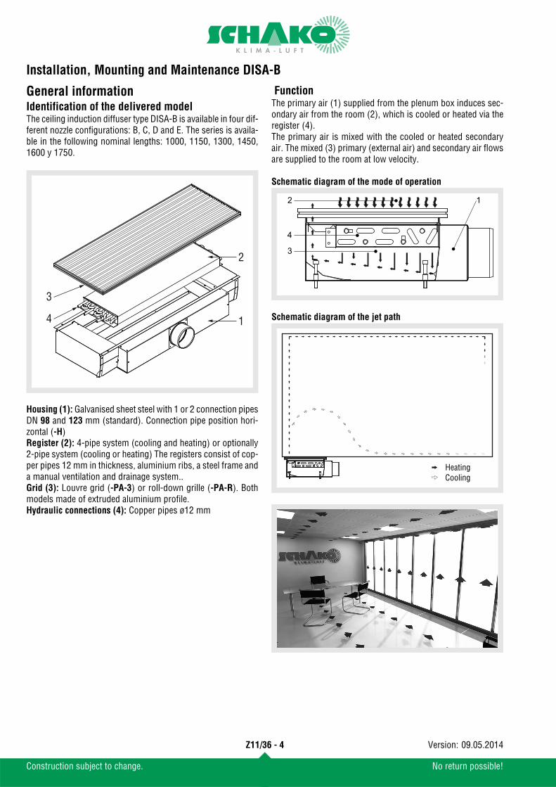
General informationIdentification of the delivered modelThe ceiling induction diffuser type DISA-B is available in four dif-ferent nozzle configurations: B, C, D and E. The series is availa-ble in the following nominal lengths: 1000, 1150, 1300, 1450,1600 y 1750.
Housing (1): Galvanised sheet steel with 1 or 2 connection pipesDN 98 and 123 mm (standard). Connection pipe position hori-zontal (-H)Register (2): 4-pipe system (cooling and heating) or optionally2-pipe system (cooling or heating) The registers consist of cop-per pipes 12 mm in thickness, aluminium ribs, a steel frame anda manual ventilation and drainage system..Grid (3): Louvre grid (-PA-3) or roll-down grille (-PA-R). Bothmodels made of extruded aluminium profile.Hydraulic connections (4): Copper pipes ø12 mm
FunctionThe primary air (1) supplied from the plenum box induces sec-ondary air from the room (2), which is cooled or heated via theregister (4).The primary air is mixed with the cooled or heated secondaryair. The mixed (3) primary (external air) and secondary air flowsare supplied to the room at low velocity.
Schematic diagram of the mode of operation
Schematic diagram of the jet path1
2
3
4
1
3
4
2
Heating Cooling

Installation, Mounting and Maintenance DISA-B
Z11/36 - 5
Construction subject to change. No return possible!
09.05.2014Version:
Installation and commissioningOperating conditionsPrior to installation or commissioning of the device, the follow-ing operating conditions must be observed:
Material reception Upon reception of the materials, the components must be care-fully checked, in order to guarantee that no transport damagehas taken place. Moreover, the dimensions, composition andnumber of the identification sticker must be checked as towhether they are as ordered.
Identification sticker:
To prevent possible damage during transport, the devices willbe delivered ex works on pallets (that correspond to the partic-ular weight and dimensions) wrapped with tapes and transpar-ent plastic film. It is recommended leaving this protection inplace until the device is commissioned. The openings of thepipes should be closed with dust caps to avoid dust and entry ofdirt.
Transport, lifting and handlingTransport and handling of the unitshall take place in the position inwhich the unit is to be built in later on,unless expressly stated otherwise onthe unit.Transport, unloading and lifting ofthe unit shall take place with the nec-essary care and using tools that areappropriate for the weight and dimensions.
WeightsDISA-B
(1) Standard unit: housing + slot + grille and heat exchanger (empty)
StorageIf the device is not installed immediately after its reception, itmust be stored according to the following instructions:
- Coolant or heating fluid: water or glycols (ethylene or propylene) at a concentration below 60%.
- Water inlet temperature: above the dew point up to 80°C(Please note that some connectors do not work at watertemperatures above 65°C)
- Air inlet temperature: from 2 to 45°C- Max. operating pressure: 8 bar / 125°C.
- HT: 4-pipe system- PA: Louvre grid PA -extruded aluminium profile-- B: Nozzle configuration -B-- 1000: Nominal length -1000 mm-- 1150: Total length -1150 mm-- M: Position of primary air plenum box -central-- WS1: Water connection -left-- AS1: Number of connection pipes -1 connection pipe arranged cen-- 123: Diameter of the connection pipes -123 mm -
To prevent deposits and corrosion, the quality of the water for filling the registers mustcomply with regulations VDI 2035 and DIN 50930.For optimum operation in cooling mode, a mini-mum pressure loss of 90 Pa is recommended forthe primary air.
SCHA
KO Ib
eria
, S.L
. - P
ol. I
nd. R
ío G
álle
go, C
/B, n
ave
3 - E
-508
40 S
an M
ateo
de
Gálle
go.Model / Modelo / Modell
DISA-B-HT-PA-B-1000-1150-M-WS1-AS1-123
Order nr. / Nº Pedido / Auftragsnr: 2198/09 Date / Fecha /Datum: 22/10/2013 Reference / Referencia / Referenz: Sala 1 Hospital Clínico Comments / Observaciones / Bemerkungen:
Read manual of instructions / Lea el manual de instrucciones / Betriebs- und Wartungsvorschriften beachten.Do not drill the machine / Maschine nicht durchbohren / No taladrar la máquinaSpecial attention in the connection nuts-coil / Besondere Vorsicht an der Registerverschraubung/ Especial cuidado en la conexión tuercas-batería .Recycle or arrange the residues according to the current rules / Recicle o gestione los residuos según la normativa vigente. Bitte, entsprechend der gültigen Gezetzgebung recyclen.
NL 1000 1150 1300 1450 1600 1750
Weights (1) (kg) 18,5 21 23 25,5 28 30,5
- The device must be stored at a dry, clean, safe locationwhere no damage to the device can occur, i.e., outsidecorrosive atmospheric influences.
- Leave the protections attached ex works (film, tapes, pal-lets, etc.) on the device, unless they have already been re-moved beforehand.
- Cover the device with tarpaulins, in order to protect it fromdust, moisture and extreme temperatures.
- Entries, openings and pipes must be hermetically sealedwith dust caps.
Should manufacture-related damage be detectedon the device, please contact your local sales officeprior to installation.
The unit shall only be held in position or moved by holding on to the housing. The weight must notrest on the water connections.SCHAKO cannot be held liable for damage to theunit caused by improper handling or handling notmentioned here, loading or unloading.

Installation, Mounting and Maintenance DISA-B
Z11/36 - 6
Construction subject to change. No return possible!
09.05.2014Version:
InstallationThe floor induction diffuser type Maintenance DISA-B is partic-ularly suitable for horizontal installation in false floors. The de-vices must not be installed in places with extreme moisture (e.g.laundries or swimming pools), aggressive media, with high dustformation, outdoors or in places subject to explosion hazards.For correct installation, the following instructions must be fol-lowed:
MountingThe device is fastened to the floor by means of adjusting legs and levelled (1).
During mounting the end of the register pipes must be sealed toprotect them from dust and dirt.
Once the device has been aligned on the floor, it can be fixed tothe floor by means of the delivered mounting plates (2) and fas-tening elements approved by the building supervisory authori-ties and adjusted in height later on.
Hydraulic connections
- Make sure that places that are intended as openings for airadmission and air discharge are free of pipes, electric cables,crossbeams, stands, etc.
- Install the unit at a site that has good air quality.
- Make sure that the floor or false floor correspond to theweight of the device and also allow correct mounting of thefastening elements.
- The installation site must have sufficient space and the nec-essary resources for carrying out mounting and maintenanceactivities of all device components. Make sure that the valvesare easily accessible.
(1)
33 33
275
For the installation of the device, use adequate tools,devices and materials and observe the safety regula-tions and other current regulations.SCHAKO cannot be held liable for damage resultingfrom faulty installation or the use of unsuitable fas-tening devices.
1
2
4491
187234
98125
44234
125
2875
171218
98 125
28218
125
Heating Cooling
DISA-B-HT-...-WS1 / -WS3(4-pipe)
DISA-B-H...-WS1 / -WS3(2-pipe)
DISA-B-HT-...-WS2 / -WS4(4-pipe)
DISA-B-H...-WS2 / - WS4(2-pipe)
Heating Cooling

Installation, Mounting and Maintenance DISA-B
Z11/36 - 7
Construction subject to change. No return possible!
09.05.2014Version:
Amount of water of the registers:
The connection of the hydraulic connections can be done by sol-dering, pressing (in connection with supporting sleeves) or by means of flexible hoses resistant to oxygen diffusion and push-fit systems. The use of flexible hoses is subject to the manufac-turer's specification.When making the hydraulic con-nections, you have to use suitabletools to avoid excessive tighten-ing or twisting of the registerconnections.
To ensure that no air remains inthe register and in the hydraulic circuit, the air is drained bymeans of ventilation units present in the register. If the unit is to be installed at a location having temperatures be-low zero degrees, glycol must be admixed to the coolant in asuitable ratio, to ensure that the freezing point of this liquid al-ways stays below the minimum temperature of the operatingsite. Please note that the use of an antifreeze necessarily resultsin a loss in performance of the register.
Connecting the air ductsThe air ducts are attached by using pipe clamps, fixing lugs orthe like.
Optionally, a rubber lip seal canbe installed on the connectionpipe, to ensure tightness be-tween the device and the pipes.
Mounting accessoriesValves and actuatorsValves and actuators shall not be installed ex works. During in-stallation the manufacturer's specifications must be observed.
Temperature controlsThe temperature controls are mounted in accordance with theselected model. This is why the instructions enclosed with eachmodel must be followed. However, in order to achieve optimummeasurement by the sensors, the following basic informationshould be observed:
Condensate monitorThe installation of a condensate monitor depends on the select-ed model. Please follow the instructions enclosed with eachmodel.
Amount of water (litres)
NLDISA-B-HT
DISA-B-HHeating Cooling
1000 0,39 1,16 1,541150 0,46 1,36 1,811300 0,53 1,55 2,071450 0,59 1,75 2,331600 0,66 1,95 2,591750 0,72 2,14 2,86
In order to achieve a uniform cooling capacity, thefloor induction diffusers type Maintenance DISA-Bshould be connected to the cold water distributionsystem in parallel.The floor induction diffusers type Maintenance DISA-B are induction devices for "dry cooling". To avoidcondensation, the cold water supply temperaturemust be selected such that it does not fall below thedew point, which may make it necessary to installprotective devices (condensate monitors).
- Do not mount the temperature control close to or above aheat source (direct sunlight, lamps, television sets, radia-tors, etc.), in places with draught air or directly oppositeto an air diffuser grille.
- Temperature controls must be mounted at least 1.5 me-tres above the floor.
- Mounting temperature controls on walls toward the out-doors should be avoided.
Prior to drilling, make sure that at the location in the wall where the temperaturecontrol is attached no electric cables are present.
Faulty mounting of the sub-assemblies and of the accessories of the unit can result in a substantialpower loss of the unit.

Installation, Mounting and Maintenance DISA-B
Z11/36 - 8
Construction subject to change. No return possible!
09.05.2014Version:
ChecksPrior to commissioning, the following items must be checked orguaranteed:
During commissioning itself, the following items must be guar-anteed:
MaintenanceFor reasons of safety, the power supply and hydraulic circuitmust be disconnected prior to any maintenance activity. If theunit was operated in heating mode, you have to wait until theregister has cooled down.
Disassembling the unitsPA
Connection covers
Registers
Cleaning the grillesClean them with an industrial vacuum cleaner or steam cleaneror by spraying them with a non-aggressive cleaner.
- Hydraulic connections were tightened properly and exhib-it no leaks.
- Connecting and fastening elements have been sufficientlytightened.
- Adequate access for carrying out the maintenance activi-ties has been provided.
- Use the on-site ventilation device to ensure that no air re-mains in the register and the circuit.
- The connecting and fastening elements have been suffi-ciently tightened.
- In heating mode, the temperature of the discharged sup-ply air is not above 40°C.
- In type PA-3, remove screws and grilles (see figure).- In type PA-R, roll up the grille and remove it.
After these items have been taken care of,the correct fastening of the device must be checked.
When performing maintenance activities, it is rec-ommended wearing personal protective equip-ment, in order to avoid cuts and other injuriesproduced by sharp and pointed parts.
- Remove the screws unscrewing them with an Allenwrench
- Remove the covers of the hydraulic connections
- Before removing the register, make sure that the hydrauliccircuits are closed.
- Disconnect the register from the hydraulic system.- Remove the two screws on the register sides unscrewing
them with an Allen wrench and remove the register.

Installation, Mounting and Maintenance DISA-B
Z11/36 - 9
Construction subject to change. No return possible!
09.05.2014Version:
Air ducts and plenum boxClean them with an industrial vacuum cleaner or steam cleaneror by spraying them with a non-aggressive cleaner.
RegistersTo guarantee the technical characteristics of the device, the reg-isters and heat exchangers must be kept in good clean condi-tion. To ensure this, the following maintenance activities mustbe carried out:
- Remove the secondary air grille as described above. - If the register is dirty, clean it by spraying it with water or
compressed air or by evacuation.- Please do not use any scouring agents for cleaning since
they may impair or damage the materials of theMainte-nance DISA-B (galvanised steel, aluminium and copper)and the surface coatings (paints and anodised surfaces).
- If there are larger differences in distance between the ribs,they must be "aligned".
- Ventilate the hydraulic circuits of the register. In doing so,watch out for possible leaks of the hydraulic system.
For reasons of safety, the power supply and hydrau-lic circuit must be disconnected prior to any main-tenance activity.
When decommissioning the unit or shutting itdown for a longer period in winter, the water mustbe drained from the unit, in order to avoid damageto the register due to the formation of ice. If youwant to use antifreezes, you must first determinethe freezing point.After recharging the register, the installer has tomake sure by means of on-site ventilation devicesthat no air remains in the hydraulic circuit.

Installation, Mounting and Maintenance DISA-B
Z11/36 - 10
Construction subject to change. No return possible!
09.05.2014Version:
Checking the primary volumetric flowThe supplied primary volumetric flow can be simply checked bychecking the static pressure with a Pa meter and the measuringtube available from us as accessory. The pressure transducer is in the area of the hydraulic connec-tions. After removing the sealing plug, a connection to a Pa me-ter can be established by means of a hose 8 mm in diameter.After the measurement is complete, the pressure transducermust be closed again. The values read on the meter and the following formula can beused to to determine the volumetric flow:
V [l/s] = Primary air flowPs [Pa] = Static pressure
The K value is taken from the following table:
Air density:: ρ = 1.2 kg/m3
Nozzle configuration BNozzle configuration C
NL (mm)
Nozzle config-uration
1000 1150 1300 1450 1600 1750
B 0,38 0,46 0,53 0,61 0,67 0,75
C 0,70 0,85 0,97 1,12 1,24 1,39
D 1,06 1,28 1,46 1,68 1,86 2,08
E 1,79 2,16 2,47 2,84 3,15 3,52
V K Ps=
The Pa meter is not included in the delivery.
Vzu (m3/h)0 20 40 60 80 100 200
020
4060
8010
020
030
0
�P(Pa.)
850-
B10
00-B
1150
-B13
00-B
1450
-B16
00-B
Vzu (m3/h)0 20 40 60 80 100 200
020
4060
8010
020
030
0
�P(Pa.)
850-
C10
00-C
1150
-C13
00-C
1450
-C16
00-C

Installation, Mounting and Maintenance DISA-B
Z11/36 - 11
Construction subject to change. No return possible!
09.05.2014Version:
Nozzle configuration D Nozzle configuration E
VZU [m3/h] = supply air volumeΔP [Pa] = pressure loss
Troubleshooting
Vzu (m3/h)0 20 40 60 80 100 200
020
4060
8010
020
030
0
�P(Pa.)
850-
D10
00-D
1150
-D13
00-D
1450
-D16
00-D
Vzu (m3/h)0 20 40 60 80 100 200
020
4060
8010
020
030
0
�P(Pa.)
850-
E
1000
-E
1150
-E
1300
-E
1450
-E
1600
-E
Problem Possible cause Solution
The unit does not cool or heat suffi-ciently
Primary air volume not present or too low Check primary air volume
Air inlet and outlet of the inner unit clogged Remove foreign material and clean the unit
Air in the hydraulic systemVentilation of the hydraulic systemPlease inform the installer
Installed unfavourably or malfunctions at the temperaturecontrol or sensor
Install thermostat in a different place
Clogging of the cooling/heating register Clean the register in accordance with themaintenance instructions
The unit is losing water
Condensate in the register Modify the water inlet temperature
The water circuit of the register is leaking
Please inform the installerRegister damaged
Incorrect valve or hydraulic connection
The unit is working with too muchnoise
The air intake or air blow openings or the lines are clogged. Remove foreign material and clean the unit
Loose screws and fastening elements Tighten screws
Foreign material or dirt on register surfaceRemove foreign material by careful brushing
Primary air volume too large for selected configuration. Check primary air volume