installation and initial performance of 60” ads n...
TRANSCRIPT

Research, Development and Technology
MoDOT
RDT 02-07
Installation and Initial Performance of 60” ADS N-12HC
HDPE Pipes
June, 2002
RI 01-037
R

TECHNICAL REPORT DOCUMENTATION PAGE
1. Report No. 2. Government Accession No.
3. Recipient's Catalog No.
RDT02-007/RI01-037 4. Title and Subtitle 5. Report Date
June, 2002 6. Performing Organization Code
Installation and Initial Performance of 60"ADS N-12HC® HDPE Pipes
MoDOT 7. Author(s) 8. Performing Organization Report No.Michael R. Blackwell, Intermediate Research Technician And Xinge (Julie) Yin, Research Assistant
RDT02-007
9. Performing Organization Name and Address 10. Work Unit No. 11. Contract or Grant No.
Missouri Department of Transportation Research, Development, and Technology P.O. Box 270 - Jefferson City, MO 65102 12. Sponsoring Agency Name and Address 13. Type of Report and Period Covered
Construction Report 14. Sponsoring Agency Code
Missouri Department of Transportation Research, Development and Technology Division P. O. Box 270 - Jefferson City, MO 65102 MoDOT 15. Supplementary Notes The investigation was conducted in cooperation with the U. S. Department of Transportation, Federal Highway Administration. 16. Abstract Highway drainage pipes are built using metal, clay, concrete or plastic. High-density polyethylene (HDPE) is being used as drainage pipe because it is lightweight, corrosion resistant, easy to install, and has a low maintenance cost. However, as a newer material, the long-term performance of HDPE pipe is still under evaluation. Polyethylene pipe has been installed in Missouri since 1983 and continues to perform. In 1999, the first 60" (1500mm) N-12 HC® HDPE pipe was installed. So far, two 60" HDPE pipes were installed as crossroad culverts to evaluate their performances. For such large diameter flexible pipe, one main concern is its wall stability. This study approached this issue by monitoring the pipe deflections and joint separations. It was found out that installation procedure plays an important role. Improper installation caused excessive pipe deflection and joint separation later on, and will shorten the pipe service life accordingly. 17. Key Words 18. Distribution Statement High-density Polyethylene (HDPE), Crossroad Culvert, Installation, Compaction, Deflection
No restrictions. This document is available to the public through National Technical Information Center, Springfield, Virginia 22161
19. Security Classification (of this report)
20. Security Classification (of this page)
21. No. of Pages
22. Price
Unclassified Unclassified 17 w/o Appendices
Form DOT F 1700.7 (06/98)

Research Investigation 01-037
INSTALLATION AND INITIAL PERFORMANCE OF 60"ADS N-12HC® HDPE PIPES
MISSOURI DEPARTMENT OF TRANSPORTATION RESEARCH, DEVELOPMENT AND TECHNOLOGY BUSINESS UNIT
BY: Michael R. Blackwell, Intermediate Research Technician And Xinge (Julie) Yin, Research Assistant
Acknowledgements to:
John D. Wenzlick, Research and Development Engineer Patty Brake Lemongelli, Director/Research
Patrick X. Collings, P.E., ADS Inc. Daniel Currence, P.E., ADS Inc.
JEFFERSON CITY, MISSOURI
DATE SUBMITTED: June 1 2001
The opinions, findings and conclusions expressed in this publication are those of Advanced Drainage System (ADS) Management, the principal investigator, and the Research, Development and Technology Business Unit (RDT) of the Missouri Department of Transportation (MoDOT). They are not necessarily those of the U.S. Department of Transportation (DOT), Federal Highway Administration (FHWA). This report does not constitute a standard of regulation.

Acknowledgements RDT (Research, Development, and Technology) would like to express our thanks and appreciation to ADS (Advanced Drainage Systems) for their assistance in this joint effort. Special thanks to Patrick X. Collings, P.E., Manager-Applications Engineering ADS, Inc., and Daniel Currence, P.E., Regional Engineer ADS, Inc., their knowledge and expertise are valuable to this project.
Executive Summary In recent years, MoDOT has installed two 60" (1500mm) N-12 HC® HDPE (High Density Polyethylene) pipes as crossroad culverts to evaluate their performances. For such large diameter flexible pipe, one main concern is its wall stability. This study approached this issue by monitoring the pipe deflections. MoDOT District 7 maintenance crews installed the first pipe (referred to as Pipe 1 in this report) in June of 1999 on Route B, St. Clair County. The second 60" pipe (referred to as Pipe 2 in this report) was installed in August 2000 on Route FF, Franklin County by Krupp Construction. RDT personnel observed both installations. Since the installations, pipe deflections have been monitored. Based on field observations and data analysis, this study concludes that Pipe 2 is performing better than Pipe 1. The most distinguishable factor, which may contribute to this performance difference, is the different compactions these two pipes experienced during the installations. Pipe 2 had much better compaction than Pipe 1 both in bedding and backfilling procedures. AASHTO Section 30(Installation) now recommends the deflection be less than 5% of the actual inside diameter 30 days after installation. MoDOT Standard Specifications 730.7 specifies that the internal diameter of the pipe should not be reduced by more than 5% of its base inside diameter when measured not less than 30 days following completion of installation. 42 days after installation Pipe 1 had a maximum deflection of 7.3%, exceeding AASHTO Section 30 recommendations and MoDOT specifications, which is not acceptable. Two years and four months after the installation, the maximum deflection was measured as 8.4%, which is not acceptable, either. Since excessive deflection may lead to pipe cracking, Pipe 1 may require maintenance or replacement sooner than Pipe 2 due to installation procedures, and most likely not due to the actual material or manufacturing of the pipe itself. Pipe 2 did not get a perfect installation, but it is performing well. The two-week-after-installation deflection was rather small. One year after the installation, the maximum deflection was 5%, and the deflections at other points were considerably lower. Both pipes have joint separation. Pipe 1 had a maximum separation of 1 3/8" two years after installation, while Pipe 2 had a 2" maximum separation one year after its installation. But considering the bell overlaps the spigot by 9.57", there may be no threat of leaking. Existence of long-term undermining is not known at this time.
Both pipes should be inspected yearly to monitor their progress and be documented accordingly. Any immediate repairs necessary will then be forwarded to the appropriate maintenance personnel. If there are other large size HDPE pipes to be installed in Missouri, this study recommends proper installation procedures be followed.

Table of Contents
Acknowledgements…………………………………………………………………………
i
Executive Summary……………………………………………………………………….
ii
Table of Contents………………………………………………………………………….
iii
List of Figures …………………………………………………………………………….
iv
List of Tables……………………………………………………………………………...
v
Introduction………………………………………………………………………………..
1
Objectives………………………………………………………………………………….
1
Technical Approach……………………………………………………………………….
2
Discussion and Results…………………………………………………………………….
2
Installation……………………………………………………………………………
3
In-service Performance………………………………………………………………..
8
Conclusions………………………………………………………………………………...
15
Recommendations………………………………………………………………………….
17
Reference…………………………………………………………………………………..
17
Appendix

List of Figures
Figure 1 N-12 HC® HDPE 60" Pipe……………………….……….….……….… 2 Figure 2 Preparations of Pipe 1 Bedding Foundation…………………………….. 3 Figure 3 Pipe 1 Bedding Finished to Line and Grade…………………………….. 4 Figure 4 Laying Down Pipe 1……………………………………………………... 4 Figure 5 Assembling Pipe 1 Joints………………………………………………… 5 Figure 6 Placing Backfill Above Pipe 1 Midpoint………………………………… 5 Figure7 Working Native Backfill Under Pipe 1 Haunches………………………. 6 Figure 8 Pipe 2 Bedding Compaction…………………………………………….. 7 Figure 9 Narrow Trench of Pipe 2………………………………………………… 7 Figure 10 Pipe 2 Backfill Compaction Above Pipe Midpoint……………………… 8 Figure 11 Pipe 1 Vertical Deflection……………………………………………….. 11 Figure 12 Pipe 1 Horizontal Deflection…………………………………………….. 11 Figure13 Pipe 1 Vertical Deflection at Three Time Points………………………… 12 Figure 14 Pipe 1 Horizontal Deflection of Three Time Points……………………... 13 Figure 15 Pipe 2 Vertical Deflections………………………………………………. 14 Figure 16 Pipe 2 Horizontal Deflections………………………………...…………. 15 Figure 17 Structure of Deflection Meter (in Appendix) Figure 18 Measuring Horizontal Diameter with Deflection Meter (in Appendix) Figure 19 Measuring Vertical Diameter with Deflection Meter (in Appendix)

List of Tables
Table 1 Pipe 1 Initial Deflection…………………………………………………... 8 Table 2 Pipe 1 Deflection on 7/29/1999 - 42 days after installation……………… 9 Table 3 Pipe 1 Deflection on 10/07/1999 - 82 days after installation…………….. 9 Table 4 Pipe 1 Deflection on 02/09/2000 - 8 months after installation…………… 9 Table 5 Pipe 1 Deflection on 05/09/2000 - 11 months after installation………….. 9 Table 6 Pipe 1 Deflection on 07/29/2000 - 13 months after installation………….. 10 Table 7 Pipe 1 Deflection on 03/12/2001 - 20 months after installation………….. 10 Table 8 Pipe 1 Deflection on 09/11/2001 - 26 months after installation………….. 10 Table 9 Pipe 1 Deflection - 26 months after installation (measured with tape)….... 10 Table10 Pipe 2 Deflection 09/12/2001 - 1 year after installation………………...... 14
INTRODUCTION
Predictably efficient and effective highway drainage is a common goal of state departments of transportation. (NCHRP Synthesis 254, p.3). The estimate of years of reliable low maintenance service, is conditioned by service experience of drainage pipes, choice of pipe materials, environmental considerations, regional construction practice and economic constraints. Highway drainage pipes are built using metal, clay, concrete or plastic. Depending upon the type of pipe materials placed, there are number of factors which influence performance. MoDOT, as well as other local, state and federal agencies, shoulder the burdens of choosing the most efficient pipes and culverts for particular drainage applications. During the decision making, one most important concern is that the pipes must be sufficiently durable to meet the expected longevity of the desired service life, thus the drainage structure materials must be compatible with local and regional environments to meet this goal. Since the early 1930’s, MoDOT has continued to conduct various studies to monitor and evaluate the durability and performance of culvert pipe materials used in Missouri (Summary of Missouri Culverts Studies, p.1). Metal pipes are considered highly susceptible to corrosion, and a majority of the metal or steel pipe failures can be attributed to corrosion. Concrete pipes are susceptible to corrosion due to exposure to a low PH or the presence of sulfates in soil or water. High-density polyethylene (HDPE) is being used as drainage pipe because it is lightweight, corrosion resistant, easy to install, and has a low maintenance cost. Polyethylene pipe has been installed in Missouri since 1983 and continues to perform. In 1999, the first 60" HDPE pipe was installed in St. Clair County, Missouri. Before this, the HDPE pipes being installed had smaller diameters because there is no AASHTO designation for plastic pipes with diameters larger than 48". One year later, another 60" HDPE pipe was installed in Franklin County, MO. HDPE pipes were chosen mainly because of the corrosive environment at these two locations. These two pipes were manufactured by ADS (Advanced Drainage System, Inc.). MoDOT and ADS agreed to install these two pipes as crossroad culverts and to evaluate their performances. For such large diameter flexible pipe, one main concern is its wall stability. This study approached this issue by monitoring the pipe deflections. OBJECTIVES The objective of this study is to document and analyze the installation and performance of two 60" HDPE pipes, in order to determine what makes them perform well and what does not. This objective fits into the bigger picture to track and monitor the performance of different pipe materials to install the most cost-effective pipes given the location and conditions. To accomplish these objectives, the following tasks were performed:
1. Observed and documented HDPE pipe installations. 2. Collected pipe deflection data as the basis for performance analysis.

3. Analyzed field data. 4. Developed report for up-to-date performance of the pipes. 5. Recommend future continuing performance monitoring.
TECHNICAL APPROACH The technical approach for this study included making observations during installation, measuring the pipe deflection and joint separation, and analyzing the data. Since 2001, the deflections measurements have been taken with a RDT device Deflection Meter (See Appendix for the picture and operations). ADS had some concerns about the of Meter measurements consistency with their tape measurements. In an effort to address these concerns, measurements using a tape measure were taken once by an ADS representative and compared to the meter. Since the tape measure results were very close to Deflection Meter measurements, there is no dispute to use Meter measure data for this report. The Meter can control vertical and horizontal dimensions precisely when measuring the deflections, and it provides reliable and consistent data for the purpose of this study. DISCUSSION AND RESULTS MoDOT and ADS agreed to install a 60" (1500mm) N-12 HC® (see Figure 1) HDPE pipe as a crossroad culvert on Route B to evaluate its performance. For such large diameter flexible pipe, one main concern is its wall stability. The N-12 HC® pipe features smooth inner and outer walls, and honeycomb section using closely spaced circular ribs for added ring stiffness and structural strength.
Figure 1. N-12 HC® HDPE 60" Pipe
The first pipe was installed in June of 1999 on Route B, St.Clair County, and it will be referred as Pipe 1 in this report. ADS supplied 60 feet (18m) of the pipe to the project site for installation by MoDOT District 7 maintenance crews. This HDPE pipe was chosen to replace the old 60-foot-long 10 gauge galvanized CMP (Corrugated Metallic-coated Steel Pipe), which was originally installed around 1956, and had failed due to corrosion. The second 60" HDPE pipe was installed in August 2000 on Route FF, Franklin County, as part of a culvert replacement project. It will be referred as Pipe 2 in this report. Krupp Construction, the contractor, performed the installation of this 60-feet pipe.

INSTALLATIONS Installation is critical for the service performance of pipes. A literature review showed that AASHTO, neighboring state DOTs and MoDOT have slightly different requirements for HDPE pipe installations. For the purpose of this study, the actual installations for these two pipes are described in the following sections, and a comparison with MoDOT standard specifications are made later on. Pipe 1 Installation (St. Clair County) A 4-man MoDOT maintenance crew performed the installation with a 655D Ford backhoe. The installation was completed and open to traffic in one day. Representatives from ADS, MoDOT RDT personnel, and District 7 Operations and Maintenance Engineers observed the installation. Installation began on the morning of June 17, 1999. The pavement was cut 10 feet wide over the culvert. The existing CMP was removed by 11:00 am and the trench was excavated to the proper width by 12:00 pm. During the excavation of the existing structure and preparation of the trench, a large boulder was removed under the roadway at the upstream end of the culvert and backfill material was worked into the void, however, this may eventually effect the pavement above. The foundation was prepared by raking to grade (see Figure 2). After lunch the crew installed a 4" thick layer of ¾" (-) stone bedding (see Figure 3) which was loosely compacted by hand to the proper grade. The bedding was an AASHTO A-2 material and also met MoDOT bedding materials requirements.
Figure 2. Preparations of Pipe 1 Bedding Foundation

Figure 3. Pipe 1 Bedding Finished to Line and Grade The pipe was laid to grade with bell holes dug at each bell. The joints were assembled by laying the downstream pipe and lowering the upstream pipe with a backhoe, aligning the upstream pipe as it was lowered in place (see Figure 4 and Figure 5). The joints were lubricated prior to installation and pulled together with the backhoe. After all sections of pipe were laid, a chain and come-along were used to pull the joints tight. A visual inspection of the joints showed the maximum opening of any of the joints was approximately 1/2".
Figure 4. Laying Down Pipe 1
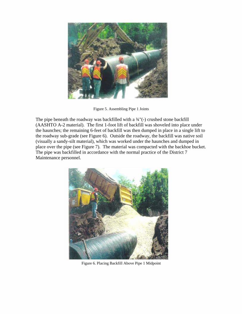
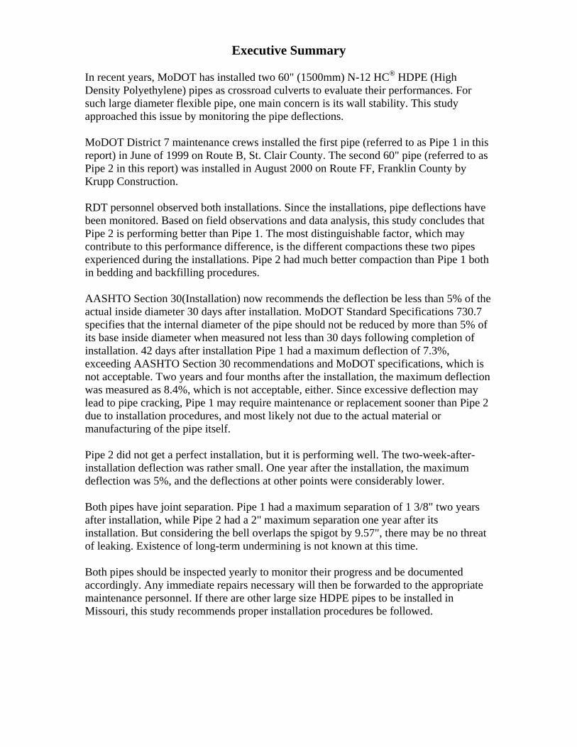
Figure 5. Assembling Pipe 1 Joints
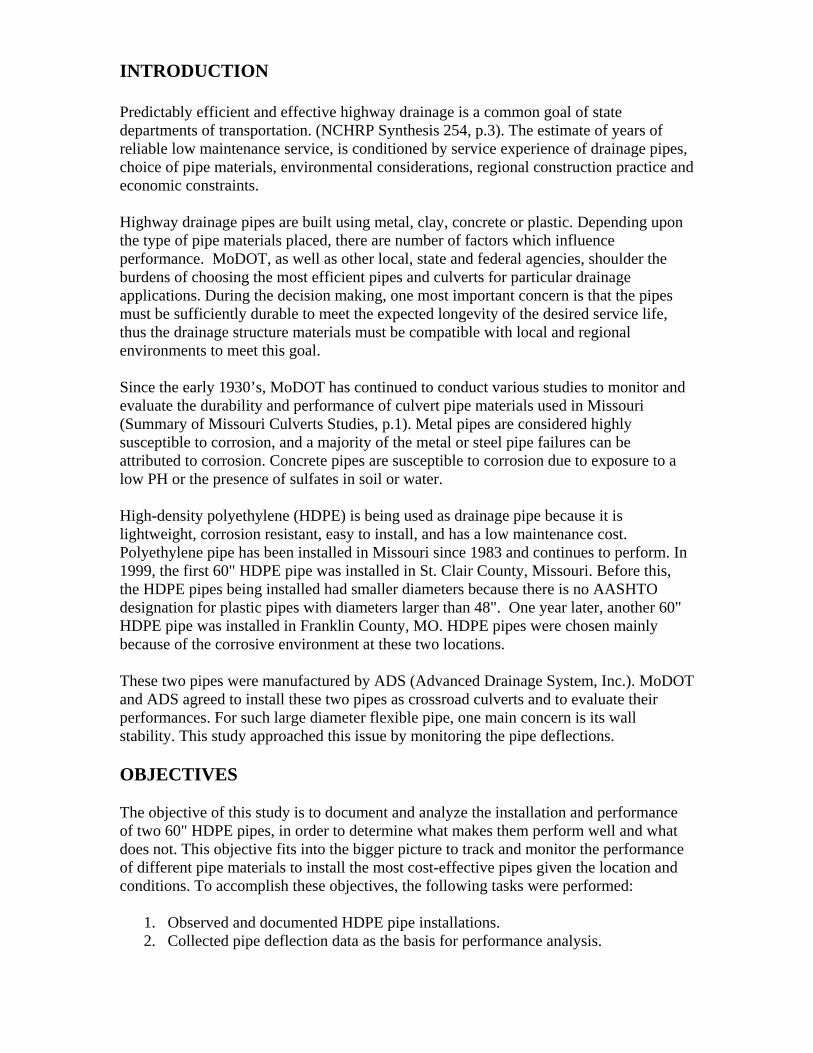
The pipe beneath the roadway was backfilled with a ¾"(-) crushed stone backfill (AASHTO A-2 material). The first 1-foot lift of backfill was shoveled into place under the haunches; the remaining 6-feet of backfill was then dumped in place in a single lift to the roadway sub-grade (see Figure 6). Outside the roadway, the backfill was native soil (visually a sandy-silt material), which was worked under the haunches and dumped in place over the pipe (see Figure 7). The material was compacted with the backhoe bucket. The pipe was backfilled in accordance with the normal practice of the District 7 Maintenance personnel.
Figure 6. Placing Backfill Above Pipe 1 Midpoint

Figure 7. Working Native Backfill Under Pipe 1 Haunches After the backfilling was finished, the roadway was completed with a cold asphalt patch. There was no end protection for the pipe. Measured at the shoulder to the finished pavement surface, the cover depth over the pipe was found to be 22" (550mm) at the upstream end and 23.4" (595mm) at the downstream end. The depth of the cover met MoDOT Standard Specifications requirement (Missouri Standard Specifications for Highway Construction, Section 730). After the installation the roadway was opened to traffic. The installation was completed in one day with relatively little equipment. The crew installing the pipe indicated they had laid a 60" RCP (Reinforced Concrete Pipe) on the same road the previous week using the same installation method. They commented positively on the ease of installation of the HDPE pipe and the quality of the HDPE pipe joints. Pipe 2 Installation (Franklin County) Installation began around 9:00 a.m. on the morning of August 28, 2000, and was performed by Krupp Construction. The installation was completed and open to traffic within six hours. Representative from ADS, MoDOT RDT personnel, and MoDOT and District 6 Operations and Maintenance Engineers observed the installation. The pavement next to the old pipe was cut open; it took longer than expected since there was storm water backed upstream in the channel. Near 1:00 p.m., the trench cut was completed and the sand bedding was placed in the trench. The two outside 1/3’s of the trench bedding was compacted with 4 or 5 passes with the vibratory compactor. The middle 1/3 of the trench was lightly compacted with a single pass of the vibratory plate compactor to provide a cushion for the pipe (see Figure 8). Visual checking indicated a good bedding compaction.

Figure 8. Pipe 2 Bedding Compaction Figure 9. Narrow Trench of Pipe 2 When the pipe was laid into the trench at approximately 1:45 p.m., however, the trench width was found out to be narrower than the minimum specified (see Figure 9). Due to urgency in getting the pipe installed and the roadway back open by 3:00 p.m., there was no time to widen the trench.
Due to the narrow trench, and trying to get the pipe installed and the roadway open to traffic, Krupp decided not to mechanically compact the 1" clean stones until the backfill was at, or above the midpoint of the pipe. The checking by ADS representative indicated that the backfill was likely being compacted in the haunch zone. The backfill above the pipe midpoint was compacted with the vibratory compactor (see Figure 10). The cover was measured with a tape. It was measured 28" between the top of the pipe and the proposed asphalt, which would equate 20" to the bottom of the asphalt pavement, which meets MoDOT standard specification requirement. End protection was provided for this pipe with aluminum end sections. Unfortunately, initial joint conditions after installation were not documented.

Figure 10. Pipe 2 Backfill Compaction Above Pipe Midpoint
IN-SERVICE PERFORMANCE Performance of Pipe 1 (St. Clair County) Approximately one week after the installation was completed and opened to traffic, ADS measured the deflection in the pipe. The inside diameter of the pipe prior to construction was 58.27" (1480mm) and the field measurements taken are as indicated in Table 1.
Table 1. Pipe 1 Initial Deflection
Pipe Section Location (from upstream end of section)
Measured Diameter (vertical) Deflection (%)
Upstream 5' 58.27" 1480mm 0.0% 15' 56.50" 1435mm 3.0% Middle 5' 55.98" 1422mm 3.9% 15' 55.51" 1410mm 4.6% Downstream 5' 56.73" 1441mm 2.6% 15' 58.27" 1480mm 0.0% The pipe had a maximum deflection of 4.6% shortly after installation. Most of the deflection was probably due to the low compaction effort of the installation, however, the deflection has been steadily increasing as shown in Table 2 through Table 9 (the numbers in red indicate maximum deflection), and Figure 11 and Figure 12.
Table 2. Pipe 1 Deflection on 7/29/1999 - 42 days after installation Measured Location Vertical Diameter Deflection (%) Horizontal Diameter Deflection (%)

1- Upstream 58.00" -0.4 59.50" 2.1 1 - Midspan 57.25" -1.7 61.00" 4.7 1 - Downstream 55.25" -5.2 62.50" 7.3 2 - Upstream 54.38" -6.7 62.50" 7.3 2 - Midspan 55.63" -4.5 62.00" 6.4 2 - Downstream 56.75" -2.6 61.25" 5.2 3 - Upstream 55.63" -4.5 61.50" 5.6 3 - Midspan 58.00" -0.4 60.38" 3.6 3 - Downstream 59.00" 1.3 60.00" 3.0
Table 3. Pipe 1 Deflection on 10/07/1999 - 82 days after installation Measured Location Vertical Diameter Deflection (%) Horizontal Diameter Deflection (%) 1- Upstream 58.50" 0.4 59.50" 2.1 1 - Midspan 56.50" -3.0 59.75" 2.6 1 - Downstream 55.50" -4.7 61.75" 6.0 2 - Upstream 54.50" -6.4 62.75" 7.7 2 - Midspan 55.50" -4.7 62.50" 7.3 2 - Downstream 56.00" -3.9 61.25" 5.2 3 - Upstream 55.50" -4.7 62.00" 6.4 3 - Midspan 57.50" -1.3 60.75" 4.3 3 - Downstream 59.00" 1.3 59.75" 2.6
Table 4. Pipe 1 Deflection on 02/09/2000 - 8 months after installation
Measured Location Vertical Diameter Deflection (%) Horizontal Diameter Deflection (%) 1- Upstream 58.20" -0.1 59.40" 2.0 1 - Midspan 56.50" -3.0 59.88" 2.8 1 - Downstream 55.10" -5.4 62.04" 6.5 2 - Upstream 54.00" -7.3 63.00" 8.2 2 - Midspan 55.00" -5.6 62.28" 6.9 2 - Downstream 55.90" -4 61.32" 5.3 3 - Upstream 55.38" -4.9 61.80" 6.1 3 - Midspan 57.60" -1.1 60.60" 4.0 3 - Downstream 58.68" 0.7 59.40" 2.0
Table 5. Pipe 1 Deflection on 05/09/2000 - 11 months after installation Measured Location Vertical Diameter Deflection (%) Horizontal Diameter Deflection (%) 1- Upstream 58.38" 0.2 60.00" 3.0 1 - Midspan 56.63" -2.8 60.00" 3.0 1 - Downstream 55.13" -5.4 62.13" 6.7 2 - Upstream 54.00" -7.3 63.00" 8.2 2 - Midspan 55.13" -5.4 62.38" 7.1 2 - Downstream 56.38" -3.2 61.63" 5.8 3 - Upstream 55.38" -4.9 61.83" 6.1 3 - Midspan 58.00" -0.4 60.75" 4.3 3 - Downstream 59.00" 1.3 59.50" 2.1
Table 6. Pipe 1 Deflection on 07/29/2000 - 13 months after installation
Measured Location Vertical Diameter Deflection (%) Horizontal Diameter Deflection (%) 1- Upstream 58.31" 0.1 60.00" 3.0 1 - Midspan 56.50" -3.0 60.00" 3.0

1 - Downstream 54.94" -5.7 62.00" 6.4 2 - Upstream 53.69" -7.9 63.13" 8.3 2 - Midspan 54.75" -4.0 62.63" 7.5 2 - Downstream 55.63" -4.5 61.38" 5.3 3 - Upstream 55.13" -5.4 62.00" 6.4 3 - Midspan 57.63" -1.1 60.56" 3.9 3 - Downstream 58.69" 0.7 59.56" 2.2
Table 7. Pipe1 Deflection on 03/12/2001 - 20 months after installation
Measured Location Vertical Diameter Deflection (%) Horizontal Diameter Deflection (%) 1- Upstream 57.63" -1.1 59.50" 2.1 1 - Midspan 56.00" -3.9 60.38" 3.6 1 - Downstream 54.63" -6.1 62.63" 7.5 2 - Upstream 53.38" -8.4 63.25" 8.8 2 - Midspan 54.50" -6.4 62.63" 7.5 2 - Downstream 55.38" -4.9 61.50" 5.6 3 - Upstream 55.00" -5.6 62.06" 6.5 3 - Midspan 57.50" -1.3 60.63" 4.1 3 - Downstream 58.63" 0.6 59.38" 2.1
Table 8. Pipe1 Deflection on 09/11/2001 - 26 months after installation
Measured Location Vertical Diameter Deflection (%) Horizontal Diameter Deflection (%) 1- Upstream 58.13" -0.2 60.00" 3.0 1 - Midspan 56.00" -3.9 60.25 3.4 1 - Downstream 54.75" -6.0 62.00" 6.4 2 - Upstream 53.38" -8.4 63.13" 8.3 2 - Midspan 54.50" -6.5 62.75" 7.7 2 - Downstream 55.38" -5.0 61.50" 5.5 3 - Upstream 55.00" -5.6 62.25" 6.8 3 - Midspan 57.50" -1.3 60.63" 4.1 3 - Downstream 58.63" 0.6 59.75" 2.5
Table 9. Pipe1 Deflection - 26 months after installation (measured with tape)
Measured Location Vertical Diameter Deflection (%) Horizontal Diameter Deflection (%) 1- Upstream 58.13" -0.2 60.13" 3.2 1 - Midspan 56.25" -3.5 60.38" 3.6 1 - Downstream 55.00" -5.6 62.13" 6.6 2 - Upstream 53.50" -8.2 63.25" 8.5 2 - Midspan 54.50" -6.5 63.00" 8.1 2 - Downstream 55.38" -5.0 61.50" 5.5 3 - Upstream 55.00" -5.6 62.00" 6.4 3 - Midspan 57.63" -1.1 60.75" 4.3 3 - Downstream 58.63" 0.6 59.75" 2.5
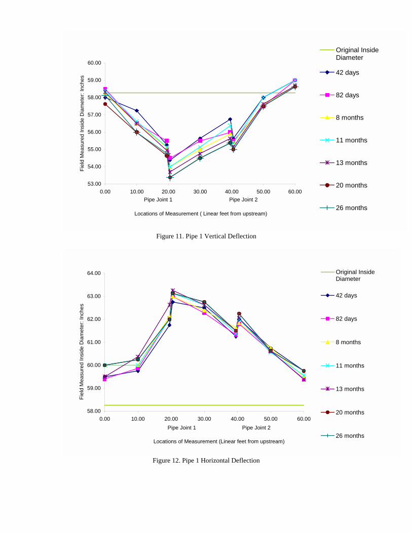
Figure 11. Pipe 1 Vertical Deflection
53.00
54.00
55.00
56.00
57.00
58.00
59.00
60.00
0.00 10.00 20.00 30.00 40.00 50.00 60.00Pipe Joint 1 Pipe Joint 2
Locations of Measurement ( Linear feet from upstream)
Fiel
d M
easu
red
Insi
de D
iam
eter
: Inc
hes
Original InsideDiameter
42 days
82 days
8 months
11 months
13 months
20 months
26 months
Figure 12. Pipe 1 Horizontal Deflection
58.00
59.00
60.00
61.00
62.00
63.00
64.00
0.00 10.00 20.00 30.00 40.00 50.00 60.00Pipe Joint 1 Pipe Joint 2
Locations of Measurement (Linear feet from upstream)
Fiel
d M
easu
red
Insi
de D
iam
eter
: Inc
hes
Original InsideDiameter
42 days
82 days
8 months
11 months
13 months
20 months
26 months

One noteworthy point is that the ADS representative attained the data in Table 9 using a tape measurement. Comparing the data in Table 9 and Table 8, there is no significant difference. Thus in this report, data from the Meter measurements is used to be consistent with future deflection measurements, which will be measured with the Deflection Meter. Judging from these tables and figures, it is apparent that the actual deflection has changed only in minimal increments since the installation of the pipe. Ever since the installation, the point of maximum deflection has been located at upstream part of section 2. After 42 days of installation, its vertical deflection was 6.7%, horizontal deflection was 7.3%. Thirteen months after, vertical deflection increased to 7.9% and horizontal deflection increased to 8.3%. After around 26 months, the vertical deflection is 8.4% and horizontal deflection stays as 8.3%. Most of the deflection occurred during the first 42 days after the installation. Comparing the deflections at 42-days, 13-months and 26-months after installation (see Figure 13 and Figure 14), it is obvious that the deflection has been slowing down, or has stabilized.
53.00
54.00
55.00
56.00
57.00
58.00
59.00
60.00
0.00 10.00 20.00 30.00 40.00 50.00 60.00Pipe Joint 1 Pipe Joint 2
Locations of Measurement (Linear feet from Upstream)
Fiel
d M
easu
red
Insi
de D
iam
eter
: Inc
hes
Original Inside Diameter 42 days13 months 26 months
Figure 13. Pipe 1 Vertical Deflection at Three Time Points

The of thjointtakenslighjointobsewas Thiscompopen Perf No drepreresuldiammeas(150
58.00
59.00
60.00
61.00
62.00
63.00
64.00
0.00 10.00 20.00 30.00 40.00 50.00 60.00Pipe Joint 1 Pipe Joint 2
Locations of Measurement (Linear feet from upstream)
Fiel
d M
easu
red
Insi
de D
iam
eter
: Inc
hes
Original Inside Diameter 42 days
13 months 26 months
Figure 14. Pipe 1 Horizontal Deflection of Three Time Points
joint separation was also monitored. At installation the maximum opening at either e joints was less than1/2". Twenty months after installation, the separation at the first was 1 3/8", and separation at the second joint was 1 3/4"; both measurements were near the six o’clock position facing downstream. This separation might be causing t undermining to the underlying bedding material because water leaks through the separation and trickles underneath the pipe. During heavy rain, some water was rved flowing from the bedding material underneath the outlet of the pipe. Also, there a slight depression on the road surface that had been patched late in the fall of 2000. patch already showed very slight depression. This is mostly likely due to the low action effort mentioned earlier, as the soil was still settling. Presently, the joint
ing decreased to 7/8" at the first joint and 1 3/8" at the second joint.
ormance of Pipe 2 (Franklin County)
eflection measurements were taken immediately after the installation. An ADS sentative took some measurements two weeks after installation, although these ts were not documented. However, the representative recalled the measured inside eters were about 59.25" to 59.5". Since the original inside diameter was not ured in the field before installation, it is assumed to be the target value of 59.06" 0mm), so these two-week-after deflections were negligible.
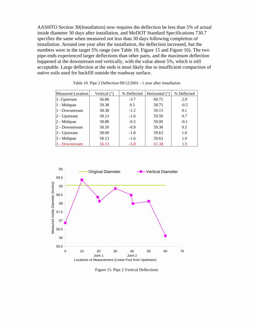
AASHTO Section 30(Installation) now requires the deflection be less than 5% of actual inside diameter 30 days after installation, and MoDOT Standard Specifications 730.7 specifies the same when measured not less than 30 days following completion of installation. Around one year after the installation, the deflection increased, but the numbers were in the target 5% range (see Table 10, Figure 15 and Figure 16). The two pipe-ends experienced larger deflections than other parts, and the maximum deflection happened at the downstream end vertically, with the value about 5%, which is still acceptable. Large deflection at the ends is most likely due to insufficient compaction of native soils used for backfill outside the roadway surface.
Table 10. Pipe 2 Deflection 09/12/2001 - 1 year after installation
Measured Location Vertical (") % Deflected Horizontal (") % Deflected 1- Upstream 56.88 -3.7 60.75 2.9 1 - Midspan 59.38 0.5 58.75 -0.5 1 - Downstream 58.38 -1.2 59.13 0.1 2 - Upstream 58.13 -1.6 59.50 0.7 2 - Midspan 58.88 -0.3 59.00 -0.1 2 - Downstream 58.50 -0.9 59.38 0.5 3 - Upstream 58.00 -1.8 59.63 1.0 3 - Midspan 58.13 -1.6 59.63 1.0 3 - Downstream 56.13 -5.0 61.38 3.9
Figure 15. Pipe 2 Vertical Deflections
55.5
56
56.5
57
57.5
58
58.5
59
59.5
60
0 10 20 30 40 50 60 70Joint 1 Joint 2
Locations of Measurement (Linear Foot from Upstream)
Mea
sure
d In
side
Dia
met
er (I
nche
s)
Original Diameter Vertical Diameter

One downthe s1" ato’clohighnega CON So fadefledistindiffecomp Pipespecwas enouPipe The back
58.5
59
59.5
60
60.5
61
61.5
62
0 10 20 30 40 50 60 70Joint 1 Joint 2
Locations of Measurement (Linear Foot from Upstream)
Mea
sure
d In
side
Dia
met
er (I
nche
s)
Original Diameter Horizontal Diameter
Figure 16. Pipe 2 Horizontal Deflections
year after the installation, the separation at the first joint (from upstream and facing stream) was 1" at the twelve o’clock location, 2" at the three o’clock location, 2" at
ix o’clock location, and 1 ½" at the nine o’clock location; at the second joint, it was the twelve o’clock location, 5/8" at the three o’clock location, 1 1/8" at the six ck location, and 1 ¼" at the nine o’clock location. These numbers are considered
, but it is unclear if the large separations have influenced the pipe performance tively.
CLUSIONS
r, the analysis shows that Pipe 2 is performing better than Pipe 1. Comparing the ction data around 1-year after installation, Pipe 1 had higher deflections. The most guishable factor, which may contribute to this performance difference, is the
rent compaction processes these two pipes experienced. Pipe 2 had better action than Pipe 1 both in bedding and backfilling procedures.
1 had a bedding material of 4" depth, which did not meet MoDOT standard ifications’ minimum requirement of 6". In addition, this 4" layer of stone bedding only loosely compacted by hand, it is highly likely that the bedding did not get gh compaction. In comparison, the bedding materials and compaction procedure for 2 all met MoDOT standard specifications.
backfill of Pipe 1 was not compacted at all. In addition, outside the roadway, the fill used was native sandy-silt soil, while the backfill for the inside roadway part was

¾"(-) crushed stone. This lack of uniformity may have caused the uneven deflection along the pipe, which may further contribute to the joint separations. In comparison to Pipe 1, the backfilling of Pipe 2 was considered better than Pipe 1, though not fully qualified. Pipe 2 did not have very qualified backfill material. The material being used was 1" clean stone, while MoDOT standard specifications require the backfilling material to be well graded. The haunch material (material from the top of the bedding to the midpoint of the pipe) was not mechanically compacted because the trench was too narrow, but the backfill above the haunch was mechanically compacted with a vibratory plate compactor. When Pipe 2 was installed, the trench width did not meet the required minimum of 96", the actual width was around 84". The narrower trench made it impossible to mechanically compact the haunch materials. Since there were no field measurements and documentations on joint separation at the time of Pipe 2 installation, it is unclear how the separation has been changing. Though the joint separation is wide, the reasons behind it are not clear. AASHTO Section 30(Installation) now recommends the deflection be less than 5% of the actual inside diameter 30 days after installation. MoDOT Standard Specifications 730.7 specifies that the internal diameter of the pipe should not be reduced by more than 5% of its base inside diameter when measured not less than 30 days following completion of installation. 42 days after installation Pipe 1 had a maximum deflection of 7.3%, exceeding AASHTO Section 30 recommendations and MoDOT specifications, which is not acceptable. Two years and four months after the installation, the maximum deflection was measured as 8.4%, which is not acceptable, either. Since excessive deflection may lead to pipe cracking, Pipe 1 may require maintenance or replacement sooner than Pipe 2 due to installation procedures, and most likely not due to the actual material or manufacturing of the pipe itself. Pipe 2 did not have a fully qualified installation, but it is performing well. The two-week-after-installation deflection was rather small. One year after installation, the maximum deflection was 5% and the deflection at this point was much higher than other points where deflections were measured. Though the joint separations were wider than expected, considering the overlapping joint is around 9.57" wide, and the deflections across the joint upstream and downstream points are rather even, there may be no threat of leaking. Long-term undermining is not known at this time. So far, it seems no major maintenance work is expected within the next few years.

RECOMMENDATIONS Both pipes should be inspected yearly to monitor their progress and be documented accordingly. If possible, ground penetrating radar (GPR) or other non-destructive techniques will be used to detect and measure any voids beneath the pipes. Any immediate repairs necessary will be forwarded to the appropriate maintenance personnel. If there are other large size HDPE pipes to be installed in Missouri, strict installation procedure should be followed. REFERENCE
1. NCHRP Synthesis 254, Service Life of Drainage Pipe, Transportation Research Board National Research Council, 1998
2. NCHRP Synthesis 429, HDPE Pipe: Recommended Material Specifications and Design Requirements, Transportation Research Board National Research Council, 1999
3. Culvert Study Report RI91-11, Research, Development and Technology, Missouri Department of Transportation, 2000
4. Missouri Standard Specifications for Highway Construction, Missouri Highway and Transportation Commission, 2000

Appendix Information on Deflection Meter The Deflection Meter was made by a MoDOT employee for the purpose of pipe survey, and it has been functioning well. As can be seen from Figure 17, 18, and 19, the Deflection Meter includes three parts. The white shell functions as the container and track for the scaled yellow stick that can slip out of and into the white shell for different dimensions. The white shell is made of 1.5" diameter PVC tube and the stick is made of 1" PVC tube. A yellow measuring tape was cemented to the smaller inside 1" diameter PVC tube. A tee was added to each section end for stability using some kind of coupling. When closed, the meter measures 37" from one tee end to the other tee end. The third part is a 1-foot carpenter’s level attached to the white shell, and the bubbles in this part indicate horizontal and vertical orientation. The scale on the yellow tape starts at 37" on the tee end so it can be read directly at the junction with the white tube (see Figure 19). The maximum diameter this meter can measure is 70".
55 Carpenter’s Level Tee End Tee End
2" 18" 35"
1" Diameter Yellow Scaled Tube
Figure 17. Structure of Deflection Meter
1.5" Diameter White Tube
When measuring horizontal inside diameter (see Figure 18), placing the fixed end of the Meter at a pre-marked spot on the pipe wall, slipping out the scaled stick until its end touches the other pre-marked spot on the pipe wall, adjusting the orientation until the air bubbles indicating horizontal position, reading the number on the yellow stick, that is the measurement of the inside horizontal diameter. Measuring the vertical inside diameter is similar, and the picture can be seen in Figure 19.

Figure 18. Measuring Horizontal Diameter with Deflection Meter
Figure 19. Measuring Vertical Diameter with Deflection Meter