inspection and maintenance manual for ground · pdf fileinspection and maintenance manual for...
TRANSCRIPT
Inspection and Maintenance M
anual for Ground A
nchors
Inspection andMaintenance Manual forGround Anchors
Pu
blic
Wo
rks R
ese
arc
h In
stitute
JAP
AN
AN
CH
OR
AS
SO
CIA
TIO
N
Public Works Research Institute
JAPAN ANCHOR ASSOCIATION
Inspection andMaintenance Manual forGround Anchors
Public Works Research Institute
JAPAN ANCHOR ASSOCIATION

Inspection Maintenance Manual for Ground anchors2

Preface
Tadahiko Sakamoto Chief Executive Public Works Research Institute
It is necessary to utilize the stock of accumulated infrastructures effectively for long time in order to maintain safe and comfortable social and economic activities under the circumstance of reducing investment power due to declining birth rate and aging population. Especially, infrastructures such as the bridges and tunnels that have been constructed during the high economic growth period will meet the service life; therefore, it is assumed that necessary expense will be drastically increased for renewal and repair work of existing infrastructures.
The technology for evaluating the integrity of the infrastructures and extending the life by proper repair work is highly demanded socially considering the environmental load such as industrial wastes by scrapping existing structures and construction of new structures.
50 years have passed since anchors were started to construct in Japan and during the time, large number of anchors have been constructed. Under the background of the social situation, as for anchors as well, the extension of the life of existing anchors by suitable operation and maintenance, the evaluation of integrity of the anchors that have been used over a long period of time and the repair technology for them have been strongly demanded. The extending the life of existing anchors by suitable maintenance and management and evaluation of integrity of anchors that have passed on the back of the social situation.
This manual was compiled of the accomplishment of “Joint research on evaluation of integrity and repairing of ground anchors” that was conducted in the fiscal year 2005 by Public Works Research Institute and Japan Anchor Association that professional group actually construct anchors.
In this manual, the inspection, investigation of integrity of anchors and countermeasures are described for utilizing anchors in sound condition for long time by implementing the proper countermeasures before occurring the problem of durability of anchors or it covers evaluating integrity of anchors that have passed for long time and to extend the life of anchors as much as possible.
As for compiling this manual, the inspection and investigation for existing anchors at the various sites have conducted and the effectiveness of the actual repair work for existing anchors has been confirmed. Furthermore, considering matters
and the suggestions for the direction of new technology development for constructing anchors in the future are described. This manual consists of recent technology both from theoretical and practical aspects of ground anchors.
In the future, this manual is highly expected for contributing to Japanese society through the renewal and repairing of the infrastructures.
Forward
Iwao Nakahara President Japan Anchor Association
More than 50 years have passed since ground anchors (hereinafter called anchors) were adopted in Japan. The corrosion protection, which is the key part of durability of anchors was defined by “Design and construction standard for ground anchors” stipulated by Japanese Society of Soil Mechanics and Foundation Engineering (Currently: The Japanese Geotechnical Society) for the first time in 1988. Especially the anchors that were constructed until that time were not concerned with double corrosion protection, therefore, judgment of integrity of anchors and countermeasures for maintenance of performance depending on the situation are actually required. The problems of durability of anchors become international issues not only for Japan but also for whole world including advanced countries for anchors such as Europe USA.
Japan Anchor Association conducted “Joint research on evaluation of integrity and repairing of ground anchors” with Public Works Research Institute considering the development of integrity investigation technology, countermeasures, maintenance and management methodology of existing anchors are indispensable for the effective usage of social stock by extending life of structure with anchors, equalization of renewal and maintenance timing, minimization of cost of renewal and maintenance, and minimization of life cycle cost.
The achievement of joint research was compiled as “Inspection and Maintenance manual for ground anchors” underscoring importance of daily management of existing anchors mainly composed of the inspection, the investigation of integrity and countermeasures by fully considering conditions of the sites.
As for the practical maintenance and management of anchors, the advanced technology and the expertise for design, construction and maintenance of anchors are necessary. Japan Anchors Association train experts who fully understand importance and methodology of maintenance and establish the system to deal with the issues appropriately by the renewal training of ground anchor experts and by technological training.
It is considered important for the managers of facilities to understand importance of daily maintenance of existing anchors.
Finally, I would like to express special gratitude to editorial committee members, and all concerned.
List of editorial committee members of Inspection and Maintenance Manual for Ground Anchors
Chairman Hiroaki Kubo Japan Anchor Association Vice chairman Hiroaki Miyatake Public Works Research Institute Manager Tatsurou Sueyoshi Japan Anchor Association Manager Kouichi Suga Japan Anchor Association Manager Jyunichi Yamazaki Japan Anchor Association Committeeperson Seiichi Onodera Public Works Research Institute Committeeperson Yoshio Iwaida Japan Anchor Association Committeeperson Nobuyuki Urakawa Japan Anchor Association Committeeperson Yasuhito Okanishi Japan Anchor Association Committeeperson Minoru Okuno Japan Anchor Association Committeeperson Takeshi Suzuki Japan Anchor Association Committeeperson Takahiro Takemata Japan Anchor Association Committeeperson Akira Nagami Japan Anchor Association Committeeperson Megumi Hashimoto Japan Anchor Association Committeeperson Yukio Fushiya Japan Anchor Association Committeeperson Takeshi Matsuda Japan Anchor Association Committeeperson Eiji Yoshino Japan Anchor Association Committeeperson Akira Yonemura Japan Anchor Association Organizer Mitsunari Takeyama Japan Anchor Association Japanese manual was translated to English documents in the following pages. Author Public Works Research Institute Japan Anchor Association Translator G.S.Littlejohn University of Bradford (Emeritus Professor) John Saunders Taiheiyo Cement Corporation Hiroaki Kubo Japan Anchor Association Masayuki Yabu Public Works Research Institute Tomohiro Fujita Public Works Research Institute Date of publication(Translated version in English) June 19th, 2015 Date of publication (Original version in Japanese) July 10th, 2008
Copyright Ⓒ(2014) Public Works Research Institute and Japan Anchor Association All rights reserved. No part of this book may be reproduced by any means, nor transmitted, nor translated into a machine language without the written permission of the presidents of Public Works Research Institute and Japan Anchor Association.
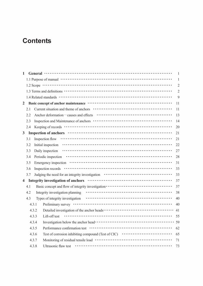
Contents 1 General ・・・・・・・・・・・・・・・・・・・・・・・・・・・・・・・・・・・・・・・・・・・・・・・・・・・・・・・・・・・・・・・・・・・・・・・ 1 1.1 Purpose of manual ・・・・・・・・・・・・・・・・・・・・・・・・・・・・・・・・・・・・・・・・・・・・・・・・・・・・・・・・・・・・・・ 1 1.2 Scope ・・・・・・・・・・・・・・・・・・・・・・・・・・・・・・・・・・・・・・・・・・・・・・・・・・・・・・・・・・・・・・・・・・・・・・・・ 2 1.3 Terms and denitions ・・・・・・・・・・・・・・・・・・・・・・・・・・・・・・・・・・・・・・・・・・・・・・・・・・・・・・・・・・・・ 2 1.4 Related standards ・・・・・・・・・・・・・・・・・・・・・・・・・・・・・・・・・・・・・・・・・・・・・・・・・・・・・・・・・・・・・・・ 9 2 Basic concept of anchor maintenance ・・・・・・・・・・・・・・・・・・・・・・・・・・・・・・・・・・・・・・・・・・・・・・・ 11 2.1 Current situation and theme of anchors ・・・・・・・・・・・・・・・・・・・・・・・・・・・・・・・・・・・・・・・・・・・・ 11 2.2 Anchor deformation-causes and effects ・・・・・・・・・・・・・・・・・・・・・・・・・・・・・・・・・・・・・・・・・・ 13 2.3 Inspection and Maintenance of anchors ・・・・・・・・・・・・・・・・・・・・・・・・・・・・・・・・・・・・・・・・・・・・ 14 2.4 Keeping of records ・・・・・・・・・・・・・・・・・・・・・・・・・・・・・・・・・・・・・・・・・・・・・・・・・・・・・・・・・・・・ 20 3 Inspection of anchors ・・・・・・・・・・・・・・・・・・・・・・・・・・・・・・・・・・・・・・・・・・・・・・・・・・・・・・・・・・ 21 3.1 Inspection ow ・・・・・・・・・・・・・・・・・・・・・・・・・・・・・・・・・・・・・・・・・・・・・・・・・・・・・・・・・・・・・・ 21 3.2 Initial inspection ・・・・・・・・・・・・・・・・・・・・・・・・・・・・・・・・・・・・・・・・・・・・・・・・・・・・・・・・・・・・・ 22 3.3 Daily inspection ・・・・・・・・・・・・・・・・・・・・・・・・・・・・・・・・・・・・・・・・・・・・・・・・・・・・・・・・・・・・・ 27 3.4 Periodic inspection ・・・・・・・・・・・・・・・・・・・・・・・・・・・・・・・・・・・・・・・・・・・・・・・・・・・・・・・・・・・ 28 3.5 Emergency inspection ・・・・・・・・・・・・・・・・・・・・・・・・・・・・・・・・・・・・・・・・・・・・・・・・・・・・・・・・・ 31 3.6 Inspection records ・・・・・・・・・・・・・・・・・・・・・・・・・・・・・・・・・・・・・・・・・・・・・・・・・・・・・・・・・・・・ 33 3.7 Judging the need for an integrity investigation ・・・・・・・・・・・・・・・・・・・・・・・・・・・・・・・・・・・・・・ 33 4 Integrity investigation of anchors ・・・・・・・・・・・・・・・・・・・・・・・・・・・・・・・・・・・・・・・・・・・・・・・ 37 4.1 Basic concept and ow of integrity investigation・・・・・・・・・・・・・・・・・・・・・・・・・・・・・・・・・・・・・ 37 4.2 Integrity investigation planning ・・・・・・・・・・・・・・・・・・・・・・・・・・・・・・・・・・・・・・・・・・・・・・・・ 38 4.3 Types of integrity investigation ・・・・・・・・・・・・・・・・・・・・・・・・・・・・・・・・・・・・・・・・・・・・・・・・ 40 4.3.1 Preliminary survey ・・・・・・・・・・・・・・・・・・・・・・・・・・・・・・・・・・・・・・・・・・・・・・・・・・・・・・・ 40 4.3.2 Detailed investigation of the anchor heads・・・・・・・・・・・・・・・・・・・・・・・・・・・・・・・・・・・・・・・ 41 4.3.3 Lift-off test ・・・・・・・・・・・・・・・・・・・・・・・・・・・・・・・・・・・・・・・・・・・・・・・・・・・・・・・・・・・・ 55 4.3.4 Investigation below the anchor head・・・・・・・・・・・・・・・・・・・・・・・・・・・・・・・・・・・・・・・・・・・・ 59 4.3.5 Performance conrmation test ・・・・・・・・・・・・・・・・・・・・・・・・・・・・・・・・・・・・・・・・・・・・・・ 62 4.3.6 Test of corrosion inhibiting compound (Test of CIC) ・・・・・・・・・・・・・・・・・・・・・・・・・・・・ 65 4.3.7 Monitoring of residual tensile load ・・・・・・・・・・・・・・・・・・・・・・・・・・・・・・・・・・・・・・・・・・・ 71 4.3.8 Ultrasonic aw test ・・・・・・・・・・・・・・・・・・・・・・・・・・・・・・・・・・・・・・・・・・・・・・・・・・・・・・ 73
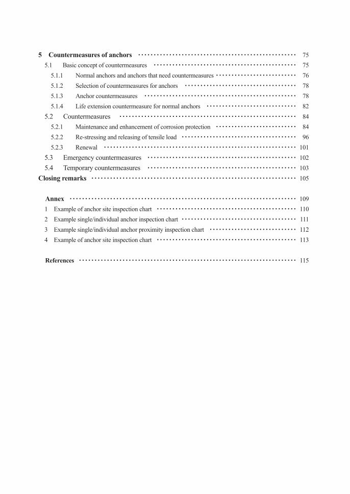
5 Countermeasures of anchors ・・・・・・・・・・・・・・・・・・・・・・・・・・・・・・・・・・・・・・・・・・・・・・・・・・・ 75 5.1 Basic concept of countermeasures ・・・・・・・・・・・・・・・・・・・・・・・・・・・・・・・・・・・・・・・・・・・・・・ 75 5.1.1 Normal anchors and anchors that need countermeasures ・・・・・・・・・・・・・・・・・・・・・・・・・・ 76 5.1.2 Selection of countermeasures for anchors ・・・・・・・・・・・・・・・・・・・・・・・・・・・・・・・・・・・・ 78 5.1.3 Anchor countermeasures ・・・・・・・・・・・・・・・・・・・・・・・・・・・・・・・・・・・・・・・・・・・・・・・・・ 78 5.1.4 Life extension countermeasure for normal anchors ・・・・・・・・・・・・・・・・・・・・・・・・・・・・・ 82 5.2 Countermeasures ・・・・・・・・・・・・・・・・・・・・・・・・・・・・・・・・・・・・・・・・・・・・・・・・・・・・・・・・・ 84 5.2.1 Maintenance and enhancement of corrosion protection ・・・・・・・・・・・・・・・・・・・・・・・・・・ 84 5.2.2 Re-stressing and releasing of tensile load ・・・・・・・・・・・・・・・・・・・・・・・・・・・・・・・・・・・・・ 96 5.2.3 Renewal ・・・・・・・・・・・・・・・・・・・・・・・・・・・・・・・・・・・・・・・・・・・・・・・・・・・・・・・・・・・・・・ 101 5.3 Emergency countermeasures ・・・・・・・・・・・・・・・・・・・・・・・・・・・・・・・・・・・・・・・・・・・・・・・・ 102 5.4 Temporary countermeasures ・・・・・・・・・・・・・・・・・・・・・・・・・・・・・・・・・・・・・・・・・・・・・・・・ 103 Closing remarks ・・・・・・・・・・・・・・・・・・・・・・・・・・・・・・・・・・・・・・・・・・・・・・・・・・・・・・・・・・・・・・・・・・ 105 Annex ・・・・・・・・・・・・・・・・・・・・・・・・・・・・・・・・・・・・・・・・・・・・・・・・・・・・・・・・・・・・・・・・・・・・・・・・・ 109 1 Example of anchor site inspection chart ・・・・・・・・・・・・・・・・・・・・・・・・・・・・・・・・・・・・・・・・・・・・・ 110 2 Example single/individual anchor inspection chart ・・・・・・・・・・・・・・・・・・・・・・・・・・・・・・・・・・・・・ 111 3 Example single/individual anchor proximity inspection chart ・・・・・・・・・・・・・・・・・・・・・・・・・・・・ 112 4 Example of anchor site inspection chart ・・・・・・・・・・・・・・・・・・・・・・・・・・・・・・・・・・・・・・・・・・・・・ 113 References ・・・・・・・・・・・・・・・・・・・・・・・・・・・・・・・・・・・・・・・・・・・・・・・・・・・・・・・・・・・・・・・・・・・・・・ 115
1 General
1.1 Purpose of manual
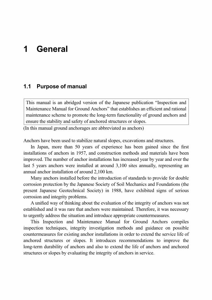
This manual is an abridged version of the Japanese publication “Inspection and Maintenance Manual for Ground Anchors” that establishes an efcient and rational maintenance scheme to promote the long-term functionality of ground anchors and ensure the stability and safety of anchored structures or slopes.
(In this manual ground anchorages are abbreviated as anchors) Anchors have been used to stabilize natural slopes, excavations and structures.
In Japan, more than 50 years of experience has been gained since the rst installations of anchors in 1957, and construction methods and materials have been improved. The number of anchor installations has increased year by year and over the last 5 years anchors were installed at around 3,100 sites annually, representing an annual anchor installation of around 2,100 km.
Many anchors installed before the introduction of standards to provide for double corrosion protection by the Japanese Society of Soil Mechanics and Foundations (the present Japanese Geotechnical Society) in 1988, have exhibited signs of serious corrosion and integrity problems.
A unied way of thinking about the evaluation of the integrity of anchors was not established and it was rare that anchors were maintained. Therefore, it was necessary to urgently address the situation and introduce appropriate countermeasures.
This Inspection and Maintenance Manual for Ground Anchors compiles inspection techniques, integrity investigation methods and guidance on possible countermeasures for existing anchor installations in order to extend the service life of anchored structures or slopes. It introduces recommendations to improve the long-term durability of anchors and also to extend the life of anchors and anchored structures or slopes by evaluating the integrity of anchors in service.
1 General 1
1.2 Scope
This manual is applicable to inspection, integrity investigation and countermeasures of anchors.
This manual is also applicable to new anchor installations and targets life cycle cost savings by considering inspection and maintenance in the design and installation of anchors. This manual is also applicable to temporary anchors.
This manual is aimed at the basic concept of inspection and maintenance of anchors and does not make recommendations for the maintenance of the anchored structures or slopes.
1.3 Terms and definitions
The terms and denitions used in this manual are as follows: - (1) Anchor: A system that transmits tensile load to the ground. An anchor
consists of a xed length, a free length and an anchor head. (2) Structure and/or slope: Objective stabilized by anchors. (3) Double corrosion protection: A double barrier of protection to provide
improved corrosion resistance. (4) Temporary anchor: An anchor installed for temporary support or
stabilization during a construction project. Temporary anchors are sometimes installed without, or with minimal, corrosion protection.
(5) Old type anchor: An anchor designed and installed prior to the establishment of the “Ground Anchor Design and Construction Standard”, designated by the Japan Geotechnical Society in November 1988 (JSF: D1-88).
(6) Fixed anchor length: Resistant component of the anchor formed by grouting the tendon to transmit the tensile load to the ground by shear or bearing resistance.
(7) Free anchor length: The length of tendon that transmits the tensile load from the anchor head to the xed length.
(8) Anchor head: The assembly that transmits the load from the supported structure or slope to the tendon and comprising bearing plate, locking unit and anchor cap.
Inspection Maintenance Manual for Ground anchors2
(9) Anchor below the bearing plate (or the anchor head): The part of the anchor immediately beneath the bearing plate.
(10) Tendon: The part of the anchor that transmits the tensile load from the anchor head to the grouted xed anchor.
(11) Protruding length for re-stressing: The excess length of tendon protruding at the anchor head that is required to enable re-stressing of the anchor.
(12) Free anchor length sheath: The exible plastic tube surrounding the tendon free length to prevent contact with the ground and provide corrosion protection.
(13) Grout: Setting material that transmits load from the tendon to the ground over the anchor xed length. The grout sometimes lls the anchor hole completely to provide additional corrosion protection. There are cement type and synthetic resin type grouts.
(14) Locking unit: The component for locking the tendon to the anchor head (15) Bearing plate: The component for transmitting the tensile load from the
locking unit to the anchored structure or slope. (16) Supporting structure: Plinth and/or other structure for effectively
distributing the tensile load from the anchor head to the structure or slope.
(17) Anchor cap: A cover providing mechanical and corrosion protection to the anchor locking unit and protruding tendon. The anchor cap is lled with a corrosion-inhibiting compound and can be removed during maintenance.
(18) Concrete cover: Concrete or mortar covering the locking unit to provide mechanical and corrosion protection.
(19) Corrosion protection materials: Materials that protect the steel tendon against corrosion
(20) Corrosion inhibiting compound (CIC): Corrosion protection compound such as grease or petrolatum.
(21) Inspection: A daily, periodic or emergency in situ physical or visual investigation to check the condition of an anchor.
(22) Preliminary survey: A pre-inspection collection and examination of reference data, drawings, specications and maintenance records.
(23) Initial inspection: An inspection conducted to understand the overall situation of the anchor and structure or slope to identify anchors that could possibly be suffering from an integrity problem and require further inspection.
(24) Visual inspection: Inspection of the appearance of anchors and surrounding area, structure or slope to detect presence of any abnormalities. In
1 General 3
daily and emergency inspections the structure and/or slope are checked from within a patrol car. During periodic inspections each anchor is checked carefully at close proximity.
(25) Proximity inspection: An inspection at close range to investigate any abnormalities that are difcult to conrm by visual inspection from afar at the time of a patrol. In some cases physical checks such as the hammering test are conducted.
(26) Daily inspection: Mainly a visual inspection conducted daily, during regular patrols.
(27) Periodic inspection: An inspection conducted every six months or annually. This is a more detailed inspection compared to the daily inspection and occurs when signs of abnormality are detected during daily or emergency inspections.
(28) Emergency inspection: An emergency inspection is conducted by visual inspection when deemed necessary but mainly after the occurrence of natural events such as torrential rain or signicant earthquakes.
(29) Integrity investigation: When an abnormality is identied the anchor condition is conrmed in detail and its integrity is evaluated.
(30) Countermeasure: Remedial work undertaken to enhance durability or performance, extend service life, repair or replace an anchor, including remedial work undertaken in an emergency.
(31) Countermeasure for durability enhancement: Remedial work undertaken to ensure that the integrity of the anchor is maintained during its designed service life.
(32) Repair and reinforcement: If, after an integrity investigation, the performance of an anchor is less than the level required for service, countermeasures are taken in order to improve performance to meet or exceed service requirements.
(33) Renewal: If the performance of the anchor cannot be improved to meet the service requirements through repair or reinforcement, or it is not economic to do so, an anchor is renewed.
(34) Emergency countermeasure: An emergency countermeasure is taken for anchors performing below the service limit level, or predicted to fall below the service limit level, in order to prevent damage to third parties.
(35) Temporary countermeasure: If, after an integrity investigation, an anchor is found to be below the level required for service, a temporary countermeasure can be taken in order to maintain temporary function of the anchor and prevent further deterioration in this short
Inspection Maintenance Manual for Ground anchors4
time. (36) Countermeasure for life extension: A countermeasure taken to extend the
service life of an anchor as an alternative to renewal. (37) Lift-off test: A procedure to measure the residual load of an anchor. A jack
is attached the locking unit and to the protruding length of the tendon and the tensile load / displacement properties are used to investigate residual load by lifting the anchor head off the bearing plate.
(38) Anchor performance conrmation test: A test of the anchor to conrm that the strength of the tendon, the pull-out load of the anchor and the restraining force provided by the anchor are all above the design criteria.
(39) Ultrasonic inspection: An inspection technique using ultrasound to detect damage to the tendon and used as a preliminary investigation to assess safety.
(40) Monitoring: Continuous or high frequency inspection of an anchor during its service life. Generally, the residual tensile load is monitored by load cell.
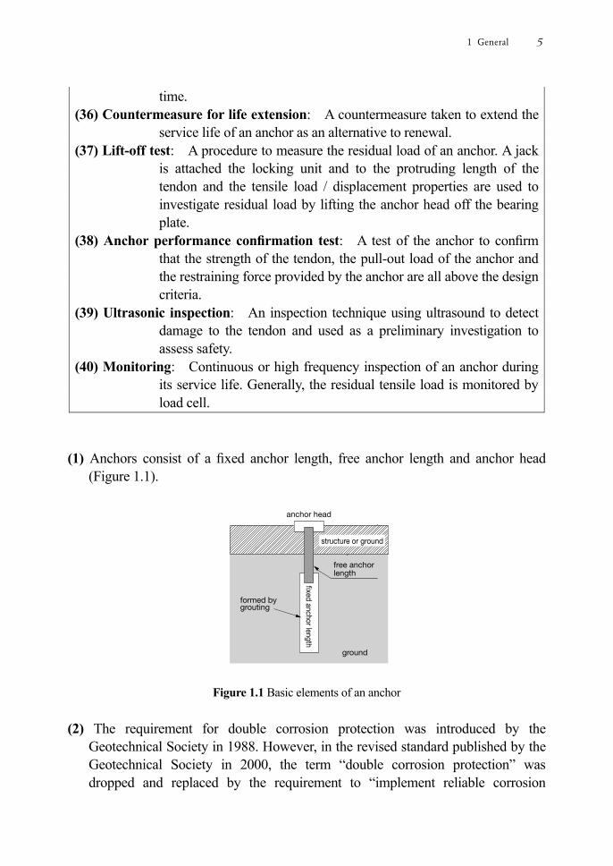
(1) Anchors consist of a xed anchor length, free anchor length and anchor head
(Figure 1.1).
Figure 1.1 Basic elements of an anchor
(2) The requirement for double corrosion protection was introduced by the
Geotechnical Society in 1988. However, in the revised standard published by the Geotechnical Society in 2000, the term “double corrosion protection” was dropped and replaced by the requirement to “implement reliable corrosion
1 General 5
protection to prevent deterioration of anchors during their service life”. (3) Before 1988, the “Ground Anchor Design and Construction Standard” did not
specify the need for double corrosion protection. Therefore, reliable corrosion protection was not implemented for many anchors, resulting in durability problems after construction. In this manual, these anchors are dened as “old type anchors”, distinguishing them from anchors installed with reliable corrosion protection.
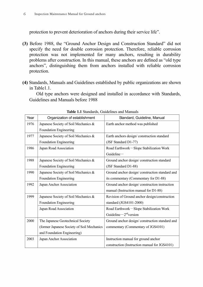
(4) Standards, Manuals and Guidelines established by public organizations are shown
in Table1.1. Old type anchors were designed and installed in accordance with Standards,
Guidelines and Manuals before 1988
Table 1.1 Standards, Guidelines and Manuals Year Organization of establishment Standard, Guideline, Manual 1976 Japanese Society of Soil Mechanics &
Foundation Engineering Earth anchor method was published
1977 Japanese Society of Soil Mechanics & Foundation Engineering
Earth anchors design/ construction standard (JSF Standard D1-77)
1986 Japan Road Association Road Earthwork-Slope Stabilization Work Guideline-
1988
Japanese Society of Soil Mechanics & Foundation Engineering
Ground anchor design/ construction standard (JSF Standard D1-88)
1990 Japanese Society of Soil Mechanics & Foundation Engineering
Ground anchor design/ construction standard and its commentary (Commentary for D1-88)
1992 Japan Anchor Association Ground anchor design/ construction instruction manual (Instruction manual for D1-88)
1999 Japanese Society of Soil Mechanics & Foundation Engineering
Revision of Ground anchor design/construction standard (JGS4101-2000)
Japan Road Association Road Earthwork-Slope Stabilization Work Guideline-2ndversion
2000 The Japanese Geotechnical Society (former Japanese Society of Soil Mechanics and Foundation Engineering)
Ground anchor design/ construction standard and commentary (Commentary of JGS4101)
2003 Japan Anchor Association Instruction manual for ground anchor construction (Instruction manual for JGS4101)
Inspection Maintenance Manual for Ground anchors6
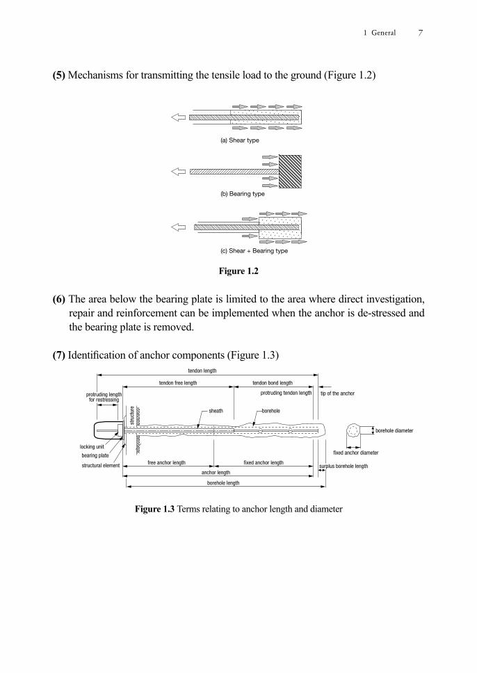
(5) Mechanisms for transmitting the tensile load to the ground (Figure 1.2)
Figure 1.2
(6) The area below the bearing plate is limited to the area where direct investigation,
repair and reinforcement can be implemented when the anchor is de-stressed and the bearing plate is removed.
(7) Identication of anchor components (Figure 1.3)
Figure 1.3 Terms relating to anchor length and diameter
1 General 7
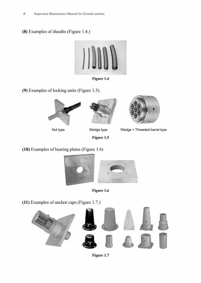
(8) Examples of sheaths (Figure 1.4.)
Figure 1.4
(9) Examples of locking units (Figure 1.5).
Figure 1.5 (10) Examples of bearing plates (Figure 1.6)
Figure 1.6
(11) Examples of anchor caps (Figure 1.7.)
Figure 1.7
Nut type Wedge type Wedge + Threaded barrel type
Inspection Maintenance Manual for Ground anchors8
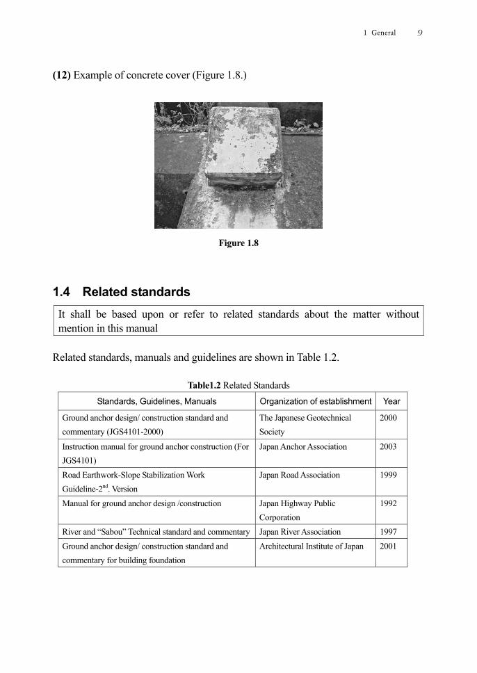
(12) Example of concrete cover (Figure 1.8.)
Figure 1.8
1.4 Related standards
It shall be based upon or refer to related standards about the matter without mention in this manual
Related standards, manuals and guidelines are shown in Table 1.2.
Table1.2 Related Standards
Standards, Guidelines, Manuals Organization of establishment Year
Ground anchor design/ construction standard and commentary (JGS4101-2000)
The Japanese Geotechnical Society
2000
Instruction manual for ground anchor construction (For JGS4101)
Japan Anchor Association 2003
Road Earthwork-Slope Stabilization Work Guideline-2nd. Version
Japan Road Association
1999
Manual for ground anchor design /construction Japan Highway Public Corporation
1992
River and “Sabou” Technical standard and commentary Japan River Association 1997 Ground anchor design/ construction standard and commentary for building foundation
Architectural Institute of Japan 2001
1 General 9

Inspection Maintenance Manual for Ground anchors2
2 Basic concept of anchor maintenance
2.1 Current situation and theme of anchors
There are many thousands of anchored structures or slopes in Japan. However, some of the anchors exhibit durability problems and some are performing below the level expected at the time of design and installation.
Preservation of anchor function should be achieved by conducting appropriate maintenance in order to prevent failure of anchored structures or slopes and consequent damage to third parties.
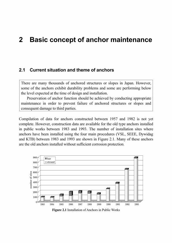
Compilation of data for anchors constructed between 1957 and 1982 is not yet complete. However, construction data are available for the old type anchors installed in public works between 1983 and 1993. The number of installation sites where anchors have been installed using the four main procedures (VSL, SEEE, Dywidag and KTB) between 1983 and 1993 are shown in Figure 2.1. Many of these anchors are the old anchors installed without sufcient corrosion protection.
Figure 2.1 Installation of Anchors in Public Works
2 Basic concept of anchor maintenance 11
Evidence of problems related to durability and function, such as deformation and damage, can be seen in many anchors that have been in service for a long period, particularly in the old type anchors.
The main problems that can be observed at the anchor sites are as follows: -
① Deformation of anchor heads Signicant movement of an anchor head can indicate that the tendon has fractured, in which case the anchor may have partially pulled out, subsidence of the supporting structure may have occurred and the anchor head itself may have lifted by a few centimetres or pulled out by as much as a few metres.
② Damage to concrete cover Where a concrete cover has been installed, deterioration such as cracking, spalling and breaking of the concrete cover can occur leading to third party damage.
③ Deformation around anchor head Indications of movement or deformation of anchors may be observed around the anchor head.
For example, if rain or ground water has permeated into the anchor, traces of isolated lime or an abundance of plant growth may be observed around the anchor head. Also, leakage of corrosion inhibiting compound from the anchor head can indicate movement or deformation.
④ Deterioration and deformation of anchor supporting structure Deformation can occur in anchored slopes as a result of deterioration of anchor supporting structures such as steel or concrete beams. Such deformations of slopes can occur without any corresponding deformation of the anchor.
Structures or slopes are stabilized by anchors each having a high tensile strength,
typically up to several hundred kN, but even higher in some instances. However, if anchors lose function, there is a possibility of land slippage or falling debris from rocks or failure of the supporting structure or anchor heads themselves. In such cases third party damage could occur. In order to prevent such accidents the condition of anchors should be conrmed by daily inspection, and when any problem related to integrity is observed, necessary systems or procedures for implementing countermeasures should be prepared.
The functionality of anchors should be maintained at, or above, the required standard throughout their service life and their integrity should always be conrmed. In case that there is a possibility that the necessary function cannot be maintained, countermeasures for enhancement of function and durability should be undertaken.
Inspection Maintenance Manual for Ground anchors12
2.2 Anchor deformation - causes and effects
1) Any movement or deterioration of the anchor should be detected as early as possible and the possible causes and effects should be determined
2) An effective countermeasure should be determined after due consideration of possible causes and effects
(1) The primary objective of inspection and maintenance of anchors is to prevent the
failure of anchored structures or slopes that could lead to damage or injury to property or persons. Therefore, any abnormality or deformation should be detected as early as possible during inspection and maintenance and the possible causes and effects should be understood.
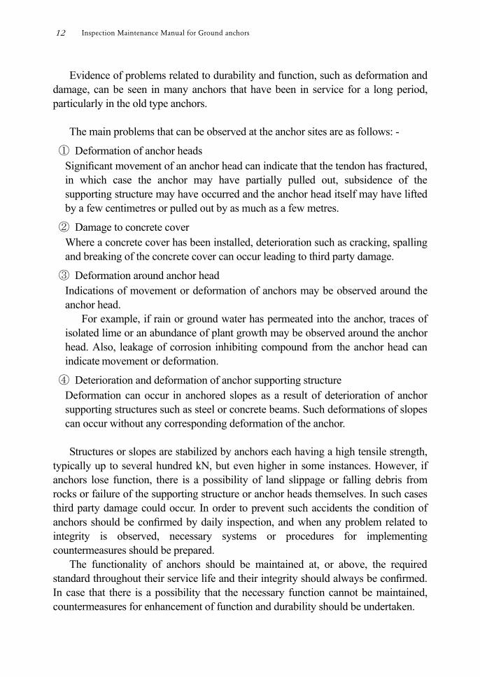
(2) The causes and effects illustrated in Figure 2.2 are not usually directly related to
abnormalities or deformations identied during inspection and maintenance.
Figure 2.2 Causes and effects of anchor deterioration and deformation
2 Basic concept of anchor maintenance 13
However, by considering causes and effects it may be possible to predict the nal potential outcome of an abnormality or deformation and determine an effective countermeasure such as repair or reinforcement.
2.3 Inspection and Maintenance of anchors
1) Maintenance of anchors comprising inspection, integrity investigation and countermeasures, should be implemented based on this manual in order to keep the performance of the anchors at the required level during their service life and also to extend their service life as far as possible.
2) For newly installed anchors, excluding temporary anchors, all design data and installation records shall be collated and form the reference data for inspection and maintenance planning and implementation.
3) Prior to inspection and maintenance of anchors a preliminary survey comprising collection and examination of reference data and review of peripheral conditions shall be conducted.
4) The frequency and extent of inspection and integrity investigation of anchors shall be determined based upon conditions specic to the anchor location including purpose, importance of anchors, and local conditions.
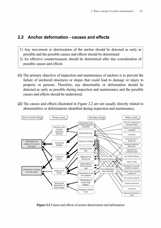
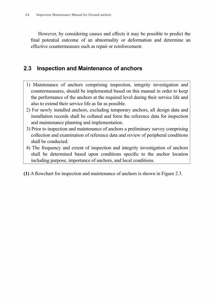
(1) A owchart for inspection and maintenance of anchors is shown in Figure 2.3.
Inspection Maintenance Manual for Ground anchors14
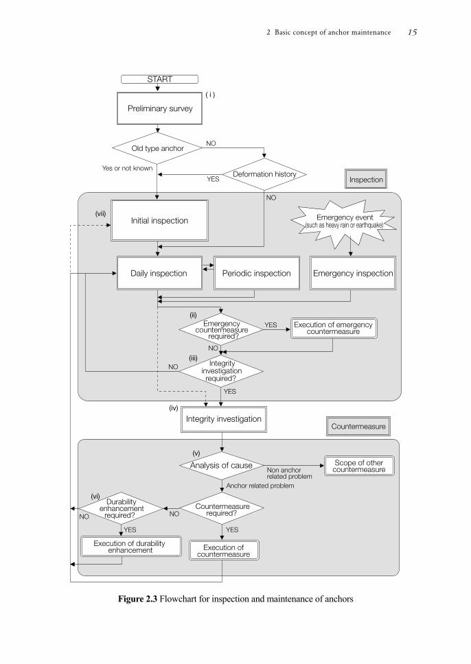
Figure 2.3 Flowchart for inspection and maintenance of anchors
2 Basic concept of anchor maintenance 15
Footnotes relating to Figure 2.3 (i) Preliminary survey
The objective of the preliminary survey is to collect all necessary data and information relevant to the inspection and maintenance of the anchor.
Engineering drawings for the design of the anchor, anchor supporting structure and anchored structure or slope, inspection and maintenance records and details of the surrounding topography shall be collected.
(ii) Requirement for emergency countermeasures
An emergency countermeasure is judged necessary if it will prevent damage to third parties, including human life or property.
An emergency countermeasure should be conducted immediately upon the discovery (during inspection or maintenance) of an abnormality in the anchor or anchored structure or slope that presents such a threat.
(iii) Requirement for integrity investigation
The decision to conduct an anchor integrity investigation shall be based on the results of daily, periodic or emergency inspections as illustrated in Figure 2.3.
If there is a high possibility of an integrity problem or a deformation is found in the anchored structures or slopes and the cause cannot be identied by inspection, a detailed integrity investigation should be conducted.
If it is still not possible to fully conrm the condition of the anchor, regular integrity investigations will be necessary.
(iv) Integrity investigation
An integrity investigation includes the following investigations and tests (refer to Chapter 4 for detailed content and procedures).
① Preliminary survey The information collected during the preliminary survey (specication, engineering details, site conditions, installation and maintenance records, details of surrounding topography) is reviewed in order to plan the integrity investigation.
② Detailed investigation of anchor head A detailed investigation of the anchor head is conducted in order to identify any abnormalities and to conrm the necessity and appropriateness of an integrity investigation.
It helps to conrm the condition of abnormalities detected by overall visual inspection or hammering test whereby the anchor head is simply hit and the
Inspection Maintenance Manual for Ground anchors16
sound is judged by ear. The detailed investigation of the anchor head involves a visual inspection
of any abnormality such as damage, cracks or deterioration of the concrete and anchor cap, corrosion of tendon and locking unit, presence of groundwater, leakage and condition of corrosion inhibiting compound, and conrmation of the protruding length of tendon in order to assess the possibility of releasing and re-stressing the anchor.
③ Lift-off test The residual tensile load of the anchor is conrmed by lift-off test.
From the relationship between load and displacement, the apparent free anchor length and anchor integrity can be conrmed and the possibility of releasing and re-stressing the anchor in order to conduct an investigation below the anchor head can be assessed.
④ Investigation below the anchor head In order to evaluate the integrity of an anchor below the head, the anchor is de-stressed and the locking unit and bearing plate removed.
The tendon is examined for corrosion, the level and condition of corrosion inhibiting compound checked and any ingress of groundwater or damage to the sheath investigated.
⑤ Anchor performance conrmation test The anchor performance conrmation test conrms the tensile strength of the tendon, the anchor lock-off load and the apparent tendon free length from the load vs. displacement relationship.
⑥ Evaluation of corrosion inhibiting compound The corrosion inhibiting compound in the anchor head and below the bearing plate is examined for deterioration e.g. oxidation or property change.
If deemed necessary, the corrosion inhibiting compound is changed or a sample is taken to test its effectiveness.
⑦ Monitoring The change in residual tensile load over time can be monitored by the installation of a load cell at the anchor head.
The obtained data is analyzed in order to judge the integrity of the anchor and predict future trends, including the necessity for additional investigation.
⑧ Ultrasonic test for detecting damage An ultrasound test is used to detect damage to the tendon and assess re-stressing.
2 Basic concept of anchor maintenance 17
Other investigations include the following inspections of anchored structures or slopes and the surrounding environment.
① Ground and groundwater assessment Chemical properties of ground and groundwater at the anchor location should be tested to check for any corrosive effects on the anchor.
Geothermal heat and stray electric currents shall be investigated.
② Investigation of anchor supporting structure Localized and overall displacement of the anchor supporting structure and movement of the structure and peripheral ground shall also be investigated and considered when determining appropriate countermeasures for anchors.
(v) Requirement for countermeasures
If the integrity investigation shows there is a problem with the anchor, an appropriate countermeasure should be undertaken in accordance with the recommendations of Chapter 5.
For anchors that are performing below the required performance level, or for anchors where performance is deteriorating, countermeasures should be taken to restore and maintain performance to the required level for the remainder of their service life.
Although integrity investigations are performed on individual anchors, it may be appropriate to group a number of anchors together and implement common countermeasures to the anchors.
Anchors that are taken out of service should be de-stressed and covered if necessary to ensure they do not present a danger in the future.
(vi) Requirement for durability enhancement Even if the integrity investigation shows that repair or enforcement is not required, it may be prudent to implement a countermeasure to enhance the durability of an anchor and thereby minimize the need for further countermeasures in the future.
(vii) Following the execution of countermeasures or durability enhancement to
anchors, an initial inspection shall then be conducted and the modied condition of the anchor shall be recorded.
(2) Inspections shall be conducted regularly and systematically at a pre-determined
frequency. Guidelines on frequency of inspection and integrity investigation for anchors
are provided in Table 2.1.
Inspection Maintenance Manual for Ground anchors18
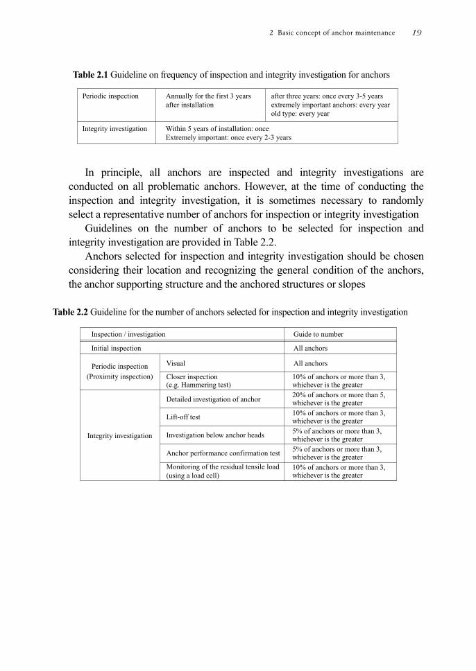
Table 2.1 Guideline on frequency of inspection and integrity investigation for anchors
In principle, all anchors are inspected and integrity investigations are conducted on all problematic anchors. However, at the time of conducting the inspection and integrity investigation, it is sometimes necessary to randomly select a representative number of anchors for inspection or integrity investigation
Guidelines on the number of anchors to be selected for inspection and integrity investigation are provided in Table 2.2.
Anchors selected for inspection and integrity investigation should be chosen considering their location and recognizing the general condition of the anchors, the anchor supporting structure and the anchored structures or slopes
Table 2.2 Guideline for the number of anchors selected for inspection and integrity investigation
2 Basic concept of anchor maintenance 19
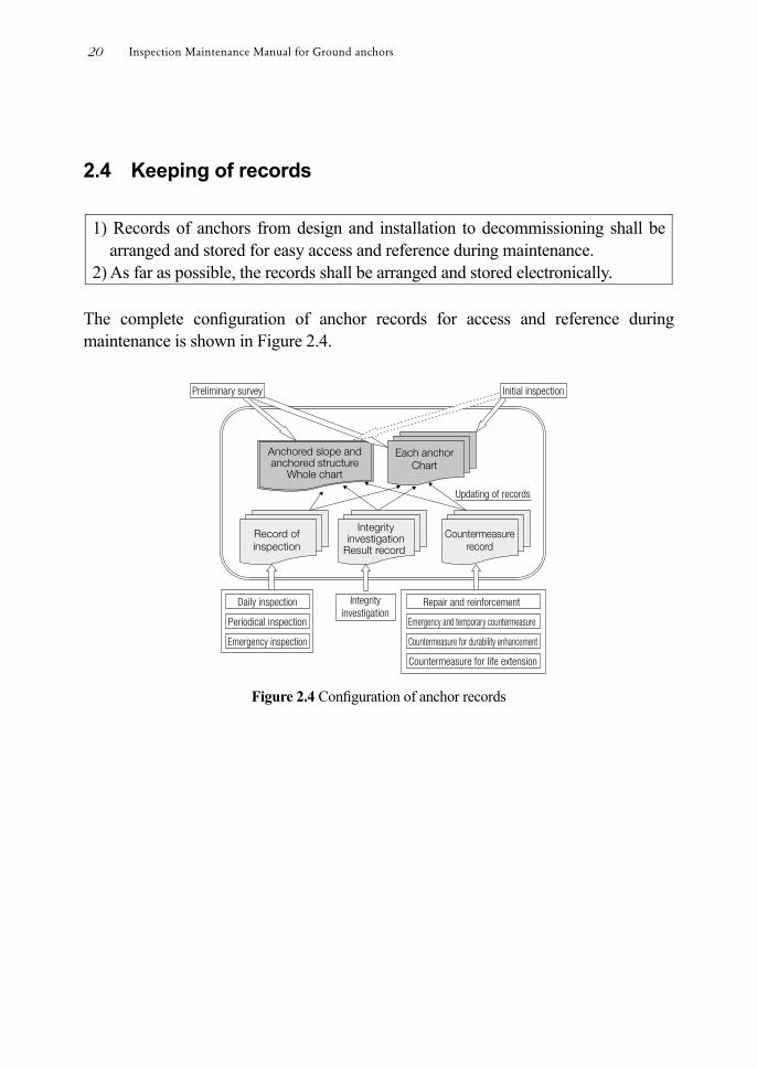
2.4 Keeping of records
1) Records of anchors from design and installation to decommissioning shall be arranged and stored for easy access and reference during maintenance.
2) As far as possible, the records shall be arranged and stored electronically. The complete conguration of anchor records for access and reference during maintenance is shown in Figure 2.4.
Figure 2.4 Conguration of anchor records
Inspection Maintenance Manual for Ground anchors20
3 Inspection of anchors
3.1 Inspection flow
1) Anchor inspections consist of daily, periodic and emergency inspections. 2) Initial inspections of anchors, anchored structures or slopes should be conducted
if there are any reliability concerns or if possible problems are identied in the preliminary survey.
3) The frequency, scope and inspection procedures are determined based on the results of the initial inspection and the importance of anchored structures or slopes. When determining the importance of anchored structures or slopes the consequence of movement or failure should be considered.
4) Under normal circumstances daily and periodic inspections are conducted as scheduled.
5) Emergency inspections should be conducted whenever deemed necessary, but usually after the occurrence of natural events such as torrential rain or signicant earthquakes.
6) The results of inspections should be recorded and stored for future reference. (1) As shown in Figure 2-3, anchor inspections are categorized as initial inspection,
daily inspection, periodic inspection or emergency inspection. A further category is the integrity investigation.
(2) Guidance on interpreting the results of an initial inspection and determining if an
integrity investigation is necessary can be found at section 3.6. If an initial inspection does indicate that there is a high possibility of an
integrity problem, a detailed investigation and evaluation of integrity should be conducted by integrity investigation. After conducting the integrity investigation and implementing necessary countermeasures, future inspection requirements are determined and scheduled.
3 Inspection of anchors 21
(3) If an anchor integrity problem is identied in the initial inspection, depending on the nature of the problem and/or circumstances relating to the anchored structure or slope, the anchor is prioritized for future further inspections or countermeasures.
3.2 Initial inspection
1) Initial inspections should generally be conducted for all old type anchors and for anchors, or anchored structures or slopes with a history of failure.
2) An initial inspection should include a review of all available information on the anchor, the anchored slope, and anchored structure, including specications and previous inspection reports on the condition of the anchor, anchor head, bearing plate, and anchored slope or structure.
3) It is recommended that initial inspections are conducted for all anchors 4) If an initial inspection indicates there to be a high possibility of an integrity
problem, an integrity investigation should be conducted. 5) Anchor details gathered during preliminary surveys and inspections should be
recorded and stored in the investigation notebook and should be available and referred to during future inspections.
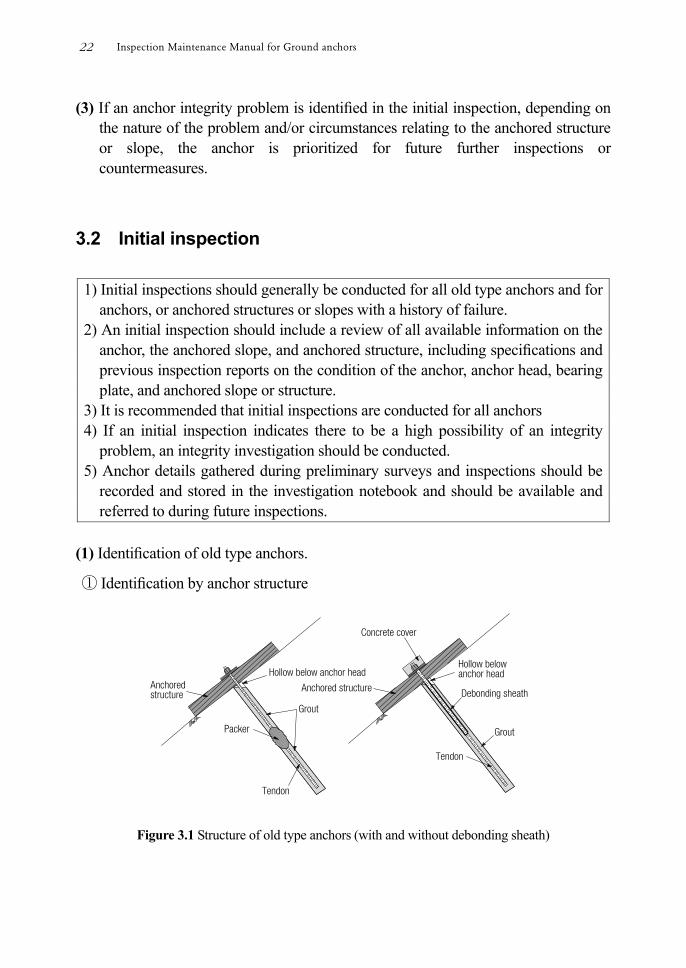
(1) Identication of old type anchors.
① Identication by anchor structure
Figure 3.1 Structure of old type anchors (with and without debonding sheath)
Inspection Maintenance Manual for Ground anchors22
② Identication by year of design and construction Double corrosion protection was introduced by Ground Anchor Design / Construction Standard (JSF:D1-88) (1988)
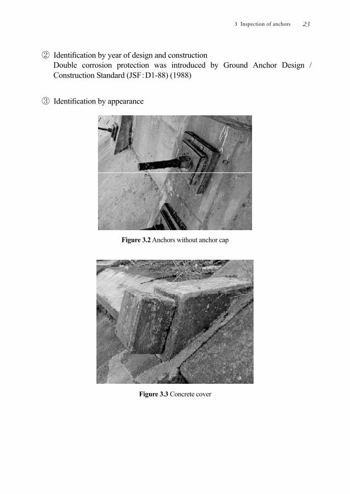
③ Identication by appearance
Figure 3.2 Anchors without anchor cap
Figure 3.3 Concrete cover
3 Inspection of anchors 23
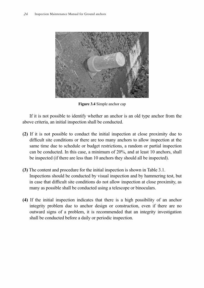
Figure 3.4 Simple anchor cap
If it is not possible to identify whether an anchor is an old type anchor from the
above criteria, an initial inspection shall be conducted. (2) If it is not possible to conduct the initial inspection at close proximity due to
difcult site conditions or there are too many anchors to allow inspection at the same time due to schedule or budget restrictions, a random or partial inspection can be conducted. In this case, a minimum of 20%, and at least 10 anchors, shall be inspected (if there are less than 10 anchors they should all be inspected).
(3) The content and procedure for the initial inspection is shown in Table 3.1.
Inspections should be conducted by visual inspection and by hammering test, but in case that difcult site conditions do not allow inspection at close proximity, as many as possible shall be conducted using a telescope or binoculars.
(4) If the initial inspection indicates that there is a high possibility of an anchor
integrity problem due to anchor design or construction, even if there are no outward signs of a problem, it is recommended that an integrity investigation shall be conducted before a daily or periodic inspection.
Inspection Maintenance Manual for Ground anchors24
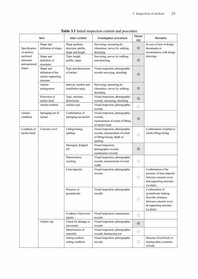
Table 3.1 Initial inspection content and procedure
Item Main content Investigation procedure Neces
sity Remarks
Specication of anchors, anchored structures and anchored slopes
Shape and denition of slopes
Slope gradient, direction, prole, shape and height
Surveying, measuring by clinometer, survey by walking, sketching
㉧
In case of lack of design documents or inconsistency with design drawings
Shape and denition of structures
Type, height, prole, shape
Surveying, survey by walking and sketching ㉧
Shape and denition of the anchor supporting structure
Type and dimensions of anchor
Visual inspection, photographic records surveying, sketching ㉧
Anchor arrangement
Interval, number and installation angle
Surveying, measuring by clinometer, survey by walking, sketching.
㉧
Protection of anchor head
Type, structure, dimensions
Visual inspection, photographic records, measuring, sketching
㉧
Anchor method Anchor type Visual inspection, photographic records
〇
Anchor condition
Springing-out of anchor
Conrmation of springing-out anchor
Visual inspection, photographic records, measurement of extent of lifting of anchor head
㉧
Condition of anchor head
Concrete cover Lifting/raising, spalling
Visual inspection, photographic records, measurement of extent of lifting/raising, depth of spalling
〇
Conrmation of partial or whole lifting/raising
Damaged, dropped off
Visual inspection, photographic records, maintenance records
㉧
Deterioration, cracking
Visual inspection, photographic records, measurement of crack width
〇
Lime deposits Visual inspection, photographic records
〇
Conrmation of the presence of lime deposits between concrete cover and supporting structure (or plate)
Presence of groundwater
Visual inspection, photographic records
〇
Conrmation of groundwater leaking from the clearance between concrete cover & supporting structure (or plate)
Evidence of previous repairs
Visual inspection, maintenance records
〇
Anchor cap Check for damage or movement
Visual inspection, photographic records
㉧
Deterioration of materials
Visual inspection, photographic records, hammering test
〇
Setting method, setting condition
Visual inspection, photographic records 〇
Structure xed rmly to bearing plate, existence of bolts
3 Inspection of anchors 25

Presence of groundwater
Visual inspection, photographic records
〇
Item Main content Investigation procedure
Necessity Rema
rks Item
Condition of anchor head
Anchor cap Evidence of previous repairs
Visual inspection, photographic records, maintenance records
〇
Corrosion inhibiting compound
Leakage Visual inspection, photographic records ㉧
Presence of dirt around head cap
Bearing plate Lifting/raising Visual inspection, photographic records, hammering test
〇 Partial or whole
Presence of groundwater
Visual inspection, photographic records
〇
Conrmation of groundwater from the clearance between bearing plate and supporting structure (or plate)
Bearing plate, supporting structure
Movement or subsidence
Opening or slippage of joints
Visual inspection, photographic records, surveying, sketching,
〇
Deterioration of concrete
Visual inspection, photographic records
〇
Lime deposits Visual inspection, photographic records
〇
Damaged or dropped off
Visual inspection, photographic records, maintenance records
㉧
Fissure, crack Visual inspection, photographic records, crack width measurement
〇
Lifting or movement away from supported slope or rock face
Visual inspection, photographic records, measurement of extent of lifting/raising
〇
Evidence of previous repairs
Visual inspection, photographic records, maintenance records
〇
Others Groundwater Quantity and place of groundwater
Visual inspection, photographic records, quantity of groundwater, sketching
〇
Surrounding situation
Possibility of stray current
Surrounding survey 〇
Deformation of whole mountain
Extent of deformation, subsidence and cracking of crest or slopes
Visual inspection, photographic records, surveying, sketching, measurement by inclinometer or extensometer and measurement of crack widths
㉧
Any data obtained during the inspection should be stored for future reference
Deformation of surrounding structures
Subsidence, deformation ㉧
Notes: ㉧ Crucial items required for future inspections and integrity investigations
◯ Desirable items. However, it is not always possible to conrm every item if access is difcult.
Inspection Maintenance Manual for Ground anchors26

3.3 Daily inspection
1) Daily inspections should be conducted for all anchors. 2) Daily inspections are conducted by visual inspection to check for any
abnormalities in the anchors, anchor heads and anchor supporting structures. 3) The frequency of an inspection patrol will depend on the importance of the
facility. 4) If an abnormality is found in the anchor, anchored structure or slope during a
daily inspection, the integrity of the anchor should be judged. If it is judged that there is an anchor integrity problem, the need to implement an immediate countermeasure should be assessed considering stability, importance of the anchored structure or slope, and possibility of damage to third parties. The need for an integrity investigation, repair or reinforcement work should also be assessed.
5) Records of daily inspection results shall be kept. (1) If an abnormality cannot be assessed from the results of the daily inspection, the
anchor should undergo a periodic inspection. (2) Items for consideration and examination during a daily inspection are shown in
Table 3.2. Items that can be inspected by visual inspection are inspection items and are
mainly aimed at conrming abnormalities. If continuous monitoring equipment is installed to measure the tensile load of
anchors or deformation of anchored structures or slopes, the measured data shall be reviewed to conrm abnormalities.
3 Inspection of anchors 27

Table 3.2 Daily inspection items
Item Main content Necessity Remarks
Anchor condition
Springing -out of anchor
Conrmation of a sprung anchor ㉧
Conrmation by visual inspection
Anchor tensile load △
Condition of anchor head
Condition of concrete cover
Damaged or dropped away ㉧
Anchor cap Check for damage or movement ㉧
Supporting structure
Damaged or dropped off ㉧
Other
Deformation of slope & surrounding areas
Extent of deformation or subsidence △
Deformation of the surrounding structure
Subsidence、deformation △
Notes: ㉧ Items considered essential for judging integrity △ Inspection is possible if continuous monitoring equipment is installed
3.4 Periodic inspection
1) Periodic inspections are more detailed than daily inspections and should be conducted at an appropriate frequency.
2) Periodic inspections shall be generally conducted by visual inspection and, if access allows close proximity inspection, will include a hammering test and measurements.
3) In general, periodic visual inspection of all anchors should be conducted. 4) The integrity of an anchor, anchored structures or slopes is judged based on the
results of the inspection. If there is judged to be an anchor integrity problem, the need for an immediate countermeasure should be assessed considering stability, importance of the anchored structures or slopes, and possibility of damage to third parties. The need for an integrity investigation, repair or reinforcement work should be assessed.
5) Records of periodic inspection results should be kept. (1) A periodic inspection shall be a visual inspection conducted on foot every 6
months to 1 year for all anchors.
Inspection Maintenance Manual for Ground anchors28
Guidelines on the frequency and number of anchors that shall be selected for periodic inspection are provided in Tables 2.1 and 2.2.
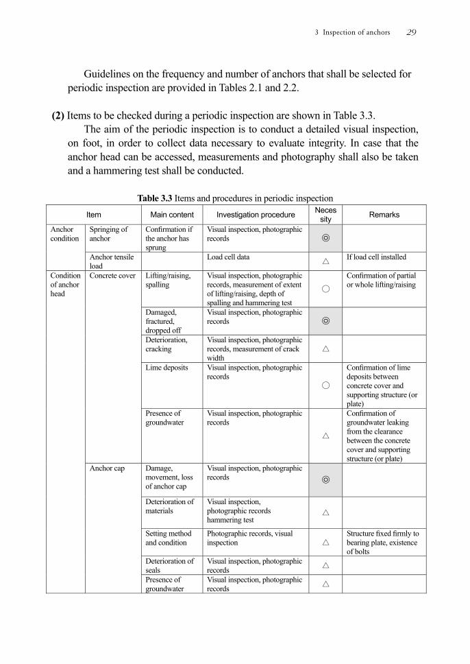
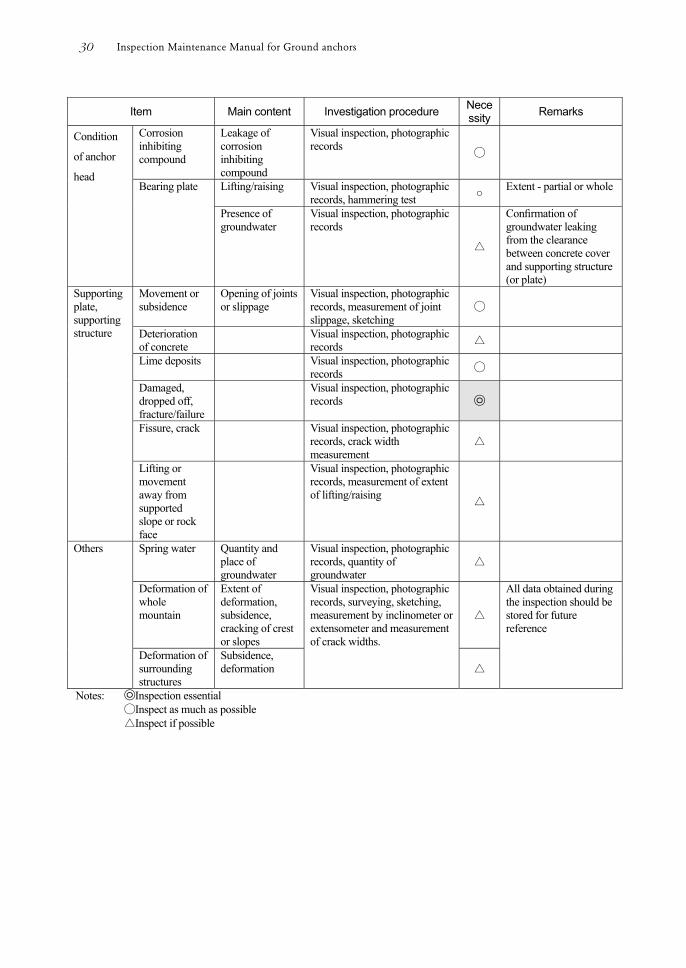
(2) Items to be checked during a periodic inspection are shown in Table 3.3.
The aim of the periodic inspection is to conduct a detailed visual inspection, on foot, in order to collect data necessary to evaluate integrity. In case that the anchor head can be accessed, measurements and photography shall also be taken and a hammering test shall be conducted.
Table 3.3 Items and procedures in periodic inspection
Item Main content Investigation procedure Necessity Remarks
Anchor condition
Springing of anchor
Conrmation if the anchor has sprung
Visual inspection, photographic records ㉧
Anchor tensile load
Load cell data △ If load cell installed
Condition of anchor head
Concrete cover Lifting/raising, spalling
Visual inspection, photographic records, measurement of extent of lifting/raising, depth of spalling and hammering test
◯
Conrmation of partial or whole lifting/raising
Damaged, fractured, dropped off
Visual inspection, photographic records ㉧
Deterioration, cracking
Visual inspection, photographic records, measurement of crack width
△
Lime deposits
Visual inspection, photographic records
◯
Conrmation of lime deposits between concrete cover and supporting structure (or plate)
Presence of groundwater
Visual inspection, photographic records
△
Conrmation of groundwater leaking from the clearance between the concrete cover and supporting structure (or plate)
Anchor cap Damage, movement, loss of anchor cap
Visual inspection, photographic records ㉧
Deterioration of materials
Visual inspection, photographic records hammering test
△
Setting method and condition
Photographic records, visual inspection
△ Structure xed rmly to bearing plate, existence of bolts
Deterioration of seals
Visual inspection, photographic records △
Presence of groundwater
Visual inspection, photographic records △
3 Inspection of anchors 29
Item Main content Investigation procedure Necessity Remarks
Condition
of anchor
head
Corrosion inhibiting compound
Leakage of corrosion inhibiting compound
Visual inspection, photographic records
◯
Bearing plate Lifting/raising Visual inspection, photographic records, hammering test ○ Extent - partial or whole
Presence of groundwater
Visual inspection, photographic records
△
Conrmation of groundwater leaking from the clearance between concrete cover and supporting structure (or plate)
Supporting plate, supporting structure
Movement or subsidence
Opening of joints or slippage
Visual inspection, photographic records, measurement of joint slippage, sketching
◯
Deterioration of concrete
Visual inspection, photographic records △
Lime deposits Visual inspection, photographic records ◯
Damaged, dropped off, fracture/failure
Visual inspection, photographic records ㉧
Fissure, crack Visual inspection, photographic records, crack width measurement
△
Lifting or movement away from supported slope or rock face
Visual inspection, photographic records, measurement of extent of lifting/raising
△
Others Spring water Quantity and place of groundwater
Visual inspection, photographic records, quantity of groundwater
△
Deformation of whole mountain
Extent of deformation, subsidence, cracking of crest or slopes
Visual inspection, photographic records, surveying, sketching, measurement by inclinometer or extensometer and measurement of crack widths.
△
All data obtained during the inspection should be stored for future reference
Deformation of surrounding structures
Subsidence, deformation △
Notes: ㉧Inspection essential ◯Inspect as much as possible △Inspect if possible
Inspection Maintenance Manual for Ground anchors30
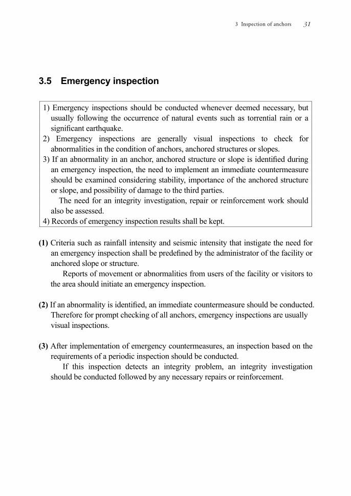
3.5 Emergency inspection
1) Emergency inspections should be conducted whenever deemed necessary, but usually following the occurrence of natural events such as torrential rain or a signicant earthquake.
2) Emergency inspections are generally visual inspections to check for abnormalities in the condition of anchors, anchored structures or slopes.
3) If an abnormality in an anchor, anchored structure or slope is identied during an emergency inspection, the need to implement an immediate countermeasure should be examined considering stability, importance of the anchored structure or slope, and possibility of damage to the third parties. The need for an integrity investigation, repair or reinforcement work should also be assessed.
4) Records of emergency inspection results shall be kept. (1) Criteria such as rainfall intensity and seismic intensity that instigate the need for
an emergency inspection shall be predened by the administrator of the facility or anchored slope or structure.
Reports of movement or abnormalities from users of the facility or visitors to the area should initiate an emergency inspection.
(2) If an abnormality is identied, an immediate countermeasure should be conducted.
Therefore for prompt checking of all anchors, emergency inspections are usually visual inspections.
(3) After implementation of emergency countermeasures, an inspection based on the
requirements of a periodic inspection should be conducted. If this inspection detects an integrity problem, an integrity investigation
should be conducted followed by any necessary repairs or reinforcement.
3 Inspection of anchors 31
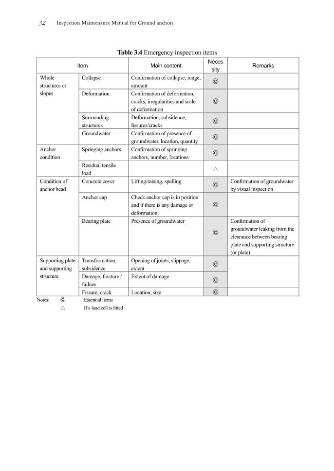
Table 3.4 Emergency inspection items
Item Main content Neces
sity Remarks
Whole structures or slopes
Collapse Conrmation of collapse, range, amount
㉧
Deformation Conrmation of deformation, cracks, irregularities and scale of deformation
㉧
Surrounding structures
Deformation, subsidence, ssures/cracks
㉧
Groundwater
Conrmation of presence of groundwater, location, quantity
㉧
Anchor condition
Springing anchors Conrmation of springing anchors, number, locations
㉧
Residual tensile load
△
Condition of anchor head
Concrete cover Lifting/raising, spalling ㉧ Conrmation of groundwater by visual inspection
Anchor cap Check anchor cap is in position and if there is any damage or deformation
㉧
Bearing plate Presence of groundwater
㉧
Conrmation of groundwater leaking from the clearance between bearing plate and supporting structure (or plate)
Supporting plate and supporting structure
Transformation, subsidence
Opening of joints, slippage, extent
㉧
Damage, fracture / failure
Extent of damage ㉧
Fissure, crack Location, size ㉧ Notes: ㉧ Essential items △ If a load cell is tted
Inspection Maintenance Manual for Ground anchors32
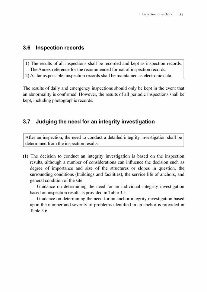
3.6 Inspection records
1) The results of all inspections shall be recorded and kept as inspection records. The Annex reference for the recommended format of inspection records.
2) As far as possible, inspection records shall be maintained as electronic data. The results of daily and emergency inspections should only be kept in the event that an abnormality is conrmed. However, the results of all periodic inspections shall be kept, including photographic records.
3.7 Judging the need for an integrity investigation
After an inspection, the need to conduct a detailed integrity investigation shall be determined from the inspection results.
(1) The decision to conduct an integrity investigation is based on the inspection
results, although a number of considerations can inuence the decision such as degree of importance and size of the structures or slopes in question, the surrounding conditions (buildings and facilities), the service life of anchors, and general condition of the site.
Guidance on determining the need for an individual integrity investigation based on inspection results is provided in Table 3.5.
Guidance on determining the need for an anchor integrity investigation based upon the number and severity of problems identied in an anchor is provided in Table 3.6.
3 Inspection of anchors 33
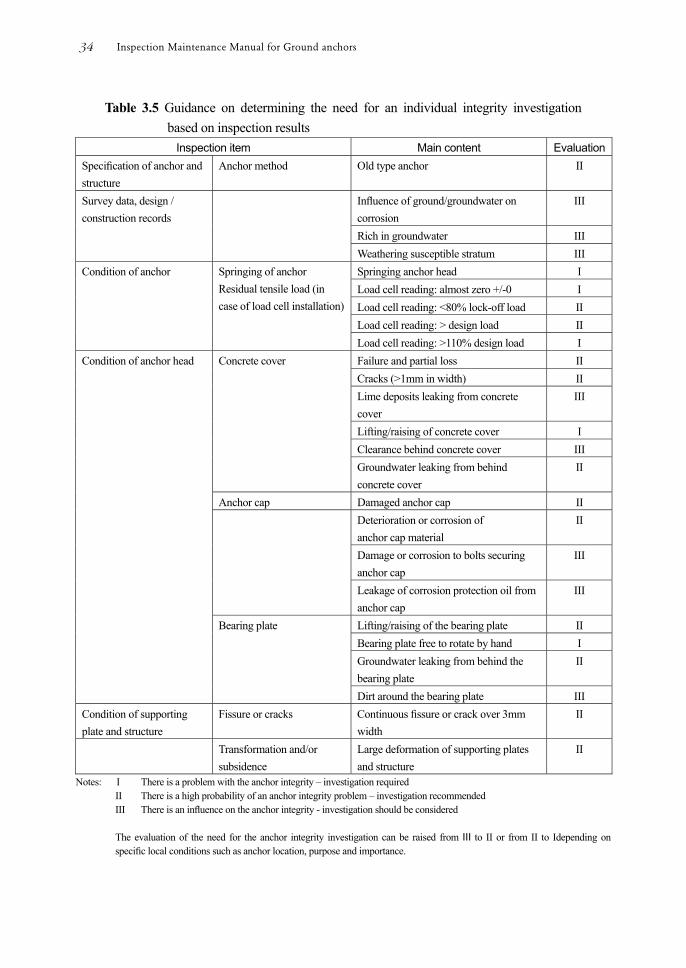
Table 3.5 Guidance on determining the need for an individual integrity investigation based on inspection results
Inspection item Main content EvaluationSpecication of anchor and structure
Anchor method Old type anchor II
Survey data, design / construction records
Inuence of ground/groundwater on corrosion
III
Rich in groundwater III Weathering susceptible stratum III
Condition of anchor Springing of anchor Residual tensile load (in case of load cell installation)
Springing anchor head I Load cell reading: almost zero +/-0 I Load cell reading: <80% lock-off load II Load cell reading: > design load II Load cell reading: >110% design load I
Condition of anchor head Concrete cover Failure and partial loss II Cracks (>1mm in width) II Lime deposits leaking from concrete cover
III
Lifting/raising of concrete cover I Clearance behind concrete cover III Groundwater leaking from behind concrete cover
II
Anchor cap Damaged anchor cap II Deterioration or corrosion of
anchor cap material II
Damage or corrosion to bolts securing anchor cap
III
Leakage of corrosion protection oil from anchor cap
III
Bearing plate Lifting/raising of the bearing plate II Bearing plate free to rotate by hand I Groundwater leaking from behind the bearing plate
II
Dirt around the bearing plate III Condition of supporting plate and structure
Fissure or cracks Continuous ssure or crack over 3mm width
II
Transformation and/or subsidence
Large deformation of supporting plates and structure
II
Notes: I There is a problem with the anchor integrity – investigation required II There is a high probability of an anchor integrity problem – investigation recommended III There is an inuence on the anchor integrity - investigation should be considered The evaluation of the need for the anchor integrity investigation can be raised from Ⅲ to II or from II to Idepending on specic local conditions such as anchor location, purpose and importance.
Inspection Maintenance Manual for Ground anchors34

Table 3.6 Guidance on determining the need for an anchor integrity investigation Result of evaluation
Judgment Action Evaluation Number of problems
I II III
one or more two or more three or more
Detailed investigation is necessary because high possibility of anchor problem
Conduct integrity investigation
(2) The content and the procedure of integrity investigations are described in Chapter 4.
If the inspection indicates that there is a very high possibility of an anchor integrity problem and third party damage is likely to occur, emergency countermeasure should be taken prior to implementation of the integrity investigation.
The integrity investigation should be conducted after the risk of damage to third parties has been mitigated.
If the inspection results do not t the evaluations shown in Table 3.5, an integrity investigation shall be conducted for the following cases: -
① In the case that an abnormality can be found in some of the anchored structures
or slopes but cannot be detected in individual anchors. ② In the case that slight abnormalities due to a similar cause occur in a number of
anchors within a limited or wider area, even if an integrity investigation is not required for each anchor.
③ In the case that no integrity investigations have been conducted on anchors that
have been in service for a long period.
3 Inspection of anchors 35

Inspection Maintenance Manual for Ground anchors2

4 Integrity investigation of anchors
4.1 Basic concept and flow of integrity investigation
During an integrity investigation the condition of anchors is conrmed in detail and anchor integrity shall be evaluated. 1) Prior to an integrity investigation a preliminary survey shall be conducted and
reference data should be collected. 2) An integrity investigation plan shall be formulated based on the results of the
preliminary survey and inspection. The investigation shall be conducted systematically and efciently.
3) A suitable method of integrity investigation shall be determined considering the situation of the targeted anchors and condition of the site.
4) The integrity of anchored structures or slopes shall be evaluated based on the results of the integrity investigation of each anchor.
5) Contents and results of integrity investigations shall be recorded and stored for future reference.
An integrity investigation should be conducted for all anchors whenever judged necessary from the inspection results. (1) Preliminary survey
The method of integrity investigation depends on the anchor specication and condition of the site and surrounding environment. A preliminary survey is therefore necessary to decide the appropriate type and method of integrity investigation.
(2) Integrity investigation planning
An integrity investigation should be carefully planned with consideration given to the type of tests to be adopted and how they are to be executed based on the data collected during the preliminary survey.
Planning shall include a detailed step by step approach to the method and
4 Integrity investigation of anchors 37
management of the integrity investigation, with consideration given to the overall security of the site and conservation of the surrounding area and environment.
Integrity investigations are generally conducted for all anchors whenever judged necessary. However, in the case that there are a large number of anchors and the abnormalities displayed can be judged to be of a similar cause, a random sample of the anchors can be selected for integrity investigation.
If the results of the integrity investigations are similar, they can then be applied to all the anchors within the group and common countermeasures can be implemented.
If an inspection of an anchor does not highlight an abnormality, yet integrity investigations on neighboring anchors have revealed abnormalities, additional investigations should be undertaken in order to fully conrm the integrity of the anchored slope or structure.
As the results of the integrity investigation will form the basis for selecting the countermeasures and how they are to be implemented, due consideration, including making provisions for additional investigations, should be given to the potential for the abnormality to re-occur and the countermeasure selected in order to mitigate the risk of having to repeat or implement new countermeasures in the future.
(3) Selecting the method of integrity investigation
An effective and efcient method shall be selected and implemented. (4) Evaluation of the integrity investigation results
The result of integrity investigations shall conrm the integrity of each anchor and shall be evaluated collectively considering the design standard of the anchored structures or slopes.
If the integrity investigation shows there is a risk of damage to third parties unless emergency countermeasures are taken, the emergency countermeasures should be implemented to mitigate the risk of damage prior to examining longer term countermeasure options.
4.2 Integrity investigation planning
An integrity investigation should be carefully planned with consideration given to the type of tests to be adopted and how they are to be executed based on the data collected in the preliminary survey.
Inspection Maintenance Manual for Ground anchors38

Planning should include a detailed step-by-step approach to the method and management of the integrity investigation with consideration given the overall security of the site and conservation of the surrounding area and environment.
Once it has been determined that an integrity investigation is physically possible and tests can be conducted practically, considering safety and economy, the integrity investigation should be carefully planned based on information collected during the preliminary survey.
The plan shall examine the outline of the site, specication of anchors, place of implementation, investigation items, implementation system, investigation method and countermeasure after investigation.
The general items included in an integrity investigation plan are shown in Table 4-1. The actual plan content depends on the specic situation.
Guidance on the number of anchors to be selected for integrity investigation is provided in Table 4.2
Table 4.1 Integrity investigation planning Item Content
1. Summary ・Construction name ・Location ・General Contractor ・Anchor Contractor ・Anchor Purpose ・Year installed ・Other
2. Ground conditions ・Geology – cross section ・Geology - prole
3. Integrity investigation purpose 4. Regime ・Responsible Person 5. Investigation points ・Reasons for selecting investigation points 6. Items of integrity investigation ・Reasons for selecting items 7. Specication of anchors ・Method and Type
・Tendon Tensile strength ・Anchor free length, Anchor bond length ・Design Load ・Lock-Off Load ・Other
8. Integrity investigation procedure 9. Restoration after investigation
4 Integrity investigation of anchors 39
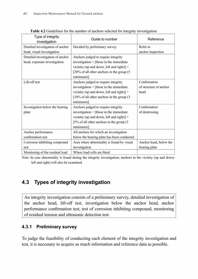
Table 4.2 Guidelines for the number of anchors selected for integrity investigation Type of integrity
investigation Guide to number Reference
Detailed investigation of anchor head, visual investigation
Decided by preliminary survey Refer to anchor inspection
Detailed investigation of anchor head, exposure investigation
Anchors judged to require integrity investigation + [those in the immediate vicinity (up and down, left and right)] + [20% of all other anchors in the group (5 minimum)]
Lift-off test Anchors judged to require integrity investigation + [those in the immediate vicinity (up and down, left and right)] + [10% of all other anchors in the group (3 minimum)]
Conrmation of structure of anchor head
Investigation below the bearing plate
Anchors judged to require integrity investigation + [those in the immediate vicinity (up and down, left and right)] + [5% of all other anchors in the group (3 minimum)]
Conrmation of destressing
Anchor performance conrmation test
All anchors for which an investigation below the bearing plate has been conducted.
Corrosion inhibiting compound test
Area where abnormality is found by visual investigation
Anchor head, below the bearing plate
Monitoring of the residual load Where load cells are tted Note:In case abnormality is found during the integrity investigation, anchors in the vicinity (up and down-
left and right) will also be examined.
4.3 Types of integrity investigation
An integrity investigation consists of a preliminary survey, detailed investigation of the anchor head, lift-off test, investigation below the anchor head, anchor performance conrmation test, test of corrosion inhibiting compound, monitoring of residual tension and ultrasonic detection test.
4.3.1 Preliminary survey To judge the feasibility of conducting each element of the integrity investigation and test, it is necessary to acquire as much information and reference data as possible.
Inspection Maintenance Manual for Ground anchors40
(1) Investigation of existing information Specication of anchors, condition of anchors, condition of anchor heads, existence of deformation of bearing plate and all other relevant information should be investigated from existing records such as the preliminary survey for anchor maintenance (record for maintenance management etc.), daily inspection, periodic inspection and emergency inspection.
(2) Investigation of sites
Casting position of anchors shall be conrmed by inspecting the appearance of anchored structures or slopes and comparing received drawings with the situation on site.
(3) Initial visual inspection
A visual inspection of each anchor head and general conditions in the vicinity should be conducted
① Condition of anchor head protection
The anchor head cap shall be checked for any deterioration or damage and that it is securely xed. In case that anchor heads are covered with concrete, the concrete should be checked for deterioration, damage, existence of lime deposits and lifting.
② Investigation of anchored structures or slopes and general local conditions
The existence of cracks and evidence of any movement of anchored structures or slopes shall be conrmed. Also, any water emerging from the vicinity of the anchor position shall be identied and water quality investigated if necessary.
4.3.2 Detailed investigation of the anchor heads (1) Classication of anchor heads
Anchor heads are generally those shown in Figures 4.2 – 4.4. Some anchor heads have no cover at all (Figure 4.4).
① Concrete cover
The anchor heads are set in a frame and covered by concrete or mortar. This was the method commonly applied to old type anchors.
Problems xing the wedges are common because of direct casting of the
4 Integrity investigation of anchors 41
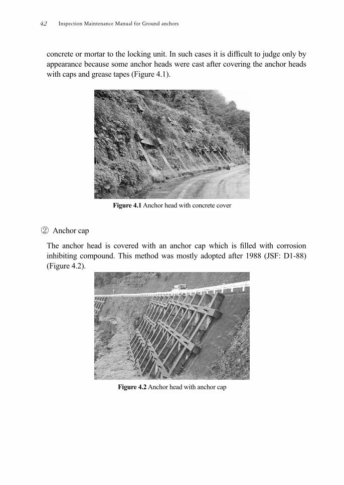
concrete or mortar to the locking unit. In such cases it is difcult to judge only by appearance because some anchor heads were cast after covering the anchor heads with caps and grease tapes (Figure 4.1).
Figure 4.1 Anchor head with concrete cover
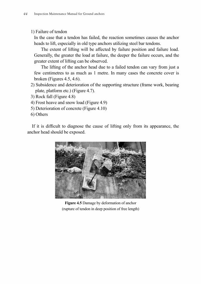
② Anchor cap
The anchor head is covered with an anchor cap which is lled with corrosion inhibiting compound. This method was mostly adopted after 1988 (JSF: D1-88) (Figure 4.2).
Figure 4.2 Anchor head with anchor cap
Inspection Maintenance Manual for Ground anchors42

③ Simple protection of anchor heads (Figure 4.3)
Figure 4.3 Simple protection of anchor head with pvc pipe
④ Anchor heads without protection (Figure 4.4)
Figure 4.4 Anchor heads without protection
(2) Appearance inspection
Deformations occurring at the anchor head are usually an indication of an anchor problem, which is why daily visual inspections are most important.
The nature of the anchor problem can often be determined from the deformation at the anchor head.
① Deformation of concrete cover
In the case of directly applied concrete covers, lifting, dropping off and damage to the cover are the main types of deformation that can be observed.
The main causes of such deformation are as follows.
4 Integrity investigation of anchors 43
1) Failure of tendon In the case that a tendon has failed, the reaction sometimes causes the anchor heads to lift, especially in old type anchors utilizing steel bar tendons.
The extent of lifting will be affected by failure position and failure load. Generally, the greater the load at failure, the deeper the failure occurs, and the greater extent of lifting can be observed.
The lifting of the anchor head due to a failed tendon can vary from just a few centimetres to as much as 1 metre. In many cases the concrete cover is broken (Figures 4.5, 4.6).
2) Subsidence and deterioration of the supporting structure (frame work, bearing plate, platform etc.) (Figure 4.7).
3) Rock fall (Figure 4.8) 4) Frost heave and snow load (Figure 4.9) 5) Deterioration of concrete (Figure 4.10) 6) Others If it is difcult to diagnose the cause of lifting only from its appearance, the
anchor head should be exposed.
Figure 4.5 Damage by deformation of anchor
(rupture of tendon in deep position of free length)
Inspection Maintenance Manual for Ground anchors44
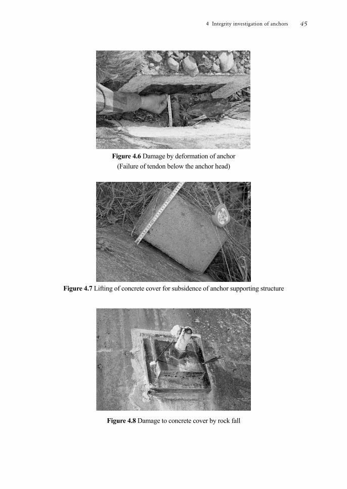
Figure 4.6 Damage by deformation of anchor
(Failure of tendon below the anchor head)
Figure 4.7 Lifting of concrete cover for subsidence of anchor supporting structure
Figure 4.8 Damage to concrete cover by rock fall
4 Integrity investigation of anchors 45
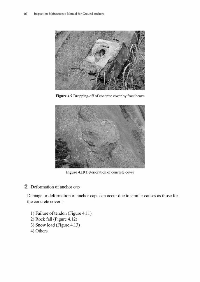
Figure 4.9 Dropping-off of concrete cover by frost heave
Figure 4.10 Deterioration of concrete cover
② Deformation of anchor cap
Damage or deformation of anchor caps can occur due to similar causes as those for the concrete cover: -
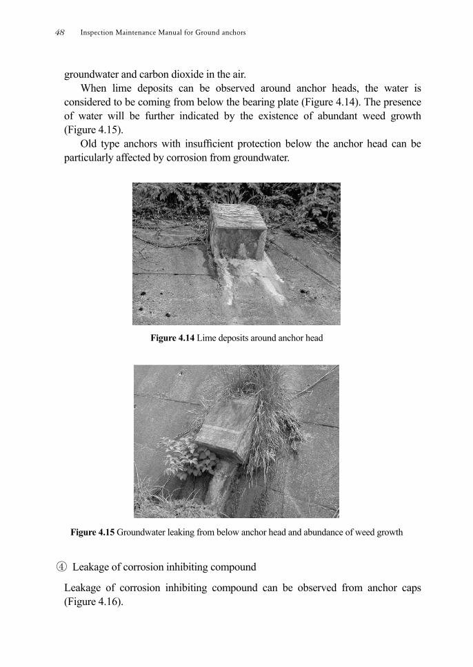
1) Failure of tendon (Figure 4.11) 2) Rock fall (Figure 4.12) 3) Snow load (Figure 4.13) 4) Others
Inspection Maintenance Manual for Ground anchors46
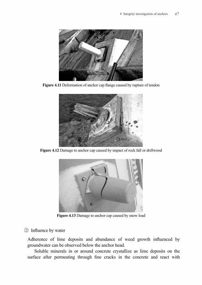
Figure 4.11 Deformation of anchor cap ange caused by rupture of tendon
Figure 4.12 Damage to anchor cap caused by impact of rock fall or driftwood
Figure 4.13 Damage to anchor cap caused by snow load
③ Inuence by water
Adherence of lime deposits and abundance of weed growth inuenced by groundwater can be observed below the anchor head.
Soluble minerals in or around concrete crystallize as lime deposits on the surface after permeating through ne cracks in the concrete and react with
4 Integrity investigation of anchors 47
groundwater and carbon dioxide in the air. When lime deposits can be observed around anchor heads, the water is
considered to be coming from below the bearing plate (Figure 4.14). The presence of water will be further indicated by the existence of abundant weed growth (Figure 4.15).
Old type anchors with insufcient protection below the anchor head can be particularly affected by corrosion from groundwater.
Figure 4.14 Lime deposits around anchor head
Figure 4.15 Groundwater leaking from below anchor head and abundance of weed growth
④ Leakage of corrosion inhibiting compound
Leakage of corrosion inhibiting compound can be observed from anchor caps (Figure 4.16).
Inspection Maintenance Manual for Ground anchors48
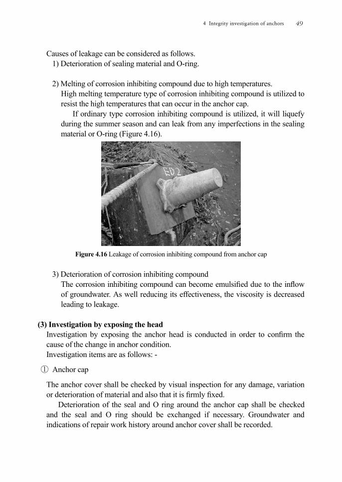
Causes of leakage can be considered as follows. 1) Deterioration of sealing material and O-ring. 2) Melting of corrosion inhibiting compound due to high temperatures.
High melting temperature type of corrosion inhibiting compound is utilized to resist the high temperatures that can occur in the anchor cap.
If ordinary type corrosion inhibiting compound is utilized, it will liquefy during the summer season and can leak from any imperfections in the sealing material or O-ring (Figure 4.16).
Figure 4.16 Leakage of corrosion inhibiting compound from anchor cap
3) Deterioration of corrosion inhibiting compound
The corrosion inhibiting compound can become emulsied due to the inow of groundwater. As well reducing its effectiveness, the viscosity is decreased leading to leakage.
(3) Investigation by exposing the head
Investigation by exposing the anchor head is conducted in order to conrm the cause of the change in anchor condition. Investigation items are as follows: -
① Anchor cap
The anchor cover shall be checked by visual inspection for any damage, variation or deterioration of material and also that it is rmly xed.
Deterioration of the seal and O ring around the anchor cap shall be checked and the seal and O ring should be exchanged if necessary. Groundwater and indications of repair work history around anchor cover shall be recorded.
4 Integrity investigation of anchors 49
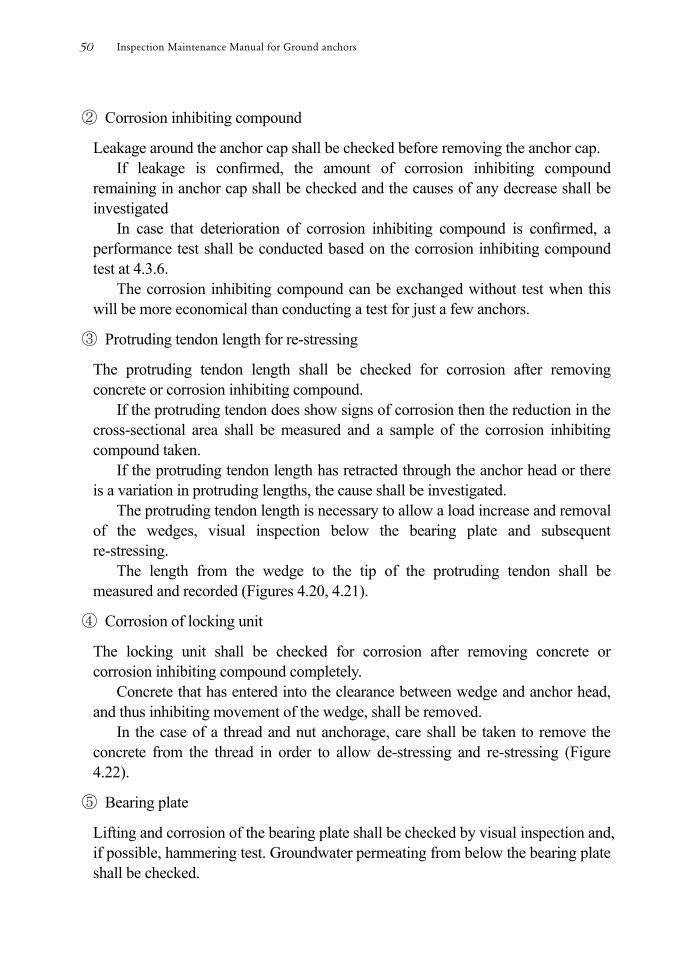
② Corrosion inhibiting compound
Leakage around the anchor cap shall be checked before removing the anchor cap. If leakage is conrmed, the amount of corrosion inhibiting compound
remaining in anchor cap shall be checked and the causes of any decrease shall be investigated
In case that deterioration of corrosion inhibiting compound is conrmed, a performance test shall be conducted based on the corrosion inhibiting compound test at 4.3.6.
The corrosion inhibiting compound can be exchanged without test when this will be more economical than conducting a test for just a few anchors.
③ Protruding tendon length for re-stressing
The protruding tendon length shall be checked for corrosion after removing concrete or corrosion inhibiting compound.
If the protruding tendon does show signs of corrosion then the reduction in the cross-sectional area shall be measured and a sample of the corrosion inhibiting compound taken.
If the protruding tendon length has retracted through the anchor head or there is a variation in protruding lengths, the cause shall be investigated.
The protruding tendon length is necessary to allow a load increase and removal of the wedges, visual inspection below the bearing plate and subsequent re-stressing.
The length from the wedge to the tip of the protruding tendon shall be measured and recorded (Figures 4.20, 4.21).
④ Corrosion of locking unit
The locking unit shall be checked for corrosion after removing concrete or corrosion inhibiting compound completely.
Concrete that has entered into the clearance between wedge and anchor head, and thus inhibiting movement of the wedge, shall be removed.
In the case of a thread and nut anchorage, care shall be taken to remove the concrete from the thread in order to allow de-stressing and re-stressing (Figure 4.22).
⑤ Bearing plate
Lifting and corrosion of the bearing plate shall be checked by visual inspection and, if possible, hammering test. Groundwater permeating from below the bearing plate shall be checked.
Inspection Maintenance Manual for Ground anchors50
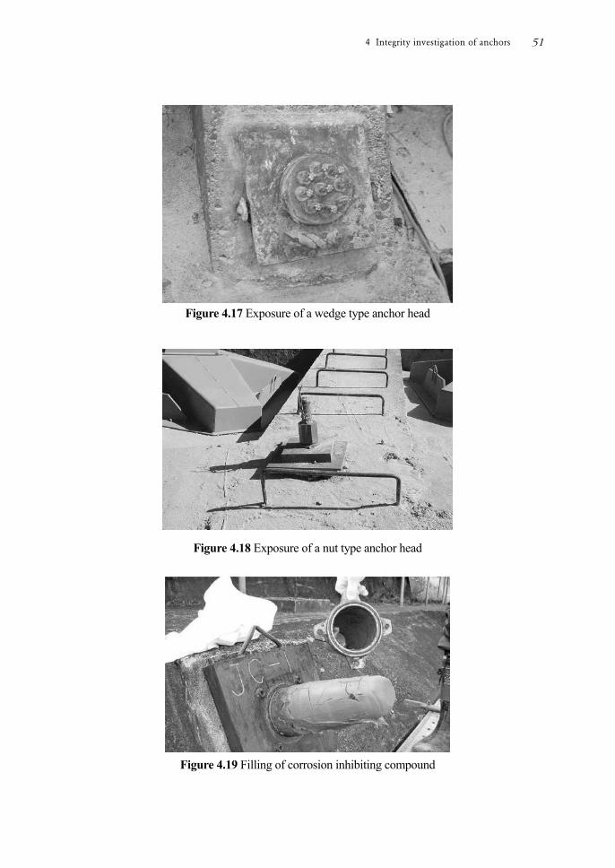
Figure 4.17 Exposure of a wedge type anchor head
Figure 4.18 Exposure of a nut type anchor head
Figure 4.19 Filling of corrosion inhibiting compound
4 Integrity investigation of anchors 51
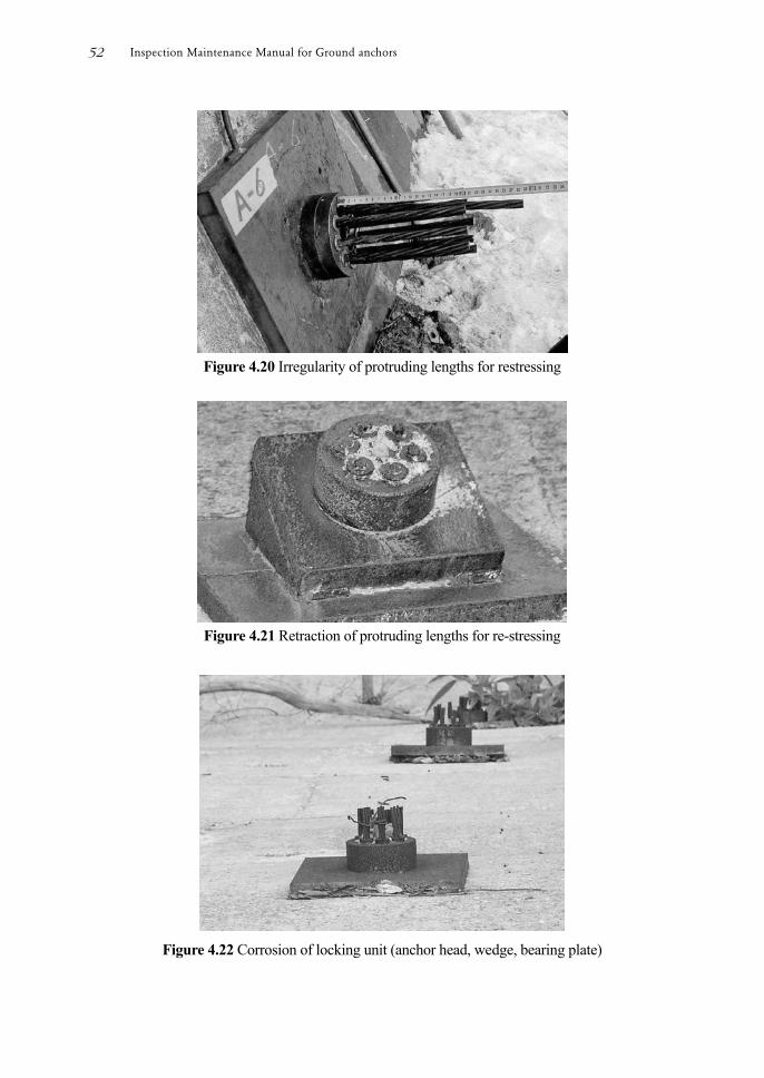
Figure 4.20 Irregularity of protruding lengths for restressing
Figure 4.21 Retraction of protruding lengths for re-stressing
Figure 4.22 Corrosion of locking unit (anchor head, wedge, bearing plate)
Inspection Maintenance Manual for Ground anchors52

(4) Investigation of corrosion inhibiting compound Over a long period of time deterioration and a reduction in the level of corrosion inhibiting compound that is protecting the anchor head can occur.
Deterioration is caused by the effects of mixing with air and water, and environmental conditions such as temperature change.
Leakage of corrosion inhibiting compound can occur below the anchor head and from around the anchor cap.
Leakage below the anchor head can be observed in old type anchors, especially in the nut type anchors, and leakage can also be observed from the clearance between the wedge and anchor head.
Leakage from around the anchor cap can occur due to deterioration of the O-ring in the anchor cap and deterioration of the seal material.
If deterioration or shortage of lling is identied during the investigation, the causes of the leakage shall be rectied and the corrosion inhibiting compound topped up or replaced.
The corrosion inhabiting compound should be undergo further examination and testing as described in section 4.3.6.
Figure 4.23 Leakage of corrosion inhibiting compound (grease)
Figure 4.24 Deterioration of corrosion inhibiting compound (grease)
4 Integrity investigation of anchors 53
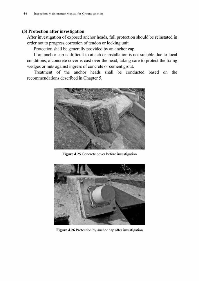
(5) Protection after investigation After investigation of exposed anchor heads, full protection should be reinstated in order not to progress corrosion of tendon or locking unit.
Protection shall be generally provided by an anchor cap. If an anchor cap is difcult to attach or installation is not suitable due to local
conditions, a concrete cover is cast over the head, taking care to protect the xing wedges or nuts against ingress of concrete or cement grout.
Treatment of the anchor heads shall be conducted based on the recommendations described in Chapter 5.
Figure 4.25 Concrete cover before investigation
Figure 4.26 Protection by anchor cap after investigation
Inspection Maintenance Manual for Ground anchors54
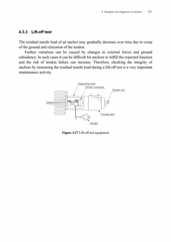
4.3.3 Lift-off test The residual tensile load of an anchor may gradually decrease over time due to creep of the ground and relaxation of the tendon.
Further variations can be caused by changes in external forces and ground subsidence. In such cases it can be difcult for anchors to fulll the expected function and the risk of tendon failure can increase. Therefore, checking the integrity of anchors by measuring the residual tensile load during a lift-off test is a very important maintenance activity.
Figure 4.27 Lift-off test equipment
4 Integrity investigation of anchors 55
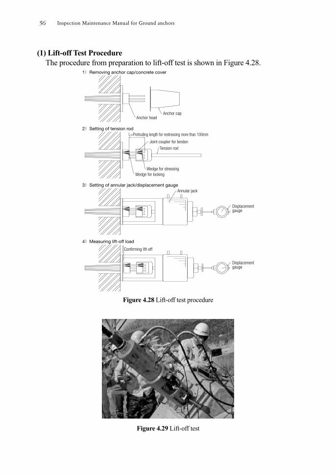
(1) Lift-off Test Procedure The procedure from preparation to lift-off test is shown in Figure 4.28.
Figure 4.28 Lift-off test procedure
Figure 4.29 Lift-off test
Inspection Maintenance Manual for Ground anchors56

(2) Test methods The planned maximum load shall be set at the lower of 1.5 times the anchor design load or 90% of the tendon yield strength when it is possible to conrm the anchor specication from the construction report.
If the design load cannot be conrmed, the planned maximum load shall be 90% of tendon yield strength.
Small load increments are preferable and generally set at 10 to 20kN intervals. The load and head displacement is measured. Simple loading shall be applied
and head displacement shall be measured when the load is stabilized after being applied at a constant rate.
When the point of lift-off is reached during the test, measurements are taken at a further 3 load increments before the test is completed by reducing the load to the initial level.
(3) Classication and judgment of test results
A load vs. displacement curve is drawn from the measurement results as shown in the example at Figure 4.30. The load at the point of inection is the residual tensile load.
The integrity of an anchor is judged by comparing this residual tensile load with the lock–off load or design load for the anchor.
The apparent free anchor length and anchor abnormalities can be determined from the load vs. displacement curve.
Figure 4.30 Load vs. displacement curve
4 Integrity investigation of anchors 57
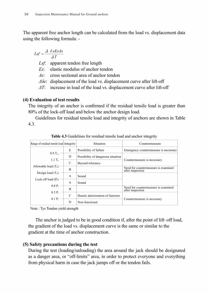
The apparent free anchor length can be calculated from the load vs. displacement data using the following formula: -
TeEsAsLsf
Δ
Δδ
Lsf: apparent tendon free length Es: elastic modulus of anchor tendon As: cross sectional area of anchor tendon Δδe: displacement of the load vs. displacement curve after lift-off ΔT: increase in load of the load vs. displacement curve after lift-off
(4) Evaluation of test results
The integrity of an anchor is conrmed if the residual tensile load is greater than 80% of the lock-off load and below the anchor design load.
Guidelines for residual tensile load and integrity of anchors are shown in Table 4.3.
Table 4.3 Guidelines for residual tensile load and anchor integrity
Note : Tys Tendon yield strength
The anchor is judged to be in good condition if, after the point of lift–off load,
the gradient of the load vs. displacement curve is the same or similar to the gradient at the time of anchor construction.
(5) Safety precautions during the test
During the test (loading/unloading) the area around the jack should be designated as a danger area, or “off-limits” area, in order to protect everyone and everything from physical harm in case the jack jumps off or the tendon fails.
Inspection Maintenance Manual for Ground anchors58
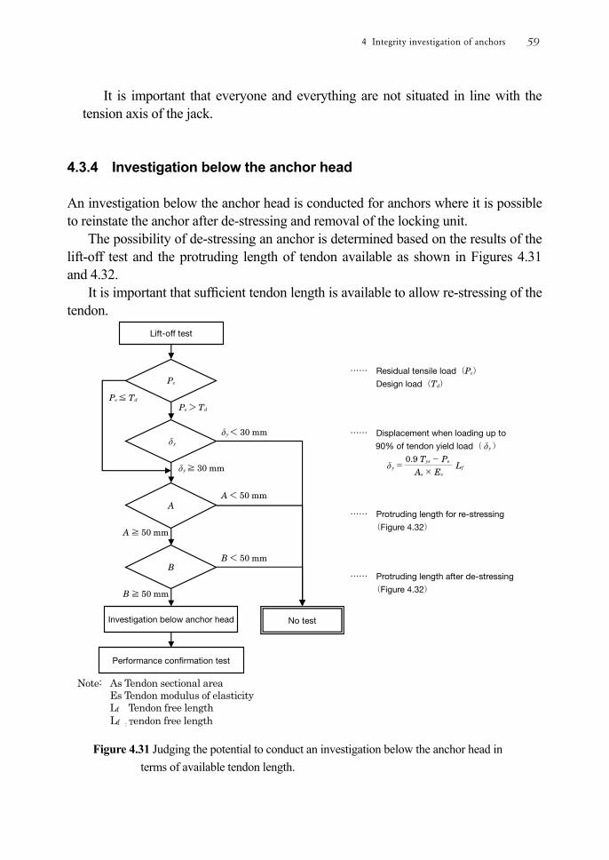
It is important that everyone and everything are not situated in line with the tension axis of the jack.
4.3.4 Investigation below the anchor head An investigation below the anchor head is conducted for anchors where it is possible to reinstate the anchor after de-stressing and removal of the locking unit.
The possibility of de-stressing an anchor is determined based on the results of the lift-off test and the protruding length of tendon available as shown in Figures 4.31 and 4.32.
It is important that sufcient tendon length is available to allow re-stressing of the tendon.
Note: As Tendon sectional area
Es Tendon modulus of elasticity Lf Tendon free length Lf :Tendon free length
Figure 4.31 Judging the potential to conduct an investigation below the anchor head in terms of available tendon length.
4 Integrity investigation of anchors 59
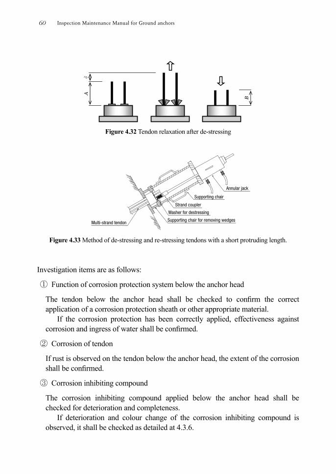
Figure 4.32 Tendon relaxation after de-stressing
Figure 4.33 Method of de-stressing and re-stressing tendons with a short protruding length.
Investigation items are as follows:
① Function of corrosion protection system below the anchor head
The tendon below the anchor head shall be checked to conrm the correct application of a corrosion protection sheath or other appropriate material.
If the corrosion protection has been correctly applied, effectiveness against corrosion and ingress of water shall be conrmed.
② Corrosion of tendon
If rust is observed on the tendon below the anchor head, the extent of the corrosion shall be conrmed.
③ Corrosion inhibiting compound
The corrosion inhibiting compound applied below the anchor head shall be checked for deterioration and completeness.
If deterioration and colour change of the corrosion inhibiting compound is observed, it shall be checked as detailed at 4.3.6.
Inspection Maintenance Manual for Ground anchors60
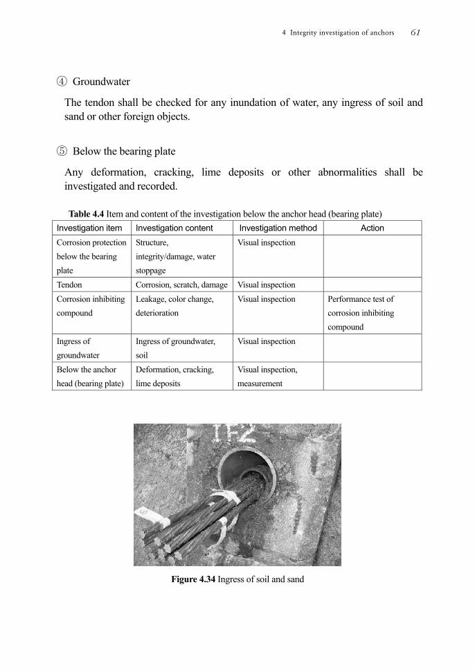
④ Groundwater
The tendon shall be checked for any inundation of water, any ingress of soil and sand or other foreign objects.
⑤ Below the bearing plate
Any deformation, cracking, lime deposits or other abnormalities shall be investigated and recorded.
Table 4.4 Item and content of the investigation below the anchor head (bearing plate)
Investigation item Investigation content Investigation method Action Corrosion protection below the bearing plate
Structure, integrity/damage, water stoppage
Visual inspection
Tendon Corrosion, scratch, damage Visual inspection Corrosion inhibiting compound
Leakage, color change, deterioration
Visual inspection Performance test of corrosion inhibiting compound
Ingress of groundwater
Ingress of groundwater, soil
Visual inspection
Below the anchor head (bearing plate)
Deformation, cracking, lime deposits
Visual inspection, measurement
Figure 4.34 Ingress of soil and sand
4 Integrity investigation of anchors 61
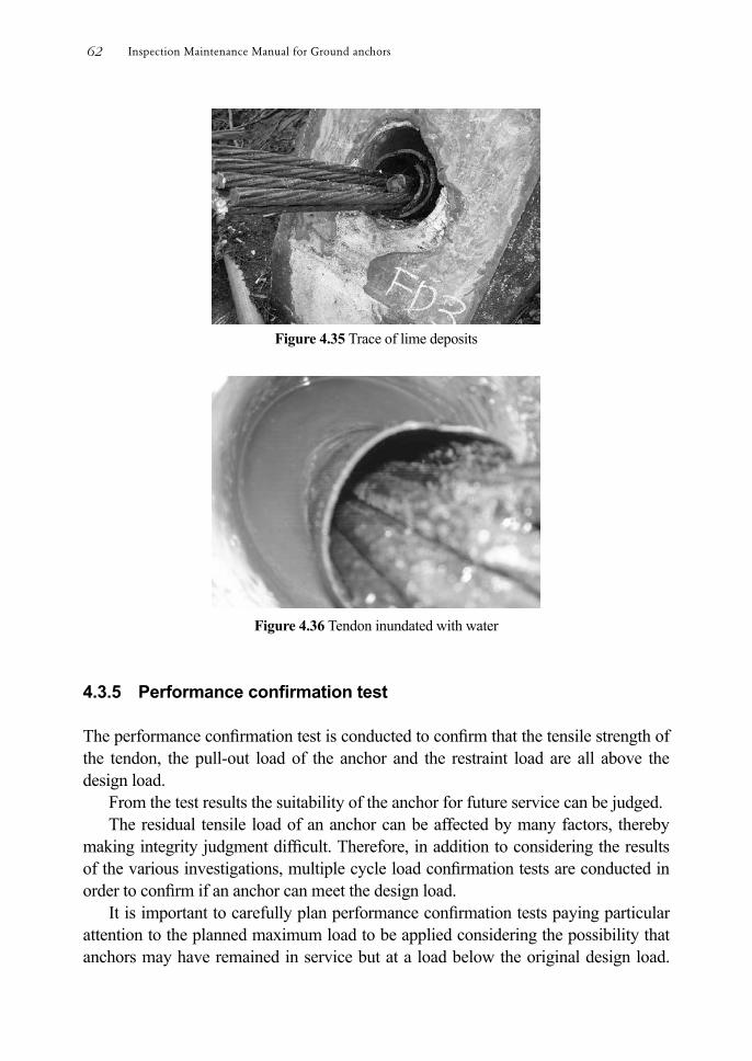
Figure 4.35 Trace of lime deposits
Figure 4.36 Tendon inundated with water
4.3.5 Performance conrmation test The performance conrmation test is conducted to conrm that the tensile strength of the tendon, the pull-out load of the anchor and the restraint load are all above the design load.
From the test results the suitability of the anchor for future service can be judged. The residual tensile load of an anchor can be affected by many factors, thereby
making integrity judgment difcult. Therefore, in addition to considering the results of the various investigations, multiple cycle load conrmation tests are conducted in order to conrm if an anchor can meet the design load.
It is important to carefully plan performance conrmation tests paying particular attention to the planned maximum load to be applied considering the possibility that anchors may have remained in service but at a load below the original design load.
Inspection Maintenance Manual for Ground anchors62

Such anchors could be overstressed and damaged during the test. (1) Loading method and procedure
The planned maximum load during the test shall be within 1.5 times the design load (normal conditions), or 1.0 times the design seismic load, and less than 90% yield strength of the tendon.
In case that the designed working load is not available because of missing records, the maximum load applied shall be below 90% of yield strength.
Setting of the maximum applied load is the responsibility of the test engineer after consideration of the results of the detailed investigation of the anchor head and investigation below the anchor head. It should also be assumed that the tensile strength of the tendon could have been reduced due to corrosion.
The loading procedure for the test is shown in Table 4.5 and loading plan is shown in Figure 4.37.
Table 4.5 Loading procedure Number of load steps 5 steps Number of load cycles 5 cycles Initial seating load Approx.10% of planned maximum load Loading rate (example) Up load:
20to10load maximum Planned kN/min constant velocity
Unload: Approx. 2 times × load increments Load holding time (example) Initial load step Hold for at least 10 minutes.
Subsequent load increments
Clay: Hold for at least 2 minutes. Rock, sand: Hold for at least 1 minute.
Figure 4.37 Example of loading plan for rock or sand
4 Integrity investigation of anchors 63

(2) Filing of test results and judgment Load vs. displacement and load vs. elastic/plastic displacement curves are plotted from the test results as illustrated in Figure 4.38.
The apparent free anchor length and the anchor design load safety factor shall be conrmed from the load vs. displacement curve.
The creep coefcient shall be calculated from any load loss during the holding time and long term durability shall be judged.
Figure 4.38 Example of anchor performance conrmation test results
Inspection Maintenance Manual for Ground anchors64

(3) Safety precautions during the test During the test (loading/unloading) the area around the jack shall be designated as a danger area, or “off-limits” area, in order to protect everyone and everything from physical harm in case the jack jumps or the tendon fails.
It is important that operatives are not situated in line with the tension axis of the jack.
4.3.6 Test of corrosion inhibiting compound (Test of CIC) Grease or petrolatum are usually used as corrosion inhibiting compounds in order to prevent corrosion of the tendon and are applied around the anchor head, below the anchor head, and to the tendon free length.
The corrosion inhibiting compound forms a stable oil lm on the metal surface and oxidation of metal is retarded.
If a change or variation in colour of the corrosion inhibiting compound is observed during a detailed investigation of the anchor head or investigation below the bearing plate, a sample of the corrosion inhibiting compound shall be collected and tested.
If deterioration of the corrosion inhibiting compound is conrmed, it shall be renewed after the cause of the deterioration has been identied and resolved. (1) Types of corrosion inhibiting compound
There are two types of corrosion inhibiting compound - grease type and petrolatum type (Table 4.6).
The grease type of corrosion inhibiting compound has a high melting point and is often utilized in the area most susceptible to heat inuence such as the anchor head and below anchor head.
The petrolatum type of corrosion inhibiting compound is often utilized in the area with less inuence of temperature change such as the free anchor length.
4 Integrity investigation of anchors 65
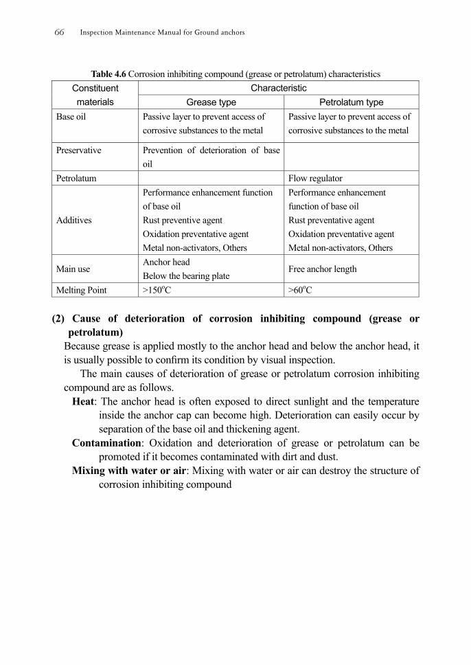
Table 4.6 Corrosion inhibiting compound (grease or petrolatum) characteristics Constituent materials
Characteristic Grease type Petrolatum type
Base oil Passive layer to prevent access of corrosive substances to the metal
Passive layer to prevent access of corrosive substances to the metal
Preservative Prevention of deterioration of base oil
Petrolatum Flow regulator
Additives
Performance enhancement function of base oil Rust preventive agent Oxidation preventative agent Metal non-activators, Others
Performance enhancement function of base oil Rust preventative agent Oxidation preventative agent Metal non-activators, Others
Main use Anchor head Below the bearing plate
Free anchor length
Melting Point >150oC >60oC (2) Cause of deterioration of corrosion inhibiting compound (grease or
petrolatum) Because grease is applied mostly to the anchor head and below the anchor head, it is usually possible to conrm its condition by visual inspection.
The main causes of deterioration of grease or petrolatum corrosion inhibiting compound are as follows.
Heat: The anchor head is often exposed to direct sunlight and the temperature inside the anchor cap can become high. Deterioration can easily occur by separation of the base oil and thickening agent.
Contamination: Oxidation and deterioration of grease or petrolatum can be promoted if it becomes contaminated with dirt and dust.
Mixing with water or air: Mixing with water or air can destroy the structure of corrosion inhibiting compound
Inspection Maintenance Manual for Ground anchors66
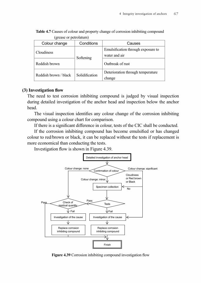
Table 4.7 Causes of colour and property change of corrosion inhibiting compound (grease or petrolatum)
Colour change Conditions Causes
Cloudiness Softening
Emulsication through exposure to water and air
Reddish brown Outbreak of rust
Reddish brown / black Solidication Deterioration through temperature change
(3) Investigation ow
The need to test corrosion inhibiting compound is judged by visual inspection during detailed investigation of the anchor head and inspection below the anchor head.
The visual inspection identies any colour change of the corrosion inhibiting compound using a colour chart for comparison.
If there is a signicant difference in colour, tests of the CIC shall be conducted. If the corrosion inhibiting compound has become emulsied or has changed
colour to red/brown or black, it can be replaced without the tests if replacement is more economical than conducting the tests.
Investigation ow is shown in Figure 4.39.
Figure 4.39 Corrosion inhibiting compound investigation ow
Tests
Investigation of the cause
Detailed investigation of anchor head
Pass
Fail
Specimen collection
Colour change: signicant
Colour change: minor
Finish
Investigation of the cause
Replace corrosion inhibiting compound
Check of residual quantity
No
Pass
Fail
Colour change: none
Cloudiness or Red brown or Black
Confirmation of colour
Replace corrosion inhibiting compound
4 Integrity investigation of anchors 67
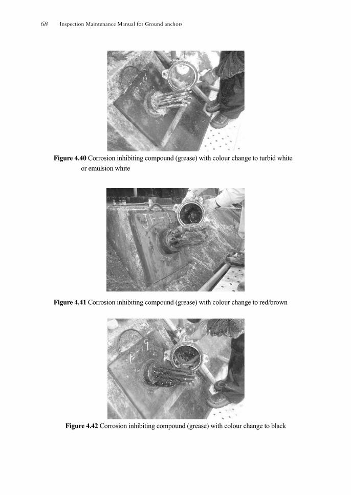
Figure 4.40 Corrosion inhibiting compound (grease) with colour change to turbid white
or emulsion white
Figure 4.41 Corrosion inhibiting compound (grease) with colour change to red/brown
Figure 4.42 Corrosion inhibiting compound (grease) with colour change to black
Inspection Maintenance Manual for Ground anchors68

(4) Corrosion inhibiting compound sample collection A sample of the corrosion inhibiting compound shall be collected from the area where the abnormality can be observed.
Table 4.8 Quantity guidelines for test sample collection.
Test Item Test method Quantity(g) Grease type
Consistency (@25℃, 60W)
JIS K2220 7. 500
Dripping point (temperature at which corrosion inhibiting compound will start to drip) (℃)
JIS K2220 8. 100
Oxidation Stability (99℃, 100hkPa)
JIS K2220 12. 50
Separation (of oil from thickening agent) (100℃, 24h)
JIS K2220 11. 50
Copperplate Corrosion Test (100℃, 24h)
JIS K2220 9. 20
Water JIS K2220 21 50 Infrared Absorption Spectrum (IR)
JIS K2246 100
Petrolatum type
Consistency (@25℃, non-mixture)
JIS K2235 5.10
500
Melting Point (℃)
JIS K2235 5.3 100
Accelerated Corrosion Test: Salt Fog
JIS K2220 5.35
50
Infrared Absorption Spectrum (IR)
JIS K2246 100
Note: JIS is Japanese Industrial Standards (5) Judgment of test results
Oxidation and deterioration of the corrosion inhibiting compound such as grease is caused mainly by water ingress and temperature change. Therefore, the need to change the corrosion inhibiting compound shall be based on the visible colour change and, if necessary, the results of an immersion test.
Test items and inuence on quality deterioration are shown in Table 4.9. The test results shall be assessed carefully on test items for the effectiveness of
corrosion protection. Advice shall be sought from corrosion protection specialists.
4 Integrity investigation of anchors 69
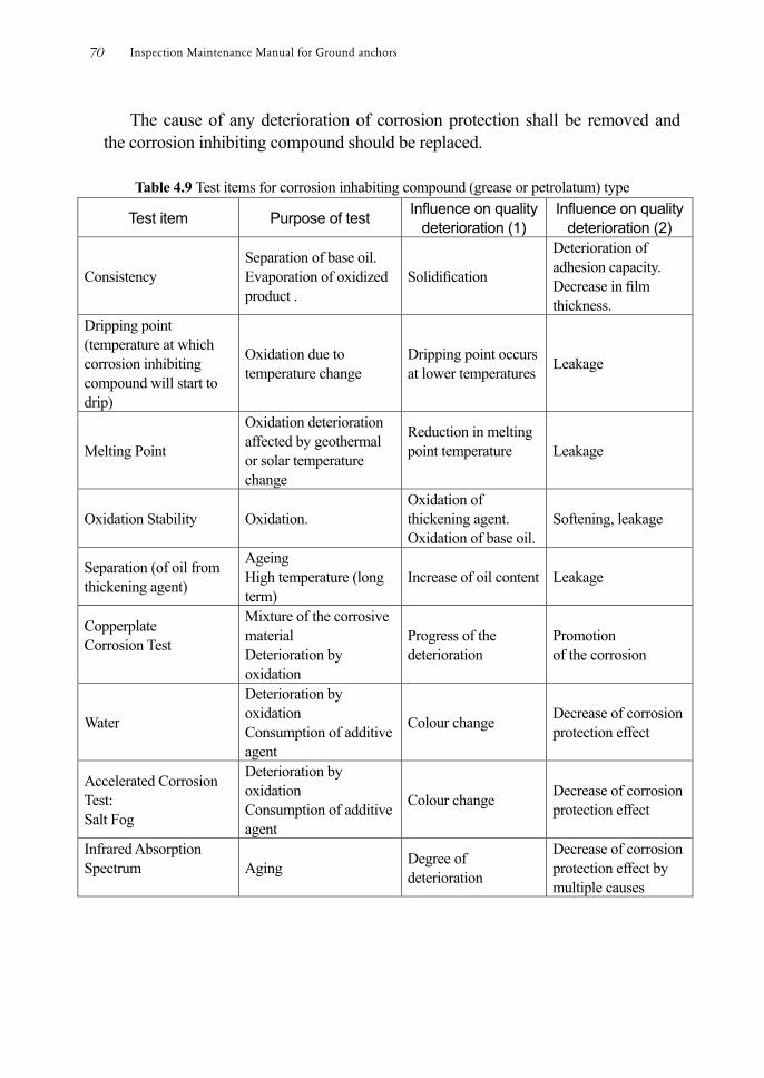
The cause of any deterioration of corrosion protection shall be removed and the corrosion inhibiting compound should be replaced.
Table 4.9 Test items for corrosion inhabiting compound (grease or petrolatum) type
Test item Purpose of test Influence on quality deterioration (1)
Influence on quality deterioration (2)
Consistency Separation of base oil. Evaporation of oxidized product .
Solidication
Deterioration of adhesion capacity. Decrease in lm thickness.
Dripping point (temperature at which corrosion inhibiting compound will start to drip)
Oxidation due to temperature change
Dripping point occurs at lower temperatures Leakage
Melting Point
Oxidation deterioration affected by geothermal or solar temperature change
Reduction in melting point temperature
Leakage
Oxidation Stability Oxidation. Oxidation of thickening agent. Oxidation of base oil.
Softening, leakage
Separation (of oil from thickening agent)
Ageing High temperature (long term)
Increase of oil content Leakage
Copperplate Corrosion Test
Mixture of the corrosive material Deterioration by oxidation
Progress of the deterioration
Promotion of the corrosion
Water
Deterioration by oxidation Consumption of additive agent
Colour change Decrease of corrosion protection effect
Accelerated Corrosion Test: Salt Fog
Deterioration by oxidation Consumption of additive agent
Colour change Decrease of corrosion protection effect
Infrared Absorption Spectrum
Aging Degree of deterioration
Decrease of corrosion protection effect by multiple causes
Inspection Maintenance Manual for Ground anchors70
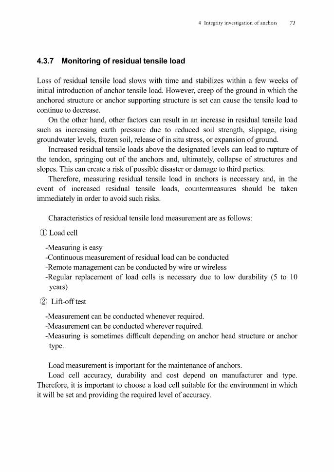
4.3.7 Monitoring of residual tensile load Loss of residual tensile load slows with time and stabilizes within a few weeks of initial introduction of anchor tensile load. However, creep of the ground in which the anchored structure or anchor supporting structure is set can cause the tensile load to continue to decrease.
On the other hand, other factors can result in an increase in residual tensile load such as increasing earth pressure due to reduced soil strength, slippage, rising groundwater levels, frozen soil, release of in situ stress, or expansion of ground.
Increased residual tensile loads above the designated levels can lead to rupture of the tendon, springing out of the anchors and, ultimately, collapse of structures and slopes. This can create a risk of possible disaster or damage to third parties.
Therefore, measuring residual tensile load in anchors is necessary and, in the event of increased residual tensile loads, countermeasures should be taken immediately in order to avoid such risks.
Characteristics of residual tensile load measurement are as follows:
① Load cell
-Measuring is easy -Continuous measurement of residual load can be conducted -Remote management can be conducted by wire or wireless -Regular replacement of load cells is necessary due to low durability (5 to 10 years)
② Lift-off test
-Measurement can be conducted whenever required. -Measurement can be conducted wherever required. -Measuring is sometimes difcult depending on anchor head structure or anchor type.
Load measurement is important for the maintenance of anchors. Load cell accuracy, durability and cost depend on manufacturer and type.
Therefore, it is important to choose a load cell suitable for the environment in which it will be set and providing the required level of accuracy.
4 Integrity investigation of anchors 71
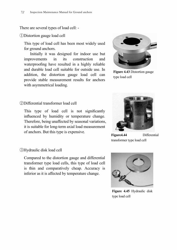
There are several types of load cell: -
①Distortion gauge load cell
This type of load cell has been most widely used for ground anchors.
Initially it was designed for indoor use but improvements in its construction and waterproong have resulted in a highly reliable and durable load cell suitable for outside use. In addition, the distortion gauge load cell can provide stable measurement results for anchors with asymmetrical loading.
②Differential transformer load cell
This type of load cell is not signicantly inuenced by humidity or temperature change. Therefore, being unaffected by seasonal variations, it is suitable for long-term axial load measurement of anchors. But this type is expensive.
③Hydraulic disk load cell
Compared to the distortion gauge and differential transformer type load cells, this type of load cell is thin and comparatively cheap. Accuracy is inferior as it is affected by temperature change.
Figure 4.43 Distortion gauge type load cell
Figure4.44 Differential transformer type load cell
Figure 4.45 Hydraulic disk type load cell
Inspection Maintenance Manual for Ground anchors72

4.3.8 Ultrasonic flaw test (1) Principle
The ultrasonic aw test is a technique to detect aws in a specimen by sending and receiving short ultrasonic pulse waves.
The ultrasonic pulses will be reected when encountering aws and it is possible to identify the position of the aw by observing the period elapsing between transmitting and receiving the ultrasonic pulse.
Figure 4.46 is a view showing an application of the principle to integrity investigation of anchor tendons.
Figure 4.46 Application of the principle to integrity investigation of anchor tendons
Figure 4.47 A practical observation
4 Integrity investigation of anchors 73
(2) Evaluation Many variables, such as anchor type, structure and site conditions, can affect the results produced by the ultrasonic aw test. Therefore, it may be difcult to evaluate the integrity of anchors based solely on the results of the ultrasonic aw test. So, it is desirable to evaluate the integrity comprehensively with the result of the lift-off test or performance conrmation test.
(3) Accuracy
The accuracy of nondestructive tests such as the ultrasonic aw test are greatly inuenced by operator skill. Therefore, it is preferable that only certied engineers having undertaken training and successfully passed a qualifying examination conduct the ultrasonic aw test.
Inspection Maintenance Manual for Ground anchors74
5 Countermeasures for anchors
5.1 Basic concept of countermeasures
A variety of countermeasures can be implemented. Their selection should be based upon the ndings of the integrity investigation. Countermeasures include durability improvement, repair and reinforcement, renewal, emergency countermeasures and temporary countermeasures.
If, at the time of investigation, anchors have deteriorated to below the level required for service, or are likely to suffer from performance deterioration to below the level required for service, countermeasures should be implemented to ensure performance requirements during their service life.
For anchors that are judged to be performing satisfactorily, consideration shall be given to implementing countermeasures in order to extend the service life.
When repair or reinforcement countermeasures are newly planned, an appropriate method shall be selected by evaluating recent performance data and actual behavior, without necessarily referring to the original design data.
A combination of methods and countermeasures are considered whenever necessary. It is possible that an anchor integrity problem could highlight the fact that the original anchor installation and/or design was inadequate or unsuitable. Suitability and adequacy of anchors should therefore always be carefully examined when countermeasures are being considered.
While anchor integrity investigations are conducted on each anchor individually, the possibility of implementing common countermeasures as a whole should be considered as common causes of deterioration of anchor or anchored structure can often be identied. Furthermore, countermeasures may not necessarily be implemented directly to the anchors themselves.
In the case that an anchored slope has a problem, consideration shall be given to the possibility of removing the cause of the problem before implementing countermeasures on the anchors. If such causes cannot be removed, the adequacy of the anchor works should be examined.
5 Countermeasures for anchors 75
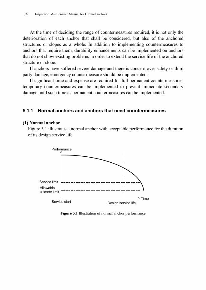
At the time of deciding the range of countermeasures required, it is not only the deterioration of each anchor that shall be considered, but also of the anchored structures or slopes as a whole. In addition to implementing countermeasures to anchors that require them, durability enhancements can be implemented on anchors that do not show existing problems in order to extend the service life of the anchored structure or slope.
If anchors have suffered severe damage and there is concern over safety or third party damage, emergency countermeasure should be implemented.
If signicant time and expense are required for full permanent countermeasures, temporary countermeasures can be implemented to prevent immediate secondary damage until such time as permanent countermeasures can be implemented. 5.1.1 Normal anchors and anchors that need countermeasures (1) Normal anchor
Figure 5.1 illustrates a normal anchor with acceptable performance for the duration of its design service life.
Figure 5.1 Illustration of normal anchor performance
Design service lifeService start Time
Allowable ultimate limit
Service limit
Performance
Inspection Maintenance Manual for Ground anchors76
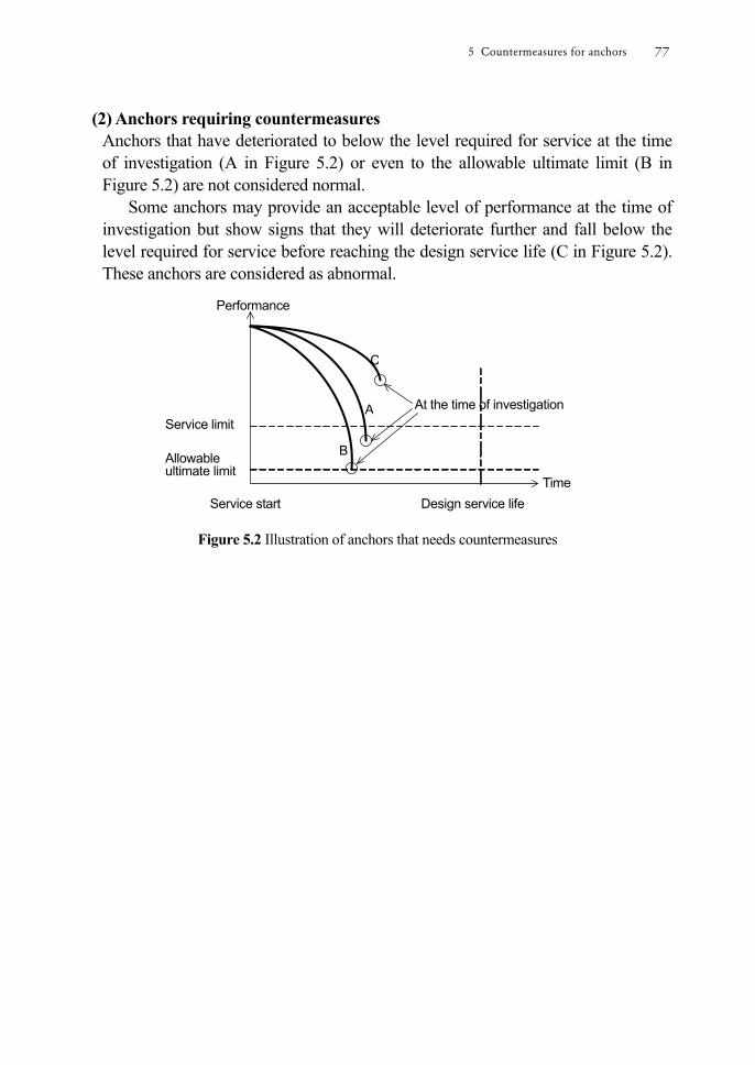
(2) Anchors requiring countermeasures Anchors that have deteriorated to below the level required for service at the time of investigation (A in Figure 5.2) or even to the allowable ultimate limit (B in Figure 5.2) are not considered normal.
Some anchors may provide an acceptable level of performance at the time of investigation but show signs that they will deteriorate further and fall below the level required for service before reaching the design service life (C in Figure 5.2). These anchors are considered as abnormal.
Figure 5.2 Illustration of anchors that needs countermeasures
Design service lifeService start Time
Performance
At the time of investigation A
B
C
Service limit
Allowable ultimate limit
5 Countermeasures for anchors 77
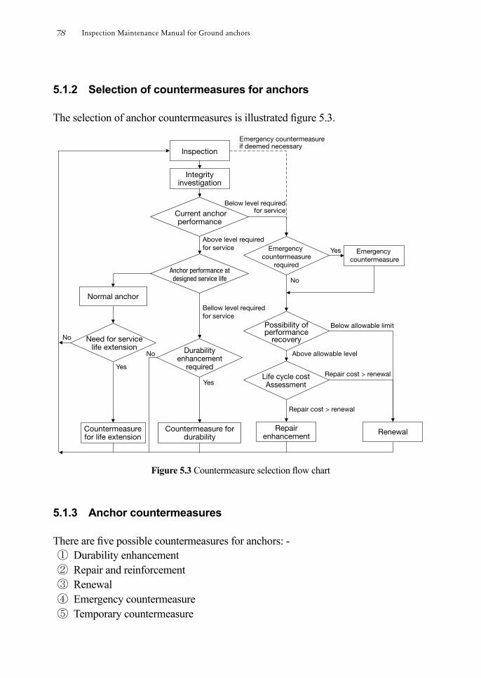
5.1.2 Selection of countermeasures for anchors The selection of anchor countermeasures is illustrated gure 5.3.
Figure 5.3 Countermeasure selection ow chart
5.1.3 Anchor countermeasures There are ve possible countermeasures for anchors: - ① Durability enhancement ② Repair and reinforcement ③ Renewal ④ Emergency countermeasure ⑤ Temporary countermeasure
Inspection Maintenance Manual for Ground anchors78
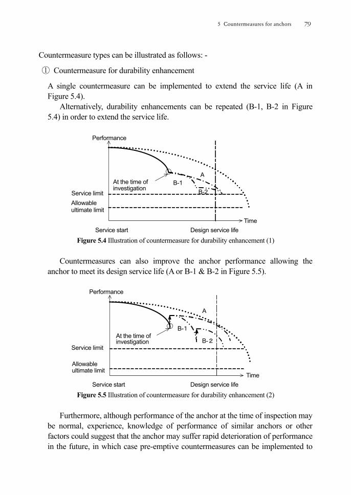
Countermeasure types can be illustrated as follows: -
① Countermeasure for durability enhancement
A single countermeasure can be implemented to extend the service life (A in Figure 5.4).
Alternatively, durability enhancements can be repeated (B-1, B-2 in Figure 5.4) in order to extend the service life.
Figure 5.4 Illustration of countermeasure for durability enhancement (1)
Countermeasures can also improve the anchor performance allowing the
anchor to meet its design service life (A or B-1 & B-2 in Figure 5.5).
Figure 5.5 Illustration of countermeasure for durability enhancement (2)
Furthermore, although performance of the anchor at the time of inspection may
be normal, experience, knowledge of performance of similar anchors or other factors could suggest that the anchor may suffer rapid deterioration of performance in the future, in which case pre-emptive countermeasures can be implemented to
Design service lifeService start Time
A
B-1
B-2At the time of investigation
Service limit
Allowable ultimate limit
Design service lifeService start Time
Performance
Service limit
AB-1
B-2 At the time of investigation
Allowable ultimate limit
Performance
5 Countermeasures for anchors 79
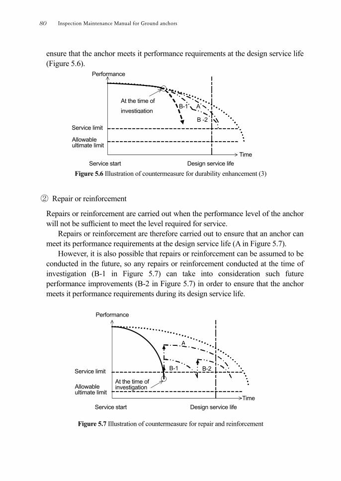
ensure that the anchor meets it performance requirements at the design service life (Figure 5.6).
Figure 5.6 Illustration of countermeasure for durability enhancement (3)
② Repair or reinforcement
Repairs or reinforcement are carried out when the performance level of the anchor will not be sufcient to meet the level required for service.
Repairs or reinforcement are therefore carried out to ensure that an anchor can meet its performance requirements at the design service life (A in Figure 5.7).
However, it is also possible that repairs or reinforcement can be assumed to be conducted in the future, so any repairs or reinforcement conducted at the time of investigation (B-1 in Figure 5.7) can take into consideration such future performance improvements (B-2 in Figure 5.7) in order to ensure that the anchor meets it performance requirements during its design service life.
Figure 5.7 Illustration of countermeasure for repair and reinforcement
Design service lifeService start Time
At the time of investigation
B-1 B-2
A
Allowable ultimate limit
Service limit
Design service lifeService start Time
Performance
Service limit
At the time of
investigationA B-1
B -2
Allowable ultimate limit
Performance
Inspection Maintenance Manual for Ground anchors80

③ Renewal
When anchor performance is below the level required for service at the time of investigation and it is difcult to recover performance by repair and reinforcement due to technical constraints, or would be disadvantageous in terms of cost or construction time, new anchors can be installed (Figure 5.8).
Figure 5.8 Illustration of countermeasure for renewal
④ Emergency countermeasure
When anchor performance, or performance of the anchored structures or slopes, has fallen below the minimum requirement for service at the time of investigation, an emergency countermeasure is implemented to prevent third party damage (Figure 5.9).
Figure 5.9 Illustration of emergency countermeasure
Design service lifeService start
Performance
Allowable ultimate limit
Service limit
At the time of investigation
Time
Design service life Service start Time
At the time of investigation Allowable
ultimate limit
Service limit
Implementation of other countermeasure after emergency countermeasure
Performance
5 Countermeasures for anchors 81
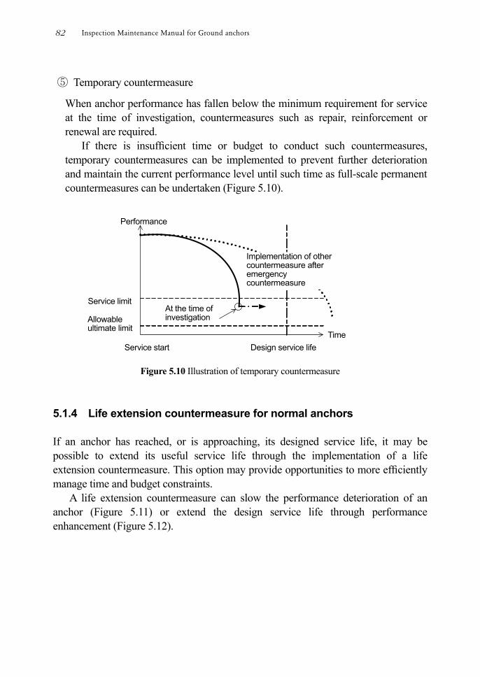
⑤ Temporary countermeasure
When anchor performance has fallen below the minimum requirement for service at the time of investigation, countermeasures such as repair, reinforcement or renewal are required.
If there is insufcient time or budget to conduct such countermeasures, temporary countermeasures can be implemented to prevent further deterioration and maintain the current performance level until such time as full-scale permanent countermeasures can be undertaken (Figure 5.10).
Figure 5.10 Illustration of temporary countermeasure
5.1.4 Life extension countermeasure for normal anchors If an anchor has reached, or is approaching, its designed service life, it may be possible to extend its useful service life through the implementation of a life extension countermeasure. This option may provide opportunities to more efciently manage time and budget constraints.
A life extension countermeasure can slow the performance deterioration of an anchor (Figure 5.11) or extend the design service life through performance enhancement (Figure 5.12).
Design service lifeService start Time
Performance
At the time of investigation Allowable
ultimate limit
Service limit
Implementation of other countermeasure after emergency countermeasure
Inspection Maintenance Manual for Ground anchors82
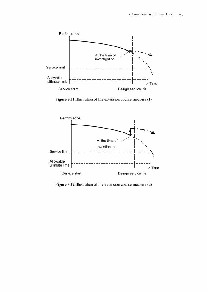
Figure 5.11 Illustration of life extension countermeasure (1)
Figure 5.12 Illustration of life extension countermeasure (2)
Design service life Service start Time
At the time of investigation
Allowable ultimate limit
Service limit
Design service life Service start Time
At the time of investigation
Allowable ultimate limit
Service limit
Performance
Performance
5 Countermeasures for anchors 83
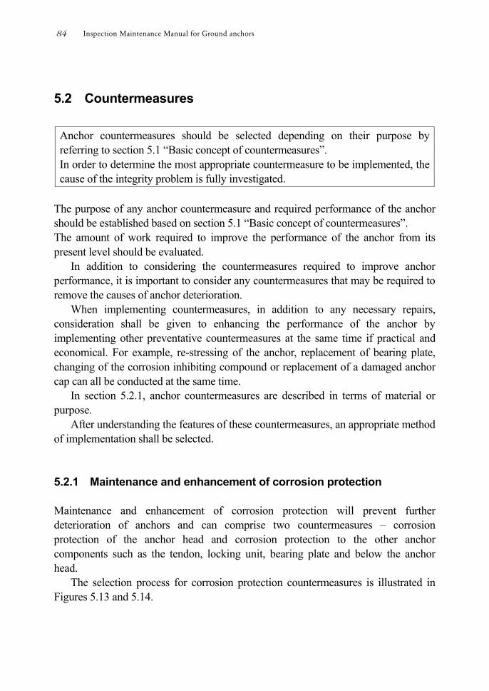
5.2 Countermeasures
Anchor countermeasures should be selected depending on their purpose by referring to section 5.1 “Basic concept of countermeasures”. In order to determine the most appropriate countermeasure to be implemented, the cause of the integrity problem is fully investigated.
The purpose of any anchor countermeasure and required performance of the anchor should be established based on section 5.1 “Basic concept of countermeasures”. The amount of work required to improve the performance of the anchor from its present level should be evaluated.
In addition to considering the countermeasures required to improve anchor performance, it is important to consider any countermeasures that may be required to remove the causes of anchor deterioration.
When implementing countermeasures, in addition to any necessary repairs, consideration shall be given to enhancing the performance of the anchor by implementing other preventative countermeasures at the same time if practical and economical. For example, re-stressing of the anchor, replacement of bearing plate, changing of the corrosion inhibiting compound or replacement of a damaged anchor cap can all be conducted at the same time.
In section 5.2.1, anchor countermeasures are described in terms of material or purpose.
After understanding the features of these countermeasures, an appropriate method of implementation shall be selected. 5.2.1 Maintenance and enhancement of corrosion protection Maintenance and enhancement of corrosion protection will prevent further deterioration of anchors and can comprise two countermeasures – corrosion protection of the anchor head and corrosion protection to the other anchor components such as the tendon, locking unit, bearing plate and below the anchor head.
The selection process for corrosion protection countermeasures is illustrated in Figures 5.13 and 5.14.
Inspection Maintenance Manual for Ground anchors84
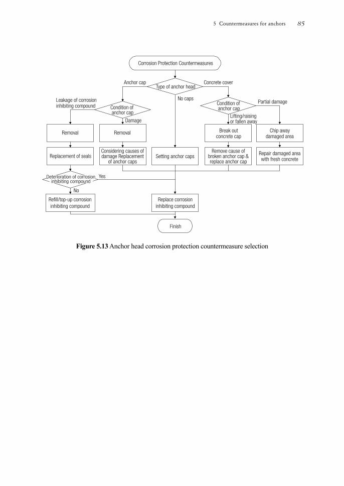
Figure 5.13 Anchor head corrosion protection countermeasure selection
5 Countermeasures for anchors 85
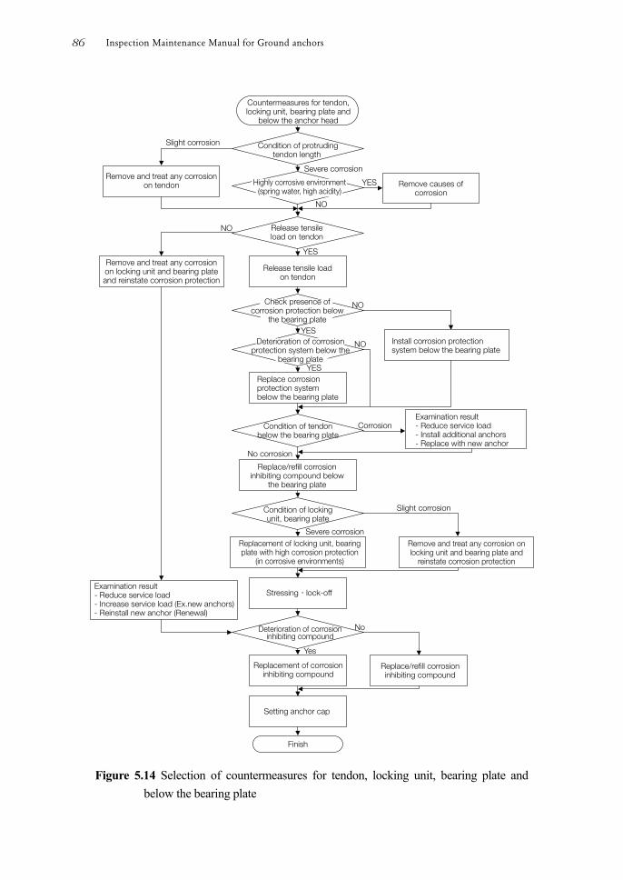
Figure 5.14 Selection of countermeasures for tendon, locking unit, bearing plate and
below the bearing plate
Inspection Maintenance Manual for Ground anchors86
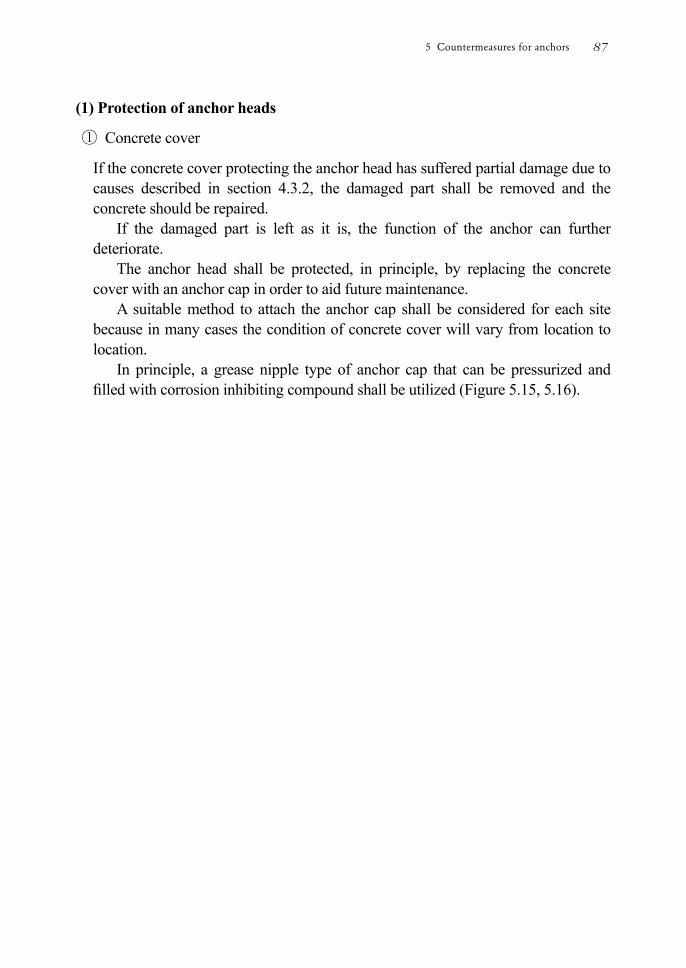
(1) Protection of anchor heads
① Concrete cover
If the concrete cover protecting the anchor head has suffered partial damage due to causes described in section 4.3.2, the damaged part shall be removed and the concrete should be repaired.
If the damaged part is left as it is, the function of the anchor can further deteriorate.
The anchor head shall be protected, in principle, by replacing the concrete cover with an anchor cap in order to aid future maintenance.
A suitable method to attach the anchor cap shall be considered for each site because in many cases the condition of concrete cover will vary from location to location.
In principle, a grease nipple type of anchor cap that can be pressurized and lled with corrosion inhibiting compound shall be utilized (Figure 5.15, 5.16).
5 Countermeasures for anchors 87

Figure 5.15 Examples of repair of anchor head (Setting anchor cap)
① Setting hole-in anchor ② Setting plate for fixings
③ Setting seals ④ Setting plate for anchor cap
⑤ Setting anchor cap
⑦ Sealing around anchor head
⑥ Filling corrosion inhibiting compound
⑧ Finish
Inspection Maintenance Manual for Ground anchors88
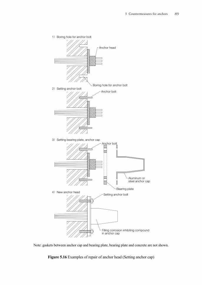
Note: gaskets between anchor cap and bearing plate, bearing plate and concrete are not shown.
Figure 5.16 Examples of repair of anchor head (Setting anchor cap)
5 Countermeasures for anchors 89
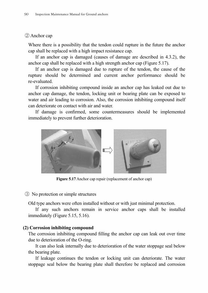
② Anchor cap
Where there is a possibility that the tendon could rupture in the future the anchor cap shall be replaced with a high impact resistance cap.
If an anchor cap is damaged (causes of damage are described in 4.3.2), the anchor cap shall be replaced with a high strength anchor cap (Figure 5.17).
If an anchor cap is damaged due to rupture of the tendon, the cause of the rupture should be determined and current anchor performance should be re-evaluated.
If corrosion inhibiting compound inside an anchor cap has leaked out due to anchor cap damage, the tendon, locking unit or bearing plate can be exposed to water and air leading to corrosion. Also, the corrosion inhibiting compound itself can deteriorate on contact with air and water.
If damage is conrmed, some countermeasures should be implemented immediately to prevent further deterioration.
Figure 5.17 Anchor cap repair (replacement of anchor cap)
③ No protection or simple structures
Old type anchors were often installed without or with just minimal protection. If any such anchors remain in service anchor caps shall be installed
immediately (Figure 5.15, 5.16). (2) Corrosion inhibiting compound
The corrosion inhibiting compound lling the anchor cap can leak out over time due to deterioration of the O-ring.
It can also leak internally due to deterioration of the water stoppage seal below the bearing plate.
If leakage continues the tendon or locking unit can deteriorate. The water stoppage seal below the bearing plate shall therefore be replaced and corrosion
Inspection Maintenance Manual for Ground anchors90
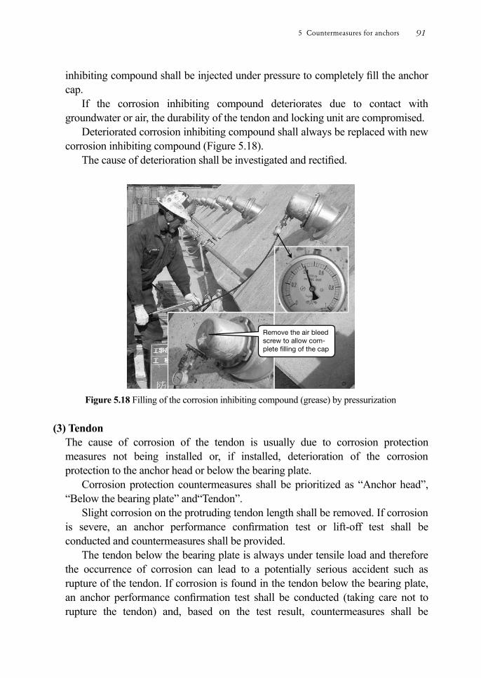
inhibiting compound shall be injected under pressure to completely ll the anchor cap.
If the corrosion inhibiting compound deteriorates due to contact with groundwater or air, the durability of the tendon and locking unit are compromised.
Deteriorated corrosion inhibiting compound shall always be replaced with new corrosion inhibiting compound (Figure 5.18).
The cause of deterioration shall be investigated and rectied.
Figure 5.18 Filling of the corrosion inhibiting compound (grease) by pressurization
(3) Tendon
The cause of corrosion of the tendon is usually due to corrosion protection measures not being installed or, if installed, deterioration of the corrosion protection to the anchor head or below the bearing plate.
Corrosion protection countermeasures shall be prioritized as “Anchor head”, “Below the bearing plate” and“Tendon”.
Slight corrosion on the protruding tendon length shall be removed. If corrosion is severe, an anchor performance conrmation test or lift-off test shall be conducted and countermeasures shall be provided.
The tendon below the bearing plate is always under tensile load and therefore the occurrence of corrosion can lead to a potentially serious accident such as rupture of the tendon. If corrosion is found in the tendon below the bearing plate, an anchor performance conrmation test shall be conducted (taking care not to rupture the tendon) and, based on the test result, countermeasures shall be
5 Countermeasures for anchors 91
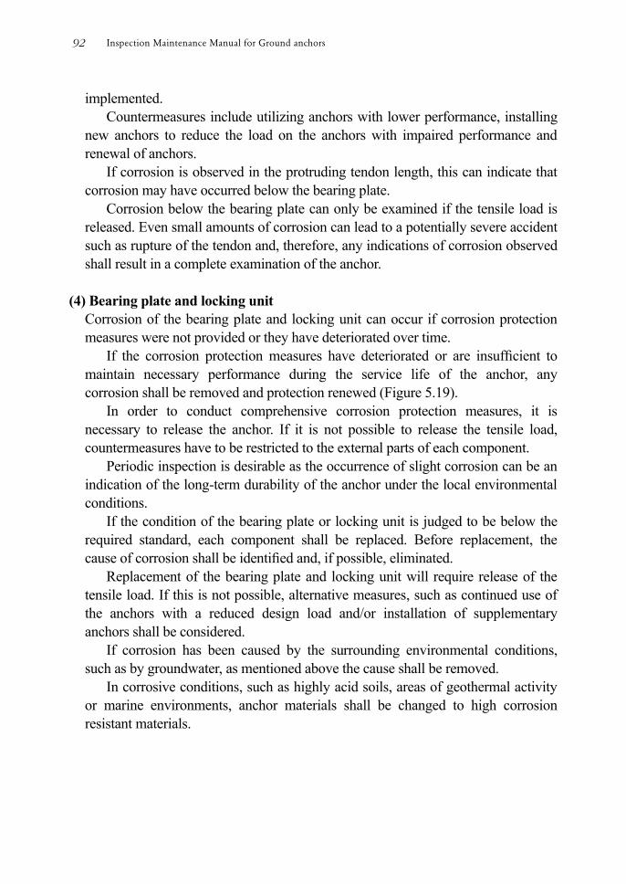
implemented. Countermeasures include utilizing anchors with lower performance, installing
new anchors to reduce the load on the anchors with impaired performance and renewal of anchors.
If corrosion is observed in the protruding tendon length, this can indicate that corrosion may have occurred below the bearing plate.
Corrosion below the bearing plate can only be examined if the tensile load is released. Even small amounts of corrosion can lead to a potentially severe accident such as rupture of the tendon and, therefore, any indications of corrosion observed shall result in a complete examination of the anchor.
(4) Bearing plate and locking unit
Corrosion of the bearing plate and locking unit can occur if corrosion protection measures were not provided or they have deteriorated over time.
If the corrosion protection measures have deteriorated or are insufcient to maintain necessary performance during the service life of the anchor, any corrosion shall be removed and protection renewed (Figure 5.19).
In order to conduct comprehensive corrosion protection measures, it is necessary to release the anchor. If it is not possible to release the tensile load, countermeasures have to be restricted to the external parts of each component.
Periodic inspection is desirable as the occurrence of slight corrosion can be an indication of the long-term durability of the anchor under the local environmental conditions.
If the condition of the bearing plate or locking unit is judged to be below the required standard, each component shall be replaced. Before replacement, the cause of corrosion shall be identied and, if possible, eliminated.
Replacement of the bearing plate and locking unit will require release of the tensile load. If this is not possible, alternative measures, such as continued use of the anchors with a reduced design load and/or installation of supplementary anchors shall be considered.
If corrosion has been caused by the surrounding environmental conditions, such as by groundwater, as mentioned above the cause shall be removed.
In corrosive conditions, such as highly acid soils, areas of geothermal activity or marine environments, anchor materials shall be changed to high corrosion resistant materials.
Inspection Maintenance Manual for Ground anchors92
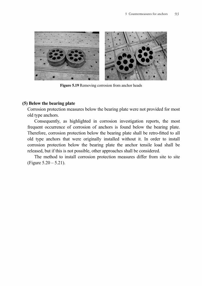
Figure 5.19 Removing corrosion from anchor heads (5) Below the bearing plate
Corrosion protection measures below the bearing plate were not provided for most old type anchors.
Consequently, as highlighted in corrosion investigation reports, the most frequent occurrence of corrosion of anchors is found below the bearing plate. Therefore, corrosion protection below the bearing plate shall be retro-tted to all old type anchors that were originally installed without it. In order to install corrosion protection below the bearing plate the anchor tensile load shall be released, but if this is not possible, other approaches shall be considered.
The method to install corrosion protection measures differ from site to site (Figure 5.20 – 5.21).
5 Countermeasures for anchors 93
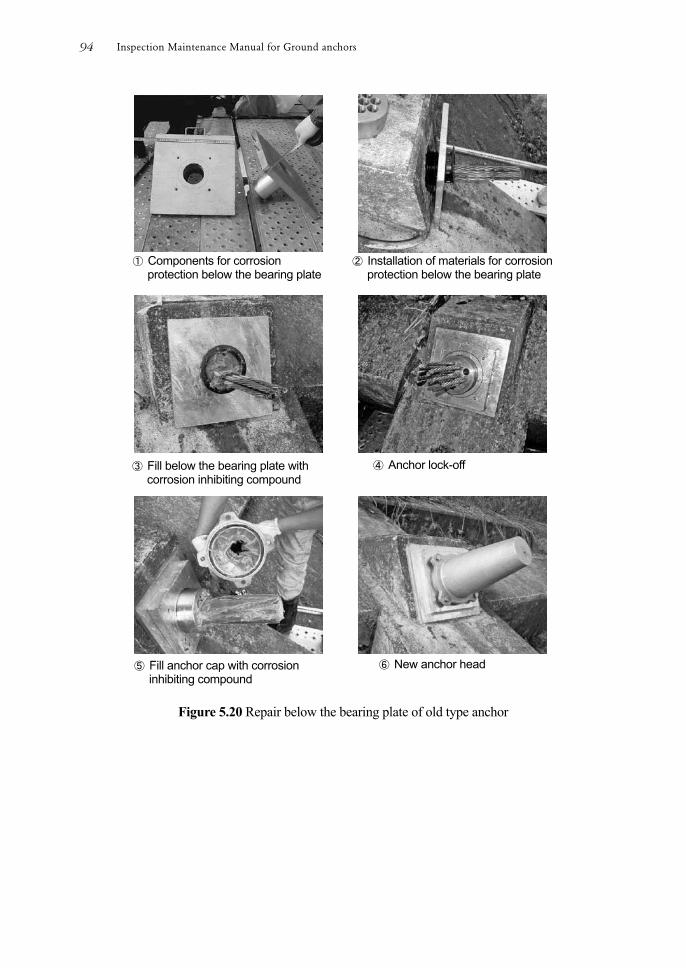
Figure 5.20 Repair below the bearing plate of old type anchor
① Components for corrosion protection below the bearing plate
② Installation of materials for corrosion protection below the bearing plate
③ Fill below the bearing plate with corrosion inhibiting compound
④ Anchor lock-off
⑤ Fill anchor cap with corrosion inhibiting compound
⑥ New anchor head
Inspection Maintenance Manual for Ground anchors94
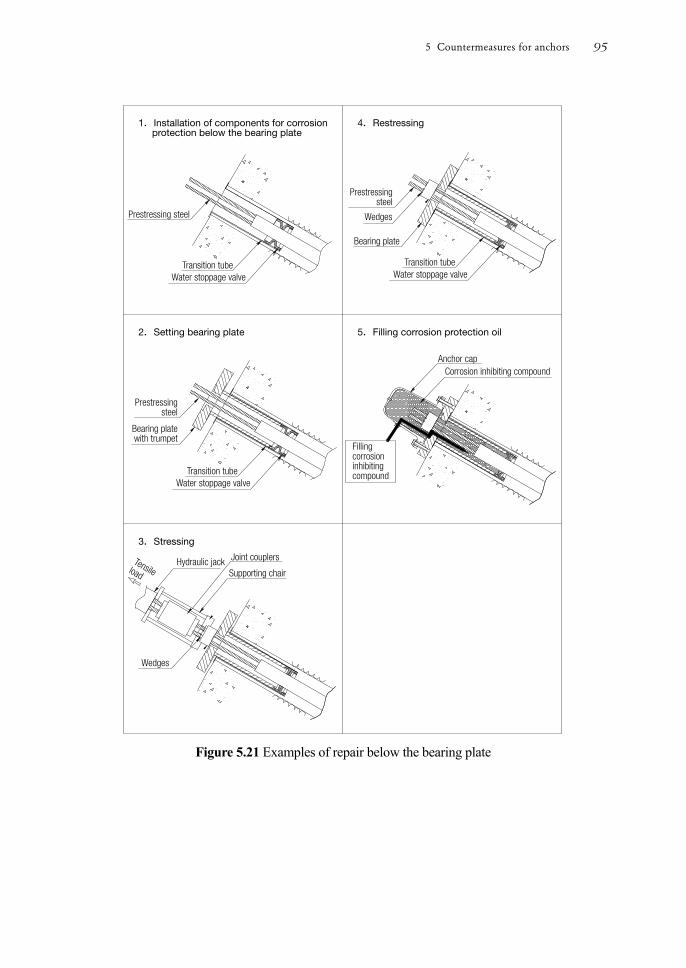
Figure 5.21 Examples of repair below the bearing plate
5 Countermeasures for anchors 95
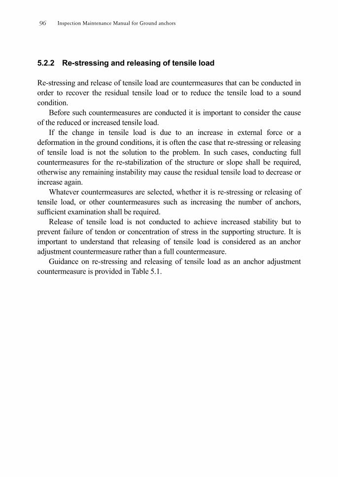
5.2.2 Re-stressing and releasing of tensile load Re-stressing and release of tensile load are countermeasures that can be conducted in order to recover the residual tensile load or to reduce the tensile load to a sound condition.
Before such countermeasures are conducted it is important to consider the cause of the reduced or increased tensile load.
If the change in tensile load is due to an increase in external force or a deformation in the ground conditions, it is often the case that re-stressing or releasing of tensile load is not the solution to the problem. In such cases, conducting full countermeasures for the re-stabilization of the structure or slope shall be required, otherwise any remaining instability may cause the residual tensile load to decrease or increase again.
Whatever countermeasures are selected, whether it is re-stressing or releasing of tensile load, or other countermeasures such as increasing the number of anchors, sufcient examination shall be required.
Release of tensile load is not conducted to achieve increased stability but to prevent failure of tendon or concentration of stress in the supporting structure. It is important to understand that releasing of tensile load is considered as an anchor adjustment countermeasure rather than a full countermeasure.
Guidance on re-stressing and releasing of tensile load as an anchor adjustment countermeasure is provided in Table 5.1.
Inspection Maintenance Manual for Ground anchors96
Table 5.1 Guidance on re-stressing and releasing of tensile load
① Structure of anchor locking units
Anchor locking units are considered to fall into one of three types as shown in Table 5.2, each of them having different requirements for re-stressing and releasing of tensile load.
The “Nut” type and “Wedge” type are the anchor locking units that allow both re-stressing and releasing of tensile load. It is necessary to establish if there is sufcient threaded protruding length to allow release of tensile load.
The “Wedge + Threaded Barrel” type locking unit usually has insufcient
Item Situation Causes Anchor adjustment Remarks
Residual Tensile Load
Loss
Deterioration of tendon
Re-stressing after assessment of the allowable pull-out load from the results of the performance conrmation test
Any corrosion or damage to the tendon should be taken into consideration to ensure that the tendon does not break during re-stressing.
Changes in ground conditions
Re-stressing after examination and understanding the creep characteristics of the ground
Exchanging of the locking unit to one that facilitates simple re-stressing is desirable as it is likely that further re-stressing will be necessary in the future.
Subsidence or deterioration of structures
Re-stressing after removing or correcting the cause of the subsidence or deterioration
The tensile load of the anchor will depend on the strength of the ground supporting the structure
Gain
External force greater than design load
Partial release after examination of the stability of the structure or, if necessary, the whole slope.
Take particular care when releasing if residual tensile load is almost allowable pull-out load.
Frost heave of supported slope or rock
Exchange the head structure to one that can resist deformation by frost heave
When de-stressing is possible
5 Countermeasures for anchors 97

protruding length available to allow release of tensile load and re-stressing may only be possible if the protruding tendon that may exist has sufcient length to which a jack or coupler may be attached.
If possible, it is preferable to exchange the locking unit to a type suitable for future re-stressing or releasing of tensile load. In this case, it will be necessary to completely release the tensile load of the anchor during the exchange of the locking unit (refer to 4.3.4).
Table 5.2 Requirement for re-stressing and releasing of anchor locking unit
Locking unit type
Requirement for Re-stressing or Releasing
Suitability Re-stressing Releasing
Nut type
Surplus threaded protruding length is required to attach a coupler for the tension bar when re-stressing. Additional length is also required to allow the tendon to pass through the nut when releasing
◎ ◎
Wedge type
The protruding tendon length must be sufcient to attach the jack set or to attach a joint coupler. Additional protruding length is required for releasing.
○ △
Wedge + Threaded Barrel type
Surplus threaded protruding length is required to attach a coupler to re-stress the tendon. Additional length is also required to pass through the nut when releasing.
◎ ○
Note: ◎ high ○ medium △low
② Corroded or damaged tendon
If tendons are corroded or damaged the allowable tensile load is reduced, increasing the risk of rupture during re-stressing or releasing tensile load.
The current anchor performance shall be re-evaluated by conducting an anchor performance conrmation test. The results of the anchor performance conrmation test shall be used to plan and examine options for re-stressing or releasing of tensile load or to renew the anchor or to continue utilization at reduced function.
Having re-evaluated the anchor performance and taken the decision to proceed with re-stressing or release of tensile load, consideration has to be given to the method of re-stressing or release of tensile load. In order to re-stress or release the tensile load, it is rst necessary to conduct a lift-off test.
Inspection Maintenance Manual for Ground anchors98
The result of the lift-off test can conrm the residual tensile load and data can be collected for reference during future maintenance.
③ Method of re-stressing or releasing tensile load
As mentioned above, when de-stressing, re-stressing or releasing tensile load there is a risk of rupture to the tendon. Therefore, after conrming whether the tendon is sound, the method of re-stressing or releasing the tensile load shall be considered carfully.
The anchor head shall be protected against damage and the area around the anchor head shall be kept clear when de-stressing, re-stressing or releasing is carried out.
5 Countermeasures for anchors 99
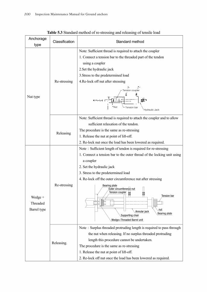
Table 5.3 Standard method of re-stressing and releasing of tensile load Anchorage
type Classification Standard method
Nut type
Re-stressing
Note: Sufcient thread is required to attach the coupler 1. Connect a tension bar to the threaded part of the tendon using a coupler 2.Set the hydraulic jack 3.Stress to the predetermined load 4.Re-lock off nut after stressing
Releasing
Note: Sufcient thread is required to attach the coupler and to allow sufcient relaxation of the tendon.
The procedure is the same as re-stressing 1. Release the nut at point of lift-off. 2. Re-lock nut once the load has been lowered as required.
Wedge + Threaded
Barrel type
Re-stressing
Note:Sufcient length of tendon is required for re-stressing 1. Connect a tension bar to the outer thread of the locking unit using
a coupler 2. Set the hydraulic jack 3. Stress to the predetermined load 4. Re-lock off the outer circumference nut after stressing
Releasing.
Note:Surplus threaded protruding length is required to pass through the nut when releasing. If no surplus threaded protruding length this procedure cannot be undertaken.
The procedure is the same as re-stressing 1. Release the nut at point of lift-off. 2. Re-lock off nut once the load has been lowered as required.
Inspection Maintenance Manual for Ground anchors100
5.2.3 Renewal
If an integrity investigation identies an integrity problem in an anchor, an appropriate countermeasure should be implemented to repair or reinforce the anchor. However, repair or reinforcement of most old-type anchors is difcult.
If the anchor cannot be de-stressed, repair or reinforcement below the bearing plate or to the tendon is impossible. In this case, progressive corrosion will increase the risk of rupture of the tendon and emergency and/or temporary countermeasures should be taken in order to mitigate the risk. Increasing the number of anchors and renewal of anchors should be considered.
If an anchor performance conrmation test does determine that the allowable tensile load of the anchor is below the design load, the anchor should be re-evaluated and anchor renewal or increasing the number of anchors should be considered. Increasing the number of anchors and renewal of anchors should be considered if the stability conditions have deteriorated through variation of external forces, such as increased groundwater level and slippage load. Increasing the number of anchors can compensate for reducing the loading on the existing anchors.
The decision to renew or increase the number of anchors is based on the
following: -
① Re-evaluation of the function of existing anchors.
The allowable tensile load of existing anchors is reviewed based on the results of anchor performance conrmation tests. A re-evaluation is carried out of the function that can be expected from the anchor once necessary repairs and reinforcement are conducted.
② Comparison and review of life cycle cost of repair, reinforcement, and increasing
the number of anchors, renewal.
A comparison of life cycle costs is made for the case of maintaining existing anchors by repair and/or reinforcement, the case of increasing the number of casting anchors and the case of renewal of anchors.
③ Review of stability of structures and slopes as a whole
The present stability of the structure or slops as a whole is reviewed and the
5 Countermeasures for anchors 101
anchors are redesigned if necessary.
④ Review during installation
The inuence on existing structures by the renewal or replacement of anchors is reviewed.
5.3 Emergency countermeasures
For anchors that are judged to be at risk of rupture of the tendon due to increased residual tensile load resulting from changing ground conditions or the deformation of other structures in the vicinity, countermeasures shall be considered and appropriate emergency countermeasures shall be provided.
For anchors that are judged to be at risk of rupture of the tendon, appropriate emergency countermeasures shall be conducted to prevent third party harm or damage.
If a tendon does rupture, and particularly if the rupture occurs in the free anchor length or at the boundary of the free and xed anchor length, a great amount of kinetic energy is released through the anchor head, and the tendon can spring out from the anchored structure or slope into the air. Furthermore, the concrete cover, anchor cap or locking unit can drop off and fall away.
The results of tendon rupture can be dangerous to third parties so countermeasures to protect against springing out or falling anchor heads and/or caps shall be conducted immediately.
Countermeasures for anchors that are judged to be dangerous vary, depending on the degree of danger. But generally, a tendon rupture caused by corrosion could occur suddenly, it is difcult to judge the risk. Therefore causes of rupture shall be investigated and, together with information collected during daily inspections, used to assess risks.
If anchors have an increased risk of rupture due to aging after many years of service, or have a history of rupture and springing out causing falling anchor heads or caps, the xing of a metal plate at the anchor head or covering of the structures or slopes with wire netting to absorb the kinetic energy can be considered.
The method or scale of countermeasures is decided on a case by case basis depending on the site situation.
If other external forces threaten to rupture anchor tendons, countermeasures shall be considered to be applied not to the anchors, but directly to the threat itself such as
Inspection Maintenance Manual for Ground anchors102
by placement of counterweight ll, supporting with sandbags or soil removal work. If rising groundwater levels threaten to cause ruptured anchor tendons, drainage
boring as an emergency countermeasure relieves the increased pressure.
5.4 Temporary countermeasures
In case that time and expense are required for full-scale countermeasures, temporary countermeasures can be provided to prevent immediate deterioration of performance until such time that permanent maintenance can be conducted more economically or conveniently.
As mentioned in 5.1, the need for countermeasures for anchors is a technical decision comparing the actual level of anchor function to the required level of anchor function. However, in practice, countermeasures are inuenced by various non-technical factors.
It may therefore be necessary to consider temporary countermeasures to maintain current function or to prevent further deterioration. For example, seasonal weather conditions or disruption to transportation systems due to natural disasters could make it necessary to delay implementing full-scale countermeasures.
It may be the case that countermeasures could be implemented at a later date to coincide with other related construction work.
Under such circumstances, if provided properly, temporary countermeasures can offer safe and economical alternatives with less impact on the local environment. However, careful planning is required for implementation as in addition to technical factors, other factors such as economic, logistical and local-needs should be considered.
When planning temporary countermeasures the following points shall be considered: -
① Temporary countermeasures are not permanent countermeasures and can only be considered as countermeasures for the time being. It is particularly important to dene the period of time over which the temporary countermeasures are expected to maintain anchor function and, if possible, specify when permanent countermeasures shall be implemented.
② Temporary countermeasures should not involve any risk of danger to third parties.
If there is a risk of danger to third parties, emergency countermeasures should be
5 Countermeasures for anchors 103
provided at rst and then the planning of temporary countermeasures should be considered.
Inspection Maintenance Manual for Ground anchors104
Closing remarks Problems and countermeasures based on maintenance of ground anchors
“International Conference on Ground Anchorages and Anchored Structures in Service 2007” was held for the first time in the world at ice (Institution Civil Engineers) in November 2007.
The purpose of this conference was to share information of technology, standard and case histories on inspection, integrity investigation, monitoring and countermeasures of existing anchors.
The information was scarce and was not systemized yet. Ground anchors were applied to the enforcing and rising of Cheurfas Dam in
Algeria for the first time in the world. In Japan More than 50 years have passed since ground anchors were applied to stabilization for secondly dam of Fujiwara Dam.But ground anchors seldom became objective for inspection and maintenance.
Damages or malfunction of ground anchors had been reported since the middle of 1970’s. Therefore, FIP or Fédération Internationale de la Précontrainte (Currently: fib) established working sessions of ground anchors and the investigation of existing anchors was carried out under the direction of Prof. G. S. Littlejohn who was the chairman for International Conference on Ground Anchorages and Anchored Structures in Service 2007. AS a result the recommended specification for permanent application of ground anchors was presented in 1986.
The standard (JSF Standard: D1-88) of Japanese Society of Soil Mechanics and Foundation Engineering (Currently: The Japanese Geotechnical Society) was normalize, obligation for double corrosion protection under that specification. Therefore the anchors constructed before this standard might have some problems in durability, it was necessary to conduct the inspection, the improvement of durability by maintenance and the extension of service life.
Under these circumstances, the necessity and importance of maintenance of anchors have been highly focused; however, the history was short. “Maintenance manual for Ground anchors” was compiled with fewer academic reports and report of the site in the world.
It took 6 years to compile “Maintenance manual for ground anchors” and during that time, documents about various existing anchors were collected, and investigation
6 Closing remarks 105
and inspection at sites were conducted for understanding the conditions of existing anchors. Furthermore, the integrity investigation, countermeasures and monitoring were conducted in some fields including monitoring of anchor head and anchor below the bearing plate, and decrease and deterioration of corrosion inhibiting compound influenced by unsufficient corrosion protection structure, presence of water and air. Many tendons with rusts were also monitored according to malfunction of corrosion protection.
Documents of investigation and design specification at installation of new anchors were necessary for the inspection, integrity investigation and countermeasures. However, few document was remained. Integrity investigation, planning of countermeasures, and operations were difficult because the documents were not well organized even though they were remained.
As for countermeasures, due to the difference of anchor type and the condition of each anchor below the bearing plate for each anchor, the fact that separate menu for each anchor was necessary was understood.
Furthermore, the fact that labor and costs were required beyond expectation was understood from the integrity investigation, preparation of scaffolding for countermeasure works, and delivery of devices.
This manual was compiled based on actual inspection, integrity investigation and countermeasures, therefore, it was not just academic manual but directly applied to sites. Therefore, maintenance of anchors and countermeasures for improvement of durability could be conducted efficiently and effectively. The idea and technology of this manual can be applied to new anchors for decreasing of its life cycle cost and the extension of service life.
As closing remarks, problems to be solved and countermeasures based on maintenance of anchors would be described below.
1. Integrated storage and intensive utilization of documents and data (1) Regular maintenance for anchors on service is necessary for not only existing
anchors, but also newly installed anchors in order to improve durability of anchors and extension of life of service. Documents on investigation, designing and construction are important for conducting maintenance economically and effectively. These documents storage should be integrated in the condition that the contents could be checked at any time by the managers of the facilities together with the data acquired in inspection and investigation.
These documents and data are considered to be desirable to formulate at the shifting timing of installation to maintenance and these should be covered in the maintenance records.
Inspection Maintenance Manual for Ground anchors106
(2) The data at the time of tension of anchors would be highly important for evaluating the integrity of anchors after installation, movement of slope or structures, and results of the integrity investigation. Therefore, the data at the time of tension of anchors should be stored as much as possible.
Data management at the time of tension of anchors is conducted by Japan Anchors Association to improve the quality of maintenance management of anchors and to standardize the format for management of tension. “Ground anchors tension management system” (Reference-8) is effective for maintenance because data are stored in the server of Japan Anchors Association.
Accumulation of integrated collection of documents and data for investigation, designing, construction and monitoring could change standards for design of anchors. The application of anchors would be expected to expand to the fixation of an important structure by anchors that would be safer and more economical construction method in the future.
2. Development of parts and devices for anchors to be capable of easier
maintenance or decreasing maintenance time for anchors It takes much labor and cost for old type anchors with various problems because
it is difficult to conduct the integrity investigation due to the structural problems. Anchors that need maintenance would be increased from now on, the structure of anchors are expected to be that of easy maintenance for efficient maintenance as much as possible. Especially, for lift-off test, anchor performance confirmation test, re-stressing and release of tension, structure for easy task of tension after service beginning is expected. The parts of anchors that could be deteriorated or malfunctioned are to be expected to have the easy structure for replacement or repair as the countermeasures
3. Development of maintenance technology There are some cases that the load cells are installed in anchor heads in order to
measure tensile strength continuously after service beginning. However, it is difficult to collect reliable data for 5 to 10 years because most of these load cells applied under the severe outdoor condition, therefore, it is difficult to apply them for maintenance during a long period.
It is highly important to measure the tension of each anchor tensile strength for the integrity investigation of anchors and to see the behavior of slopes or structures. So the long term measurement would be required. But the ground anchor is mainly applied to the mountain area or the steep slope, it takes much time and cost for measuring, and measured data is not continuous.
Research and development of durable and reasonable load cells that can be
6 Closing remarks 107

replaced easily under tensioned are expected. These load cells are expected to install for various types of anchors at sites as soon as possible.
4. Expectation of research and development The maintenance field like the integrity investigation and countermeasures for
anchors is focused in recent years and actually, technical menus that are applicable to all the problems have not been prepared yet. The structures of anchors are mostly buried in the ground and only the anchor heads can be checked from the outside. The length of anchors generally is over 10 m and in some cases, the length of anchors could be over 50 m. The technology for evaluating the integrity investigation is not established yet. On the other hand, various types of anchors have been applied therefore, the maintenance becomes more and more complicated. Currently, the research and developments are progressed by the organizations in the fields of the integrity investigations or countermeasures for anchors. Further research and development are expected. Especially, the fields of the indispensable technology at this moment are shown as follows.
The investigation of the condition of tendons is possible by the investigation of the anchor below the anchor head after releasing its tension and ultrasonic flaw test in the below anchor head and free length part with various problems of corrosion specially, boundary area of anchor body. Deep part of anchors can only be investigated by anchor performance confirmation test indirectly at present. Therefore, development of technology confirming the condition of tendons in the deep part of anchors is required.
5. Extension of life of anchors and minimization of life cycle cost Allocation of social capital that needs repair, reinforcement and renewal tends to
be increased, for the extension of service life and minimization of life cycle cost, the development of technology for structure and its parts to reduce the responsibility of maintenance and renewal are further required to leave anchors, fixed slope with anchors and structures in the integrity condition to next generation.
Furthermore, the development of maintenance-free anchors with minimization of life cycle cost even though initial construction cost is high is expected.
Inspection Maintenance Manual for Ground anchors108

Annex
Annex 109
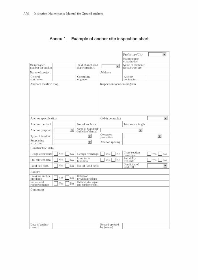
Inspection Maintenance Manual for Ground anchors110
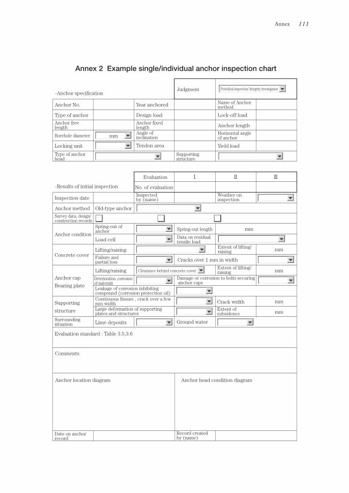
Annex 111
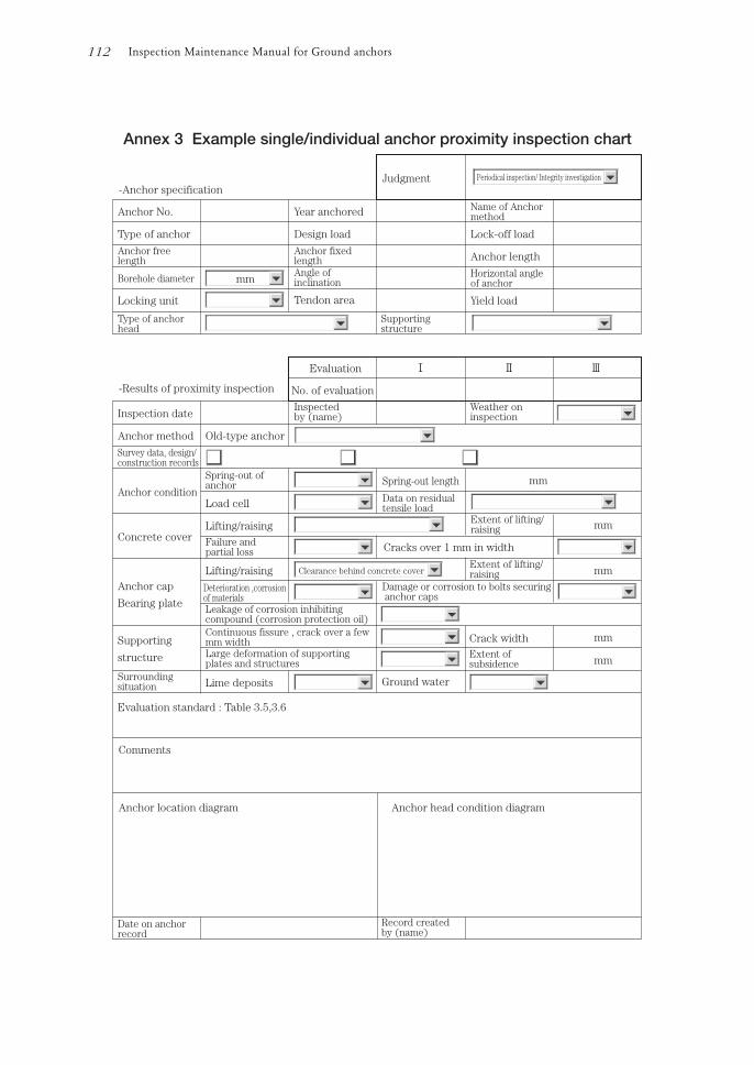
Inspection Maintenance Manual for Ground anchors112
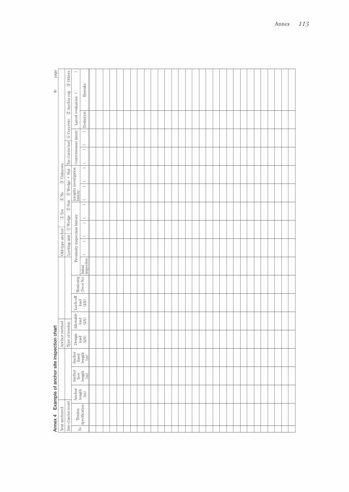
Annex 113

References 1.Japanese Society of Soil Mechanics & Foundation Engineering:
Earth anchors design/ construction standard (JSF Standard D1-77)
2.Japan Road Association:
Road Earthwork-Slope Stabilization Work Guideline-
3.Japanese Society of Soil Mechanics & Foundation Engineering: Ground anchor design/ construction standard (JSF Standard D1-88) 4.Japanese Society of Soil Mechanics & Foundation Engineering: Ground anchor design/ construction standard and its commentary
(Commentary for D1-88) 5.Japan Anchor Association: Ground anchor design/ construction instruction manual
(Instruction manual for D1-88) 6.Japanese Society of Soil Mechanics & Foundation Engineering: Revision of “Ground anchor design/construction standard (JGS4101-2000) 7.Japan Road Association: Road Earthwork-Slope Stabilization Work Guideline-2ndversion 8.The Japanese Geotechnical Society: Ground anchor design/ construction standard and commentary
(Commentary of JGS4101) 9.British Standards Institution (BSi):
Execution of Special geotechnical work-Ground anchors (BSEN 1537: 2000)
10.G.S.Littlejohn:
Permanent Ground Anchorages Review of Maintenance Testing, Service Monitoring and Associated
Field Practice (2005)
11.Post-Tensioning Institute(pti): Recommendations for Prestressed Rock and Soil Anchors (1996) 12.Post-Tensioning Institute(pti):
Recommendations for Prestressed Rock and Soil Anchors (2004)
13.Fédération Internationale de la Précontrainte(FIP): Corrosion and Corrosion protection for Prestressed Ground Anchorages (1986) 14.Fédération Internationale de la Précontrainte(FIP) Design and construction of prestressed ground anchorages (1996)
References 115
Inspection and Maintenance M
anual for Ground A
nchors
Inspection andMaintenance Manual forGround Anchors
Inspection andMaintenance Manual forGround Anchors
Pu
blic
Wo
rks R
ese
arc
h In
stitute
JAP
AN
AN
CH
OR
AS
SO
CIA
TIO
N
Public Works Research Institute
JAPAN ANCHOR ASSOCIATION
Contents
1 General1.1 Purpose of manual1.2 Scope1.3 Terms and definitions1.4 Related standards
2 Basic concept of anchor maintenance2.1 Current situation and theme of anchors2.2 Anchor deformation-causes and effects2.3 Inspection and Maintenance of anchors2.4 Keeping of records
3 Inspection of anchors3.1 Inspection flow3.2 Initial inspection3.3 Daily inspection3.4 Periodic inspection3.5 Emergency inspection3.6 Inspection records3.7 Judging the need for an integrity investigation
4 Integrity investigation of anchors4.1 Basic concept and flow of integrity investigation4.2 Integrity investigation planning4.3 Types of integrity investigation4.3.1 Preliminary survey4.3.2 Detailed investigation of the anchor heads4.3.3 Lift-off test4.3.4 Investigation below the anchor head4.3.5 Performance confirmation test4.3.6 Test of corrosion inhibiting compound (Test of CIC)4.3.7 Monitoring of residual tensile load4.3.8 Ultrasonic flaw test
5 Countermeasures for anchors5.1 Basic concept of countermeasures5.1.1 Normal anchors and anchors that need countermeasures5.1.2 Selection of countermeasures for anchors5.1.3 Anchor countermeasures5.1.4 Life extension countermeasure for normal anchors5.2 Countermeasures5.2.1 Maintenance and enhancement of corrosion protection5.2.2 Re-stressing and releasing of tensile load5.2.3 Renewal5.3 Emergency countermeasures5.4 Temporary countermeasures
6 Closing remarks
Annex1 Example of anchor site inspection chart2 Example single/individual anchor inspection chart3 Example single/individual anchor proximity inspection chart4 Example of anchor site inspection chart
References