advancements in ground anchors: carbon fibre … · advancements in ground anchors: ... failure of...
TRANSCRIPT
Advancements in Ground Anchors: Carbon Fibre Reinforced Polymer (CFRP) Strands
Matthew Sentry , Department of Civil Engineering, Monash University, Australia Abdelmalek Bouazza , Department of Civil Engineering, Monash University, Australia Riadh Al-Mahaidi , Department of Civil Engineering, Monash University, Australia Darren Loidl , Geotech Pty Ltd., Australia Chris Bluff , Geotech Pty Ltd., Australia Len Carrigan , Geotech Pty Ltd., Australia
ABSTRACT Steel tendon ground anchors are an integral construction technique for numerous civil engineering applications ranging from deep excavation support to resistance of structural uplift and overturning of superstructures. Corrosion and human error generally causes failure of steel tendon ground anchors. Several methods of minimising anchor system corrosion have been adopted over time to minimise ingress of corrosive substances. Anchors are still failing due to corrosion. Advancement in the development of corrosion resistant materials has been at the forefront of materials research. Research and development of FRP materials has enabled the progress of providing the industry with a more potentially robust anchor system aimed at eliminating current limitations encountered with steel strand ground anchors. This paper investigates current developments in FRP materials for ground anchor applications as an alternative to conventional steel tendon ground anchors.
Introduction Technological advancements of fibre reinforced polymer (FRP) products for applications in civil construction has allowed new products such as glass fibre (GFRP), aramid fibre (AFRP) and carbon fibre (CFRP) to pave the way for research into further improvements to the currently favoured steel tendon ground anchor system. This paper investigates current developments in FRP materials for ground anchor applications as an alternative to conventional steel tendons.
Corrosion limitations to steel tendon ground anchor s Corrosion in steel tendon ground anchors occurs as a consequence of in-homogeneities or impurities in the steel tendon or grout, or by the existence of salts, sulphates and other dissolved solids present in grout mixtures, soils or groundwater (Littlejohn and Bruce, 1977). International standards including EN1537:2000, AS5100.1-2004, BS8081:1989 require some type of corrosion protection for permanent ground anchor applications. Permanent steel tendon ground anchors require several areas to be corrosion protected, including tendon bond length, tendon free length, transition between anchor head and free length and the anchorage head. This paper will focus primarily on permanent ground anchor systems. Littlejohn (1987) reported on 35 known cases of corrosion related failures to steel tendon ground anchors, concluding that free length corrosion comprised 60% of failures, 34% of failures occurred in at the anchorage head and only 6% of failures occurred in the fixed
Sentry, Bouazza, Al-Mahaidi, Loidl, Bluff, Carrigan, Page 2
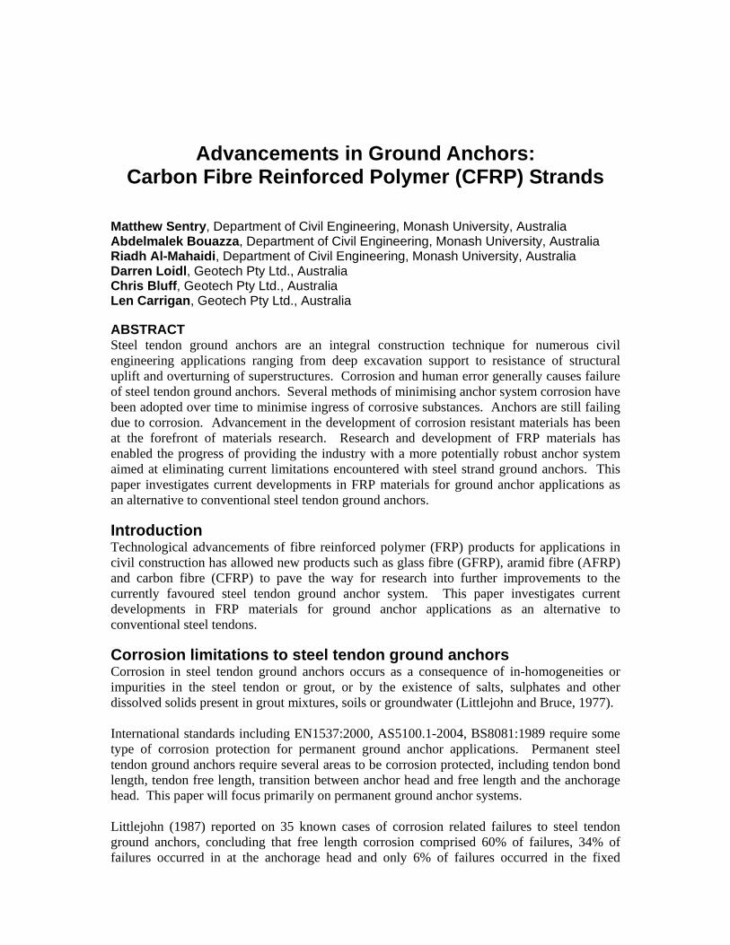
anchor length. Catastrophic structural failures can occur as a direct result of ground anchor failure due to corrosion (Figure 1). Littlejohn emphasised that the small percentage of failures within the fixed anchor length was a result of inadequate grout placement. Steel tendon corrosion occurs locally where the tendon intersects a crack in the surrounding grout, or as a result of damage to the corrosion protective sheaths (Weerasinghe and Adams, 1997). Grout cracks occur as a result of either shrinkage strains during curing or tensile loading of the anchor. Due to grout micro cracking, majority of standards do not permit grout to be considered as one of the two means for corrosion protection. Weerasinghe and Anson (1997) and Mothersille (2006) provided project examples where corrosion occurred above and below the anchor head, resulting in anchor strength reduction (Figure 1).
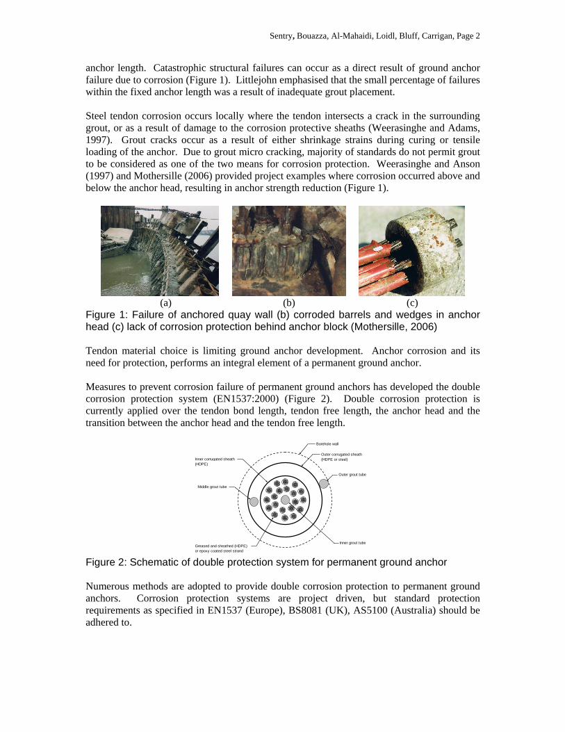
(a) (b) (c) Figure 1: Failure of anchored quay wall (b) corroded barrels and wedges in anchor head (c) lack of corrosion protection behind anchor block (Mothersille, 2006) Tendon material choice is limiting ground anchor development. Anchor corrosion and its need for protection, performs an integral element of a permanent ground anchor. Measures to prevent corrosion failure of permanent ground anchors has developed the double corrosion protection system (EN1537:2000) (Figure 2). Double corrosion protection is currently applied over the tendon bond length, tendon free length, the anchor head and the transition between the anchor head and the tendon free length.
Outer corrugated sheath (HDPE or steel)
Borehole wall
Outer grout tube
Inner corrugated sheath (HDPE)
Middle grout tube
Inner grout tubeGreased and sheathed (HDPE) or epoxy coated steel strand
Figure 2: Schematic of double protection system for permanent ground anchor Numerous methods are adopted to provide double corrosion protection to permanent ground anchors. Corrosion protection systems are project driven, but standard protection requirements as specified in EN1537 (Europe), BS8081 (UK), AS5100 (Australia) should be adhered to.
Sentry, Bouazza, Al-Mahaidi, Loidl, Bluff, Carrigan, Page 3
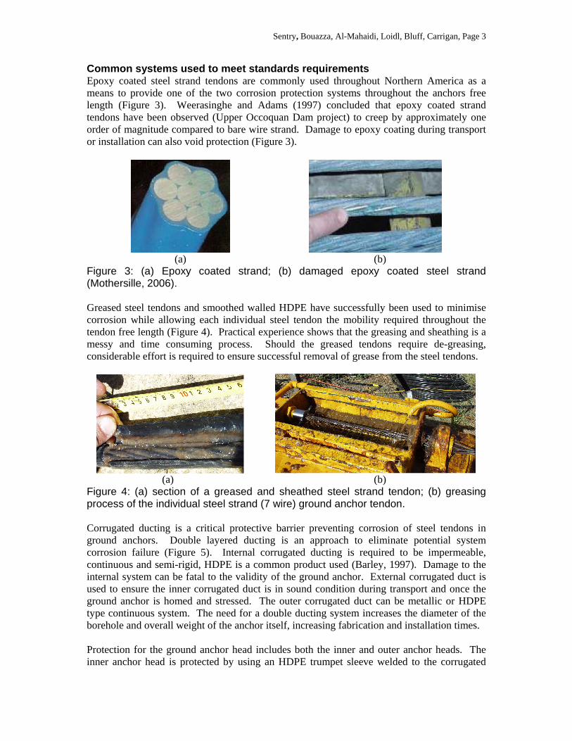
Common systems used to meet standards requirements Epoxy coated steel strand tendons are commonly used throughout Northern America as a means to provide one of the two corrosion protection systems throughout the anchors free length (Figure 3). Weerasinghe and Adams (1997) concluded that epoxy coated strand tendons have been observed (Upper Occoquan Dam project) to creep by approximately one order of magnitude compared to bare wire strand. Damage to epoxy coating during transport or installation can also void protection (Figure 3).
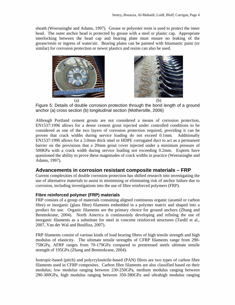
(a) (b) Figure 3: (a) Epoxy coated strand; (b) damaged epoxy coated steel strand (Mothersille, 2006). Greased steel tendons and smoothed walled HDPE have successfully been used to minimise corrosion while allowing each individual steel tendon the mobility required throughout the tendon free length (Figure 4). Practical experience shows that the greasing and sheathing is a messy and time consuming process. Should the greased tendons require de-greasing, considerable effort is required to ensure successful removal of grease from the steel tendons.
(a) (b) Figure 4: (a) section of a greased and sheathed steel strand tendon; (b) greasing process of the individual steel strand (7 wire) ground anchor tendon. Corrugated ducting is a critical protective barrier preventing corrosion of steel tendons in ground anchors. Double layered ducting is an approach to eliminate potential system corrosion failure (Figure 5). Internal corrugated ducting is required to be impermeable, continuous and semi-rigid, HDPE is a common product used (Barley, 1997). Damage to the internal system can be fatal to the validity of the ground anchor. External corrugated duct is used to ensure the inner corrugated duct is in sound condition during transport and once the ground anchor is homed and stressed. The outer corrugated duct can be metallic or HDPE type continuous system. The need for a double ducting system increases the diameter of the borehole and overall weight of the anchor itself, increasing fabrication and installation times. Protection for the ground anchor head includes both the inner and outer anchor heads. The inner anchor head is protected by using an HDPE trumpet sleeve welded to the corrugated
Sentry, Bouazza, Al-Mahaidi, Loidl, Bluff, Carrigan, Page 4
sheath (Weerasinghe and Adams, 1997). Grease or polyester resin is used to protect the inner head. The outer anchor head is protected by grease with a steel or plastic cap. Appropriate interlocking between the head cap and bearing plate must ensure no leaking of the grease/resin or ingress of water/air. Bearing plates can be painted with bitumastic paint (or similar) for corrosion protection or newer plastics and resins can also be used.
(a) (b) Figure 5: Details of double corrosion protection through the bond length of a ground anchor (a) cross section (b) longitudinal section (Mothersille, 2006) Although Portland cement grouts are not considered a means of corrosion protection, EN1537:1996 allows for a dense cement grout injected under controlled conditions to be considered as one of the two layers of corrosion protection required, providing it can be proven that crack widths during service loading do not exceed 0.1mm. Additionally EN1537:1996 allows for a 3.0mm thick steel or HDPE corrugated duct to act as a permanent barrier on the provisions that a 20mm grout cover injected under a minimum pressure of 500KPa with a crack width during service loading not exceeding 0.2mm. Experts have questioned the ability to prove these magnitudes of crack widths in practice (Weerasinghe and Adams, 1997).
Advancements in corrosion resistant composite mater ials – FRP Current complexities of double corrosion protection has shifted research into investigating the use of alternative materials to assist in minimising or eliminating risk of anchor failure due to corrosion, including investigations into the use of fibre reinforced polymers (FRP).
Fibre reinforced polymer (FRP) materials FRP consists of a group of materials containing aligned continuous organic (aramid or carbon fibre) or inorganic (glass fibre) filaments embedded in a polymer matrix and shaped into a product for use. Organic filaments are the primary choice for ground anchors (Zhang and Benmokrane, 2004). North America is continuously developing and refining the use of inorganic filaments as a substitute for steel in concrete reinforced structures (Tardif et al., 2007, Van der Wal and Boulfiza, 2007). FRP filaments consist of various kinds of load bearing fibres of high tensile strength and high modulus of elasticity. The ultimate tensile strengths of CFRP filaments range from 290-758GPa, AFRP ranges from 70-179GPa compared to prestressed steels ultimate tensile strength of 195GPa (Zhang and Benmokrane, 2004). Isotropic-based (pitch) and polycrylonitrile-based (PAN) fibres are two types of carbon fibre filaments used in CFRP composites. Carbon fibre filaments are also classified based on their modulus; low modulus ranging between 230-250GPa, medium modulus ranging between 290-300GPa, high modulus ranging between 350-380GPa and ultrahigh modulus ranging
Sentry, Bouazza, Al-Mahaidi, Loidl, Bluff, Carrigan, Page 5
between 480-760GPa. Low modulus carbon fibre filaments have a lower density, higher tensile and compressive strengths, higher tensile strain to failure than high modulus carbon fibre filament products and are considered less expensive than other carbon fibres. PAN based carbon fibres compared to Pitch based carbon fibres have a higher ultimate strain, but a lower modulus of elasticity. PAN based carbon fibres are more expensive than Pitch based carbon fibres. The main advantages of carbon fibres over other FRP products are high strength to weight ratio, high modulus to weight ratio, high fatigue strength, low coefficient of thermal expansion, and excellent moisture and chemical resistance (Mallick, 1993). Europe, Asia and North America manufacture aramid fibre filament products. Kevlar (modulus 82-179GPa), Twaron (modulus 70-130GPa) and Technora fibres (modulus 74GPa) are used depending on manufacture (Mallick, 1993). Aramid fibres benefits include excellent impact resistance, high strength, high stiffness and thermal stability. The achilles heel of aramid fibre filaments is that fibre strength decreases as water is absorbed into the fibres (Zhang and Benmokrane, 2005). Additionally, aramid fibres are sensitive to ultraviolet light and care must be taken during storage and transportation. For all FRP materials, a polymetric matrix is used to bond the fibres, protect the fibres against environmental effects and assist in the equalization of fibre forces and load transfers in the transverse direction. Thermoplastic and thermoset polymers can be applied with FRP fibre filaments to form an FRP composite material. Thermoplastic polymers including PVC, polyethylene and polypropylene are viscous polymers capable of being modified under temperature and more environmentally friendly than other products, but are difficult to combine with continuous fibres in a production operation (Zhang and Benmokrane, 2005). Thermoset polymers are classified as low viscous, low molecular-weight liquid with thermal stability and chemical resistivity and are said to exhibit reduced creep and stress relaxation when compared to thermoplastic polymers. Thermoset polymers including epoxy, polyester and vinyl ester are preferred resins for FRP material in civil engineering applications (Zhang and Benmokrane, 2005).
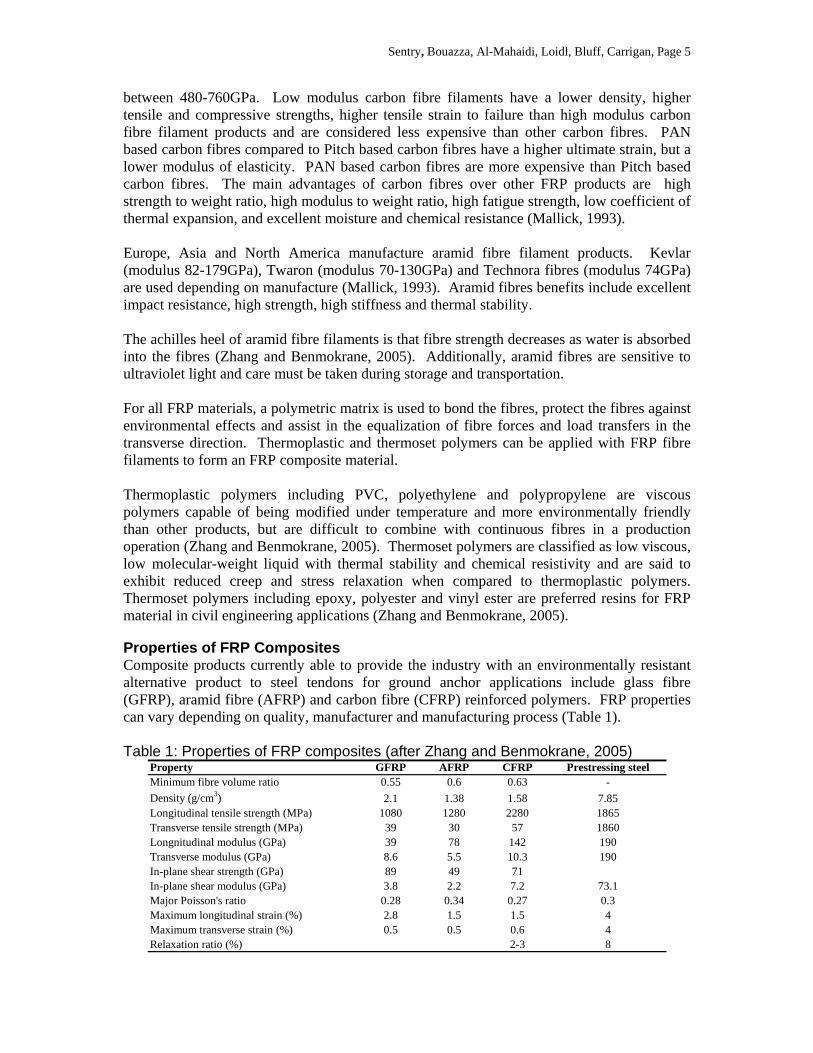
Properties of FRP Composites Composite products currently able to provide the industry with an environmentally resistant alternative product to steel tendons for ground anchor applications include glass fibre (GFRP), aramid fibre (AFRP) and carbon fibre (CFRP) reinforced polymers. FRP properties can vary depending on quality, manufacturer and manufacturing process (Table 1). Table 1: Properties of FRP composites (after Zhang and Benmokrane, 2005)
Property GFRP AFRP CFRP Prestressing steelMinimum fibre volume ratio 0.55 0.6 0.63 -
Density (g/cm3) 2.1 1.38 1.58 7.85Longitudinal tensile strength (MPa) 1080 1280 2280 1865Transverse tensile strength (MPa) 39 30 57 1860Longnitudinal modulus (GPa) 39 78 142 190Transverse modulus (GPa) 8.6 5.5 10.3 190In-plane shear strength (GPa) 89 49 71In-plane shear modulus (GPa) 3.8 2.2 7.2 73.1Major Poisson's ratio 0.28 0.34 0.27 0.3Maximum longitudinal strain (%) 2.8 1.5 1.5 4Maximum transverse strain (%) 0.5 0.5 0.6 4Relaxation ratio (%) 2-3 8
Sentry, Bouazza, Al-Mahaidi, Loidl, Bluff, Carrigan, Page 6
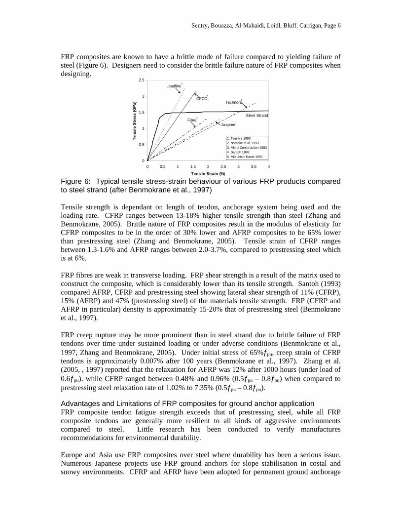
FRP composites are known to have a brittle mode of failure compared to yielding failure of steel (Figure 6). Designers need to consider the brittle failure nature of FRP composites when designing.
Leadline
CFCC
Fibra
Technora
Arapree
Steel Strand
0
0.5
1
1.5
2
2.5
0 0.5 1 1.5 2 2.5 3 3.5 4
Tensile Strain (%)
Ten
sile
Stre
ss (
GP
a)1. Taerw e 19932. Noritake et al. 19933. Mitsui Construction 19934. Santoh 19935. Mitsubishi Kasei 1992
1
4
5
3
2
Figure 6: Typical tensile stress-strain behaviour of various FRP products compared to steel strand (after Benmokrane et al., 1997) Tensile strength is dependant on length of tendon, anchorage system being used and the loading rate. CFRP ranges between 13-18% higher tensile strength than steel (Zhang and Benmokrane, 2005). Brittle nature of FRP composites result in the modulus of elasticity for CFRP composites to be in the order of 30% lower and AFRP composites to be 65% lower than prestressing steel (Zhang and Benmokrane, 2005). Tensile strain of CFRP ranges between 1.3-1.6% and AFRP ranges between 2.0-3.7%, compared to prestressing steel which is at 6%. FRP fibres are weak in transverse loading. FRP shear strength is a result of the matrix used to construct the composite, which is considerably lower than its tensile strength. Santoh (1993) compared AFRP, CFRP and prestressing steel showing lateral shear strength of 11% (CFRP), 15% (AFRP) and 47% (prestressing steel) of the materials tensile strength. FRP (CFRP and AFRP in particular) density is approximately 15-20% that of prestressing steel (Benmokrane et al., 1997). FRP creep rupture may be more prominent than in steel strand due to brittle failure of FRP tendons over time under sustained loading or under adverse conditions (Benmokrane et al., 1997, Zhang and Benmokrane, 2005). Under initial stress of 65%ƒpu, creep strain of CFRP tendons is approximately 0.007% after 100 years (Benmokrane et al., 1997). Zhang et al. (2005, , 1997) reported that the relaxation for AFRP was 12% after 1000 hours (under load of 0.6ƒpu), while CFRP ranged between 0.48% and 0.96% (0.5ƒpu – 0.8ƒpu) when compared to prestressing steel relaxation rate of 1.02% to 7.35% (0.5ƒpu – 0.8ƒpu).
Advantages and Limitations of FRP composites for ground anchor application FRP composite tendon fatigue strength exceeds that of prestressing steel, while all FRP composite tendons are generally more resilient to all kinds of aggressive environments compared to steel. Little research has been conducted to verify manufactures recommendations for environmental durability. Europe and Asia use FRP composites over steel where durability has been a serious issue. Numerous Japanese projects use FRP ground anchors for slope stabilisation in costal and snowy environments. CFRP and AFRP have been adopted for permanent ground anchorage
Sentry, Bouazza, Al-Mahaidi, Loidl, Bluff, Carrigan, Page 7
use while GFRP has been limited to temporary soil nails and anchors. The advantages and of CFRP include high tensile strength and modulus of elasticity, excellent fatigue and corrosion resistance, low thermal expansion, low stress relaxation and excellent moisture resistance. CFRP is the most expensive FRP tendon on market. The advantages to AFRP include excellent relaxation and corrosion resistance, high fatigue strength, moderate cost. AFRP limitations are its lowest strength and modulus of elasticity of all FRP tendons, strength loss whilst moist and at temperatures in excess of 150oC. GFRP is the cheapest FRP on the market; however, their limitations include lowest tensile strength, most sensitive to stress fatigue damage and creep rupture, most vulnerable to alkaline environment, may lose strength when exposed to moisture and increased temperature. All FRP materials are brittle in nature. FRP composite ground anchorage design FRP tendon ground anchors must consider the same design criterion and procedures as with conventional steel tendon ground anchors. Several quality standards are available to assist designing with FRP tendons. In addition to standards, government organisations have established rigorous guidelines complementing local and international standards. Adjustments to current standards and guidelines are required when replacing steel tendons with FRP tendons. Current documentation relevant to ground anchorage construction and for application of FRP tendons in ground anchors include (but not limited to) are EN 1537:2002–Execution of special geotechnical works–Ground Anchors; BS 8081:1989–Ground Anchorages; ACI 440.4R-04-Prestressing Concrete Structures with FRP Tendons; CAN/CSA S806–Design and Construction of Building Components with Reinforced Polymers; ISIS Canada-Educational Modules No. 1– 8; Post Tensioning Institute (USA)-Recommendations for Prestressed Rock and Soil Anchors and RTA QA Specification B114 Ed 2/Rev 3 1999
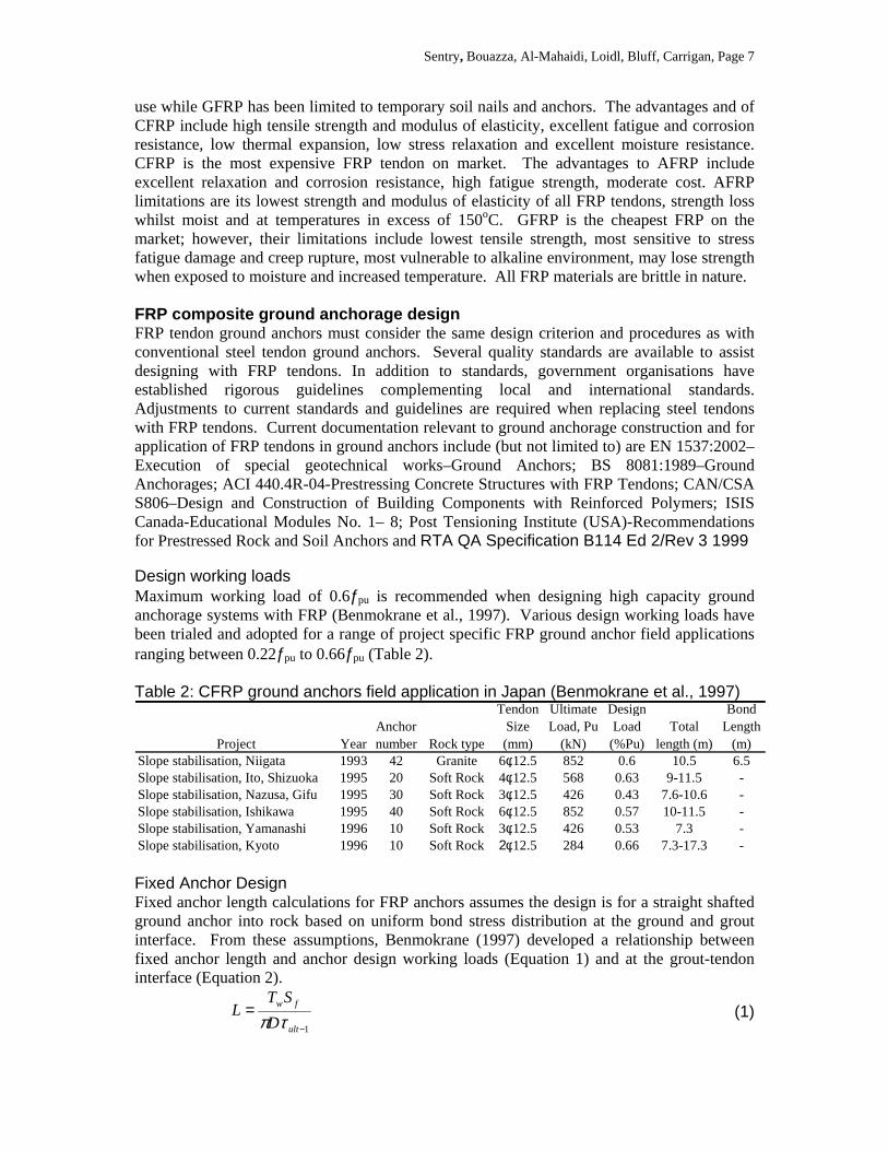
Design working loads Maximum working load of 0.6ƒpu is recommended when designing high capacity ground anchorage systems with FRP (Benmokrane et al., 1997). Various design working loads have been trialed and adopted for a range of project specific FRP ground anchor field applications ranging between 0.22ƒpu to 0.66ƒpu (Table 2). Table 2: CFRP ground anchors field application in Japan (Benmokrane et al., 1997)
Project YearAnchor number Rock type
Tendon Size (mm)
Ultimate Load, Pu
(kN)
Design Load (%Pu)
Total length (m)
Bond Length
(m)Slope stabilisation, Niigata 1993 42 Granite 6φ12.5 852 0.6 10.5 6.5Slope stabilisation, Ito, Shizuoka 1995 20 Soft Rock 4φ12.5 568 0.63 9-11.5 -Slope stabilisation, Nazusa, Gifu 1995 30 Soft Rock 3φ12.5 426 0.43 7.6-10.6 -Slope stabilisation, Ishikawa 1995 40 Soft Rock 6φ12.5 852 0.57 10-11.5 -Slope stabilisation, Yamanashi 1996 10 Soft Rock 3φ12.5 426 0.53 7.3 -Slope stabilisation, Kyoto 1996 10 Soft Rock2φ12.5 284 0.66 7.3-17.3 -
Fixed Anchor Design Fixed anchor length calculations for FRP anchors assumes the design is for a straight shafted ground anchor into rock based on uniform bond stress distribution at the ground and grout interface. From these assumptions, Benmokrane (1997) developed a relationship between fixed anchor length and anchor design working loads (Equation 1) and at the grout-tendon interface (Equation 2).
1−
=ult
fw
D
STL
τπ (1)
Sentry, Bouazza, Al-Mahaidi, Loidl, Bluff, Carrigan, Page 8
2−
=ult
fw
dn
STL
τπ (2)
Where: L=fixed anchor length, Tw=working load, and τult-x=ult shear strength, D,d=diameter. Bond values at the interface for grout and ground used for FRP tendons are coherent with what is currently being established for conventional prestressed steel tendon ground anchors (Littlejohn and Bruce, 1977). The wide variety of surface textures available in FRP tendons still requires considerable amounts of research to establish various bond values between tendon and grout for all usable FRP tendons (Zhang and Benmokrane, 2002). Some results published by Benmokrane et al. (1997) show the relationship of bond values between FRP tendons and cement grout under field conditions (Table 3) on selective FRP materials.
Table 3: Working bond values back-calculated from field applications of FRP ground anchors (after Benmokrane et al., 1997)
Tendon Type Tendon
Design load (kN)
Bond length (mm)
Working bond strength (MPa)
CFCC 6φ12.5 490.0 7.5 0.286φ12.5 510.0 6.5 0.33
Technora 9φ7.4 400.0 6.5 0.449φ7.4 400.0 3.0 0.96
FRP Anchorage Systems Tensile forces for FRP anchorage systems are transferred to the FRP anchor head system by anchorage in the same manner as steel tendon anchor systems. This load transfer requires lateral pressure and shear stresses to act on the FRP tendon surface in conjunction with high axial stresses applied to the anchor (Benmokrane et al., 1997). Sensitivity to lateral stresses and any notch or defect can limit its performance during stressing. Standard steel tendon based wedge type anchorage systems are currently inefficient and cause premature failure of the FRP tendon at the wedge interface. To accommodate for the transverse material property limitations of FRP at the anchor block research into different methods for anchorage has taken place over the past ten years (Zhang and Benmokrane, 2004, Campbell et al., 2000). There are no single method of anchorage to suit a wide variety of FRP materials and their unique profiles, but several anchorage methods have been developed including soft metal wedge and soft metal swage anchorage system, plug-in-cone anchorage system, bond-type anchorage system and soft cone anchorage system (Campbell et al., 2000, Reda and Shrive, 2003, Tardif et al., 2007). Soft metal wedge anchorage system is dependant on the gripping action of the wedges and/or teeth around the tendon perimeter accompanied by compression exerted by the wedges onto the FRP tendon (Reda and Shrive, 2003). There is great potential for this system as it is easy to assemble and use on site, but localised FRP tendons rupture at the wedge/tendon interface by excessive shear stress has restricted the potential (Tardif et al., 2007). Trials using a soft swage system, such as aluminium or copper minimises the excessive shear stress between the wedge and tendon have showed promise (Reda and Shrive, 2003, Tardif et al., 2007)(Figure 7(a)). Non metallic wedges are currently being researched as an alternative to soft metal wedges (Sireg, 2007) (Figure 7(c)).
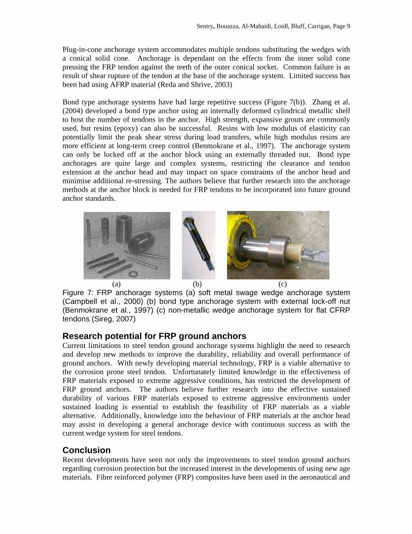
Sentry, Bouazza, Al-Mahaidi, Loidl, Bluff, Carrigan, Page 9
Plug-in-cone anchorage system accommodates multiple tendons substituting the wedges with a conical solid cone. Anchorage is dependant on the effects from the inner solid cone pressing the FRP tendon against the teeth of the outer conical socket. Common failure is as result of shear rupture of the tendon at the base of the anchorage system. Limited success has been had using AFRP material (Reda and Shrive, 2003) Bond type anchorage systems have had large repetitive success (Figure 7(b)). Zhang et al. (2004) developed a bond type anchor using an internally deformed cylindrical metallic shell to host the number of tendons in the anchor. High strength, expansive grouts are commonly used, but resins (epoxy) can also be successful. Resins with low modulus of elasticity can potentially limit the peak shear stress during load transfers, while high modulus resins are more efficient at long-term creep control (Benmokrane et al., 1997). The anchorage system can only be locked off at the anchor block using an externally threaded nut. Bond type anchorages are quite large and complex systems, restricting the clearance and tendon extension at the anchor head and may impact on space constraints of the anchor head and minimise additional re-stressing. The authors believe that further research into the anchorage methods at the anchor block is needed for FRP tendons to be incorporated into future ground anchor standards.
(a) (b) (c) Figure 7: FRP anchorage systems (a) soft metal swage wedge anchorage system (Campbell et al., 2000) (b) bond type anchorage system with external lock-off nut (Benmokrane et al., 1997) (c) non-metallic wedge anchorage system for flat CFRP tendons (Sireg, 2007)
Research potential for FRP ground anchors Current limitations to steel tendon ground anchorage systems highlight the need to research and develop new methods to improve the durability, reliability and overall performance of ground anchors. With newly developing material technology, FRP is a viable alternative to the corrosion prone steel tendon. Unfortunately limited knowledge in the effectiveness of FRP materials exposed to extreme aggressive conditions, has restricted the development of FRP ground anchors. The authors believe further research into the effective sustained durability of various FRP materials exposed to extreme aggressive environments under sustained loading is essential to establish the feasibility of FRP materials as a viable alternative. Additionally, knowledge into the behaviour of FRP materials at the anchor head may assist in developing a general anchorage device with continuous success as with the current wedge system for steel tendons.
Conclusion Recent developments have seen not only the improvements to steel tendon ground anchors regarding corrosion protection but the increased interest in the developments of using new age materials. Fibre reinforced polymer (FRP) composites have been used in the aeronautical and
Sentry, Bouazza, Al-Mahaidi, Loidl, Bluff, Carrigan, Page 10
motor industry for decades, it is only now that these advanced composite materials are becoming available for research into use for civil construction. FRP composites have the potential to minimise or eliminate current corrosion problems faced by designers and construction companies fabricating and installing steel tendon ground anchors. Research is still required prior to adopting FRP tendons as an alternative to steel strand into standards. Over the next few years the development of FRP composites will see more and more standards incorporate the new advanced composite materials for common project use.
Acknowledgements The authors would like to acknowledge Monash University, project sponsor Geotech Pty Ltd and Devon Mothersille.(ACI, 2005)
REFERENCES ACI (2005) ACI 440.3R-04 Guide Test Methods for Reinforcing or Strengthening Concrete Structures. American Concrete Institution (ACI). BARLEY, A. D. (1997) Ground Anchor Tendon Protected Against Corrosion and Damage by a Double Plastic Layer. ICE Conference on Ground Anchorages and Anchored Structures. London. BENMOKRANE, B., XU, H. & NISHIZAKI, I. (1997) Aramid and carbon fibre-reinforced plastic prestressed ground anchors and their field applications. Canadian Journal of Civil Engineering, 24, 968. CAMPBELL, T. I., SHRIVE, N. G., SOUDKI, K., AL-MAYAH, A., KEATLEY, J. P. & REDA, M. M. (2000) Design and evaluation of wedge-type anchor for fibre reinforced polymer tendons. Canadian journal of civil engineering, 27, 985. LITTLEJOHN, G. S. (1987) Ground Anchorages: corrosion performance. Proceedings - Institute of Civil Engineers, Part 1, 645-662. LITTLEJOHN, G. S. & BRUCE, D. A. (1977) Rock Anchors - State of the Art, Essex, England, Foundation Publications Ltd. MALLICK, D. K. (1993) Fibre-reinforced composites: materials, manufacturing, and design, New York, Marcel Deckker, Inc. MOTHERSILLE, D. (2006) ANCOLD Conference Presentation - Recent Development in Permanent Ground Anchor Technology. Geoserve Global Ltd & Geotech Pty Ltd. REDA, M. M. & SHRIVE, N. G. (2003) New Concrete Anchors for Carbon Fibre-reinforced Polymer Post-Tensioning tendons - Part 1: State-of-the-Art Review/Design. Aci Structural Journal. TARDIF, D., NEALE, K. W., DEMERS, M., ZAKI, A. R. & TADROS, G. (2007) Potential use of CFRP and GFRP in precast prestressed reinforced bridge deck system with extended service life. Durability and field applications of fibre reinforced polymer (FRP) compoisites for construction. Canada. VAN DER WAL, J. S. & BOULFIZA, M. (2007) A step forward in characterizing thhe performance of GFRP rods in concrete. Durability and field applications of fibre reinforeced polymer (FRP) composites for construction. Canada. WEERASINGHE, D. R. B. & ADAMS, M. D. (1997) A Technical Review of Rock Anchorage Practice 1976-1996. Ground Anchorages and Anchored Structures. London, Thomas Telford. WEERASINGHE, D. R. B. & ANSON, R. W. W. (1997) Investigation of long term performance and future behaviour of existing ground anchorages. International Conference on Ground Anchorages and Anchored Structures. London, Thomas Telford publications. ZHANG, B. & BENMOKRANE, B. (2002) Pullout Bond Properties of Fiber-Reinforced Polymer Tendons to Grout. Journal of Materials in Civil Engineering, 14, 399-408. ZHANG, B. & BENMOKRANE, B. (2004) Design and evaluation of a new bond-type anchorage system for fibre reinforced polymer tendons. Canadian Journal of Civil Engineering, 31, 14-26. ZHANG, B. & BENMOKRANE, B. (2005) Large model test of prestressed carbon fibre reinforced polymer ground anchors. Canadian Journal of Civil Engineering, 32, 1064.