input/output data definition document · 3 documents ... processing step 1: resampling of the input...
TRANSCRIPT

1
Input/Output Data Definition Document (IODD v1)
Version 1.0 21 December 2012
Prepared by
TU Wien, VUA, GeoVille, ETH Zürich, AWST, FMI, UCC and NILU

Input/Output Data Definition Document
Version 1.0 Date 21 December 2012
i
This document forms deliverable D2.8 and was compiled for the ESA Climate Change Initiative Phase 1 Soil Moisture Project (ESRIN Contract No: 4000106302 (4000104814/11/I-NB). For more information on the CCI programme of the European Space Agency (ESA) see http://www.esa-cci.org/.
Number of pages: 24
Authors: R. Kidd, D. Chung, W. Dorigo, R. De Jeu
Circulation (internal): Project consortium and science partners
External: ESA
Issue Date Details Editor
0.1 10-10-12 Document created R. Kidd
0.2 29-11-12 Structure Revision, and delivered as Draft to ESA for review
R. Kidd
0.3 12-12-12 Inclusion of overview diagram and revision of structure
R.Kidd, D. Chung
0.4 12-12-12 For input of data structure tables and figures D. Chung
1.0 21-12-12 Integration and revision for delivery R. Kidd
For any clarifications please contact Richard Kidd ([email protected]).

Input/Output Data Definition Document
Version 1.0 Date 21 December 2012
ii
Table of Content
LIST OF FIGURES ...................................................................................................................................................... IV LIST OF TABLES ....................................................................................................................................................... IV DEFINITIONS, ACRONYMS AND ABBREVIATIONS .............................................................................................................. V PROCESSING LEVELS ................................................................................................................................................. VI
1 EXECUTIVE SUMMARY ............................................................................................................................ 1
2 INTRODUCTION ....................................................................................................................................... 1
2.1 PURPOSE OF THE DOCUMENT ........................................................................................................................... 1 2.2 TARGETED AUDIENCE ...................................................................................................................................... 2
3 DOCUMENTS ........................................................................................................................................... 2
3.1 APPLICABLE DOCUMENTS ................................................................................................................................ 2 3.2 REFERENCE DOCUMENTS ................................................................................................................................. 2 3.3 BIBLIOGRAPHY .............................................................................................................................................. 3
4 OVERVIEW OF THE ECV PRODUCTION SYSTEM ....................................................................................... 4
5 I/O FOR ACTIVE RETRIEVAL ..................................................................................................................... 5
5.1 LEVEL 1 INPUT PRODUCTS ................................................................................................................................ 5 5.2 AUXILIARY PRODUCTS ..................................................................................................................................... 5 5.3 LEVEL 2 OUTPUT PRODUCTS ............................................................................................................................. 5
6 I/O FOR PASSIVE RETRIEVAL ................................................................................................................... 6
6.1 LEVEL 1 INPUT PRODUCTS ................................................................................................................................ 6 6.2 AUXILIARY PRODUCTS ..................................................................................................................................... 6 6.3 LEVEL 2 OUTPUT PRODUCTS ............................................................................................................................. 6
7 I/O FOR MERGING ALGORITHM .............................................................................................................. 7
7.1 INPUT DATA .................................................................................................................................................. 8 7.1.1 AMI-WS ........................................................................................................................................... 8 7.1.2 ASCAT .............................................................................................................................................. 8 7.1.3 SMMR ............................................................................................................................................ 8 7.1.4 SSM/I .............................................................................................................................................. 9 7.1.5 TMI .................................................................................................................................................. 9 7.1.6 AMSR-E ......................................................................................................................................... 9 7.1.7 GLDAS NOAH Average Layer 1 (0 – 10cm) Soil Moisture .................................................. 10 7.1.8 GLDAS Soil Porosity .................................................................................................................. 10

Input/Output Data Definition Document
Version 1.0 Date 21 December 2012
iii
7.1.9 Correlation Coefficient ............................................................................................................... 10 7.1.10 Vegetation Optical Depth ...................................................................................................... 10
7.2 RESAMPLING ............................................................................................................................................... 11 7.2.1 Temporal Resampling .................................................................................................................... 11 7.2.2 Spatial Resampling ........................................................................................................................ 11 7.2.3 Data structure after resampling .................................................................................................... 12
7.3 RESCALING ................................................................................................................................................. 12 7.4 ACTIVE MERGING AND PASSIVE MERGING ........................................................................................................ 13 7.5 RESCALING TO GLDAS CLIMATOLOGY .............................................................................................................. 14 7.6 COMBINING ACTIVE AND PASSIVE MERGED DATA .............................................................................................. 15
8 VALIDATION DATASETS ......................................................................................................................... 16
8.1 ISMN ....................................................................................................................................................... 16 8.2 GLDAS ..................................................................................................................................................... 16
9 CONCLUDING COMMENTS .................................................................................................................... 16
10 BIBLIOGRAPHY ...................................................................................................................................... 16

Input/Output Data Definition Document
Version 1.0 Date 21 December 2012
iv
List of Figures
Figure 7-1: An overview of processes in the ECV SSM product generation .............................. 7
Figure 7-2: Processing step 1: Resampling of the input data sets ........................................... 11
Figure 7-3: Processing step 2: Rescaling .................................................................................. 12
Figure 7-4 Processing step 3: Active Merging and Passive Merging ........................................ 13
Figure 7-5: Processing step 4: Rescaling to GLDAS climatology ............................................... 14
Figure 7-6 Processing step 5: Combining Active and Passive Merged data ............................. 15
Figure 7-7 Spatial and temporal coverage of soil moisture products from different sensors in the final product. ...................................................................................................................... 16
List of Tables
Table 10-1 Processing Level Codes for Remotely Sensed Data Sets ......................................... vi
Table 7-1: Level 2 Active AMI WS data ...................................................................................... 8
Table 7-2: Level 2 Active ASCAT data ......................................................................................... 8
Table 7-3 Level 2 Passive SSMR data.......................................................................................... 9
Table 7-4 Level 2 Passive SSM/I data ......................................................................................... 9
Table 7-5 Level 2 Passive TMI data ............................................................................................ 9
Table 7-6 Level 2 Passive AMSR-E data .................................................................................... 10
Table 7-7 Ancillary Data GLDAS NOAH Average Layer Soil Moisture ...................................... 10
Table 7-8 Ancillary Data GLDAS Soil Porosity ........................................................................... 10
Table 7-9 Ancillary Data Correlation Coefficient ...................................................................... 10
Table 7-10 Ancillary Data Vegetation Optical Depth (VOD) ..................................................... 11
Table 7-11 Data Structure after resampling............................................................................. 12
Table 7-12 Data Structure provided to the final product ........................................................ 16

Input/Output Data Definition Document
Version 1.0 Date 21 December 2012
v
Definitions, acronyms and abbreviations
AMI-WS Active Microwave Instrument - Windscat (ERS-1 & 2)
AMSR-E Advanced Microwave Scanning Radiometer-Earth Observing System
ANO Anomaly
AQUA NASA Earth Science satellite mission (formerly EOS-PM)
ASCAT Advanced Scatterometer (Metop)
ATBD Algorithm Theoretical Basis Document
CDF Cumulative Distribution Function
DARD Data Access and Retrieval Document
DGG Discrete Global Grid
DPM Detailed Processing Model
ECV Essential Climate Variable
ERS European Remote Sensing Satellite (ESA)
ERS European Remote Sensing Satellite (ESA)
ESA European Space Agency
ESD Estimated Standard Deviation
GLDAS-Noah Globa Land Data Assimilation System- Noah model
IODD Input Output Data Definition Document
LPRM Land Parameter Retrieval Model
LUT Look Up Table
METOP Meteorological Operational Satellite (EUMETSAT)
NASA National Aeronautics and Space Administration
ORI Original (Time Series)
PSD Product Specification Document
SM Soil Moisture
SMMR Scanning Multichannel Microwave Radiometer
TMI TRMM Microwave Imager
TRMM Tropical Rainfall Measuring Mission
UTC Coordinated Universal Time
VOD Vegetation Optical Depth
WARP soil Water Retrieval Package

Input/Output Data Definition Document
Version 1.0 Date 21 December 2012
vi
Processing Levels1
Level <ProcessingLevel>Code
Description Based on Source
Level 0 L0 Unprocessed instrument and payload data at full resolution. GHRSST
Level 1A L1A Reconstructed unprocessed instrument data at full resolution, time referenced, and annotated with ancillary information, including radiometric and geometric calibration coefficients and georeferencing parameters, computed and appended, but not applied, to L0 data.
GHRSST
Level 1B L1B Level 1A data that have been processed to sensor units.
GHRSST
Level 1C L1C Level 1B data that have been further processed, eg by correcting radiances or by mapping onto A spatial grid, prior to deriving geophysical variables from the data.
SMOS data products definition
Level 2 L2 Retrieved environmental variables at the same resolution and location as the level 1 source.
CEOS handbook2
Level 2Pre-processed
L2P Geophysical variables derived from Level 1 source data at the same resolution andlocation as the level 1 data, typically in a satellite projection with geographic information.These data form the fundamental basis for higher-level CCI products.
GHRSST
Level 3 L3 Level 2 variables mapped on a defined grid with reduced requirements for ancillary data. Three types of L3 products are defined:
GHRSST
L3U Uncollated (L3U): L2 data granules remapped to a space grid without combining any observations from overlapping orbits.
L3C Collated (L3C):Observations combined from a single instrument into a space-time grid.
L3S Super-collated (L3S): observations combined from multiple instruments into a space-time grid.
Level 4 L4 Data sets created from the analysis of lower level data that result in gridded, gap-freeproducts.
GHRSST
Table 10-1 Processing Level Codes for Remotely Sensed Data Sets
1 Extracted from [RD-4] 2 http://wiki.ieee-earth.org/@api/deki/files/7/=Handbook_0802.pdf
Input/Output Data Definition Document
Version 1.0 Date 21 December 2012
1
1 Executive Summary
[This chapter will provide the executive summary for the document... ]
2 Introduction
The Input/Output Data Definition Document (IODD) aims to provide a complete list and a detailed technical description of all data products used for and generated by the prototype processing system.
It describes the format, structure and data ranges of all
• required satellite input data,
• auxiliary files
• generated output products
• test and validation data sets
The IODD version 1 release focuses on the data flows from the ingestion of level 2 active and passive data into the ECV processing system to the generation of the level 3 ECV soil moisture product. An overview of the data flows that are covered is provided in Figure 7-1, and can be seen comprise of data flows between the following processes; resampling, rescaling, active merging and passive merging, rescaling to GLDAS climatology, and combing active and passive merged data. The IODD covers both the data flowing into and out from the processes.
The document is structured as envisaged for the release of version 2 of the IODD, which is due at end of 2013. Version 2 will revise and update version 1 and is planned also to include the data flows relevant to level 1 to level 2 productions for both active and passive systems and validation data sets.
2.1 Purpose of the document
The purpose of this Input/Output Data Definition Document is to provide an overview of the data structures and formats of the data flows within the ECV prototype production system. The document is provided to enable system engineers to understand and implement the production system as outlined in the Detailed Processing Model (DPM), as provided [RD-4].
The document does not duplicate information already provided in the Data Access Requirement Document (DARD) deliverable (D1.3) or in the product specification documents (PSD) deliverable D1.2, which provides the complete specification of the ECV SM output product.

Input/Output Data Definition Document
Version 1.0 Date 21 December 2012
2
2.2 Targeted audience
This document targets mainly
• IT experts and system design engineers working within the CCI SM project • IT experts and system design engineers working to install ECV production system
3 Documents
3.1 Applicable documents
The documents outlined here detail the scope and focus for the work that is reported in this document.
[AD-1] Phase 1 of the ESA Climate Change Initiative Soil- Moisture- cci. ESRIN Contract No: 4000104814/11/I-NB
[AD-2] ESA Climate Change Initiative Phase 1, Statement of Work for Soil Moisture and Ice Sheets, European Space Agency, EOEP-STRI-EOPS-SW-11-0001.
[AD-3] Technical Proposal (Part 3) in response to ESA Climate Change Initiative Phase 1 ESRIN/AO/1-6782/11/I-NB, Vienna University of Technology.
3.2 Reference documents
The section provides a list of references documents upon which this document is either based, or is required to be referenced by the reader in order to obtain the full information intended by the authors.
[RD-1] Algorithm Theoretical Baseline Document (ATDB) Version 0, Climate Change Initiative Phase 1 Soil Moisture Project, 30th April 2012, http://www.esa-soilmoisture-cci.org/node/119
[RD-2] Data Access Requirements Document (DARD), Version 1.2, Climate Change Initiative Phase 1 Soil Moisture Project, 13th April 2012, http://www.esa-soilmoisture-cci.org/node/119
[RD-3] Product Specification Document (PSD), version, 0.3, Climate Change Initiative Phase 1 Soil Moisture Project, 18th June 2012, http://www.esa-soilmoisture-cci.org/node/119
[RD-4] Detailed Processing Model (DPM), Version 1.0, Climate Change Initiative Phase 1 Soil Moisture Project, 28th September 2012, http://www.esa-soilmoisture-cci.org/node/119

Input/Output Data Definition Document
Version 1.0 Date 21 December 2012
3
3.3 Bibliography
A complete bibliographic list, detailing scientific text or publications that support arguments or statements made within the current document is provided in section 10.

Input/Output Data Definition Document
Version 1.0 Date 21 December 2012
4
4 Overview of the ECV production system3
The Soil Moisture ECV production system starts from level 1 calibrated backscatter values and level 1 calibrated brightness temperatures for scatterometers and radiometers, respectively. The ECV production system requires a modular system design where new or updated level 2 datasets can be easily ingested, quality controlled, and assimilated in the ECV production. In Phase I of the project, only input level 2 products based on the TU Wien method (for scatterometers) and the VUA-NASA LPRM algorithm (for radiometers) are considered. This results in the following structure of the ECV production system:
A. Level 2 soil moisture retrieval for individual scatterometer data sets using the TU Wien method as first (Wagner et al., 1999).
B. Level 2 soil moisture retrieval for single radiometer data sets using the VUA-NASA method (Owe et al., 2008).
C. Fusion of the active Level 2 data sets into a homogenized active surface soil moisture ECV.
D. Fusion of the passive Level 2 data into a homogenized passive surface soil moisture ECV.
E. Fusion of the merged active and passive data sets from steps 2 and 3 into homogenized active+passive surface soil moisture ECV.
This release (version 1) of the IODD document provides a description of the data flows between the processes involved in the production system from the level 2 data input data to the generation of the level 3 ECV product and therefore only addresses points C,D and E. An overview of the processes included in this document is provided in Figure 7-1.
3 Adapted from [RD-4]

Input/Output Data Definition Document
Version 1.0 Date 21 December 2012
5
5 I/O for active retrieval
[Intentionally left blank: This section will be included in IODD version 2]
5.1 Level 1 input products
5.2 Auxiliary products
5.3 Level 2 output products

Input/Output Data Definition Document
Version 1.0 Date 21 December 2012
6
6 I/O for passive retrieval
[Intentionally left blank: This section will be included in IODD version 2]
6.1 Level 1 input products
6.2 Auxiliary products
6.3 Level 2 output products

Input/Output Data Definition Document
Version 1.0 Date 21 December 2012
7
7 I/O for merging algorithm
Level 2 derived soil moisture products from active and passive space borne systems form the main inputs to the merging algorithm of the ECV prototype production system and are supported by a limited set of ancillary data as shown in Figure 7-1.
A detailed view of the data flows within the 5 main processing steps in the merging process, namely resampling, rescaling, active merging and passive merging, rescaling to GLDAS climatology, and combing active and passive merged data are provided in the following subsections.
Figure 7-1: An overview of processes in the ECV SSM product generation

Input/Output Data Definition Document
Version 1.0 Date 21 December 2012
8
7.1 Input data
The following tables show all required level 2 soil moisture input data including four ancillary data sets.
7.1.1 AMI-WS
Variable Type Offset Scale Min physical value
Max physical value
Unit Missing Value
JD double precision float 0 1 2448473.5 05-AUG-1991
2454252.499 31-MAY-2007
day -999999.
SM float 0 1 0 100 % -999999.
SM_NOISE float 0 1 0 100 % -999999.
FLAG byte 0 1 0 255 – 255
Table 7-1: Level 2 Active AMI WS data
7.1.2 ASCAT
Variable Type Offset Scale Min physical value
Max physical value
Unit Missing Value
JD double precision float 0 1 2448473.5 05-AUG-1991
2454252.499 31-MAY-2007
day -999999.
SM float 0 1 0 100 % -999999.
SM_NOISE float 0 1 0 100 % -999999.
FLAG byte 0 1 0 255 – 255
DIR String 0 – ‘A’ ‘D’ – 255
PDB byte 0 1 0 255 – 255
SSF byte 0 1 0 255 – 255
Table 7-2: Level 2 Active ASCAT data
7.1.3 SMMR
Variable Type Offset Scale Min physical value
Max physical value
Unit Missing Value
JD Double precision Float 0 1 2443810.193 28-OCT-1978
2447022.193 14-AUG-1987
day -1
SMC Byte 0 1 0 100 % 255.
OPTC Byte 0 1 0 100 % 255
FLAG Byte 0 1 0 255 – 255

Input/Output Data Definition Document
Version 1.0 Date 21 December 2012
9
MODE Byte 0 1 65 (‘A’) 68 (‘D’) – 255
RFI Byte 0 1 0 255 – 255
LST Integer 0 1 0 255 – -9999
Table 7-3 Level 2 Passive SSMR data
7.1.4 SSM/I
Variable Type Offset Scale Min physical value
Max physical value
Unit Missing Value
DT Double precision Float 0 1 2446984.5 08-JUL-1987
2454647.5 30-JUN-2008
day -1
VALUE Byte 0 1 0 100 % 255.
Table 7-4 Level 2 Passive SSM/I data
7.1.5 TMI
Variable Type Offset Scale Min physical value
Max physical value
Unit Missing Value
DT Double precision Float 0 1 2446984.5 08-JUL-1987
2454647.5 30-JUN-2008
day -1
VALUE Byte 0 1 0 100 % 255.
Table 7-5 Level 2 Passive TMI data
7.1.6 AMSR-E
Variable Type Offset Scale Min physical value
Max physical value
Unit Missing Value
JD double precision float 0 1 2452444.5 19-JUN-2002
2455838.499 03-OCT-2011
day -1
SMC Integer 0 1.0 0 100 % -32678
SMX Integer 0 1.0 0 100 % -32678
SMC_ERROR Integer 0 0.01 0 100 % -32678
SMX_ERROR Integer 0 0.01 0 100 % -32678
OPTC Integer 0 0.01 0 - – -32678
OPTX Integer 0 0.01 0 - – -32678
MASK Integer 0 1 0 - – -32678
RFI Integer 0 1 - - – -32678
MODE Byte 0 1 65 (‘A’) 68 (‘D’) – 255

Input/Output Data Definition Document
Version 1.0 Date 21 December 2012
10
RES_C Integer 0 0.1 0 - Kelvin -32678
RES_X Integer 0 0.1 0 - Kelvin -32678
TS Integer 0 0.1 0 - Kelvin -32678
Table 7-6 Level 2 Passive AMSR-E data
7.1.7 GLDAS NOAH Average Layer 1 (0 – 10cm) Soil Moisture
Variable Type Offset Scale
Min physical
value
Max physical value
Unit Missing Value
DT Double precision Float 0 1 2451544.5 01-JAN-2000
2456200.5 30-SEP-2012
day -1
VALUE Byte 0 1 0 100 kgm-3 255.
Table 7-7 Ancillary Data GLDAS NOAH Average Layer Soil Moisture
7.1.8 GLDAS Soil Porosity
Variable Type Offset Scale
Min physical
value
Max physical value
Unit Missing Value
VALUE Float 0 1 0 100 % -99999.
Table 7-8 Ancillary Data GLDAS Soil Porosity
7.1.9 Correlation Coefficient
Variable Type Offset Scale
Min physical
value
Max physical value
Unit Missing Value
R Float 0 1 0 1 – -99999.
Table 7-9 Ancillary Data Correlation Coefficient
7.1.10 Vegetation Optical Depth
Variable Type Offset Scale
Min physical
value
Max physical value
Unit Missing Value
JD Double precision float 0 1 2447161.5 01-JAN-1988
2455838.5 03-OCT-2011
day -99999.
VOD Float 0 1 0 1 – NaN
SENSOR Byte 0 1 1 10 255

Input/Output Data Definition Document
Version 1.0 Date 21 December 2012
11
Table 7-10 Ancillary Data Vegetation Optical Depth (VOD)
7.2 Resampling
The input data sets AMI-WS, ASCAT, SMMR, AMSR-E, TMI, and SSM/I are fed in to the resampling process to transform them into a harmonized data format
Figure 7-2: Processing step 1: Resampling of the input data sets
7.2.1 Temporal Resampling
The temporal resolution of the merged product is one day. The reference time for the merged dataset set at 0:00 UTC. For each day, the observations within the reference time of 0:00 UTC ±12 hours are considered. If more than one observation falls within this period, the observation closest in time is selected. This strategy results in data gaps when no observations within ±12 hours from the reference time are available. For the modelled soil moisture datasets no resampling is required.
7.2.2 Spatial Resampling
Nearest neighbour resampling is performed to convert the various grid systems into the common 0.25 degree regular grid. For each grid point in the reference (regular grid) data set, this resampling technique receives the value of the closest grid point in the input dataset.

Input/Output Data Definition Document
Version 1.0 Date 21 December 2012
12
7.2.3 Data structure after resampling
Variable Type Offset Scale Min physical value
Max physical value
Unit Missing Value
JD Double precision float 0 1 2443813.5 01-NOV-1991
2455561.5 31-DEC-2010
day -999999.
SM Float 0 1 – – – -999999.
SM_NOISE Float 0 1 0 – – -999999.
FLAG Byte 0 1 0 255 – 255
SENSOR Byte 0 1 1 10’ – 255
Table 7-11 Data Structure after resampling
The values for julian date (JD) are set according to the resampling algorithm. Soil moisture and soil moisture noise values come untouched from its original data set. Flag values are not set in this processing step but in the merging step 3 and 5. Depending on the input data, the sensor variable will be assigned to values from 1 to 10, with respect to their input sensors SMMR (1), SSMI (2), TMI (3), AMSR-E (4), AMI-WS (5), ASCAT (6). Values from 7 to 10 will be used for the merged data (see merging processing step 3 and 5).
As shown in Figure 7-2 ASCAT and AMR-E data are used as reference for the rescaling process of the AMI-WS, TMI, SSM/I, and SMMR. The latter is rescaled against the merged climatology of SSM/I and TMI with AMSR-E (after their rescaling, see overview Figure 7-1). As reference data sets and after rescaling, ASCAT and AMSR-E are directly fed into the merging process.
7.3 Rescaling
Figure 7-3: Processing step 2: Rescaling
Before merging can take place the data sets need to be rescaled by CDF matching into a common climatology. Figure 7-3 shows that ASCAT is used as reference (climatology) to

Input/Output Data Definition Document
Version 1.0 Date 21 December 2012
13
rescale the AMI-WS on the active microwave soil moisture data, whereas AMSR-E is the reference data set for all rescaling procedure on the passive data side. Due to atmospheric influences on SSM/I – this issue is described in the ATBD section 8.3.1.1.2 – its rescaling needs the calculation seasonality and anomaly of the AMSR-E and SSM/I. The rescaling of SMMR needs the merged TMI, SSM/I and ASMR-E, which is produced in processing 3, as input reference data.
The rescaled soil moisture and soil moisture noise data (see section 7.2.3) are brought into a value range of their reference data. The data structure itself is left unchanged and is as reported in Table 7-11.
7.4 Active Merging and Passive Merging
Figure 7-4 Processing step 3: Active Merging and Passive Merging
The merging of the AMI-WS and ASCAT needs the rescaled AMI-WS data coming from processing step 2 and the rescaled ASCAT data from processing step 1.
The merging of the passive data sets shows some more dependencies as Figure 7-4 depicts. First the rescaled SSM/I and the rescaled TMI are merged with AMSR-E. The output of this merging flows into the rescaling process as well into the merging of SMMR.
This processing step 3 creates as output data the merged active and the merged passive data. Data structures for both data sets are described in section 7.2.3 reported in Table 7-11.

Input/Output Data Definition Document
Version 1.0 Date 21 December 2012
14
7.5 Rescaling to GLDAS climatology
Figure 7-5: Processing step 4: Rescaling to GLDAS climatology
The merged active and the merged passive data sets need to be rescaled by CDF matching to the GLDAS-NOAH climatology. For this rescaling process two ancillary data sets are needed as input:
a) the GLDAS NOAH is a reanalysis data set using the NOAH land surface model; layer 1 (0 – 10 cm)
b) GLDAS Soil Porosity
This processing step creates the merged active and the merged passive data sets in the GLDAS climatology. The soil moisture and the soil moisture noise value are then brought into a range between 0 and 80. The data structure is described in section 7.2.3 reported in Table 7-11.
Input/Output Data Definition Document
Version 1.0 Date 21 December 2012
15
7.6 Combining Active and Passive Merged Data
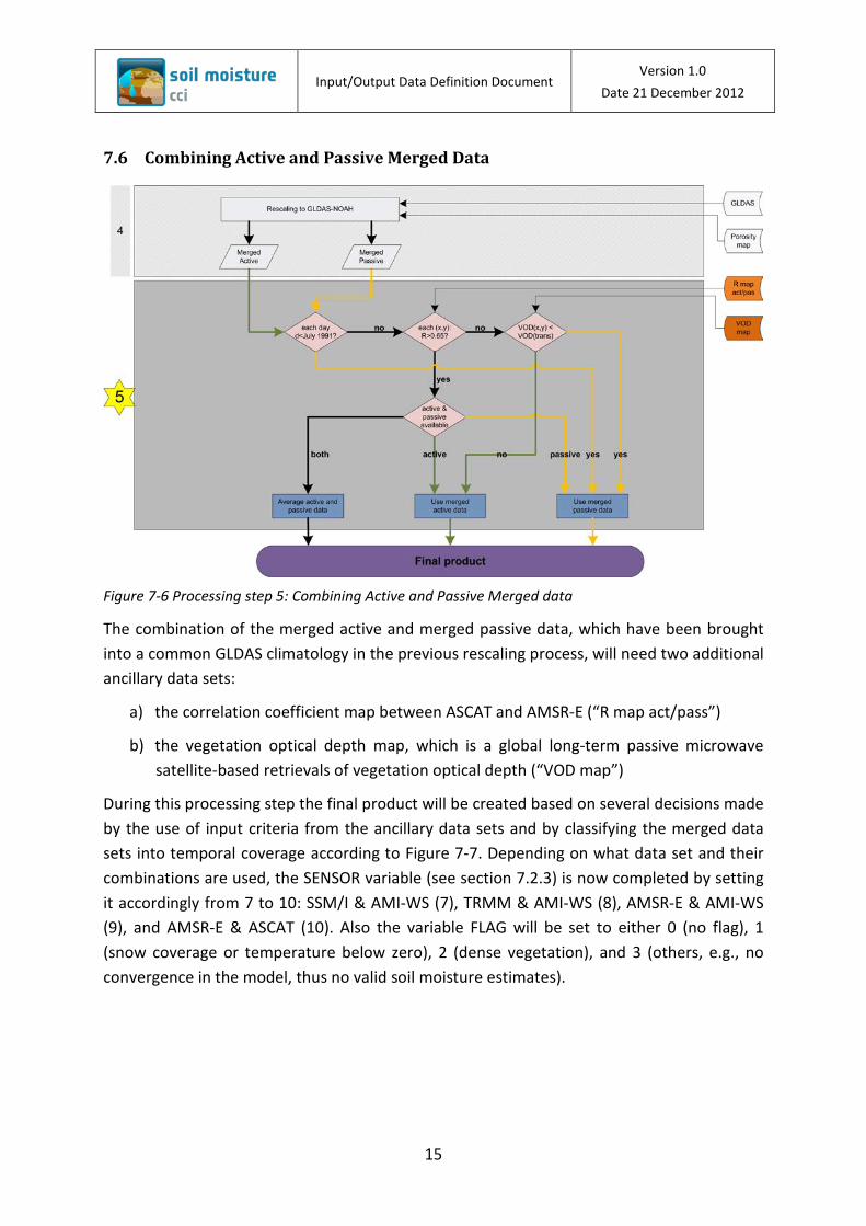
Figure 7-6 Processing step 5: Combining Active and Passive Merged data
The combination of the merged active and merged passive data, which have been brought into a common GLDAS climatology in the previous rescaling process, will need two additional ancillary data sets:
a) the correlation coefficient map between ASCAT and AMSR-E (“R map act/pass”)
b) the vegetation optical depth map, which is a global long-term passive microwave satellite-based retrievals of vegetation optical depth (“VOD map”)
During this processing step the final product will be created based on several decisions made by the use of input criteria from the ancillary data sets and by classifying the merged data sets into temporal coverage according to Figure 7-7. Depending on what data set and their combinations are used, the SENSOR variable (see section 7.2.3) is now completed by setting it accordingly from 7 to 10: SSM/I & AMI-WS (7), TRMM & AMI-WS (8), AMSR-E & AMI-WS (9), and AMSR-E & ASCAT (10). Also the variable FLAG will be set to either 0 (no flag), 1 (snow coverage or temperature below zero), 2 (dense vegetation), and 3 (others, e.g., no convergence in the model, thus no valid soil moisture estimates).

Input/Output Data Definition Document
Version 1.0 Date 21 December 2012
16
Figure 7-7 Spatial and temporal coverage of soil moisture products from different sensors in the final product.
The data structure output to the final product is as provided in Table 7-12
Variable Type Offset Scale Min physical value
Max physical value
Unit Missing Value
JD Double precision float 0 1 2443813.5 01-NOV-1991
2455561.5 31-DEC-2010
day -999999.
SM Float 0 1 – – – -999999.
SM_NOISE Float 0 1 0 – – -999999.
FLAG Byte 0 1 0 255 – 255
SENSOR Byte 0 1 1 10’ – 255
Table 7-12 Data Structure provided to the final product
8 Validation Datasets
[This section will be included in IODD version 2 after conclusion of Round Robin Activities.. ]
8.1 ISMN
8.2 GLDAS
9 Concluding Comments
[Intentionally left blank This section will be included in IODD version 2.. ]
10 Bibliography
Owe, M., de jeu, R. and Holmes, T., 2008: Multisensor historical climatology of satellite-derived global land surface moisture. Journal of Geophysical Research-Earth Surface 113 (F1), F01002.
Wagner, W., Lemoine, G. and Rott, H., 1999: A Method for Estimating Soil Moisture from ERS Scatterometer and Soil Data. Remote Sensing of Environment 70, 191-207.