innovated relays for railway signalling and interlocking
TRANSCRIPT
ISBN 978-80-261-0386-8, © University of West Bohemia, 2015
Innovated relays for railway signalling and interlocking
Ivan Konečný, Department of Applied Electronics and
Telecommunications University of West Bohemia
Pilsen, Czech Republic
Michael Kroupa, Radek Polanský, Pavel Prosr, František Steiner
Regional Innovation Centre for Electrical Engineering
University of West Bohemia Pilsen, Czech Republic
Abstract – This paper deals with accelerated life tests and a verification of technical parameters of an innovated electromechanical relay intended for applications in railway signalling and interlocking.
Keywords-Electromechanical relay; safety; insulation resistance; endurance; climatic testing
I. INTRODUCTION Technical devices ensuring a safe train ride, called
as signaling and interlocking equipment, must fulfill, besides the requirements on a high reliability in a fault-free state (a requirement for a so-called functional safety), normative requirements on a behavior at occurrence of eventual random failures (a requirement for so-called technical safety) as well. Generally, if there is a fault condition of some functional unit of the interlocking equipment, then a system must take a so-called safe state, when a train passage must be stopped or limited automatically to avoid an eventual accident.
An electromechanical relay with an armature drop out ensured by gravity and with a special design of a contact mechanism (so-called N type relay) is one of basic elements of railway interlocking devices with an inherent safety. By a structural design of the relay it is ensured, that all closing contacts of the relay are switched-off at a loss of a relay coil excitation. Although currently there are mostly used solid state interlocking systems with a technical safety ensured by a redundant architecture (so-called composed fail safety), N type relays still have got their irreplaceable position even at present, in interface circuits of solid state interlocking devices especially.
Within the formation of new European standards there is a new mandatory standard being prepared specifying technical properties of N type relays. Therefore a manufacturer of these relays in Czech Republic, DUO Opočno s.r.o., made an important construction innovation of these relays to fulfill all requirements in the sense of the prepared standard.
Due to an impartial comparison of the innovated N type relay with a former type of relay being produced up now, there were performed measurement and tests in the laboratories of KET FEL ZČU Plzeň. Their description and results are presented in following part of this paper.
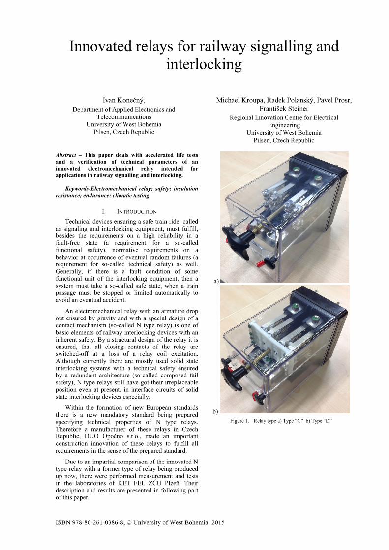
a)
b) Figure 1. Relay type a) Type “C” b) Type “D”
II. MEASUREMENT DESCRIPTION
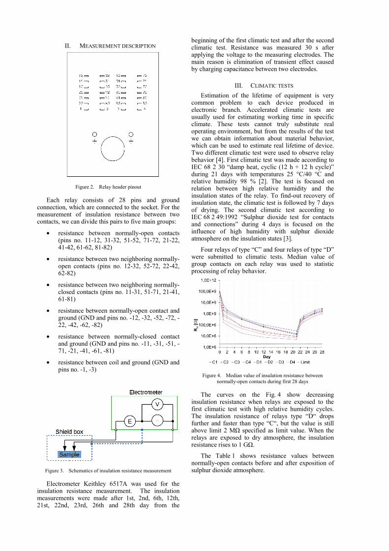
Figure 2. Relay header pinout
Each relay consists of 28 pins and ground connection, which are connected to the socket. For the measurement of insulation resistance between two contacts, we can divide this pairs to five main groups:
• resistance between normally-open contacts (pins no. 11-12, 31-32, 51-52, 71-72, 21-22, 41-42, 61-62, 81-82)
• resistance between two neighboring normally-open contacts (pins no. 12-32, 52-72, 22-42, 62-82)
• resistance between two neighboring normally-closed contacts (pins no. 11-31, 51-71, 21-41, 61-81)
• resistance between normally-open contact and ground (GND and pins no. -12, -32, -52, -72, -22, -42, -62, -82)
• resistance between normally-closed contact and ground (GND and pins no. -11, -31, -51, -71, -21, -41, -61, -81)
• resistance between coil and ground (GND and pins no. -1, -3)
Figure 3. Schematics of insulation resistance measurement
Electrometer Keithley 6517A was used for the insulation resistance measurement. The insulation measurements were made after 1st, 2nd, 6th, 12th, 21st, 22nd, 23rd, 26th and 28th day from the
beginning of the first climatic test and after the second climatic test. Resistance was measured 30 s after applying the voltage to the measuring electrodes. The main reason is elimination of transient effect caused by charging capacitance between two electrodes.
III. CLIMATIC TESTS Estimation of the lifetime of equipment is very
common problem to each device produced in electronic branch. Accelerated climatic tests are usually used for estimating working time in specific climate. These tests cannot truly substitute real operating environment, but from the results of the test we can obtain information about material behavior, which can be used to estimate real lifetime of device. Two different climatic test were used to observe relay behavior [4]. First climatic test was made according to IEC 68 2 30 “damp heat, cyclic (12 h + 12 h cycle)” during 21 days with temperatures 25 °C/40 °C and relative humidity 98 % [2]. The test is focused on relation between high relative humidity and the insulation states of the relay. To find-out recovery of insulation state, the climatic test is followed by 7 days of drying. The second climatic test according to IEC 68 2 49:1992 “Sulphur dioxide test for contacts and connections” during 4 days is focused on the influence of high humidity with sulphur dioxide atmosphere on the insulation states [3].
Four relays of type “C” and four relays of type “D” were submitted to climatic tests. Median value of group contacts on each relay was used to statistic processing of relay behavior.
Figure 4. Median value of insulation resistance between normally-open contacts during first 28 days
The curves on the Fig. 4 show decreasing insulation resistance when relays are exposed to the first climatic test with high relative humidity cycles. The insulation resistance of relays type “D“ drops further and faster than type “C“, but the value is still above limit 2 MΩ specified as limit value. When the relays are exposed to dry atmosphere, the insulation resistance rises to 1 GΩ.
The Table 1 shows resistance values between normally-open contacts before and after exposition of sulphur dioxide atmosphere.
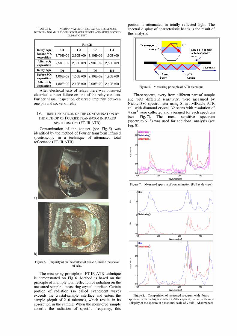
TABLE I. MEDIAN VALUE OF INSULATION RESISTANCE BETWEEN NORMALLY-OPEN CONTACTS BEFORE AND AFTER SECOND
CLIMATIC TEST
Relay type
RIZ (Ω)
C1 C2 C3 C4 Before SO2 exposition 1,70E+09 2,60E+09 3,10E+09 1,90E+09
After SO2
exposition 2,50E+09 2,60E+09 2,90E+09 2,50E+09
Relay type D1 D2 D3 D4 Before SO2 exposition 1,00E+09 1,50E+09 2,10E+09 1,90E+09
After SO2
exposition 1,80E+09 2,10E+09 2,00E+09 2,10E+09
After electrical tests of relays there was observed electrical contact failure on one of the relay contacts. Further visual inspection observed impurity between one pin and socket of relay.
IV. IDENTIFICATILON OF THE CONTAMINATION BY THE METHOD OF FOURIER TRANSFORM INFRARED
SPECTROSCOPY (FT-IR ATR) Contamination of the contact (see Fig. 5) was
identified by the method of Fourier transform infrared spectroscopy in a technique of attenuated total reflectance (FT-IR ATR).
a)
b)
Figure 5. Impurity a) on the contact of relay; b) inside the socket of relay
The measuring principle of FT-IR ATR technique is demonstrated on Fig. 6. Method is based on the principle of multiple total reflection of radiation on the measured sample - measuring crystal interface. Certain portion of radiation (so called evanescent wave) exceeds the crystal-sample interface and enters the sample (depth of 2~6 microns), which results in its absorption in the sample. When the monitored sample absorbs the radiation of specific frequency, this
portion is attenuated in totally reflected light. The spectral display of characteristic bands is the result of this analysis.
Figure 6. Measuring principle of ATR technique
Three spectra, every from different part of sample and with different sensitivity, were measured by Nicolet 380 spectrometer using Smart MIRacle ATR cell with diamond crystal. 32 scans with resolution of 4 cm-1 were collected and averaged for each spectrum (see Fig. 7). The most sensitive spectrum (spectrum N. 3) was used for additional analysis (see Fig. 8).
Contanimation_1Contanimation_2Contanimation_3
-0,00
0,05
0,10
0,15
0,20
Abso
rban
ce
1000 2000 3000 4000 Wavenumbers (cm-1)
Figure 7. Measured spectrta of contamination (Full scale view)
Urea
0,5
1,0
Abs
Contanimation_3
-0,0
0,1
0,2
Abs
1000 2000 3000 4000 Wavenumbers (cm-1)
UreaContanimation_3
-0,00
0,05
0,10
0,15
0,20
Abso
rban
ce
1000 2000 3000 4000 Wavenumbers (cm-1)
Figure 8. Comparision of measured spectrum with library spectrum with the highest match a) Stack specra, b) Full scaleview (display of the spectra in a maximal scale of y axis - Absorbance)
Based on the FT-IR analysis the contamination was identified as a urea. Generally, products based on urea and melamine are called aminoplastics. There are condensates of formaldehyde with compounds containing amine or amide groups.
An additional analysis of the cover contacts material was made from the reason of identification of the possible cause of the creation of the contaminated layer. Sample from the cover was prepared in form of powder to ensure good homogeneity and close contact of the measured material with the detection crystal. The measured spectrums together with library spectra with the best match are shown in Fig 9.
Cover 0,1
Abs
Paper (Cellulose)
0,1Abs
Phenol-formaldehyde resin
0,05
0,10
Abs
1000 2000 3000 Wavenumbers (cm-1)
CoverPaper (Cellulose)Phenol-formaldehyde resin
0,080
0,085
0,090
0,095
0,100
0,105
0,110
0,115
Abso
rban
ce
700 750 800 Wavenumbers (cm-1)
Figure 9. FT-IR spectra a) material of the cover, b) detailed view of spectral area corresponding to phenol-formaldehyd resin
Based on comparison with libraries the highest match of measured spectra is with cellulose paper which could be used in a cover material as a filler. As seen from Fig. 9 b, there are an additional spectral bands corresponding to phenol-formaldehyde resin (probably used as a binder of the cover material). The results of FT-IR measurement of contamination and cover material corresponds each other. As is known, the decomposition of aminoplastics (condensates of formaldehyde) is accompanied with formation of urea. [1] From this reason, the presence of urea on the contact could be caused by their releasing during manufacturing process of the material or eventually during thermal degradation.
V. RESULTS Climatic testing of relays type “C” and type “D” shows small difference when they are exposed to high humidity atmosphere during long time period. Innovated relay type “D” decreases value of insulation resistance more rapidly and reaches lower value, but each value is still above specified limit. For this reason, it is possible to say that innovated relays meet both the requirements of the European standards as well as requirements for insulation
resistance. Although conducted innovation decreased insulation resistance the specified limit was fulfilled. Contamination found on one of the relay terminals after exposure to the SO2 atmosphere does not affect the relay reliability, because is not related to the aging of functional parts of relay.
ACKNOWLEDGMENT This research has been supported by the European
Regional Development Fund and the Ministry of Education, Youth and Sports of the Czech Republic under the Regional Innovation Centre for Electrical Engineering (RICE), project No. CZ.1.05/2.1.00/03.0094.
REFERENCES [1] MLEZIVA, Josef. Polymery - výroba, struktura, vlastnosti a
použití. 1. vyd. Praha: Sobotáles, 1993, 525 s. ISBN 8090157041.
[2] ČSN EN 60068-2-30 ed. 2. Zkoušení vlivů prostředí - Část 2-30: Zkoušky - Zkouška Db: Vlhké teplo cyklické (cyklus 12 h + 12 h). Praha: Český normalizační institut, 1.8.2006.
[3] ČSN IEC 68-2-49. Elektrotechnické a elektronické výrobky. Základní zkoušky vlivu vnějších činitelů prostředí. Část 2-49: Návod ke zkoušce Kc: Zkouška oxidem siřičitým pro kontakty a spoje. Praha: Český normalizační institut, 1.4.1992.
[4] MIL-HDBK-338B. Electronic reliability design handbook. Philadelphia: Standardization Documents Order Desk, 1998. Dostupné z: http://www.sre.org/pubs/Mil-Hdbk-338B.pdf