information for global reach
TRANSCRIPT

AFRL-IF-RS-TR-2005-308 Final Technical Report August 2005 INFORMATION FOR GLOBAL REACH Northrop Grumman IT - TASC
APPROVED FOR PUBLIC RELEASE; DISTRIBUTION UNLIMITED.
AIR FORCE RESEARCH LABORATORY INFORMATION DIRECTORATE
ROME RESEARCH SITE ROME, NEW YORK

STINFO FINAL REPORT This report has been reviewed by the Air Force Research Laboratory,
Information Directorate, Public Affairs Office (IFOIPA) and is releasable to the National Technical Information Service (NTIS). At NTIS it will be releasable to the general public, including foreign nations.
AFRL-IF-RS-TR-2005-308 has been reviewed and is approved for
publication APPROVED: /s/
DANIEL HAGUE Project Engineer
FOR THE DIRECTOR: /s/
WARREN H. DEBANY, JR., Technical Advisor Information Grid Division Information Directorate

REPORT DOCUMENTATION PAGE Form Approved
OMB No. 074-0188 Public reporting burden for this collection of information is estimated to average 1 hour per response, including the time for reviewing instructions, searching existing data sources, gathering and maintaining the data needed, and completing and reviewing this collection of information. Send comments regarding this burden estimate or any other aspect of this collection of information, including suggestions for reducing this burden to Washington Headquarters Services, Directorate for Information Operations and Reports, 1215 Jefferson Davis Highway, Suite 1204, Arlington, VA 22202-4302, and to the Office of Management and Budget, Paperwork Reduction Project (0704-0188), Washington, DC 20503 1. AGENCY USE ONLY (Leave blank)
2. REPORT DATEAUGUST 2005
3. REPORT TYPE AND DATES COVERED Final Aug 98 – Dec 03
4. TITLE AND SUBTITLE INFORMATION FOR GLOBAL REACH
6. AUTHOR(S) Patricia J. Baskinger, Stuart Card, Mary C. Chruscicki, Mike Demase, Ron Smetek, and Steve Zabele
5. FUNDING NUMBERS C - F30602-98-C-0252 PE - 63789F PR - 4216 TA - 02 WU - 02
7. PERFORMING ORGANIZATION NAME(S) AND ADDRESS(ES) Northrop Grumman IT – TASC 55 Walkers Brook Drive Reading Massachusetts 01867
8. PERFORMING ORGANIZATION REPORT NUMBER
N/A
9. SPONSORING / MONITORING AGENCY NAME(S) AND ADDRESS(ES) Air Force Research Laboratory/IFGC 525 Brooks Road Rome New York 13441-4505
10. SPONSORING / MONITORING AGENCY REPORT NUMBER
AFRL-IF-RS-TR-2005-308
11. SUPPLEMENTARY NOTES AFRL Project Engineer: Dan Hague/IFGC/(315) 330-1885/ [email protected]
12a. DISTRIBUTION / AVAILABILITY STATEMENT APPROVED FOR PUBLIC RELEASE; DISTRIBUTION UNLIMITED.
12b. DISTRIBUTION CODE
13. ABSTRACT (Maximum 200 Words) Information for Global Reach (IFGR) system enables the exchange of secure, critical information among Air Force Decision makers, and combat forces. IFGR consists of selected Commercial off the shelf (COTS) and Government off the shelf (GOTS) software components, integrated to provide an extension of the Global Information Grid to mobile users.Through the integration of commercial and Department of Defense (DoD) wireless communication assets, IFGR provides a set of services much like an Internet Service provider to deployed and deploying forces. Using intelligence gained from the data flow and communications link characteristics, IFGR establishes, and seamlessly maintains, a virtual network among highly mobile and fixed nodes. IFGR's unique gateway engine obviates the users' need to know what communication device is sending or receiving their information, or what communications link(s) they are using. IFGR is standards-based, enabling users and their applications to "plug in" to IFGR and have a seamless connection to the Internet.
15. NUMBER OF PAGES85
14. SUBJECT TERMS Mobile Networking, Intelligent Information Management, Smart Bandwidth Management, Quality of Service, IP-enabled Global Communications, IP over Military Radios 16. PRICE CODE
17. SECURITY CLASSIFICATION OF REPORT
UNCLASSIFIED
18. SECURITY CLASSIFICATION OF THIS PAGE
UNCLASSIFIED
19. SECURITY CLASSIFICATION OF ABSTRACT
UNCLASSIFIED
20. LIMITATION OF ABSTRACT
ULNSN 7540-01-280-5500 Standard Form 298 (Rev. 2-89)
Prescribed by ANSI Std. Z39-18 298-102

i
Table of Contents EXECUTIVE SUMMARY ............................................................................................................ 1
1.0 INTRODUCTION .............................................................................................................. 3 1.1 Background and Program Status............................................................................. 3 1.2 Transition of IFGR Technologies ........................................................................... 5 1.3 Key IFGR Technologies ......................................................................................... 7 1.4 Overview of the Final Report ................................................................................. 7
2.0 INTELLIGENT INFORMATION MANAGER ................................................................ 8 2.1 Objectives for the IIM............................................................................................. 8 2.2 Technical Approach for the IIM ............................................................................. 8
2.2.1 Secure System Access Control ................................................................... 9 2.2.2 APPLICATION LAYER: Application and End-User Support ................ 10 2.2.3 Error Handling and Reporting .................................................................. 13 2.2.4 Assured, Secure Information Delivery ..................................................... 13 2.2.5 Intelligent Data/Message Processing ........................................................ 14 2.2.6 User/Mission/Link-Based Quality of Service (QoS) ................................ 15 2.2.7 Future Technology Enhancements............................................................ 18
3.0 TRANSPORT LAYER..................................................................................................... 21 3.1 Goals and Objectives for the Transport Layer of the IFGR System..................... 21 3.2 Technical Approach for the Transport Layer........................................................ 21 3.3 Transport Layer Enhancements ............................................................................ 22 3.4 Future Technologies and Capabilities proposed for the Transport Layer............. 23
4.0 NETWORK LAYER ........................................................................................................ 25 4.1 Goals and Objectives for the Network Layer of the IFGR System ...................... 25 4.2 Technical Approach for the Network Layer ......................................................... 25
4.2.1 Concurrent Multipath Routing (CMR): Simultaneous Use of All Assets 25 4.2.2 Explicit Channel Reservation (ECR): Prioritized Access to Comm Assets
................................................................................................................... 27 4.2.3 Mobile IP: Transparent, and Seamless Mobile Networking..................... 31 4.2.4 Secure Mobile Routing and QoS Support................................................. 38 4.2.5 Additional Efficiency Considerations....................................................... 39
4.3 IFGR Network Layer Enhancements.................................................................... 39 4.3.1 Unmanaged Traffic Support ..................................................................... 39 4.3.2 Additional QoS Management Enhancements to ECR .............................. 40 4.3.3 Robust Operation Support......................................................................... 40
4.4 Future Technology Enhancements Proposed for the Network Layer................... 41

ii
4.4.1 Streaming Media Support ......................................................................... 41 4.4.2 One Way Traffic Support.......................................................................... 43 4.4.3 Aircraft-to-Aircraft Routing...................................................................... 43 4.4.4 Network Evolution: IPv6 Support ............................................................ 44
5.0 GLOBAL COMMUNICATIONS AND MEDIA ACCESS CONTROL ........................ 45 5.1 Objectives for GC Subsystem and Media Access Control ................................... 45 5.2 Technical Approach for the GC Subsystem and Media Access Control .............. 46
5.2.1 Connection Management (CM) Sublayer ................................................. 46 5.2.2 Wireless Media Access Control (WMAC) Sublayer ................................ 48 5.2.3 Remote Control Interface (RCI) Subsystem............................................. 55 5.2.4 Link Monitor and Control Agent (LM&C) Subsystem ............................ 61
6.0 INFORMATION ASSURANCE...................................................................................... 67 6.1 Goals and Security Objectives for Information Assurance................................... 67 6.2 Technical Approach for the IFGR Information Assurance Architecture (IAA)... 68
6.2.1 IFGR Secure Mission Manager ................................................................ 69 6.2.2 IFGR Secure Messenger ........................................................................... 72
6.3 Enhancements to Current IFGR Messaging Functionality ................................... 73 6.3.1 Token Issuance.......................................................................................... 74 6.3.2 Authentication........................................................................................... 74 6.3.3 Access Control .......................................................................................... 74 6.3.4 Cryptographic Message Protection ........................................................... 74 6.3.5 Time Controlled Messaging...................................................................... 74 6.3.6 Biometric Identity Integration................................................................... 74 6.3.7 Message Processing of Different Clearance Levels.................................. 74 6.3.8 Cryptographic Revocation ........................................................................ 74 6.3.9 Message Integrity...................................................................................... 75 6.3.10 Image Integrity.......................................................................................... 75 6.3.11 Robustness ................................................................................................ 75 6.3.12 NSA Certification Process ........................................................................ 75 6.3.13 Continued Integration Of Information Assurance Components ............... 75
6.4 Future Technologies And Capabilities Proposed for Information Assurance ...... 75 6.4.1 IFGR Toolbox........................................................................................... 75 6.4.2 DITSCAP.................................................................................................. 78

iii
List of Figures
Figure E-1: IFGR System Architecture ...........................................................................................2
Figure 1-1: Joint STARS DRIER Experiment IFGR and Sample Screen Shot...............................6
Figure 2-1: Default User Interface.................................................................................................11
Figure 2-2: Local Administrator Interface.....................................................................................11
Figure 2-3: Global Administrator User Interface...........................................................................12
Figure 2-4: IFGR Knowledge Base Schema..................................................................................17
Figure 3-1: SCPS-TP Test bed.......................................................................................................22
Figure 3-2: IFGR Transport Layer Testing Procedure ..................................................................23
Figure 4-1: CMR allows simultaneous use of all available communication links ........................26
Figure 4-2: Example ECR Operation.............................................................................................29
Figure 4-3: Changing points of attachment makes a mobile user unreachable with traditional IP routing....................................................................................................................................32
Figure 4-4: Mobile IP (MIP) operations in Co-located mode........................................................34
Figure 4-5: Mobile IP operations using mobility support (Foreign Agent) addressing mode.......34
Figure 4-6: Prioritized delivery of unmanaged traffic within IFGR using a Weighted Fair Queuing approach. .................................................................................................................43
Figure 5-1: GC Subsystem Architecture........................................................................................46
Figure 5-2: CM State Transition Diagram.....................................................................................47
Figure 5-3: Utilization of D-TDMA vs TDMA: Simulation Results ...........................................50
Figure 5-4: Transfer Times for D-TDMA vs TDMA: Simulation Results...................................50
Figure 5-5: Analysis of Contention-Based Protocols ....................................................................51
Figure 5-6: Proposed Framing Structure........................................................................................52
Figure 5-7: WMAC Base Station State Transition ........................................................................53
Figure 5-8: WMAC Mobile Terminal State Transition .................................................................54
Figure 5-9: Base Station Header ....................................................................................................54
Figure 5-10: RCI Basic Functionality............................................................................................57
Figure 5-11: RCI GUI - RF5710A.................................................................................................59
Figure 5-12: RCI GUI - RF5022 (SSB Mode)...............................................................................60
Figure 5-13: RCI GUI – PRC117 (Standard Mode) ......................................................................60
Figure 5-14: LM&C State Transition Diagram (HF Link) ............................................................62

iv
Figure 5-15: LM&C UHF Handoff................................................................................................63
Figure 5-16: LM&C Manager Process ..........................................................................................64
Figure 5-17: LM&C Manager GUI................................................................................................64
Figure 5-18: LM&C Start Link GUI..............................................................................................65
Figure 5-19: LM&C Manager Process ..........................................................................................65
Figure 5-20: LM&C Monitor GUI.................................................................................................66
Figure 6-1: Information Assurance Concept of Operations...........................................................68
Figure 6-2: IFGR Mission Management Screen............................................................................70
Figure 6-3: IFGR New Mission Screen .........................................................................................71
Figure 6-4: IFGR User Management Screen .................................................................................71
Figure 6-5: Standard Logon ...........................................................................................................72
Figure 6-6: Tri-Mode Authentication Logon.................................................................................72
Figure 6-7: IFGR Secure Email Client Application ......................................................................73
Figure 6-8: Information Hiding Using Steganographic Methods ..................................................76
Figure 6-9: Standard Voice Communication .................................................................................77
Figure 6-10: Voice Communication with Embedded Alert ...........................................................77
List of Tables
Table 2-1: Mission/User Priority Parameters ................................................................................16
Table 2-2: Priority Parameters Values...........................................................................................16
Table 5-1: CM Primitives ..............................................................................................................48
Table 5-2: Generic Frame Format..................................................................................................54
Table 5-3: WMAC Primitives........................................................................................................56
Table 5-4: RCI Command Set........................................................................................................58

1
SUMMARY
The Air Force Research Laboratory has led the technology development of the Information for Global Reach (IFGR) system to enable the exchange of secure, critical information among Air Force decision makers, combat forces, and coalition partners. IFGR consists of selected commercial off the shelf (COTS) and Government off the shelf (GOTS) software components, integrated to provide an effective extension of the Global Information Grid to mobile users.
In 1995 Congress funded a study to assess the information and communications infrastructure required to support the extension of the Global Information Grid to the Mobile Operational Environment. Because of Air Mobility Command’s (AMC) operational requirements for Global C4I Information Exchange in a highly mobile, bandwidth disadvantaged operating environment, the Air Force selected AMC to drive the study. This led to an Air Force Research Laboratory (AFRL) Advanced Technology Demonstration (ATD) program.
The IFGR ATD included a number of significant event and milestones: • The IFGR ATD kicked off in the Joint Expeditionary Experiment 1999 (JEFX 99)
when Electronic Systems Command (ESC) recommended that IFGR and AMC experiment with the concept of using the future Global Air Traffic Management (GATM) equipment for command and control applications.
• During JEFX 2000, IFGR participated in five initiatives that effectively addressed the entire flow of battle, from mission initialization as the conflict unfolded, the transport of troops and equipment into the area of conflict, and the evacuation and care of the injured.
• AMC requested the IFGR program participate in a Secretary of Defense sponsored technology demonstration for the “New Economy Leaders”.
• IFGR participated in the Theater Medical Information Program, Pacific Warrior, a joint field exercise.
• During the fall of 2003, the IFGR Team participated in a simulated aeromedical evacuation (AE) field evaluation. IFGR’s participation was the result of a jointly sponsored AMC and the AFC2ISRC initiative that was approved as a Warfighter Rapid Acquisition Program (WRAP).
• At the completion of this contract phase of the program, preparations were being made to integrate IFGR onto the Joint STARS system.
IFGR is composed of three software subsystems: an Intelligent Information Manager (IIM), an Intelligent Adaptive Communications Controller (IACC) and a Media Access Controller (MAC). The software will execute on any PC that is running the Linux operating system. The only node specific hardware requirement is sufficient serial ports for connecting radios to an IFGR enabling device. (See figure E-1)
• The IIM is a set of software processes that accept data from both Internet Protocol (IP) based applications such as email or web-based tools, and non-IP enabled legacy applications and processes the data for reliable, secure transmission over wireless high and low bandwidth links.

2
• The IACC is a set of software processes that accept the data transmission requests from the IIM and manages the transmission of the data segments over the available communication links simultaneously.
• The MAC is a set of software processes that provide the link layer interface to the radio assets. These interfaces are packaged as plug-ins that handle the nuances of a particular radio or media type.
This Final Report on the IFGR contract describes in detail the significant technical and operational advancements made to support a diverse set of warfighters – in flight and on the ground – with critical information under communications disadvantaged conditions.
Figure E-1: IFGR System Architecture
IntelligentInformation Management
(IIM)
Intelligent AdaptiveCommunications Controller
(IACC)
API
UHFLOS
UHFSATCOM
DAMA
Iridium
Software Radio
L-Band
SCDLLink 16
Applications:C4ISR MissionApplications
Databases:C2, Intel,
WX
Users:Aircrew, CAOC,
JTFC2
(Email Web & Chat)
HF
App
s &
Use
rs
Current Communications Links
Qua
lity
of S
ervi
ce
Info
rmat
ion
Ass
uran
ce
Media Access Controller(MAC)
(Capability in Works)
SINCGARS

3
1.0 INTRODUCTION
The Air Force Research Laboratory has led the technology development of the Information for Global Reach (IFGR) system to enable the exchange of secure, critical information among Air Force decision makers, combat forces, and coalition partners. IFGR consists of selected commercial off the shelf (COTS) and Government off the shelf (GOTS) software components, integrated to provide an effective extension of the Global Information Grid to mobile users.
Through the integration of commercial, civilian, and Department of Defense (DoD) wireless communication assets, IFGR provides a set of services much like an Internet Service provider to deployed and deploying forces. Using intelligence gained from the data flow and communications link characteristics, IFGR establishes – and seamlessly maintains – a virtual network among highly mobile and fixed nodes. IFGR’s unique gateway engine obviates the users’ need to know what communication device is sending or receiving their information, or what communications link(s) they are using.
IFGR is standards-based, enabling users and their applications to “plug in” to IFGR and have a seamless connection to the Internet. Likewise users on the Internet can communicate with mobile users on the IFGR virtual network using their standard browser, e-mail tool, or mission-specific applications.
This Final Report describes the accomplishments of the IFGR program during the recently completed IFGR contract F30602-98-C-0252.
1.1 BACKGROUND AND PROGRAM STATUS In 1995 Congress funded a study to assess the information and communications
infrastructure required to support the extension of the Global Information Grid to the Mobile Operational Environment. Because of Air Mobility Command’s (AMC) operational requirements for Global C4I Information Exchange in a highly mobile, bandwidth disadvantaged operating environment, the Air Force selected AMC to drive the study. This led to an Air Force Research Laboratory (AFRL) Advanced Technology Demonstration (ATD) program. The objective of the ATD, called Information for Global Reach (IFGR) was to exploit and integrate the advanced information, networking and communications technologies needed to help resolve AMC’s documented information and communication requirements.
In January of 2003, the ATD transferred to the Air Force C2ISR Center (AFC2ISRC) due to its broad applicability to Air Force information sharing and interoperable communication requirements. Specifically, IFGR is viewed as technology that will support the phased integration of the Joint Tactical Radio System (JTRS) while supporting the interoperability of the legacy communication assets that exist within the DoD as well as other Federal, State and Local agencies.
The IFGR ATD included a number of significant event and milestones: • The IFGR ATD kicked off in the Joint Expeditionary Experiment 1999 (JEFX 99)
when Electronic Systems Command (ESC) recommended that IFGR and AMC experiment with the concept of using the future Global Air Traffic Management (GATM) equipment for command and control applications. GATM equipment is

4
currently installed in commercial aircraft and AMC aircraft are being modified to meet FAA's Advanced Navigation System requirements for air traffic control and air operations control. Although the GLOBALink network limits messages to 3K text blocks, IFGR supported real time flight following and C2 data exchange including the transmission of weather imagery and approach plates.
• During JEFX 2000, IFGR participated in five initiatives that effectively addressed the entire flow of battle, from mission initialization as the conflict unfolded, the transport of troops and equipment into the area of conflict, and the evacuation and care of the injured.
- The first initiative expanded on the efforts started in JEFX'99 and focused on three key capabilities: enhancement of computer automated aircraft route planning capabilities, real-time electronic submission of flight plans to Air Traffic Control organizations for approval and filing and finally, dynamic re-tasking of the live-fly aircraft.
- The remaining initiatives were combined in support of a Joint Air Force and Army experiment executed as part of JEFX’00 and Joint Contingency Force–Advance Warfighting Experiment (JCF–AWE), at the Joint Readiness Training Center in Louisiana. The JEFX-AWE primary focus was to experiment with the Army's En-route Mission Planning and Rehearsal System (EMPRS) technology together with the Air Forces IFGR capabilities.
- Collectively the technologies supported both the Army and Air Force commanders' need to collaboratively coordinate changes and updates to the mission while en-route to the area of conflict.
• On 12 October 2000, the IFGR program supported a Secretary of Defense sponsored technology demonstration for the “New Economy Leaders”. The group was composed of the Secretary of the Air Force, F. Whitten Peters, and Lt Gen Leslie Kenne, ESC/CC and about 30 CEOs from leading E-Businesses, and was hosted on a KC10 refueling mission from Andrews AFB to San Francisco International.
• In January 2001, IFGR participated in the Theater Medical Information Program, Pacific Warrior, a joint field exercise. The IFGR initiative was sponsored by AFRL, AMC and Air Combat Command (ACC) to demonstrate the warfighter utility of IFGR to support patient in-transit visibility by utilizing existing aircraft communications equipment to successfully transmit medical encounter records and AE manifest information generated by ACC's Global Expeditionary Medical Surveillance (GEMS) system to ground medical facilities.
• During the fall of 2003, the IFGR Team participated in a simulated aeromedical evacuation (AE) field evaluation. IFGR’s participation was the result of a jointly sponsored AMC and the AFC2ISRC initiative that was approved as a Warfighter Rapid Acquisition Program (WRAP). An important aspect of a WRAP program is that the technology must be able to be quickly transitioned into the operational Air Force.
During the course of the IFGR ATD a number of significant capabilities were developed and demonstrated. These include:

5
• Interoperability with existing information and communication systems • Interoperability between dissimilar wireless communication links • Exploitation and gateways between military, civilian and commercial communication
assets • Dynamic link establishment and smart bandwidth management • Assured, secure, near-real time information transfer • Mission-based Quality of Service (QoS) • Evolvable, open, standards-based communication systems architecture. The benefits of these integrated IFGR technologies to the Warfighter and first responder
are significant. The demonstrated technologies:
• Enable horizontal integration by seamlessly gatewaying/routing data • Enable improved C4ISR capabilities in degraded operating environments • Provide for the exchange of multi-media information among deployed and deploying
assets • Minimize communications outages by using alternate and multiple links • Minimize crew and personnel workload through automation of communications.
1.2 TRANSITION OF IFGR TECHNOLOGIES At the completion of the IFGR ATD phase of the program, preparations were being made
to integrate IFGR onto the Joint STARS system. In the summer of 2003, the ESC Joint STARS Program Office, in collaboration with Northrop Grumman, put together a set of experiments that would be executed on the Joint STARS Test aircraft, the T3. The first experiment was to demonstrate the fusion of Broadcast Request Imagery Technology Experiment (BRITE) imagery with JSTARS data and display it on the Joint STARS Operator Work Stations (OWS). The ESC Vice Commander, Major General Craig Weston, had challenged the Intelligence Surveillance and Reconnaissance (ISR) community to find ways to bring existing ISR platforms into an IP-based network using existing communications systems.
The Joint STARS Program Office responded to the challenge and kicked off the Dial-Up Rate IP over Existing Radios (DRIER) experiment. The DRIER experiment was to demonstrate the interoperability of the Joint STARS platform with the ground and other airborne platforms (e.g., Global Hawk) by using existing legacy radios to exchange data with existing ground-based networks using Internet protocols (IP).
Using multiple existing Joint STARS narrowband "line-of-sight" (LOS), "Beyond LOS" (BLOS), air-to-air and air-to-ground UHF communications links simultaneously, IFGR enabled:
• Email with attachments (up to 750kBytes) that were sent from JSTARS OWS to the ground and from the ground to the JSTARS OWS
• Web browsing of data on ground from the test aircraft • Web Browsing Crew Notes on the test aircraft from the ground • “Text chat” between the JSTARS operators at the OWS and AOC operators

6
Specifically, the IFGR network centric capabilities enabled JSTARS OWS users to disseminate Joint STARS GMTI and Synthetic Aperture Radar (SAR) data using a standard email tool. In addition, NIMA Broadcast Request Imagery Technology Experiment (BRITE) imagery was uploaded, overlaid on Joint STARS data and displayed on the OWS. Imagery retrieved from Global Hawk aircraft was transmitted to the ground using IFGR. Joint STARS operators were able to send relevant tracks into GCCS on the jet, automatically transmitted them down to the GCCS ground system using IFGR, observe the TCT nomination process, and receive real-time updates of the COP and ATO on the aircraft. With the real-time feedback provided by the COP Synchronization Tool (CST), Joint STARS operators could focus their efforts on emerging high value targets. And finally, the user sitting at the OWS on the aircraft connected to a web server on the ground and pulled weather imagery up to the aircraft while the user on the ground webbed into the Joint STARS server on the aircraft and accessed the Crew notes. Sample screen shots as well as the airborne IFGR roll on capability are seen below.
Figure 1-1: Joint STARS DRIER Experiment IFGR and Sample Screen Shot Also unique to the IFGR capability was its ability to manage the communication link
irregularities including total link dropouts and returns as the aircraft executed the flight plan and banked around the tracks. Specifically, IFGR successfully managed the outgoing and incoming data flow while adjusting the data flow to the UHF SATCOM link when the Line-of-Sight (LOS) link was lost as the aircraft banked.
In summary, IFGR enabled the first IP-based communication between E-8C Joint STARS T3 aircraft and ground elements, demonstrating transformational machine-to-machine capability for collaborative battle management in future military operations.

7
1.3 KEY IFGR TECHNOLOGIES IFGR is composed of three software subsystems: an Intelligent Information Manager
(IIM), an Intelligent Adaptive Communications Controller (IACC) and a Media Access Controller (MAC). The software will execute on any PC that is running the Linux operating system. The only node specific hardware requirement is sufficient serial ports for connecting radios to an IFGR enabling device.
• The IIM is a set of software processes that accept data from both Internet Protocol (IP) based applications such as email or web-based tools, and non-IP enabled legacy applications and processes the data for reliable, secure transmission over wireless high and low bandwidth links.
• The IACC is a set of software processes that accept the data transmission requests from the IIM and manages the transmission of the data segments over the available communication links simultaneously.
• The MAC is a set of software processes that provide the link layer interface to the radio assets. These interfaces are packaged as plug-ins that handle the nuances of a particular radio or media type.
The details of the development and integration of these technologies are addressed in the remainder of this Final Report on the IFGR contract.
1.4 OVERVIEW OF THE FINAL REPORT The remainder of this Report is organized as follows:
• Section 2.0 discusses the development and integration of the Intelligent Information Manager technologies.
• Section 3.0 discusses development associated with the Transport Layer of the IFGR system.
• Section 4.0 addresses the development associated with the Network Layer of the system.
• Section 5.0 discusses the development and integration associated with the Global Communications and the Media Access Controller.
• Section 6.0 describes the significant work done on Information Assurance for IFGR. • The Appendix of this Final Report contains the results of the IFGR Field Evaluation
which closed out the development and demonstration associated with this contract phase of the program.

8
2.0 INTELLIGENT INFORMATION MANAGER
The objective of the Intelligent Information Management (IIM) capabilities is to provide the mechanisms that employ operational data to intelligently manage the timely and accurate exchange of multimedia information within a mobile environment. The IIM is IFGR’s interface to users and applications. It is a set of software processes that enable services that support the push and pull of actionable information across the GIG using wired and wireless resources, to anyone, anytime, and anywhere.
The IFGR IIM is a set of COTS and GOTS services that have been integrated to be compliant with the OSI model, specifically layers 5 through 7. Working directly with the user while capitalizing on the latest technology advancements, has enabled us to make enhancements that have improved the overall effectiveness of the IIM in support of data exchange in a mobile, bandwidth disadvantaged environment. Our Unified Modeling Language (UML) based design approach combined with our object oriented programming methods have supported system modifications and enhancements as user needs and concept of operations have evolved.
2.1 OBJECTIVES FOR THE IIM The overall objective of the IIM subsystem is to accept data from both IP enabled
applications such as email or web-enabled tools; and non-IP enabled legacy applications and process it for reliable, secure transmission over wireless high and low bandwidth links. Specifically, the IIM
• is an evolvable, open and standards-based sub-system that seamlessly interoperates within the GIG information and communications architecture.
• provides an API to the IFGR services for users, their data and their applications. • provides the mechanisms that ensure the highest priority information gets the wireless
links first. • provides assured, secure, near-real time information transfer. • enables interoperability with existing information and communication systems. • enables gatewaying between military, civilian and commercial communication assets.
2.2 TECHNICAL APPROACH FOR THE IIM IFGR is an evolving set of capabilities that supports standards based seamless
information exchange between fixed and mobile assets using a suite of integrated commercial and military global communications assets; extending the GIG to the deployed and deploying warfighter. During this effort the IIM sub-system focus was on the refinement of the IIM architecture and application infrastructure to meet user operational requirements and operate efficiently in a distributed internetwork environment using state of the art information and knowledgebase technologies. The IIM provides the means for users, their computing devices and applications to “plug” into IFGR using their standard desktop or mission specific applications as if they are setting at their desk in their office.
Specifically, the IIM subsystem was enhanced to provide the capabilities that support: • Secure system access control using user and application access control,
authentication and session management techniques.

9
• Application and End-User access to the IFGR information and communication services through an intuitive user interface and or IFGR API.
• Error handling and reporting as well as context sensitive help to minimize user’s need to know the technical details of the IFGR system.
• Assured, secure information delivery using encryption and IA techniques. • Intelligent data/message processing (encryption, compression, encoding and
segmentation) based upon user defined requirements, data and link(s) types. • QoS employing User/Mission Profile management and link status information. • Network and communication service awareness through collaboration with the
Network computing services.
During this effort we enhanced the existing IIM with our focus on Secure System Access Control, Application and End-User Support, Error Handling and Reporting, Assured, Secure information delivery, Intelligent Data/Message Processing, Quality of Service (QoS), and Network and Communication Service awareness capabilities. Below we discuss the technical issues and our approach to achieving the enhanced IIM capabilities:
2.2.1 Secure System Access Control IFGR's purpose is to provide "Internet like" network functionality for very non-Internet
like environments, specifically disadvantaged bandwidth links. Its goal is easily hindered if the amount of network traffic to be delivered exceeds the available bandwidth to deliver it in a given period of time. It therefore becomes important to control and limit potential network traffic to only necessary and approved transmissions by valid users. IFGR is expected to work in a military capacity and inherent in that is a notion of protection from hostile, combatant, and rogue users. So not only is it important to restrict access to necessary and approved network traffic, it is important to restrict access such that potentially sensitive information contained in the traffic is not easily viewable such that it might be used against the warfighter. IFGR, therefore, requires a secure access control and authentication (AC&A) component.
The IFGR AC&A component provides a controlled access path to the IFGR core services. Each IFGR user or defined user role at a given node has pre-established login credentials, name and password, and profile that contains elements that are used by the AC&A component to determine system access level and transaction capability (i.e. priority). Custom CGI “applications” have been developed to provide a first tier access control mechanism and a “thin” user interface to IFGR. Users must first access the IFGR home page and using the login link, provide credentials for validating further IFGR interaction. The CGI applications interface to IFGR AC&A data stores to retrieve relevant access control and authentication data and establish a managed session that is used to validate subsequent transactions for a particular user. Because IFGR supports chat, browser and email applications, which are stateless, the IFGR AC&A creates a user session to maintain and coordinate the separate or varied transactions into sequential or logical state transitions. Currently, the login credentials required are a login name and password. The IFGR administrator interface discussed in the next section supports the creation and maintenance of user login credentials, name and password and profile data. The access and authentication methodology is a web-based interface that prompts the user for his login credentials. The login information is verified and authenticated with the valid users list found in the IFGR Knowledge Base (ifgrKB) and the Linux System. Once authenticated, the user

10
profile is instantiated and a session is created. The user profile drives the tools and views or screens available to the user as well as how the IFGR system handles his data. Users that do not login and authenticate can still have access to the IFGR services, however, their priority may be set extremely low and hence access to the wireless links limited.
More rigorous access control through the use of FIPS compliant tokens, CAC cards or biometric devices have been implemented but not integrated into the current release of IFGR. In addition, future releases of IFGR will employ Secure Socket Layer (SSL) mechanisms in support of secure transactions between the client browser and the IFGR server.
2.2.2 APPLICATION LAYER: Application and End-User Support The IFGR browser-based user interface (UI) provides an intuitive and machine
independent means for accessing the IFGR services. Specifically, the user can access the IFGR virtual network (VN) without any special scripts or a specific computing device. The UI provides a common windows “look and feel” to all the IFGR tools and services including logging on and off of IFGR.
The IFGR user interface addresses the needs of the operational user and presents the IFGR information and communication services in a more intuitive way. The use of COTS development toolsets, such as Dream Weaver, was used for rapid web-based UI development. The objective was not to develop rapidly but rather to have an environment that allowed us to collaborate with the user and iterate on the design so that we could efficiently fine tune the UI to meet user needs. Following our preliminary design reviews, we transitioned to the PERL programming language which provided more flexibility to work with scripts and SQL statements that were required for accessing the IFGR KnowledgeBase (IFGRKB) and MIB.
Following login authentication, the user’s profile and system privileges which dictate the windows or screens and services that the user has access to are instantiated. There are three IFGR user interface types: the general IFGR user, the local administrator and the global administrator.
The Default User Interface seen in Figure 2-1 supports basic user access and insight into IFGR message processing capabilities. Specific capabilities include access to a web-based email tool for users that may be sharing a computing device and do not have access to an email application, a view into the status of the user’s outgoing messages, the ability to cancel outgoing messages, a view of incoming messages, and Help.

11
Figure 2-1: Default User Interface In addition to all the functions of the Default User Interface, the Local Administrator
Interface seen in Figure 2-2 contains the pull down menu bars that allow the administrator to add new local users, configure the user profiles, configure the communication links for a given mission and monitor and control the performance of these links at a given node.
Figure 2-2: Local Administrator Interface In addition to all the functionality available to the default user and local administrator, the
Global Administrator Interface seen in Figure 2-3 contains the pull down menu bars that allow the administrator to configure the IFGR system for a given mission including the mobile nodes, the network and the communication assets available at each of the nodes as well as management and control of the IFGR system. Specifically, the administrator has the ability to define what and how much of a given communication network is used for what data type. He can also define how data is processed, i.e., what data gets high priority and access to the links first, by setting various IFGR priority parameters, e.g. sender’s role, destination, message type etc, and their respective weights that will be used to calculate the priority of the information being transmitted.

12
Figure 2-3: Global Administrator User Interface Like many COTS devices and software applications, the IFGR user interface provides
context sensitive help that is triggered by both user actions and error handling mechanisms that are integrated at all layers of the IFGR system. During this effort, we developed a preliminary design of a web-enabled on-line help system that is automatically self started when the system detects user and system errors. The Help capability can also be accessed from the UI pull down menu bar.
Technology enhancements have had a major impact on the amount of data being generated that could augment the war fighter’s situation awareness and decision making timeliness. However, actionable information at the right place and time remains an elusive goal. Publish and subscribe techniques are being pursued through AFRL efforts as part of the Joint Battlespace Infosphere (JBI) program. IFGR has demonstrated its ability to support JBI objectives using the IFGR API and data transport mechanisms i.e., publishing the data to the last mile as well as supporting the warfighter at the last mile to subscribe to the required information where ever it is.
Application Programmers Interface (API): In addition to a web-based user interface, the IIM supports applications interfacing directly to IFGR services through an API. The objective of the API is to define the parameters required by the message/data processing services (e.g., data type) as well as any constraints the user wanted to impose (e.g., no compression, priority level) on how his data is handled. The API supports SMTP, FTP and HTTP client data such that legacy applications as well as COTS client application like Microsoft Outlook can seamlessly interface to IFGR.
The IFGR API captures the user and application profile data that dictates how the data will be processed as it traverses the wireless environment en-route to its destination. Attributes such as timeliness, accuracy and priority can be specified within the user or application profile. These attributes help the IIM process and manage the data traffic before it reaches any communications pipe. The API supports both loose and tight integration of applications. Tight integration assumes the developer uses the IFGR API calls to interface his application to the IFGR services. Tight integration also addresses the SMTP and HTTP protocols that are proxied

13
such that the traffic is managed using the Explicit Channel Reservation mechanisms discussed in Section 4.0. Loose integration refers to the user that may be using a COTS, GOTS or legacy tool, such as the Global Command & Control System (GCCS) client server application that is not known to IFGR. Loose integration also refers to the user’s access to the internet via IFGR using a hand held or internet enabled wireless computing device. Although these mobile devices have varied limitations with computing power, memory, display capabilities, bandwidths, channel reliability, security, and data input problems, the military is investigating their use in the field. These include dual communication pagers, Personal Digital Assistants (PDAs), internet-enabled wireless phones and notebook computers with wireless connectivity. In anticipation of their acceptance in the field, we have demonstrated and support seamless integration of IP enabled wireless devices such as cell phones, Blackberry’s and PDAs with IFGR.
2.2.3 Error Handling and Reporting The goal of the IFGR error handling mechanisms is to detect, log and correct as many
errors as possible so that we minimize the user’s diagnostic role. If the process can not recover, the system will try to notify the user via a pop up window on their workstation. During this effort, we initiated a failure analysis for each of the IFGR subsystem components. The objective of the analysis was to identify all possible errors, classify them by type and specify an error handling mechanism for each type of error. The goal is to trap all error types and have the state information required to bring IFGR to a known working state. Error classes include: non-compliant message formats, data corruption, OS errors, other third party software errors, configuration errors, security errors, IFGR software bugs, network errors, internet errors, operator errors, etc. Currently, errors that have been classified as severe, meaning the system would not work if the error occurs have been addressed. Additional error handling mechanism development is required to handle the other error types as well as a more detailed look the logging that could facilitate better error diagnostics and system recovery whether it be automatic through software or human intervention. Another area of study is what additional actions need to be taken when IFGR is brought back to a working state following a severe error i.e., what, if any, messages should be resent.
2.2.4 Assured, Secure Information Delivery Information, Network, and Communications Security is everyone’s concern today.
IFGR is an information system and therefore subject to the same AF policy and guidance governing security and use of information systems (i.e., desktop, notebook computer) and the vulnerabilities realized when bridging the NIPRNET/SIPRNET environment with the wireless world. IFGR complies with the AF security policies, requirements and processes with specific attention to AFRL and AF requirements. IFGR also complies with DOD guidance to integrate a Public Key Infrastructure (PKI) technology in support of the Information Assurance (IA) objectives of the Defense Information Infrastructure (DII).
Security requirements and issues cut across each layer of the IFGR system in meeting the requirements to comply with the many security directives and standards. Our technical challenge was to provide a set of secure services that minimize the security vulnerabilities and risks at each layer of the IFGR system. Link encryption, while required, will not satisfy the requirements specified above. Security mechanisms supported by the IIM include:
Access Control - Defined Role and User name required to access IFGR services

14
User Authentication – Password, tokens, and biometric devices (tri modal authentication) i.e., finger print mechanisms may be used to verify the identity of known IFGR users.
Audit Control - Log each user and system action Data Authentication – Digital signatures, steganography and data mechanisms
implemented to protect against unauthorized alteration or destruction of the data. Writer to Reader Authentication - MLS Messenger application ensures only the
intended recipients can read the data and can also verify the identity of the sender. Data Encryption - FIPS compliant token enables various user selectable, encryption
algorithms
During this phase of the IFGR development, we investigated information assurance technologies and capabilities that provided for a fine grain of control for information access, improved authentication, enhancements to information integrity and non-repudiation. We continued to enhance the IFGR Multi-Level Secure (MLS) Mission Manager and Messenger applications. We continued to flush out a Concept of Operation for the integration of a MLS Mission Manager and MLS Messenger Application within a military operational environment. We collaborated with NSA to ensure we were compliant with the applicable security and information assurance related guidelines and certification requirements that will allow us to “go live” in an operational environment. See Section 6.0 for more detail regarding the work accomplished in the area of security.
2.2.5 Intelligent Data/Message Processing The IIM’s intelligent data/message processing thread is responsible for getting the data
in a format that facilitates IFGR’s ability to intelligently disseminate and retrieve it. In this phase of the program we began to enhance our intelligent data/message processing thread and algorithm toolbox concept so that IFGR will support multiple types of encryption, compression, encoding, packaging and segmentation for managed and unmanaged traffic. These services are triggered by the enforcement of the User/Mission Profile and the link information provided by the MIB or the parameters provided by the API.
The ability to prioritize and coordinate data delivery among multiple competing demands requires a resource management system. The IIM provides the upper layers of the resource management process, including those functions that control the delivery classification, prioritization, and regulation (start/stop operations, delivery rate, etc.) of the data flow and its interactions with the transport layer (e.g., TCP) and/or application layer (e.g., SMTP) components.
Encryption: Traditionally, link encryption has been used on the individual communication channels to provide privacy and confidentiality for both voice and data communications over these links. Separate crypto is typically required for each communication channel in place. Data encryption within IFGR is currently implemented within the IFGR MLS application (see section 6.0) and the link encryption that is required for a given link type. During this effort we began investigating the integration of the MLS Information Assurance with other applications. However, there are trade-offs that need to be considered as we work with NSA for certification. First, if the mechanisms are placed on the IFGR server node, we have no way to protect the information between the user’s machine and the IFGR server. If we place the

15
mechanisms on the user’s machine there is an increased configuration management burden place on the client laptop but more importantly IFGR has no control over checking for viruses, Trojan horses, etc. We have begun to investigate self-loading IA capabilities, much like a “system cookie or applet” that will instantiate once the user completes the IFGR authentication process. This approach enables the enforcement a secure checking and collaboration between the client workstation and the IFGR server. This is an area for further work.
Compression: We have demonstrated lossy and lossless compression within the current IFGR system in sending photo images, weather images, data and flight plate information over the wireless links. We continue to investigate different compression algorithms to be included in the IFGR toolbox that are enabled by rules that are fired given the data object type that IFGR is trying to send. We have also investigated extending the IFGR Knowledgebase to include the compression and encoding rules.
Encode/Un-encode: IFGR’s toolbox for data encoding included MIME, ISO-5 and Base-64 encode mechanisms so that the data contains the proper “header” data and syntax required by the communication links, i.e., L-Band and GlobaLink. During this phase, the toolbox was extended to handle binary encoded files which allows IFGR to compress and process more data types in an efficient manner over the disadvantaged links.
Segmentation is a process we developed to break up a message or information flow into multiple segments so that data can be sent over different communication links more efficiently and re-assembled at the IFGR destination node. This approach allows IFGR to utilize multiple communication links and increase the virtual bandwidth of the total system for any one information flow or message. During this effort, we developed a set of configurable segmentation rules that are based upon the data objects’ type and the link(s) status. We use the API information regarding the data transfer request and the link(s) availability and status to trigger the segmentation rules. We have begun testing the rules and the associated segmentation mechanisms however, more testing and performance analysis is required to better understand the performance issues related to when to segment, when and how to acknowledge the receipt of a segment, how to determine that a segment did not arrive or will not arrive within the time constraints and when and how to resend a missing segment.
2.2.6 User/Mission/Link-Based Quality of Service (QoS)
QoS enables one to provide better service to data/message flows and the routing of information. This is done by either raising the priority of a flow or limiting the priority of another flow. The dynamic nature of a military mission and uncertainty of the environmental conditions, together with the limited communications resources inhibit the use of a QoS COTS-only solution. The IFGR QoS framework includes user/mission profiling, communication link status from the IFGR MIB and mechanisms for prioritizing what information is needed by whom and when, and thereby maximizing the efficient use of the available links.
There are nine parameters that can be used to drive how data is prioritized within the IFGR infrastructure. The prioritization parameters are Mission Priority, Senders Priority, Receiver Priority, Sender’s Role, Type of Message, Total Time in the IFGR System, Message Size, Estimated Transport Time and Staleness Time. The IFGR Administrator user interface provides the mechanism for adding or modifying a priority factor, adjusting the priority factors

16
rank (i.e., what is the most important parameter for determining priority) and its weight. The formula currently used to calculate the priority of a message is:
Message Priority = (PF1*PV1) + (PF2*PV2) + (PF3*PV4) +….+ (PFN*PVN) Where: PFx is the priority value weighting of Priority Factor x, PVx is the weighting of the selected value of the Priority Factor x. Table 2-1 provides a current view of the priority factors used by IFGR. Table 2-2 is an
example of the values applied to the priority factor and their respective weights. In this example only the parameters of Sender’s Priority, Sender Role, Message Type and Message Size are being used to calculate data priority. The weights for the other parameters have been set to zero.
Table 2-1: Mission/User Priority Parameters
Priority Parameter Id Priority Parameter Name Priority Parameter Weight
P1 Senders Priority 3 P2 Senders Role 2 P3 Message Type 1 P4 Total Time in System 0 P5 Message Size 1 P6 Receivers Priority 0 P7 Estimated Transport Time 0 P8 Staleness Time 0 P9 Mission 0
Table 2-2: Priority Parameters Values
Priority Parameter Id Priority Parameter Values Priority Parameter Value Weights
P1 low 1 P1 medium 2 P1 high 3 P1 emergency 9999999
We investigated, designed and integrated new user/mission-based quality of service
parameters and link status parameters retrieved from the MIB database that augment IFGR’s data flow management and control capabilities in a global, mission environment. If the decision is to not send the data, IFGR notifies the user. If the decision is made to send the data then additional decisions will be made on how to send it and whether to encrypt, compress, segment and encoded the data based on the information provided by the API or User/Mission Profile data and the link(s) that will support the data transfer.
The IFGR Knowledgebase in Figure 2-4, was extended to include the additional user, mission and link status data.
And finally, we also began to investigate, design and develop the methods for profile and link status setup, management and distribution so that information processing mechanisms at a given IFGR node are operating on the most current global system state information.
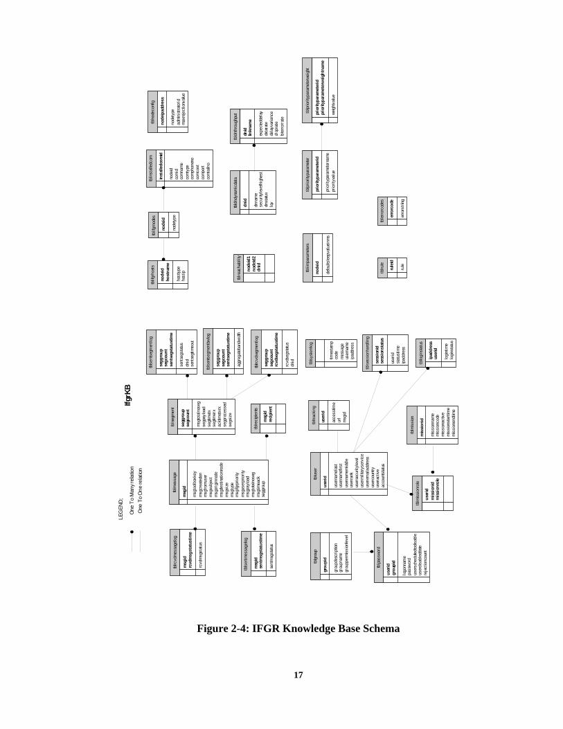
17
Figure 2-4: IFGR Knowledge Base Schema
IfgrK
BLE
GEN
D;
One
To M
any r
elat
ion
One
To
One
relat
ion
tblre
acha
bilit
y
node
id1
node
id2
dnid
tblm
issi
onro
le
user
idm
issi
onid
mis
sion
role
tblii
mpa
ram
eter
s
node
id
defa
ults
leep
valu
einm
s
tblu
ser
user
id
user
nam
elas
tus
erna
mef
irst
user
nam
emid
dle
user
rank
user
secu
rityl
evel
user
mili
tary
serv
ice
user
emai
ladd
ress
user
coun
tryus
erac
tive
acco
unts
tatu
s
tblre
cipi
ents
msg
idre
cipi
ent
tbln
odec
onfig
node
ipad
dres
s
node
type
adm
inis
trato
ridm
axre
ject
ionv
alue
tblin
stal
ledc
om
inst
alle
dcom
id
node
idco
mid
com
nam
eco
mty
peco
mph
onen
oco
mco
stco
mpo
rtco
mta
ilno
tblru
le
rule
id
rule
tbllo
gins
tatu
s
ipad
dres
sus
erid
logi
ntim
elo
gins
tatu
s
tbld
nthr
ough
put
dnid
linkn
ame
expe
cted
dela
yda
tara
tede
layv
aria
nce
drop
rate
bite
rrorr
ate
tbls
egm
ent
segg
roup
segc
ount
msg
tota
lnos
egse
gpay
load
segt
imet
xse
gtim
erx
ackt
imet
xrx
segp
roce
ssed
segs
ize
tblp
assw
ord
user
idgr
oupi
d
logo
nnam
epa
ssw
ord
user
sche
dule
dtod
isab
leus
erdi
sabl
edda
tere
ject
ionc
ount
tbld
ndyn
amic
data
dnid
dnna
me
secu
rityl
evel
high
est
dnst
atus
lqv
tblm
essa
ge
msg
id
msg
tool
boxk
eym
sgcr
eate
don
msg
from
user
msg
subj
ect
msg
orig
inno
dem
sgde
stin
atio
nnod
em
sgsi
zem
sgty
pem
sgifg
rprio
rity
msg
user
prio
rity
msg
payl
oad
msg
tota
lnos
egm
sgtim
eack
segg
roup
tblp
riorit
ypar
amet
er
prio
rityp
aram
eter
id
prio
rityp
aram
eter
nam
epr
iorit
yval
ue
tbls
entm
essa
gelo
g
msg
idse
ntm
sgst
atus
time
sent
msg
stat
us
tblg
roup
grou
pid
grou
pdes
crip
tion
grou
pnam
egr
oupp
erm
issi
onle
vel
tblp
riorit
ypar
amet
erwe
ight
prio
rityp
aram
eter
idpr
iorit
ypar
amet
erw
eigh
tnam
e
weig
htva
lue
tbls
ents
egm
entlo
g
segg
roup
segc
ount
sent
segs
tatu
stim
e
sent
segs
tatu
sdn
idse
ntse
gtim
eout
tblrc
vdm
essa
gelo
g
msg
idrc
vdm
sgst
atus
time
rcvd
msg
stat
us
tbls
essi
onha
ndlin
g
sess
ioni
dse
ssio
nsta
tus
user
idst
atus
time
ipad
dres
s
tblrc
vdse
gmen
tlog
segg
roup
segc
ount
rcvd
segs
tatu
stim
e
rcvd
segs
tatu
sdn
id
tblm
issi
on
mis
sion
id
mis
sion
nam
em
issi
onco
dem
issi
onac
tive
mis
sion
star
ttim
em
issi
onen
dtim
e
tbltr
acki
ng
user
id
acce
sstim
eur
lm
sgid
tblif
grno
des
node
id
node
type
tbls
yste
mlo
g
times
tam
pco
dem
essa
geus
erna
me
ipad
dres
s
tbls
ents
egm
entb
wlo
g
segg
roup
segc
ount
sent
segs
tatu
stim
e
aggr
egat
eban
dwid
th
tblif
grho
sts
node
idho
stna
me
host
type
host
ip
tble
rror
code
s
erro
rcod
e
erro
rstri
ng

18
2.2.7 Future Technology Enhancements Secure System Access Control: Currently, the IFGR login credentials required are a login
name and password. More rigorous authentication and access control through the use of FIPS compliant tokens, CAC cards or biometric devices needs to be integrated into IFGR to be consistent with the DoD System access policies and procedures. In addition, Secure Socket Layer (SSL) mechanisms are required to support secure transactions between the client browser and the IFGR server.
Application and End-User Support: There are number of areas that need to be enhanced in support of the war fighter’s use of IFGR. First, the IFGR User Interface has been enhanced to support the operator, however, it has not been assessed by the war fighter. Like any user interface, we anticipate the user will provide insight to the menu structure and windows that will facilitate usability of the system.
In addition, a more complete failure analysis is required such that more rigorous logging and exception handling mechanisms can be implemented. Error handling mechanisms are also used to capture data transmission requests that can not be handled by the system, whether it’s due to time, size or type, or if the transfer fails. The error reporting mechanisms notify the user via the web-based UI.
The IFGR API has been tuned to handle messages, specifically the system will proxy email with and without attachments. IFGR currently supports web access and the use of chat over the disadvantaged links however efficiency and effectiveness of the IFGR system could be improved by providing proxy capabilities for these applications. In particular, there are a number of web portals that host information needed by the war fighter but the information is presented with the assumption the war fighter is connected to a high speed land line. There are three areas that need to be addressed when developing a web proxy. First, portals typically enforce the SSL between the client and the server; second, the desired content is not always easily found from the user interface requiring a significant number of web requests and finally, web portal content is often augmented with high resolution graphics that provides minimal value to the decision making process and puts undo strain on the limited bandwidth. We propose to integrate the Web Proxy capability developed for SPAWAR by CTI that assumes major breaks in communication capabilities due to a submarine submerging. The web proxy bundles the web request to avoid the overhead typically seen with a standard web request, spidering is used to hit each URL in a given web request page and it then packages the results of the spidering i.e., web response, as an email such that it can take advantage of the store and forward capabilities of the SMTP protocol and still deliver to the user even though the initial web session is lost. We will also investigate enhancing the web proxy to automatically replace large graphics, images, sound clips, etc. with thumbnails, on which the users can click if they really want the original object. The user interface would be enhanced to include a “Web Request Preferences” page so that the user can choose whether he wants (1) the entire object, (2) a skeleton with reduced resolution thumbnails of images etc. or (3) a skeleton with ALT-TEXT descriptions in lieu of images etc. We will also investigate the users ability to retrieve the entire object when he clicks on the thumbnail or ALT-TEXT description.
We will continue to leverage AFRL’s and Capraro Tech’s efforts and experience base and investigate how the Joint Battlespace Infosphere (JBI) and DARPA’s Agent Markup

19
Language (DAML) get the right information in the right format to the right place at the right time. We will investigate the enhancing the user preferences to include information products that he would like pushed to him based upon trigger conditions (for instance, a web page each time it changes but no more often than once per hour). We will continue to investigate the integration of DAML and the use of various ontologies i.e., security and hardware in support of the UI’s adaptability to the specific device type and its display mechanism.
Error Handling and Reporting: Currently, errors that have been classified as severe, meaning the system would not work if the error occurs have been addressed. Additional error handling mechanism development is required to handle the other error types as well as a more detailed look the logging that could facilitate better error diagnostics and system recovery whether it be automatic through software or human intervention. Another area of study is what additional actions need to be taken when IFGR is brought back to a working state following a severe error i.e., what, if any, messages should be resent.
User/Mission/Link-Based Quality of Service (QoS): The IFGR QoS framework traverses all 7 layers of the OSI model. While we have
implemented prioritization mechanisms that are easily reconfigured by a user, we lack data needed to determine how best to configure the system given various architecture options and operating conditions. While simulation is not a specific technology enhancement, we believe it is imperative that we simulate the IFGR system in various configurations. Specifically, an opportunity to simulate various architectures, environmental conditions and prioritization schemes will help us deploy a more robust system.
Currently, we assume that resources will be configured for a given mission. As IFGR transitions to multiple user domains that could conceivable be tasked to the same mission where they have the opportunity to share resources such as base stations. To support a more dynamic set of users and resources, we need to investigate new methods for profile and link status setup, management and distribution such that information processing mechanisms at a given IFGR node are operating on the most current global system state information. One potential approach is the notion a presence server. Traditional presence servers used by instant messaging applications provide information about the availability of a user to communicate after the user has signed in and has been authenticated via a username and password. It keeps relatively static information like the user’s profile and preferences, along with state information (current availability and location (most likely an IP address/port) about the user.
We perceive that the IFGR presence server will use a stronger method of authentication such as a token or smartcard (not just a username and password). The presence server will access (keep track of) user information – stored to the IFGR knowledgebase via the IFGR Mission Manager when users are setup. Possibly user preferences will be stored also (buddy list, email distribution lists, etc.). And IFGR presence server will need to keep track of a user’s available (by some identifier), much the same way as a traditional Instant Messaging (IM) presence server currently does. Within the IFGR framework, we will not know precisely where the user is (IP address may be mobile). What we will know when the user is logged in, is the Home Agent node that is supporting the particular node that the user is working from. Publish and subscribe mechanisms within the IFGR system will be needed to update the presence server at a user location or a “node” as a node moves from one Home Agent to the other.

20
Intelligent data/message processing thread: The notion of an IFGR toolbox that supports multiple types of encoding, compression, segmentation, security mechanisms, etc reduces the applications burden to know how best to package it’s data over a wireless environment. We have made significant progress in the development of theIFGR toolbox and the flow of the data through it. We believe the next step is to populate the toolbox with more tools.

21
3.0 TRANSPORT LAYER
This section summarizes the activities and accomplishments with respect to performance enhancement at the Transport Layer during the IFGR contract.
3.1 GOALS AND OBJECTIVES FOR THE TRANSPORT LAYER OF THE IFGR SYSTEM
The requirement for this task was based on directives that military WANs employ the TCP/IP protocols for communication. The underlying incentive of this requirement is to benefit from use of the extensive and growing body of COTS/GOTS applications employing this suite of protocols, and to provide access to the TCP/IP-based Internet and World Wide Web (WWW).
The underlying difficulty of this requirement is that the TCP/IP protocol suite was developed for wired landlines and degrades noticeably over even moderately disadvantaged wireless SATCOM links, failing completely over severely challenged links such as those used in today’s military environment. The goal of this task was to find and incorporate COTS/GOTS Transport Layer products that were conformant with the TCP/IP protocol suite and capable of successfully communicating over degraded wireless SATCOM links
3.2 TECHNICAL APPROACH FOR THE TRANSPORT LAYER The task began with an exhaustive survey of COTS/GOTS and experimental extensions
of standard TCP. The original issues dealt with the problems caused by the severely degraded links experienced in the IFGR environment: low bandwidth, high and variable bit error rate (BER) and long and variable round-trip times.
It was decided that the only available cure for these problems in the aggregate would be to violate the fairness doctrine, which had been established on the Internet after the congestion collapse of 1987. Only The Space Communications Protocol Standard – Transport Protocol (SCPS-TP) provided the ability to forego congestion control and avoidance in favor of a pure rate control operation. This approach in IFGR is applied to only those wireless links, which belong to us and whose rate is known or can be deduced, and require no fairness to the community. This, however, is not the only reason that SCPS-TP was chosen for IFGR. It was discovered that two components of the IFGR system introduced increased latency variation and Out-of-order delivery (OOOD) of packets.
The Link Layer ARQ capability developed for IFGR, CPS, which provides enhanced reliability at the Link Layer, must, by its very nature, introduce occasional re-ordering (OOOD) of the packets of a stream of TCP packets. OOOD can significantly degrade the operation of the standard TCP residing in the IFGR endpoints, often to the point of total failure and lock-up. In addition, the CMR capability developed for IFGR to provide aggregation of multiple available wireless links of different types, thus making more bandwidth available to the TCP stream, also necessarily introduces OOOD. Only SCPS-TP offered the Selective Negative Acknowledgement (SNACK) capability, which collects packets as they arrive, no matter what order, filling in the holes in the stream as they arrive, thus shielding the IFGR endpoints from the debilitating effects of OOOD.
SCPS-TP was selected as the prime candidate for Layer 4 in the IFGR program and was then subjected to a long period of laboratory installation and testing. A SCPS-TP Gateway was

22
ported from BSD Unix to Linux, with much assistance from the SCPS-TP developers at MITRE. A test bed was constructed in the laboratory (see Figure 3.1) in which extensive testing of the SCPS-TP Gateway was performed (see Figure 3.2). Subsequently and concurrently, the Gateway was tested in the IFGR Integration and Test Laboratory in the Experimental Reachback Laboratory at AFRL Rome Site over various radio and wireless SATCOM links.
Figure 3-1: SCPS-TP Test bed
3.3 TRANSPORT LAYER ENHANCEMENTS
A SCPS-TP Gateway was been implemented in the laboratory and migrated to the IFGR/IACC. It provides seamless, transparent and automatic translation of TCP streams from LAN clients into SCPS-TP streams for transmission over wireless SATCOM links to the Warrior WAN. This gateway connects mobile warrior networks and provides warrior clients access to the mission SIPRNet/NIPRNet/Internet as designated by the mission. This capability has been successfully demonstrated in numerous field trials, exercises and on-demand demonstrations.
LINUX-2.0.36
TCPX- NISTNet Emulator
TCPX-R1 TCPX-R2
TCPX-C1 TCPX-C2
eth0
eth0 eth2
eth3
eth0
eth1 eth2
eth0
eth1 eth2
eth1
eth0
169.100.6.2
169.100.2.2 169.100.4.2
169.100.3.2 169.100.5.2
169.100.2.1 169.100.3.1 169.100.5.1 169.100.4.1
169.100.6.1 169.100.1.1
169.100.1.2 LINUX-2.2.10 or WINNT4 or WIN2000
LINUX-2.2.10
LINUX-2.2.10
LINUX-2.2.10 or WINNT4 or WIN2000

23
Figure 3-2: IFGR Transport Layer Testing Procedure
3.4 FUTURE TECHNOLOGIES AND CAPABILITIES PROPOSED FOR THE
TRANSPORT LAYER Several candidate enhancements have been identified for future SCPS-related tasks: SCPS-FP
Standard FTP, similar to TCP, suffers from the assumption that reliable wired landlines are used. The most harmful of these assumptions for the IFGR environment is that a file transfer will not be interrupted. FTP is often used to transfer large files (in the multi-megabyte range). If the link is lost or delayed significantly, the transfer must begin anew when the link is re-established. SCPS-FP can resume transmission at the point at which it was interrupted. The value of a SCPS-FP Gateway for IFGR depends on the frequency and importance of large files expected to be transmitted in the IFGR environment.
Simultaneous Operations It has been deemed desirable that the IFGR/IACC be capable of simultaneously
supporting the SCPS-TP Gateway and applications using SCPS-TP in native mode. This is more difficult and complicated to achieve than it seems at first glance.
ENVIRONMENT
SCENARIO
Windows NT 4.0/2000Windows NT 4.0/2000
LinuxLinux
SCPS-TPSCPS-TP
CombinationsCombinations
OtherOther
Imposed Scenarios
Imposed Environments
AnalysisTCPDUMPGNUPLOTXPLOTTCPTRACEDBSEtc.
Summary Analysis & Reporting
Comparative Analysis
Environment Adjustments
Scenario Adjustments
Analysis
EmulatorTools
TrafficTools
ENVIRONMENT
SCENARIO
Windows NT 4.0/2000Windows NT 4.0/2000
LinuxLinux
SCPS-TPSCPS-TP
CombinationsCombinations
OtherOther
Imposed Scenarios
Imposed Environments
AnalysisTCPDUMPGNUPLOTXPLOTTCPTRACEDBSEtc.
Summary Analysis & Reporting
Comparative AnalysisComparative Analysis
Environment Adjustments
Scenario Adjustments
Analysis
EmulatorTools
TrafficTools

24
POSIX Threads POSIX threads are the standard for multithreading applications in Linux environments
(IFGR is Linux based). The SCPS suite was developed before POSIX threads were firmly established as a standard and is consequently not compatible with applications using them to multithread. This is an issue for the SCPS program office to address, possibly with our help.
Dynamic Rate Control In the current IFGR, the existence of multiple available radio links is exploited by the
ECR capability. This provides greater effective bandwidth and increased reliability in the face of a dropped link. SCPS-TP, through its gateway_route_commander facility, can alter the rate at which each link is used.
In the present IFGR implementation, these two capabilities are de-coupled. Whereas ECR can adjust for different link rates and availability, it does not currently communicate this information to the SCPS-TP Gateway, thus it does not take advantage of the Gateway’s capability to dynamically alter its rate control mechanism. It would be advantageous to establish communication from ECR to the SCPS-TP Gateway.
Kernelizing the Gateway Standard TCP, as delivered with operating systems, operates at the kernel level, where it
is more efficient for services to operate. The SCPS-TP Gateway, as implemented in IFGR, operates in user space, causing overhead in the form of context switching and lack of access to kernel processes. For efficiency purposes and to enable sophisticated applications to control SCPS variables (e.g., rate control parameters, enabling or disabling congestion control), the SCPS-TP Gateway should be migrated to the Linux kernel.
IPv6 The IPv6 protocol is increasingly being mandated for military systems for the added
communications security it provides. With IPv6, packets are encoded and wrapped in IPv6 envelopes. Because of this, IFGR cannot currently identify the protocol of the original packet and thus cannot divert TCP packets to the SCPS-TP Gateway. This issue must be addressed in the near future.

25
4.0 NETWORK LAYER This section summarizes the activities and technical accomplishments with respect to
performance enhancement at the Network Layer of the IFGR system.
4.1 GOALS AND OBJECTIVES FOR THE NETWORK LAYER OF THE IFGR SYSTEM
A primary goal for IFGR is to achieve maximum use and efficient management of all communications resources. This goal has several implications for network layer components. Maximum use implies simultaneous and continuous access to all available communications assets. For example, when a mobile user (e.g., a user onboard an aircraft) has multiple communications channels available (e.g., HF, UHF Line-of-sight, and UHF SATCOM), all channels should be leveragable to improve the user’s overall ability to move data as quickly and efficiently as possible. This is particularly true in low data rate environments (e.g, 2400 bits per second), where being able to treat disparate, individual low data rate channels essentially as a single channel with a substantially higher data rate provides significant advantages for timely delivery of high priority information.
Coupling of maximum use with efficient management implies the use of resource sharing in order to keep the communications channels fully utilized. If instead resources are not shared, but rather individual users or applications are assigned fixed allocations of some portions of the channel resources regardless of whether the allocated resources are actually needed at any given time, inefficient delivery clearly results. For example, consider a fixed apportioning between a high priority user and a low priority user. With a fixed scheme, the low priority user with significant amounts of data to move might only be allotted a small fraction of the available resources, even when the higher priority user has absolutely no current delivery needs. Ideally, high priority transfers are given access to the full set of resources when needed, and lower priority transfers are given access to the full set of resources when no higher priority transfers are enqueued. Note that we distinguish between transfers and users here, in that not all transfers by a high priority user will necessarily be of high priority, such that assigning priorities to transfers (vs. applications or users) allows IFGR to optimize mission effectiveness across multiple missions.
4.2 TECHNICAL APPROACH FOR THE NETWORK LAYER
The following discussion reviews the technical approach taken to realize IFGR Network Layer goals and selected capabilities.
4.2.1 Concurrent Multipath Routing (CMR): Simultaneous Use of All Assets In the telecommunications industry, the transparent aggregation of separate data links to
form what appears to be a single, higher bandwidth data link is known as inverse multiplexing. IFGR performs a similar type of transparent aggregation at the network layer using a technique known as Concurrent Multipath Routing (CMR). CMR provides the basic means for distributing outbound traffic across alternate paths through a network, with path selection based on a set of weights, one weight for each path. Paths with higher weights receive proportionately greater amounts of traffic; paths with smaller weights receive proportionately less. By setting weights appropriately, the traffic distribution to the individual links is tailored to match the bandwidths of the links as shown in Figure4.1.

26
Figure 4-1: CMR allows simultaneous use of all available communication links
The Linux CMR implementation allows either a per-flow path selection mode or a per-
packet path selection mode for splitting traffic across multiple channels. Per-flow path selection works by choosing one of the available paths upon the origination of a session (for example, as defined by the usual bind 5-tuple semantics which includes source and destination addresses, source and destination ports, and protocol), and using only that path for the duration of the session. Per-packet path selection differs in that path selection is performed for each packet individually.
The clear advantage of using per-packet path selection is that the highest priority data can be delivered in parallel ahead of any competing delivery. Consider for a moment a situation where a high priority delivery is assigned to one of two available equal bandwidth channels using a per-flow selection approach, with a very short, higher priority delivery assigned to a third, much higher bandwidth channel. First we note that in the absence of other outstanding deliveries the remaining channel will go unused, providing a clear waste of resources. Moreover, once the shorter, higher priority delivery completes, the remaining high priority delivery will continue to use only its assigned lower priority channel, such that the highest bandwidth link will either go unused or be used for delivering lower priority traffic. A per-packet based selection approach avoids these problems, as all resources can be fully utilized for any given delivery.
The downside to using per-packet selection is the potentially large variations that can occur in delivery latency along the different paths, resulting in out-of-order delivery (OOOD) and large round trip time (RTT) variances, both of which can negatively affect the throughput of transport protocols such as TCP. However, this problem can be mitigated using a variety of techniques, which including preemptive path equalization or enhanced transport protocols, such as the Space Communications Protocol Suite (SCPS). Because of the clear advantages and the quite manageable disadvantages, per-packet path selection is the CMR technique used within IFGR.
DoD IP Network
IFGR Ground Support
Third Party Data Sources
User (Data Sink)
2400 bps 4800 bps
9600 bps
2400 bps
19,200 bps
192.167.1.10
192.167.1.1
202.16.23.3 202.16.23.4
130.6.47.2
147.81.29.7
67.7.129.4
CMR makes multiple paths to and from the aircraft appear as one “connection” to upper
layers (e.g., applications)
27
4.2.2 Explicit Channel Reservation (ECR): Prioritized Access to Comm Assets The ability to prioritize and coordinate data delivery among multiple competing demands
also requires some form of resource management system. The upper layers of the resource management process, including those functions controlling delivery classification, prioritization, and regulation (start/stop operations, delivery rate, etc.) are localized within the Intelligent Information Manager (IIM) and its interactions with transport layer (e.g., TCP) and/or application layer (e.g., SMTP) components. At the lower layers, some mechanism is needed for coordinating the actual resource usage. Here, at least two design alternatives are possible. One alternative is to use a single, monolithic IIM that is the sole gateway into IFGR. With a single point of control, a monolithic IIM can in principle provide comprehensive prioritization of outstanding delivery requests against all available resources on a continuous basis in order to globally optimize the system utility function (e.g., mission effectiveness). Under the assumption that the terrestrial infrastructure is many orders of magnitude faster (and correspondingly has orders of magnitude less delay) than the wireless links, a centralized approach might in fact represent a workable solution.
The downside of a centralized solution is that it not only induces a single point of failure (resulting in a fragile design, and making it an extremely high value target for potential cyber attacks), but it also scales poorly as wireless link speeds increase. In particular, the processing overhead needed to control traffic on a global basis could easily become excessive and ultimately pose a critical bottleneck. Moreover, with higher speed links, the delivery latencies over the wireless component become sufficiently small that terrestrial propagation and queuing delays over long distances (e.g. Asia to CONUS back to Asia with a centralized approach) can in fact become the dominant factor affecting overall system efficiency.
An alternate approach is to allow multiple distributed IIMs to operate essentially independently, with prioritized access to individual wireless resources coordinated through a distributed resource reservation system. The resource reservation approach developed for IFGR is referred to as Explicit Channel Reservation (ECR).
The notional view of ECR operations is that there are multiple IIMs, essentially one for each aircraft1 that at any given time have an outstanding set of prioritized items to deliver. Nominally, each item may be thought of as a file, a mail message, or a web page that the IIM has been tasked with delivering to its respective aircraft (although “items” may be streaming media such as voice or video rather than simple document files). Upon receipt of each delivery request, the IIM makes a reservation request to a local ECR agent (known as the Application Support Agent, or ASA) which in turn distributes the request to one or more remote access management agents (known as Link Management Agents, or LMAs), where each agent is associated with a wireless communication link that can be used to reach the aircraft at that point in time. As part of the request, the IIM provides a scalar priority value assigned to the request, and a set of related descriptive information such as transfer size (for file-based transfers), minimum and maximum bandwidths (for streaming services), and delivery deadlines (beyond which the delivery of the data will provide no value to the recipient). Each LMA queues up the outstanding set of requests
1 A single ground based IIM can, in general support several aircraft simultaneously, but in general will not support all aircraft simultaneously.

28
from multiple IIMs, assigns in turn resources to the current highest priority request, and notifies the appropriate ASA of the resource allocation. Upon receipt of one or more resource allocation notifications, the ASA hands of the resource allocation up to its associated IIM to begin delivery of the item. Upon completion of the delivery, the IIM notifies ECR by retracting the associated reservation requests, thereby freeing any allocated assets for subsequent assignment to the next highest priority requests. An example showing ECR operation is provided in Figure 4.2 below.
Policy-based Resource Allocation – A variety of considerations, such as the need for preemption (to allow newly arrived ECR requests with higher priority to have immediate access to available resources) and priority promotion (to prevent lower priority requests from being delayed indefinitely because of a continual influx of higher priority requests) have motivated the development and incorporation of a highly flexible, policy-based asset management system within the ECR LMA. Since at this time it is unclear what even a “suboptimal” allocation policy may be, or even what the Air Force may ultimately decide to use as an allocation policy, we have identified a fairly broad range of allocation control mechanisms to enable flexible traffic delivery, including:
• Priority range (M to N, inclusively) and interpretation (whether the lower value M or the higher value N has “highest” priority)
• Hold limits (to constrain the amount of time any given allocation may hold a reservation)
• Intra-priority bandwidth sharing to allow equal priority requests from different aircraft to run concurrently, with equal sharing of the bandwidth
• Inter-priority bandwidth sharing to allow requests with different priority to run concurrently, with proportionate sharing of the bandwidth
• Priority promotion to allow lower priority requests to effectively take on increased priority over time, thereby avoiding complete starvation of lower priority requests.
• Preemption to allow higher priority requests to take precedence over lower priority allocations already in place by temporarily retracting the lower priority allocations.
• Cost to allow IIMs to limit the use of expensive, non-Government owned links to only those occasions when urgent or high priority mission needs can justify the attendant costs in preference to links with little or no associated costs for more routine mission needs.
Initially message one (MSG1) is being transferred from DS2 to MN2 when a second message (MSG2) is queued for delivery from DS1 to MN1 (upper left). Example shows sequence leading to allocation of parallel data paths for delivering MSG2 after delivery of MSG1 is complete.
To facilitate decision making by the IIM, ECR also supports a “probe” capability whereby an IIM can query the routing and QoS infrastructure to obtain what is referred to as a “rate and expected delay” vector. Here, the IIM essentially submits an identically formulated pseudo reservation request to ECR containing the data delivery characteristics in order to find out a) how many links are available to reach a given destination; b) what the expected data rate would be on each link if a reservation were to be granted, and c) what the expected wait time (delay) would be before the reservation would be granted on each link. ECR evaluates the pseudo reservation request against both the set of outstanding reservations in the reservation

29
queue as well as the allocated or granted reservations to determine the effective position in the reservation (or granted) queue of the pseudo reservation by applying its local policy. ECR then calculates the expected wait time using both the declared delivery sizes of items ahead of the pseudo reservation in the reservation queue and the (recently) observed link performance.
Figure 4-2: Example ECR Operation
FA1 FA2
MN1 MN2
HA2HA1
DS1 DS2
Queued Sending
CMR WgtsFA1FA2
CMR WgtsFA1FA2 0
N/A
Queued AllocatedHA2
Queued SendingMSG2
16
Queued AllocatedHA2
16
FA1 FA2
MN1 MN2
HA2HA1
DS1 DS2
Queued Sending
CMR WgtsFA1FA2
CMR WgtsFA1FA2 0
N/A
Queued AllocatedHA2
Queued SendingMSG2
16
Queued AllocatedHA2
16
FA1 FA2
MN1 MN2
HA2HA1
DS1 DS2
Queued Sending
CMR WgtsFA1FA2
CMR WgtsFA1FA2 0
N/A
Queued AllocatedHA2
Queued SendingMSG2
16
Queued AllocatedHA2
16
FA1 FA2
MN1 MN2
HA2HA1
DS1 DS2
Queued SendingQueued Sending
CMR WgtsFA1FA2
CMR WgtsFA1FA2
CMR WgtsFA1FA2
CMR WgtsFA1FA2 0
N/A
Queued AllocatedHA2
Queued AllocatedQueued AllocatedHA2HA2
Queued SendingQueued SendingMSG2
1616
Queued AllocatedHA2
Queued AllocatedQueued AllocatedHA2HA2
1616
FA1 FA2
MN1 MN2
HA2HA1
DS1 DS2
Queued Sending
CMR WgtsFA1FA2
CMR WgtsFA1FA2 0
N/A
Queued AllocatedHA2
Queued SendingMSG2
16
Queued AllocatedHA2
16
FA1 FA2
MN1 MN2
HA2HA1
DS1 DS2
Queued SendingQueued Sending
CMR WgtsFA1FA2
CMR WgtsFA1FA2
CMR WgtsFA1FA2
CMR WgtsFA1FA2 0
N/A
Queued AllocatedHA2
Queued AllocatedQueued AllocatedHA2HA2
Queued SendingMSG2
Queued SendingQueued SendingMSG2
1616
Queued AllocatedHA2
Queued AllocatedQueued AllocatedHA2
1616
FA1 FA2
MN1 MN2
HA2HA1
DS1 DS2
Queued Sending
CMR WgtsFA1FA2
CMR WgtsFA1FA2 16
N/A
Queued AllocatedHA2
Queued SendingMSG2
1616
Queued AllocatedHA2 HA1
MSG1
FA1 FA2
MN1 MN2
HA2HA1
DS1 DS2
Queued Sending
CMR WgtsFA1FA2
CMR WgtsFA1FA2 16
N/A
Queued Allocated
Queued Sending
00
Queued AllocatedHA1
MSG1MSG2
FA1 FA2
MN1 MN2
HA2HA1
DS1 DS2
Queued Sending
CMR WgtsFA1FA2
CMR WgtsFA1FA2 16
N/A
Queued AllocatedHA2
Queued SendingMSG2
1616
Queued AllocatedHA2 HA1
MSG1
FA1 FA2
MN1 MN2
HA2HA1
DS1 DS2
Queued SendingQueued Sending
CMR WgtsFA1FA2
CMR WgtsFA1FA2
CMR WgtsFA1FA2
CMR WgtsFA1FA2 16
N/A
Queued AllocatedHA2
Queued AllocatedQueued AllocatedHA2HA2
Queued SendingQueued SendingMSG2
16161616
Queued AllocatedHA2 HA1
Queued AllocatedQueued AllocatedHA2 HA1
MSG1
FA1 FA2
MN1 MN2
HA2HA1
DS1 DS2
Queued Sending
CMR WgtsFA1FA2
CMR WgtsFA1FA2 16
N/A
Queued Allocated
Queued Sending
00
Queued AllocatedHA1
MSG1MSG2
FA1 FA2
MN1 MN2
HA2HA1
DS1 DS2
Queued SendingQueued Sending
CMR WgtsFA1FA2
CMR WgtsFA1FA2
CMR WgtsFA1FA2
CMR WgtsFA1FA2 16
N/A
Queued AllocatedQueued AllocatedQueued Allocated
Queued SendingQueued Sending
0000
Queued AllocatedHA1
Queued AllocatedQueued AllocatedHA1
MSG1MSG2

30
Comparison of ECR With RSVP – The ECR capability developed for IFGR differs substantially from alternate reservation mechanisms, including the well-known ReSerVation Protocol (RSVP). For illustration, some of the key differences between ECR and RSVP include:
• Sender-based vs. Receiver-based – In RSVP, reservations are issued by receivers in response to sender advertisements, whereas in ECR reservations are issued directly by the senders. Use of RSVP would require sending advertisements and reservations across the wireless link, needlessly adding overhead, when in fact the reservations need only be exchanged between the IIM and the base station. Hence ECR uses a sender-based reservation style.
• Reliable Signaling vs. Best Effort Signaling – In RSVP, reservations are sent hop-by-hop using best-effort transport (i.e., using UDP), whereas in ECR reservations are sent reliably end-to-end (i.e., using TCP). Since in RSVP the reservations are issued by the receiver, receipt of the reservation at the sender acts as a type of acknowledgement of the senders advertisement, and is sufficient to start data flowing; however, reservations may be lost in transit, resulting in setup delays or possibly even loss of service. Use of reliable transport assures that ECR state is accurately known at each end, and that setup is timely and guaranteed.
• Aggregate Path vs. Single Path Reservations – The single greatest impediment for using RSVP is its lack of support for CMR, i.e., allowing the intentional setup of multiple reservations along potentially quite different paths to reach the same receiver. Support for CMR is an essential and critical characteristic of ECR.
• Queued Reservations vs. Demand-based Reservations – In RSVP, reservations are demand-based, where requests have no persistence (i.e., responses are issued immediately or not at all), and responses are Boolean (yes or no). Hence reservations are purely first come, first served, with no ability to retain, prioritize, or select from a number of outstanding reservation requests made at an earlier time, and with no ability to describe the allocated resources (e.g., assigned bandwidth). ECR retains all reservation requests issued by IIMs until they are accepted or retracted by IIMs, and responds with a full characterization of the assigned resource. The ability to queue requests and described allocated resources is essential for ECR to provide prioritized resource allocation and coordinate resource usage among competing IIMs. Note that without queued reservations, it is impossible to estimate potential priority induced delays in support of the ECR’s “probe” feature described earlier.
ECR Support for CMR Operations – As described earlier, CMR uses the notion of link weights to apportion traffic among the individual links. For CMR to be truly responsive in an IFGR-like environment, dynamic management of weights is required to reflect the potentially highly volatile nature of wireless link bandwidths. As ECR provides a means for describing assigned resources in its reservation responses, and hence can be used to assign bandwidth dynamically (e.g., as sensed by any Link Quality Assessment (LQA) operations) as well modify assignments on-the-fly using ECR’s intrinsic preemption capabilities. Hence ECR provides the core mechanism for dynamically setting CMR weights, as well as affecting a type of admission control system through the use of weight values of zero. (Note: here, assigning a weight of zero to an interface implies that no data should be sent to that interface.)

31
CMR Enhancements In Support of ECR – Several relatively minor modifications have been made to the CMR implementation distributed with the Linux kernels both to improve its overall performance within IFGR as well as provide better support for ECR operations. Specifically, the base CMR distribution only allows weight values within the range of one to 256 inclusive, and does not allow weights with a value of zero. As described above, weights with value zero are useful for identifying paths for which valid routes exist but currently have no resources assigned, and hence are essential for separating routing operations (path establishment) from reservation operations (path admission). The base CMR distribution also does not support immediate on-the-fly weight adjustments (as needed for incremental resource allocation, preemption, and dynamic bandwidth adjustment) but rather requires waiting for a cycle to complete for any new weight assignments to take effect. (Note: a cycle is defined here to be the transmission of a number of packets equal to the sum of all weights assigned to the given set of CMR paths.) Support for zero-valued weights and the attendant discard of packets when all weights are set to have zero value, as well as needed modifications to the interface selection algorithm to allow on-the-fly weight adjustments while preserving improved short-term statistical properties, have already been incorporated within the IFGR kernel code.
4.2.3 Mobile IP: Transparent, and Seamless Mobile Networking At the network layer in standard Internet Protocol (IP) networks, IP routers forward
packets based on each packet’s destination IP address, with forwarding decisions based on information contained within each router in the form of routing tables. For efficiency, routes within routing tables are typically specified and stored as groups of IP addresses known as subnets rather than as long lists of individual hosts. For this subnet-based approach to work, 1) each IP address within a subnet must be reachable along the same path, and 2) the last router along the delivery path to a given host must be able to communicate directly with that host. Combining this set of observations and requirements yields the commonly held view that a host’s IP address in general specifies its point of attachment within the network2. This implies that using traditional routing approaches, a new, locally compatible IP address must therefore be assigned to and used by a mobile host whenever it changes its point of attachment3. This is known as the mobility problem, as illustrated in Figure 4-3.
At the transport layer (where TCP operates), seamless application operation requires a fixed IP address on each side of a connection for the duration of the connection. This is due to the transport layer’s use of both endpoint IP addresses as part of the state information used to identify the connection. If the IP address of one end, say a mobile host, were to change in mid-transfer due to a change in network connectivity, the existing transport layer connection would be broken. Once the transport layer connection is lost, a new transport layer connection must be initiated using the new IP address pair before communications may resume. Thus, the network layer requirement that mobile user’s address must change when changing points of attachment directly conflicts with the transport layer requirement that the address stay the same. In
2 Although individual host entries can be specified within host tables, and can in fact be propagated using dynamic routing protocols, routing updates happen far too infrequently – typically on time scales measured in hours – for dynamic routing to provide an effective solution to for mobile hosts. 3 Protocols such as DHCP (Dynamic Host Configuration Protocol) are designed to perform this function, assigning IP addresses from the local subnet to any locally attached computer requesting one.

32
particular, maintaining a fixed mobile host address is a hard requirement for almost every IP-based legacy application.
Figure 4-3: Changing points of attachment makes a mobile user unreachable with
traditional IP routing To further complicate the connectivity issue, there are also at least two frequently used
services that are broken if a mobile user changes IP addresses. The first is the Domain Name Service (DNS), which is designed to resolve a Fully Qualified Domain Name (FQDN) of a host (e.g. www.yahoo.com) into one or more IP addresses and vice versa. Every time a mobile user’s IP address changed, the DNS database entry for the mobile user would require an update. However, most applications typically resolve a FQDN into an IP address only once during startup, which will defeat any DNS updates. Also, DNS is a critical service in most networks that simply cannot be put at risk by frequent automated updates to its database. The second network “service” that may be broken is any application that must initiate a connection to the mobile user, rather than the mobile user initiating the connection. An example of this would be a web server running on a mobile host. If a mobile host’s IP address changes, then it will no longer be reachable in order to initiate the data transfer.
Mobile IP (ref. RFC 3220) provides a standards-based solution for the mobile routing problem. (For convenience, we henceforth refer to Mobile IP by its common abbreviation, MIP.) MIP is an automatic, dynamic route maintenance mechanism that allows a mobile host (called a mobile node) to retain and use its assigned address from its home network (i.e., its home address) even as its point of attachment to the network changes. Allowing a mobile node to retain its home IP address satisfies the above transport layer and DNS requirements as well as allowing the mobile node to be contacted at any time from a third party which is otherwise unaware that the node is in fact mobile. We note here that multiple open-source implementations of MIP are available for Linux, and at least one implementation (the SUNY Binghamton code set and derivatives) does not require any Linux kernel modifications4.
MIP works as follows. The mobile node first obtains an IP address (termed the care-of address) from the foreign network that can be used to reach the mobile node via the foreign
4 To minimize code maintenance overhead as well as desensitize IFGR to changes in future Linux kernel releases, the latter implementation was selected as the basis for MIP capabilities being developed for IFGR. Nonetheless, this code basis has undergone rather dramatic changes to make the code robust as well as to support IFGR’s advanced features.
Ongoing data delivery addressed to node’s
home addressMobile Node
Home Subnet:192.167.1.0
Remote Subnet:204.1.1.0
Third Party Data Source
Intermediate Links
Intermediate Routers
Home address: 192.167.1.10
Link broken, delivery disrupted
?
Home Subnet:192.167.1.0
Remote Subnet:204.1.1.0
Third PartyData Source
Home address: 192.167.1.10
Link connectivity, but no route: subnets are incompatible

33
network. The mobile node then registers the address with a MIP support entity on its home network, known as the home agent, forming what is known as a mobility binding. The mobility binding authorizes the home agent to capture packets on the home network addressed to the mobile node’s home address and forward them to the specified care-of-address. The MIP process then becomes one of the mobile node updating its mobility binding whenever its point of attachment changes. When the mobile node returns to its home network it simply deregisters its mobility bindings, thereby resuming normal network operations. Note that when the mobile node is away from its home network, the mobile node still uses its home address as the source address for any packets it originates. Similarly, all packets destined for the mobile node still use the mobile node’s home address as the destination address. Hence from the point of view of any third party hosts, no changes are needed to any legacy applications or network configurations as the mobile node appears to be on its home network (except for any attendant side effects such as increased latency).
The forwarding of packets from the home network to the mobile node is accomplished using IP encapsulation, i.e., via an IP-in-IP tunnel. The home agent performs IP encapsulation by placing the original IP packet inside another IP packet, with the destination address within the encapsulation header set to the mobile node’s care-of address. Doing so then allows the encapsulated packet to be routed to the foreign network where the mobile node is currently attached. Note that the home agent controls proxy-ARP, tunnels and routing tables in the kernel to forward packets to the mobile node and does not directly process each packet. When the encapsulating IP packet reaches the host having the care-of address it is de-encapsulated (the outer IP packet is removed), revealing the original IP packet, which is then delivered to the mobile node. Figures 4-4 and 4-5 illustrates the relationship between the various entities when the mobile node is home and when it is traveling for MIP operating in co-located addressing mode, one of its two basic operating modes, as described in the next paragraph.
A MIP care-of address may either be a borrowed address assigned to the mobile node itself (e.g, as obtained from a DHCP server located on the foreign network, as shown in Figure 4.4) or the address of a MIP support entity on a foreign network, commonly referred to as a Foreign Agent. Use of a borrowed address is generally referred to as co-located mode, whereas use of a Foreign Agent is referred to as mobility support mode. To help clarify the presentation here, we instead refer to mobility support mode as Foreign Agent mode. The primary difference between the two modes is that the co-located care-of addressing mode requires the mobile node to deencapsulate the arriving packets itself, whereas the Foreign Agent performs the deencapsulation in Foreign Agent mode. MIP operations in Foreign Agent mode is shown in Figure 4.5.

34
Figure 4-4: Mobile IP (MIP) operations in Co-located mode
Figure 4-5: Mobile IP operations using mobility support (Foreign Agent) addressing
mode While either type of care-of addressing is potentially workable within the IFGR
architecture, clear differences between the two modes motivate the use of Foreign Agent care-of-addressing for IFGR. To clarify the trades involved, we first note that co-located care-of addressing requires the mobile node to obtain (or “borrow”) an address that is compatible with the foreign network (e.g., using DHCP) before the registration process can begin. Obtaining the address adds configuration delays and control traffic over the low-bandwidth wireless links. Moreover, since deencapsulation occurs at the mobile node with co-located addressing, sending
Mobile Node 192.167.1.10
(At Home)
Third Party (Mobile IP Unaware)
Home Agent 192.167.1.15
(Inactive)
Traffic to and from 192.167.1.10
“I’m 192.167.1.10”
Home Network Router
192.167.1.1
Internet Router(s)
Mobile Node at Home Mobile Node Traveling
“Traveler, use Care-of-address
204.1.1.20”
Mobile Node 192.167.1.10 (Traveling)
Home Agent192.167.1.15
(Active)
Foreign Agent 204.1.1.20 (Active)
Third Party (Mobile IP Unaware)
Traffic to 192.167.1.10
“192.167.1.10 can be reached via
204.1.1.20”
“I’m 192.167.1.10”
Decapsulated traffic forwarded to 192.167.1.10
Traffic for 192.167.1.10 tunneled to 204.1.1.20
Traffic from 192.167.1.10
Mobile Node192.167.1.10
(At Home)
Third Party (Mobile IP Unaware)
Home Agent192.167.1.15
(Inactive)
Traffic to and from 192.167.1.10
“I’m 192.167.1.10”
Home Network Router
192.167.1.1
Internet Router(s)
Mobile Node at Home Mobile Node Traveling
Traffic from 192.167.1.10
“I’m 192.167.1.10”
Traffic to 192.167.1.10
Foreign Agent204.1.1.20(Inactive)
Third Party (Mobile IP Unaware)
“192.167.1.10 can be reached at
204.1.1.24”
Traffic for 192.168.1.10 tunneled to 204.1.1.24
“Traveller192.167.1.10,
borrow address 204.1.1.24”
– from DHCP
Home Agent192.167.1.15
(Active)
Mobile Node192.167.1.10(Traveling)
Mobile Node192.167.1.10
(At Home)
Third Party (Mobile IP Unaware)
Home Agent192.167.1.15
(Inactive)
Traffic to and from 192.167.1.10
“I’m 192.167.1.10”
Home Network Router
192.167.1.1
Internet Router(s)
Mobile Node192.167.1.10
(At Home)
Third Party (Mobile IP Unaware)
Home Agent192.167.1.15
(Inactive)
Traffic to and from 192.167.1.10
“I’m 192.167.1.10”
Home Network Router
192.167.1.1
Internet Router(s)
Mobile Node at Home Mobile Node Traveling
Traffic from 192.167.1.10
“I’m 192.167.1.10”
Traffic to 192.167.1.10
Foreign Agent204.1.1.20(Inactive)
Third Party (Mobile IP Unaware)
“192.167.1.10 can be reached at
204.1.1.24”
Traffic for 192.168.1.10 tunneled to 204.1.1.24
“Traveller192.167.1.10,
borrow address 204.1.1.24”
– from DHCP
Home Agent192.167.1.15
(Active)
Mobile Node192.167.1.10(Traveling)
Traffic from 192.167.1.10
“I’m 192.167.1.10”
Traffic to 192.167.1.10
Foreign Agent204.1.1.20(Inactive)
Foreign Agent204.1.1.20(Inactive)
Third Party (Mobile IP Unaware)
Third Party (Mobile IP Unaware)
“192.167.1.10 can be reached at
204.1.1.24”
Traffic for 192.168.1.10 tunneled to 204.1.1.24
“Traveller192.167.1.10,
borrow address 204.1.1.24”
– from DHCP
Home Agent192.167.1.15
(Active)
Home Agent192.167.1.15
(Active)
Mobile Node192.167.1.10(Traveling)
Mobile Node192.167.1.10(Traveling)

35
encapsulated IP packets over the wireless links adds a 20 byte overhead to each packet due to the additional IP header (IP version 4, in the absence of any advanced header compression5).
In contrast, using Foreign Agent care-of addresses eliminates the need to borrow a foreign address, which obviates the attendant configuration delays and overhead traffic on the wireless links. Additionally, and perhaps more importantly, with foreign agent care-of addressing, packets are deencapsulated by the Foreign Agent before being sent across the wireless links, eliminating encapsulation overhead. The relatively small downside to this approach is that the Foreign Agents must periodically advertise the Foreign Agent service, which does consume wireless bandwidth; however, the ICMP advertisements are quite small and can be issued relatively infrequently. Overall, using MIP with foreign agent care-of addressing offers clear performance advantages for IFGR.
The availability of the Foreign Agent also provides resources needed to support ECR operation at a critical location in the network. Specifically, the host running the Foreign Agent is directly connected to the wireless interface (in a routing sense at least) and so is ideally located to affect admission control and inter-aircraft prioritization of resource requests. Moreover, the host running the Foreign Agent can be used to detect link loss and automatically deallocate any allocated resources (via ECR) far faster than the MIP deregistration process can be performed using MIP’s usual discovery cycle. This avoids needless tying up of resources only to transmit packets to an aircraft that is no longer reachable over a given link. Although these services could in fact be provisioned in the necessary hosts without requiring the use of Foreign Agent care-of addressing (or in fact without requiring MIP at all), it is highly desirable for such hosts to be automatically “discoverable” rather than preconfigured in static tables since the maintenance and distribution of such tables present a significant management problem. The co-location of the MIP foreign agent in the host providing these services conveniently solves the automatic discovery problem, since the normal MIP registration process for Foreign Agent care-of addressing provides all needed discovery information.
The Foreign Agent also provides as a convenient point of origin for a reverse IP-in-IP tunnel from the aircraft to the Home Agent. Historically, one of the problems associated with MIP is its “triangle routing characteristic”, whereby traffic flowing from the aircraft to the sender on the ground was not required to flow back through the Home Agent. This posed several challenges, including the oft cited problem of differential path latencies (i.e. the path from the ground to the aircraft could have quite different latency from the path from the aircraft to the ground) which could easily give rise to poor TCP performance. By forcing the traffic from the aircraft to the ground sender to flow back through the Home Agent, reverse tunnels help equalize delivery latency variations amongst the multiple wireless links. Reverse tunnels also provide a
5 Standard header compression techniques can be used here to reduce the size of IP encapsulation headers, however these techniques can also be applied equally well to unencapsulated packets with foreign agent care-of addressing. Hence the net difference in packet size between the two approaches essentially remains the same. An advanced header compression technique for encapsulated packets can be envisioned that could also reach into the payload of encapsulated packets to compress the header of the embedded packet; however, such techniques do not yet exist. Moreover, information theoretic arguments can be made to show that compressed encapsulated packets must always be larger than unencapsulated packets compressed using an optimal compression scheme, since the encapsulated packet is always a proper superset of the unencapsulated packet.

36
means for traffic from the aircraft to traverse any routers between the Foreign Agent and the third party ground sender that may be running ingress filtering firewalls6. Most importantly, however, reverse tunnels are absolutely critical for making transparent transport layer gateways (such as the SCPS gateway we are using in IFGR to improve TCP performance over multiple disparate links) work correctly. Without reverse tunnels, traffic flowing from the aircraft to the ground will in general not flow through the gateway host, such that the gateway is unable to interpose itself between the aircraft source and the ground destination in order to “hide” the link behaviors and provide improved TCP performance.
We add here that normally reverse tunneling, if used with MIP, originates at the mobile node (i.e., the aircraft); however, originating the reverse tunnel at the ground again avoids incurring the IP-in-IP overhead over the wireless link. Although the reverse tunneling support origination at Foreign Agents is at odds with the current MIP standard, it is used within IFGR because of the clear performance advantages.
Additional IFGR-specific MIP Enhancements – One of the goals of IFGR is providing a transparent networking capability where individuals with their own computing equipment can simply walk on to an IFGR-equipped aircraft, connect to the aircraft LAN, and be able to use the IFGR network without requiring any special software or extensive reconfiguration of their equipment. There are at least two requirements implied by this goal. The first involves supporting what will henceforth be referred to as “unmanaged” traffic within the IFGR system, where an individual wants to use some network-enabled application for which there is currently no equivalent IFGR proxy. Support for unmanaged traffic is discussed in the section entitled “IFGR Networking Component Enhancements”. The second requirement implies that IFGR provide a means to use what is normally thought of as the mobile node as a gateway between the user equipment and the wireless infrastructure, which we now discuss.
There are several means for using the IFGR mobile host as a mobile router, all of which are supportable in the current IFGR network component implementation. The simplest involves configuring the mobile host as a router running Network Address Translation (NAT), and enabling it to hand out private (non-routable) addresses to the user equipment using DHCP. Although the use of private addressing generally prevents third parties on the terrestrial side of the wireless link from originating connections to the individual user equipment, the airborne user can in general seamlessly and freely originate contact with any third party on the terrestrial side. The only requirement on the user host for this approach to work is that the user equipment must be configured as a DHCP client, a capability intrinsic to nearly all modern network-enabled
6 Modern security practices recommend that enterprise routers discard any packet that has a source address which is inconsistent with the interface that the packet arrived on. Here, “inconsistent” means that a route lookup by the router to forward a hypothetical packet back to the given source address returns a different interface than the one on which the packet in question was actually received. Since a mobile node uses its home address as the source address for all outbound packets, ingress checks anywhere along much of the forwarding path will likely indicate the packet appears to be arriving on the wrong interface, resulting in packet discard. Establishing a reverse IP-in-IP tunnel between the foreign agent and the home agent solves this problem as the encapsulated packet instead appears to be originating from the foreign agent, which will then pass any ingress checks. Once at the home agent, the packet may safely be deencapsulated and forwarded to the third party in the usual way, since the decapsulated packet now appears to be originating from the home network and will have an address consistent with the remainder of the forwarding path.

37
operating systems. This approach adds no packet overhead on the wireless links, since the mobile node’s address is transparently substituted for the private address within the mobile node for outbound traffic, and is reinserted into any inbound traffic destined for the user equipment. We note, however, that correctly inserting private addresses into inbound packets can be a complicated operation with some network applications, and a NAT based solution may require inserting specialized support modules in the mobile node for the user application to work correctly (the familiar ftp application is an example of this). Hence use of NAT is not a completely robust solution, but in fact is quite workable and has been successfully demonstrated over the IFGR infrastructure.
A second approach that provides a more robust solution as well as supporting third party connection origination requires extending MIP to allow a mobile node to register a range of public addresses (i.e., a subnet) with the Home Agent rather than the usual single public address of the mobile node. This in effect allows the Home Agent to capture and forward traffic addressed to any address within the subnet range, effectively turning the mobile node into a mobile router. This capability, described as a MObile NETwork (or MONET) by the IETF Network Mobility (NEMO) Working Group, has been developed for IFGR by extending the IFGR MIP implementation using the RFC 3320-specified approach for extending MIP. With this capability, the mobile host then need only hand out addresses from this assigned subnet range (e.g., using DHCP) to the user equipment and be configured as a router in the usual way. As with NAT, the only requirement on the user equipment for this to work is that the user equipment must be configured as a DHCP client. This approach also adds no packet overhead on the wireless links, and since no address translation is involved, provides a considerably more straightforward and robust solution. This second approach is the approach currently used within IFGR.
A third approach that is both more complicated and less efficient involves configuring the mobile host itself to act as a MIP foreign agent. With this approach, the user host is itself configured as a mobile node and must have an associated home agent providing MIP support on its home network. The user host would then register the home address of the mobile node as its Foreign Agent care-of address with its associated home agent, essentially running MIP over MIP. Although this has not been tested in our IFGR testbed, it is conceptually straightforward and should work over the current IFGR infrastructure without requiring further modifications to MIP, ECR, or CMR. This particular approach offers the unique advantage that the user host can continue to use its normal home address rather than a borrowed address, so that any services normally offered by the user host on its home network (such as web services or database services) can continue to be offered to third parties in a completely transparent fashion. However, there are also several disadvantages to this approach, including both increased overhead (not only must encapsulated packets destined for the user host at least reach the mobile node before de-encapsulation can occur, but the user host must also maintain registration with its supporting home agent, imposing additional traffic) as well as the inability to make use of IFGR’s priority-based resource management system (since proxy services generally do not understand encapsulated traffic). Workarounds for both of these disadvantages are certainly possible; however, any such workarounds will necessarily add significant cost and complexity to the system, and must be weighed against the potential benefits afforded by this third approach.

38
MIP Interoperations With CMR – MIP as defined in RFC 3220 does not support CMR per se, but it does allow simultaneous bindings, one binding per path. The subtle difference between the type of simultaneous bindings required for CMR and the type of simultaneous bindings allowed within the MIP specification is that within the MIP specification, each packet arriving at the home agent destined for the mobile node is replicated and forwarded over each of the mobility binding tunnels. This allows a mobile node to perform uninterrupted hand-offs, but generally (and not surprisingly) results in multiple receptions of the same packet at the mobile node. We have extended the MIP registration header to include an interface ID, and have modified the Home Agent to allow the Mobile Node to maintain multiple bindings (as indexed by the mobile node interface ID) that are managed as independent quantities.
MIP-ECR Coordination – The Linux CMR configuration interface requires that the entire CMR entry in the routing table, including both the tunnels and their associated weights, be updated in the same call. Although MIP is responsible for controlling the list of tunnels used for CMR, ECR is responsible for assigning the weights for each tunnel. Hence MIP and ECR must somehow coordinate actions in order to properly maintain CMR entries. MIP and ECR coordination may be achieved using a sequence of read/modify/write operations, but since the routing table cannot be locked, it is possible to corrupt the routing table when race conditions arise between ECR and MIP.
Potential alternatives for coordinating MIP and ECR updates to CMR include: modifying the Linux kernel routing table manipulation interface; integrating MIP and ECR into a single application; using a shared object library with global variables; using shared files; using SNMP as a database; using Linux named pipes; using UNIX-domain sockets; or using Linux shared memory. After consideration of the advantages and disadvantages of each of these solutions, a Linux shared approach has been selected and implemented for IFGR. Since locking is supported directly within the kernel shared memory implementation, information exchange protocols are not required, and process coordination is extremely light-weight. Moreover, this option allows MIP and ECR to remain separate applications, which improves maintainability and localizes IFGR divergence from current Internet standards primarily within the ECR component.
4.2.4 Secure Mobile Routing and QoS Support The combined MIP, ECR, and CMR components have all been designed, developed, and
integrated, and through extensive testing have shown to be quite robust to typical types of inadvertent, benign network-related problems such as packet loss, duplicate packet reception, out-of-order delivery, and link outages. However, for the IFGR system to be used in an operational environment, these components must also be made robust to intentional, malicious attacks directed at the IFGR communications infrastructure: in short, the IFGR communications must be made secure. Towards this end, members of our team are leveraging technology developed under DARPA’s Information Assurance (IA) program to secure IFGR’s network layer components.
Although MIP provides some support for authenticating registration operations between a mobile node and its Home Agent as well as defending against replay attacks, no provision is made for authenticating interoperations between the Home Agent and any Foreign Agents, or any Foreign Agents and the mobile node. In general, IPSec can be used to provide these missing features thereby complementing the missing functionality in MIP and securing ECR operations

39
in the process; however, neither the IPSec specification nor any of the available IPSec implementations address the problem of authenticating the multicast or broadcast-based ICMP router advertisements and solicitations used to initiate the MIP registration process. To address this shortcoming, we have developed an approach for authenticating multicast packets and have integrated this capability within the public domain FreeSWAN. This enhanced version of FreeSWAN has been integrated and tested with IFGR components and has been delivered as part of IFGR layer 3 components.
4.2.5 Additional Efficiency Considerations An important consideration for meeting IFGR’s goals is that efficient resource
management also implies eliminating to the greatest extent possible any unnecessary or redundant traffic. This is particularly important for low bandwidth communication systems, where even small amounts of management traffic can represent significant drains on available channel resources. Along these lines, one of the key ECR design considerations has been eliminating the type of unnecessary reservation management traffic normally associated with more standard reservation approaches such as RSVP. For mobile route maintenance, the particular approaches taken to configure and modify Mobile IP, including the use of Foreign Agents both to eliminate DHCP delays and overhead as well as packet encapsulation overhead also emphasize efficiency as a driving concern. The timestamp-based replay protection approach used within the current IFGR MIP configuration avoids the three way exchange of messages needed to resynch a nonce-based replay protection approach when packet loss occurs, which further reduces delays and overhead.
4.3 IFGR NETWORK LAYER ENHANCEMENTS
4.3.1 Unmanaged Traffic Support As indicated earlier, a goal of IFGR is providing a transparent networking capability
where individuals with their own computing equipment can simply walk on to an IFGR-equipped aircraft, connect to the aircraft LAN, and immediately be able to use the IFGR network. Here, a core part of the solution requires IFGR to support “unmanaged” traffic, which can occur when a user’s particular network-enabled application is not (yet) supported by an IFGR proxy and therefore is unable to request or obtain network resources via ECR.
Our approach for supporting “unmanaged” traffic involves setting up a means for apportioning channel resources between: 1) traffic required for IFGR routing/QoS maintenance (management traffic), 2) traffic from IFGR-aware applications (managed traffic), and 3) traffic from IFGR-unaware – i.e. Legacy – applications (unmanaged traffic) while preserving overall network efficiency. Specifically, the goal here is to enable channel sharing such that: 1) management traffic always has precedence over all other traffic types; 2) when both managed and unmanaged traffic is present, a specified ratio of managed traffic to unmanaged traffic is enforced; 3) when either managed or unmanaged traffic is not present, the other traffic type can use the full channel bandwidth, and 4) if possible, higher priority unmanaged traffic has precedence over lower priority unmanaged traffic when competing for the fraction of resources allocated to the unmanaged traffic. This can be accomplished within a COTS framework using an advanced queuing capability supported within more recent versions of the Linux kernel known as Weighted Fair Queuing, (WFQ).

40
With WFQ, each packet to be sent out a given output interface is assigned to one of a set of output queues based on administrator-definable Quality of Service (QoS) classification criteria. Each output queue is also assigned a weight, which is used by the WFQ enforcement mechanism to limit the rate at which each queue is drained during times of congestion. Nominally, the sum of the individual drain rates equals the data rate for the interface. When one or more of the output queues is empty, the drain rates for the remaining queues are increased proportionately. For example, if all output queues associated with managed traffic are empty, then the full data rate for the interface can be used for draining queues containing unmanaged traffic, and vice versa.
Use of WFQ to support unmanaged traffic within IFGR first of all requires being able to classify traffic as “managed” or “unmanaged”. This could be done simply by examining the source address of each packet to determine whether or not the packet originated from a known IFGR-aware application such as the IIM, with source address information conveyed to the requisite hosts (FAs on the ground and wireless interface hosts on the aircraft) using ECR. Alternately, some type of QoS marking can be added to the packets themselves. At this point in our development WFQ is not yet dynamically configured, so we are currently using a packet marking technique where we set the TOS bits in the IPv4 header to a value of 0x1c.
4.3.2 Additional QoS Management Enhancements to ECR As discussed in the preceding paragraphs, the policy module within the current ECR
implementation is fairly simple, providing the basic capability to allocate resources for a given wireless link to only one requestor at a time, along with the ability to preempt and/or modify allocations when higher priority requests arrive (or when link resources improve or degrade). To better support anticipated customer needs, support for the richer set of capabilities identified earlier in this section including priority promotion, hold limits, resource sharing between multiple requestors, link selection based on cost, and tentative allocation requests (i.e., as needed for streaming media transfers) is planned. In support of a more flexible policy specification and enforcement capability, a matching simulation capability must also be developed to evaluate the potential effects of any given set of allocation policies before deployment. Towards this end, our plan is to extend the MOSS packet simulation originally used to model and analyze IFGR prioritized delivery alternatives (which ultimately led to the design of ECR) to include the full suite of policy options described within this section. The goal is to leverage an enhanced MOSS to provide a policy design tool for use by IFGR administrators.
4.3.3 Robust Operation Support While significant effort has gone into the design of IFGR’s existing network layer
components to make the components robust to a wide variety of network failures, there are several enhancements to the base IFGR capability that would make it more resilient and survivable. For example, the addition of redundant support hosts (e.g. a Foreign Agent host or a Home Agent host) to automatically detect and take over in the event of a primary support host hardware failure would offer significant value. Support for automatic Home Agent detection and selection is partially implemented within the current MIP software, and when completed would allow a mobile node to automatically select an alternate Home Agent when its primary agent fails. Similarly, a backup Foreign Agent can be constructed that remains passive as long as a keep alive signal is being received from the primary Foreign Agent, which can then step in and

41
take over upon detecting a keep alive failure. State replication is also a possibility to minimize or eliminate cutover time between primary and backup support hosts. Backup hosts must also be able to automatically report primary support host failures to system administrators upon failure detection.
On the terrestrial side of a wireless link, the above WFQ approach can be extended to provide coarse prioritization of aircraft-bound unmanaged traffic by subsequent sorting of unmanaged traffic into different output queues based on packet destination addresses. Here, the assumption is that the destination address uniquely identifies an aircraft for which a mission priority can be determined through some means (nominally, via information automatically supplied by ECR). Then, by assigning different weights to each of the output queues holding unmanaged traffic, prioritized delivery of the unmanaged traffic is achieved. We note here that additional packet information (e.g., port addresses) can also be used to provide improved classification granularity and therefore better discrimination for packet prioritization. This will in fact require a dynamic WFQ management and configuration capability that will likely be incorporated within ECR, since already ECR has the requisite information on FA addresses as well as the needed policy for resolving mission priorities.
On the aircraft side, a straightforward application of the above approach would involve classification based on the source addresses of terrestrial-bound packets; however since all terrestrial-bound packets (obviously) originate from the same aircraft all packets nominally have the same priority – making a purely aircraft-based prioritization approach of little use. Fortunately, extending this concept to use individual host addresses on board the aircraft as a means of assigning priority is reasonable, since any needed (and most likely manual) configuration is localized to the individual aircraft (vs. across the entire IFGR system), and need be performed only once. Again, finer grain discrimination using additional information is also achievable. This integrated concept is illustrated in Figure 4-6.
4.4 FUTURE TECHNOLOGY ENHANCEMENTS PROPOSED FOR THE NETWORK LAYER
4.4.1 Streaming Media Support At its core, IFGR’s automatic, dynamic route maintenance approach based on integrated
MIP and CMR functions provides what appears to be a normal IP network that imposes no special requirements on network applications. Hence MIP and CMR intrinsically support both file-based delivery (a.k.a., message-based delivery, such as e-mail and web transfers) and streaming media delivery (e.g., voice or video) equally well. The only special considerations that must be made in support of streaming media within IFGR primarily arise from the QoS management aspects of IFGR, as embodied in the current ECR implementation. Specifically, IFGR is designed to support assignment and control of resources based on priority, with priority information nominally supplied by a controlling IIM. IIM interactions with, and control over, any particular streaming media service are outside the scope of this discussion, however specific enhancements are needed to ECR to improve network efficiency in support of streaming media.
42
The essential difference between streaming media delivery and message-based delivery from a QoS perspective is streaming media’s need for fairly constant data rates7 (as measurable by short-term averages). Adding support for constant data rate allocations within ECR presents several challenges that derive from the likely event that any given streaming media application will need a data rate that is not identical to any one of the available wireless links. When the needed data rate is lower than that available from a given wireless link, it is desirable from an efficiency perspective that other applications be allowed to use the remaining bandwidth. Splitting allocations between competing allocation requests has been an ECR design consideration and is currently supported within the ECR coordination protocol and APIs. However, the processing logic involved in splitting allocations amongst multiple requests is not yet in place within the ECR policy module, and while conceptually straightforward, must still be designed and implemented.
Conversely, when the data rate needed by a streaming media application exceeds that of any one wireless link, it becomes necessary to leverage CMR support and combine (portions of) multiple wireless links to provide an effective aggregate data rate. This situation is more complex, since it introduces an all-or-nothing aspect to ECR allocation requests that is not an issue for file-based delivery. Specifically, for a streaming media application to be allocated bandwidth from more than one link, the bandwidth allocated from each link must be made available simultaneously. Allocating resources from one link while waiting for resources from another link simply wastes precious resources on the allocated link. Hence a coordination protocol must be introduced so that an IACC Master can tentatively reserve bandwidth incrementally from different IACC Slaves, yet not put the reservation into effect until sufficient aggregate bandwidth becomes available from the collective set of links. This is also conceptually straightforward, but again must still be designed and implemented. Figure 4.6 graphically portrays IFGR prioritized delivery of unmanaged traffic.
7 Some video compression techniques such as MPEG-2 and MPEG-4 can be quite bursty, and are often characterized as Variable Bit Rate (VBR) schemes within the QoS community; however, most delivery systems supporting VBR compression schemes typically buffer sufficient amounts of data to smooth out delivery rates, thereby converting VBR sources to have more of a Constant Bit Rate (CBR) characteristic. CBR smoothing is used primarily as a means of improving the playout quality of streaming media, since CBR delivery over shared network infrastructures puts less stress on the network and results in lower packet loss probabilities. As such, CBR is generally considered to be a more “network friendly” mechanism. The assumption here, then, is that IFGR need only explicitly provide QoS support for CBR sources (for streaming media delivery) and Available Bit Rate (ABR) sources (for file-based delivery), and that VBR support can be accommodated via VBR to CBR conversion.

43
Figure 4-6: Prioritized delivery of unmanaged traffic within IFGR using a Weighted Fair Queuing approach.
4.4.2 One Way Traffic Support One of the longer range issues for IFGR is the potential need to support missions that
must operate under Emissions Controlled (EmCon) restrictions, where aircraft are only allowed to receive transmissions and are prohibited from sending. This presents an obvious problem at multiple layers since many operations require some sort of two-way information exchange between communicating entities. At the network layer the problem largely centers on the automatic establishment of routes (i.e., provisioning MIP or a MIP-like capability) to enable delivery to the aircraft. Our approach here involves the use of registration proxies residing at the foreign agents that use knowledge of EmCon aircraft flight plans to affect registration and deregistration at appropriate times. Note that since information flow to aircraft operating in EmCon must (obviously) originate on the terrestrial side, ECR and CMR operations driven by terrestrial side dissemination applications will continue to function correctly. The design of such a capability is conceptually straightforward although authentication and authorization needs add complexity.
4.4.3 Aircraft-to-Aircraft Routing IFGR’s current capabilities for Air-to-Air Communications entail static routing. Another
objective for IFGR is supporting the ability to route traffic directly between aircraft (e.g., aircraft flying in formation) rather than indirectly using an air-to-ground-to-air approach. Several potential scenarios motivate this need. A simple scenario involves automatically configuring the aircraft routing tables to allow aircraft in a formation to exchange data with each other using some type of dynamic routing protocol (e.g., RIP and OSPF), independent of any air-to-ground link considerations. A slightly more complicated example arises when one of the aircraft in a formation has access to a (relatively) high data rate air-to-ground link and the other aircraft in the
From a controlled data source?
Traffic Classification (per link)
yes noHA
IFGR
Rest of the World
FA
Managed Traffic
Unmanaged Traffic
Encapsulated IP/IP Tunnels: 1
IFGR
Managed Traffic
Per link OutputQueues plus
WFQ Manager
Aircraft 1: High priority Aircraft 2:
Low priority
Which Aircraft?
Classification using source address, port
numbers, or other info
Classification using TOS bits (e.g., 0x1c)
Aircraft 1 Aircraft 2
Managed Traffic Queue
Unmanaged Traffic Queues
Q1 Q2 Q3
From a known control function?yes no
Management Traffic Queue
Q0
Classification using protocol type, destination address, or
destination port
Decreasing Priority

44
formation can reach the aircraft with moderate to high data rate short range links, it is desirable that the other aircraft be able to route through the aircraft with the high data rate air-to-ground link and piggyback on the channel. A further example with even greater complexity includes combining the disparate links8 available to individual aircraft in the formation into a single inverse multiplexing channel that is shared between the aircraft in the formation.
4.4.4 Network Evolution: IPv6 Support While IPv4 is needed to support the large number of legacy military applications in the
near term, the military is nonetheless evolving towards the use of IPv6 and clearly support for IPv6 must be provided. There are numerous issues here that must be addressed, including IPv6 in IPv4 tunneling across legacy networks, IPv4 to IPv6 gateways in support of legacy services both on the ground and in the air, and multiple individual issues accompanying the adaptation of IFGR’s network layer components to support IPv6. For example, two of the more obvious issues include efficiency concerns due to the added overhead of the larger IPv6 headers (e.g., 128 bit vs. 32 bit addresses), and the lack of a mobility support agent (i.e., the foreign agent) in the IPv6 MIP specification. As support for IPv6 is already provided with more recent versions of the Linux kernels, resolving these issues primarily entails reengineering rather than significant redesign, and we are confident that a workable IPv6 solution can be distilled from IFGR’s current and planned IPv4-based capabilities.
8 Combining like channels from different aircraft, for example links from two different aircraft to the same ground receiver, is of little value since the two aircraft essentially compete with each other for the same resource.

45
5.0 GLOBAL COMMUNICATIONS AND MEDIA ACCESS CONTROL
The Air Force has a requirement to provide internet access (including email, FTP, and web applications) to both the cockpit and the back of the aircraft to support in-transit visibility, situational awareness, collaborative planning, and other mission requirements. In order to most effectively utilize aircraft communication resources, the network (IP) layer will provide alternate path routing, selecting the best link, based on supportable data rate, utilization, etc., to which a TCP flow should be routed. Layers 1 and 2 (Physical and Data Link layers) comprise the underlying Global Communications (GC) subsystem, and must provide the user, control, and management plane functions to acquire and maintain the physical link to reliably transfer the IP protocol data unit.
5.1 OBJECTIVES FOR GC SUBSYSTEM AND MEDIA ACCESS CONTROL Global Communications design objectives include: • Enable transmission convergence for layer 3. While layer 3 must have access to data
structures which characterize the underlying links (in order to make informed routing decisions), layer 3 must be insulated from the heterogeneity of the underlying protocols (e.g., multiple access) and transmission equipment. The LLC services will be invoked via standard LLC primitives regardless of the underlying Media Access Control (MAC) protocol and transmission equipment. It will be the responsibility of the LLC to determine how to invoke various MAC services.
• Incorporate the Configurable Protocol Stack (CPS). CPS is a development environment for the rapid design, creation, monitoring and management of the lower link layer communication protocols employed in IFGR such as Automatic Repeat Request (ARQ), Cyclic Redundancy Check (CRC) and Forward Error Correction (FEC).
• Provide medium link access control (to include multiple access, where necessary, and channel access).
• Provide an interface to enable monitoring and control of the underlying transmission equipment for each link.
The functions required at each sublayer include: • LLC:
- Transmission convergence (typically a function of a Subnetwork Dependent Convergence Protocol, SNDCP)
- Link admission control. - Segmentation and reassembly of IPDU. - Automatic Repeat Request (ARQ), provided by CPS. - Detection of uncorrected errors (i.e., CRC), provided by CPS.
• WMAC: - Multiple access control, where applicable. - Channel access
• PHY: - Block FEC, provided by modem. - Convolutional encoding, provided by modem.
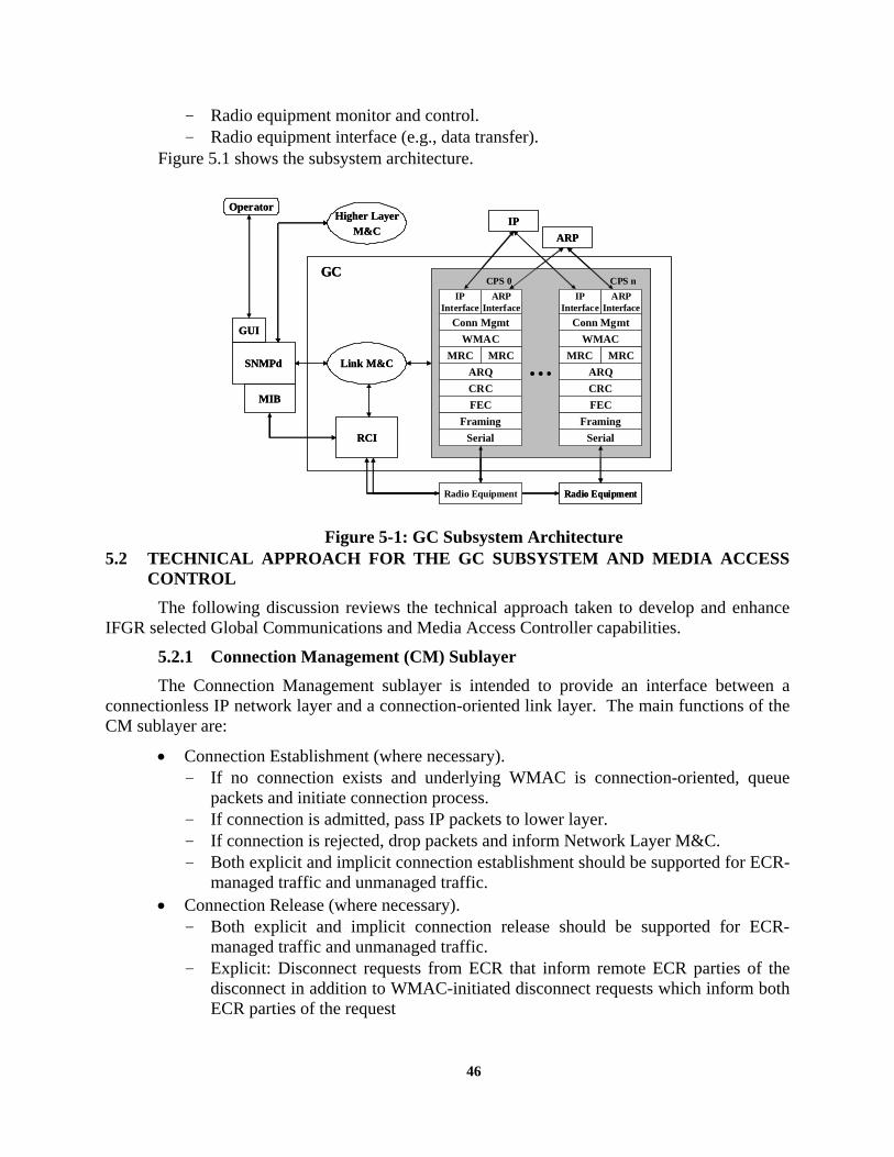
46
- Radio equipment monitor and control. - Radio equipment interface (e.g., data transfer).
Figure 5.1 shows the subsystem architecture.
Figure 5-1: GC Subsystem Architecture
5.2 TECHNICAL APPROACH FOR THE GC SUBSYSTEM AND MEDIA ACCESS CONTROL
The following discussion reviews the technical approach taken to develop and enhance IFGR selected Global Communications and Media Access Controller capabilities.
5.2.1 Connection Management (CM) Sublayer The Connection Management sublayer is intended to provide an interface between a
connectionless IP network layer and a connection-oriented link layer. The main functions of the CM sublayer are:
• Connection Establishment (where necessary). - If no connection exists and underlying WMAC is connection-oriented, queue
packets and initiate connection process. - If connection is admitted, pass IP packets to lower layer. - If connection is rejected, drop packets and inform Network Layer M&C. - Both explicit and implicit connection establishment should be supported for ECR-
managed traffic and unmanaged traffic. • Connection Release (where necessary).
- Both explicit and implicit connection release should be supported for ECR-managed traffic and unmanaged traffic.
- Explicit: Disconnect requests from ECR that inform remote ECR parties of the disconnect in addition to WMAC-initiated disconnect requests which inform both ECR parties of the request
Serial
FECCRCARQ
MRCWMAC
Conn Mgmt
MRC
FramingSerial
FECCRCARQ
MRCWMAC
Conn Mgmt
MRC
Framing
IP Interface
ARP Interface
CPS 0 CPS n
Radio Equipment Radio Equipment
Link M&CSNMPd
GC
Higher LayerM&C
OperatorIP
ARP
MIB
GUI
RCI
IP Interface
ARP Interface
Serial
FECCRCARQ
MRCWMAC
Conn Mgmt
MRC
FramingSerial
FECCRCARQ
MRCWMAC
Conn Mgmt
MRC
Framing
IP Interface
ARP Interface
CPS 0 CPS n
Radio Equipment Radio Equipment
Link M&CSNMPd
GC
Higher LayerM&C
OperatorIP
ARP
MIB
GUI
RCI
IP Interface
ARP Interface

47
- Implicit: UDP: Based on session timer TCP: Monitor TCP headers for FIN bit. Initiate disconnect process upon
detection of FIN sequence or upon expiration of session timer. • Link Admission Control. • Maintain separate queues for IP packets based on Link Service Access Point (LASP)
which provides a logical address between layer 3 and layer 2.
A software specification was developed for the CM layer that detailed primitives and APIs between the other software components of the IFGR system such as the Link Management and Control Agent (LM&C), the IP layer, ECR, and the WMAC. The detailed design is beyond the scope of this document; however, some aspects of the design are presented below.
Figure 5.2 shows the state transition diagram design of the CM. The transitions are primarily based on primitives established for communications among the other software components.
Figure 5-2: CM State Transition Diagram Table 5-1 lists the primitives and APIs developed in the CM software specification
corresponding to the transitions from states shown in Figure 5-2.
Init
ConnectSetup Idle
ConnectStatus
PacketTransfer
ConnectRelease
ReceivePacket
CmConnectReq WmDataInd
Default
No ConnectionExists
Session Timeout,Connect Timeout,CmDisconnectReq, orWmDisconnectInd
TCP FINSequence IITCP RST
ConnectionExists &&!LinkAnomaly
WmConnectInd,WmConnectCont,CmDataReq, IILinkClear
DefaultDefault

48
Table 5-1: CM Primitives INPUT PRIMITIVES Description CmDataRequest Determine whether connection exists. If so, transfer packet; if
not, set up connection WmDataIndication Pass to packet to IP layer. Check for FINs and ACKs WmConnectConf, WmConnectInd
Record connection information, transfer packet (future: refuse connection if necessary)
CmConnectReq Set up connection (or assume existing connection for unmanaged traffic)
CmDisconnectReq, TCP RST Begin connection release WmDisconnectInd Record connection status and inform ECR if managed traffic.
Pass payload to IP layer (if applicable). LinkStatus trap Set flag that is checked in Connection Status; if clear, transfer
any packets in queue for active connections OUTPUT PRIMITIVES Description WmConnectRequest Issued in Connection Status WmConnectResponse Issued in Connection Setup (future: may be used to refuse
incoming connection) WmDisconnectRequest Issued in Connection Release WmDataRequest Issued in Packet Transfer CmConnectConfirm Issued in Connection Status CmDisconnectInd Issued in Connection Release CmDataIndication Issued in Receive Packet
5.2.2 Wireless Media Access Control (WMAC) Sublayer Early research narrowed down the choice of feasible Wireless Media Access Control
(WMAC) protocols. Our investigation began with an assessment of the three basic multiple access techniques: frequency, code, and time division multiplexing.
While Frequency Division Multiplexing (FDM)-based access protocols are suitable for constant bit rate applications, they fail to take advantage of the benefits of statistical multiplexing to efficiently handle variable bit rate traffic. Because IFGR traffic characteristics vary widely, allocating a fixed-bandwidth channel to each aircraft could result in an unacceptable waste of limited channel resources. Furthermore, dividing the lower-bandwidth channels (such as the HF 2.4kbps channels) among multiple potential users would result in channel bandwidths that are too small to be practical.
Although spread spectrum techniques demonstrate high tolerance to channel interference and can provide high capacity due to low frequency reuse factors, Code Division Multiplexing (CDM) techniques require large bandwidths in order to utilize the spreading codes that provide access to multiple users. The required bandwidth is not available with narrowband, legacy HF radios. Even though more bandwidth is available to UHF radios, CDMA would not be able to efficiently use this bandwidth.

49
Time Division Multiplexing (TDM) protocols can be further categorized into time division duplex (TDD) and frequency division duplex (FDD)-based protocols. Although the time division duplex protocols require less hardware in the mobile terminals (MTs), they are advantageous where frequencies are scarce. Time division duplex protocols also incur additional delay in receiving feedback from the base station regarding time slot allocation or collision notification. Therefore, in a system that has two channels available for the uplink and downlink, FDD-based protocols can provide a timeliness advantage over TDD protocols. Timeliness advantages can be critical to delay-sensitive applications. However, since TDD systems can use the existing bandwidth more efficiently by varying the uplink and downlink subframe sizes with traffic demand, spectral efficiency must be weighed against timeliness in the selection of a MAC protocol.
Since efficient use of bandwidth is extremely important for the IFGR program, we determined that our investigation of MAC protocols focus on TDM/TDD protocols. TDM protocols can be classified as scheduled, contention-based, or reservation-based.
We investigated TDMA (scheduled); ALOHA, slotted ALOHA, and CSMA/CD (contention); and dynamic TDMA (reservation). We developed simulation models to help assess performance benefits of the various protocols. The initial model was used to compare the fundamental aspects of the proposed TDD D-TDMA scheme with a standard, synchronous TDD-TDMA scheme. The model was used to depict both estimated transfer times and percent channel utilization for a number of aircraft engaged in both transmitting and receiving files.
Like FDMA, TDMA performs well with constant bit rate traffic. However, strictly scheduled TDMA protocols are no better than FDMA with regard to statistical multiplexing benefits; bandwidth efficiency drops when the offered traffic varies. The MATLAB simulations showed that D-TDMA supported higher channel utilization as the demand varied when compared to a standard TDMA protocol.

50
Figure 5-3: Utilization of D-TDMA vs TDMA: Simulation Results Figure 5-3 shows the utilization of TDMA channel drops as demand fluctuates, while the
D-TDMA channel can remain at peak utilization. Also, when allocations were based on priority, transfer times of higher priority D-TDMA transmissions were significantly lower than in the TDMA model, as shown in Figure 5-4.
Figure 5-4: Transfer Times for D-TDMA vs TDMA: Simulation Results Both TDMA and D-TDMA protocols perform best with stream-type traffic. In addition,
D-TDMA works best with large file transfers. However, the cost of using D-TDMA is the
0 1 2 3 4 5 6 7 8
x 104
0
10
20
30
40
50
60
70
80
90
100D -TD M A M A CTDM A M AC
Traffic Transfer Time (sec)
Cha
nnel
Util
izatio
n (p
erce
nt)
0 1 2 3 4 5 6 7 8
x 104
0
10
20
30
40
50
60
70
80
90
100D -TD M A M A CTDM A M AC
Traffic Transfer Time (sec)
Cha
nnel
Util
izatio
n (p
erce
nt)
0 0.5 1 1.5 2 2.5 3 3.5
x 104
0
2
4
6
8
10x 10
5 Estimated Transfer Times for D-TDMA and TDMA
DL
File
size
(byt
es)
(D-TDMA) Priority =10(D-TDMA) Priority =5 (D-TDMA) Priority =3 (D-TDMA) Priority =2 (D-TDMA) Priority =1 (TDMA) Priority =10 (TDMA) Priority =5 (TDMA) Priority =3 (TDMA) Priority =2 (TDMA) Priority =1
(D-TDMA) Priority =10(D-TDMA) Priority =5 (D-TDMA) Priority =3 (D-TDMA) Priority =2 (D-TDMA) Priority =1
0 1 2 3 4 5 6 7
x 104
0
0.5
1
1.5
2x 10⁶
UL
File
size
(byt
es)
Time (sec)
(D-TDMA) Priority =10(D-TDMA) Priority =5 (D-TDMA) Priority =3 (D-TDMA) Priority =2 (D-TDMA) Priority =1 (TDMA) Priority =10 (TDMA) Priority =5 (TDMA) Priority =3 (TDMA) Priority =2 (TDMA) Priority =1 U
plin
k Fi
lesi
ze(b
ytes
)D
ownl
ink
File
size
(byt
es)

51
increased overhead required for bandwidth allocations in addition to the complexity of the scheme.
We then assessed contention-based protocols. Contention-based protocols perform well for short, bursty message traffic; however they are very inefficient to use with stream-type traffic. Excel simulations, shown in Figure 5-5, indicate that CSMA/CD performs best in terms of transfer time, followed by slotted ALOHA, and ALOHA.
Figure 5-5: Analysis of Contention-Based Protocols Based on analysis, a hybrid D-TDMA/S-ALOHA MAC protocol was recommended
which would capitalize on the advantages of both reservation and contention protocols to efficiently support IFGR’s diverse traffic types. It has been shown that contention-based protocols best support short, bursty messages with minimal delay (assuming the Base Station monitors utilization to ensure an adequate number of contention slots is maintained) and minimal overhead, while a dynamic reservation-based (D-TDMA) system best supports large file transfers and voice sessions. Although CSMA/CD performs best among the contention protocols, S-ALOHA is recommended to better integrate with a slotted framing structure.
Initial investigations of other MAC protocols were also performed in order to provide us with insight into existing frame and header structures that would be needed for a D-TDMA scheme. The 5-kHz UHF DAMA MIL-STD-188-182 and GSM standards were researched.
5.2.2.1 D-TDMA High Level Design
The overall approach of the proposed D-TDMA scheme utilizes TDM frames of a fixed length that can be broken into a number of sub-frames responsible for uplink (UL) data transfer (from the mobile terminals to the base station) and for downlink (DL) data transfer (from the base stations to the mobile terminals).
The DL sub-frames can be dynamically configured in order to provide both higher data rates, which are dependent upon a maximum number of users, for top priority users and lower data rates for lower priority users. When priority is irrelevant, these sub-frames can be
Average Transfer Time vs. Traffic Loadfor 40 Kbyte Data File
0
100
200
300
400
500
600
700
800
900
0 0.2 0.4 0.6 0.8 1 1.2
Traffic Intensity
Ave
rage
Tra
nsfe
r Tim
e (s
ec) Pure Aloha
Slotted Aloha
CSMA/CD

52
configured to provide service to all users depending on their specific needs. During low traffic periods, the sub-frames can be configured to transmit previously buffered data.
Similarly, the UL sub-frame can be dynamically configured depending upon the number of users and the priority level of the data transfers. In addition to the standard traffic data handled in the UL sub-frame, a slotted ALOHA (S-ALOHA) section is incorporated. The S-ALOHA mini-slots allow multiple users to be able to request access to the network. Figure 5-6 shows a sample frame and the corresponding sub-frames.
Figure 5-6: Proposed Framing Structure
The maximum data rates of the UL and DL sub-frames will be highly dependent upon the
burst data rate of the radios and the maximum number of simultaneous users. The maximum number of users along with the burst rate will determine the effective data rate. During inactive time slots, buffered data should be serviced in order to alleviate large accumulations of data.
To best support the requirements of IFGR, the D-TDMA protocol should support additional functions:
• Allocation of each slot will be determined mainly by priority and availability. Traffic monitoring will be required to determine whether any allocated slots are under-utilized. Under-utilized slots will be dynamically reallocated.
• Buffer management will be required to store and control the transmission of data. • Back-end users may be prompted to indicate the urgency of their transmission
request. Their decision on the urgency will be based on the knowledge of the current state of the network. The state of the network will provide the users with an approximate data transfer time under the current network conditions and an estimated transfer time during less busy periods. Network status information can be obtained from the NM processors and can be passed on to the user interfaces.
• Quality-of-Service (QoS) issues will most likely be addressed according to priority as determined by the IIM module. Higher priority data will demand higher throughputs and shorter service times. Lower priority data may not be guaranteed any specific data rate or service time. Connection Admission Control (CAC) may be an effective
Frame Header
Variable TDM Downlink
Movable Boundary
A B C
TDM Uplink(S-ALOHA)
A B C
Variable TDM Uplink
Request Access Mini-slots

53
technique that would furnish higher priority data access to the network, thus providing some level of QoS.
Based on these high-level D-TDMA WMAC design requirements, an OPNET simulation model was developed to assist in further refining details of the protocol. Both base station and mobile terminal models were developed. Although the simulation model did not fully incorporate the complexities of the higher layer IFGR software, it was able to confirm the basic operation of the protocol. This information with further analysis, as well as traffic profile data, could be used to determine the optimum frame size in follow-on work.
Figure 5-7: WMAC Base Station State Transition
5.2.2.2 D-TDMA Software Specification A detailed software specification was developed for the D-TDMA WMAC protocol.
Although state transitions were developed for the D-TDMA OPNET model, more detailed transitions were developed for the actual software specification. This section will provide an overview of those state diagrams. Additionally, frame and message formats were developed and will be briefly presented in this section. Finally, the software specification specified primitives and APIs between other software components of the IFGR system such as the CM, CPS MRC module, and the LM&C. Some aspects of the software specification are also presented in this section.
Figure 5-7 shows the state transition diagram provided in the WMAC software specification for the base station node. Detailed state and transition data can be examined in the WMAC software specification.
Figure 5-8 shows the state transition diagram provided in the WMAC software specification for the mobile terminal node. Detailed state and transition data can be examined in the WMAC software specification.
DeallocateSlotAllocation
PacketTransmit
SendHeader
PDU from Channel
Time Slot Req
MAC Address Request
Default
LQAAlloc
MACAddr
LQA Request
LQA Pending AND Channel free
Channel free
Default
Default
LQA Request
Idle
WMDisconnectReq OR Last PDUOR End LQA
PacketArrival
Packet from CM
Init
Frame timer
DeallocateSlotAllocation
PacketTransmit
SendHeader
PDU from Channel
Time Slot Req
MAC Address Request
Default
LQAAlloc
MACAddr
LQA Request
LQA Pending AND Channel free
Channel free
Default
Default
LQA Request
IdleIdle
WMDisconnectReq OR Last PDUOR End LQA
PacketArrival
Packet from CM
Init
Frame timer

54
Figure 5-8: WMAC Mobile Terminal State Transition
Table 5-2 illustrates the basic structure of a representative frame (shaded area indicates
frame time reserved for guard time, ramp-up, and synchronization bits appended at lower layers). Because time slots are allocated on a demand basis, the boundaries shown can change from frame to frame.
Table 5-2: Generic Frame Format
MiniSlot MT2 SlotBS SlotHeader MT1 SlotMiniSlot MT2 SlotBS SlotHeader MT1 Slot
The following outlines the structures of base station messages that were developed in the WMAC software specification. Figure 5-9 shows the format of the base station header.
Allocation End of
Allocations
24 8
Allocation
24
MT ID ConnID
StartTime
8 8 8
Allocation
24
BS ID ConnID
StartTime
8 8 8
BS Signaling
varies
End ofHeader
8
Allocation End ofAllocations
24 8
Allocation
24
MT ID ConnID
StartTime
8 8 8
Allocation
24
MT ID ConnID
StartTime
8 8 8
MT ID ConnID
StartTime
8 8 8
Allocation
24
BS ID ConnID
StartTime
8 8 8
BS ID ConnID
StartTime
8 8 8
BS Signaling
varies
End ofHeader
8
Figure 5-9: Base Station Header
MACAddr
ChanAccess
ReceiveAllocation
PacketArrival
Idle
Init WaitBS
Data Packet From Channel
WMConnectReq OR Request Reject from BS OR LQA Request trap OR collision occurs
Allocation From BS
MAC Address Assignment From BS
Initial frame From BS
Default
Default
PacketTransmit
Data Packet From CM OR EndLQA trap

55
A number of signaling messages are contained within the base station header. These messages allow the base station to allocate or reject resources to mobile terminals, assign MAC addresses to stations joining the network, an provide warnings to stations that are in violation of time slot use.
In addition to state transition diagrams, a set of software primitives were developed to communicate with other IFGR elements to support the functionality of the WMAC design. The full list of primitives and their details can be found in the WMAC software specification documentation. Table 5-3 provides a brief list of primitives along with their basic description.
The WMAC has been developed as a software specification. No formal software development has taken place.
5.2.3 Remote Control Interface (RCI) Subsystem The coordination and control of radio hardware is an important element in the design of
the IFGR system. The radios require a remote control interface so that other software processes can direct the radio resources when necessary. The remote control interface subsystem is responsible for communicating directly with radio hardware within the IFGR system. The RCI software component can operate independently. However, it is designed to work in conjunction with the Link Monitor and Control (LM&C) agent process. RCI can receive commands from the Link Monitor and Control (LM&C) Agent or from an SNMP Agent.
5.2.3.1 RCI Software Design The basic RCI software design strategy was to generalize the remote control interface so
that generic incoming commands could be translated into equipment specific commands. This design enables radios of similar types to have a common command interface.

56
Table 5-3: WMAC Primitives CM - WMAC Primitives Description WmConnectRequest Request a connection over the wireless link WmDisconnectRequest Inform the WMAC of the end of the ongoing message flow WmDataRequest Request over-the-air transport of data packets WMAC – CM Primitives Description WmConnectIndication Report connection establishment to the remote site WmConnectConfirm Report connection establishment results to the requesting site.WmDisconnectIndication Inform the CM that the remote terminal has completed
transmission and will deallocate the reserved slot after receiving acknowledgment of outstanding packets.
WmDataIndication Deliver incoming (over the air) data packets to the CM MRC – WMAC Primitives Description MrcDataRequest A command used to request over-the-air transport of data
packets. MrcDataIndication A status primitive used to deliver incoming (over the air) data
packets to the MAC. WMAC – LM&C Primitives Description FrameSize Frame size to be used (set by network manager). SerialOverhead Serial line overhead (e.g., guard time, tx rampup &
rampdown) to be used to prevent transmission overlap in adjacent time slots, etc.
CpsBlockSize Size of a CPS block (default 128 bytes). AvailableBW The amount of available bandwidth on the channel, conveyed
in terms of number of payload bytes that can be transmitted per frame.
ContentionSlot A MIB variable used to indicate the number of payload bytes that can be transmitted per frame.
LinkStatus An alert used indicate a change in link status. ModemRate The burst data rate of the modem, controlled via RCI. ChannelQuality An arbitrary assessment of channel quality based on factors
such as channel Signal to Noise Ratio (SNR), number of retransmissions, and number of error corrections.
LinkAllocRequest A command from the Link M&C Agent used to request the channel for LQA (for ALE radios) or for pilot voice communications, or to inform the WMAC that a handoff is pending (reject incoming connection requests).
LinkAllocStatus An integer code used to indicate one of four Link Allocation states, allocated for either LQA or pilot voice.
EndLinkAlloc A command used to release the channel after LQA/pilot voice is complete.

57
The basic functionality of the RCI software can be seen in Figure 5-10. After RCI starts, the main process waits for incoming commands from LM&C or SNMP inside the Send and Return function. Once a command is received, it is translated by the appropriate module and sent out the serial port to the equipment. The response to the command is returned through RCI and back to original invoking process, either LM&C or SNMP.
Figure 5-10: RCI Basic Functionality
5.2.3.2 Development of RCI The original RCI design and implementation was only capable of processing equipment
commands serially and servicing one piece of equipment at a time. RCI would execute by receiving parameters for a particular command, send this command to the equipment, receive data from the equipment, and then stop program execution.
One of the required upgrades for RCI was to record incoming equipment messages in real time. These messages are to be sent to the LM&C process for interpretation. In order for RCI to monitor all serial ports in real-time, the application was modified to remain open or active for an indefinite amount of time. However, in order to regain the ability to pass arguments to an already opened RCI application, FIFO (first-in, first-out) pipes (available in the Linux environment) were implemented. The FIFO pipes allow information to be passed uni-directionally from one open process to another. This allows commands to be sent to an already invoked RCI application and responses or unsolicited data to be sent to LM&C or SNMP.
In order to take advantage of information from unsolicited radio messages, as well as improve support for multiple serial ports in order to control multiple simultaneous links on a single IFGR Base Station, the serial port control modules within the RCI required restructuring.
RCI was modified to operate as a multi-threaded application to allow different portions of the code to run simultaneously during the execution of the application. In the RCI, each portion
LM&C
SNMP
Main
Send And Return
HF5022
HF5710A
UHF117
SerialComm
RCI Process
SerialComm
SerialComm
Translation Functions
RF5022Radio
RF710AModem
UHF117Radio
Equipment
Command
EquipmentCommand
EquipmentResponse
Equipment
Response
Wait
for i
ncom
ing
comm
ands
Equipment

58
(or thread) of code is responsible for the real-time monitoring of the available serial ports on the PC-104. RCI can spawn an individual thread to monitor each available serial port.
5.2.3.3 RCI Supported Equipment Commands The RCI modules supported under the IFGR contract were the Harris RF5022 HF Radio,
the Harris RF5710 HF Modem, the Harris RF5710A HF Modem and limited support of the Harris AN/PRC-117F.
A highlight of the command set for each piece of equipment is listed in Table 5-4. Not every possible command was implemented for each piece of equipment. Only those necessary to support the concept of operations for the IFGR program were implemented.
Table 5-4: RCI Command Set
RF5022 – HF Radio HF5710(A) – HF Modem PRC117F – UHF Radio Command Description Command Description Command Description ALE Place radio in
Automatic Link Establishment Mode
ASYNC * Commands to configure the asynchronous port of the modem (i.e. bit rate, stop bits, etc)
DAMA Set radio into DAMA operation mode
SHOW Display Radio status
DATA RATE
Set the transmit and receive data rate of the modem
NORMAL Set radio into normal operation mode
SSB Place radio into single sideband mode
MODEM * Commands to configure modem settings (i.e. interleave, duplex, keyline)
PRG Set radio into program mode
DATA * Set the data port settings of the radio (i.e. baud, bits per character, etc)
TERMINATE
End a DAMA call
REMOTE *
Set the remote control port settings of the radio (i.e. baud, bits per character, etc)
PORT REMOTE *
Set the remote control port settings of the radio (i.e. baud, bits per character, etc)
ZERO Clears all radio settings
PORT DATA *
Set the data port settings of the radio (i.e. baud, bits per character, etc)
SSB * Configure parameters for SSB channels (i.e. frequency, bandwidth, etc)
DAMANET *
Set damanet commands (i.e. netname, channel, etc)
ALE * Execute ALE based commands (i.e., CALL, LQA, RANK)
NET * Set net commands (i.e. name, power, frequency, etc)

59
5.2.3.4 RCI GUI Development As part of the RCI software package, a GUI written in Java was developed to invoke RCI
commands via SNMP. The RCI GUI was developed only as a supporting tool to the GC subsystem. The GUI was developed so that a user could access RCI commands in addition to configuring the operation of the LM&C code. This section will focus only on the RCI aspects of the GUI.
The GUI allows a user to manually control radio equipment if necessary. Since SNMP was the underlying protocol for invoking equipment commands, the GUI could access RCI on a machine local to the GUI, or the GUI could access RCI remotely if both machines had network connectivity.
Although in the cases of the HF radio and modem, the GUI supports a large set of commands for that equipment, not all of the underlying software (RCI and SNMP) was developed to support all of the commands issued by the GUI for the PRC117.
Figures 5-11, 5-12, and 5-13 show portions of the RCI GUI for the RF5710A modem, RF5022 radio and PRC117F radio, respectively.
Figure 5-11: RCI GUI - RF5710A

60
Figure 5-12: RCI GUI - RF5022 (SSB Mode)
Figure 5-13: RCI GUI – PRC117 (Standard Mode)

61
Version 2.0 of RCI was delivered for integration into the IFGR system. This version was developed in C++ on a Linux Red Hat 7.3 platform using kernel version 2.4.18.
5.2.4 Link Monitor and Control Agent (LM&C) Subsystem The Link Monitor and Control Agent (LM&C) was developed to maintain, monitor, and
control link communications across a variety of radio and modem equipment. The LM&C is responsible for the overall decision making process used to maintain wireless communication links or to perform link functions as instructed by other software components such as the WMAC. LM&C employs the use of RCI to issue and receive radio commands and responses. Some examples of the processes that LM&C performs are:
• Establishing a call or link between radios • Terminating a link • Using built-in radio functions to estimate link quality • Gathering information to make decisions on how to maintain a link The LM&C is also responsible for communicating with other software layers to convey
link information. LM&C makes available to ECR the approximate bandwidth that can be achieved over any of the available IFGR radio interfaces. The approximate bandwidth is based off a fractional estimate of the data rate of the modem connected to each interface. This information is provided to ECR via a shared memory interface.
LM&C also contains an SNMP interface that can be used to query link status for any of the links under control.
5.2.4.1 LMC Software Design LM&C was developed to support two types of links: • HF Links using RF5022/RF5710A • UHF Links using PRC117F in DAMA mode The basic design of LMC is shown in the state diagram in Figure 5.14. Although the
Figure shows the specific design of the HF link monitoring process, the designs of other link processes are similar in their organization and operation.
LM&C was designed for two states of initialization, automated or operator controlled. In automated mode, the LM&C will begin operation if no manager or user intervention is established within a set timeout period. If a manager is present, LM&C will wait for a manager to issue the command to begin operation.
Once the LM&C begins operation it loads all available equipment parameters. After the parameters are loaded, LM&C will enter operation as a mobile terminal (MT) or base station (BS).
If a station is operating as a MT, it is responsible for contacting the BS by performing typical radio rank and call functions to determine the best possible base station to contact. Once the MT becomes linked, as determined by the radio hardware, it will notify the upper layer ECR software of a new connection. The LM&C will then enter the Idle state where it will periodically check the link status by querying both the radio and CPS data. LM&C will continue this periodic check until it is time to perform a Link Quality Analysis (LQA) on the channel or if the link is

62
disrupted or broken. After performing LQAs, the MT will attempt to recall a BS and repeat the cycle. Future states allow for rate adaptation based on the performance of a link.
If a station is operating as a BS, it is responsible for performing periodic LQAs while waiting to be contacted by a MT. Once a BS is contacted by a MT and a link is established, the BS will notify ECR that a link is available. Similar to the MT, the BS will periodically check link status. If the BS determines a link is not sustainable, it may break contact with the MT. The MT will be responsible for attempting to re-call the BS.
Figure 5-14: LM&C State Transition Diagram (HF Link)
When LM&C operates in UHF DAMA mode, additional inputs factor into the call
making process. The location of the BS and the coverage of the DAMA satellite footprints need to be considered when making a call. This is especially important in handoff scenarios when a MT might move into different footprints. Figure 5-15 shows two overlapping footprints as an example.
For each “latitude bin,” three longitude thresholds will be stored, indicating the urgency of the handoff. A handoff protocol based on urgency is recommended to minimize communication disruption. While in the “green” region, the aircraft can afford to wait for a convenient time (i.e., when the channel is not in use) to perform the handoff. In the yellow region, however, the aircraft issues a request to clear the channel. In this case, no new connections will be admitted, but the LM&C agent will still wait until the link becomes available, or until the aircraft passes into the “red” region, at which time the handoff must be performed regardless of risk of lost data.
Init AutoInit
LoadEquipConfig
DataInterrupt
StopM&C
OpenChannelLQA
Automatedtimeout
Link configurationDiagnostics fail ANDOperator initialized
OperatorInitIACC GC Control
Initialization Process
StartSelectedLM&Cthread
DefaultOperatoroverride
Idle Rate/ErrorAdaptation
Linked
Soft DataInterrupt
CheckLink
Status
LateOperator
per link
BS
BS AND !retune MT ORretune
CPS queue emptyOR timeout
LQA periodOR LinkInterruptrequest
Default
Default
DefaultLink fail
Link quality poor
Data rate anomalyOR low SNRError rate threshold
Polling period
OK
LinkInterrupt trapOR Scanning trap
Linktrap
Linked
Restart ANDMT ANDNOT Linked
Restart AND(BS ORLinked)
Stop M&CCommand
OperatorOverride
MT

63
Figure 5-15: LM&C UHF Handoff
5.2.4.2 LM&C Development and Management Process Similar to RCI, a Java GUI was developed to provide a front end management operation
of LM&C. The management GUI of LM&C allows a user to configure the link operation of LM&C. The GUI was developed as a supporting tool to LM&C. It is not required to operate LM&C.
The basic design of the Manager process is shown in Figure 5.16. The Manager process attempts to override LM&C before it begins or attempts to override LM&C after it has already begun. Once LM&C is overridden, the GUI was designed to be able to reconfigure the mode of operation of the links. The GUI was also designed to store and update operational thresholds for the links such as SNR ratios for the HF links, and satellite footprint information for UHF DAMA links.
The following Figures show the Manager GUI developed to interface with LM&C. The GUI uses SNMP to issue commands to LM&C. Figure 5-17 shows the initial GUI screen for configuring the links. The screen allows a user to configure links with equipment connected to a particular port. Once the link is configured with equipment, the user can launch the start screen.
Figure 5-18 shows the GUI start screen for a single link. This portion of the GUI allows a user to configure link operation parameters and thresholds. Although many of threshold parameters are not fully implemented in underlying LM&C code, this serves as a place holder for future upgrades. Figure 5-19 shows an example threshold screen for an HF link.
Figure 5-20 shows the GUI that is used for monitoring the link operation. It indicates the relative link condition and additional parameters of interest to the link.
Footprint for Satellite1 Footprint for Satellite2
SoftTransfer
UrgentTransfer
HardTransfer
NoTransfer
Latitude bin
Threshold longitude for {latitude bin, transfer area}
Similar threshold concept for LOS:For each BS, store set of soft, hard, and urgent thresholds for distance and altitudeCompare current distance and altitude to thresholds to determine transfer “area”
SoftTransfer
UrgentTransfer
HardTransfer
NoTransfer
SoftTransfer
UrgentTransfer
HardTransfer
NoTransfer
Latitude bin
Threshold longitude for {latitude bin, transfer area} Latitude bin
Threshold longitude for {latitude bin, transfer area}
Similar threshold concept for LOS:For each BS, store set of soft, hard, and urgent thresholds for distance and altitudeCompare current distance and altitude to thresholds to determine transfer “area”

64
Figure 5-16: LM&C Manager Process
Figure 5-17: LM&C Manager GUI
Init ConfigureLink
ConfigureEquip
StoreLink
Config
SpecifyThresholds
RunLM&C
StartLM&C
Operator override ACK1
Default
Stop ORInvalid password Configure
Stop ORIncorrect
Link config
Operator override ACK2
Resume
Start
LM&C
Incomplete linkconfiguration
Store
Threshold
Default
1 layer of windows per link;Within a layer, windows are modal
Init ConfigureLink
ConfigureEquip
StoreLink
Config
SpecifyThresholds
RunLM&C
StartLM&C
Operator override ACK1
Default
Stop ORInvalid password Configure
Stop ORIncorrect
Link config
Operator override ACK2
Resume
Start
LM&C
Incomplete linkconfiguration
Store
Threshold
Default
Init ConfigureLink
ConfigureEquip
StoreLink
Config
SpecifyThresholds
RunLM&C
StartLM&C
Operator override ACK1
Default
Stop ORInvalid password Configure
Stop ORIncorrect
Link config
Operator override ACK2
Resume
Start
LM&C
Incomplete linkconfiguration
Store
Threshold
Default
1 layer of windows per link;Within a layer, windows are modal

65
Figure 5-18: LM&C Start Link GUI
Figure 5-19: LM&C Manager Process

66
Figure 5-20: LM&C Monitor GUI
Version 2.0 of LM&C was delivered for integration into the IFGR system. This version
was developed in C++ on a Linux Red Hat 7.3 platform using kernel version 2.4.18.
Included with the LM&C software, the Manager GUI software was delivered but not integrated with the IFGR system. System testing and evaluation is required to bring the Manager software to a baseline operational state.
As RCI and LM&C software develops, the MIBs supporting these processes are extended when possible.

67
6.0 INFORMATION ASSURANCE
In order to meet the need of secure timely communication for the warrior we set out to create the Information Assurance architecture for the transmission of secure authenticated information (messages) over the existing IFGR network. The intent is to:
• Advance the state-of-the-art in secure mobile communications by integrating key Information Assurance technologies with IFGR.
• Support the incorporation of IFGR technologies in highly mobile, multi-level, and multi-national operating environments.
• Develop an IAA that can be integrated with IFGR to provide authentication, data integrity, data privacy, non-repudiation, Intrusion Tolerance, support Dynamic Coalitions and provide mult-level based discretionary access control.
• Eliminate the need for certified workstations by devising a method to provide secure messaging and advanced Information Assurance services based on the keying material that is possessed by each individual in tamper-proof personal cryptographic processing modules, along with appropriate mission based secure applications.
6.1 GOALS AND SECURITY OBJECTIVES FOR INFORMATION ASSURANCE In order to achieve the necessary security requirements and provide an effective trusted
solution to the user the Information Assurance Architecture must be:
• Standards based (PKI, FIPS, IETF) • Multi-level / Multi-national • Able to be validated / certified • Able to be integrated into the IFGR architecture • Writer to Reader secure • Based on strong cryptographic methods supporting the information assurance tenants:
- Authentication - Data Integrity - Access Control - Data Privacy - Auditing - Non-Repudiation - Multi-Level Security - Intrusion Tolerant - Mission Specific - Dynamic Coalition
Several security definitions will be used in the discussion of Information Assurance that
follows:
• Encryption Algorithms: - Asymmetric - Uses one key to encrypt data and a different key to decrypt the
same data. Also called public-key/private-key cryptography. - Symmetric - Uses a single key to both encrypt and decrypt data. - Type I (can be Symmetric or Asymmetric) - Classified or controlled
cryptographic algorithm endorsed by the National Security Agency for securing classified and sensitive U.S. Government information.

68
• Encryption Strength: The strength of encryption is based on the algorithm used and the key size. Using multiple stages of encryption can increase this strength.
Our goal was to provide for the selection of multiple algorithms per message based on the recipients and threat level. The advantages of token-based encryption are that the private keys are NEVER exposed and that all cryptographic operations are processed inside the secure cryptographic hardware boundary.
The Concept of Operations for Information Assurance is shown in Figure 6.1 below.
Figure 6-1: Information Assurance Concept of Operations
The Writer-to-Reader security model employed on this Concept of Operations has
multiple benefits because it places the security closer to the user. The security burden is removed from the transport layer and can allow for any transport to be utilized. This model does not require link encryption and physical protection, however it can utilize it if it is available; there is also a minimized risk of compromise by protecting messages from writer to reader.
6.2 TECHNICAL APPROACH FOR THE IFGR INFORMATION ASSURANCE ARCHITECTURE (IAA)
The IAA for IFGR messaging is comprised of the following components:
• IFGR Secure Mission Manager. The Mission Manager acts as a Certificate Authority (CA) for a Mission by authorizing users and user attributes. The Mission Manager issues FIPS-140-2 cryptographic modules based on mission policy and manages the public key infrastructure during the Mission.
• Multi-force, multi-national e-mail
• Role-based access control, security levels & enclaves
• Mission planners define roles & communities
• Enforced by key distribution, cryptography
• Scaleable integrity, encryption & authentication
• Originators are unable to create or send “bogus” messages
• Recipients are unable to read messages outside their authority
Secure Message ObjectSecure Message Object
IFGR Messenger
Writer
IFGR Messenger
Reader
IFGR Infrastructure IFGR InfrastructureIFGRSecure
Messaging
IFGR Multi-media Transport
• Multi-force, multi-national e-mail
• Role-based access control, security levels & enclaves
• Mission planners define roles & communities
• Enforced by key distribution, cryptography
• Scaleable integrity, encryption & authentication
• Originators are unable to create or send “bogus” messages
• Recipients are unable to read messages outside their authority
Secure Message ObjectSecure Message ObjectSecure Message ObjectSecure Message Object
IFGR Messenger
Writer
IFGR Messenger
Writer
IFGR Messenger
Reader
IFGR InfrastructureIFGR Infrastructure IFGR InfrastructureIFGR InfrastructureIFGRSecure
Messaging
IFGR Multi-media TransportIFGR Multi-media Transport

69
• IFGR Secure Messenger. The Messenger is a secure application providing e-mail composition, transmission and retrieval, it also provides access to and uses advanced IA technologies to protect and verify information.
• Cryptographic Tokens. User tokens carried by mission personnel are used to access the security services.
• BIOAPI Compliant Biometric Device. A biometric reader is the standardized method for collection and verification of biometric identity.
• Sovereign Time Trusted Time Stamp Servers. The time stamp server provides a standardized, traceable, non-reputable source of time.
The IFGR system provides the transport for Writer-to-Reader communication model.
6.2.1 IFGR Secure Mission Manager The IFGR Mission Manager is a secure communication management application, which
interacts with cryptographic tokens, biometric devices and the IFGR knowledge base to create and manage missions, tokens and users. The Mission Manager is used to setup and define all the parameters and users for a Mission, create Mission and User tokens, store biometric identification and allow for database management.
The IFGR Mission Manager:
• Allows creation of mission • Generates mission cryptographic keying material • Creation and management of Mission Users:
- Define User Specific Roles from the Mission Roles - Issue cryptographic tokens to users - Collect biometric identity information from each user
• Provides cryptographic keying material exchange to Mission User • Define Mission Roles • “Roll your own categories“ • Create arbitrary number of roles based on need • Role names dependent on the mission • Selection of encryption level dependent on mission requirements • Selection of type of signatureWorks in conjunction with the IFGR knowledgebase
Designed to be one component in an integrated messaging system, the IFGR Secure Mission Manager enables an operator to customize the messaging abilities of individuals participating in a specific mission. The role-based IFGR messaging system depends on a set of roles defined within the Mission Manager and used by each user of the system.
With the Messenger application, an IFGR user can send secure messages to other IFGR users. Messages are protected and authenticated using PKCS #11 hardware encryption devices.

70
Figure 6-2: IFGR Mission Management Screen
The Mission Management interface, shown in Figure 6.2, displays the information for the mission selected in the Mission Name drop down box. The mission name, ID, code, start and end times, indication of mission status (active/inactive) and whether or not a mission token has been issued are displayed. The available role-based security settings for the mission are also displayed.
The New Mission interface, shown in Figure 6.3, allows for the creation of a mission and entering or selecting the necessary specifications. If a mission token is to be created, cryptography and signing options are also selected. This interface provides the ability to customize the creation of categories for clearances, organizations and roles.
The user management interface, shown in Figure 6.4, displays all users in the user table of the IFGR knowledgebase, along with partial information for the mission if the user is associated with a mission. This interface allows for the creation and deletion of users and the ability to set or change a user’s password. If the user is associated with a mission that has a token then the user token can be created with roles that are available for that mission. If a biometric device is available both a biometric identity and biometric duress can be entered and stored on the token.

71
Figure 6-3: IFGR New Mission Screen
Figure 6-4: IFGR User Management Screen

72
6.2.2 IFGR Secure Messenger The IFGR Secure Messenger is an enhanced email client application designed work with
the tokens created for a Mission to provide the user with a customizable tool to secure their communication before sending from their workstation and receive securely transmitted messages from other Mission participants. The IFGR Secure Messenger:
• Requires tri-modal authentication to access application • Allows generation of protected messages • Automatically encrypts and signs message content • Provides selectable message, attachment and image protection mechanisms • Allows display and reading of messages based on issued security settings.
Designed to be one component in an integrated messaging system, the IFGR Secure Messenger lets a user send and receive secure email messages to other IFGR users based on specific roles. The available roles and the assignment of those roles are held within the user’s PKCS #11 token. The messages are protected and authenticated using PKCS #11 hardware encryption devices.
Figure 6-5: Standard Logon
The standard login for the user is shown in Figure 6.5. The Messenger searches all USB
ports, locating the ones that have a token inserted. The Name field presents a drop-down menu that lists all the tokens found. The label on each token is displayed along with the USB slot number in which it is located. The slot number indicates the USB port number but can change as tokens are inserted or removed.
Figure 6-6: Tri-Mode Authentication Logon

73
If a biometric device is available a Tri-Mode Authentication Login procedure requires a password, a token and a biometric, as shown in Figure 6.6. This added level of security is maintained by a process which verifies, through comparison, the user’s fingerprint template stored in the token to the actual user’s fingerprint being read by the Precise Biometric 100A. If verified successfully the user is then allowed to log into the IFGR Messenger application by clicking on the “OK” button.
Figure 6-7: IFGR Secure Email Client Application
Figure 6.7 shows a typical email client interface with added information assurance features. A digital signature can be added to the email using a certificate from the token. The message can be encrypted with a choice of algorithms. A timestamp and biometric can be added to the message for verification. A valid starting and expiration time can enforce the point in time of the message. Specified security settings for the message are available based upon the user’s roles.
This client includes an inbox, a sent message box, a new message window and the necessary configuration options to customize the application for each user. Each user’s configuration is stored in a local database.
6.3 ENHANCEMENTS TO CURRENT IFGR MESSAGING FUNCTIONALITY The IFGR Secure Messenger provides many distinct security features above those of a
standard email client application. The utilization of cryptographic tokens, biometrics, secure time

74
stamp servers, security levels and message and image verification are the means to enhance this functionality.
6.3.1 Token Issuance Personal cryptographic modules (tokens) are issued to all participants of a mission.
Mission parameters, user’s roles/rights, biometric identity and cryptographic keys are all contained within the module. A token with the appropriate security settings is required for the user to be able to access security services on a Mission. Since the user tokens were all created using the Mission key a separate cryptographic key exchange is not needed
6.3.2 Authentication If a biometric device is available then the tri-mode authentication process is required to
access the Mission Messenger. Each received message is authenticated based on the mission and selected encryption keys.
6.3.3 Access Control Access to the Messaging application requires tri-mode authentication (token, password
and biometric). The ability to view messages is cryptographically controlled by the role(s) assigned to the user.
6.3.4 Cryptographic Message Protection All transmitted messages are encrypted. Policy-controlled requirements dictate the
minimum level of cryptography used. Both symmetric and asymmetric encryptions are used.
6.3.5 Time Controlled Messaging “Do not open until” and “Do not open after” constrained messages are enforced by
Trusted Time. Each transmitted message is time stamped. Time stamps can be viewed and independently verified.
6.3.6 Biometric Identity Integration If a biometric device is available then biometric confirmation is required for application
access. Policy-based use of biometrics is implemented to control message release and message viewing. Biometric transmission and verification is transparent to the receiver. Biometric read receipts ensure that a particular user was present when the message was read. The ability to covertly transmit a duress message based on a selected biometric has also been implemented.
6.3.7 Message Processing of Different Clearance Levels Clearance levels are user defined. Each message requires a clearance level to be selected
before transmission. All messages are encrypted at a minimum according to two factors: Mission and Clearance. Only users participating on the Mission AND possessing the proper Clearance can access the message. The system can process both Unclassified and Sensitive messages.
6.3.8 Cryptographic Revocation The Cryptographic keys can be remotely revoked in the field. The revocation process
does not require a CRL.

75
6.3.9 Message Integrity Messages are encrypted with DES. RSA signatures are automatically applied to the
messages. The ability to sign individual message components (message text, attachments) is also provided. The selection of multiple additional hashes (SHA-1, MD5) can be applied to the message. There is also the ability to apply additional levels of encryption to messages (SKIPJACK).
6.3.10 Image Integrity Watermarking, self-embedding steganography, hierarchical image protection, and
customized compression algorithms for the transmission of approach plates are provided for additional protection of image integrity.
6.3.11 Robustness The Messenger uses standard SMTP and POP services (no extensions). The message
compression, encryption and signing has been automated. These protection mechanisms add very little overhead to message (independent of message size). The protection mechanisms are configurable based on mission requirements or policy.
6.3.12 NSA Certification Process We met with the National Security Agency (NSA) on October 15, 2003 and gave the
IFGR Capabilities Presentation to NSA personnel. Our presentation provided an opportunity for us to brief NSA on the security solution we have designed and developed for the IFGR project and to get feedback on our approach. This meeting was not a requirement for certification and was designed to communicate the concepts and ideas behind our secure communications systems in IFGR and to obtain input from NSA regarding our technological approach and certification plans.
6.3.13 Continued Integration Of Information Assurance Components Currently the IFGR Mission Manager and Messenger exist as stand alone applications.
We are currently implementing a more seamless integration into the browser interface that exists for IFGR. This will begin with the execution of these applications from a link or button on the existing IFGR web interface. An assured login from the web interface is also being developed.
6.4 FUTURE TECHNOLOGIES AND CAPABILITIES PROPOSED FOR INFORMATION ASSURANCE
The following technologies will be pursued in the next phase of the IFGR program.
6.4.1 IFGR Toolbox
The creation of a set of Information Assurance Services and utility functions will be created and be available for use by every IFGR component running on an IFGR node. Two such features include the ability to perform a true authenticated login with the exchange of challenges to an IFGR authentication service over a secure channel, and the ability to perform remote biometric authentication. A cryptographic processor will be directly integrated into an IFGR node in either a PCI board or PCMCIA card type device. The API will communicate with a set of Information Assurance Services running on the node. A simple set of function calls will be

76
made available to access the various services, including encryption, time stamping and GPS location.
The toolbox will contain the following features: • A user will be able to login with the use of a token and a biometric device • Provide the authentication of the identity of the user against a server database (i.e.,
IFGRKB) • Onboard GPS receiver will provide location information to indicate where the node is
located • A secure Time Stamp Server will provide the verification of when an event occurred • APIs will provide simple but secure methods to obtain/transmit data • Processes will directly integrate with the IFGRKB for tracking of activity and provide
an audit record of system usage • Individual processes would not need to directly communicate with hardware devices
(Time Stamp Server, Cryptographic device, GPS receiver, etc.)
We are researching a method to use the current radios to transmit value-added alert information on top of standard voice communication, shown in Figure 6.9, over the existing channels without adding any message overhead or altering the intended use of the radio. Using well-known steganographic techniques, messages can be embedded (hidden) in the transmitted vocal waveforms, as shown in Figure 6.9. A message can consist of any type of digital information ranging from a simple text message to a True Color JPEG image. We will build a proof of concept prototype system to be used to test the ability to perform the automatic ability to injected and extract digital information over UHF radio communications.
Figure 6.8 illustrates the services to be provided:
Figure 6-8: Information Hiding Using Steganographic Methods
IFGR Assurance Services *Authentication
• Token • Biometric
*Secure Connection *Provide Audit Record
IFGRKBPostgreSQLDatabase
Use crypto- token & session
Store User Credentials
Location Tracking
Time Verification
Client Assurance
GUI
Biometric Device
Cryptographic Token
GPS Receiver
Client API
Server API

77
When standard UHF or VHF radio communication occur , analog voice data is converted
to a digital format via an Analog to Digital Converter (A to D Converter). The digital information is transmitted, received by the other side, then is converted back into an analog representation to be heard by the recipient.
Figure 6-9: Standard Voice Communication Our proposed approach allows the injection of a digital message (text, image, sound, etc.)
as part of the conversion process. As streaming audio is converted to a digital format, each digitized audio sample is modified using a single bit of data from the injected digital message. Essentially, the bit stream representing the digital message is ‘added’ to the resulting digitized audio. The new waveform is then transmitted and received as in the standard communication, where a steganographic decoder pulls the superimposed digital message stream off the audio message. The digital audio stream is then converted back to an analog signal and can be heard. The Information Decoder can totally remove the embedded information before the digital to analog conversion (as is illustrated) or the embedded information can remain in the signal. Either way the resulting analog audio will sound the same. This special feature allows systems with the special Information Decoder to receive the embedded messages, but others without it – simply do not know that the embedded information exists.
Figure 6-10: Voice Communication with Embedded Alert
The NSA capabilities presentation that was presented last year is being updated based on the results of the previous meeting. We have continued to work with NSA to discuss issues that where of concern or that required clarification. Additional meetings need to be held with NSA to update them on our current status and to represent and updated capabilities presentation.

78
6.4.2 DITSCAP It is anticipated that a more formal DITSCAP process may be needed for the certification
of IFGR as a whole. We continue to pursue the DITSCAP process and will work with a Security Approval Authority (SAA) to produce DITSCAP required documentation, including the System Security Authorization Agreement (SSAA).