influence of stones’ size on the collapse of masonry bridges8gracm.mie.uth.gr/papers/session...
TRANSCRIPT

8th GRACM International Congress on Computational Mechanics Volos, 12 July – 15 July 2015
INFLUENCE OF STONES’ SIZE ON THE COLLAPSE OF MASONRY BRIDGES
Borja Conde1, Georgios A. Drosopoulos
3, Belen Riveiro
1, Maria E. Stavroulaki
2
and Georgios E. Stavroulakis3
1
School of Industrial Engineering, Department of Engineering Materials, Applied Mechanics and Construction, University of Vigo
Vigo, ES-36310, Spain e-mail: [email protected]; [email protected]; web page: http://geotech.webs.uvigo.es/
1School of Architecture, Technical University of Crete
Chania, GR-73100, Greece e-mail: [email protected]; web page: http://www.arch.tuc.gr
1
School of Production Engineering and Management, Technical University of Crete Chania, GR-73100, Greece
e-mail: [email protected]; [email protected]; web page: http://www.comeco.tuc.gr
Keywords: Masonry bridges, collapse analysis, limit load, geomatic techniques, contact analysis.
Abstract. Masonry bridges have been measured with geomatic techniques, including terrestial photogrammetry and terrestrial laser scanning. The collapse mechanism and load has been calculated by using finite element analysis with unilateral contact and limit analysis estimation. From parametric analysis we can prove that the minimum size of the stone near to a hinge in the arising collapse mechanism has a decisive effect on the collapse load. Nevertheless, reinforcing this weak point, could lead to a different collapse mechanism. 1 INTRODUCTION
Many of masonry arch bridges still survive, therefore a detailed analysis of these monuments, is of great interest. Masonry arches consist of stone blocks and the mortar joints. In the past a number of theories have been developed in order to represent the mechanical behavior of this composite material which consists of stones and mortar in between, with high compression and low tension strength. Several ancient constructions built with mortar joints have experienced a significant loss of mortar due to environmental erosion and have become mechanically similar to constructions originally built with dry joints.
The study of the masonry arch has a long tradition in the engineering literature, since the investigation of this structural system with long expected life subjected to a number of earthquakes is of great interest [1], [2], [3]. Several computational methods have been developed for modeling and analysis of historical masonry structures [5] and are used, for example, for the evaluation of the limit load of a masonry arch. The theory of continuum damage has been used for the modeling of the mechanical behavior of masonry structures and the calculation of damage indices [4], [5]. On the other hand cracks may appear due to the no-tension property of masonry. Furthermore, energy dissipation mechanism arising along contact interfaces is certainly responsible for the beneficial aseismic behavior of these structures. The discrete element methods could be used, but a complete analysis of a stone masonry with thousands of particles and interfaces would not be efficient for the structural engineer. Therefore the use of some phenomenological or potential interfaces along the lines where cracks and other damage are possible to appear is a promising alternative [6], as it was given under the study of several damage scenario of the Plaka stone bridge in Epirus, Greece by using unilateral contact models along interfaces, [7], [8] and the comparison with a model using the theory of continuum damage mechanics, under static loads [1]. Modeling of different masonry arch bridges under static loads is presented in [9] using finite element analysis and considering crack planes perpendicular the arch ring. These interfaces were modeled by point contact elements and shear panel elements. So theoretical developments in the area of nonsmooth and contact mechanics, and the availability of powerful computers allow us to perform finite element computations including unilateral contact and friction effects.
Considering that a structure has suffered from a destructive loading in the past, small or larger deformations and damages or cracks has remained after this experience. Using terrestrial photogrammetry or laser scanning
Borja Conde, Georgios A. Drosopoulos , Belen Riveiro, Maria E. Stavroulaki and Georgios E. Stavroulakis
technique we can accurately measure the current state of the structure and the exact representation of the geometry of the structure could be achieved. The information of the surface measurements can be extended by either additional measurements or focused post processing of data in order to find surface defects or cracks or by adding information from the interior of the structure, by using for example geophysical prospection or other suitable techniques.
In this paper two masonry arch bridges were considered as cases studies, Cernadela Bridge and Xuño Bridge both of them in Galicia, north of Spain. Non-linear finite element analysis models with principles taken from continuum damage mechanics, contact mechanics and collapse analysis are used for the evaluation of the ultimate load and collapse mechanism, in a macroscopic level. Additionally in order to investigate the influence of the real geometry and special the stones size of the arch to the collapse mechanism, various two-dimensional slices taken along the arch of Xuño Bridge were analyzed.
2 GEOMATIC TECHNIQUES FOR HIGH PRECISIÓN GEOMETRY RECONSTRUCTION
2.1 Terrestrial Photogrammetry, Terrestrial Laser Scanning and Ground Penetrating Radar
New geomatic techniques allow us measure structures of complex shapes and create accurate models for further structural analysis. Photogrammetry is defined as a method that allows the geometry of objects to be reconstructed from images, where the object has previously impressed. This is possible through the establishment of geometrical relationships between objects coordinates (in 3D space) and image coordinates (in 2D space) into a perspective system. This is usually performed through the collinearity condition that establishes that, at the time of exposure, a point in the object space, the perspective centre and the image coordinates of the point all lie in common straight line. This condition is drawn through the collinearity condition equations that are widely explained in [10]. As a summary of this, we can assume that is possible to obtain the 3D coordinates of the position of any point of object space by knowing the image coordinates of it.
Terrestrial Laser Scanning is another geomatic method that enables the geometry of the surface of objects to be automatically reconstructed by using LiDAR technology (Light Detection and Ranging). This principle of operation compute distances trough the measurement of the time needed by the laser beam to reach the object’s surface and return back.
Laser beam is directed in two planes, the vertical and horizontal one providing two angles for each point of the actual position of the object being scanned together with the measurement range. By recording this two values, the system compute the coordinates of any point in the space in a spherical coordinate system. Due to the high scanning speed of the system, it is possible to obtain a detailed 3D model composed of thousands or even millions of points (point cloud model) to characterize the complex shape of the objects’ surface. Point clouds basically contains information about the coordinates of each point (in spherical or transformed to a Cartesian coordinate system) and some other attributes such as intensity (proportion of energy reflected by the object surface) or RGB data. For a complete description of the technique upon its application to masonry structures see [11]
On the other hand, ground penetrating radar (GPR) is a geophysical method that has been established as one of the most recommended non-destructive methods for routine sub-surface inspections. Regarding the evaluation of masonry structures, the GPR technology has demonstrated its potential to document and measure different inner structural characteristics, such as the dimensioning of wall thicknesses, the detection of internal faults like voids and cracks, as well as pathologies in construction, and also to locate hidden structures and former geometries [11, 12, 13, 14]
2.2 Creation of the CADs Model
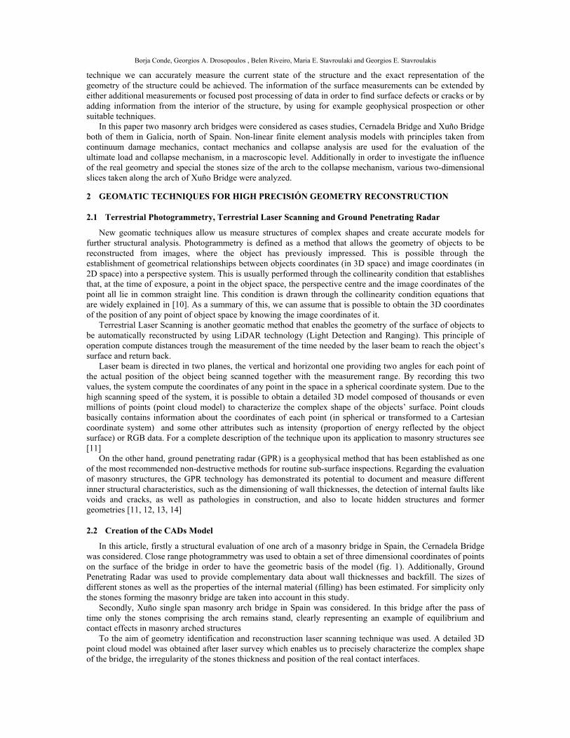
In this article, firstly a structural evaluation of one arch of a masonry bridge in Spain, the Cernadela Bridge was considered. Close range photogrammetry was used to obtain a set of three dimensional coordinates of points on the surface of the bridge in order to have the geometric basis of the model (fig. 1). Additionally, Ground Penetrating Radar was used to provide complementary data about wall thicknesses and backfill. The sizes of different stones as well as the properties of the internal material (filling) has been estimated. For simplicity only the stones forming the masonry bridge are taken into account in this study.
Secondly, Xuño single span masonry arch bridge in Spain was considered. In this bridge after the pass of time only the stones comprising the arch remains stand, clearly representing an example of equilibrium and contact effects in masonry arched structures
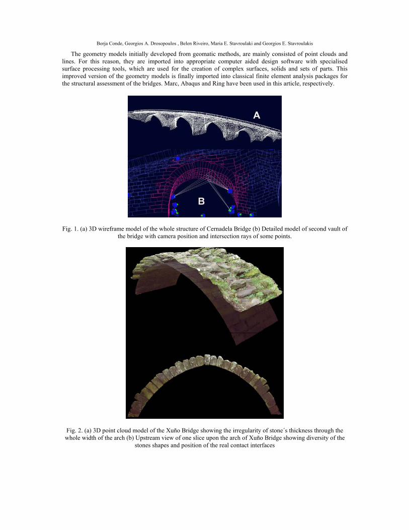
To the aim of geometry identification and reconstruction laser scanning technique was used. A detailed 3D point cloud model was obtained after laser survey which enables us to precisely characterize the complex shape of the bridge, the irregularity of the stones thickness and position of the real contact interfaces.
Borja Conde, Georgios A. Drosopoulos , Belen Riveiro, Maria E. Stavroulaki and Georgios E. Stavroulakis
The geometry models initially developed from geomatic methods, are mainly consisted of point clouds and lines. For this reason, they are imported into appropriate computer aided design software with specialised surface processing tools, which are used for the creation of complex surfaces, solids and sets of parts. This improved version of the geometry models is finally imported into classical finite element analysis packages for the structural assessment of the bridges. Marc, Abaqus and Ring have been used in this article, respectively.
Fig. 1. (a) 3D wireframe model of the whole structure of Cernadela Bridge (b) Detailed model of second vault of the bridge with camera position and intersection rays of some points.
Fig. 2. (a) 3D point cloud model of the Xuño Bridge showing the irregularity of stone´s thickness through the whole width of the arch (b) Upstream view of one slice upon the arch of Xuño Bridge showing diversity of the
stones shapes and position of the real contact interfaces
Borja Conde, Georgios A. Drosopoulos , Belen Riveiro, Maria E. Stavroulaki and Georgios E. Stavroulakis
3 COLLAPSE ANALYSIS
3.1 Finite Element Unilateral Contact Analysis
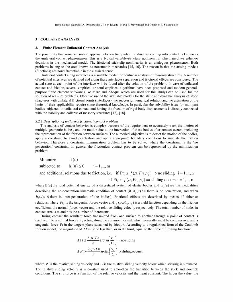
The possibility that some separation appears between two parts of a structure coming into contact is known as the unilateral contact phenomenon. This is a typical variable-structure nonlinearity, which involves either-or decisions in the mechanical model. The frictional stick-slip nonlinearity is an analogous phenomenon. Both problems belong to the area known as nonsmooth mechanics [15, 16]. The reason is that the arising models (functions) are nondifferentiable in the classical sense. Unilateral contact along interfaces is a suitable model for nonlinear analysis of masonry structures. A number of potential interfaces are defined and along these interfaces separation and frictional effects are considered. The actual state at each point of the interface will be found after the solution of the problem. In case of unilateral contact and friction, several empirical or semi-empirical algorithms have been proposed and modern general- purpose finite element software (like Marc and Abaqus which are used for this study) can be used for the solution of real-life problems. Effective use of the available models for the static and dynamic analysis of stone structures with unilateral frictional joints (interfaces), the successful numerical solution and the estimation of the limits of their applicability require some theoretical knowledge. In particular the solvability issue for multipart bodies subjected to unilateral contact and having the freedom of rigid body displacements is directly connected with the stability and collapse of masonry structures [17], [18]. 3.2.1 Description of unilateral frictional contact problem The analysis of contact behavior is complex because of the requirement to accurately track the motion of multiple geometric bodies, and the motion due to the interaction of these bodies after contact occurs, including the representation of the friction between surfaces. The numerical objective is to detect the motion of the bodies, apply a constraint to avoid penetration and apply appropriate boundary conditions to simulate the friction behavior. Therefore a constraint minimization problem has to be solved where the constraint is the ‘no penetration’ constraint. In general the frictionless contact problem can be represented by the minimization problem:
where )(u the total potential energy of a discretized system of elastic bodies and )(uhj are the inequalities
describing the no-penetration kinematic condition of contact (if 0)( uhj there is no penetration, and when
0)( uh j there is inter-penetration of the bodies). Frictional effects are described by means of either-or
relations, where iFt is the tangential forces vector and ),,( ri vFnf is a yield function depending on the friction
coefficient, the normal forces vector and the relative sliding velocity respectively. The total number of nodes in contact area is m and n is the number of increments. During contact the resultant force transmitted from one surface to another through a point of contact is resolved into a normal force Fn , acting along the common normal, which generally must be compressive, and a tangential force Ft in the tangent plane sustained by friction. According to a regularized form of the Coulomb friction model, the magnitude of Ft must be less than, or in the limit, equal to the force of limiting function:
where rv is the relative sliding velocity and C is the relative sliding velocity below which sticking is simulated.
The relative sliding velocity is a constant used to smoothen the transition between the stick and no-stick conditions. The slip force is a function of the relative velocity and the input constant. The larger the value, the
n1,...,i occurs sliding),,(Ft if
n1,...,i sliding no),,(Ft if i.e. friction, todue relations additional and
m1,...,j 0(u)h tosubjected
(u) Minimize
i
i
j
ri
ri
vFnf
vFnf
occurs. slidingarctan2
if
sliding no arctan2
F if
C
vFnFt
C
vFnt
r
r
Borja Conde, Georgios A. Drosopoulos , Belen Riveiro, Maria E. Stavroulaki and Georgios E. Stavroulakis
smaller the force required to generate slip. The computation of Coulomb friction in a contact problem can be based on either nodal stresses or nodal forces. For a given external loading, for example self-weight, the mechanical problem can be solved. By varying the external loading, for example by applying an increasing concentrated loading at some part of the bridge loss of solvability or collapse occurs at some level of loading. The collapse load can be estimated by careful nonlinear finite element analysis.
3.2 Limit Analysis Method
Besides of aforementioned, classical tools exist based on the assumption of rigid blocks with contact relations. Problem is established on the basis of joint equilibrium formulation with constraints related to no tension strength and failure by sliding at interfaces.
The collapse analysis problem is solved by a linear programming formulation aimed at maximize the load factor λ. This load factor identify enable to identify the limit state of the bridge when is applied to a specified live load. If such is less than one, then structure will be unstable. Collapse load of the bridge simple corresponds to the product of the current applied live load by this load factor. We have applied a discrete limit analysis by means of rigid blocks within RING software [21]. 4 APPLICATION TO THE CERNADELA AND XUÑO BRIDGE IN SPAIN
4.1 Data of the Problem
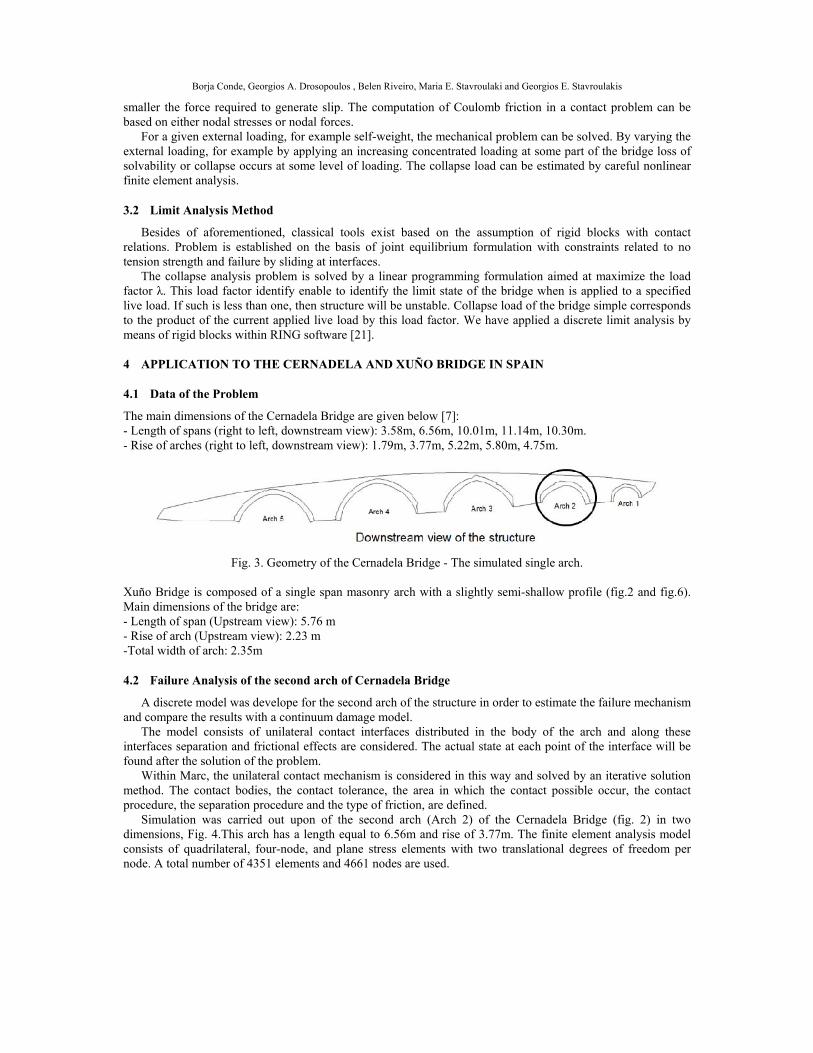
The main dimensions of the Cernadela Bridge are given below [7]: - Length of spans (right to left, downstream view): 3.58m, 6.56m, 10.01m, 11.14m, 10.30m. - Rise of arches (right to left, downstream view): 1.79m, 3.77m, 5.22m, 5.80m, 4.75m.
Fig. 3. Geometry of the Cernadela Bridge - The simulated single arch.
Xuño Bridge is composed of a single span masonry arch with a slightly semi-shallow profile (fig.2 and fig.6). Main dimensions of the bridge are: - Length of span (Upstream view): 5.76 m - Rise of arch (Upstream view): 2.23 m -Total width of arch: 2.35m
4.2 Failure Analysis of the second arch of Cernadela Bridge
A discrete model was develope for the second arch of the structure in order to estimate the failure mechanism and compare the results with a continuum damage model.
The model consists of unilateral contact interfaces distributed in the body of the arch and along these interfaces separation and frictional effects are considered. The actual state at each point of the interface will be found after the solution of the problem.
Within Marc, the unilateral contact mechanism is considered in this way and solved by an iterative solution method. The contact bodies, the contact tolerance, the area in which the contact possible occur, the contact procedure, the separation procedure and the type of friction, are defined.
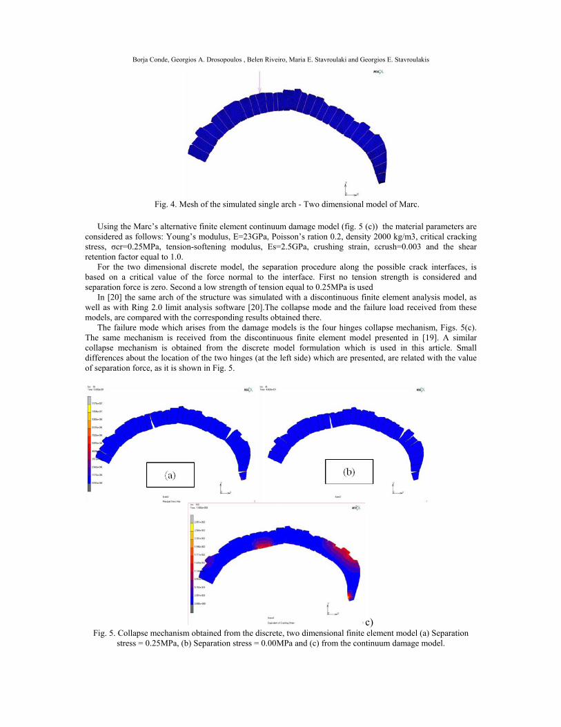
Simulation was carried out upon of the second arch (Arch 2) of the Cernadela Bridge (fig. 2) in two dimensions, Fig. 4.This arch has a length equal to 6.56m and rise of 3.77m. The finite element analysis model consists of quadrilateral, four-node, and plane stress elements with two translational degrees of freedom per node. A total number of 4351 elements and 4661 nodes are used.
Borja Conde, Georgios A. Drosopoulos , Belen Riveiro, Maria E. Stavroulaki and Georgios E. Stavroulakis
Fig. 4. Mesh of the simulated single arch - Two dimensional model of Marc.
Using the Marc’s alternative finite element continuum damage model (fig. 5 (c)) the material parameters are
considered as follows: Young’s modulus, E=23GPa, Poisson’s ration 0.2, density 2000 kg/m3, critical cracking stress, σcr=0.25MPa, tension-softening modulus, Es=2.5GPa, crushing strain, εcrush=0.003 and the shear retention factor equal to 1.0.
For the two dimensional discrete model, the separation procedure along the possible crack interfaces, is based on a critical value of the force normal to the interface. First no tension strength is considered and separation force is zero. Second a low strength of tension equal to 0.25MPa is used
In [20] the same arch of the structure was simulated with a discontinuous finite element analysis model, as well as with Ring 2.0 limit analysis software [20].The collapse mode and the failure load received from these models, are compared with the corresponding results obtained there.
The failure mode which arises from the damage models is the four hinges collapse mechanism, Figs. 5(c). The same mechanism is received from the discontinuous finite element model presented in [19]. A similar collapse mechanism is obtained from the discrete model formulation which is used in this article. Small differences about the location of the two hinges (at the left side) which are presented, are related with the value of separation force, as it is shown in Fig. 5.
c) Fig. 5. Collapse mechanism obtained from the discrete, two dimensional finite element model (a) Separation
stress = 0.25MPa, (b) Separation stress = 0.00MPa and (c) from the continuum damage model.
Borja Conde, Georgios A. Drosopoulos , Belen Riveiro, Maria E. Stavroulaki and Georgios E. Stavroulakis
4.3 Collapse Analysis of the Xuño Bridge
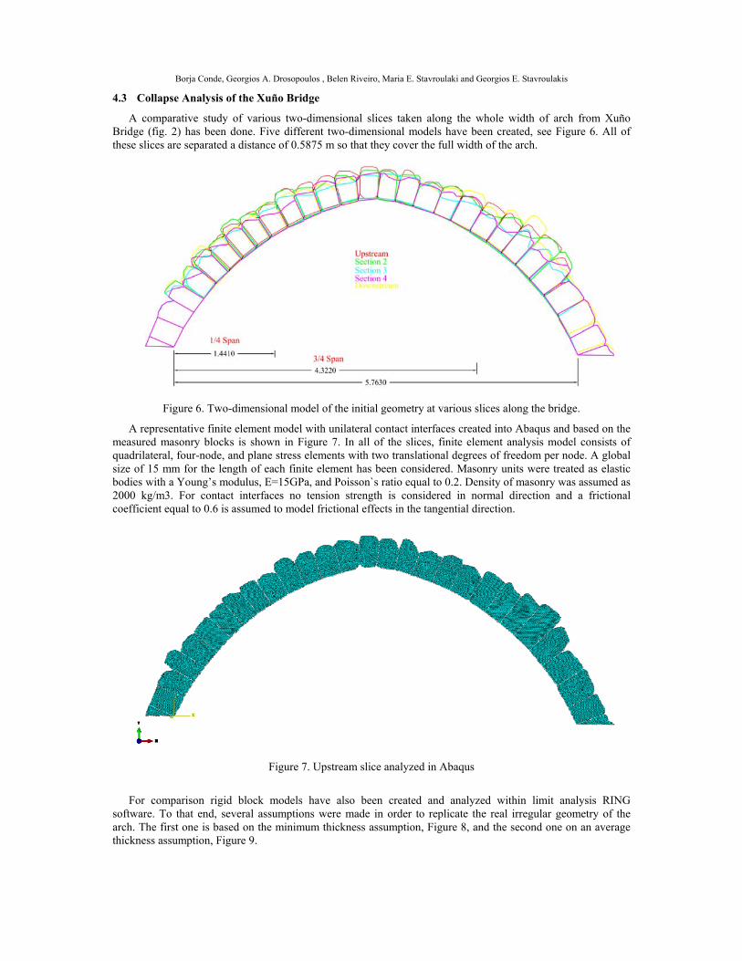
A comparative study of various two-dimensional slices taken along the whole width of arch from Xuño Bridge (fig. 2) has been done. Five different two-dimensional models have been created, see Figure 6. All of these slices are separated a distance of 0.5875 m so that they cover the full width of the arch.
Figure 6. Two-dimensional model of the initial geometry at various slices along the bridge.
A representative finite element model with unilateral contact interfaces created into Abaqus and based on the measured masonry blocks is shown in Figure 7. In all of the slices, finite element analysis model consists of quadrilateral, four-node, and plane stress elements with two translational degrees of freedom per node. A global size of 15 mm for the length of each finite element has been considered. Masonry units were treated as elastic bodies with a Young’s modulus, E=15GPa, and Poisson`s ratio equal to 0.2. Density of masonry was assumed as 2000 kg/m3. For contact interfaces no tension strength is considered in normal direction and a frictional coefficient equal to 0.6 is assumed to model frictional effects in the tangential direction.
Figure 7. Upstream slice analyzed in Abaqus
For comparison rigid block models have also been created and analyzed within limit analysis RING
software. To that end, several assumptions were made in order to replicate the real irregular geometry of the arch. The first one is based on the minimum thickness assumption, Figure 8, and the second one on an average thickness assumption, Figure 9.
Borja Conde, Georgios A. Drosopoulos , Belen Riveiro, Maria E. Stavroulaki and Georgios E. Stavroulakis
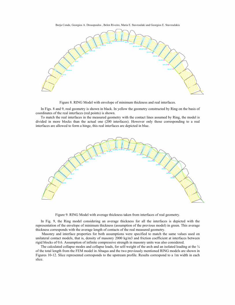
Figure 8. RING Model with envelope of minimum thickness and real interfaces.
In Figs. 8 and 9, real geometry is shown in black. In yellow the geometry constructed by Ring on the basis of coordinates of the real interfaces (red points) is shown.
To match the real interfaces in the measured geometry with the contact lines assumed by Ring, the model is divided in more blocks than the actual one (200 interfaces). However only those corresponding to a real interfaces are allowed to form a hinge, this real interfaces are depicted in blue.
Figure 9. RING Model with average thickness taken from interfaces of real geometry.
In Fig. 9, the Ring model considering an average thickness for all the interfaces is depicted with the representation of the envelope of minimum thickness (assumption of the previous model) in green. This average thickness corresponds with the average length of contacts of the real measured geometry.
Masonry and interface properties for both assumptions were specified to match the same values used on unilateral contact models, that is, density of masonry 2000 kg/m3 and friction coefficient at interfaces between rigid blocks of 0.6. Assumption of infinite compressive strength in masonry units was also considered.
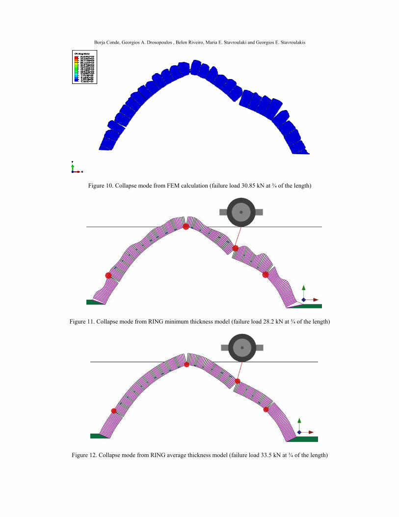
The calculated collapse modes and collapse loads, for self-weight of the arch and an isolated loading at the ¼ of the total length from the FEM model in Abaqus and the two previously mentioned RING models are shown in Figures 10-12. Slice represented corresponds to the upstream profile. Results correspond to a 1m width in each slice.
Borja Conde, Georgios A. Drosopoulos , Belen Riveiro, Maria E. Stavroulaki and Georgios E. Stavroulakis
Figure 10. Collapse mode from FEM calculation (failure load 30.85 kN at ¾ of the length)
Figure 11. Collapse mode from RING minimum thickness model (failure load 28.2 kN at ¾ of the length)
Figure 12. Collapse mode from RING average thickness model (failure load 33.5 kN at ¾ of the length)
Borja Conde, Georgios A. Drosopoulos , Belen Riveiro, Maria E. Stavroulaki and Georgios E. Stavroulakis
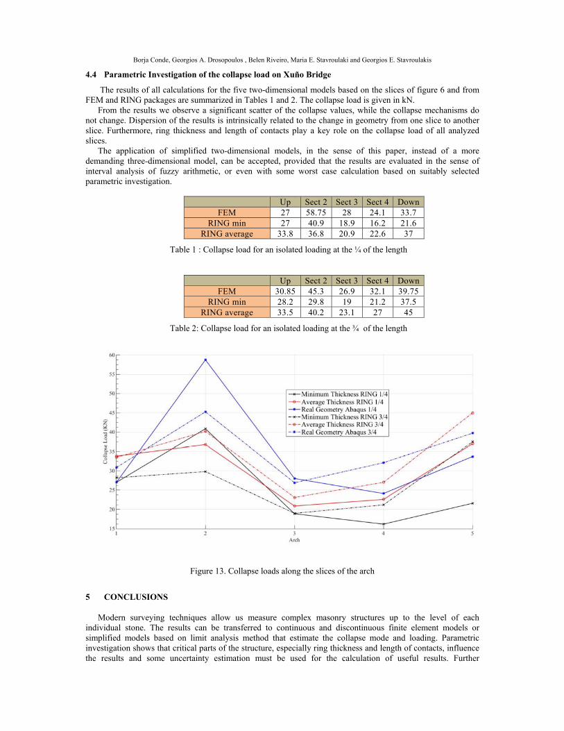
4.4 Parametric Investigation of the collapse load on Xuño Bridge
The results of all calculations for the five two-dimensional models based on the slices of figure 6 and from FEM and RING packages are summarized in Tables 1 and 2. The collapse load is given in kN.
From the results we observe a significant scatter of the collapse values, while the collapse mechanisms do not change. Dispersion of the results is intrinsically related to the change in geometry from one slice to another slice. Furthermore, ring thickness and length of contacts play a key role on the collapse load of all analyzed slices.
The application of simplified two-dimensional models, in the sense of this paper, instead of a more demanding three-dimensional model, can be accepted, provided that the results are evaluated in the sense of interval analysis of fuzzy arithmetic, or even with some worst case calculation based on suitably selected parametric investigation.
Up Sect 2 Sect 3 Sect 4 Down
FEM 27 58.75 28 24.1 33.7 RING min 27 40.9 18.9 16.2 21.6
RING average 33.8 36.8 20.9 22.6 37
Table 1 : Collapse load for an isolated loading at the ¼ of the length
Up Sect 2 Sect 3 Sect 4 Down
FEM 30.85 45.3 26.9 32.1 39.75 RING min 28.2 29.8 19 21.2 37.5
RING average 33.5 40.2 23.1 27 45
Table 2: Collapse load for an isolated loading at the ¾ of the length
Figure 13. Collapse loads along the slices of the arch
5 CONCLUSIONS
Modern surveying techniques allow us measure complex masonry structures up to the level of each individual stone. The results can be transferred to continuous and discontinuous finite element models or simplified models based on limit analysis method that estimate the collapse mode and loading. Parametric investigation shows that critical parts of the structure, especially ring thickness and length of contacts, influence the results and some uncertainty estimation must be used for the calculation of useful results. Further
Borja Conde, Georgios A. Drosopoulos , Belen Riveiro, Maria E. Stavroulaki and Georgios E. Stavroulakis
investigation in this direction will be done in the near future.
REFERENCES
[1] Leftheris B.P., Stavroulaki M.E., Sapounaki A.K., Stavroulakis G.E. (2006), Computational mechanics for
heritage structures. WIT Press, Southampton (UK).
[2] Lourenco, P.B. (2002),’ Computations on historic masonry structures’, Prog Struct Engin Material Vol. 4, (2002) 301-319.
[3] Lourenco, P.B. (2001), ‘Analysis of historical constructions: From thrust-line to advanced simulations’, Historical Constructions, Eds. P.B. Lourenco, P. Roca, Guimaraes, pp. 91-116.
[4] Karaveziroglou, M., Stavrakakis, E., Lazarides P., Liolios, A., Giannopoulou, M., Roukounis, Y., Yeroyianni, M. (2001), ‘A comparative analysis of some historical stone arch bridges in Greece by two new numerical approaches’, Historical Constructions, Eds. P.B. Lourenco, P. Roca, Guimaraes, pp. 749-755.
[5] Hatzigeorgiou, G.D., Beskos, D.E., Theodorakopoulos, D.D., Sfakianakis, M. (1999),’ Static and dynamic analysis of the Arta bridge by finite elements’, FACTA UNIVERSITATIS, Series: Architecture and Civil Engineering, Vol.2, No 1, pp. 41-51.
[6] Gago A.S., Alfaiate J., Gallardo A. (2002), ‘Numerical analyses of the Bargower Arch Bridge’, Proceedings of 3rd World Diana Conference, Tokyo, 8, pp. 257.
[7] Stavroulaki M.E., Stavroulakis G.E. (2002), ‘Unilateral contact applications using FEM software’, in Intern. Journal of Applied Mathematics and Computer Sciences, Special Issue on ‘Mathematical Modeling and Numerical Analysis in Solid Mechanics’, Guest Editors M. Sofonea, J.M. Viano 12(1), pp. 101-111.
[8] Stavroulaki M.E., Sapounaki A.K., Leftheris B.P., Stavroulakis G.E.(2002), ‘Nonlinear finite element for damage analysis of the Plaka stone bridge in Epirus’, GRACM 2002 4th Hellenic Conference of Computational Mechanics, D. Tsahalis (Ed.), University of Patras, Greece, 27-29 June, CD-ROM.
[9] Stavroulaki M.E. (2004), ‘Finite element analysis of a stone bridge for failure prediction’, in 7th National Congress on Mechanics, 24-26 June, Chania, Crete, Greece.
[10] Arias P., Ordonez C., Lorenzo H., Herraez J., Armesto J. (2007), ‘Low-cost documentation of traditional agro-industrial buildings by close-range photogrammetry’, Build Environ 42, pp. 1817–27.
[11] Riveiro, B.; Morer, P.; Arias, P.; de Arteaga, I. Terrestrial laser scanning and limit analysis of masonry arch bridges. Constr. Build. Mater 2011, 25, 1726–1735
[12] Ural A., Oruç Ş., Doğangün A., İskender Ö. (2008), ‘Turkish historical arch bridges and their deteriorations and failures’, Engin Fail Analysis 15, pp. 43–53.
[13] McCann D.M., Forde M.C. (2001), ‘Review of NDT methods in the assessment of concrete and masonry structures’, NDT&E International 34, pp. 71–4.
[14] Solla M., Lorenzo H., Riveiro B, Rial F.I. (2011), ‘Non-destructive methodologies in the assessment of the masonry arch bridge of Traba, Spain’, Engin Fail Analysis 18, pp. 828–35.
[15] Riveiro B., Solla M., I. de Arteaga, Arias P., Morer P. (2013), A novel approach to evaluate masonry arch stability on the basis of limit analysis theory and non-destructive geometric characterization’, Autom Constr 3, pp. 140-48.
[16] Panagiotopoulos P.D. (1985), Inequality problems in mechanics and applications. Convex and nonconvex energy functions, Birkhauser Verlag, Basel, Boston, Stuttgart.
[17] Mistakidis E.S., Stavroulakis G.E. (1998), Nonconvex optimization in mechanics, Smooth and nonsmooth algorithms, heuristics and engineering applications, Kluwer Academic Publishers, Dordrecht.
[18] Drosopoulos G.A., Stavroulakis G.E., and Massalas C.V. (2006), “Limit analysis of a single span masonry bridge with unilateral frictional contact interfases”, Engineering Structures, 28, 1864-1873.
[19] Ferris M., and Tin-Loi F. (2001), “Limit analysis of frictional block assemblies as a mathematical program with complementarity constraints”, Int. J. Mech. Sci., Vol. 43, 209-224.
[20] Riveiro B., Caamaño J.C., Arias P., Sanz E. (2011), ‘Photogrammetric 3D modelling and mechanical analysis of masonry arches: An approach based on a discontinuous model of voussoirs’, Autom Constr, 20, pp. 380–88.

Borja Conde, Georgios A. Drosopoulos , Belen Riveiro, Maria E. Stavroulaki and Georgios E. Stavroulakis
[21] Ring 3.0 Theory & Modelling Guide, LimitState. Sheffield, UK. Available at: http://www.limitstate.com/ring.