influence of design parameters on cogging torque in permanent magnet machines
TRANSCRIPT
IEEE TRANSACTIONS ON ENERGY CONVERSION, VOL. 15, NO. 4, DECEMBER 2000 407
Influence of Design Parameters on Cogging Torquein Permanent Magnet Machines
Z. Q. Zhu, Member, IEEEand David Howe
Abstract—The influence of various design parameters on thecogging torque developed by permanent magnet machines is inves-tigated. It is shown that the slot and pole number combination has asignificant effect on the cogging torque, and influences the optimalvalue of both skew angle and magnet arc, as well as determining theoptimal number of auxiliary teeth/slots. A simple factor, which isproportional to the slot number and the pole number and inverselyproportional to their smallest common multiple, has been intro-duced to indicate the “goodness” of the slot and pole number com-bination. In general, the higher the “goodness” factor the largerthe cogging torque.
Index Terms—Cogging torque, electrical machines, machine de-sign, permanent magnet machines, speed ripple, torque, torqueripple.
I. INTRODUCTION
COGGING torque results from the interaction of perma-nent magnet mmf harmonics and the airgap permeance
harmonics due to slotting. It manifests itself by the tendencyof a rotor to align in a number of stable positions even when themachine is unexcited, and results in a pulsating torque, whichdoes not contribute to the net effective torque. However, sinceit can cause speed ripples and induce vibrations, particularly atlight load and low speed, its reduction is usually a major designgoal [1]–[4].
In the paper, the effect of the slot and pole number combi-nation on the cogging torque is investigated, and its relation-ship with various other design parameters, such as the width ofthe stator slot openings, the magnet arc and the skew angle, aswell as with design features such as auxiliary teeth and slots isconsidered, with respect to machines in which the magnets aremounted adjacent to the airgap.
II. A NALYSIS TECHNIQUES
Cogging torque is produced predominantly as a result offringing fields in the magnet interpole and slot regions [5], atypical cogging torque waveform being shown in Fig. 1. It canbe shown that in a motor having full pole-pitched magnets theinstantaneous cogging torque is zero when a) the interpole axesalign with the centers of teeth, and b) the interpole axes alignwith the centers of slots. However, since a permanent magnetrotor would tend to rotate to a position of maximum storedenergy, case a) corresponds to a stable equilibrium position,
Manuscript received November 9, 1997.The authors are with the Department of Electronic and Electrical Engineering,
University of Sheffield, Mappin Street, Sheffield S1 3JD, UK.Publisher Item Identifier S 0885-8969(00)11017-4.
Fig. 1. Typical cogging torque waveform.
since the leakage flux paths between the edges of north andsouth poles have minimum length, effectively only crossing theairgap, while case b) corresponds to an unstable equilibriumposition, since the leakage flux paths include the slot openings.The positive and negative peaks of the cogging torque occurapproximately when the interpole axes align with the edges ofthe slots.
The electromagnetic torque can be calculated analytically ornumerically in a variety of ways, such as by the Maxwell Stressand co-energy methods. However, they require very accurateglobal and local field solutions [5]–[7], particularly for the de-termination of cogging torque. In other words, a high level ofmesh discretization is required in a finite element calculation,whilst a reliable physical model is essential to an analytical pre-diction. The authors have employed a variety of analytical tech-niques to predict the cogging torque in permanent magnet ma-chine topologies in which the magnets are mounted adjacentto the airgap [8]. Most recently, they extended an analyticalmodel to solve for the magnetic field distribution in the com-bined magnet/airgap/slot regions, albeit with the assumption ofrectangular shaped slots. It provided a very reliable analysis toolfor predicting the cogging torque, and underpins the investiga-tion described in this paper. In general, it is capable of quanti-fying the effects of the following design parameters:
a) slot number and pole number combination, including aux-iliary teeth and slots (optional);
b) slot opening width, airgap length, and magnet thickness;c) magnet pole-arc to pole-pitch ratio;d) magnetization distribution, which may range from regular
to trapezoidal;e) skewing of slots and/or magnets, and the stepped
equivalent;f) disposition of magnets.Throughout, the calculations are for an internal rotor machine
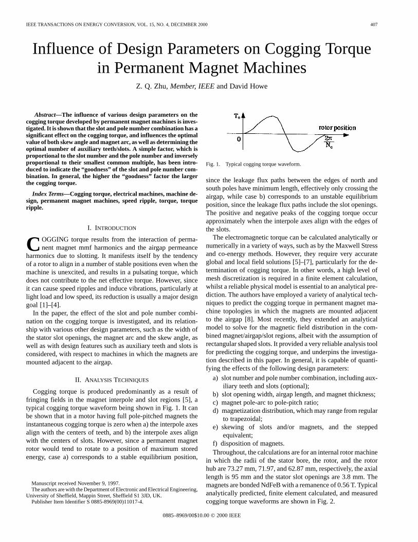
in which the radii of the stator bore, the rotor, and the rotorhub are 73.27 mm, 71.97, and 62.87 mm, respectively, the axiallength is 95 mm and the stator slot openings are 3.8 mm. Themagnets are bonded NdFeB with a remanence of 0.56 T. Typicalanalytically predicted, finite element calculated, and measuredcogging torque waveforms are shown in Fig. 2.
0885–8969/00$10.00 © 2000 IEEE
408 IEEE TRANSACTIONS ON ENERGY CONVERSION, VOL. 15, NO. 4, DECEMBER 2000
Fig. 2. Comparison of analytically/finite element predicted and measuredcogging torque.
III. CHOICE OFSLOT AND POLE NUMBER COMBINATION
The cogging torque can be expressed in the general form:
(1)
where the fundamental order of the waveform,, is thesmallest common multiple between the slot numberand thepole number ; is the mechanical angle between the statorand the rotor, and is the skew factor given by:
(2)
where is the ratio of the total circumferential skew to theslot pitch.
In general, the larger the smallest common multipleandthe smaller the number of slots or poles, then the smaller will bethe amplitude of the cogging torque. However, in order to aid theselection of and , the factor is introduced to denotethe “goodness” of slot and pole number combinations from thepoint of view of cogging torque, where:
(3)
Although there is no formal basis for relating to the am-plitude of the cogging torque, it has been found that the largerthe factor the larger will be the cogging torque.
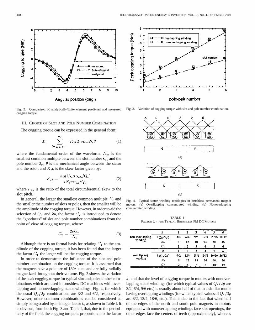
In order to demonstrate the influence of the slot and polenumber combination on the cogging torque, it is assumed thatthe magnets have a pole-arc of 180elec. and are fully radiallymagnetized throughout their volume. Fig. 3 shows the variationof the peak cogging torque for typical slot and pole number com-binations which are used in brushless DC machines with over-lapping and nonoverlapping stator windings, Fig. 4, for whichthe usual combinations are 3/2 and 6/2, respectively.However, other common combinations can be considered assimply being scaled by an integer factor, as shown in Table I. Itis obvious, from both Fig. 3 and Table I, that, due to the period-icity of the field, the cogging torque is proportional to the factor
Fig. 3. Variation of cogging torque with slot and pole number combination.
(a)
(b)
Fig. 4. Typical stator winding topologies in brushless permanent magnetmotors. (a) Overflapping concentrated winding. (b) Nonoverlappingconcentrated winding.
TABLE IFACTORC FOR TYPICAL BRUSHLESSPM DC MOTORS
, and that the level of cogging torque in motors with nonover-lapping stator windings (for which typical values of are3/2, 6/4, 9/6 etc.) is usually about half of that in a similar motorhaving overlapping windings (for which typical values ofare 6/2, 12/4, 18/6, etc.). This is due to the fact that when halfof the edges of the north and south pole magnets in motorsequipped with nonoverlapping windings face slot openings, theother edges face the centers of teeth (approximately), whereas
ZHU AND HOWE: INFLUENCE OF DESIGN PARAMETERS ON COGGING TORQUE IN PERMANENT MAGNET MACHINES 409
Fig. 5. Variation of peak cogging torque with slot number in 2-pole motor.
TABLE IIFACTORC FOR TYPICAL 2-POLE BRUSHEDPM MOTORS
with overlapping windings all edges of magnets would face slotopenings.
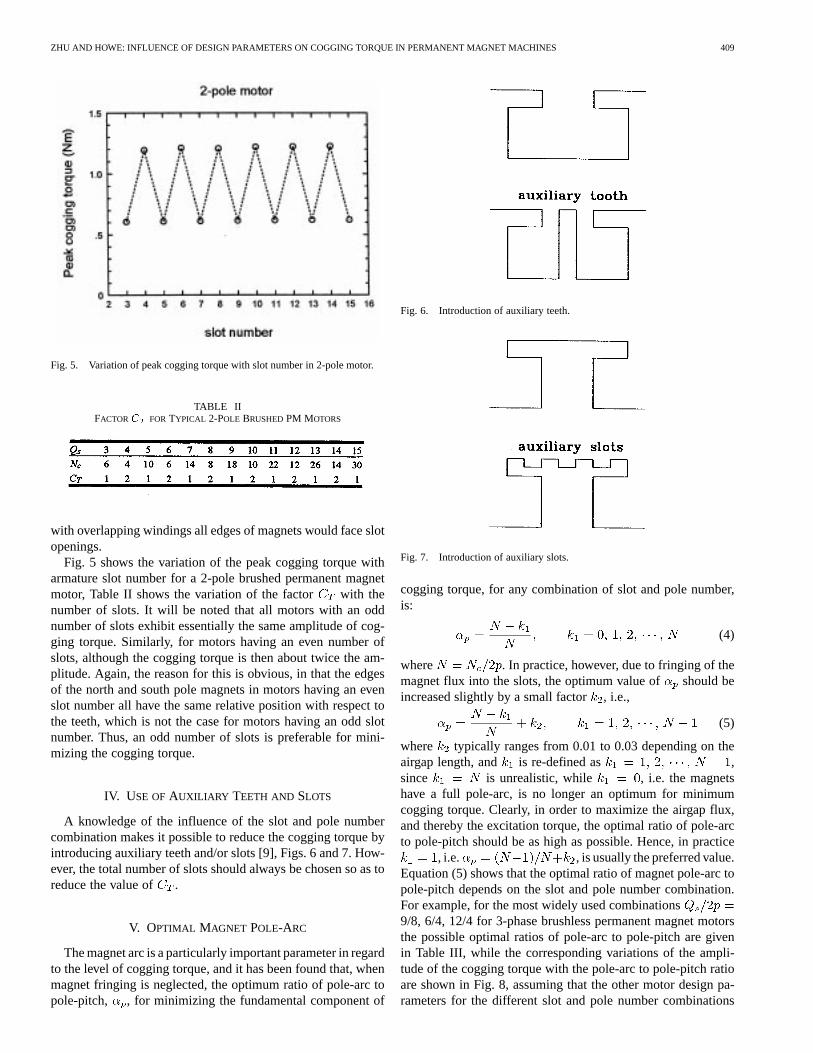
Fig. 5 shows the variation of the peak cogging torque witharmature slot number for a 2-pole brushed permanent magnetmotor, Table II shows the variation of the factor with thenumber of slots. It will be noted that all motors with an oddnumber of slots exhibit essentially the same amplitude of cog-ging torque. Similarly, for motors having an even number ofslots, although the cogging torque is then about twice the am-plitude. Again, the reason for this is obvious, in that the edgesof the north and south pole magnets in motors having an evenslot number all have the same relative position with respect tothe teeth, which is not the case for motors having an odd slotnumber. Thus, an odd number of slots is preferable for mini-mizing the cogging torque.
IV. USE OFAUXILIARY TEETH AND SLOTS
A knowledge of the influence of the slot and pole numbercombination makes it possible to reduce the cogging torque byintroducing auxiliary teeth and/or slots [9], Figs. 6 and 7. How-ever, the total number of slots should always be chosen so as toreduce the value of .
V. OPTIMAL MAGNET POLE-ARC
The magnet arc is a particularly important parameter in regardto the level of cogging torque, and it has been found that, whenmagnet fringing is neglected, the optimum ratio of pole-arc topole-pitch, , for minimizing the fundamental component of
Fig. 6. Introduction of auxiliary teeth.
Fig. 7. Introduction of auxiliary slots.
cogging torque, for any combination of slot and pole number,is:
(4)
where . In practice, however, due to fringing of themagnet flux into the slots, the optimum value of should beincreased slightly by a small factor , i.e.,
(5)
where typically ranges from 0.01 to 0.03 depending on theairgap length, and is re-defined as ,since is unrealistic, while , i.e. the magnetshave a full pole-arc, is no longer an optimum for minimumcogging torque. Clearly, in order to maximize the airgap flux,and thereby the excitation torque, the optimal ratio of pole-arcto pole-pitch should be as high as possible. Hence, in practice
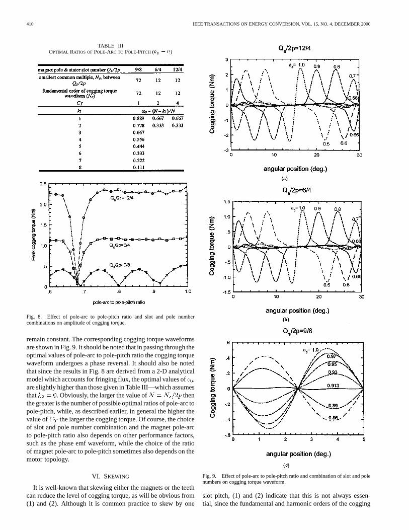
, i.e. , is usually the preferred value.Equation (5) shows that the optimal ratio of magnet pole-arc topole-pitch depends on the slot and pole number combination.For example, for the most widely used combinations9/8, 6/4, 12/4 for 3-phase brushless permanent magnet motorsthe possible optimal ratios of pole-arc to pole-pitch are givenin Table III, while the corresponding variations of the ampli-tude of the cogging torque with the pole-arc to pole-pitch ratioare shown in Fig. 8, assuming that the other motor design pa-rameters for the different slot and pole number combinations
410 IEEE TRANSACTIONS ON ENERGY CONVERSION, VOL. 15, NO. 4, DECEMBER 2000
TABLE IIIOPTIMAL RATIOS OF POLE-ARC TO POLE-PITCH (k = 0)
Fig. 8. Effect of pole-arc to pole-pitch ratio and slot and pole numbercombinations on amplitude of cogging torque.
remain constant. The corresponding cogging torque waveformsare shown in Fig. 9. It should be noted that in passing through theoptimal values of pole-arc to pole-pitch ratio the cogging torquewaveform undergoes a phase reversal. It should also be notedthat since the results in Fig. 8 are derived from a 2-D analyticalmodel which accounts for fringing flux, the optimal values ofare slightly higher than those given in Table III—which assumesthat . Obviously, the larger the value of thenthe greater is the number of possible optimal ratios of pole-arc topole-pitch, while, as described earlier, in general the higher thevalue of the larger the cogging torque. Of course, the choiceof slot and pole number combination and the magnet pole-arcto pole-pitch ratio also depends on other performance factors,such as the phase emf waveform, while the choice of the ratioof magnet pole-arc to pole-pitch sometimes also depends on themotor topology.
VI. SKEWING
It is well-known that skewing either the magnets or the teethcan reduce the level of cogging torque, as will be obvious from(1) and (2). Although it is common practice to skew by one
Fig. 9. Effect of pole-arc to pole-pitch ratio and combination of slot and polenumbers on cogging torque waveform.
slot pitch, (1) and (2) indicate that this is not always essen-tial, since the fundamental and harmonic orders of the cogging
ZHU AND HOWE: INFLUENCE OF DESIGN PARAMETERS ON COGGING TORQUE IN PERMANENT MAGNET MACHINES 411
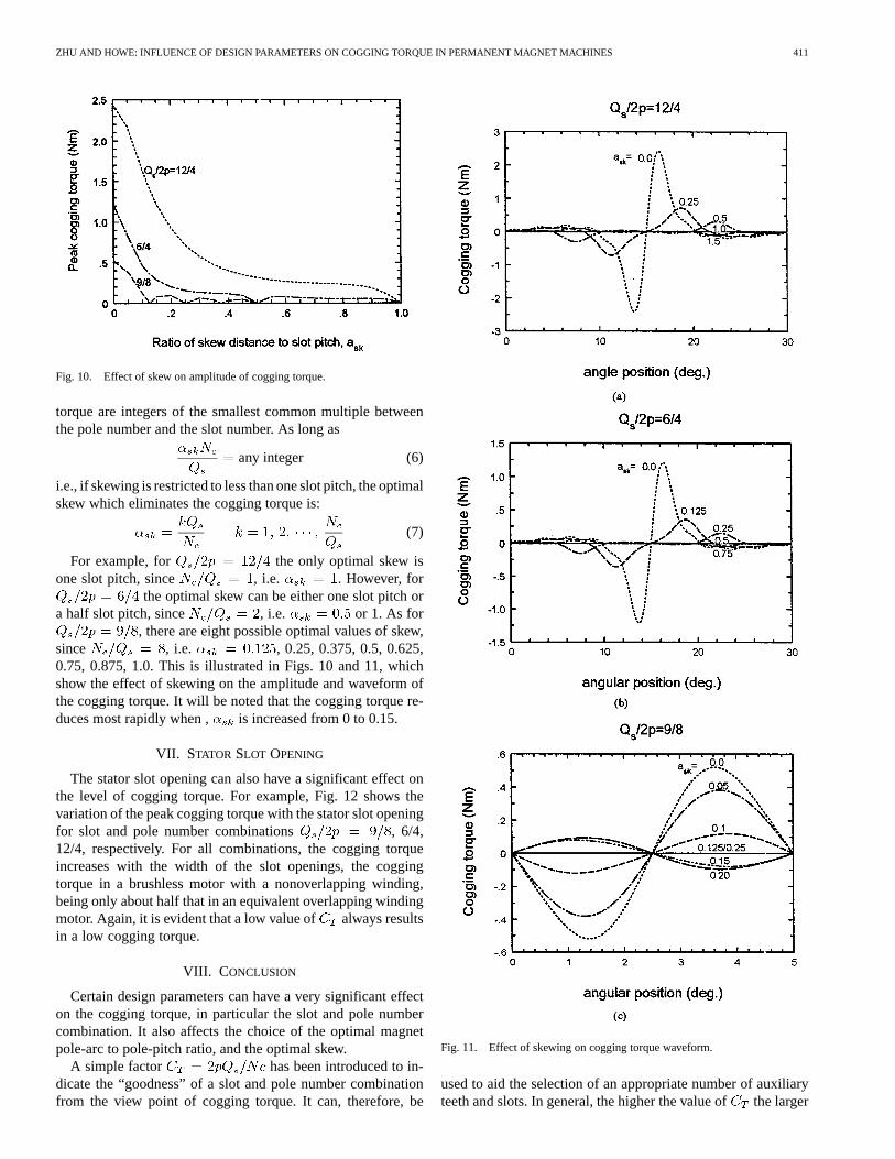
Fig. 10. Effect of skew on amplitude of cogging torque.
torque are integers of the smallest common multiple betweenthe pole number and the slot number. As long as
any integer (6)
i.e., if skewing is restricted to less than one slot pitch, the optimalskew which eliminates the cogging torque is:
(7)
For example, for the only optimal skew isone slot pitch, since , i.e. . However, for
the optimal skew can be either one slot pitch ora half slot pitch, since , i.e. or 1. As for
, there are eight possible optimal values of skew,since , i.e. , 0.25, 0.375, 0.5, 0.625,0.75, 0.875, 1.0. This is illustrated in Figs. 10 and 11, whichshow the effect of skewing on the amplitude and waveform ofthe cogging torque. It will be noted that the cogging torque re-duces most rapidly when , is increased from 0 to 0.15.
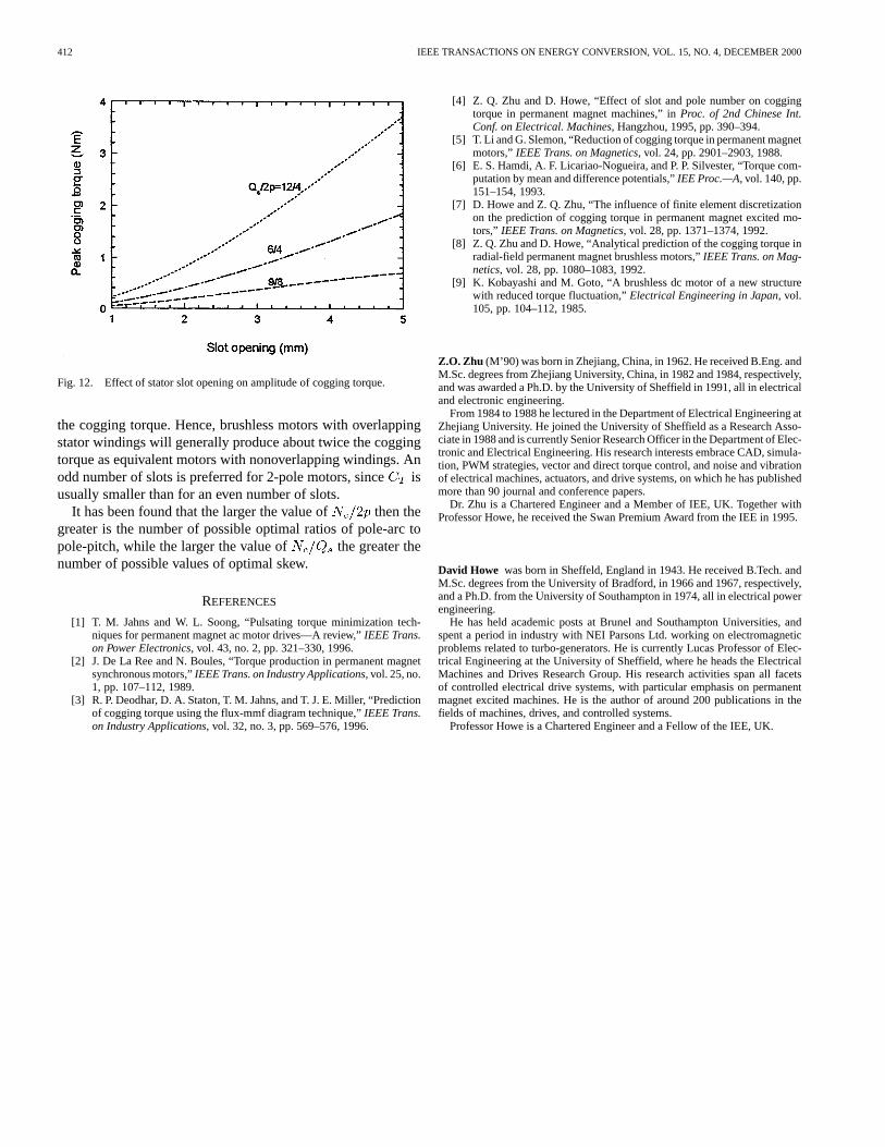
VII. STATOR SLOT OPENING
The stator slot opening can also have a significant effect onthe level of cogging torque. For example, Fig. 12 shows thevariation of the peak cogging torque with the stator slot openingfor slot and pole number combinations , 6/4,12/4, respectively. For all combinations, the cogging torqueincreases with the width of the slot openings, the coggingtorque in a brushless motor with a nonoverlapping winding,being only about half that in an equivalent overlapping windingmotor. Again, it is evident that a low value of always resultsin a low cogging torque.
VIII. C ONCLUSION
Certain design parameters can have a very significant effecton the cogging torque, in particular the slot and pole numbercombination. It also affects the choice of the optimal magnetpole-arc to pole-pitch ratio, and the optimal skew.
A simple factor has been introduced to in-dicate the “goodness” of a slot and pole number combinationfrom the view point of cogging torque. It can, therefore, be
Fig. 11. Effect of skewing on cogging torque waveform.
used to aid the selection of an appropriate number of auxiliaryteeth and slots. In general, the higher the value ofthe larger
412 IEEE TRANSACTIONS ON ENERGY CONVERSION, VOL. 15, NO. 4, DECEMBER 2000
Fig. 12. Effect of stator slot opening on amplitude of cogging torque.
the cogging torque. Hence, brushless motors with overlappingstator windings will generally produce about twice the coggingtorque as equivalent motors with nonoverlapping windings. Anodd number of slots is preferred for 2-pole motors, sinceisusually smaller than for an even number of slots.
It has been found that the larger the value of then thegreater is the number of possible optimal ratios of pole-arc topole-pitch, while the larger the value of the greater thenumber of possible values of optimal skew.
REFERENCES
[1] T. M. Jahns and W. L. Soong, “Pulsating torque minimization tech-niques for permanent magnet ac motor drives—A review,”IEEE Trans.on Power Electronics, vol. 43, no. 2, pp. 321–330, 1996.
[2] J. De La Ree and N. Boules, “Torque production in permanent magnetsynchronous motors,”IEEE Trans. on Industry Applications, vol. 25, no.1, pp. 107–112, 1989.
[3] R. P. Deodhar, D. A. Staton, T. M. Jahns, and T. J. E. Miller, “Predictionof cogging torque using the flux-mmf diagram technique,”IEEE Trans.on Industry Applications, vol. 32, no. 3, pp. 569–576, 1996.
[4] Z. Q. Zhu and D. Howe, “Effect of slot and pole number on coggingtorque in permanent magnet machines,” inProc. of 2nd Chinese Int.Conf. on Electrical. Machines, Hangzhou, 1995, pp. 390–394.
[5] T. Li and G. Slemon, “Reduction of cogging torque in permanent magnetmotors,”IEEE Trans. on Magnetics, vol. 24, pp. 2901–2903, 1988.
[6] E. S. Hamdi, A. F. Licariao-Nogueira, and P. P. Silvester, “Torque com-putation by mean and difference potentials,”IEE Proc.—A, vol. 140, pp.151–154, 1993.
[7] D. Howe and Z. Q. Zhu, “The influence of finite element discretizationon the prediction of cogging torque in permanent magnet excited mo-tors,” IEEE Trans. on Magnetics, vol. 28, pp. 1371–1374, 1992.
[8] Z. Q. Zhu and D. Howe, “Analytical prediction of the cogging torque inradial-field permanent magnet brushless motors,”IEEE Trans. on Mag-netics, vol. 28, pp. 1080–1083, 1992.
[9] K. Kobayashi and M. Goto, “A brushless dc motor of a new structurewith reduced torque fluctuation,”Electrical Engineering in Japan, vol.105, pp. 104–112, 1985.
Z.O. Zhu (M’90) was born in Zhejiang, China, in 1962. He received B.Eng. andM.Sc. degrees from Zhejiang University, China, in 1982 and 1984, respectively,and was awarded a Ph.D. by the University of Sheffield in 1991, all in electricaland electronic engineering.
From 1984 to 1988 he lectured in the Department of Electrical Engineering atZhejiang University. He joined the University of Sheffield as a Research Asso-ciate in 1988 and is currently Senior Research Officer in the Department of Elec-tronic and Electrical Engineering. His research interests embrace CAD, simula-tion, PWM strategies, vector and direct torque control, and noise and vibrationof electrical machines, actuators, and drive systems, on which he has publishedmore than 90 journal and conference papers.
Dr. Zhu is a Chartered Engineer and a Member of IEE, UK. Together withProfessor Howe, he received the Swan Premium Award from the IEE in 1995.
David Howe was born in Sheffeld, England in 1943. He received B.Tech. andM.Sc. degrees from the University of Bradford, in 1966 and 1967, respectively,and a Ph.D. from the University of Southampton in 1974, all in electrical powerengineering.
He has held academic posts at Brunel and Southampton Universities, andspent a period in industry with NEI Parsons Ltd. working on electromagneticproblems related to turbo-generators. He is currently Lucas Professor of Elec-trical Engineering at the University of Sheffield, where he heads the ElectricalMachines and Drives Research Group. His research activities span all facetsof controlled electrical drive systems, with particular emphasis on permanentmagnet excited machines. He is the author of around 200 publications in thefields of machines, drives, and controlled systems.
Professor Howe is a Chartered Engineer and a Fellow of the IEE, UK.