chapter 5 analysis of cogging torque -...
TRANSCRIPT

95
CHAPTER 5
ANALYSIS OF COGGING TORQUE
5.1 INTRODUCTION
In modern era of technology, permanent magnet AC and DC
motors are widely used in many industrial applications. For such motors, it
has been a challenge for the designers to minimize the torque fluctuations
which may cause vibrations, noise and speed fluctuations. These factors have
two key components: torque ripple and cogging torque (Zhu & Howe 2000).
Torque ripple is caused by the fluctuations generated in the field distribution
and the armature MMF. Cogging torque is caused by the interaction between
the stator air-gap permeance and permanent magnet MMF. Cogging torque is
the main source of creating the torque ripple in PM machines. When the
motor runs at high speed, the torque ripple is usually filtered out by the
system inertia. In the case of lower speeds, torque ripple may result in
undesirable speed variations, vibrations, and acoustic noise. Due to this, the
machine performance is affected significantly. Reducing cogging torque is
often a major concern during the design of PM machines, since it is one of the
main sources of speed fluctuations. Figure 5.1 shows the variation of cogging
torque of the proposed PMSRM with respect to different rotor positions. It is
observed that the cogging torque of 1.2 N-m was generated by the proposed
PMSRM which is to be reduced. If the cogging torque is reduced, the overall
torque generated by the machine and its performance could improve to satisfy
the optimum performance.

96
Figure 5.1 Cogging torque of the proposed PMSRM
In order to eliminate the cogging torque theoretically, it is very
important to investigate the equations which define it. In practice, however,
the cogging torque cannot actually be eliminated, but it can be reduced (Zhu
et al 2003). In the most fundamental form cogging torque can be represented
as (Hanselman 1994):
ddRT gcog
2
21 (5.1)
where,
g is the air-gap flux and
R is the air-gap reluctance.

97
From Equation (5.1), cogging torque can be reduced either by
forcing the air-gap flux g , or the rate of change of air-gap reluctanceddR , to
be zero. It is not possible to make g as zero because some amount of air-gap
flux is needed for the alignment and reluctance torque components for driving
the machine. Therefore, the better option for reducing the cogging torque is
to force the air-gap reluctance to be a constant with respect to the position of
rotor.
Cogging torque can be represented in terms of Fourier series as
1)sin(
kcmkcog mkTT (5.2)
where,
m is the least common multiple of the number of stator slots and
the number of poles
ck is an integer
Tmk is a Fourier coefficient and
is angular position of rotor
It is because, cogging torque is a summation of sinusoidal harmonic
component. In case of traditional machines, where there are no cogging
torque reduction techniques, the rotor magnets will contribute an additive
effect to cogging torque. It is because each magnet has the same relative
position with respect to the stator slots. The torque generated from each
magnet is in phase with the others, and as a result, the harmonic components
of each are added. By properly designing a machine in such a way that the
magnets are out of phase with each other the effect of cogging can be
minimized.

98
5.2 METHODS OF REDUCING COGGING TORQUE
Various techniques used for reducing the cogging torque are
discussed in this chapter. Most of the techniques used are successful in
reducing the undesired cogging torque, but they also reduce the desired
mutual torque (Islam et al 2004; Ishikawa 1993). Conventional methods to
reduce cogging torque are (Li & Slemon 1988):
• Using increased length of the air-gap
• Using fractional slots/pole
• Decreasing the width of the slot openings
Using the increased air-gap length to decrease the cogging will
increase the amount of the PM material, because low permeability of the air
will rapidly increase the required MMF (Hwang et al 2001). Fractional
slot/pole design will make the machine design more complicated, and it also
leads to a higher harmonic content of the air-gap flux. It was shown by (Li &
Slemon 1988), however, that with a proper design, the torque ripple of a
fractional slot machine can be kept small. If the slot openings with decreased
widths or even with semi-magnetic slot wedges are applied, the tooth-tip and
the slot-leakage inductance will increase thus decreasing the torque
production capability of the motor. It is also possible to decrease the cogging
torque not only by the proper machine design, but also by modulating the
inverter current waveform. Numerous papers have been written on this topic,
as well as on the other control-based methods (Jahns & Soong 1996; Bianchi
& Bolognani 2002; DeLaRee & Boules 1989). With the increased interest of
the researchers, many new methods of reducing the cogging torque has been
introduced in recent years (Dosiek & Pillay 2007). The most common
methods of reducing cogging torque is discussed in this chapter and a better
method is opted for the design of proposed PMSRM.

99
5.2.1 Introduction of Shoes in Stator Teeth
The simplest and easiest way to eliminate cogging torque is to
design a slot-less stator so that the saliency is eliminated. This type of design
enables the generation of a constant air-gap reluctance that would minimize
the cogging torque. However, in practice, this is not a feasible method due to
the requirement of opening for winding. The alternate solution of reducing the
cogging torque is by the addition of shoes to the stator teeth as shown in
Figure 5.2.
Figure 5.2 Air-gap reluctance with shoes in stator teeth
The addition of shoes allow the stator inner surface to be mostly
steel, thereby decreasing the air-gap reluctance variation. This type of
arrangement also allows space for the insertion of the stator windings. In
general, it is established that the variation in the magnitude of the cogging
torque decreases with increased shoe size. Apart from reducing cogging
torque, the main advantage with the addition of shoes is that the performance
of the machine is not affected by this method. The disadvantage is that
winding inductance is increased. The value of cogging torque with respect to

100
different slot openings is illustrated in Figure 5.3. It is observed that the value
of cogging torque is minimum with no slot opening. It is practically not
possible because the stator windings needed to get into the slots. The actual
size of the shoes is selected so that the slot opening would be just large
enough to allow the stator windings to fit. This value created a slot opening of
2mm. Also, it is seen that the value of cogging torque is nominal when the
slot opening is at 2mm.
Figure 5.3 Cogging torque as a function of slot opening
5.2.2 Optimal Magnet Arc
Magnet pole-arc is a well established technique that can have a
large effect on the amplitude of cogging torque. For minimizing the value of
cogging torque, there is an optimum value for pole-arc that can be found
using
,1sm
m Nn
10 (5.3)

101
where,
m is the ratio of pole-arc to pole-pitch
n is an integer
Nsm is the number of slots per pole and
is the parameter that is varied to minimize cogging
For any given value of n, there exist i values of that can
minimize the ith harmonic of the cogging torque. Determining the proper
values of is not trivial and requires the use of FEM. Finite element method
determines the magnet pole-arc that can minimize cogging torque by
changing several values of magnet arc shown in Figure. 5.4.
Figure 5.4 Cogging torque as a function of magnet arc
102
The angle of the arc was varied for values of n between 4 and 5 to
satisfy Equation (5.3). It was observed that an arc of 105 degree electrical
produces lower cogging torque of 0.43N-m.
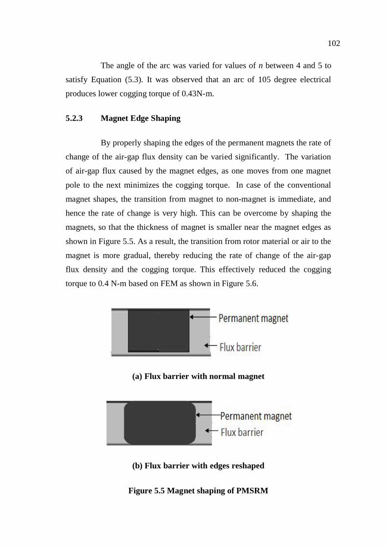
5.2.3 Magnet Edge Shaping
By properly shaping the edges of the permanent magnets the rate of
change of the air-gap flux density can be varied significantly. The variation
of air-gap flux caused by the magnet edges, as one moves from one magnet
pole to the next minimizes the cogging torque. In case of the conventional
magnet shapes, the transition from magnet to non-magnet is immediate, and
hence the rate of change is very high. This can be overcome by shaping the
magnets, so that the thickness of magnet is smaller near the magnet edges as
shown in Figure 5.5. As a result, the transition from rotor material or air to the
magnet is more gradual, thereby reducing the rate of change of the air-gap
flux density and the cogging torque. This effectively reduced the cogging
torque to 0.4 N-m based on FEM as shown in Figure 5.6.
(a) Flux barrier with normal magnet
(b) Flux barrier with edges reshaped
Figure 5.5 Magnet shaping of PMSRM

103
Figure 5.6 Comparison of cogging torque of original machine and
magnet reshaped machine
5.2.4 Skewing
Generally skewing is performed either in the stator or in the rotor
along the axial length of the machine as shown in Figure 5.7. Skewing is one
of effective method to eliminateddR . For an unskewed machine, the value of
instantaneous air-gap reluctance is uniform along the axial length. The
reluctance varies with the period as the rotor rotates, thus generating cogging
torque. The stator or rotor of a machine is skewed in such a way that the total
circumferential angle of skewing is equal to one period of the air-gap
reluctance variation. Each permanent magnet is instantaneously subjected to
the variation of reluctance and thus the value of the cogging torque is varied.
1 0
sin1k
mks
cog
s
dmkTT (5.4)

104
Figure 5.7 Machine with skewed magnet
Where,
s is one period of cogging torque which is obtained from:
ms2 (5.5)
Figure 5.8 Cogging torque with skewing effect

105
The required angle of skewing to eliminate cogging torque was
chosen to be 15 degrees from Equation (5.5). It was found in results shown in
Figure 5.8 that the cogging torque is reduced to 0.35 N-m.
Although continuous skewing theoretically reduces cogging torque,
some residual will still remain in practice due to end effects and rotor
eccentricity. Skewing along with reducing the cogging, also removes most of
the harmonics of the back EMF. The problem of skewing is that it adds torque
ripple in the machines fed with trapezoidal currents. Also skewing includes
the difficulty in manufacturing and an increased winding resistance in the
case of the skewed stator.
5.2.5 Fractional Pitch Winding
In machines that have integral pitch windings, it is common that the
poles will have a whole number which is in multiple of stator teeth. Thus the
cogging effects of each magnet are in phase and added. The cogging torque
generated by each magnet is given by:
1sin
kslkNcog kNTT
s (5.6)
The fundamental frequency of Equation (5.6) is Nsl (number of slot)
times one mechanical rotation. Hence in the case of integral pitch wound
machines, the least common multiple of the number slots and the number of
poles, is equal to Ns. It is because for such type of machines the number of
slots present is an integer multiple of the number of poles. By using a
fractional pitch winding, each magnet pole is subjected to a fractional number
of slots and therefore, the cogging torque contributed by the magnets is out of
phase with each other. As a result, the overall cogging torque is minimized.
For fractional pitch windings, the least common multiple of the number of
slots, number of poles, and the fundamental frequency of the overall cogging

106
torque, is always an integer multiple of the number of slots. Figure 5.9 shows
the cogging torque for the fractional pitch winding. The value of cogging
torque is observed as 0.45 N-m.
Figure 5.9 Cogging torque of fraction pitch winding design
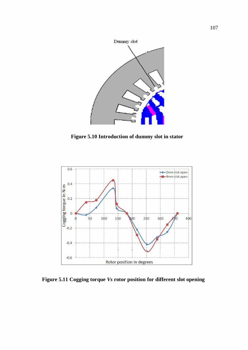
5.2.6 Auxiliary Slotting
By adding some dummy slots in the stator tooth cogging torque can
be minimized. The dummy slots vary the permeance of the stator to reduce
the cogging torque. Dummy slots with the opening of 2mm are shown in
Figure 5.10.
The variation of cogging torque for 2mm and 4mm slot opening is
illustrated in Figure 5.11. It is clear from the results that lower the width of
slot opening, the cogging torque is reduced. The effect of including dummy
slot is almost equivalent to doubling the number of slots which will increase
the cost of production and complexity of design. Hence such methods are not
advisable.
107
Figure 5.10 Introduction of dummy slot in stator
Figure 5.11 Cogging torque Vs rotor position for different slot opening
108
5.3 SUMMARY
The proposed machine is found to have a cogging torque of 1.2N-m
which is 12.5% of the rated torque of the machine. Various techniques for
reducing this cogging torque are discussed.
The first method analyzed for reducing cogging torque is the
addition of shoe to the stator teeth. The value of cogging torque is estimated
for different slot openings. It is found that when the slot opening is at 2mm
the cogging torque is reduced to 25% with the value of 0.9N-m. The lower
value of slot opening can further reduce the cogging torque, but stator
winding cannot be easily fixed. This method does not reduce the cogging
torque significantly.
In optimal magnet arc technique, the angle of arc is varied in steps
of 5 degrees. It is observed that the cogging torque is reduced to 65% with the
value of 0.42 N-m at 105 degrees. The problem with this technique is that the
value of back emf is increased due to increase in arc angle.
Magnetic shaping is one of the easiest techniques to implement
without changing the stator or rotor construction. Only the edges of the
magnets are reshaped to evenly distribute the air-gap flux. The cogging torque
is effectively reduced to 67% with the value of 0.4 N-m.
On skewing the rotor, cogging torque is reduced to a minimum
value of 0.35N-m. However this method increases the manufacturing cost
and complexity in design.
Use of fractional pitch winding reduces the cogging torque to a
value of 0.45N-m. This method is not attractive due to the complexity
involved in winding construction.

109
On adding auxiliary slotting in stator, cogging torque can be
reduced to 70% with the value of 0.35N-m. Due to the introduction of dummy
slots, the stator area is to be increased which increases the size of the machine
as well as cost.
On analyzing various techniques it is proposed to implement the
magnetic shaping method because, it is easy to implement and effectively
reduces the cogging torque up to 67% with the value of 0.4N-m.