influence of cable sliding on the … with stacked arches structures, ... it consists of...
TRANSCRIPT
Advanced Steel Construction Vol. 8, No. 1, pp. 54-70 (2012) 54
INFLUENCE OF CABLE SLIDING ON THE STABILITY OF SUSPEN-DOME WITH STACKED ARCHES STRUCTURES
Liu Hongbo1 and Chen Zhihua1, 2, *
1 Department of Civil Engineering, Tianjin University, Tianjin 300072, China
2 Tianjin Key Laboratory of Civil Engineering Structures and New Materials, Tianjin 300072, China *(Corresponding author: E-mail: [email protected])
Received: 10 March 2011; Revised: 31 May 2011; Accepted: 10 June 2011
ABSTRACT: A new type of continuous cable joint is presented in this paper for the suspen-dome with stacked arch. For this new cable joint, there are two state: locked state and unlocked state. In the locked state, the hoop cable cannot slide around cable joint. In the unlocked state, the hoop cable can slide around cable joint. In order to analyze the stability of suspen-dome with stacked arches structures under condition that the continuous cable joint is unlocked state, A three-node sliding cable element was used and its tangent stiffness matrix was determined based on the principal of virtual work and uniform strain assumption. The element was then implemented in commercial finite element software ABAQUS as a user defined element and applied in the stability analysis of a suspen-dome with stacked arches structure. Both symmetric and asymmetric load were considered for the suspen-dome with stacked arches structure to investigate the influence of cable joint state on its stability behavior. It was concluded that the stability behavior when the continuous cable joint is locked is better than that of when the continuous cable joint is unlocked.
Keywords: Suspen-dome with stacked arch structures, Continuous cable joint, Sliding cable element, Stability
1. INTRODUCTION
Steel cables are widely adopted in long-span structures due to their high strength and low self-weight. By pre-stressing the steel cables, more effective structures can be achieved to span larger distance, such as suspen-dome structures [1], beam string structures [2], cable dome [3], Cable supported barrel vault structure [4] and so on. Suspen-dome structure has been widely applied as roof structures in many buildings, such as Hikarigaoka dome and Fureai dome in Japan, Badminton Gymnasium for 2008 Beijing Olympic Games in China, and Jinan Olympic sports center’s gymnasium for the 2009 11th National Olympic Games in China. Arch structures are a traditional structure, and it can cover long span. Introducing arch structures into grid structures, some effective structures can be also achieved to span longer distance, such as the roof structures of Huhhot Airport and Yangtze River Flood-control Model-testing Hall [5]. In order to form a more effective structure, suspen-dome with stacked arch structure was presented by combining the suspen-dome structures and arch structures, which has been adopted in the roof structure of Chiping Gymnasium. The suspen-dome with stacked arch structure is to use the advantages of arch structures to enhance the suspen-dome structures. Thus the integral mechanical behaviour of the new hybrid structures is efficiently improved, the structural span can be increased and the architectural shapes of large-span structures are also enriched. Therefore, suspen-dome with stacked arch structures have been developed, as a kind of new large-span space structural system. Many investigations have been performed for the suspen-dome structures through experimental research and numerical analysis. Therefore, the fundamental properties for these structures can be well understood [3-12]. Due to the existence of arch, the structural behavior of suspen-dome with stacked arch structure is different from suspen-dome structures. Therefore, it is desired to conduct some research on the structural behavior of suspen-dome with stacked arch structure.
55 Liu Hongbo and Chen Zhihua
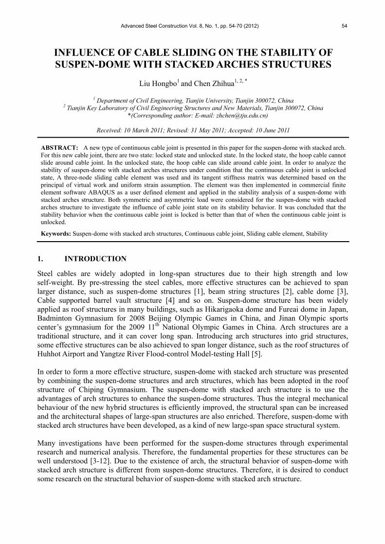
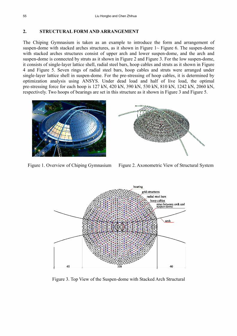
2. STRUCTURAL FORM AND ARRANGEMENT The Chiping Gymnasium is taken as an example to introduce the form and arrangement of suspen-dome with stacked arches structures, as it shown in Figure 1~ Figure 6. The suspen-dome with stacked arches structures consist of upper arch and lower suspen-dome, and the arch and suspen-dome is connected by struts as it shown in Figure 2 and Figure 3. For the low suspen-dome, it consists of single-layer lattice shell, radial steel bars, hoop cables and struts as it shown in Figure 4 and Figure 5. Seven rings of radial steel bars, hoop cables and struts were arranged under single-layer lattice shell in suspen-dome. For the pre-stressing of hoop cables, it is determined by optimization analysis using ANSYS. Under dead load and half of live load, the optimal pre-stressing force for each hoop is 127 kN, 420 kN, 390 kN, 530 kN, 810 kN, 1242 kN, 2060 kN, respectively. Two hoops of bearings are set in this structure as it shown in Figure 3 and Figure 5.
Figure 1. Overview of Chiping Gymnasium Figure 2. Axonometric View of Structural System
Figure 3. Top View of the Suspen-dome with Stacked Arch Structural

Influence of Cable Sliding on the Stability of Suspen-dome with Stacked Arches Structures 56
Figure 4. Axonometric View of Suspen-dome Structure
Figure 5. Sectional View of Suspen-dome Structure
Figure 6. Arch Structure In practice, two kinds cable joints are usually considered for suspen-dome structures. One is non-continuous cable joint as shown in Figure 7, and the other is continuous cable joint as shown in Figure 8. If the non-continuous cable joint is adopted, the two adjacent hoop cables are independent and the hoop cables cannot slide around joints. Comparatively, if the continuous cable joint is adopted, each circumference hoop cable is a continuous cable and the hoop cable can slide around joints. Therefore, the continuous cable joint must be used when the pre-stressing is introduced by tensioning hoop cables.
57 Liu Hongbo and Chen Zhihua
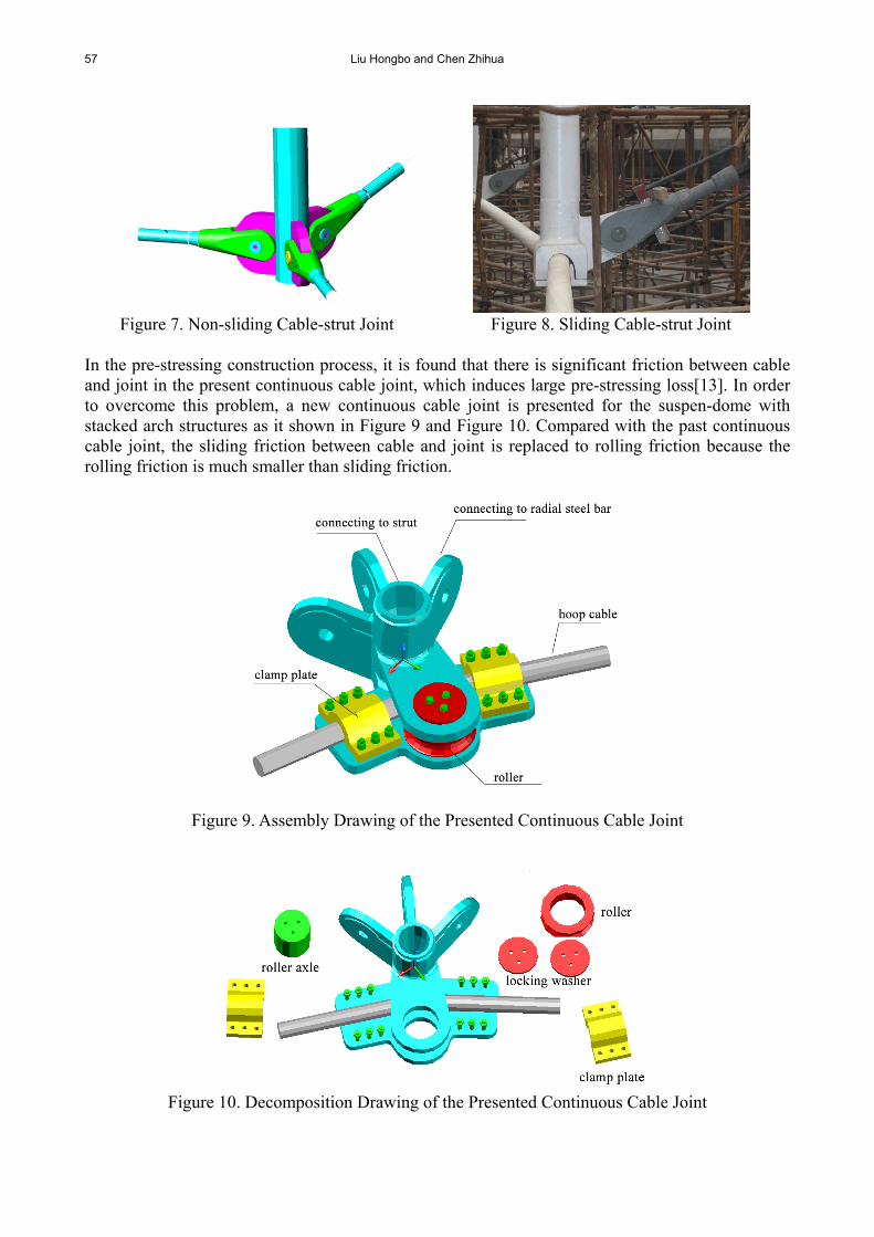
Figure 7. Non-sliding Cable-strut Joint Figure 8. Sliding Cable-strut Joint
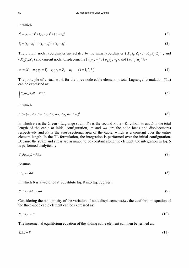
In the pre-stressing construction process, it is found that there is significant friction between cable and joint in the present continuous cable joint, which induces large pre-stressing loss[13]. In order to overcome this problem, a new continuous cable joint is presented for the suspen-dome with stacked arch structures as it shown in Figure 9 and Figure 10. Compared with the past continuous cable joint, the sliding friction between cable and joint is replaced to rolling friction because the rolling friction is much smaller than sliding friction.
Figure 9. Assembly Drawing of the Presented Continuous Cable Joint
Figure 10. Decomposition Drawing of the Presented Continuous Cable Joint

Influence of Cable Sliding on the Stability of Suspen-dome with Stacked Arches Structures 58
The new continuous cable joint has two states. One is locked state and the cable is locked by clamp plates in this state. The other is unlocked state and the cable is unlocked by clamp plates in this state. In the pre-stressing construction, the unlocked state is used. For the usage stage, it is confused for the best state choice. In order to choose a rational joint state, the stability behavior of suspen-dome with stacked arch structures is investigated under both locked state and unlocked state. 3. THREE-NODE SLIDING CABLE ELEMENT In suspen-dome with stacked arches structures, the hoop cable usually threads through a number of cable-strut joints. If the non-sliding cable-strut joint used, the cables can then be simplified as 2-node straight bar elements separated by adjacent joints in finite element analysis. If the sliding cable-strut joint is used, the above simplification may cause significant error due to the neglect of cable sliding. Some techniques have been presented to consider the cable sliding based on finite element analysis with simplified separate cable elements [14-16]. They all need manual iteration intervened by engineers, which are time consuming especially for large scale cable structures. Formulating sliding cable element is a more convenient way to simulate sliding cables. Sliding cable elements have been developed and verified for the analysis of parachute systems [17]. In this paper, a tangent stiffness matrix of three-node sliding cable element was determined based on the principle of virtual work and total Lagrange formulation presented in reference 17. The element was then implemented in commercial finite element software ABAQUS as a user defined element [18]. A three-node cable element is as shown in Figure 11. The cable element has three node, node 1, node 2 and node 3, and each node has three displacement degrees of freedom. The fundamental kinematic assumption of the three-node cable element states that: (1) the cable remains straight between adjacent nodes; (2) the self-weight of the cable can be ignored and all the loads act directly on the nodes; (3) the strain is uniform along the element, i.e., the strain in all segments of the cable is the same at any time; (4) the sliding node can not slide across the adjacent nodes along the cable, which means the order of the nodes along the cable remains unchanged.
Figure 11. A Three-node Cable Element The current element length is determined from the current nodal coordinates ( 1, 1 1,x y z ) , ( 2, 2 2,x y z ) ,
and ( 3, 3 3,x y z ) as
1 2l l l (1)
59 Liu Hongbo and Chen Zhihua
In which
2 2 2 21 3 1 3 1 3 1( ) ( ) ( )l x x y y z z (2)
2 2 2 22 3 2 3 2 3 2( ) ( ) ( )l x x y y z z (3)
The current nodal coordinates are related to the initial coordinates ( 1, 1 1,X Y Z ) , ( 2, 2 2,X Y Z ) , and
( 3, 3 3,X Y Z ) and current nodal displacements ( 1, 1 1,u v w ) , ( 2, 2 2,u v w ), and ( 3, 3 3,u v w ) by
i i ix X u ; i i iy Y v ; i i iz Z w ( 1,2,3i ) (4)
The principle of virtual work for the three-node cable element in total Lagrange formulation (TL) can be expressed as:
11 11 0
L
S e A dL P d (5)
In which
1 1 1 2 2 2 3 3 3( )Td u v w u v w u v w (6) in which e11 is the Green - Lagrange strain, S11 is the second Piola - Kirchhoff stress, L is the total length of the cable at initial configuration, P and d are the node loads and displacements respectively and A0 is the cross-sectional area of the cable, which is a constant over the entire element length. In the TL formulation, the integration is performed over the initial configuration. Because the strain and stress are assumed to be constant along the element, the integration in Eq. 5 is performed analytically:
11 11 0S e A L P d (7) Assume
11e B d (8) In which B is a vector of 9. Substitute Eq. 8 into Eq. 7, gives:
11 0S BA L d P d (9) Considering the randomicity of the variation of node displacements d , the equilibrium equation of the three-node cable element can be expressed as:
11 0S BA L P (10) The incremental equilibrium equation of the sliding cable element can then be termed as: K d P (11)

Influence of Cable Sliding on the Stability of Suspen-dome with Stacked Arches Structures 60
In which K is the tangent stiffness matrix of the sliding cable element, and
11 0 110 0 11
( ) TS BA L S BK A LB A LS
d d d
(12)
The second Piola - Kirchhoff stress for the one-dimensional sliding cable element is given by:
011 11 11 11
TS S S Ee (13) In which 0
11S is the initial stress in the cable; 11TS is the thermal stress in the cable induced by
temperature variation and E is the Young’s modulus. Then
011 11 1111 11
TS S EeS eE EB
d d d
(14)
For the one-dimensional cable element, the Green-Lagrange strain is given by [8]:
2 2
1 211 22
l l Le
L
(15)
Then
2 2
1 22
1 211 1 22 2
2
l l L
L l le l ll lB
d d d d dL L
(16)
In which
1 1 1 1 1 1 1
1 1 1 1 1 1
1 1 1 0 0 0 T
l x y z x y z
d l l l l l l
(17)
2 2 2 2 2 2 2
2 2 2 2 2 2
0 0 0 1 1 1 T
l x y z x y z
d l l l l l l
(18)
1 1 1 2 2 2 1 2 1 2 1
1 1 1 2 2 2 1 2 1 2 1
1 1 1 1 1 + + +T
x y x y z x x y y z zl
d l l l l l l l l l l l
(19)
Then
22
2 2
1l l
B l l ldLl
d d d dL d
(20)
61 Liu Hongbo and Chen Zhihua
In which
2 2 2 21 1 1 1
1 1 1 1 1 1 1 13 31 1
2 2 2 21 1 1 1
1 1 1 1 1 1 1 13 31 1
2 2 21 1 1 1
1 1 1 1 1 1 1 131
2
2
0 0 0 ( 1) ( 1) ( 1)
0 0 0 ( 1) ( 1) ( 1)
0 0 0 ( 1) ( 1) ( 1)
( 1)
x l x lx y x z x y x z
l l
y l y lx y y z x y y z
l l
z l z lx z y z x z y z
l
l
d
2
31
2 2 2 22 2 2 2
2 2 2 2 2 2 2 23 32 2
2 2 2 22 2 2 2
2 2 2 2 2 2 2 23 32 2
2 2 2 22 2 2 2
2 2 2 2 2 2 2 23 32 2
2 21 1
31
( 1) ( 1) ( 1)
( 1) ( 1) ( 1)
( 1) ( 1) ( 1)
l
x l x lx y x z x y x z
l l
y l y lx y y z x y y z
l l
y l y lx z y z x z y z
l l
x l
l
2 22 2
1 1 2 2 1 1 2 232
2 2 2 21 1 2 2
1 1 2 2 1 1 2 23 31 2
2 2 2 21 1 2 2
1 1 2 2 1 1 2 2 3 31 2
x lx y x y x z x z
l
y l y lx y x y y z y z
l l
z l z lsym x z x z y z y z
l l
(21)
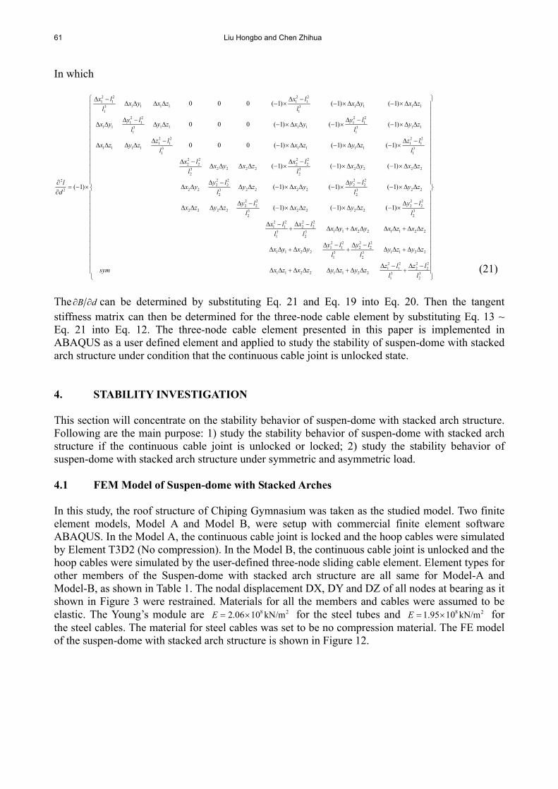
The B d can be determined by substituting Eq. 21 and Eq. 19 into Eq. 20. Then the tangent stiffness matrix can then be determined for the three-node cable element by substituting Eq. 13 ~ Eq. 21 into Eq. 12. The three-node cable element presented in this paper is implemented in ABAQUS as a user defined element and applied to study the stability of suspen-dome with stacked arch structure under condition that the continuous cable joint is unlocked state. 4. STABILITY INVESTIGATION This section will concentrate on the stability behavior of suspen-dome with stacked arch structure. Following are the main purpose: 1) study the stability behavior of suspen-dome with stacked arch structure if the continuous cable joint is unlocked or locked; 2) study the stability behavior of suspen-dome with stacked arch structure under symmetric and asymmetric load. 4.1 FEM Model of Suspen-dome with Stacked Arches In this study, the roof structure of Chiping Gymnasium was taken as the studied model. Two finite element models, Model A and Model B, were setup with commercial finite element software ABAQUS. In the Model A, the continuous cable joint is locked and the hoop cables were simulated by Element T3D2 (No compression). In the Model B, the continuous cable joint is unlocked and the hoop cables were simulated by the user-defined three-node sliding cable element. Element types for other members of the Suspen-dome with stacked arch structure are all same for Model-A and Model-B, as shown in Table 1. The nodal displacement DX, DY and DZ of all nodes at bearing as it shown in Figure 3 were restrained. Materials for all the members and cables were assumed to be elastic. The Young’s module are 8 22.06 10 kN/mE for the steel tubes and 8 21.95 10 kN/mE for the steel cables. The material for steel cables was set to be no compression material. The FE model of the suspen-dome with stacked arch structure is shown in Figure 12.
Influence of Cable Sliding on the Stability of Suspen-dome with Stacked Arches Structures 62
Figure 12. FEM Model of Suspen-dome with Stacked Arch Structure
Table 1. Element Type for Finite Element Models
Element type Members Model-A Model-B
Single-layer lattice dome
B33 (2-node 3-D cubic beam element)
Arch B33 (2-node 3-D cubic beam element) Strut T3D2 (2-node linear displacement 3-D truss element)
Radial cables T3D2 (No compression) Latitudinal cables Three-node sliding cable
element T3D2 (No compression)
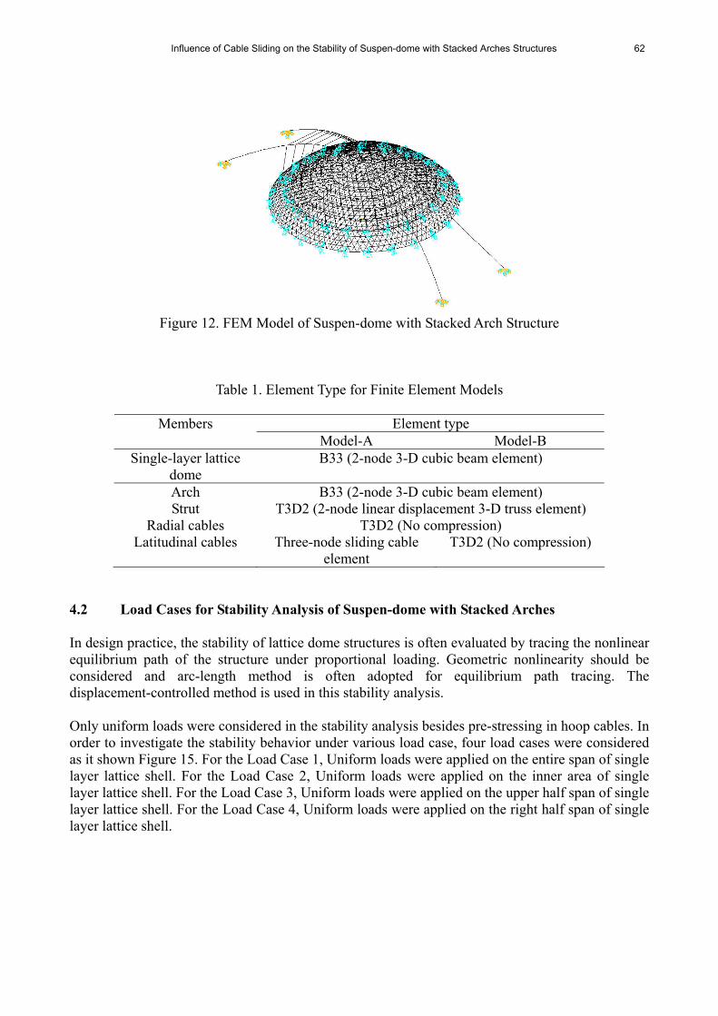
4.2 Load Cases for Stability Analysis of Suspen-dome with Stacked Arches In design practice, the stability of lattice dome structures is often evaluated by tracing the nonlinear equilibrium path of the structure under proportional loading. Geometric nonlinearity should be considered and arc-length method is often adopted for equilibrium path tracing. The displacement-controlled method is used in this stability analysis. Only uniform loads were considered in the stability analysis besides pre-stressing in hoop cables. In order to investigate the stability behavior under various load case, four load cases were considered as it shown Figure 15. For the Load Case 1, Uniform loads were applied on the entire span of single layer lattice shell. For the Load Case 2, Uniform loads were applied on the inner area of single layer lattice shell. For the Load Case 3, Uniform loads were applied on the upper half span of single layer lattice shell. For the Load Case 4, Uniform loads were applied on the right half span of single layer lattice shell.
63 Liu Hongbo and Chen Zhihua
(a) Load Case 1 (b) Load Case 2
(c) Load Case 3 (d) Load Case 4
Figure 13. Loading Conditions
4.3 Stability Analysis under Load Case 1 Figure 14 and Figure 15 shows that the instability modes for Model A and Model B under Load Case 1. Model A is firstly instable near the outmost rings. Model B is firstly instable near the center. Figure 16 shows that the typical load-displacement curves for Model A and Model B. From the Load-displacement curves, it can be concluded that the critical load of Model A with value of 13.78 kN/m2 is 5.6% higher than that of Model B with value of 13.05 kN/m2. Due to the existence of above arches, the nodal displacement and member stress is very uniform under uniform loading. For the Model A, because the continuous cable joint is locked, the adjacent members will share some displacement and member stress if local nodal displacement or member stress is extreme large. Therefore, the stability behavior of Model A is better than that of Model B under Load Case 1.

Influence of Cable Sliding on the Stability of Suspen-dome with Stacked Arches Structures 64
Figure 14. Instability shape of Model A under Load Case 1
Figure 15. Instability Shape of Model B under Load Case 1
0
2
4
6
8
10
12
14
16
-0.07 -0.05 -0.03 -0.01 0.01Displacement(m)
Loa
ds(k
N/m
^2)
modelA
modelB
Figure 16. Load-displacement Curves by Nonlinear Stability Analysis for Load Case 1
65 Liu Hongbo and Chen Zhihua
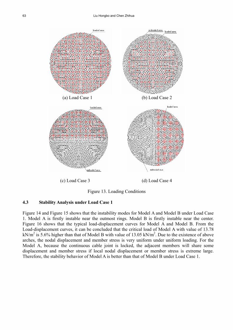
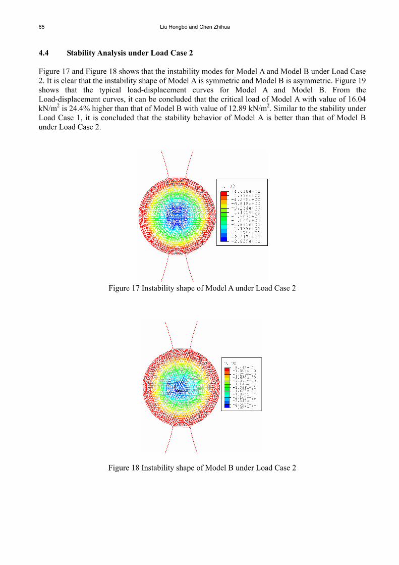
4.4 Stability Analysis under Load Case 2 Figure 17 and Figure 18 shows that the instability modes for Model A and Model B under Load Case 2. It is clear that the instability shape of Model A is symmetric and Model B is asymmetric. Figure 19 shows that the typical load-displacement curves for Model A and Model B. From the Load-displacement curves, it can be concluded that the critical load of Model A with value of 16.04 kN/m2 is 24.4% higher than that of Model B with value of 12.89 kN/m2. Similar to the stability under Load Case 1, it is concluded that the stability behavior of Model A is better than that of Model B under Load Case 2.
Figure 17 Instability shape of Model A under Load Case 2
Figure 18 Instability shape of Model B under Load Case 2

Influence of Cable Sliding on the Stability of Suspen-dome with Stacked Arches Structures 66
02468
1012141618
-0.15 -0.12 -0.09 -0.06 -0.03 0 0.03Displacement(m)
Loa
ds(k
N/m
^2)
modelA
modelB
Figure 19. Load-displacement Curves by Nonlinear Stability Analysis for Load Case 2
4.5 Stability analysis under Load Case 3 Figure 20 and Figure 21 shows that the instability modes for Model A and Model B under Load Case 3. It is clear that the instability area of Model A is larger than that of Model B. Figure 22 shows that the typical load-displacement curves for Model A and Model B. From the Load-displacement curves, it can be concluded that the critical load of Model A with value of 15.44 kN/m2 is 42.5% higher than that of Model B with value of 10.85 kN/m2. Similar to the stability under Load Case 1, it is concluded that the stability behavior of Model A is better than that of Model B under Load Case 3.
Figure 20. Instability Shape of Model A under Load Case 3

67 Liu Hongbo and Chen Zhihua
Figure 21. Instability Shape of Model B under Load Case 3
0
5
10
15
20
0 0.04 0.08 0.12 0.16 0.2
Displacement(m)
Loa
ds(k
N/m
^2)
ModelA
ModelB
Figure 22. Load-displacement Curves by Nonlinear Stability Analysis for Load Case 3
4.6 Stability analysis under Load Case 4 Figure 23 and Figure 24 shows that the instability modes for Model A and Model B under Load Case 4. It is clear that the instability area of Model A is larger than that of Model B. Figure 25 shows that the typical load-displacement curves for Model A and Model B. From the Load-displacement curves, it can be concluded that the critical load of Model A with value of 17.07 kN/m2 is 9.7% higher than that of Model B with value of 15.56 kN/m2. Similar to the stability under Load Case 1, it is concluded that the stability behavior of Model A is better than that of Model B under Load Case 4.

Influence of Cable Sliding on the Stability of Suspen-dome with Stacked Arches Structures 68
Figure 23. Instability Shape of Model A under Load Case 4
Figure 24. Instability Shape of Model B under Load Case 4
0
2
4
6
8
10
12
14
16
18
0.02 0.04 0.06 0.08 0.1 0.12
Displacement(m)
Loa
ds(k
N/m
^2)
ModelA
ModelB
Figure 25. Load-displacement Curves by Nonlinear Stability Analysis for Load Case 4
69 Liu Hongbo and Chen Zhihua
5. CONCLUSIONS A new structural system of suspen-dome with stacked arch structure is presented in this paper. In order to study the stability behavior of the suspen-dome with stacked arch structure under condition that the hoop cable can slide around cable joint, the tangent stiffness matrix of a three-node sliding cable element was derived. Then the three-node sliding cable element was implemented in commercial finite element software ABAQUS as a user defined element and applied in the stability analysis of a suspen-dome with stacked arch structure under both symmetric and asymmetric loads. The following conclusions were obtained from the stability analysis results: 1) the critical load when the continuous cable joint is locked is higher than that when the of continuous cable joint is unlocked; 2) if the continuous cable joint is locked, the adjacent members will share some displacement and member stress if local nodal displacement or member stress is extreme large; 3) if the continuous cable joint is unlocked, the adjacent members cannot share some displacement and member stress effectively if local nodal displacement or member stress is extreme large; 4) compared with the stability under condition that the continuous cable joint is unlocked, the stability behavior is better under condition that the continuous cable joint is locked. ACKNOWLEDGEMENTS This work is sponsored by the committee of national science foundation of china (Grant No: 50778122) and Program for New Century Excellent Talents in University of Ministry of Education in China (Grant No: NCET-06-0228) REFERENCES [1] Kawaguchi, M., Abe, M. and Tatemichi, I., “Design, Tests and Realization of ‘suspen-dome’
System, Journal of the IAAS, 1999, Vol. 40, No. 131, pp. 179-192. [2] Saitoh, M. and Okada, A., “The Role of String in Hybrid String Structure”, Engineering
Structures, 1999, Vol. 21, No. 8, pp. 280-284. [3] Kawaguchi, M., Tatemichi, I. and Chen, P.S., “Optimum Shapes of a Cable Dome
Structure”, Engineering Structures, 1999, Vol. 21, No. 8, pp. 719-725. [4] Chen, Z.H., Qiao, W.T. and Yan, X.Y., “Cable Supported Barrel Vault Structure System and
Research on Mechanics Feature”, Advanced Steel Construction, 2010, Vol. 6, No. 3, pp. 867-878.
[5] Zhou, Z., Meng, S.P. and Wu, J., “Pretension Process Analysis of Arch-supported Prestressed Grid Structures Based on Member Initial Deformation”, Advances in Structural Engineering, 2010, Vol. 13, No. 4, pp. 641-649.
[6] Kang, W.J., Chen, Z.H., Lam, H.F., et al., “Analysis and Design of the General and Outmost-ring Stiffed Suspen-dome Structures”, Engineering Structures, 2003, Vol. 25, pp. 1685-1695.
[7] Kitipornchai, S., Kang, W.J., Lam, H.F., et al., “Facters Affecting the Design and Construction of Lamella Suspendome Systemes”, Journal of Constructional Steel Research, 2005, Vol. 61, No. 6, pp. 764-785.

Influence of Cable Sliding on the Stability of Suspen-dome with Stacked Arches Structures 70
[8] Chen, Z.H. and Li, Y., “Parameter Analysis on Stability of a Suspendome”, International Journal of Space Structure, 2005, Vol. 20, No. 2, pp. 115-124.
[9] Cui, X.Q. and Guo, Y.L., “Influence of Gliding Cable Joint on Mechanical Behavior of Suspen-dome Structures”, International Journal of Space Structure, 2004, Vol. 19, No. 3, pp. 149-154
[10] Cao, Q.S. and Zhang, Z.H., “A Simplified Strategy for Force Finding Analysis of Suspendomes”, Engineering Structures, 2010, Vol. 32, No. 1, pp. 306-310.
[11] Zhang, Z.H., Cao, Q.S., Dong, S.L. and Fu, X.Y., “Structural Design of a Practical Suspendome”, Advanced Steel Construction, 2008, Vol. 4, No. 4, pp. 323-340.
[12] Zhang, A.L., Liu, X.C., Wang, D.M., et al., ”Static Experimental Study on the Model of the Suspend-dome of the Badminton Gymnasium for 2008 Olympic Games”, Journal of Building Structures, 2007, Vol. 28, No. 6, pp. 58-67.
[13] Wang, S., Zhang, G.J., Zhang, A.L., et al., ”The Prestress Loss Analysis of Cable-strut Joint of the Badminton Gymnasium for 2008 Olympic Games”, Journal of Building Structures, 2007, Vol. 28, No. 6, pp. 39-44.
[14] Chen, Z.H., Liu, H.B., Wang, X.D., Zhou, T., “Establishing and Application of Cable-Sliding Criterion Equation”, Advanced Steel Construction, 2011, Vol. 7, No. 2, pp. 131-143.
[15] Cui, X.Q. and Guo, Y.L., “Influence of Gliding Cable Joint on Mechanical Behavior of Suspend-dome Structures”, International Journal of Space Structures 2004, Vol. 19, No. 3, pp. 149-154.
[16] Zhang, G.F., Dong, S.L., et al., “Research on Sliding Cable in Construction of Suspend-dome Structures”, Journal of Zhejiang University (Engineering Science), 2008, Vol. 42, No. 6, pp. 1051-1057. [In Chinese]
[17] Zhou, B., Accorsi, M.L. and Leonard, J.W., “Finite Element Formulation for Modeling Sliding Cable Elements”, Computers & Structures, 2004, Vol. 82, No. 2-3, pp. 271-280.
[18] ABAQUS/Standard User’s Manual, Hibbitt, Karlsson & Sorensen Inc, Pawtucket (RI), 2002.