industrial 19 crt monitor - literature.rockwellautomation.com · industrial 19" crt monitor 5...
TRANSCRIPT

Industrial 19" CRT Monitor
(Bulletin 6157-C)
Installation and User Manual

2 Table of Contents
Publication 6157-UM001A-EN-P
77DDEOH REOH RII &RQWH&RQWHQQWVWVIndustrial 19" CRT Monitor .............................................. 3Description........................................................................... 3Package Contents ................................................................. 6Installation Guidelines.......................................................... 6Panel Mounting (6157-CE/ 6157-CF)................................... 8Rack Mounting (6157-CB)................................................... 14Connecting the 6157- C Industrial Monitor........................... 21Operating the 6157- C Industrial Monitor............................. 25Routine Maintenance............................................................ 39Troubleshooting ................................................................... 40Allen-Bradley Support......................................................... 42Appendix A: Touchscreen Serial Interface........................ 43Description........................................................................... 43Setting Up the Touchscreen Interface.................................... 43Performing a Calibration ...................................................... 45Appendix B: Video Cables................................................. 46HD-15 Connectors ............................................................... 46BNC Connectors .................................................................. 47Specifications...................................................................... 48
Important User Information Solid state equipment has operational characteristics differing from those ofelectromechanical equipment. "Safety Guidelines for the Application, Installation, andMaintenance of Solid State Controls" (Publication SGI-1.1) describes some importantdifferences between solid state equipment and hard-wired electromechanical devices.Because of this difference, and because of the wide variety of uses for solid stateequipment, all persons responsible for applying this equipment must satisfy themselvesthat each intended application of this equipment is acceptable.
In no event will Rockwell Automation be responsible or liable for indirect orconsequential damages resulting from the use or application of this equipment.
The examples and diagrams in this manual are included solely for illustrative purposes.Because of the many variables and requirements associated with any particularinstallation, Rockwell Automation cannot assume responsibility or liability for actualuse based on the examples and diagrams.
No patent liability is assumed by Rockwell Automation with respect to use of theinformation, circuits, equipment, or software described in this manual.
Reproduction of the contents of this manual, in whole or in part, without writtenpermission of Rockwell Automation is prohibited.
Throughout this manual, we use notes to make you aware of safety considerations.
ATTENTION: Identifies information about practices orcircumstances that can lead to personal injury or death,property damage, or economic loss.
Important: Identifies information that is especially important for successfulapplication and understanding of the product.

Industrial 19" CRT Monitor 3
Publication 6157-UM001A-EN-P
,QGXVWULDO,QGXVWULDO ���� &57 0RQLW�� &57 0RQLWRRUU
The 6157-C Industrial 19" CRT Monitor is a general-purpose monitorsuitable for a wide range of industrial computing applications. It offersthe following features:
• Panel and rack mount enclosures
• Pure flat screen
• Reliable and rugged industrial design
• Bright, crisp display
• Touchscreens
• Sync-on-green, separate sync, and composite sync video support
• On-screen display for easy setup
• Versatile multi-sync design (640x480 to 1600x1200 resolution)
Note: This monitor can display resolutions up to 1600x1200at 75 Hz. If you experience unexpected resultsoperating the monitor at this resolution, verify that themonitor is operating at 75 Hz or less.
ATTENTION: The equipment described in thisdocument generates, uses, and emits radio frequencyenergy. The equipment has been tested and found tocomply with FCC Rules, Part 15, subpart J, for Class Acomputing devices.
The use of non-shielded interface or power cords withAllen-Bradley industrial monitors is prohibited.
ATTENTION: X-ray emissions from these monitors aretypically about 0.05 mR/hr maximum, well below the0.5 mR/hr maximum recommended by the US.Department of Health and Human Resources andspecified in "Federal Performance Standards forTelevision Receivers", Section 10, Part 1020, Title 21, ofthe U. S. Code of Regulation (PL90-620), Vol. 38, No.198.
These monitors are equipped with X-ray protectioncircuits that cause automatic shutdown of the equipmentin case its X-ray emissions begin to approach federallimits.
Description
4 Industrial 19" CRT Monitor
Publication 6157-UM001A-EN-P
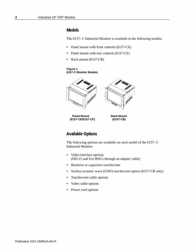
Models
The 6157- C Industrial Monitor is available in the following models:
• Panel mount with front controls (6157-CE)
• Panel mount with rear controls (6157-CF)
• Rack mount (6157-CB)
Figure 16157-C Monitor Models
Panel Mount Rack Mount (6157-CE/6157-CF) (6157-CB)
Available Options
The following options are available on each model of the 6157- CIndustrial Monitor:
• Video interface options(HD-15 and five BNCs through an adapter cable)
• Resistive or capacitive touchscreen
• Surface acoustic wave (SAW) touchscreen option (6157-CB only)
• Touchscreen cable options
• Video cable options
• Power cord options

Industrial 19" CRT Monitor 5
Publication 6157-UM001A-EN-P
Part Numbers
The part number for your particular unit consists of the model number(6157) followed by a nine-digit code indicating the options on your unit.
Example:
6157 - CE D A A Z A A Z Z
1 2 3 4 5 6 7 8 9 10
Following are explanations of the part numbers for the various models ofthe 6157-C units.
Table ACatalog Number Explanation for 6157- C Industrial Monitors
Position Option OptionLetter
Category Description
CB Rack Mount, NEMA 1, 9U, Front Controls
CE Panel Mount, NEMA 4/4X, 9U, Front Controls
2 Display/Enclosure
CF Panel Mount, NEMA 4/4X, 9U, Rear Controls
B Resistive Antiglare Touchscreen
D Capacitive Antiglare Touchscreen
G SAW Polished Touchscreen (Rack Mount Only)
W Tempered Glass Anti-reflective Display Shield
3 Touchscreen/Display Shield
Z None (No Display Shield)
4 Video Interface A HD-15
A 120/240 VAC, USA Power Cord5 Power Input/Line Cord B 120/240 VAC, No Power Cord
6 Future Options Z None
A 6 ft (1.8 m) HD-15 - HD-15 Cable
B 15 ft (4.6 m) HD-15 - HD-15 Cable
7 External VideoCable
K 1ft (0.3 m) 5-BNC - HD-15 Cable
A 6 ft (1.8 m) DE9 - DE9 Cable
B 15 ft (4.6 m) DE9 - DE9 Cable
8 TouchscreenCable
Z None
9 Future Options Z None
B 18" Rack Mount Slides (Pair)
C 24" Rack Mount Slides (Pair)
D 18" Rack Mount Slides (Pair), EIA 19" 1U AdapterPanel
E 24" Rack Mount Slides (Pair), EIA 19" 1U AdapterPanel
10 EnclosureAccessories
Z None
Note: Not all options are available with all models.
6 Industrial 19" CRT Monitor
Publication 6157-UM001A-EN-P
Before unpacking a new monitor, inspect the shipping carton for damage.If damage is visible, immediately contact the shipper and requestassistance. Otherwise, proceed with unpacking.
Note: Make sure you keep the original packaging for the monitorin case you need to return the monitor for repair.
The monitor shipping carton contains the following items:
• Monitor
• Package of mounting hardware
• AC power cord (optional)
• Video cable (optional)
• Enclosure accessories (i.e. rack sides for rack mount only) (optional)
• This user manual
An 6157- C Industrial Monitor with a touchscreen option is shipped withthese additional items:
• Supporting software and manuals
• RS-232 serial extension cable (optional)
When installing the unit, it is important to consider environmentalfactors at the site that could affect performance as well as possibleeffects from equipment operation on personnel and nearby equipment.
Note: Remember that heat rises—many times the temperature atthe top of an enclosure is much higher than the rest of theenclosure if the air is not circulating. Without activecooling or an internal fan, the temperature at the top of anenclosure can be 10° - 20°C hotter than at the middle orbottom of the enclosure.
Important: This monitor is designed to operate at a range of extremes,however it is not good design practice to continuouslyoperate the monitor at the highest end of the specifiedtemperature range.While the product will operate at its highest specifiedtemperature, the overall life span of any electronic device isshortened when it operates at its highest rated temperature.
Package Contents
Installation Guidelines

Industrial 19" CRT Monitor 7
Publication 6157-UM001A-EN-P
Following the guidelines below will help ensure that the monitor willprovide safe and reliable service.
• Ensure that sufficient power is available from a single phase ACoutlet at the site.
• Ensure that sufficient space is available around air inlets and outletsto provide the circulation necessary for cooling. Never allow airpassages to become obstructed. The monitor is equipped with a fanto ensure proper cooling.
• Dust and smoke particles can cause problems, since they can collectat ventilating holes in the enclosure and interfere with cooling.Accordingly, where dust and smoke are problems it is especiallyimportant to keep air vents clean. Refer to the Routine Maintenancesection (Page 39) for more information.
• Ensure that the ambient air temperature will not exceed thespecified maximum temperature. A user supplied fan, heat exchanger,or air conditioner may be required to meet this condition in someinstallations.
• Leave the monitor’s enclosure or cover in place at all times duringoperation. The cover affords protection against high voltages insidethe monitor and inhibits radio-frequency emissions that mightinterfere with other equipment.
• The Federal Communications Commission has prepared a pamphletthat addresses the problem of radio frequency interference to radioand television reception, which should be consulted in case ofproblems with such interference. This publication, “How to Identifyand Resolve Radio/TV Interference Problems” (Stock #004-000-00345-4) may be obtained from the US. Government Printing Office,Washington, DC 20402.
• Determine the minimum and maximum ambient humidity for themonitor by consulting the specification sheets at the back of thismanual. Ensure that the humidity of the ambient air will not exceedthese limits. In very dry environments, static charges build up veryreadily. Proper grounding of the equipment through the AC powercord can help reduce the likelihood of static discharges, which maycause shocks and damage electronic components.

8 Industrial 19" CRT Monitor
Publication 6157-UM001A-EN-P
When properly installed, the panel mount version of the 6157- CIndustrial Monitor is designed to provide protection against water anddust to NEMA 4 and 4X (IP 65 equivalent) and NEMA 12 (IP 52equivalent) standards.
No slides or shelves are required because the 6157- C Industrial Monitoris designed to be supported by the panels in which it is installed.
Figure 2Generic Panel Mount Diagram
Tools Needed
In addition to the tools required to make the cutout, you will need thefollowing tools to mount the monitor:
• 3/8 in. deep well socket
• ¼ in. drive extension – 12 in. or longer
• ¼ in. drive ratchet or ¼ in. drive torque ratchet
Panel Mounting (6157-CE/6157-CF)

Industrial 19" CRT Monitor 9
Publication 6157-UM001A-EN-P
Panel Mounting Guidelines
Observe the following precautions before installing the unit in a panel:
• Confirm that there is adequate space behind the panel. Remember toallow extra space for air circulation and cabling. Allow 63.5 mm(2.5 in) behind and 50.8 mm (2 in) above, below, and on each side forair circulation and cabling.
• Confirm that the cabinet is deep enough to accommodate themonitor's depth while providing rear clearance for airflow. A cabinetwith depth of 523.7 mm (20.62 in.) is sufficient.
• Take precautions so that metal cuttings do not enter any componentsthat are already installed in the panel.
• Supporting panels should be at least 14 gauge to ensure propersealing against water and dust and to provide proper support. Themounting hardware supplied accommodates panels up to 6.4 mm(0.25 in) thick.
Note: Supporting panels must be cut and drilled tospecifications prior to installation.
ATTENTION: Failure to follow these warnings mayresult in personal injury or damage to the panelcomponents.

10 Industrial 19" CRT Monitor
Publication 6157-UM001A-EN-P
Mounting the 6157-CE/6157-CF in a Rack
Due to the front panel size and stud pattern, the panel mount versions ofthe 6157- C Industrial Monitor can be installed in an EIA 19 in. 9U panelstandard rack. Refer to the following figure:
Figure 3Generic Rack Mounting Diagram
Important: If you install the panel mount versions of the 6157- CIndustrial Monitor in a rack, you must ensure that the rackcan support the weight of the monitor. You may need toinstall a support or shelf under the rear of the monitor tosupport the weight.

Industrial 19" CRT Monitor 11
Publication 6157-UM001A-EN-P
Panel Mount Dimensions (6157-CE/6157-CF)
This section provides diagrams you need to follow to install the unit.Dimensions are supplied in mm [in.]
Figure 46157-CE/6157-CF Industrial Monitor Dimensions

12 Industrial 19" CRT Monitor
Publication 6157-UM001A-EN-P
Panel Mounting Procedure
1. Confirm that the shipping carton contains a package of 10-32 locknuts and flat washers. You will need 18 nuts and washers forinstallation. Extra lock nuts and washers are provided.
2. Refer to the physical dimension drawing (Figure 4) and confirm thatthere is adequate space behind the panel. Remember to allow extraspace for circulation and cabling.
3. Refer to the panel cutout drawing below for dimensions of the panelcutout and mounting hole locations. Cut and drill the panel.
Note: Use #10-32 or M5 self-locking nuts for mounting.
Figure 5Panel Mounting Cutout

Industrial 19" CRT Monitor 13
Publication 6157-UM001A-EN-P
4. Carefully remove the monitor from its packaging. Avoid damagingthe monitor gasket.
Tip: It will be easier to install the monitor if you support it with a shelfor other support adjusted to the appropriate height.
5. Insert the monitor in the panel cutout from the front. Do not damagethe threaded mounting studs as you position the monitor.
6. Secure the unit with the lock nuts and washers provided. Tightenevenly to 24 inch-pounds of torque.
Important: To ensure a proper seal, be sure to install a washer andnut on each of the 18 mounting studs.
ATTENTION: Mounting nuts must be tightened to atorque of 24 inch-pounds to provide panel seal andavoid potential damage. Rockwell Automationassumes no responsibility for water or chemicaldamage to the monitor or other equipment within theenclosure due to improper installation.
7. Remove the protective adhesive sheet from the screen of theIndustrial Monitor. The sheet is designed to prevent scratching ofthe polycarbonate screen protector or the optional touchscreenduring shipping and installation. It should be removed before use.
14 Industrial 19" CRT Monitor
Publication 6157-UM001A-EN-P
When properly installed, the 6157-CB industrial monitor is designed toprovide protection to NEMA 1 (IP 10 equivalent) standards.
The rack mounting versions of the 6157- C Industrial Monitor aredesigned for installation in a rack enclosure that conforms to EIAstandards for equipment with 19" (483 mm) wide rails.
Note: Retainer screws prevent the unit from being pulled out onits slides accidentally; they are not intended to support theweight of the unit.
Tools Needed
You will need the following tools and hardware:
• EIA panel mounting hardware
• Chassis slides or shelf
• Screwdriver
Rack Mounting Guidelines
Observe the following precautions when installing this unit in a rack:
• The cabinet must be tall enough to accommodate the monitor's panelheight of 9 rack units, 15.75 in. (400 mm), and deep enough toaccommodate the monitor's depth while providing rear clearance forcabling and air flow. A cabinet with depth of 24 in. (610 mm) issufficient. A minimum clearance of 4 in. (102 mm) from the topinside edge of the rack is required for airflow.
• The monitor is designed to be supported in the cabinet by telescopingslides. Slide mounting points are provided on the lower sides of themonitor chassis. These mounting points are designed to accommodateGeneral Devices Co. Chassis-Trak® Model C-300-S or equivalentslides. Slides of this kind are available from Rockwell Automation in18 in. and 24 in. lengths, with or without 6 in. extenders.
Rack Mounting (6157-CB)

Industrial 19" CRT Monitor 15
Publication 6157-UM001A-EN-P
Note: The mounting rails that run vertically along the insideedges of the front and rear openings of EIA rackcabinets can be of two types:
• “Wide” rails have holes spaced 0.5 in. (12.7mm)and 1.25 in. (31.8mm) on centers, in a repeatingpattern. These rails are prevalent in Europe.
• “Universal” rails have holes spaced 0.5 in.(12.7mm), 0.625 in. (15.9mm), and 0.625 in.(15.9mm) on centers, in a repeating pattern. Thus,the “universal” rails have a hole pattern thatcontains the “wide” pattern but provides anadditional hole at the midpoint of the pattern.“Universal” rails are most prevalent in the US.
ATTENTION: Failure to follow these warnings mayresult in personal injury or damage to the panelcomponents.
16 Industrial 19" CRT Monitor
Publication 6157-UM001A-EN-P
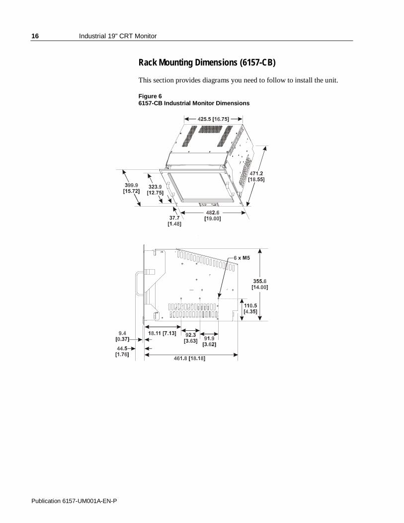
Rack Mounting Dimensions (6157-CB)
This section provides diagrams you need to follow to install the unit.
Figure 66157-CB Industrial Monitor Dimensions

Industrial 19" CRT Monitor 17
Publication 6157-UM001A-EN-P
Rack Mounting Procedure
Step 1 - Locate the mounting areas:
You must allocate the required space in your enclosure for the monitor.The monitor’s panel height is 9 rack units (15.75 in. or 400 mm) and youmust determine if panel spacers are required above or below the monitor.
Locate the following areas to mount the slides:
• Locate the points at which the bottom edge of the monitor front panelwill intersect the cabinet front mounting rails. The four slots in themonitor front panel should be aligned with holes in the frontmounting rails.
• Locate points on the front rails 5.25 in. (133 mm) above the points ofwhere the bottom edge of the monitor panel intersects the rail. Thesepoints indicate the center line of each slide.
• Locate points on the rear rails equal in height to the slide center linepoints on the front rails.
Figure 7Mounting Areas on a Rack
18 Industrial 19" CRT Monitor
Publication 6157-UM001A-EN-P
Note: Clearance between the inside edges of the frontmounting rails is nominally 17.75 in. (451 mm) forstandard cabinets.This clearance can vary somewhat and might or mightnot be adjustable. Ensure that the clearance is at least17.65 in. (448 mm) for standard monitors and at least17.73 in. (450 mm) for monitors with magnetic shieldsoption installed.
Note: Magnetic shields are secured with nylon rivets insertedthrough their sides. The rivet heads require clearancegreater than 17.73 in. (450 mm). If this additionalclearance is not available, the rivets must be removedbefore the monitor is installed in the cabinet.
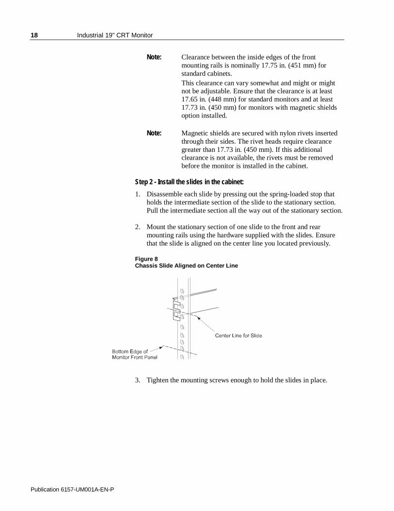
Step 2 - Install the slides in the cabinet:
1. Disassemble each slide by pressing out the spring-loaded stop thatholds the intermediate section of the slide to the stationary section.Pull the intermediate section all the way out of the stationary section.
2. Mount the stationary section of one slide to the front and rearmounting rails using the hardware supplied with the slides. Ensurethat the slide is aligned on the center line you located previously.
Figure 8Chassis Slide Aligned on Center Line
3. Tighten the mounting screws enough to hold the slides in place.

Industrial 19" CRT Monitor 19
Publication 6157-UM001A-EN-P
4. Repeat these steps to mount the stationary section of the other slideto the front and rear mounting rails on the opposite side.
5. Measure the space between the inside edges of the stationary slidesto determine the clearance. Adjust the spacing to 16.8 in. (427 mm
6. Fully tighten the mounting screws holding the stationary sections tothe front and rear mounting rails of the cabinet.
7. Locate the holes in the front mounting rails corresponding to themonitor’s front panel mounting holes. Install clip nuts behind theholes in the rails if the holes are not threaded.
Step 3 - Mount the slides on the monitor:
1. Take up the sections of the slides previously removed from thestationary sections. Pull the interior sections out of the intermediatesections far enough to gain access to the mounting holes in theinterior sections.
2. Align the interior section’s mounting holes with corresponding holeson the brace of the monitor chassis. Attach the interior section of theslide to the side of the chassis with hardware supplied. Tightenscrews securely.
3. Repeat these steps to attach the interior section of the other slide tothe opposite side of the chassis.
Step 4 - Install the monitor in the cabinet:
1. Position the monitor chassis, with slide extensions installed, in frontof the prepared cabinet.
2. Lift the monitor chassis to the height required to align theintermediate sections of the slides (attached to the chassis) with thecorresponding stationary sections (attached to the cabinet rails).
ATTENTION: To avoid danger of personal injury oraccidental damage to equipment, it is recommendedthe monitor be lifted by two persons, both wearingback braces.
3. Push the intermediate sections of the slides into the stationarysections until the retaining locks are engaged.
4. If the monitor will be accessible from the rear after installation,cabling may be installed from the rear at a later time. Otherwise,power and video cabling should be installed at this time, while themonitor is supported by the slides in extended position.

20 Industrial 19" CRT Monitor
Publication 6157-UM001A-EN-P
5. Slide the chassis into the cabinet. Secure the monitor chassis to thecabinet by installing screws through the four holes in the monitorfront panel in such a way that they engage the threaded holes on theclip nuts installed previously behind corresponding holes in the rails.
Note: Retainer screws prevent the unit from being pulled outon its slides accidentally; they are not intended tosupport the weight of the unit.
6. Remove the protective adhesive sheet from the screen of theIndustrial Monitor. The sheet is designed to prevent scratching ofthe polycarbonate screen protector or the optional touchscreenduring shipping and installation. It should be removed before use.

Industrial 19" CRT Monitor 21
Publication 6157-UM001A-EN-P
The rear panel of the 6157- C Industrial Monitor has connectors forattaching cables to accomplish the following:
• Connecting to a host video source(HD-15 VGA or optional HD-15 to BNC adapter)
• Connecting to a host touchscreen control port (DE-9 connector)(optional)
• Connecting to AC power
Note: Some connectors on your monitor may differ from thefollowing figure.
The following figure illustrates the standard configuration for the 6157-C Industrial Monitor.
Figure 9Rear Panel
Connecting the 6157- CIndustrial Monitor

22 Industrial 19" CRT Monitor
Publication 6157-UM001A-EN-P
Connecting the Video Source
The video connection to the host is made through a HD-15 (female)connector or to BNC connectors using a 5-BNC to HD-15 adapter cable.For more information on using an HD-15 video cable to connect to thehost computer, refer to Appendix B (Page 46).
To establish a signal using the HD-15 connector:
1. Obtain a shielded, properly terminated video cable of length as shortas possible. Longer cables (up to approximately 50 feet in somecases) may be used, provided they are properly constructed. Yourpackage may include a 6- or 15-foot video cable, if specified.
2. Connect one end of the cable to the female HD-15 video inputconnector on the rear panel of the monitor.
3. Connect the other end to the output of any IBM-compatible VGAadapter or other video generator.
Note: It may be possible to connect the monitor to videogenerators that do not conform to VGA standards. Themain requirement is that the generator provide analogRGB video signals (0.714V or 1V above referenceblack into 75 ohms) and separate horizontal and verticalsync signals. Please contact your Rockwell Automationrepresentative for more information,
To establish a signal using the BNC to HD-15 BNC adapter cable:
1. Obtain 75-ohm coaxial cables fitted with BNC connectors. Makesure the cables are of equal length.
Note: A BNC to HD-15 adapter cable is available fromRockwell Automation for connecting the monitor to aBNC terminated RGB video source.
2. Connect one end of the cable to the appropriate BNC inputconnectors (R, G, B, HS/CS, VS) on the video source.
Note: The BNC cables are color coordinated for the red,green, and blue connectors. The horizontal and verticalsync connectors are typically gray and black. Theletters H (horizontal sync) and V (vertical sync) areembossed on the plastic covering of the appropriateconnectors.
3. Connect the other end to the corresponding connector of the BNC toHD-15 adapter cable.

Industrial 19" CRT Monitor 23
Publication 6157-UM001A-EN-P
4. Connect the adapter to the HD-15 video connector on the rear panelof the monitor.
Connecting the Touchscreen Interface
The serial touchscreen interface connection to the host is made throughan RS-232 DE-9 (female) connector located on the rear panel.
The optional touchscreen provides a high-resolution touch input system.Driver software included with the package allows the touchscreen tofunction with many popular DOS and Windows®-based industrialapplications as a pointing device (mouse).
Note: Refer to the manual included with the touchscreen optionand Appendix A of this manual (page 43) for additionaldetails on the installation and operation of the touchscreen.
To connect the touchscreen:
1. For units with the touchscreen option, make sure you have one of theoptional serial cables.
2. Connect one end of the touchscreen serial cable to the T/S portconnector on the rear of the monitor.
3. Connect the other end to any serial communications port on the hostcomputer.
4. Tighten the captive screws on the cable connector to secure it.

24 Industrial 19" CRT Monitor
Publication 6157-UM001A-EN-P
Connecting AC Power
The 6157- C Industrial Monitor requires a single-phase power supplyproviding 100-130 or 198-264 VAC at 50-60 Hz. Power must beavailable at a grounded three-pin outlet located nearby. Wheneverpossible, connect the monitor to the same AC source that supplies thecomputer.
To connect AC power to the monitor:
1. Turn off the main switch or breaker.
2. Use the ground terminal of the monitor to establish a chassis-to-earthground connection. Secure one end of a ground strap to the groundterminal. Connect the other end of the ground strap to a good earthground.
The ground terminal is an M5 screw.
ATTENTION: Chassis ground must be connected forsafe operation of the monitor. The AC receptacle on themonitor is a 3-wire type with chassis ground pin, and themating AC cord supplied is a 3-wire type, designed forconnection to a grounded 3-pin AC outlet. However, aproperly ground AC outlet is not always available, andgrounding using a 3-wire cord can easily be defeated. Ifyou fail to ground the monitor properly, the setup mayresult in personal injury from electrical shock or damageto the equipment.
3. Connect the socket end of the AC power cord to the matingconnector on the rear panel of the monitor.
4. Connect the plug end of the AC power cord to the main outlet.
5. Restore AC power to the outlet.
Industrial 19" CRT Monitor 25
Publication 6157-UM001A-EN-P
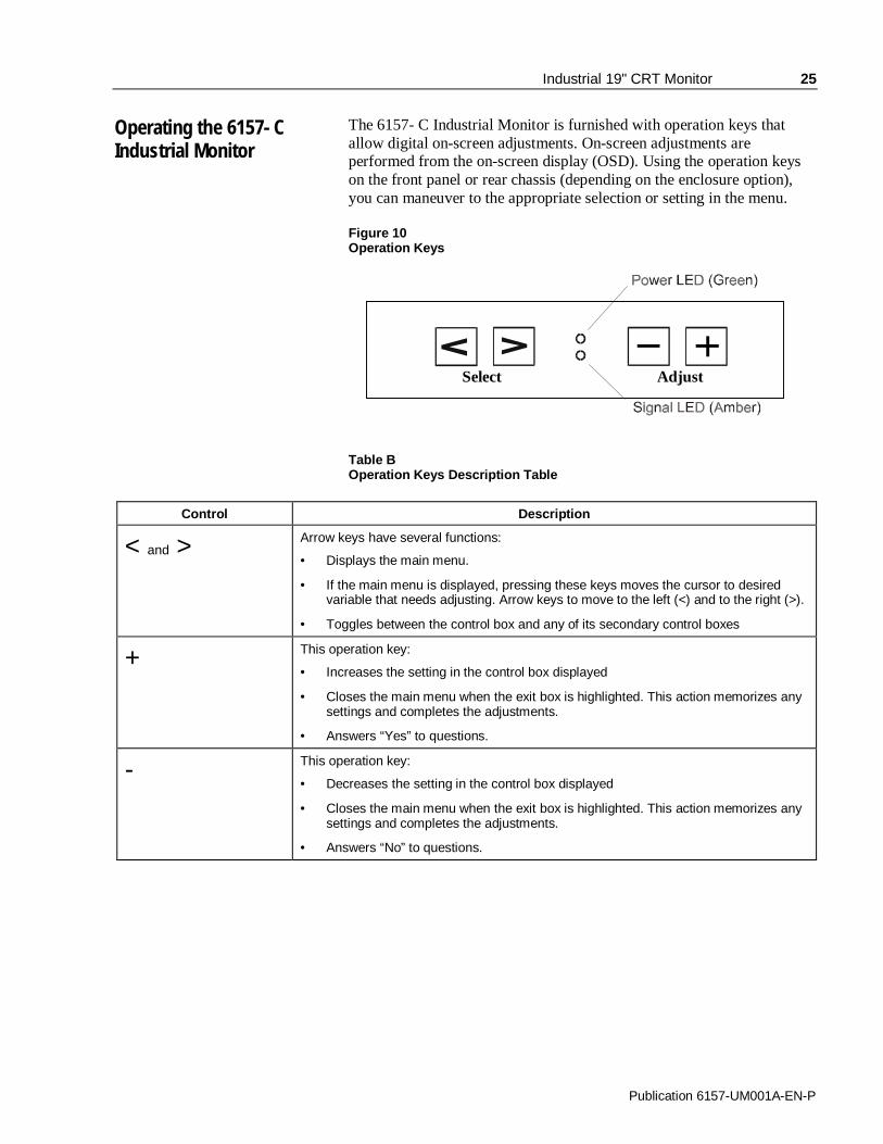
The 6157- C Industrial Monitor is furnished with operation keys thatallow digital on-screen adjustments. On-screen adjustments areperformed from the on-screen display (OSD). Using the operation keyson the front panel or rear chassis (depending on the enclosure option),you can maneuver to the appropriate selection or setting in the menu.
Figure 10Operation Keys
Select Adjust
Table BOperation Keys Description Table
Control Description
< and > Arrow keys have several functions:
• Displays the main menu.
• If the main menu is displayed, pressing these keys moves the cursor to desiredvariable that needs adjusting. Arrow keys to move to the left (<) and to the right (>).
• Toggles between the control box and any of its secondary control boxes
+ This operation key:
• Increases the setting in the control box displayed
• Closes the main menu when the exit box is highlighted. This action memorizes anysettings and completes the adjustments.
• Answers “Yes” to questions.
- This operation key:
• Decreases the setting in the control box displayed
• Closes the main menu when the exit box is highlighted. This action memorizes anysettings and completes the adjustments.
• Answers “No” to questions.
Operating the 6157- CIndustrial Monitor

26 Industrial 19" CRT Monitor
Publication 6157-UM001A-EN-P
Status LEDs
The 6157- C Industrial Monitor has two status LED indicators on thekeypad. The following table lists the functions assigned to the LEDs:
Table C6157- C Industrial Monitor Status LED Indicators
LED Description
Power LED (Green) Indicates that power is applied to the monitor.
Status LED (Amber) Indicates that the monitor is not receiving a videosignal.
Note: For information on troubleshooting the 6157- C IndustrialMonitor, refer to Page 40.
Auto Degauss
Degauss is automatically activated when the display has been poweredoff for at least 20 minutes and power is applied.
Auto Registration
If adjustments have been made, the new settings are saved after tenseconds of inactivity when the display automatically closes the windows.

Industrial 19" CRT Monitor 27
Publication 6157-UM001A-EN-P
Self-Test Display
When there is no signal input (no connection), the OSD shows thefollowing:
Figure 11Self-Test Display
9300K 6500K 5500K
When the synchronization signal is out of specification, the OSD willshow current horizontal and vertical frequency on red image, thendisappear. For example:
106Khz /85 .0Hz

28 Industrial 19" CRT Monitor
Publication 6157-UM001A-EN-P
Adjusting the On-Screen Display (OSD)
This section explains the on-screen display and explains how to makeoperation adjustments.
To display the main menu:
Press > or < to display the menu. The on-screen display appears on thescreen.
Figure 12On-Screen Display
You can make all the necessary adjustments by making selections in theon-screen display using one or all of the operation keys. The followingtable describes the controls on the on-screen display.
Table DOn-Screen Display Definitions
Symbol Control Action
Brightness Increases or decreases the intensity(illumination) of the image.
Contrast Increases or decreases the strength(lightness or dimness) of the image.
HorizontalSizing
Increases or decreases the size of the imagehorizontally.
HorizontalPosition
Moves images horizontally on screen left (-)or right (+).
Vertical Sizing Increases or decreases the size of the imagevertically.
VerticalPosition
Moves images horizontally on screen up (+)or down (-).
Pincushion Adjusts the side pincushion (or barreling)
Pinbalance Adjusts the curvature of the left and rightsides of the screen image.

Industrial 19" CRT Monitor 29
Publication 6157-UM001A-EN-P
Symbol Control Action
Parallel Corrects the image shape to a rectangle.
Trapezoid Corrects the image shape to a rectangle.
Rotation Corrects the screen tilt. For example, adjuststhe screen image to be horizontally level.
Reduces the optical effect of wavy lines onthe display image.
Color Adjusts the color temperature or whitebalance of the image.
Recall Resets the display settings to their originalfactory values.
Degauss Demagnetizes the CRTs metal frame forimproved image clarity.
Exit Select Exit to close the on-screen displaymain window.
Before advancing to these adjustments, you need to understand the basicfunctions of the operation keys. To aid in this understanding, a sampleprocedure is provided below:
Sample Procedure
1. Display the on-screen display (OSD) window by pressing > or <.
2. Press > or < to highlight the variable you want to adjust. Refer toTable B.
3. Press + or – to adjust the variable.
4. Repeat steps 2-3 for any variables you need to adjust.
5. Press > or <to select the exit icon from the OSD.
6. Press + or – to exit the OSD.
Note: If you do nothing for ten seconds, the display willautomatically close the window, memorize the settings andcomplete the adjustments.

30 Industrial 19" CRT Monitor
Publication 6157-UM001A-EN-P
Brightness Control
Use the brightness control to adjust the overall intensity of the display.After allowing the CRT to warm up for at least a minute, adjust for theleast amount of brightness needed to make the display clearly viewable.
Adjust the brightness to match the brightness level in the room so thatthe level will be easy to see.
1. Display the OSD.
2. Use the arrow keys (> or <) to select the brightness adjustment box.
3. Adjust the brightness value to its lowest setting. (For example, blackbackground with no text).
4. Adjust the brightness until black changes to dark gray.
5. Adjust the brightness down until the bar changes back to black. Thisis the optimal brightness setting given the current lightingconditions.
Note: Pressing the arrow keys simultaneously while thebrightness adjustment box is displayed sets the standardlevel.
6. Proceed to make other adjustments as necessary.
Note: If you wait ten seconds, the display will automatically closethe window, memorize the settings and complete theadjustments.

Industrial 19" CRT Monitor 31
Publication 6157-UM001A-EN-P
Contrast Control
Use the contrast control to adjust the difference between the monitor’slight and dark elements. With a suitable image displayed on the screen,adjust the contrast control to achieve the best balance between imagebrightness and fine detail rendition.
1. Display the OSD.
2. Use the arrow keys (> or <) to select the contrast adjustment box.
Note: Pressing the arrow keys simultaneously while thecontrast adjustment box is displayed sets the standardlevel.
3. Press + or – to adjust the contrast value given the current lightingconditions.
4. Proceed to make other adjustments as necessary.
Note: If you wait ten seconds, the display will automatically closethe window, memorize the settings and complete theadjustments.
Horizontal Position
Use the horizontal position controls to center the image horizontally onthe screen.
1. Display the OSD.
2. Use the arrow keys (> or <) to select the horizontal position box.
3. Press + or – to move the image to the left or right until it is centeredon your screen.
Note: You can use the arrow keys (> or <) to toggle betweenthe horizontal size and horizontal position controlboxes.
4. Proceed to make other adjustments as necessary.
Note: If you wait ten seconds, the display will automatically closethe window, memorize the settings and complete theadjustments.

32 Industrial 19" CRT Monitor
Publication 6157-UM001A-EN-P
Horizontal Size
Use the horizontal size controls to makes the image wider or narrower.
Note: Before adjusting the horizontal size, you must first centerthe image in the screen using the horizontal positioncontrols.
Pressing > toggles between the horizontal size andhorizontal position control boxes.
1. Display the OSD.
2. Use the arrow keys (> or <) to select the horizontal size box.
3. Press + or – narrow or widen the image on your screen.
4. Proceed to make other adjustments as necessary.
Note: If you wait ten seconds, the display will automatically closethe window, memorize the settings and complete theadjustments.
Vertical Position
Use the vertical position controls to center the image vertically on thescreen.
Note:Pressing > toggles between the vertical size and verticalposition control boxes.
1. Display the OSD.
2. Use the arrow keys (> or <) to select the vertical position box.
3. Press + or – to move the image up or down until it is centered on thescreen.
4. Proceed to make other adjustments as necessary.
Note: If you wait ten seconds, the display will automatically closethe window, memorize the settings and complete theadjustments.
Industrial 19" CRT Monitor 33
Publication 6157-UM001A-EN-P
Vertical Size
Use the vertical size controls to make the image taller or shorter.
Note: Before adjusting the vertical size, first center the image inthe screen.
1. Display the OSD.
2. Use the arrow keys (> or <) to select the vertical size box.
3. Press + or – key heighten or shorten the image on the screen.
4. Proceed to make other adjustments as necessary.
Note: If you wait ten seconds, the display will automatically closethe window, memorize the settings and complete theadjustments.
Vertical Pincushion
Use the vertical pincushion controls to correct the image for barrel orpincushion distortion.
1. Display the OSD.
2. Use the arrow keys (> or <) to select the vertical pincushion box.
3. Press the + or – key to straighten the sides of the screen image.
4. Proceed to make other adjustments as necessary.
Note: If you wait ten seconds, the display will automatically closethe window, memorize the settings and complete theadjustments.

34 Industrial 19" CRT Monitor
Publication 6157-UM001A-EN-P
Trapezoid
Use the trapezoid controls to correct trapezoidal distortion of the image.
1. Display the OSD.
2. Use the arrow keys (> or <) to select the trapezoid box.
3. Press + or – to make the image wider or narrower at the top of thescreen.
4. Proceed to make other adjustments as necessary.
Note: If you wait ten seconds, the display will automatically closethe window, memorize the settings and complete theadjustments.
Pinbalance
Use the pinbalance controls to adjust the curvature of the left and rightsides of the screen image.
1. Display the OSD.
2. Use the arrow keys (> or <) to select the pinbalance box.
3. Press + or – key to adjust the curvature at the left and right sides ofthe image until the sides of the image are straight.
4. Proceed to make other adjustments as necessary.
Note: If you wait ten seconds, the display will automatically closethe window, memorize the settings and complete theadjustments.

Industrial 19" CRT Monitor 35
Publication 6157-UM001A-EN-P
Parallelogram
Use the parallelogram controls to correct parallelogram distortion of theimage on the screen.
1. Display the OSD.
2. Use the arrow keys (> or <) to select the parallelogram box.
3. Press the + or – key to skew the image to the left or right.
4. Proceed to make other adjustments as necessary.
Note: If you wait ten seconds, the display will automatically closethe window, memorize the settings and complete theadjustments.
Rotation
Use the rotation controls to adjust for tilt of the image on the screen.
1. Display the OSD.
2. Use the arrow keys (> or <) to select the rotation box.
3. Press the + or – key to adjust the tilt of the image on the screen.
4. Proceed to make other adjustments as necessary.
Note: If you wait ten seconds, the display will automatically closethe window, memorize the settings and complete theadjustments.
36 Industrial 19" CRT Monitor
Publication 6157-UM001A-EN-P
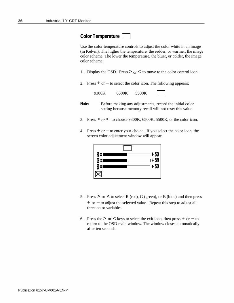
Color Temperature
Use the color temperature controls to adjust the color white in an image(in Kelvin). The higher the temperature, the redder, or warmer, the imagecolor scheme. The lower the temperature, the bluer, or colder, the imagecolor scheme.
1. Display the OSD. Press > or < to move to the color control icon.
2. Press + or – to select the color icon. The following appears:
9300K 6500K 5500K
Note: Before making any adjustments, record the initial colorsetting because memory recall will not reset this value.
3. Press > or < to choose 9300K, 6500K, 5500K, or the color icon.
4. Press + or – to enter your choice. If you select the color icon, thescreen color adjustment window will appear.
5. Press > or < to select R (red), G (green), or B (blue) and then press
+ or – to adjust the selected value. Repeat this step to adjust allthree color variables.
6. Press the > or < keys to select the exit icon, then press + or – toreturn to the OSD main window. The window closes automaticallyafter ten seconds.
Industrial 19" CRT Monitor 37
Publication 6157-UM001A-EN-P
Recall
Use this option to reset the display settings to their original factoryvalues.
1. Display the OSD.
2. Use the arrow keys (> or <) to select the recall box.
3. Press the + or – key to reset the display values to their originalfactory settings.
Degauss
The display screen is degaussed automatically each time the monitor ispowered on. This degaussing eliminates color impurities and otherdistortions of the display by neutralizing the effects of magnetic fields inthe surrounding environment.
When the unit is left on for a long period, or is repositioned followingpower-up, the screen may pick up additional magnetic flux, causingcolors to appear "blotchy" or otherwise distorted. For full effectiveness,allow at least 20 minutes between manual degaussings. Shorter intervalsmay result in an incomplete removal of flux and residual colorimpurities.
Note: The internal degauss will not prevent color impuritiescaused by local magnetic fields. Metal enclosures caneasily become magnetized by welding and machineryoperations.Use a hand held degaussing coil to remove residualmagnetism from the enclosure.
Note: If the unit is located near electric transformers, motors,loudspeakers or other strong magnetic sources, degaussingalone may not be sufficient to eliminate interference. Tryreorienting the unit relative to the magnetic source ormoving the monitor further away.If this still does not solve the problem, contact RockwellAutomation about magnetic shielding.
The degaussing operates for approximately five seconds after selection.In this duration, the front panel keys are not operational.

38 Industrial 19" CRT Monitor
Publication 6157-UM001A-EN-P
Exit
Use the exit icon on the screen to close the OSD main window.
1. Display the OSD.
2. Use the arrow keys (> or <) to select the exit box.
3. Press the + or – key to exit the OSD.
Note: If you wait ten seconds, the display will automatically closethe window, memorize the settings and complete theadjustments.

Industrial 19" CRT Monitor 39
Publication 6157-UM001A-EN-P
Cleaning
Occasionally clean the display panel and cabinet with a soft clothdampened (not soaked) with a mild (non-abrasive) glass cleaner. Keepturning a fresh side of the cloth toward the screen surface to avoidscratching it with accumulated grit.
Note: The solvent should be applied only to the cloth, and notdirectly on the monitor screen. Do not use paper productsas they may scratch the surface. To minimize the risk ofabrasion, allow the screen to stand dry.
Special care should be taken when cleaning a touchscreen orpolycarbonate shield that is installed over the screen. Abrasive andcertain chemical cleaners can easily damage the surface.
Note: For best results cleaning a monitor with the optionalantireflective tempered glass display shield, a solution ofdenatured alcohol is recommended to thoroughly clean thedisplay.
Replacing a Line Cord
To avoid shock and fire hazards, the monitor’s power cord should bereplaced if the insulation becomes broken or if it develops a looseinternal connection.
Fuse Replacement
The 6157- C Industrial Monitor is equipped with one fuse, which can bereplaced by a qualified technician.
ATTENTION: Fuse replacement requires work inareas that can present dangerous voltages. Alwaysdisconnect the AC power cord and wait one minutebefore attempting fuse replacement. Replace the rearcover before restoring power to the monitor.
The fuse is located inside the monitor chassis, mounted on the mainboard in front of the IEC320 power connector. To access the fuse, youmust remove the rear cover of the unit. Replace the fuse as required witha 5X20mm , T4AH 250V fuse.
Other Maintenance
Qualified service personnel should perform all maintenance, except forthe power cord replacement described above.
Routine Maintenance
40 Industrial 19" CRT Monitor
Publication 6157-UM001A-EN-P
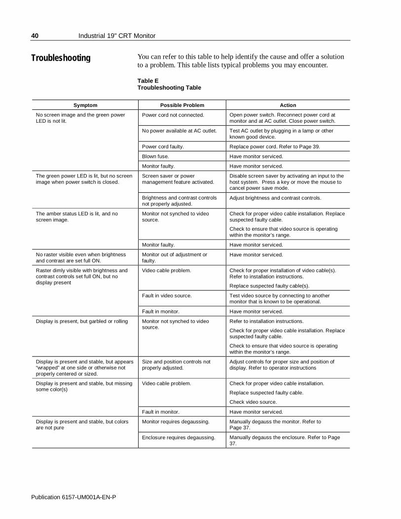
You can refer to this table to help identify the cause and offer a solutionto a problem. This table lists typical problems you may encounter.
Table ETroubleshooting Table
Symptom Possible Problem Action
No screen image and the green powerLED is not lit.
Power cord not connected. Open power switch. Reconnect power cord atmonitor and at AC outlet. Close power switch.
No power available at AC outlet. Test AC outlet by plugging in a lamp or otherknown good device.
Power cord faulty. Replace power cord. Refer to Page 39.
Blown fuse. Have monitor serviced.
Monitor faulty. Have monitor serviced.
The green power LED is lit, but no screenimage when power switch is closed.
Screen saver or powermanagement feature activated.
Disable screen saver by activating an input to thehost system. Press a key or move the mouse tocancel power save mode.
Brightness and contrast controlsnot properly adjusted.
Adjust brightness and contrast controls.
The amber status LED is lit, and noscreen image.
Monitor not synched to videosource.
Check for proper video cable installation. Replacesuspected faulty cable.
Check to ensure that video source is operatingwithin the monitor’s range.
Monitor faulty. Have monitor serviced.
No raster visible even when brightnessand contrast are set full ON.
Monitor out of adjustment orfaulty.
Have monitor serviced.
Raster dimly visible with brightness andcontrast controls set full ON, but nodisplay present
Video cable problem. Check for proper installation of video cable(s).Refer to installation instructions.
Replace suspected faulty cable(s).
Fault in video source. Test video source by connecting to anothermonitor that is known to be operational.
Fault in monitor. Have monitor serviced.
Display is present, but garbled or rolling Monitor not synched to videosource.
Refer to installation instructions.
Check for proper video cable installation. Replacesuspected faulty cable.
Check to ensure that video source is operatingwithin the monitor’s range.
Display is present and stable, but appears“wrapped” at one side or otherwise notproperly centered or sized.
Size and position controls notproperly adjusted.
Adjust controls for proper size and position ofdisplay. Refer to operator instructions
Display is present and stable, but missingsome color(s)
Video cable problem. Check for proper video cable installation.
Replace suspected faulty cable.
Check video source.
Fault in monitor. Have monitor serviced.
Display is present and stable, but colorsare not pure
Monitor requires degaussing. Manually degauss the monitor. Refer toPage 37.
Enclosure requires degaussing. Manually degauss the enclosure. Refer to Page37.
Troubleshooting
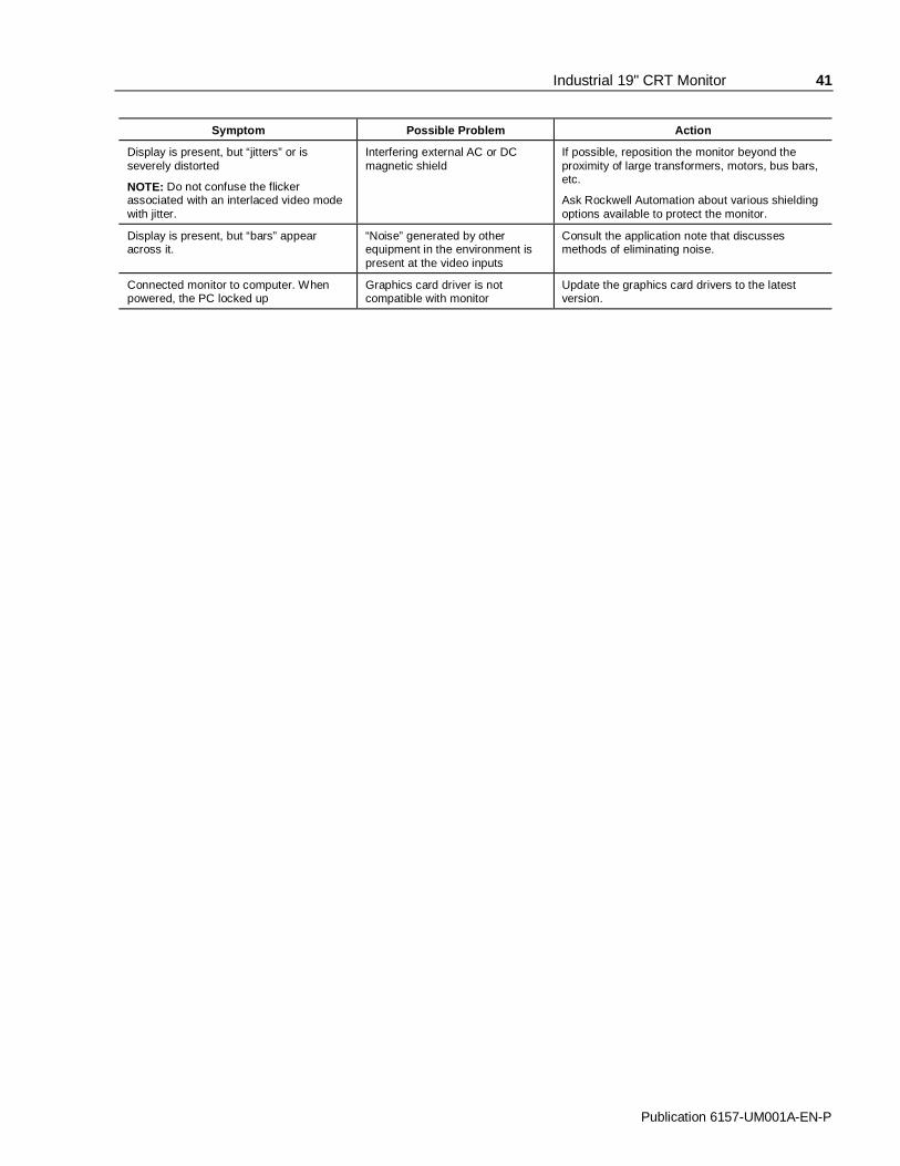
Industrial 19" CRT Monitor 41
Publication 6157-UM001A-EN-P
Symptom Possible Problem Action
Display is present, but “jitters” or isseverely distorted
NOTE: Do not confuse the flickerassociated with an interlaced video modewith jitter.
Interfering external AC or DCmagnetic shield
If possible, reposition the monitor beyond theproximity of large transformers, motors, bus bars,etc.
Ask Rockwell Automation about various shieldingoptions available to protect the monitor.
Display is present, but “bars” appearacross it.
“Noise” generated by otherequipment in the environment ispresent at the video inputs
Consult the application note that discussesmethods of eliminating noise.
Connected monitor to computer. Whenpowered, the PC locked up
Graphics card driver is notcompatible with monitor
Update the graphics card drivers to the latestversion.

42 Industrial 19" CRT Monitor
Publication 6157-UM001A-EN-P
Allen-Bradley offers support services worldwide, with over 75Sales/Support Offices, 512 authorized Distributors and 260 authorizedSystems Integrators located throughout the United States alone, plusAllen-Bradley representatives in every major country in the world.
Local Product Support
Contact your local Allen-Bradley representative for:
• Sales and order support
• Product technical training
• Warranty support
• Support service agreements
Refer to the Rockwell Automation/Allen-Bradley Internet site athttp://www.ab.com for local contact information.
Technical Product Assistance
If you need to contact Allen-Bradley for technical assistance, pleasereview the information in the Troubleshooting section first. Then callyour local Allen-Bradley representative or contact Allen-Bradleytechnical support at (440) 646-5800.
For additional product information and a description of the technicalservices available, visit the Rockwell Automation/Allen-Bradley Internetsite listed above.
Allen-Bradley Support
Industrial 19" CRT Monitor 43
Publication 6157-UM001A-EN-P
$$SSHQGL[ $�SSHQGL[ $� 77RXRXFFKVFKVFUUHHQ 6HHQ 6HHULDOULDO
,QWHUIDFH,QWHUIDFH
All touch controllers are configured by default to provide serialcommunications at 9600 baud, 8 data bits, 1 stop bit, no parity.
For Allen-Bradley monitors equipped with touchscreens, a serialcommunications cable is required. A suitable cable can be obtained fromRockwell Automation or you can create one.
The cable provides a communications channel between the touchscreencontroller, which is mounted inside the monitor, and an RS-232-C serialport on the host computer. Because the touch controller obtains powerfrom the monitor's power supply, no external touch power connectionsare necessary.
Software supplied with the touchscreen must be loaded on the hostcomputer to handle communications with the touch controller over thechannel.
Because the touchscreen emulates a mouse, there may be compatibilityissues involving how the touchscreen emulates mouse buttons, especiallymultiple buttons. For a complete discussion of these issues and how totroubleshoot them, refer to the touchscreen documentation.
This section describes how to set up the touchscreen system using the6157- C Industrial Monitor. Setup involves the following:
• Enabling the touchscreen interface
• Installing the software on the host computer that will handlecommunications with the touchscreen controller
• Performing a calibration
Description
Setting Up theTouchscreen Interface

44 Industrial 19" CRT Monitor
Publication 6157-UM001A-EN-P
Enabling the Touchscreen Interface
The 6157- C Industrial Monitor provides a female DE-9 connector on therear panel. This connector provides the serial interface for the touchcontroller.
Interconnecting wiring to the host serial port connection is shown in thefollowing table.
Table FTouchscreen Interface
Monitor(DCE Device) Host (DTE Device)DE-9 (Female) Signal Description DE-9 (Male) DB-25 (Male)
1 Not Connected (DCD) 1 8
2 Transmit Data (TXD) 2 3
3 Receive Data (RXD) 3 2
4 Data Terminal Ready (DTR) 4 20
5 Common Signal Return (SG) 5 7
6 Not Connected (DSR) 6 6
7 Request To Send (RTS) 7 4
8 Clear To Send (CTS) 8 5
9 Not Connected 9 22
Installing the Touchscreen Driver Software
To install the touchscreen driver software correctly, obtain the followinginformation about the host hardware:
• The COM port in use for the touchscreen. Ensure that the RS-232cable is properly installed between the monitor port and the host’sCOM port.
• The baud rate at which the controller is operating. You will need tomatch the baud rate at the COM port. The controller baud rate isfactory set at 9600.
Note: If you are using older touchscreen software, you may beprompted for the type of touchscreen controller being used.The 6157-C uses the following controllers:• Resistive: Elo TouchSystems Model E271-2210• Capacitive: MicroTouch Model SMT-3
• SAW: Elo TouchSystems Model 2310 Serial

Industrial 19" CRT Monitor 45
Publication 6157-UM001A-EN-P
Once you have obtained this information, install the software using theinstallation disks found in the touchscreen accessory package.
Note: Before installation, you may want to check the touchscreenmanufacturer’s site on the World Wide Web for the latestsoftware drivers. Enter these addresses in your Internetbrowser:
• www.elotouch.com for resistive and SAW touchscreens
• www.microtouch.com for capacitive touchscreens.
After installing the driver software, follow the instructions in thetouchscreen documentation.
Following installation of the touchscreen software and calibration, thetouchscreen is ready to use.
Performing a Calibration

46 Industrial 19" CRT Monitor
Publication 6157-UM001A-EN-P
$$SSHQGL[ %�SSHQGL[ %� 99LGHR &LGHR &DDEOHVEOHV
You can connect the 6157- C Industrial Monitor to the host computerwith an HD-15 connector or with a BNC to HD-15 adapter cable.
An HD-15 video cable equipped with a conventional HD-15 connector ateach end connects the 6157- C Industrial Monitor to the host computer.
Note: This figure is the view looking into the pin end of the maleconnector or solder term end of the female connector.
Figure 13HD-15 Video Connector
The following table provides the pin numbers and corresponding pinassignments for the HD-15 video connector with the DDC2B capability:
Table GStandard HD-15 Video Cable
Monitor (Female) Signal Description Host (Male)
1 Red Video 1
2 Green Video 2
3 Blue Video 3
4 Ground 4
5 Ground 5
6 Red Video Ground 6
7 Green Video Ground 7
8 Blue Video Ground 8
9 Not Used 9
10 Sync Ground 10
11 Ground 11
12 Bi-Directional Data (SDA) 12
13 Horizontal Sync 13
14 Vertical Sync (VCLK) 14
15 Data Clock (SCL) 15
HD-15 Connectors

Industrial 19" CRT Monitor 47
Publication 6157-UM001A-EN-P
The BNC cables you use with this monitor uses a conventional HD-15connector at the monitor end to connect the 6157- C Industrial Monitorto the host computer with five BNC connectors:
• R, B, and G: Red, Green, and Blue input connectors to establishcolor. These are used for RS-343 analog signals.
• HS/CS: Separate horizontal/composite sync signal from the videosource.
• VS: Separate vertical sync signal from the video source.
Figure 14BNC Video Connector
The following table describes the signal types you can use with theseBNC connectors:
Table HBNC Signal Types
BNC Signal Type Description R G B HS/CS
VS
Sync-on-Green Use the three video connectors. Horizontaland vertical syncs are supplied on the greenvideo line.
X X X
SeparateComposite Sync
Use the three video connectors plus thehorizontal sync/composite sync input.
X X X X
SeparateHorizontal andVertical Sync
Use the three video connectors plus thehorizontal sync/composite sync and verticalsync input.
X X X X X
BNC Connectors

48 Industrial 19" CRT Monitor
Publication 6157-UM001A-EN-P
Specifications
Display
CRT Type 19 in. diagonal pure flat, 0.25mm dot pitch
RGB short persistence, Anti-glare treated, Anti-static,INVAR shadow mask
Degaussing Manual and automatic
Nominal Display Area
(4:3 aspect) Horizontal
(4:3 aspect) Vertical
Diagonal
14.17 in. (360mm)
10.63 in. (270mm)
17.72 in. (450mm)
Non Linearity (CHP Method)
Horizontal
Vertical
7% max
6% max
Regulation 2mm max peak deviation
Misconvergence 0.3mm max inside (centered circle 225mm diameter)0.4mm max outside
Luminance (typical) 35 fL, small white square
CIE coordinates
White x:=0.283, y:=0.298 (9300K +8MPCD)
Video
Resolution 1600x1200 max at 75Hz max
Supported Standards IBM VGA (640x480 at 60Hz, 720x400 @ 70 Hz )
VESA (640x480 at 60/75/85Hz, 800x600 at60/75/85 Hz, 1024x768 at 60/75/85 Hz, 1280x1024 at60/75/85 Hz, 1600x1200 at 75 Hz)
Horizontal Scan Rate Variable: 30-98kHz
Vertical Scan Rate Variable: 50H-160Hz
Video Dot Rate 210MHz
Video Input Signal RGB analog (white level = 0.714V above ref. black,into 75 Ohms, single ended)
Sync Input Signals • Separate horizontal and vertical sync control,TTL signal levels
• Sync on green
• Composite sync
Input Connection HD-15, Plug and Play DDC1/2B
Controls and Indicators Front Panel: On-Screen Display, Power, Syncdetection
Operator Input Touchscreen Option: Resistive, capacitive, or SAWtouchscreen, with serial controller and driver software

Industrial 19" CRT Monitor 49
Publication 6157-UM001A-EN-P
Environmental
Panel RatingPanel MountRack Mount
NEMA 4/4X/12, (IP65/IP52) (6157-CE/6157-CF)NEMA 1 (IP10) (6157-CB)
Operating Temperature 0ºC to 40ºC
Storage Temperature -20ºC to 60ºC
Relative Humidity 10% to 90% non-condensing
Operating Altitude Sea level to 10,000 ft (3,048m)
Non-Operating Altitude Sea level to 40,000 ft (12,192m)
Operating ElectrostaticDischarge
8.0K VDC (IEC 801-2, level 3)
Non-Operating ElectrostaticDischarge
20.0K VDC
Operating Shock 10g (1/2 sine, 11msec)
Non-Operating Shock 20g (1/2 sine, 11msec)
Operating Vibration 0.003in. p-p, 5-57Hz,0.5g peak, 57-640Hz sine
Non-Operating Vibration 0.006in. p-p, 5-57Hz,1.0g peak 51-640Hz sine
Electrical
Line Voltage 100-130/198-264 VAC, autoswitching
Line Frequency 50-60Hz
Ground Leakage 1.0 uA max at 1.5K VDC
Power Consumption 135W max
Physical
Panel Mount
Panel Bezel Dimensions (W x H x D)
19.0 in. x 15.7 in. x 0.43 in. (483mm x 399mm x11mm)
Overall Dimensions (from rear surface of front panel to back)
16.75 in. x 14.0 in. x 18.1 in. (426mm x 356mm x460mm)
Net Weight 64lb (29.0kg)
Rack Mount
Panel Bezel Dimensions (W x H x D)
19.0 in. x 15.7 in. x 0.4 in. (482mm x 399mm x 10mm)
Overall Dimensions (from rear surface of front panel to back)
16.75 in. x 14.0 in. x 18.2 in. (426mm x 356mm x462mm)
Net Weight 64lb (29.0kg)
Certifications - Agency Approvals
UL 1950 Recognized Component,C-UL 950 Recognized Component
LVD (73/23/EEC) EN 60950 (per UL 1950 3rd ed. without D3 dev.)
EMC (89/336/EEC) Emissions Immunity
EN 50081-2EN 50082-2
Australian C-Tick
DHHS DHHS 21 CFR 1020.10 Compliant
FCC Class A

Publication 6157-UM001A-EN-P998078-010
Copyright 2000 Rockwell Automation Corporation. All rights reserved. Printed in USA.
IBM is a registered trademark of International Business Machines Corporation.
VGA is a trademark of International Business Machines Corporation.
PC AT is a trademark of International Business Machines Corporation.
Microsoft is a registered trademark of Microsoft Corporation.
Microsoft Windows is a trademark of Microsoft Corporation.
Chassis-Trak is a registered trademark of the General Devices Company.
Rockwell Automation helps its customers receive a superior return on their investment by bringingtogether leading brands in industrial automation, creating a broad spectrum of easy-to-integrateproducts. These are supported by local technical resources available worldwide, a global network ofsystem solutions providers, and the advanced technology resources of Rockwell.
Worldwide representation. Argentina • Australia • Austria • Bahrain • Belgium • Bolivia • Brazil • Bulgaria • Canada • Chile • China, People’s Republic of • Colombia • Costa Rica • Croatia • Cyprus • CzechRepublic • Denmark • Dominican Republic • Ecuador • Egypt • El Salvador • Finland • France • Germany • Ghana • Greece • Guatemala • Honduras • Hong Kong • Hungary •Iceland • India • Indonesia • Iran • Ireland • Israel • Italy • Jamaica • Japan • Jordan • Korea • Kuwait • Lebanon • Macau • Malaysia • Malta • Mexico • Morocco • The Netherlands •New Zealand • Nigeria • Norway • Oman • Pakistan • Panama • Peru • Philippines • Poland • Portugal • Puerto Rico • Qatar • Romania • Russia • Saudi Arabia • Singapore •Slovakia • Slovenia • South Africa, Republic of • Spain • Sweden • Switzerland • Taiwan • Thailand • Trinidad • Tunisia • Turkey • United Arab Emirates • United Kingdom • UnitedStates • Uruguay • Venezuela
Rockwell Automation Headquarters, 1201 South Second Street, Milwaukee, WI 53204-2496 USA, Tel: (1) 414 382-2000, Fax: (1) 414 382-4444Rockwell Automation European Headquarters, Avenue Hermann Debroux, 46 1160 Brussels, Belgium, Tel: (32) 2 663 06 00, Fax: (32) 2 663 06 40Rockwell Automation Asia Pacific Headquarters, 27/F Citicorp Centre, 18 Whitfield Road, Causeway Bay, Hong Kong, Tel: (852) 2887 4788, Fax: (852) 2508 1846World Wide Web: http://www.ab.com