tv and monitor crt (picture tube) information - gamesx o crt deflection angle o crt contrast ratio...
TRANSCRIPT

TV and Monitor CRT (Picture Tube)Information
Version 1.92
Copyright © 1994-2003Samuel M. Goldwasser
--- All Rights Reserved ---
For contact info, please see the Sci.Electronics.Repair FAQ Email Links Page.
Reproduction of this document in whole or in part is permitted if both of thefollowing conditions are satisfied:
1. This notice is included in its entirety at the beginning.
2. There is no charge except to cover the costs of copying.
Table of Contents• Preface
o Author and Copyright
o DISCLAIMER
o Acknowledgements
• Introduction
o Scope of This Document
o Related Documents
o Additional Information on CRTs
• CRT Safety Issues
o Electrical Safety
o Safe Discharging of Capacitors in TVs and Video Monitors
o Additional Information on Discharging CRTs
o Warning about disconnecting CRT neck board
o CRT Implosion Risk?
o Picture Tube Implosion IS Possible - But You Really Need Work at It!
o Risks from CRT Scratches?
o Disposing of Dead TVs or Monitors (CRTs and Charged HV Capacitors
• CRT Construction and Characteristics
o Why is the CRT Still Dominant?
o Comparison of CRT Types
o Color CRT Construction
o Assembly of Color CRTs
o CRT Fine Tuning
o Northern/Southern Hemisphere Corrections and Adjustments
o Tubes for All Nations
o So What Does It Mean to Have a Trinitron CRT?
o Why are There Fine Lines Across My Trinitron Monitor or
o Differences between Trinitron and Diamondtron CRTs
o Some History of In-Line Gun CRTs
o How Far is the Shadow Mask from the Phosphor Screen
o How is the Shadow Mask Mounted Inside the CRT?
o Why is the Shadow Mask or Aperture Grill Made of a Magnetic Material?
o Why do CRTs Use Red, Green, and Blue rather than Red, Yellow, Blue?
o Purpose of a Separate CRT Faceplate
o Leaded Glass and CRT Coatings
o Flat Versus Non-Flat CRTs
• Resolution, Dot Pitch, and Other CRT Specifications
o Color CRT Resolution - Focus and Dot/Slot/Line Pitch
o A Discussion of Issues Relating to Monitor and CRT Resolution
o About the Quality of Monitor Focus
o How to Compute Effective Dot Pitch
o Dot Pitch of TV CRTs
o CRT Aspect Ratio

o CRT Deflection Angle
o CRT Contrast Ratio
• Effects of External Magnetic Fields on CRTs
o Magnetic Interference and Shielding
o Comments on Speaker Shielding
o Why Magnetic Fields May Cause the Picture to Rotate
o Best Direction to Face a Monitor?
o Ways Around North/South or Other Sensitivity to Magnetic Fields
o Additional Comments/Summary on Northern/Southern Hemisphere Issues
o Orientation Considerations for Projection TVs
• Picture Quality and Appearance Issues
o Why Does the Intensity Appear So Non-Uniform in Bright Areas?
o Comments On Color Purity, Set Orientation, and Doming
o Difference in Color Rendition Between CRTs
o Contour Lines on High Resolution Monitors - Moire
o Moire and Shadow Mask Dot Pitch
o Isolated Spots on Display
o Purple Blob - or Worse
o Magnet Fix for Purity Problems - If Duct Tape Works, Use It!
o How Much Tilt is Acceptable?
o What is Doming?
o Afterglow - Phantom Patterns on CRT After Shutoff
o Discussion on the causes of color flare
• Magnetic Fields and Degaussing
o Degaussing (Demagnetizing) a CRT
o How Often to Degauss
o Ultra Cheap Degaussing Coil
o Bob Myers' Notes on Degaussing
o Degaussing after lightning strike

o Degaussing Humor - If it Works, Use It!
o Can a Really Strong Magnet Permanently Damage the
o WARNING about degaussing late model Sony Trinitron CRTs
• CRT Related Adjustments
o Principles of Purity and Convergence Adjustment
o Detailed Purity and Static Convergence Adjustment Procedure
o Tony's Notes on Setting Convergence on Older Delta Gun CRTs
o Jerry's Comments on Convergence and Other Advanced Adjustments
o CRTs with No Purity or Static Convergence Rings
o Projection Set Convergence Adjustment Principles
o Monitor Tune-Up?
o A Discussion on Correction Magnets
• CRT and CRT Related Maintenance and Repair
o Preventive Maintenance - Care and Cleaning CRT?
o Shorts in a CRT
o Providing Isolation for a CRT H-K Short
o Rescuing a Shorted CRT
o Determining if Your CRT is up to Air
o Scratches or Other Damage to the CRT Face
• CRT Degradation
o CRT Aging - Effects on Electrical Characteristics and Performance
o CRT Age Resulting in Dark Picture
o Brightening an Old CRT
o Checking the Age of the CRT
• CRT Rejuvenation
o What is CRT Rejuvenation?
o CRT Degradation and Rejuvenation?
o More Comments on CRT Rejuvenation
o Home-Made CRT Rejuvenator 1

o Home-Made CRT Rejuvenator 2
o Home-Made CRT Rejuvenator 3
• Items of Interest
o Lifespans of Monitors
o Monitor Life, Energy Conservation, and Laziness
o Thernal Cycling and Component Life
o Why are Prices of Video Monitors So High Compared to
o Expected Life of TV CRTs
o Problems with Designing a Combination TV and Computer Monitor
o Picture Tube Disassembly for Demonstration
o Turning a Large CRT Faceplate into the Side of a Fish Tank
o Why do TVs Overscan?
o What is Aquadag?
o Why are Indirectly Heated Cathodes Used in CRTs
o Frequency Response of CRTs
• CRT Service Information
o How to Read CRT Part Numbers
o Typical Color CRT Pinout
o CRT Substitution
o CRT Replacement Worth It?
o Rebuilt CRTs
o What Does It Take to be a Picture Tube Rebuilder, Really?
o Shipping Damage: Why Monitors are Like
• Back to CRT FAQ Table of Contents.
Preface
Author and CopyrightAuthor: Samuel M. GoldwasserFor contact info, please see the Sci.Electronics.Repair FAQ Email Links Page.

Copyright © 1994-2003All Rights ReservedReproduction of this document in whole or in part is permitted if both of the followingconditions are satisfied:1.This notice is included in its entirety at the beginning.2.There is no charge except to cover the costs of copying.
DISCLAIMERWe will not be responsible for damage to equipment, your ego, blown parts, county widepower outages, spontaneously generated mini (or larger) black holes, planetary disruptions, orpersonal injury that may result from the use of this material.
AcknowledgementsSpecial thanks to Bob Myers (A HREF="mailto:[email protected]">[email protected]) andJeroen Stessen (A HREF="mailto:[email protected]">[email protected]) for their contributions to this document through theirnewsgroup postings and private email.
• Back to CRT FAQ Table of Contents.
Introduction
Scope of This DocumentThis document contains a collection of information relating to CRT (picture tube)construction, characteristics, problems, maintenance, troubleshooting, and repair. This wasoriginally from the TV and monitor repair guides of the Sci.Electronics.Repair FAQ but hasbeen moved here due to its being of general interest.Most new CRT related information originating on the sci.electronics.repair,comp.sys.ibm.pc.hardware.video, or other USENET newsgroups will be included here ratherthan in those other documents.
Related DocumentsThe following may be of interest and cover many relavent topics related to CRT basedequipment:
• Safety Guidelines for High Voltage and/or Line Powered Equipment.
• Notes on the Troubleshooting and Repair of Computer and Video Monitors.
• Notes on the Troubleshooting and Repair of Television Sets.
• Performance Testing of Computer and Video Monitors.
• Notes on Approaches to using Fixed Frequency Monitors on PCs.
• Notes on Video Conversion.
Additional Information on CRTsThe PC Technology Guide has some information with nice diagrams on both CRT and flatpanel displays. This site is well worth visiting to get an idea of the construction, operation,and problems for a variety of display technologies.

(From: David Moisan ([email protected]).)I've seen a few such pictures and I was fortunate enough to find a book on color CRTs thatexplained quite a few things:
Color Television Picture TubesMorell, Law, Ramberg, HaroldISBN 0-12-022151-0.
I'm not sure if its still in print but you might check out your local university library.)If you are lucky enough to see "The Secret Life of Machines" on The Learning Channel (orwas, last time I saw it), there's an episode on the secret life of the TV. It's excellent! Thecreator and presenter, Tim Hunkin, has a weird sense of humor but he's very well informedand quite gifted in the way he demonstrates difficult-to-explain concepts. In the openingscene, he showed off a TV that he sawed in half, showing the CRT construction very clearly.(He must have let the air into the tube, then used a diamond saw to cut it; that's the only way itcould be done without glass everywhere!)(Of course, he may not *actually* have cut a TV in half - manufacturers no doubt maintainprops of this sort!)
• Back to CRT FAQ Table of Contents.
CRT Safety Issues
Electrical SafetyTVs and computer or video monitors are among the more dangerous of consumer electronicequipment when it comes to servicing. (Microwave ovens are probably the most hazardousdue to high voltage at flesh frying and cardiac arresting high power.)There are two areas which have particularly nasty electrical dangers: the non-isolated linepower supply and the CRT high voltage.Major parts of nearly all modern TVs and many computer monitors are directly connected tothe AC line - there is no power transformer to provide the essential barrier for safety and tominimize the risk of equipment damage. In the majority of designs, the live parts of the TV ormonitor are limited to the AC input and line filter, degauss circuit, bridge rectifier and mainfilter capacitor(s), low voltage (B+) regulator (if any), horizontal output transistor and primaryside of the flyback (LOPT) transformer, and parts of the startup circuit and standby powersupply. The flyback generates most of the other voltages used in the unit and provides anisolation barrier so that the signal circuits are not line connected and safer.Since a bridge rectifier is generally used in the power supply, both directions of the polarizedplug result in dangerous conditions and an isolation transformer really should be used - toprotect you, your test equipment, and the TV, from serious damage. Some TVs do not haveany isolation barrier whatsoever - the entire chassis is live. These are particularly nasty.The high voltage to the CRT, while 200 times greater than the line input, is not nearly asdangerous for several reasons. First, it is present in a very limited area of the TV or monitor -from the output of the flyback to the CRT anode via the fat red wire and suction cupconnector. If you don't need to remove the mainboard or replace the flyback or CRT, thenleave it alone and it should not bite. Furthermore, while the shock from the HV can be quitepainful due to the capacitance of the CRT envelope, it is not nearly as likely to be lethal sincethe current available from the line connected power supply is much greater.
Safe Discharging of Capacitors in TVs and Video Monitors

It is essential - for your safety and to prevent damage to the device under test as well as yourtest equipment - that large or high voltage capacitors be fully discharged before measurementsare made, soldering is attempted, or the circuitry is touched in any way. Some of the largefilter capacitors commonly found in line operated equipment store a potentially lethal charge.This doesn't mean that every one of the 250 capacitors in your TV need to be dischargedevery time you power off and want to make a measurement. However, the large main filtercapacitors and other capacitors in the power supplies should be checked and discharged if anysignificant voltage is found after powering off (or before any testing - some capacitors (likethe high voltage of the CRT in a TV or video monitor) will retain a dangerous or at leastpainful charge for days or longer!)The technique I recommend is to use a high wattage resistor of about 100 ohms/V of theworking voltage of the capacitor. This will prevent the arc-welding associated withscrewdriver discharge but will have a short enough time constant so that the capacitor willdrop to a low voltage in at most a few seconds (dependent of course on the RC time constantand its original voltage).Then check with a voltmeter to be double sure. Better yet, monitor while discharging (notneeded for the CRT - discharge is nearly instantaneous even with multi-M ohm resistor).Obviously, make sure that you are well insulated!
• For the main capacitors in a switching power supply which might be 100 uF at 350 Vthis would mean a 5K 10W resistor. RC=.5 second. 5RC=2.5 seconds. A lowerwattage resistor can be used since the total energy in not that great. If you want to bemore high tech, you can build the capacitor discharge circuit outlined in thecompanion document: Capacitor Testing, Safe Discharging, and Other RelatedInformation. This provides a visible indication of remaining charge and polarity.
• For the CRT, use a high wattage (not for power but to hold off the high voltage whichcould jump across a tiny 1/4 watt job) resistor of a few M ohms discharged to thechassis ground connected to the outside of the CRT - NOT SIGNAL GROUND ONTHE MAIN BOARD as you may damage sensitive circuitry. The time constant is veryshort - a ms or so. However, repeat a few times to be sure. (Using a shorting clip leadmay not be a bad idea as well while working on the equipment - there have been toomany stories of painful experiences from charge developing for whatever reasonsready to bite when the HV lead is reconnected.) Note that if you are touching the littleboard on the neck of the CRT, you may want to discharge the HV even if you are notdisconnecting the fat red wire - the focus and screen (G2) voltages on that board arederived from the CRT HV.
WARNING: Most common resistors - even 5 W jobs - are rated for only a fewhundred volts and are not suitable for the 25kV or more found in modern TVs andmonitors. Alternatives to a long string of regular resistors are a high voltage probe or aknown good focus/screen divider network. However, note that the discharge timeconstant with these may be a few seconds. Also see the section: AdditionalInformation on Discharging CRTs.If you are not going to be removing the CRT anode connection, replacing the flyback,or going near the components on the little board on the neck of the CRT, I would juststay away from the fat red wire and what it is connected to including the focus andscreen wires. Repeatedly shoving a screwdriver under the anode cap risks scratchingthe CRT envelope which is something you really do not want to do.
Again, always double check with a reliable voltmeter!TReasons to use a resistor and not a screwdriver to discharge capacitors:

1. It will not destroy screwdrivers and capacitor terminals.
2. It will not damage the capacitor (due to the current pulse).
3. It will reduce your spouse's stress level in not having to hear those scary snaps andcrackles.
Additional Information on Discharging CRTsYou may hear that it is only safe to discharge from the Ultor to the Dag. So, what the @#$%are they talking about? :-).BTW, don't wash your CRTs even if the Maid complains about the filth until you haveconfirmed that your 'Dag isn't water soluble (maybe that's why it has 'aqua' in the name!). Itmay all come off! Wipe off the dirt and dust with a cloth (and stay away from the HVconnector or make sure it is discharged first!).(From: Asimov ([email protected]).)'Dag' is short for Aquadag. It is a type of paint made of a graphite pigment which isconductive. It is painted onto the inside and outside of picture tubes to form the 2 plates of ahigh voltage filter capacitor using the glass in between as dielectric. This capacitor is between.005uF and .01uF in value. This seems like very little capacity but it can store a substantialcharge with 25,000 volts applied.The outside "dag" is always connected to the circuit chassis ground via a series of springs,clips, and wires around the picture tube. The high voltage or "Ultor" terminal must bedischarged to chassis ground before working on the circuit especially with older TV's whichdidn't use a voltage divider to derive the focus potential or newer TV's with a defective opendivider.
Warning about disconnecting CRT neck boardSome manufacturers warn against powering a TV or monitor CRT without the CRT neckboard connected. Apparently, without something - anything - to drain the charge resultingfrom the current flow due to residual gas ions inside the CRT, the shortest path may bethrough the glass neck of the tube to the yoke or from the pins outside the CRT to whatever isnearby. There aren't many ions in a modern CRT but I suppose a few here, a few there, andeventually they add up to enough to cause a major disaster at least on some CRTs.This is probably not a problem on small CRTs but for large ones with high high voltages andhigh deflection angles where the glass of the neck is very thin to allow for maximumdeflection sensitivity, the potential does exist for arcing through the glass to the yoke to occur,destroying the CRT.There is really no way to know which models will self destruct but it should be possible toavoid such a disaster by providing a temporary return path to the DAG ground of the CRT(NOT SIGNAL GROUND!!) via the focus or G2 pins preferably through a high value highvoltage rated resistor just in case one of these is shorted.This probably applies mostly to large direct-view TVs since they use high deflection angleCRTs but it won't hurt to take appropriate precautions with video and computer monitors aswell.
CRT Implosion Risk?Also see the section: Disposing of Dead TVs or Monitors (CRTs and Charged HVCapacitors).(From: Jeroen Stessen ([email protected]).)I have checked with our CRT expert and he thinks that any 'normal' type of scratch does notpose any danger. Usual disclaimer applies ... (what is 'normal'?)

The front of the tube is much thicker and stronger than the rear. It has to be, to withstand theair pressure, because the curvature radius is so much larger. You won't break it by throwing aslipper at it. The neck is in fact very easy to break, usually without causing injuries to anyone.Normally, if the tube should implode, the rimband (the tensioned steel band around the rim ofall modern CRTs of any size) prevents the glass from flying outward too far. Every tube typehas to pass tests in which it is deliberately imploded and it is checked whether any largeshrapnel flies too far out.What *is* very dangerous is a CRT with its rimband missing, or a CRT which never had adecent rimband in the first place (like some dubious Russian-made samples we once saw).Such a tube should not be handled at all. NEVER ever attempt to remove the rimband for andreason!I just saw a picture tube that was broken due to dropping the (entire) TV on one corner. In thecone (the backside) there are open cracks of some 3 feet length in total. Nevertheless all theglass is still in its original place and it looks as if no glass has flown outward. The faceplate isstill intact. So in this case nobody would have got hurt. I remember reading about Americans(who else?) who tried to shoot CRT's with smaller rifles, with little or no success.Does this comfort you? Get out the shotgun and have a go at it!Or, perhaps, the following:(From: Ren Tescher ([email protected]).)Our 6 month old 20" SGI color monitor (model GDM-20D11) lost a fight with a fork lift. Thecase is intact, the CRT probably still has a vacuum, but the outer layer of glass on the screenis shattered.
Picture Tube Implosion IS Possible - But You Really Need To Work at It!As noted elsewhere in this document, picture tube implosion is a hazard but under normalconditions, quite unlikely. Someone wrote:
"I heard somewhere that in the early days of TV, the tubes had a tendency toimplode at the drop of a hat. (Due to poor design?) In order to prevent flyingglass, the sets had a plastic sheet in front of the screen. Obviously, modern setsno longer have this. How safe are modern CRT screens in terms of impactdamage etc?"
Well, it isn't quite as simple as that..... However, even if CRT implosion is one of those highlyunlikely events, the downside is that should it occur in just the wrong way, the consequencescan be disastrous. So, I wouldn't depend on the experiences below to guide you! Treat a CRTabout the same way you would an armed nuclear bomb. OK, well maybe just 10 sticks ofdynamite. :-)(From: Dan Evens ([email protected]).)In high school, our electronics teacher did a demo for each class. He saved out an old black-and-white tube for each class and set up a place to break it. Put the tube on the ground by abrick wall, with a hammer suspended on a wire from the top of the wall. Did it on thedriveway so that the glass would be easier to pick up. The tube was placed image-side down.First he pulled the hammer back about 20 feet and just let it go. It bounced off the tube. Thiswas to show that such tubes are pretty tough. Then he pulled the hammer back and gave it apretty good shove, turning his back to the tube and moving quickly away from it. (Let's faceit, the guy could probably have found a safer way to do this.)Palm sized chunks of glass flew 50 feet. The noise was quite impressive. The thickness of theimage plate of the tube was also quite impressive. Kind of looked like a porthole on asubmarine. This was from the tube of a small black-and-white TV, about 14 inches or so. Oneof the larger colour models might be a LOT more violent.
If I was handling these things in such a way as to have the possibility of dropping one, I'dinsist on body armor and face protection. And if it involves a picture tube, I insist oncompetent trained professionals for service.(From: Matthias Meerwein ([email protected]).)They ARE quite safe. I've got several TVs and computer monitors in for repair that had beendropped. None of them had an imploded CRT. The damage encountered ranged from:
• Broken circuit boards, often around the flyback transformer (the most heavy weightpart on the board) - This is quite easily repairable.
• Shadow mask inside the tube knocked out of position (mostly in trinitron tubes due totheir heavy aperture grille construction) - this renders the tube (and thus usually theset) a dumpster candidate.
• Neck of tube broken of (usually when the set hit the floor back end first) - obviouslyjunk.
Furthermore, I did some experimentation with junk sets:
• 26 inch color TV with back panel removed placed face-down under a bridge. Droppeda ~10 pound brick from top of the bride (about 10 ft high) into the glass funnel of thetube. Result: Funnel of tube shattered, faceplate intact. All glass shards (most of themrather large) were lying inside the set's cabinet - no flying glass.
• 14 inch B/W computer monitor tube dropped from the second story onto concretefloor, hitting the ground faceplate-first. Result: tube shattered into thousands of smallglass particles (the largest ones were about one inch in size), but all debris was locatedon one heap - none of them traveled farther than about three feet.
Conclusion: According to my experience, spectacular picture tube implosions are somethinglike cars in movies that explode upon roll-over, hitting a tree or driving down the cliffs: anurban legend.(From: Clifton T. Sharp Jr. ([email protected]).)With today's tubes, that's more or less true (although walking through a picture tube plant canbe instructive as you hear the exploding tubes). With older tubes it was a hazard. With pre-1960 tubes it was a big one. My old boss in the TV service, who I trusted not to exaggerateabout such things, told me stories of setting a picture tube near a second-floor window, havingthem fall to the sidewalk and literally blow a hole in the sidewalk. I can tell you factually andfirst-person that although he took few precautions with other things, when he had to "pop" apicture tube in the dumpster he never ever ever did it without safety glasses, a shield and asix-foot piece of heavy pipe. (I stopped working there around 1973.)
Risks from CRT Scratches?A really deep long scratch or gouge on the CRT face should be considered a serious safetyhazard as it may reduce the structural integrity and increase the risk of implosion. However,you would likely need a hammer and chissel or diamond tipped tool to make scratches thatdeep. It is very unlikely that such scratches could come from any reasonable normal use.Dropping it from a cliff, deliberate use of a glass cutter, the use of a really really BIGhammer, or 12 gauge shotgun, might perhaps be sufficient.This is more of a concern for modern CRTs that usually have 'integral implosion protection' -that steel rimband around the outside near the front. Older CRTs used either (1) a separatesafety shield - that laminated glass plate in front of your grandmom's TV - or (2) a secondcontoured glass panel bonded to the actual tube face. In both of these cases, the second panelis protective and cosmetic but is not part of the structure of the CRT. Therefore, any damage

to it does not significantly compromise the tube. In the case of modern CRTs, the steel bandin conjunction with the basic tube envelope is used to maintain the integrity of the overallCRT. In addition should implosion occur as a result of catastrophic damage, the rimband willreduce the range and velocity of flying debris.Also see the section: CRT Implosion Risk?.BTW, scratches in the CRT have absolutely no effect on X-ray emission. X-rays are blockedlong before they come anywhere near the surface and glass has very little effect on theirdirection. Any scratch deep enough to have any detectable effect on X-ray emission (actually,it would need to be an inch deep gouge) would have caused the tube to implode.
Disposing of Dead TVs or Monitors (CRTs and Charged HV Capacitors)I don't know what the law says, but for safety, here is my recommendation:Treat the CRT with respect - the implosion hazard should not be minimized. A large CRT willhave over 10 tons of air pressure attempting to crush it. Wear eye protection whenever dealingwith the CRT. Handle the CRT by the front - not the neck or thin funnel shaped envelope.Don't just toss it in the garbage - it is a significant hazard. The vacuum can be safely released(Let out? Sucked in? What does one do with an unwanted vacuum?) without spectaculareffects by breaking the glass seal in the center of the CRT socket (may be hidden by theindexing plastic of the socket). Cover the entire CRT with a heavy blanket when doing this foradditional protection. Once the vacuum is gone, it is just a big glass bottle though there maybe some moderately hazardous materials in the phosphor coatings and of course, the glass andshadow mask will have many sharp edges if it is broken.In addition, there could be a nice surprise awaiting anyone disconnecting the high voltagewire - that CRT capacitance can hold a charge for quite a while. Since it is being scrapped, ascrewdriver under the suction cap HV connector should suffice.The main power supply filter caps should have discharged on their own after any reasonablelength of time (measured in terms of minutes, not days or years).Of course around here, TVs and monitors (well, wishful thinking as I have yet to see a decentmonitor on the curb) are just tossed intact which is fortunate for scavengers like me whowould not be happy at all with pre-safed equipment of this type!(From: Jeroen Stessen ([email protected]).)We have a procedure for disposing of used CRT's. The vacuum must be broken to avoidfuture implosion, like when it will be crushed by the dumpster truck press. That's NOT funny!One method is to punch or drill a small hole in the anode contact, which is made of a softmetal. But take care of the electrical discharge of the aquadag capacitance first!!!The other method is to break the stem in the centre of the socket pins. This is the stem throughwhich the tube was pumped empty during manufacturing. It breaks off easily (after you haveremoved the plastic part around the pins).You want to avoid making too large holes, like for example from chopping off the entire neckin one blow with a hammer.
• Back to CRT FAQ Table of Contents.
General CRT Construction and Characteristics
Why is the CRT Still Dominant?Currently, most TVs and computer monitors are still based on the Cathode Ray Tube (CRT)as the display device. However, many hand-held TVs, portable equipment, laptop computers,and the screens inside video projectors now use flat panel technology, mostly Liquid Crystal
Displays - LCDs. These are a lot less bulky than CRTs, use less power, and have bettergeometry - but suffer from certain flaws.First, the picture quality in terms of gray scale, color, and brightness is generally inferior to adecent analog monitor. The number of distinct shades of gray or distinct colors is a lot morelimited. They are generally not as responsive as CRTs when it comes to real-time video whichis becoming increasingly important with multimedia computers. Brightness is generally not asgood as a decent CRT display. And last but not least, the cost is still much much higher dueboth to the increased complexity of flat panel technology and lower production volumes(though this is certainly increasing dramatically). It is really hard to beat the simplicity of theshadow mask CRT. For example, a decent quality active matrix color LCD panel may add$1000 to the cost of a notebook computer compared to $200 for a VGA monitor. More ofthese panels go into the dumpster than make it to product do to manufacturing imperfections.A variety of technologies are currently competing for use in the flat panel displays of thefuture. Among these are advanced LCD, plasma discharge, and field emission displays. Onlytime will tell which, if any survives to become **the** picture-on-the-wall or notepad display- at reasonable cost.At least one company is about to introduce a 42 inch diagonal HDTV format flat plasma panelmultisystem color TV/monitor which will accept input from almost any video or computersource. Its price at introduction will be more than that of a typical new automobile - about$15,000! :-) Thus, at first, such sets will find their way into business conference rooms andmansions rather than your home theater but prices will drop over time.Projection - large screen - TVs and monitors, on the other hand, may be able to takeadvantage of a novel development in integrated micromachining - the Texas Instruments Inc.Digital Micromirror Device (DMD). This is basically an integrated circuit with a tiltablemicromirror for each pixel fabricated on top of a static memory - RAM - cell. This technologywould permit nearly any size projection display to be produced and would therefore beapplicable to high resolution computer monitors as well as HDTV. Since a reflective mediumis used in this device, the light source can be as bright as needed. Commercial products basedon the DMD are beginning to appear.
Comparison of CRT Types
"Could someone please help to elucidate the comparative advantages of eachtechnology? I know how they work but do not know which is advantageousand why."
(From: Jeroen Stessen ([email protected]).)Trinitron is Sony technology. The shadow mask (called the aperture grille) consists of verticalwires under tension. The mask is always straight in the vertical direction and curved in thehorizontal direction, thus the shape is a cylinder. The tube surface is also cylindrical, whichcauses some strange effects, particularly funny mirror reflections of yourself. Because thewires are under a lot of tension, the internal tube structure must be very strong and thusrelatively heavy. Because the glass surface is cylindrical instead of spherical, the glass mustbe thicker and heavier too, to withstand atmospheric pressure.Heavier always equates to more expensive!The electron gun construction is also different: there are still 3 guns (not one as some maything but the 3 guns share one main lens. (The assembly of focusing grids is called a lens, inanalogy to the optical principle.) There are still 3 cathodes and 3 G1s, as usual. The largediameter lens has the advantage of less spherical aberration (and thus a sharper spot) but thedisadvantage of large physical length which means a deeper cabinet.In the deflection coil design another compromise is found between spot quality, purity andconvergence. As a result horizontal convergence must be helped by an auxiliary dynamic
convergence waveform (on an extra convergence coil?). This adds to cost and canoccasionally give an interesting failure of the horizontal convergence.The best non-Trinitron (or clone) CRTs use a conventional shadow mask made of Invar -originally Matsushita technology; Philips uses it too. The shadow mask is of the standardshape (spherical metal plate with holes in it) but it is made of a special alloy with a 7 timeslower coefficient of thermal expansion than regular iron. This allows a brighter picture withless purity errors.The problem with regular shadow masks is 'doming'. Due to the inherent principle of shadowmasks, 2/3 or more of all beam energy is dissipated in the mask. Where static bright objectsare displayed, it heats up several hundred degrees. This causes thermal expansion, with localwarping of the mask. The holes in the mask move to a different place and the projections ofthe electron beams will land on the wrong colours: purity errors. The use of invar allowsabout 3 times more beam current for the same purity errors. See the section: What isDoming?.Combating purity errors is a necessity due to 2 trends:
• Flatter picture tubes: flatter shadow masks are more sensitive to doming
• Darker (glass) picture tubes: this gives more contrast but more beam current is neededfor enough brightness
The trinitron aperture grill shadow mask is inherently insensitive to doming as long as thetension in the wires remains positive. If the wires become too long then they become moresensitive to microphony (try tap the cabinet...). The vertical wires are connected in severalplaces by thin horizontal wires. Some people complain about seeing faint shadows of thesewires.To summarize: Trinitron monitors are probably heavier, larger, more expensive, maybe betteron purity, and maybe better on focus than other monitors, with or without invar shadowmasks. There are excellent monitors other than Trinitron too... I suppose the Coke-Pepsicomparison is true.
Color CRT ConstructionFor a couple introductory on-line articles about (mostly) CRTs, see:
• High Tech Tubes, Popular Mechanics, April 1997.
• Display.
All the color CRTs found in TVs and computer and video monitors utilize a shadow mask oraperture grill a fraction of an inch (1/2" typical) behind the phosphor screen to direct theelectron beams for the red, green, and blue video signals to the proper phosphor dots. Sincethe electron beams for the R, G, and B phosphors originate from slightly different positions(individual electron guns for each) and thus arrive at slightly different angles, only the properphosphors are excited when the purity is properly adjusted and the necessary magnetic fieldfree region is maintained inside the CRT. Note that purity determines that the correct videosignal excites the proper color while convergence determines the geometric alignment of the 3colors. Both are affected by magnetic fields. Bad purity results in mottled or incorrect colors.Bad convergence results in color fringing at edges of characters or graphics.The shadow mask consists of a thin steel or InVar (a ferrous alloy) with a fine array of holes -one for each trio of phosphor dots - positioned about 1/2 inch behind the surface of thephosphor screen. With some CRTs, the phosphors are arranged in triangular formations calledtriads with each of the color dots at the apex of the triangle. With many TVs and some

monitors, they are arranged as vertical slots with the phosphors for the 3 colors next to oneanother.An aperture grille, used exclusively in Sony Trinitrons (and now their clones as well),replaces the shadow mask with an array of finely tensioned vertical wires. Along with othercharacteristics of the aperture grille approach, this permits a somewhat higher possiblebrightness to be achieved and is more immune to other problems like line induced moire andpurity changes due to local heating causing distortion (doming) of the shadow mask.However, there are some disadvantages of the aperture grille design:
• Weight - a heavy support structure must be provided for the tensioned wires (like apiano frame).
• Price (proportional to weight).
• Always a cylindrical screen (this may be considered an advantage depending on yourpreference.
• Visible stabilizing wires which may be objectionable or unacceptable for certainapplications.
Apparently, there is no known way around the need to keep the fine wires from vibrating orchanging position due to mechanical shock in high resolution tubes and thus all Trinitronmonitors require 1, 2, or 3 stabilizing wires (depending on tube size) across the screen whichcan be see as very fine lines on bright images. Some people find these wires to beobjectionable and for some critical applications, they may be unacceptable (e.g., medicaldiagnosis).
Assembly of Color CRTs(Portions from: Jeroen H. Stessen ([email protected]).)The following is a greatly simplified description of the general process of color (shadow orslot mask) CRT construction. Trinitrons should be basically similar.The screen and envelope glass pieces are molded separately and then glued (Epoxied?)together as one of the last steps of assembly prior the baking and evacuation. (You will notethis seam if you examine the envelope of a color CRT near the front.)The shadow mask is manufactured through a photo etching process. No, there are no workersresponsible for punching all those holes! Since a position error of even a tiny fraction of a mmwould result in purity errors, each shadow mask is unique for its faceplate. They are notinterchangeable. To facilitate the following steps, it can easily be mounted and removed(essentially clicked in place) during tube production. Registration pins assure precisealignment.
• For each of the phosphor colours (and optional black matrix) one phosphor layer isdeposited followed by one photoresist layer.
At least one manufacturer adds some steps for the Superbright tubes. They put 3different colour filters between the glass and the phosphor. In terms of contrast thattube is a definite killer.
• The shadow mask for that CRT (unique) is then mounted - clicked in place.
• An intense point source of light is mounted at the location of the effective center ofdeflection for the electron gun associated with that phosphor.
• The photoresist is exposed to light.

• The shadow mask is removed and the excess resist (not exposed to light) and phosphoris washed away.
These steps are repeated for the red, green, and blue phosphors, and the optional (but verycommon) black matrix surround.Using the shadow mask repeatedly in this manner guarantees close registration. How elsewould you lay down a million individual dots in exactly the right place - paint by numbers? :-).Then, an aluminum overcoat is deposited over the phosphor/black matrix. This has severalfunctions:
• Provide the return path for the electron beam - connected to the EHT 2nd anode.
• Reduces backscattering or secondary emission. Electrons that bounce back from eitherthe shadow mask or the screen may hit a phosphor elsewhere and thus cause unwantedwhite light. That reduces contrast and colour purity.
• A side benefit is that it blocks negative ions from residual air molecules from hittingthe phosphors. These might result in an unsightly blemish in the center of the screensince they are much heavier (many thousands of times the mass) than electrons and arenot deflected very much. (This was a problem in the early days of CRT production butapparently not with present high vacuums and getters to clean up whatever is left.)
The shadow mask is then mounted for a final time and the faceplate, envelope (with itselectron gun assembly already fused to it) are mated. At this point, it is ready for the finalbaking and evacuation.The tube is evacuated through the thin stem that is located in the middle of the socket. Thattakes several hours at the vacuum pumps. The stem is then sealed by heating and melting.The getter - part of the electron gun assembly - is then 'activated' via induction heating from acoil external to the next of the CRT. This vaporizes and deposits a highly active metal on theinterior of the glass of the neck. The getter material adsorbs much of any remaining gasmolecules left over from the evacuation of the tube. The getter material is normally silvery - ifit changes to red or milky white, the tube is probably gassy or up to air.When the tube is ready it is matched with a deflection coil that provides optimum purity. Ittakes some ingenuity to get a good match between using a light for exposure which matchesthe behaviour of the future electron optical system, in order to get good purity.Amazingly, this basic process has not changed in any fundamental way since the invention ofthe shadow mask CRT!However, Computer Aided Design (CAD) has had a major impact on the design of theelectron optics. The working of the electron gun and deflection system is now much morepredictable thanks to advanced computer simulation. This has reduced the number of activecorrection circuits for focus, geometry and convergence to almost zero.
CRT Fine TuningOnce the CRT is sealed, baked, evacuated, etc., the job is not yet done!(From: Jeroen H. Stessen ([email protected]).)They still need to match the finished tube with a deflection coil that will give adequate purityperformance and then they need to fiddle with magnets (multipole rings around the neck andsometimes other magnets all over the cone) to improve it further. And even then many tubesneed active correction for convergence and/or geometry.Only after all that correction can you call the yield high. (But you should see their scrap yard,good thing that glass recycles well...)

Northern/Southern Hemisphere Corrections and AdjustmentsThe vertical component of the earth's magnetic field varies in intensity and polarity (N/S) asone moves from the North pole over the equator and to the South pole. It is maximum at thepoles and decreases to zero at the equator. The total strength is not large - after all it is lessthan the total magnitude of the earth's magnetic field of about .5 Gauss (.00005 Tesla).However, it is enough to affect the trajectory of the electron beam(s) slightly.For monochrome monitors and B/W TVs, this will result only in a slight shift in position orrotation of the picture depending on the orientation of the CRT with respect to the earth'smagnetic field. For the most part such effects will not be significant enough to beobjectionable.However, for high resolution color monitors and even some color TVs, the result oftransporting the unit from the hemisphere from which it was manufactured or set up to alocation in the opposite hemisphere may be uncorrectable purity problems or excessivesensitivity to local magnetic fields.Note that is it quite possible that you will never encounter any of these problems. The extentto which your particular monitor or TV is affected depends on many factors - many of whichyou have no control over.(From: Bob Myers ([email protected]).)For many monitors - especially the larger sizes, such as 21" - there is a subtle difference in theCRT itself which may mean that a unit with the wrong tube could NOT be adjusted to bewithin specifications when used in the 'wrong' hemisphere.(From: Jeroen Stessen ([email protected]).)There are two types of adjustments:
• The passive ones that are done in the picture tube factory and
• The active ones that are done by the setmaker a/o the customer.
In the factory inside the neck of every (Philips) tube a metal ring is permanently magnetizedto create a multipole correction field. Then each tube is matched with a deflection yoke toachieve optimum colour purity. It is possible that a couple of yokes must be tried insuccession. This matching is done under specific ambient magnetic field conditions. Onoriental tubes you will often see little permanent magnets added to achieve further finecorrection of landing and/or convergence. When the tube is within landing specification it isshipped to the setmaker.Depending on the sophistication of the circuitry in the (television or monitor) set, thesetmaker can adjust geometry and sometimes convergence (if there is a set of convergencecoils present). If there is a rotation coil present then this may also improve the landing a bit.In the 'digital monitors' there are flexible waveform generators to adjust the corrections. Theremay be further adjustments possible for the uniformity of the colour point and brightness.This gives a place-dependent modulation of the 3 beam currents, it does nothing to improvethe landing.The most expensive monitors (large screen, fine phosphor pitch, very critical on landing) mayhave active magnetic field compensation in all 3 directions with electronic magnetic fieldsensors for automatic adjustment. These monitors should be mostly insensitive to the earthmagnetic field. (This technology was originally invented for the use of CRT displays on boardof jet fighter planes, which tend to turn relative to the earth...)All other monitors will degrade picture quality when the degaussing is not able to completelycompensate for the earth magnetic field. With a tube built for the wrong hemisphere it ispossible that the effect of the vertical component of the earth magnetic field will give a

residual landing error. This can not be corrected by turning any of the available adjustments,digital or not. Re-alignment might become a very costly job.
Tubes for All Nations(From: Jeroen Stessen ([email protected]).)CRT Manufacturers actually make different versions of their tubes for TV's for the northernand southern hemisphere, and sometimes a 3rd neutral type. These are so-to-say precorrectedfor the uncompensated field. (Note that the term 'tube' here includes much of the convergencehardware as well - not just what is inside the glass.)I remember when we exported projection televisions from Belgium to Australia, a couple ofyears ago. They all had to be opened on arrival to re-adjust the rotation settings on theconvergence panel, due to the different magnetic field in Australia. Projection TV's don't havedegaussing (there is nothing to degauss), and the customer can only adjust red and blue shift,not rotation.Our CRT application group has a "magnetic cage". This is a wooden cube (approx. 2 meterlong sides) with copper coils around each of the 6 surfaces. With this they can simulate theearth magnetic field for every place on earth (as indicated on a map on the wall).During production and adjustment of the tube, the beam landing is optimized for the fieldcondition in which it will be used later. There may be different tube specifications for north,south and equator ("neutral"). If you choose to use it in different conditions then the landingreserve will be diminished and you will suffer sooner from colour purity errors. I'm not sosure if the convergence would be a primary problem, maybe yes.With a dotted shadow mask, also the horizontal component of the field matters, which is badbecause it also depends on which direction you orient the display. This too will eat away fromyour landing reserve. How critical it all is depends on tube size (bigger is worse) and on dotpitch (smaller is worse). Workstation monitors are most critical.Using a Helmholtz cage you can test or optimize for a particular place on earth. The mostexpensive monitors come with their own built-in Helmholtz cage and magnetic sensors toalways create a field-free space.Another interesting bit of trivia:B&O (Bang & Olufsen of Danmark) use Philips picture tubes in their beautifully designedcabinets. In order to facilitate a more narrow styling they decided to mount the tube upside-down, so they don't need safety clearance for the EHT on top. As a consequence they neededa southern-hemisphere tube for the northern hemisphere! So here is a hint for a solution toyou all...(From the editor).In light of the above discussion, the following makes perfect sense:(From: Nigel Morgan ([email protected]).When I was in the TV trade some 20 years ago, I was introduced to a model with a PYEbadge on which differed in one significant detail: on all TV sets I'd seen to that date the tubehad the blue gun uppermost and the EHT connector at the top of the tube. Thorn TV setsmounted the tube upside-down for some reason so that the EHT connector was at the bottomalong with the blue gun, but these PYE sets had the blue gun at the bottom, but the EHTconnector was at the top! When I asked about this, I was told that the tubes used in the PYEsets were 'Southern Hemisphere tubes. I never could decide whether this was genuine or BS!(From: Terry DeWick ([email protected]).)The magnetic field for South America is about 0 to -100 mG while the U.S. runs 400 to 500mG (milli Gauss). For a CRT to set up correctly the gun is offset 1 to 1.5 mm left of center forthe 500mG field and 1 mm to the right for 0 mG this way the purity will be centered and theyoke tilt will be centered making setup easy during production. A North American CRT can

be set up in South America but there is a chance that it will not set up well with excessivepurity correction and or wedging set to the extremes.
So What Does It Mean to Have a Trinitron CRT?Trinitron is a CRT technology developed by Sony. The patent has recently expired andtherefore other manufacturers are free to offer similar CRTs. The CRT uses a set of finevertical wires called an aperture grill instead of a steel shadow mask to separate the R, G, andB electron beams and force them to strike only the appropriate colored phosphors. This inconjunction with an in-line set of electron guns is supposed to provide a brighter image withsimpler convergence and purity adjustments. It should be brighter because the percentage ofopen space of the aperture grill is higher then that of a shadow mask. Other adjustmentsshould be less critical in the vertical direction. In addition, since there is no imposed structurein the vertical direction, undesirable moire patterns caused by scan line pitch compared withthe shadow mask dot pitch should be eliminated.You can recognize a Trinitron tube by the fact that the picture is made up of fine verticalstripes of red, green, and blue rather than dots or slots. The shadow mask in all other kinds ofcommon CRTs are made up of either dots (nearly all good non-Trinitron computer monitors)or slots (many television sets). The Trinitron equivalent is called an aperture grill and is madeof around a thousand vertical wires under tension a fraction of an inch behind the glassfaceplate with its phosphor stripes.Several photos of a disemboweled Trinitron aperture grille can be found at James Sweet'sSony/Trinitron Directory along with some screen shots showing the symptoms resulting froma monitor falling on its face. :(Since the aperture grill wires run the full height of the tube, there are 1 or 2 stabilizing wiresto minimize vibration and distortion of the aperture grill. These may be seen by lookingclosely 1/3 and/or 2/3 of the way down the tube. The larger size tubes will have 2 while thoseunder 17 inch (I think) will only have a single wire. Many have complained about these orasked if they are defects - no they are apparently needed. You can be sure that Sony wouldhave eliminated them if it were possible.Another noticeable characteristic of Trinitrons is the nearly cylindrical faceplate. The radiusin the vertical direction is very large compared to the horizontal. This is both a requirementand a feature. Since the aperture grill wires are under tension, they cannot follow the curve ofthe glass as a normal shadow mask may. Therefore, the glass must be flat or nearly flat in thevertical direction. As a selling point, this is also an attractive shape.In the final analysis, the ultimate image quality on a monitor depends as much on other factorsas on the CRT. There are many fine monitors that do not use Trinitrons as well as many not-so-great monitors which do use Trinitron tubes.
Why are There Fine Lines Across My Trinitron Monitor or TV?These are not a defect - they are a 'feature'. :-)All Trinitron (or clone) CRTs - tubes that use an aperture grille - require 1, 2, or 3 very finewires across the screen to stabilize the array of vertical wires in the aperture grille. Withoutthese, the display would be very sensitive to any shock or vibration and result in visibleshimmering or rippling. (In fact, even with these stabilizing wires, you can usually see thisshimmering if you whack a Trinitron monitor.) The lines you see are the shadows cast bythese fine wires.The number of wires depends on the size of the screen. Below 15" there is usually a singlewire; between 15" and 21" there are usually 2 wires; above 21" there may be 3 wires.Only you can decide if this deficiency is serious enough to avoid the use of a Trinitron basedmonitor. Some people never get used to the fine lines but many really like the generally highquality of Trinitron based displays and eventually totally ignore them.

Differences between Trinitron and Diamondtron CRTs(From: Bill Nott ([email protected]).)Mitsubishi makes the Diamondtron under license from Sony - the subtle differences(according to Mitsubishi) are improvements in the electron gun design for spot uniformityover the CRT face. Also, for the time being, Mitsubishi has tried to introduce Diamondtrontubes in sizes which are not available as Trinitrons - to keep from directly competing, and(ostensibly) to address niches which other sizes can't address.In order to properly evaluate a monitor, one must consider more than the tube alone - as manyreaders know, Trinitrons are finding their way into various manufacturer's sets, but they don'tall perform the same. In todays market, it's quite possible to find a dot mask design whichperforms as well as (or better in some cases) the aperture grill design - IMHO every criticalmonitor purchase should be made by personally examining the monitor to be bought, underthe intended application(s).(BTW, all color tubes use 3 guns, including the Trinitron. Sony used to talk about a "unitizedgun", but that only refers to the cathode structure. It's classical use of a misleading term togain market awareness (looks like it works).)(From: Someone who wishes to remain anonymous.)I have found other differences between the Trinitron and Diamondtron tubes. Most noticeableis the grill pitch. The 21" Sony GDM-F520 is 0.22 mm. The 22" Mitsubishi (CornerstoneP1750) is 0.25 mm. For high resolution screens, this makes a difference.I have also noticed that in a room full of Dell Trinitron monitors, no two monitors have thesame color. This is not just a setup issue, the actual tubes have different colors when they areoff. The darkness of the black changes.My gut feeling is that the Dells use a Mitsubishi tube, and that the quality control is not up toSony's. It is just a feeling, I have not done any research on this.From what little I know, if you want the very best, you will have to pay for it, (or you getwhat you pay for).
Some History of In-Line Gun CRTs(From: Thomas Maggio ([email protected]).)GE's first set was a 10 or 11 inch " "PortaColor" TV which, to the best of my memory, wasintroduced in the mid-60s. It was a tube chassis that made use of space saving Compactronmultifunction tubes. A solid state version followed some years later I believe. If I remembercorrectly, the color circuit used a novel method to generate the local 3.58 MHz color signal: itused the recovered color burst to 'ring' a series crystal to produce a continuous carrier. Iremember reading about all this in one of the late great "Radio-Electronics" Annual Color TVissues that I looked forward to each year back then as color TVs were dynamically evolvingfrom many US companies.The GE CRT did indeed use 3 in-line guns aimed at a conventional shadow mask triadphosphor screen. This simplified convergence and the CRT neck components needed. Sonyuses one gun with a large common cathode to emit 3 electron beams which focus through asingle large electrostatic 'lens' instead of 3 smaller ones like the GE and others used.One last stroll down memory lane: Does anyone remember the forerunner of the SonyTrinitron? It began as the "Lawrence Tube" (named after its U.S. inventor Dr. Lawrence) thenwas demonstrated as the "Chromatron" (I think Paramount had some stake in it then). I don'tknow how the concept became Sony's property so if anyone can corroborate or correct any ofmy recollections, I would enjoy hearing about it. Thanks.(From: Andy Cuffe ([email protected]).)I read about Sony's development of the Trinitron. Apparently Sony actually manufactured a17" TV with a Chromatron CRT in the early 60's. It was only sold in Japan and used a very

unreliable tube chassis. According to the book they all ended up being returned and Sony losta lot of money on it. Later Sony took ideas from the GE in-line tube and the Cromatron toinvent the Trinitron. They used the 3 in-line cathodes of the GE tube with the verticalphosphor stripe screen of the chromatron. The common focusing lens was a way to stay asclose as possible to the single electron gun design of the chromatron. The tone of the booksuggested that Sony bet the whole company on the success of the Trinitron. Apparently theywere very close to licensing the shadow mask design from RCA because of the amount ofmoney they were losing by developing their own color CRT. If anyone is interested I think thetitle of the book was "Sony Vision". It also had chapters on the Betamax and the developmentof the first solid state TV.
How Far is the Shadow Mask from the Phosphor Screen?(Portions from: Jeroen H. Stessen ([email protected]).)This is simple geometry - similar triangles (at least for a good approximation).It is easy to do the calculations based on the distance between the electron guns and thehorizontal stripe pitch of the CRT (assuming slot mask or Trinitron - just a little more troublefor dot mask to convert the dot pitch).
Dot pitch: 0.3 mm | | ___________________________________ Phosphor scree n G B R G B R G B R G B R G B ^ \|/ 15 mm - ----- ----- ----- ----- --------- Shadow mask /|\ ^ / | \ | / | \ 350 mm / | \ | / | \ v B-gun G-gun R-gun ---------------- Electron guns (center of deflection) | | | | Gun pitch: 7 mm
(Cool diagram based on efforts of Jeroem Stessen.)Be aware that both face-plate and shadow-mask are curved and that the radius of curvature ismuch larger than the distance to the guns. The screen is relatively flat. This too hasconsequences for the calculation. Oh, heck.At the center of the screen, we have: Distance between E-guns (R-G) Slot pitch (R-G) ----------------------------------------- = - ----------------- Distance from deflection center to mask Mask to screen
For a typical 25 inch TV CRT with a .9 mm slot pitch (.3 mm between adjacent stripes) and 7mm between adjacent guns we have a ratio of about 23:1.For a distance of 350 mm between the center of deflection and mask, this gives us about 15mm (~.6 inches) between the mask and the screen.
How is the Shadow Mask Mounted Inside the CRT?(Portions from: Jeroen H. Stessen ([email protected]).)The shadow mask is mounted in a diaphragm. The diaphragm is mounted to the inside of thetube with 4 metal springs. In the old days these were bimetal springs. They have an importantrole for colour purity: they allow the mask to move forward as it expands due to self-heating.Remember: it must dissipate a lot of power and there is no cool air in there...

During production the mask is mounted and removed many times to allow for etching of thephosphors. A point light source is precisely positioned at the deflection center of each gun in-turn to expose the photoresist used in laying down the phosphor dots. (I know, you thoughtthey were painted on one spot at a time! :-)The mask is never fastened permanently, only clicked in to place just prior to having theenvelope glued to the front assembly.As no two masks are identical, each tube is always paired with its own mask.(From: David Moisan ([email protected]).)From pictures I've seen, the best way to describe the shadow mask is that it is like a pictureinside its frame: The glass face is the frame and the mask is the picture it holds, so to speak.The mask is carefully designed in a frame of its own, with spring clips around the edges, sothat it won't distort under the heating it gets from the electron beams (not to mention duringmanufacturing). There's also a magnetic shield around the inside of the bell in some tubes.
Why is the Shadow Mask or Aperture Grill Made of a Magnetic Material?(From: Jeroen Stessen ([email protected]).)The question often arises: Well, if magnetization and the need for degauss is a problem, whynot make the shadow mask or aperture grille from something that is non-magnetic?The shadow mask *must* be made of magnetic material! This may seem to be undesirable orcounterintuitive but read on:Together with the internal shielding hood it forms sort of a closed space in which it isattempted to achieve a field-free space. The purpose of degaussing is *not* to demagnetizethe metal, but to create a magnetization that compensates for the earth's magnetic field. The*sum* of the two fields must be near zero! Degaussing coils create a strong alternatingmagnetic field that gradually decays to zero. The effect is that the present earth magnetic fieldis "frozen" into the magnetic shielding and the field inside the shielding will be (almost) zero.Non-zero field will cause colour purity errors.Now you will understand why a CRT must be degaussed again after it has been movedrelative to the earth's magnetic field. This will also explain why expensive computer monitorson a swivel pedestal have a manual degaussing button, you must press it every time after youhave rotated the monitor.The axial component of the magnetic field is harder to compensate by means of degaussing.Better compensation may be achieved by means of a "rotation coil" (around the neck oraround the screen), this requires an adjustment that depends on local magnetic field. CRT's formoving vehicles (like military airplanes) may be equipped with 6 coils to achieve zeromagnetic field in all directions. They use magnetic field sensors and active compensation,thus they don't need any degaussing function. This is too expensive for consumer equipment.
Why do CRTs Use Red, Green, and Blue rather than Red, Yellow, Blue?So you were taught in grade school that any color could be made up of red, yellow, and bluepaint. Why are these not used in CRTs?Nearly any color that we can perceive can be made from some combination of primary colors.There are two types - additive and subtractive.RGB are primary additive colors - anything that emits light will use these.The three types of cone (color) recepters in the retina of the human eye have peaks (roughly)sensitive to these primary colors.Those red, yellow, and blue primaries you used to create your works of art should actually nothave been red, yellow, blue but rather magenta, yellow, cyan - close but no cigar. Red,yellow, and blue are approximations good enough for basic painting or printing but are notcapable of reproducing the widest range of colors.

CMY (cyan, magenta, yellow) are subtractive colors. Printing processes and colorphotography use these because layers of ink or dye absorb light. Basically, each of CMYremoves a single color from (RGB).
• Cyan = (green+blue) and is the complement of red.
• Magenta = (red+blue) and is the complement of green.
• Yellow = (red+green) and is the complement of blue.
The phosphors used in CRTs are not necessarily optimal - that is why some monitors or TVsmay appear to have better color rendition than others.
Purpose of a Separate CRT FaceplateThe surface of the screen you see is most often part of the CRT envelope. In this case, thereshould be a tensioned steel band - a rimband - around the edge of the CRT near the front. Therimband is essential to assure the structural integrety of the CRT envelope against theemmense forces due to the air pressure attempting to crush it. In the event of a catastrophicevent, the rimband will also reduce the range and velocity of any debrie. This is called'integral implosion protection' by some manufacturers.Warning: A CRT that is supposed to have a rimband but where it is missing or damaged is aserious hazard since the possibility of implosion is greatly increased and the effects of such animplosion will be more severe. However, such a situation is virtually impossible to occur onits own since the rimband is part of the mounting bracket assembly. Don't be tempted toremove the rimband for any reason unless the vacuum has been let out (in, whatever one doeswith a vacuum) of the CRT! Spontaneous implosion is even possible. See below for anexample.In some cases, there will be a separate faceplate. Older TVs usually had either a totallyseparate laminated glass plate in front of the CRT or a contoured glass panel bonded (glued)to the CRT itself. Part of its purpose is protective. It would prevent damage to the CRT in theevent of a blow from a thrown object like an ashtray or shoe! In addition, it would contain thedebrie in the unlikely event of an implosion resulting from some really catastrophic event.However, the separate or bonded glass plate can also be used for cosmetic purposes to:
• Improve contrast in a bright light by using a tinted glass.
• Reduce reflection by using an anti-reflection coating.
• Iron out the bumps by using a glass plate smoother than the CRT.
• Give the impression of a flatter display by using a glass plate with a larger radius ofcurvature than the CRT itself.
• Give the impression of a Sony Trinitron by using a cylindrical (plastic) plate in frontof a real-flat rear-projection screen.
(From: Joe ([email protected]).)I got my User ID from the metal band. :) Anyway, a friend of mine decided to cut the rimbandoff a picture tube. I wasn't there, he told me about it. This was a 25" RCA tube he wanted tofit into a Zenith TV (don't ask me why). What happened in the next few seconds after he cutthe rimband, the picture tube imploded in his face, embedding the neck and yoke assembly inthe ceiling, he came out with a cut about half an inch above his right eye that needed 6stitches to close. Had that shard of glass been half an inch lower, he would be wearing an eyepatch or have a glass eye for the rest of his life.

I told him what an idiot he was, he's lucky he didn't kill himself or blind himself, and also toldhim NEVER cut the rimband off a picture tube that has vacuum. I just wanted to add that!:)
Leaded Glass and CRT Coatings
"Is it really true that they put lead in the CRT glass for X-ray shielding? Whatis the transparent conductive coating on the front of the CRT made of?"
(From: Bob Myers ([email protected]).)First - yes, the glass is leaded (or contains other "impurities") to reduce emissions. In short,it's not just straight sand. :-)There are various proprietary formulas used to make the faceplate coating, which often actsboth as a conductive layer to reduce low-frequency electric fields and as a glare-reductionlayer, but one of the most popular materials for making a transparent conductive layer isindium-tin oxide, a.k.a. "ITO". Such transparent conductors are also used in LCDs and otherflat-panel technologies - at least the top layer of electrodes (row or column lines) has to betransparent! As conductors go, these things aren't THAT conductive - the age of see-throughpower lines or Star Trek's "transparent aluminum" is not upon us (and for certain theoreticalreasons CAN'T be) - but they get the job done.
Flat Versus Non-Flat CRTsThe long and the short of it is that people would like absolutely flat tubes but there are severalelectronics and manufacturing problems which make the production of a totally flat (or evenalmost totally flat) CRT a challenge:
• Geometry correction: As the electron beam scans across a flat faceplate, its velocityincreased near the edges and corners. Without compensation, the pixels will bestretched significantly in these areas.
• Brightness uniformity: Likewise, this means less time on each phosphor dot andlower brightness. In addition, the electron beam hits the screen at an increasingly steepangle which further decreases the brightness for a fixed dot size.
• Structural integrity: A totally flat faceplate would have to be much thicker towithstand the force due to the atmosphere with respect to the vacuum inside. So, most"flat" CRTs will still have a slight spherical shape.
Compensation for the geometry and brightness problems becomes much more challengingand it's never perfect. Even a well adjusted CRT will often have a very detectable, if notobvious, variation in brightness from center to edges and corners. Scan linearity andpincushion correction require most complex and carefully adjusted circuits. The thickerfaceplate means a heavier CRT and monitor.The net effect is that for a given screen size, cost will be greater. At a normal viewingdistance, the perceived advantages may be minimal. Some people may find (after havinggotten used to a moderately spherical CRT) that they actually like a flat one less especially ifthe deficiencies are easily seen. Note that Sony Trinitron (and clone) CRTs are nearly flat inthe vertical direction and curved in the horizontal direction. To get used to this geometry maytake some time as well.
• Back to CRT FAQ Table of Contents.
Resolution, Dot Pitche, and Other CRT Specifications

Color CRT Resolution - Focus and Dot/Slot/Line PitchThe ability to display fine detail involves many factors including the resolution of the videosource, video bandwidth, sharpness of the electron beam(s), and the dot/slot/line pitch (coloronly) of the CRT.The CRT is primarily responsible for the latter two.The focus or sharpness of the spot or spots that scan across the screen is a function of thedesign of the electron gun(s) in the CRT and the values of the various voltages which drivethem. Focus may be adjustmented but excellent focus everywhere on the screen is generallynot possible.Sharp focus is a difficult objective - the negatively charged electrons repel each other andprovide an inherent defocusing action. However, increasingly sharp focus would not be ofvalue beyond a certain point as the ultimate resolution of a color CRT is limited by thespacing - the pitch - of the color phosphor elements. (For monochrome displays and black-and-white TVs, CRT resolution is limited primarily by the electron beam focus.)One of three approaches are used to ensure that only the proper electron beam strikes eachcolor phosphor. All perform the same function:
1. Dot mask - the phosphor screen consists of triads of R, G, and B, circular dots in atriangular arrangement. The shadow mask is a steel or InVar sheet filled with holes -one for triad. The dot mask has been used since the early days of color TV and is stillpopular today. The electron guns are also arrange in a triangular configuration.
2. Slot mask - the phosphor screen consists of triples of vertically elongated R, G, and B,stripes (actually, these are usually full vertical stripes interrupted by narrow gaps). Theshadow mask is a steel or InVar sheet filled with slots - one for each triple. Ideally, themetal between the slots vertically is as thin as possible to maintain the structuralstability of the slot mask sheet. This type of tube seems to be very popular in TVs butalso shows up in some computer monitors. The electron guns are in line which makessome of the setup adjustments less critical compared to the dot mask CRT.
3. Aperture grille - the phosphor screen consists of triples of vertical R, G, and B, linesrunning the full height of the screen. The aperture grille is a series of tensioned steelwires running vertically behind the phosphor stripes - one for each triple. The aperturegrille - until recently under patent protection and therefore only available in theTrinitron from Sony - is found in both TVs and monitors. The electron guns are also inline.
The pitch of a color CRT refers to the spacing of phosphor triads or triples. For dot maskCRTs, this parameter is relevant in both the horizontal and vertical direction. For slot maskand aperture grille CRTs, the pitch is only relevant in the horizontal direction.Dot pitches as small as .22 mm are found in high resolution CRTs. Very inexpensive 14"monitors - often bundled with a 'low ball' PC system - may have a dot pitch as poor as .39mm. This is useless for any resolution greater than VGA. Common SVGA monitors use atypical dot pitch of .28 mm. TVs due to their lower resolution have pitches (depending onscreen size) as high as .75 mm - or more.Obviously, with smaller screens and higher desired video source resolutions, CRT pitchbecomes increasingly important. However, it isn't a simple relationship like the size of a pixelshould be larger than the size of a dot triad or triple, for example. Focus is important. Allother factors being equal, a smaller pitch is generally preferred and you will likely bedisappointed if the pitch is larger than a pixel. As the pixel size approaches the phosphor triador triple size, Moire becomes more likely. However, the only truly reliable way to determine

whether Moire will be a problem with your monitor is to test it at the resolutions you intend touse.
A Discussion of Issues Relating to Monitor and CRT ResolutionMany factors influence the effective resolution of a monitor but the CRT dot or slot mask oraperture grill is the ultimate limit (though it may still be possible to use a monitor at aresolution which exceeds the that of the CRT). However, as the pixel spacing approaches thatof the CRT, moire effects are likely to be more of a problem.(From: Bob Niland ([email protected]).)Dot pitch is the major component in the actual resolution of the monitor. Most monitorvendors quote the highest resolution signal their monitor will sync to irrespective of whetheror not the tube can resolve it. Indeed, it often cannot resolve the highest (and even secondhighest) claimed display resolution.(From: Bob Myers ([email protected]).)Very true. On the other hand, things may not be quite as bad as what the numbers appear tosay, sometimes.(From: Bob Niland ([email protected]).)It's no accident that monitor size is specified in inches, and dot pitch in mm. The vendorsdon't want to make it easy for you to know what the geometry of their phosphor triadsactually is, i.e. how many RGB dot triplets there are across and down the screen."(From: Bob Myers ([email protected]).)Well, I wouldn't want to accuse the tube industry of deception. Expressing diagonal sizes ininches comes from long-standing tradition. Expressing pitch in millimeters is actually arelatively new practice in comparison, and isn't too unusual when you realize that most tubemanufacturers - esp. those in the Far East - actually spec their tube diagonals in metric terms.For instance, Matsushita (Panasonic) has listed their "15 inch visual" color CRTs as"420xxxx" models, 420 being the overall diagonal in mm (16.54")(From: Bob Niland ([email protected]).)Here's how to figure it out. You need first to know:
• The diagonal 'active picture" area (APD). If the vendor fails to specify this, subtract 1inch from the advertised monitor size. I.e. a '21 inch' monitor will usually have about a20-inch usable diagonal picture area. ('PC Inches' versus 'real inches' is a topic foranother time. :-)
• You need the horizontal dot pitch (HDP). The vertical and horizontal are oftendifferent (with the vertical being a smaller number). If you have been given only onenumber, it's probably the diagonal, and is misleading, but it is all we have to workwith.
(From: Bob Myers ([email protected]).)Trinitron (aperture grille) tubes will never have the pitch specified as a diagonalmeasurement, since they have vertical stripes of phosphor. Conventional (flat-square) modelswill, and probably the safest conversion between diagonal and horizontal for these is tomlutiply by the cosine of 30 degrees (0.866), unless you know for sure the angle to horizontalat which the diagonal measurement was made. (It varies for different tube designs.) See thesection: How to Compute Effective Dot Pitch.(From: Bob Niland ([email protected]).)
• The monitor aspect ratio (AR). This is 4:3 (or 1.33:1) for any CRT you are likely to beusing.
To calculate useful horizontal resolution:

• Multiply the APD by .80 (4:3 tube).
This is the Active Picture Horizontal size (APH) in inches.
• Multiply APH by 25.4.
This is the APH in mm (APHmm).
• Divide the APHmm by the HDP.
This is the useful horizontal resolution of the monitor.Notice that this number probably does not precisely match any common (640, 800,1024, 1152, 1280 or 1600) resolution in use, and that it is probably *less* than whatthe vendor claimed.
I use a Hitachi AccuVue UX4921D (aka HM-4921-D/A-HT01) 21-inch monitor. It is aclaimed 1600x1200 monitor, and having a .22 horizontal dot pitch, actually has over 1800phosphor triads across the screen. This is rare. Most large monitors usually have 1280 orfewer triads across the screen.(From: Bob Myers ([email protected]).)Here is where some words of explanation are in order.What many people fail to realize is that the phosphor triads of the screen *do not* correspondto pixels in the image; they are not kept in alignment with the image pixels/lines/whatever,nor is there are reason for them to be. The phosphor dot pitch IS a limiting factor inresolution, but we need to look a little further to determine whether or not a given tube will beusable for a given format (what most people mistakenly call a "resolution".)The true resolution capabilities of a CRT are limited primarily by the dot pitch AND the spotsize. For practically all CRTs and monitors in the PC market, the spot size is considerablylarger than the dot pitch - up to 2X or so at the corners, if the tube is at or near its specificationlimits. This doesn't necessarily cause a problem with the image quality, however, since youaren't really resolving individual "pixels" in any case - what you need to resolve are the*differences* between adjacent pixels, or pixel/line pairs. And, oddly enough, it doesn't take adot pitch of equal or greater size than a logical pixel to do this to most people's satisfaction. Infact, display types sometimes talk about a 'Resolution/Addressibility Ratio', or RAR, which isin effect the ratio of the actual size of a spot on the display to the size of a "logical" pixel inthe image. And for best perceived appearance, this is generally going to be GREATER than1:1 - say, 1.5:1 or even 2:1. (Too high, and the image is blurred; but too low, and the imagetakes on a grainy appearance that most people find objectionable.)Bob is absolutely correct in stating that most displays, when run at the highest supportaddressibility or format (or, if you insist, "resolution") wind up with the "pixel size" beingsmaller than the dot pitch. But what is also correct, if somewhat counterintuitive, is that this isOK, and can still result in an image that will be acceptable (and even perceived as 'sharp') tothe user.You can certainly exceed the resolution capabilities of a tube and/or monitor (monitors differfrom simple tubes by also having a video amp to worry about!). For instance, you probablywon't be really happy with 1600 x 1200 on a 17" 0.28 mm CRT. But 1280 x 1024 on an 0.31mm 20-21" tube can look very good, even though the numbers don't appear to work out.(From: Bob Niland ([email protected]).)While not stated above, I would speculate that this is due to various human visual systemfactors, particularly that humans have more visual acuity in luminance (B&W) than inchrominance (color). If a CRT can actually illuminate less than a full phosphor triad, itsluminance resolution can exceed the dot pitch. There will be some color fringing, but the eyemay not notice.(From: Bob Myers ([email protected]).)

That's a good bit of it. Whether or not you're going to be satisfied with a given dot pitchversus addressibility ("resolution") basically has to do with what you think "resolve" means.The fact that we don't generally have the same spatial acuity for color - in other words, youwon't really see small details based on differences in color alone, there has to be a differencein brightness - is a big part of this. And you will be able to see such variations acceptablyeven when the size of the logical pixel is somewhat under the dot pitch size. When thisoccurs, you don't get constant color pixels - you don't even get constant *luminance* pixels -but you do perceive acceptable levels of detail to call the image 'sharp'.
About the Quality of Monitor Focus
"I have 2 identical monitors. One is razor sharp from edge to edge. The other isblurred at the corners- not from convergence problems, but just plain out offocus. In this monitor, the focus adjustment on the flyback can improve thefocus at the edges, but then the center of the screen becomes worse..Myquestion is : Is this a problem in the electronics and presumably a fixable flawor is it caused by variance in the picture tube itself and not correctable ? Or is itsome other issue?"
(From: Bob Myers ([email protected]).)The adjustment on the flyback sets the "static" focus voltage, which is a DC voltage applied tothe focus electrode in the CRT. However, a single fixed focus voltage will not give you thebest focus across the whole CRT screen, for the simple reason that the distance from the gunto the screen is different at the screen center than it is in the corners. (The beam SHAPE isbasically different in the corners, too, since the beam strikes the screen at an angle there, butthat's another story.) To compensate for this, most monitors include at least some form of"dynamic" focus, which varies the focus voltage as the image is scanned. The controls for thedynamic focus adjustment will be located elsewhere in the monitor, and will probably have atLEAST three adjustments which may to some degree interact with one another. Your best bet,short of having a service tech adjust it for you, would be to get the service manual for the unitin question.It is also possible that the dynamic focus circuitry has failed, leaving only the static focusadjust.As always, DO NOT attempt any servicing of a CRT display unless you are familiar with thecorrect procedures for SAFELY working on high-voltage equipment. The voltages in even thesmallest CRT monitor can be lethal.
How to Compute Effective Dot PitchWe always see CRTs specififed in terms of dot pitch but what does this mean with respect toactual useful horizontal and vertical dot pitch?The usual arrangement of phoshpor dots on the screen of a dot mask type CRT is shownbelow:
B R G B R G B R G B R G B R R --- G --- B --- R R G B R G B R G B R G B R G B Magnified -> / | B R G B R G B R G B R G B R / | R G B R G B R G B R G B R G B G - -- B -+- R --- G --- B
(Portions from: Jac Jamar ([email protected]).)For a dot mask type CRT, normally the nominal pitch (also called the Hexagonal Pitch orHexP) is defined as the distance between one phosphor dot to the next same colored one in the'hexagonal' direction (i.e. in the direction 30 degrees above the horizontal).The calculations below follow from simple geometry:

• The Vertical Dot Pitch (VDP) will be equal to: HexP * 1/2.
• The Same Color Horizontal Dot Pitch (SCHDP) will be:
• SCHDP = HexP * sqrt(3) (sqrt(3) = 1.732 or 2 * cos(30degrees))
This is the distance between one phosphor dot and the next dot of the same color onthe same horizontal line.
• The Horizontal Dot Pitch (HDP) is the distance between adjacent columns of samecolor dots. This is equal to: SCHDP * 1/2.
• The distance between adjacent dots of different colors or Closest Dot Spacing (CDS)is equal to: SCHDP * 1/3. A landing error of this magnitude (due to impropermanufacture, adjustment, inadequate degauss, external fields, or doming) maycompletely shift the color from what it is supposed to be to one of the other primarycolors.
So, for a 0.28 mm dot pitch CRT, VDP = .14 mm, SCHDP = .485 mm, HDP = .242 mm, andCDS = .16 mm.
Dot Pitch of TV CRTsComputer monitor specifications always include the dot pitch of the CRT. However, thisinformation is rarely available for TVs. Why? The quick answer is that since TVs are alwaysused at the same scan rate (except for multisystem international TVs), this information is notnearly as important for TVs as for high resolution multiscan computer monitors.In general, the dot/slot/line pitch of TV CRTs is very large compared to even mediocrecomputer monitors. Here are some typical values which I measured very precisely (!!) byputting a machinest's scale against the screen. These are all slot mask type CRTs:
• 13 inch GE - .60 mm.
• 19 inch Samsung - .75 mm.
• 25 inch RCA - .9 mm.
Therefore, you can forget about trying to use one of these CRTs for your 1280x1024 highresolution PC or workstation. The dot/stripe pitch needed for 1280 pixels on a 25" tube wouldbe about .3-.4 mm maximum. The pixels are about .35 mm. Typical high resolution CRTs forhigh resolution computer monitors have a dot/stripe pitch of .25 to .28 mm (I have heard ofnumbers as low as .22 mm in commercially available monitors).
CRT Aspect RatioNearly all modern CRTs have a 4:3 aspect ratio (H:V). Of course, with HDTV, 16:9 willprobably become standard but CRTs may be obsolete by then!(From: Bob Myers ([email protected]).)The physical shape of the tubes themselves came through this evolution, but the aspect ratioassumed for the original transmission format specs WAS 4:3, as driven by Hollywood. Wheredid you think the shape of the masks came from?The desired 4:3 aspect ratio standard was known right from the start, and the early TVdesigners DID realize that the use of round tubes to display this was a literal case of a "squarepeg in a round hole". Rectangular CRTs for TV use had been developed as early as 1939, withthe first American rectangular tube to enter production in late 1949.(See Peter Keller's very excellent "The Cathode Ray Tube: Technology, History, andApplications" for all the details.)

CRT Deflection AngleWhat does this mean? What is the difference between a 110 degree tube and a 90 degree tube?This is the maximum angle the beam makes with respect to the gun axis to fill the screen.
• All other factors being equal, a 110 degree tube is shorter than a 90 degree tube. Thisis the principle advantage of higher deflection angle CRTs.
• High deflection angles means higher deflection power for a given accelerating (2ndanode) voltage.
• Higher deflection angle CRTs are more difficult to converge and maintain focus,purity, and uniform brightness across the screen. Reducing geometric errors is morechallenging. Yoke design is also trickier.
In the early days, 60 degrees was considered high tech. 110 degrees is about the practical limitfor TV CRTs now. Give me a 90 degree CRT any day. Monitor tubes are usually 90 degrees.
CRT Contrast Ratio(From: Don Stauffer ([email protected]).)Apparently CRTs have made quite an increase lately. Years ago when I looked into it, CRTswere not much better than about 20:1. Now, folks are claiming well over 40:1.One thing to watch, though. The phosphor has two decay curves, a rapid one followed by aslow one. A change in scene can lower contrast ratio of a bar chart that appears in a regionthat was a large white area.(From: Steve Eckhardt ([email protected]).)This comment makes me curious about the claims made by manufacturers of video projectors.Visually, their images have lots of resolution but mediocre contrast at large scale. A videomonitor looks a lot better in contrast. The manufacturers, however, claim contrast ratios of100:1 or better.Are the numbers simply marketing hyperbole or have I missed something interesting?There are several methods for arriving at the advertised numbers for contrast. One is to simplyadvertise the number for the imager and ignore the degradation due to the rest of the system.Another is to measure the illuminance of a white screen compared to a black screen. The bestway is to use the ANSI method and advertise ANSI contrast, which is the practice at 3M. Wereally do sell projectors that achieve 100:1 contrast when measured by the ANSI standard.This is, however, a relatively recent achievement. LCD projectors are improving at a rapidrate.CRT projectors are an alternate technology that I know little about, but they havecharacteristics that allow them to produce very high localized contrast. This can makedisplays and projectors based on CRT's look superior to anything an LCD can produce.(From: Don Stauffer ([email protected]).)One big problem with LCD displays, projection or otherwise, is view angle. In order to cut offthe light completely, polarization needs to be controlled to a couple of degrees. The LCDworks by affecting the rotation, so many degrees per unit distance through the crystal. But thetotal path through the crystal depends on view angle. So max contrast may be only over asmall field angle. Now, games can be played with this in projection optics, but it is hard.
• Back to CRT FAQ Table of Contents.
Effects of External Magnetic Fields on CRTs

Magnetic Interference and ShieldingWhen color CRTs must be operated in areas where the magnetic field causes unacceptablepurity errors or distortion (either static or dynamic depending on whether the source isconstant (as with the magnet in an MRI scanner or MegaBase(tm) loudspeaker) or changing(as with nearby motors, transformers, or even other monitors), there are several options(besides relocating):
• Passive shielding - soft magnetic materials (those that are easily magnetized and don'tretain their magnetism) can effectively block modest strength magnetic fields. Thebest known of these for shielding purposes is called 'Mu-metal', an alloy of 76%nickel, 17% iron, 5% copper, and 2% chromium. (from Nelson and Parker,A.L.Physics).
Advantages: simple (at least in priniple), doesn't care if conditions change (withinspecified field strength limits). Mu-metal can be very effective if used properly - butsee below.Disadvantages: expensive and often ugly. The cost of a complete functional but notaesthetic enclosure for use of a color monitor near an MRI scanner was about $2,000 acouple of years ago when we needed to provide this for one of our customers. Checkout MuShield specifically under "Monitor Enclosures" if you're curious. Less EMF,Inc. sells Mu-metal foil by the foot but what they have listed is rather thin - I don'tknow how well it would work for CRT shielding.
• Active compensation - a set of coils is energized with exactly the correct currents tocancel the effects of the interfering fields.
Advantages: can be built inside the monitor using small coils in some cases.Disadvantages: must be engineered for each situation. Change almsot anything and itwill no longer be effective even if feedback is used. Complex in practice sinceinterfering field geometry is often not well behaved.
• Shielding can also sometimes be introduced at the source. See the section: Commentson Speaker Shielding.
Advantages: will reduce interference for all monitors in the vicinity.Disadvantages: shielding location may not be readily accessible. Geometry offendingdevice may not lend itself to a reasonable size or shape shield.
(From: Tony Williams ([email protected]).)You can buy commercial Mu-metal screening cans and yes they are a complete enclosure,with small holes for the I/O wires.Mu-metal is very expensive and not easy to work but will solder, especially with acid flux.I suggest you try a dummy run first with some mild steel to get the design sorted and to test ifit looks worth it.You never know your luck, mild steel may do the job anyway and you may not want to dealwith mu-metal (--- sam):
"Just got my 10' sheet of mu-metal delivered today. It came very wellpackaged sandwiched between two pieces of wood so that it would not bendduring shipment."
(From: James P. Meyer ([email protected]).)One of the reasons it came so well packaged was the fact that the magnetic properties aredegraded if the material is bent or stressed in any way. Once you fabricate anything out of themu-metal, you have to go through a high temperature annealing process to remove the stress

and restore its full magnetic properties. If you don't do that, you are no better off with Mu-metal than you would be with tin-can stock.
Comments on Speaker ShieldingWhen loudspeakers - even those little speakers that came with your PC - are near TVs ormonitors, there may be problems with the fringe fields of the powerful magnets affectingcolor purity, convergence, or geometry. Speakers designed to be used with PCs in closeproximity to their monitor will likely include some internal shielding. This may even beeffective. However, the large powerful loudspeakers used with high performance stereosystems will likely not have such shielding. The best solution where display problems havebeen traced to the loudspeakers is to move them further away from the TV or monitor (andthen degauss the CRT to remove the residual magnetism). Where this is not possible, considerthe special speakers designed to be used in closer proximity to CRTs. These have (or shouldhave) specially shielded magnet structures or an additional magnet with its field set up tocancel the main magnet's fringe field which will minimize these effects.Shielding of conventional speakers may also be possible:(From: Lionel Wagner ([email protected]).)Put a Tin can over the magnet. This will reduce the external field by about 50%. If moreshielding is desired, put additional cans over the first, in layers, like Russian dolls. (Note: aTin can is actually made nearly entirely of steel - the term 'Tin' is historical. --- sam)(From: Nicholas Bodley ([email protected]).)While both electrostatic and electromagnetic (E/M) fields can affect the paths of the electronbeams in a CRT, only E/M fields are likely to be strong enough to be a problem.Magnetic shields have existed for about a century at least. Some decades ago, a tradenamedalloy called Mu-Metal became famous, but it lost its effectiveness when bent or otherwisestressed. Restoring it to usefulness required hydrogen annealing, something rarely done in ahome shop (maybe one or two in the USA).More-recent alloys are much less fussy; tradenames are Netic and Co-Netic.Magnetic shields don't block lines of force; they have high permeability, vastly more than air,and they guide the magnetism around what they are shielding; they make it bypass theprotected items.I have been around some shielded speakers recently, but never saw any disassembled. Theylooked conventional, must have had the "giant thick washer" (my term) magnet, and seemedto have a larger front polepiece than usual.They had a shielding can around the magnet; there was a gap between the front edge of thecan and the polepiece. I suspect that a second internal magnet was placed between the rear ofthe main magnet and the rear (bottom) of the can, so there would be minimal flux at the gapbetween the can and the front polepiece. Holding pieces of steel close to the gap between thecan and the polepiece showed very little flux there.Modern magnets are not easy to demagnetize, in general.(From: Dave Roberts ([email protected]).)The *good* so-called magnetically screened speakers rely on two means of controlling strayflux. The static field from the magnet on the speaker (which would cause colour purityproblems) is minimized by the design of the magnet. This is often at the expense of gap fieldlinearity, leading to greater distortion - not that most users seem to worry about that...The mains varying field is minimized by use of a toroidal mains transformer, but the morerecent mains powered speakers seem to be coming with *plug top* PSUs, which take theproblem further away.
Why Magnetic Fields May Cause the Picture to Rotate

One might think that the result of the Earth's or stray magnetic fields would only be for thepicture to shift position slightly. Why isn't this the case?Magnetic fields don't really 'pull' on charged particles, they result in a force at right angles tothe field lines with a direction dependent on the charge (negative for electrons, positive forprotons) and field (North or South). The magnitude of the effect also depends on theenergy/speed of the particles and their mass. For the case of a CRT:
• If the field is horizontal with respect to the screen, the picture will mostly shift up ordown.
• If the field is vertical with respect to the screen, the picture will mostly shift left orright.
• If the field is in the direction of the tube axis, electrons going toward the right willexperience a shift in the opposite direction as those going toward the left (as the beamis deflected). Presto: The picture will rotate.
The actual direction of the Earth's magnetic field experienced by the CRT depends on thelatitude and includes both horizontal and vertical components - horizontal at the equator andbecoming progressively angled toward the poles (with opposite polarities - N or S - dependingon which hemisphere it is in). This is the main reason that TVs and monitors really need to beset up slightly differently depending on location (hemisphere and latitude). And, of course,local magnetic conditions also affect this including geologic formations and other equipmentand wiring which produce magnetic fields.The rotation knob or setting ion some TVs and monitors varies the current in a coil wrappedaround the CRT bell just beyond the neck which has its axis parallel to the CRT's axis andadds a magnetic field to counteract the component of the ambient field along that direction.
Best Direction to Face a Monitor?One would think that the magnetic field of the earth is inconsequential compared to what isused to drive a CRT. While the reasons this is not true should be obvious from other sectionsof this document, some would still call worrying about such issues as the direction of themonitor nonsense.(From: Bob Myers ([email protected]).)No, it's not nonsense. The fields generated by the deflection coils, etc., ARE much greater inmagnitude than the Earth's field, but they're AC fields. The DC offset of these fields isrelatively small, and the Earth's field (also DC) IS sufficient to cause a visible shift in theposition of the raster and affect the beam landing, etc.. This is why, for instance, there AREoften problems when trying to use a "Northern hemisphere" monitor in the Southernhemisphere.Having said that, however, this isn't really something the average user needs to worry about.In the detailed specs for any monitor, there generally ARE a set of specific ambient conditionsunder which certain performance specs are intended to be checked. These usually include theambient magnetic fields (which also tells you what magnetic environment was used at thefactory for adjustment), and the orientation of the monitor within those fields. For the vastmajority of monitors, the specified ambient conditions simulate average magnetic fields in theU.S. or Europe (which are very similar), and the monitor is specified as facing east or westwithin those fields. Strictly speaking, one has to establish those conditions (and so match thefactory adjustment environment) in order to evaluate the monitor for compliance with thesespecifications.Monitors are aligned in whatever field the manufacturer (or large OEM customer)SPECIFIES. This USUALLY involves an east or west alignment, as this results in no field

component in the CRT's Z-axis (the axis "down the throat" of the CRT, perpendicular to thecenter of the screen).However, this doesn't necessarily mean that optimum performance at YOUR location will beobtained with the unit facing east or west, as local fields can vary considerably from thespecified nominal field. The field identified in the specs is just that - it is part of the conditionsunder which those specifications are to be checked.But the *specific* conditions for a given installation can vary considerably from the nominal,and so the only advice I can give the individual user is that if you're happy with theperformance, don't worry about it. If you DO think that a local DC field (the Earth's field orany other) is causing a problem, THEN try to move or rotate the unit to see if you can find abetter orientation or location. Of course, *AC* fields, such as those from a nearby power lineor electrical equipment, are something else entirely.
Ways Around North/South or Other Sensitivity to Magnetic Fields?(From: Jeroen Stessen ([email protected]).)They use magnetic field compensation for the professional types. This is too expensive for usmortals, so we get a CRT that has been optimized for one field condition only: North, Southor Neutral. Not all displays are CRTs. LCDs for instance are not sensitive to the earthmagnetic field. And not all CRTs use a shadow mask for colour selection. For instance, inTektronix colour oscilloscope they use a white CRT with a colour LCD shutter in front of it.That too would not be affected too much by the earth magnetic field.You see, plenty of ways out for aircraft, ships, and the Space Shuttle.
Additional Comments/Summary on Northern/Southern Hemisphere Issues(From: Jeroen Stessen ([email protected]).)
• The vertical component of the earth magnetic field varies as a function of latitude,particularly between hemispheres a vertical magnetic field will influence the colorpurity of a CRT.
• The magnetic shielding of a CRT will, after degaussing, not provide completecompensation for the vertical field, especially for the space between shadow mask andscreen.
• That's why manufacturers produce different displays for different hemispheres:northern, southern and neutral. They do this by adjusting for optimum purity in asimulated magnetic field.
Where you have a TV or monitor that was manufactured for a different location, your options(apart from tossing it) are:
• Re-adjust the purity, this involves moving the deflection coil, adjustment magnets,adding more magnets, etcetera. This is a big job and success would not be guaranteed.
• Simulate a southern hemisphere location by creating a vertical magnetic field aroundthe TV, put two big multi-turn wire loops (Helmholtz coils) above and below the TVand run a DC current through them. Might be expensive and certainly would provide a'different' look!
• Replace the picture tube with a northern hemishpere type, this is very expensive.
• Mount the picture tube upside-down inside the TV cabinet. Then reverse the wires forthe line (H) and field (V) deflection to put the picture correct side up again.

For this case, you might have some problems with:
o The mounting nuts for the tube are hard to reach and may have left thread(look carefully before turning!
o The wires to the inverted picture tube panel being too short, they can probablybe easily extended.
o The distance between high-voltage anode connection and the chassis (circuits)being too short (safety!)
o Condensation dripping into the anode contact.
Bang & Olufsen once made a compact style television where they wanted the anodecontact to be away from the top of the cabinet, so the back cover could fit tighter. Sothey mounted the tube upside-down. Consequently they had to order southernhemisphere tubes for a northern hemisphere TV set. That works, of course.
Orientation Considerations for Projection TVsProjection TVs do have have CRTs with shadow masks or aperture grills but nonetheless canbe affected by magnetic fields. In fact, it is possible that degaussing could even be needed if astrong magnet were somehow placed near the set - but how would THAT happen? :-)
"Any truth to the rumor that how you position a projection TV in a room(N,E,S,W) can affect the image quality? Does the Earth's magnetic field trulyhave that much of an effect."
(From: Jeroen Stessen ([email protected]).)Yes, it is true.It makes a difference whether you talk about a front or rear projector. Front projectors areexpensive and critical enough that they will be converged after installation, so that takes careof any convergence errors. Purity errors are of course no issue with 3 separate CRTs...Rear projectors are converged in the factory, the customer does only the static convergence (4pots) after he has decided which direction the set will face. This takes care of problems due tothe horizontal component of the earth agnetic field.In a rear projector the CRTs are mounted almost vertically. The vertical component of theearth magnetic field causes a rotation error. Normally this is not an issue because thatcomponent does not depend on the orientation of the set and it is more or less constant overthe entire continent.It makes a biiiig difference though if you manufacture PTVs in Belgium and then export themto Australia... That means opening the cabinet and re-adjusting for rotation.A front projector has its tubes mounted horizontally. The rotation error will depend on thedirection the set is facing. This is easily adjusted through the convergence.
• Back to CRT FAQ Table of Contents.
Picture Quality and Appearance Issues
Why Does the Intensity Appear So Non-Uniform in Bright Areas?Actually, the intensity variation is likely to be even worse than you might think - possibly asmuch as 2:1 from the center to the corners. In most cases you do not notice it. With largedeflection angle tubes, fewer electrons make it to phosphor dots near the edge of the screen. Itis simple geometry.

(From: Bob Myers ([email protected]).)It is extremely difficult for any CRT display to maintain perfect brightness and coloruniformity across the entire image. Just the geometry of the thing - the change distance fromthe gun to the screen as the beam is scanned, the changing spot size and shape, etc. - makesthis nearly impossible, and there can also be variations in the phosphor screen, the thicknessof the faceplate, etc.. Typical brightness-uniformity specs are that the brightness won't drop toless than 70% or so of the center value (usually the brightest spot on the screen).On color tubes, the lack of perfect brightness uniformity is aggravated by the lack of perfect*color* uniformity and purity. What appear to be "dark spots" on a solid gray image mayactually be beam mislanding (color purity) problems, which may to some degree be remediedby degaussing the monitor.Again, *some* variation is normal; if you think you're seeing too much, you can trydegaussing the thing and seeing if that helps. If it doesn't, then the question is whether or notthe product meets its published specs, and that is something you'll have to discuss with themanufacturer or distributor.
Comments On Color Purity, Set Orientation, and Doming
"The problem with my TV is that bright parts of the picture change color. Forexample, white areas may shift towards yellow or blue depending on theorientation of the set.
What are the possible causes of doming? I have noticed that the magnitude ofthe doming effect varies with TV orientation even after degaussing severaltimes at the new orientation. Does this help identify the cause of the doming inmy case?"
(Portions from: Jeroen Stessen ([email protected]).)The problem with regular shadow masks is 'doming'. Due to the inherent principle of shadowmasks, 2/3 or more of all beam energy is dissipated in the mask. Where static bright objectsare displayed, it heats up several hundred degrees. This causes thermal expansion, with localwarping of the mask. The holes in the mask move to a different place and the projections ofthe electron beams will land on the wrong colours: purity errors. The use of invar allowsabout 3 times more beam current for the same purity errors.Both local doming and magnetic fields compete for the remaining landing reserve. Due toimproper degaussing, the doming problem may be more visible. And applying a tube designedfor the wrong hemisphere may very well increase the doming complaints. It is possible todeliberately offset the nominal landing in order to get more doming reserve (the shift due todoming is always to the outside of the tube). You would do this using spoiler magnets put inthe right places.Permanently setting the contrast lower is not a real cure because the customer might not likesuch a dark picture. A better picture tube (Invar shadow mask) *is* a good cure (in mostcases) but there is the cost price increase. (This is mainly due to the fact that Invar metal isharder to etch.)Also see the section: What is Doming?.
Difference in Color Rendition Between CRTs(From: Jeroen H. Stessen ([email protected]).)There can be several reasons why primary colours (especially red) may look different betweenpicture tube brands:
1. Different phosphor composition. In the beginning everybody was looking for thephosphors with the highest luminous efficiency. Nowadays with the trend to avoid

heavy metals, particularly cadmium, in consumer products the composition had to bechanged. This shifts the colour point.
2. Back scattering. Not all electrons that hit the shadow mask are absorbed. In fact, aquite high percentage is scattered back into the empty space between gun and mask. Ifthey bounce back again from internal metal parts, then they may find their way to thescreen and activate an arbitrary phosphor element. This increases the black level andreduces saturation of the primary colours. Red turns a bit towards orange. Even withgood phosphors, large area colours will be less than perfect. Triple-CRT projectionTVs do not have this problem, fantastic red!
3. Colour filters. Toshiba has developed a process where they put individual colourfilters between glass and phosphor. This makes the black much better and alsoimproves the colour points when unwanted spectral lines are suppressed.
4. There can also be differences with respect to the NTSC system, like wrong matrixfrom YUV to RGB. The definition in the Japanese NTSC system differs from theUSA NTSC system and the signal processing should take that into account.
Contour Lines on High Resolution Monitors - MoireThese fall into the category of wavey lines, contour lines, or light and dark bands even inareas of constant brightness. (Some people may refer to this phenomenon as "focus orNewton's rings".) These may be almost as fine as the dot pitch on the CRT or 1 or 2 cm orlarger and changing across the screen. If they are more or less fixed on the screen and stable,then they are not likely to be outside interference or internal power supply problems.(However, if the patterns are locked to the image, then there could be a problem with thevideo board.)One cause of these lines is moire (interference patterns) between the raster and the dotstructure of the CRT. Ironically, the better the focus on the tube, the worse this is likely to be.Trinitrons, which do not have a vertical dot structure should be immune to interference of thissort from the raster lines (but not from the horizontal pixel structure).You can test for moire by slowly adjusting the vertical size. If it is moire, you should see thepattern change in location and spatial frequency as slight changes are made to size. Changesto vertical position will move the patterns without altering their structure - but they will notremain locked to the moving image.If they are due to the raster line structure - your focus is too good - the patterns will remainessentially fixed in position on the face of the CRT for horizontal size and positionadjustments - the patterns will remain fixed under the changing image.How to eliminate it? If moire is your problem, then there may be no easy answer. For a givenresolution and size, it will either be a problem or not. You can try changing size andresolution - moire is a function of geometry. Ironically, I have a monitor which is nicer in thisrespect at 1024x768 interlaced than at 800x600 non-interlaced.Some monitors have a 'Moire Reduction Mode' switch, control, or mode. This may or may notbe of help. One way to do this is - you guessed it - reduce the sharpness of the beam spot andmake the picture fuzzier! You might find the cure worse than the disease.Another cause of similar problems is bad video cable termination creating reflections andghosting which under certain conditions can be so severe as to mimic Moire effects. This isunlikely to occur in all colors with a VGA display since the termination is internal to themonitor and individual resistors are used for each color (RGB).

I think it is ironic that some people will end up returning otherwise superb monitors becauseof moire - when in many cases this is an indication of most excellent focus - something manypeople strive for! You can always get rid of it - the converse is not necessarily true!
Moire and Shadow Mask Dot Pitch(From: [email protected] (Bob Myers).)The density of the holes in the shadow mask set an upper limit on the resolution supported bythat monitor. Lower resolutions work just fine; there is no need to have the logical pixels inthe image line up with the physical holes in the mask (nor is there any mechanism to makethis happen), and so you can think of this as the "larger pixels" of the lower-res image simplycovering more than one hole or slot in the mask.As the effective size of the pixels in the image approach the spacing of the mask holes,individual pixels are no longer guaranteed to cover enough phosphor dots on the screen toensure that they are constant color or constant luminance, but an image will still be displayedwhich ON AVERAGE (over a reasonably large area) looks OK. Actually, the specified "topend" format ("resolution") for most monitors usually is at or slightly beyond this point - theeffective pixel size is somewhat UNDER the dot pitch.
Isolated Spots on DisplayThese could be a problem with the video source - bad pixels in the video card's frame bufferor bad spots on a camcorder's CCD, for example. Or, they could be dirt or dead phosphorareas in the CRT. Except for problems with the on-screen character generator, it is unlikelythat the monitor's circuitry would be generating isolated spots.You can easily distinguish between video problems and CRT problems - missing pixels due tothe video source will move on the screen as you change raster position. CRT defects willremain stationary relative to the screen and will generally be much more sharply delineated aswell.There is a specification for the number and size of acceptable CRT blemishes so you mayhave to whine a bit to convince the vendor to provide a replacement monitor under warranty.
Purple Blob - or WorseHave you tried demagnetizing it? Try powering it off for a half hour, then on. Repeat a coupleof times. This should activate the internal degausser. See the section: Degaussing(Demagnetizing) a CRT.Is there any chance that someone waved a magnet hear the tube? Remove it and/or move anyitems like monster speakers away from the set.Was your kid experimenting with nuclear explosives - an EMP would magnetize the CRT.Nearby lightning strikes may have a similar effect.If demagnetizing does not help, then it is possible that something shifted on the CRT - thereare a variety of little magnets that are stuck on at the time of manufacture to adjust purity.There are also service adjustments but it is unlikely (though not impossible) that these wouldhave shifted suddenly. This may be a task for a service shop but you can try your hand at it ifyou get the Sams' Photofact or service manual - don't attempt purity adjustments without one.If the monitor or TV was dropped, then the internal shadow mask of the CRT may havebecome distorted or popped loose and you now have a hundred pound paper weight. If thediscoloration is slight, some carefully placed 'refrigerator' magnets around the periphery of thetube might help. See the section: Magnet Fix for Purity Problems - If Duct Tape Works, UseIt! .It is even possible that this is a 'feature' complements of the manufacturer. If certaincomponents like transformers and loudspeakers are of inferior design and/or are located tooclose to the CRT, they could have an effect on purity. Even if you did not notice the problem

when the set was new, it might always have been marginal and now a discoloration is visibledue to slight changes or movement of components over time.
Magnet Fix for Purity Problems - If Duct Tape Works, Use It!The approach below will work for slight discoloration that cannot be eliminated throughdegaussing. However, performing the standard purity adjustments would be the preferredsolution. On the other hand, the magnets may be quick and easy. And, where CRT hassuffered internal distortion or dislocation of the shadow mask, adjustments may not beenough.In any case, first, relocate those megablaster loudspeakers and that MRI scanner with thesuperconducting magnets.The addition of some moderate strength magnets carefully placed to reduce or eliminatepurity problems due to a distorted or dislocated shadow mask may be enough to make the TVusable - if not perfect. The type of magnets you want are sold as 'refrigerator magnets' and thelike for sticking up notes on steel surfaces. These will be made of ferrite material (without anysteel) and will be disks or rectangles. Experiment with placement using masking tape to holdthem in place temporarily. Degauss periodically to evaluate the status of your efforts. Then,make the 'repair' permanent using duct tape or silicone sealer or other household adhesive.Depending on the severity of the purity problem, you may need quite a few magnets!However, don't get carried away and use BIG speaker or magnetron magnets - you will makethe problems worse.Also note that unless the magnets are placed near the front of the CRT, very significantgeometric distortion of the picture will occur - which may be a cure worse than the disease.WARNING: Don't get carried away while positioning the magnets - you will be near somepretty nasty voltages!(From: Mr. Caldwell ([email protected]).)I ended up with the old 'stuck on a desert island trick':I duck taped 2 Radio Shack magnets on the case, in such a way as to pull the beam back.!!!!A $2 solution to a $200 problem. My friend is happy as heck.RCA sells magnets to correct corner convergence, they are shaped like chevrons and you stickthem in the 'right' spot on the rear of the CRT.
How Much Tilt is Acceptable?This was in reply to a concern that a 1 degree tilt on a 27" TV was a problem. Yes, you maynot like it, but unless there is a user tilt adjustment, the laws of physics prevail!(From: David Kuhajda ([email protected]).)A 1 degree tilt given the effect of the earth's magnetic field is well within tolerance for a 27"TV set. The larger the picture tube, the more the tilt effect of the earth's magnetic field isnoticeable. Even a shielded speaker may have just enough magnetic field to cause some slighttilt. 1 degree, however, is anything but a serious problem. Probably you would notice it youturned the TV 180 degrees on its axis that the tilt would then be going the other was. Factorystandard is to have the picture straight when the back of the TV set is facing magnetic north.The actual measured tilt we have seen is as much as 3 degrees on a 36" tv set. This is why thehigher-end larger TV sets have an adjustment for picture tilt.
What is Doming?The shadow or slot mask inside the CRT is a thin sheet of steel or InVar positioned a half aninch or so behind the phosphor screen. The flatter the screen, the more susceptible it will be tothermal expansion effects: With individual phosphor dots spaced as as little as .13 mm apart(for a .22 mm dot pitch CRT), it doesn't take much inaccuracy in their position to result in a

noticeable effect. (See the section: How to Compute Effective Dot Pitch.) As a result, highresolution CRTs tend to be more susceptible to doming problems.(Portions from: Jac Jamar ([email protected]).)
1. Doming is a deformation of the shadow mask or its support structure caused byheating and subsequent expansion in bright (high beam current) areas of the picture.This causes a shift in position of the finely spaced holes or slots in the mask. Theresult will be color purity problems - discoloration and brightness variations. For a .28mm dot pitch CRT, a change of only .14 mm in the position of a hole or slot cantotally shift the display from one of the primary colors to another.
2. InVar shadow masks can sustain a significantly higher current density than steelshadow masks (by as much as 3:1) without noticeable problems.
Trinitrons are more resistant to local doming effects as long as the wires are underenough tension. However, expansion of the suspension components can still result indoming with an overall bright picture.
3. The onset and disappearance of color purity problems will generally lag the cause dueto the thermal mass of the affected components. For local heating resulting frompicture highlights, this will be only a few seconds since the thermal mass of a smallarea of the mask is not that great. However, for effects having to do with expeansionof the suspension or support structure, it may take up to 30 minutes to reachequilibrium.
4. The orientation of the TV or monitor with respect to the earth's magnetic field andeven whether the CRT was set up for the Northern or Southern hemispheres mayaffect the resulting color shift. Thus, the picture may tend toward yellow while themonitor is facing one way and blue when rotated 180 degrees on its base (even ifdegaussed at each position).
5. Reducing the brightness/contrast or setting the brightness limiter will prevent domingbut may result in an unacceptably dark picture.
6. Shadow mask doming in itself is not something that becomes defective and has to berepaired. It is a characteristic of the CRT assembly. However, shifts in the position ofpurity adjustments can results in increased sensitivity to slight doming.
Purity problems resulting in discolouration and/or brightness variations are due to mislandingof the microscopic electron beams (the electron beams after the mask) on the red/green/bluephosphor stripes or dots. The mislanding is in general caused by:
• Influences of ambient magnetic fields (such as the earth magnetic field).
• Shadow mask doming.
• Tolerances occurring in the production of CRTs.
• Less than optimal setup of the purity adjustments (yoke position, rings on CRT neck,etc.
Only when the sum of these influences exceeds the 'guardband' provided in the CRT design,discolouration (or brightness variations) becomes visible.If discolouration complaints arise, this will normally not be due to changes in domingbehaviour, but to changes in shielding against magnetic fields.

The ambient magnetic fields are shielded by means of iron components inside (or sometimesoutside) the tube, which have to be 'degaussed' to give good shielding. For this in a setdegaussing coils and circuits are provided. A discolouration complaint will thus often be dueto insufficient degaussing.
• TV sets and monitors which are kept in 'stand-by' mode for a long time may never bedegaussed adequately because the degaussing circuit may only operate for a short timeafter the unit is switched on from cold - whether this is so with your unit depends onthe design). In this case, they can pick up magnetic fields from magnets moved nearbyor other equipment.
The solution in this case is to switch the TV or monitor completely off or pull the plugif in doubt, let it cool down for half an hour or longer and switch it on again. Ifnecessary this procedure can be repeated a few times (I had to do this at home oncewhen my children had been playing with magnets). For monitors with degaussbuttons, you can usually hear a hum when the degauss is activated.
• Similarly, if the orientation of a unit with respect to the earth's magnetic field ischanged, it requires degaussing. So if you put your TV in another corner of the roomor rotate your computer monitor on its tilt-swivel base, you have to activate its degausscircuitry (by letting it cool down or in the case of a high-end monitor, using itsdegauss button) or degauss it manually (see the section: Degaussing (Demagnetizing)a CRT).
• The PTC resistor (thermistor or posistor) in the degaussing circuit can becomedefective. This prevents proper degaussing after switch-on.
Since lower resolution CRTs are used for most TVs compared to similar size computermonitors, doming would not be nearly as much of a problem if they were both run at similarbrightness (energy density) levels. However, TVs are very often used at higher brightnesslevels resulting in more of a thermal load on the mask which offsets the lower resolution.
Afterglow - Phantom Patterns on CRT After ShutoffWhy is there a splotch of colored light at the center of the CRT after I kill power to my TV?Why does this not happen if the plug is pulled instead? It seems to last for hours (well maybeminutes at least).(Portions of the following from a video engineer at Philips.)A broad diffused glow (not a distinct spot in the middle of the screen) that lasts for a fewseconds to minutes is called 'afterglow' and may be considered 'normal' for your model. Thewarm CRT cathodes continue to emit electrons due to the high voltage that is still presenteven though the signal circuits may have ceased to operate.For more sharply defined spots there are two phenomena:
1. Thermal emission from a cathode that has not yet cooled off (and this could takeseveral minutes) gives a more or less circular spot near the centre. It is actually 3 spotsfrom the 3 cathodes, we at Philips call them 'Christmas balls'.
2. Field emission from sharp whiskers on any electron gun part gives a much sharperspot, sometimes with a moon-shaped halo around it. Even with the filament off, theremay be some electron emission from these sharp points on the cold cathode(s) due tothe strong high voltage (HV) electric fields in the electron gun. I do not know howlikely this is or why this is so.
The shape of the spot is an inverted image of the shape of the emitting area(s) on the electronguns cathodes.

The visibility of both effects depends in the same way on the decay time of the high voltage(HV/EHT) on the anode.When turned off with the remote or front panel button, you are not actually killing AC powerbut are probably switching off the deflection and signal circuits. This leaves the HV to decayover a few minutes or longer as it is drained by the current needed to feed the phantom spot orblob.When you pull the plug, however, you are killing AC input and all the voltages decay togetherand in particular, the video signal may be present for long enough to keep the brightness (andbeam current) up and drain the HV quickly. Whether this actually happens depends on manyfactors - often not dealt with by the designers of the set.A proper design (who knows, yours may simply have been broken from day 1 or simply betypical of your model) would ensure that the HV is drained quickly or that the other biasvoltages on the CRT are clamped to values that would blank the CRT once the set is off. If theproblem developed suddenly, then this circuitry may have failed. On the other hand, if it hasbeen gradually getting more pronounced, then the characteristics of the CRT or other circuitrymay have changed with age.In most sets it is left to chance whether the picture tube capacitance will be discharged bybeam current at switch-off. It may simply be due to the behaviour of the video control ICwhen its supply voltage drops that causes the cathodes to be driven to white and this may notbe formally specified by the manufacturer of the IC. Some of of the latest sets have an explicitcircuit to discharge the EHT at shutdown.As noted in the section: "Safety guidelines" the HV charge on the CRT capacitance can bepresent for a long time. A service technician should be very aware of that before touching HVparts!Interestingly, most sets for the Asian Pacific market have a bleeder resistor built in that willdischarge the EHT without the need for a white flash at switch-off. These will in fact drive thebeam to black at switch-off via a negative voltage to the CRT G1 electrode. The AP market isvery sensitive to proper set behaviour, they don't like a white flash.In short, it all depends on the demands of the particular market, the chance of the picture tubeproducing a spot/blob, and the mood of the designer.So, it may not be worth doing anything to 'fix' this unless the splotch is so bright (more sothan normal video and for an extended time) that CRT phosphor damage could result. This isusually not a problem with direct view TVs but would definitely be a concern with highintensity projection tubes.On the other hand, your phantom blob may provide for some interesting conversation at yournext party!
Discussion on the causes of color flareOn the right side of high intensity colors, some CRTs will exhibit a flare - the color willappear to be stuck at its highest level. This often occurs with older CRTs even at modest drivebut can usually be forced to happen with any CRT if the drive level is turned up very high.(From: Andy Cuffe ([email protected]).)I think it's due to the electron gun clipping when it's overdriven. Even a new CRT will bleed ifit's driven hard enough, but most TVs are designed so you can't turn up the contrast thatmuch. Once the CRT goes into clipping, it must take a short time to start working normallyagain after the drive level falls below clipping. The same thing happens when certainproblems develop in the video amp.All CRTs do it when they get weak enough. Samsung seem to be worse than most. In general,all CRT manufacturers have been cutting costs. A larger percentage or 8 year old or newerTVs that I see have bad CRTs than ones that are more than about 16 years old. I just picked

up a heavily used 1982 Zenith from the side of the road and it has a better looking CRT thanmost new TVs.(From: Michael Shell ([email protected]).)I suspect that you may be right. I used to work a lot on older tube color televisions and I don'trecall the bleeding problem. The first time I remember seeing it was on a 1978 Sampo. I haveseen it EVERYWHERE since then. Has anybody seen the problem on a, say 1970, tube typeset with good video drivers and correct CRT voltages (so you know it to be the CRT).(From: Andy.)My theory is that a weak CRT (or a good one with reduced G2) represents a higher impedanceload to the video output transistor. The biasing of the video outputs would have to be designedfor the load created by a good CRT. When the output load impedance goes high enough, thevoltage can go high enough to saturate the transistor (the CRT isn't pulling enough current tokeep the C-E voltage from going close to 0).tubes, being like FETs (in that they are majority carrier devices) which are used in high speeddigital circuits because don't have any delay in getting out of saturation.(From: Michael.)I think we may have a winner. A scope on the cathode should be able to confirm it.(From: JURB6006 ([email protected]).)Hmm, that's one of most technical questions I've heard in a while.First of all, realize that most sets do this with a lowered G2 voltage. While on the surface,lowering the G2 seems to mimic a weak CRT, this is not the case. Only in some ways it does,apparently.Some sets have an unusual resistance, and others seem to have an unusual propensity to"bleed" (we call it flaring at my shop).I was around before ICs, and have had an opportunity to study the design of the video outputcircuit(s) of TVs without ICs. I do understand circuit design, and have reached the followingconclusion (this completely excludes sets with AKB):It depends on how the video output transistors are driven. It seems that if there is a path forcurrent feedback, the set will flare. This is the worst in sets that drive the emitters of theoutputs.Other sets, which could be designated as "voltage drive sets" either have such solid drive tothe emitters that CRT load doesn't affect it or they just drive the base(s) of the outputs.Engineering-wise, I think it basically boils down to the output impedance of the video outputstage, and on a single ended stage, as most are and were, this impedance is different fornegative and positive going slopes in the waveform.There are other theories, this is only one. I speak of this because the flaring effect was almostalways noticed on some chassis, back when all the CRTs were interchangeable. It followedthe set, not the CRT.(From: Michael.)OK, I agree with what you are getting at here. Consider what happens when a transistor isoverdriven. There are so many excess carriers in the device that it takes a long time forrecombination to occur. This delay will result in the transistor taking a longer than normaltime to switch off.As noted above, often bad video driver circuitry/designs can cause bleeding (flaring) too.These cases could be caused by overdriven transistors (see above), feedback loops, or sometype of ringing effect. I am interested in this as well, but my real fascination is when the CRTis the trouble maker.Unlike a semiconductor, a CRT is a pure majority carrier device - no holes, just electronsflying around in there.

What bothers me is this: Say we have a test pattern consisting of a solid red square in themiddle of an otherwise black screen. We turn up the saturation/contrast (and have a weakCRT), we will see bleeding to the right of the square. Instinctively, we FEEL we know whatis going on. But think about it. The instant the electron beam leaves the square, the voltageson the CRT grid/cathodes are such (or should be) that the red gun should be shut off. (It isonly like a nanosecond from the gun to the screen.) If the CRT cathode is weak, or the G2voltage is too low, then I would expect the beam to cutoff even faster! Yet, the phosphors inthe bleed DO see electrons exciting them! So, what is happening here? Did charge somehowbuild up somewhere in the tube? OR has the tube changed properties in such a way to causetrouble for the video output stages in a manner which would cause problems like Jurb6006suggested? In the later case, it should be possible to design or modify the output stages to beresistant or immune to this problem. (I am not suggesting it would be worth it though).The thing I really despise is that it seems to happen on CRTs that still have perfectlyacceptable brightness.(From: JURB6006.)When they flare, yet the CRT isn't weak, it is usually due to a low collector Supply voltage tothe vid outs. Unfortunately there is no way to tell on a normal scope whether the effect isbeing driven to the CRT or if the effect is IN the CRT.Actually on what I call "voltage driven" units, you CAN see some type of clipping wheneither the CRT is weak or the G2 is low, but let's say on an older Sony, it seems like theclipping is omnidirectional.Yet when this happens, the purity is not extremely affected.On the sets that flare profusely, is it possible that the designers stumbled on a rudimentaryform of AKB?(From: Asimov ([email protected].)It's analogous to how speakers and amps distort when the clip. When the clipping occurs inthe CRT it's bandwidth falls to zero and you see then a type of ringing or smear. It's like thebeam gets cutoff then saturates repeatedly very fast at a video rate. Also the electrostaticvoltages which set the convergence get all thrown out of whack when this happens. This lastis why a CRT with weak emission will also show poor purity, bad convergence, and a loss oftracking.(From: Andy.)I wonder if it would be possible to modify the video output circuit to eliminate the bleeding ina TV with a weak CRT that's not too far gone to be usable?(From: Michael.)I plan to try this in the next month or so. If I have any luck, I will post the results. In order todo this, voltages are gonna have to climb to keep that transistor out of saturation. This is goingto result in more heat. Could it be possible that energy conservation mandates from thegovernment resulted in flaring? If so, the same thing that causes my CRTs to flare also causesmy toilet and shower to lose power.From the point of view of the cathode, the CRT is a current controlled device like a BJT.From the point of view of the grid, it is a voltage controlled device, like a MOSFET. I can'tremember why the video drive is applied to the cathodes rather than the grids, but I knowthere was/is a good reason.So, barring a radical change, such as CRT grid drive, I think we want to use BJTs, but weneed total control over Ik, regardless of how Mr. CRT feels. So, we would drive the CRTcathode with the NPN BJT collector, and have a fairly large Vce - which implies a biggertransistor with more heat sinking. I had thought of an alternative - using a transistor thatcomes out of saturation faster, but as you mentioned before, we lose detail in saturation and

thus would still not like the resulting picture. Another simple solution would be to "tweak afew V's".Instinctively, I feel we can do this. Then why haven't the OEMs?I thought up some humorous explanations for flaring during the course of this discussion.Maybe somebody will get a laugh:
1. A crust spot on the cathode, which only emits at high drive levels, causes the electronsthat pass through it to have a reduced velocity - by a factor of a 10000. These delayedelectrons form the flare.
2. The front of the cathode starts to wear out. Under high drive levels, electrons areemitted from the BACK of the cathode. The G2 voltage then pulls them around, butthe result is a corkscrew spiral path to the screen whose total linear length is on theorder of a 1000 feet. Hence the delay. Purity is not affected due to "circularsymmetry".
3. A crust forms on the cathode. Under high drive levels, electrons are trapped within thelayers of this crust. Even when the video drive cuts off current to the cathode, thetrapped electrons continue to leak to the surface resulting in a flare. This is known asthe "cathode becomes a capacitor" theory.
4. The phosphor of old CRTs become "flaky". When hit by electrons, ionic radiation isemitted radially outward. This radiation makes other adjacent phosphors supersensitive to future electron exposure. Hence, we are able to see a nearly zero electronbeam which results in the flare.
And finally:
5. It's all in your head. Buying a new TV raises endorphens in the human brain, fixingthe problem for a couple years. This also explains why more expensive, feature richTVs have the problem less often. The CRT restorer should be applied to the USER notthe TV. In skillful hands, it can also cure one of "color vision" allowing the use ofmuch more inexpensive B/W sets.
• Back to CRT FAQ Table of Contents.
Magnetic Fields and Degaussing
Degaussing (Demagnetizing) a CRTDegaussing may be required if there are color purity problems with the display. On rareoccasions, there may be geometric distortion caused by magnetic fields as well without colorproblems. The CRT can get magnetized:
• if the TV or monitor is moved or even just rotated.
• if there has been a lightning strike nearby. A friend of mine had a lightning strike nearhis house which produced all of the effects of the EMP from a nuclear bomb.
• If a permanent magnet was brought near the screen (e.g., kid's magnet or megawattstereo speakers).
• If some piece of electrical or electronic equipment with unshielded magnetic fields isin the vicinity of the TV or monitor.

Degaussing should be the first thing attempted whenever color purity problems are detected.As noted below, first try the internal degauss circuits of the TV or monitor by power cycling afew times (on for a minute, off for at least 20 minutes, on for a minute, etc.) If this does nothelp or does not completely cure the problem, then you can try manually degaussing.Note: Some monitors have a degauss button, and monitors and TVs that are microprocessorcontrolled may degauss automatically upon power-on (but may require pulling the plug to doa hard reset) regardless of the amount of off time. However, repeated use of these 'features' inrapid succession may result in overheating of the degauss coil or other components. The 20minutes off/1 minute on precedure is guaranteed to be safe. (Some others may degauss uponpower-on as long as the previous degauss was not done within some predetermined amount oftime - they keep track with an internal timer.)Commercial CRT Degaussers are available from parts distributors like MCM Electronics andconsist of a hundred or so turns of magnet wire in a 6-12 inch coil. They include a line cordand momentary switch. You flip on the switch, and bring the coil to within several inches ofthe screen face. Then you slowly draw the center of the coil toward one edge of the screen andtrace the perimeter of the screen face. Then return to the original position of the coil being flatagainst the center of the screen. Next, slowly decrease the field to zero by backing straight upacross the room as you hold the coil. When you are farther than 5 feet away you can releasethe line switch.The key word here is ** slow **. Go too fast and you will freeze the instantaneous intensityof the 50/60 Hz AC magnetic field variation into the ferrous components of the CRT and maymake the problem worse.WARNING: Don't attempt to degauss inside or in the back of the set (near the CRT neck.This can demagnetize the relatively weak purity and convergence magnets which may turn asimple repair into a feature length extravaganza!It looks really cool to do this while the CRT is powered. The kids will love the color effects.Bulk tape erasers, tape head degaussers, open frame transformers, and the "butt-end" of aweller soldering gun can be used as CRT demagnetizers but it just takes a little longer. (Becareful not to scratch the screen face with anything sharp. For the Weller, the tip needs to bein place to get enough magnetic field.) It is imperative to have the CRT running when usingthese whimpier approaches, so that you can see where there are still impurities. Never releasethe power switch until you're 4 or 5 feet away from the screen or you'll have to start over.I've never known of anything being damaged by excess manual degaussing as long as youdon't attempt to degauss *inside* or the back of the TV or monitor - it is possible todemagnetize geometry correction, purity, and static converence magnets in the process!However, I would recommend keeping really powerful bulk tape erasers-turned-degaussers acouple of inches from the CRT.If an AC degaussing coil or substitute is unavailable, I have even done degaussed with apermanent magnet but this is not recommended since it is more likely to make the problemworse than better. However, if the display is unusable as is, then using a small magnet can dono harm. (Don't use a 20 pound speaker or magnetron magnet as you may rip the shadowmask right out of the CRT - well at least distort it beyond repair. What I have in mind issomething about as powerful as a refrigerator magnet.) Also see the juggler's technique,below. :-)Keep degaussing fields away from magnetic media. It is a good idea to avoid degaussing in aroom with floppies or back-up tapes. When removing media from a room remember to checkdesk drawers and manuals for stray floppies, too.It is unlikely that you could actually affect magnetic media but better safe than sorry. Of thedevices mentioned above, only a bulk eraser or strong permanent magnet are likely to have

any effect - and then only when at extremely close range (direct contact with mediacontainer).All color CRTs include a built-in degaussing coil wrapped around the perimeter of the CRTface. These are activated each time the CRT is powered up cold by a 3 terminal thermisterdevice or other control circuitry. This is why it is often suggested that color purity problemsmay go away "in a few days". It isn't a matter of time; it's the number of cold power ups thatcauses it. It takes about 15 minutes of the power being off for each cool down cycle. Thesebuilt-in coils with thermal control are never as effective as external coils.Note that while the monochrome CRTs used in B/W and projection TVs and mono monitorsdon't have anything inside to get magnetized, the chassis or other cabinet parts of theequipment may still need degaussing. While this isn't likely from normal use or even afterbeing moved or reoriented, a powerful magnet (like that from a large speaker) could leaveiron, steel, or other ferrous parts with enough residual magnetism to cause a noticeableproblem.If you try the 'technique' below, make sure you don't smash the TV or your spouse!(From: Mike Champion ([email protected]).)I replaced the magnetron in my microwave and ripped apart the old one with my kids to 'seehow it works'. Boy, there are some mother magnets in there! The kids and I had fun withthem. You know - push me pull you; the paper clip boat; which Easter egg has the metal andwhich has the wood; etc. Dnough with this kid stuff - 'wanna see something really cool?', saysI. Having been around monitors for a long time in the computer business, i showed them whatwhat a REALLY powerful magnet will do to an electron beam in a cathode ray tube - mysharp 19" color TV. "Wow, dad!", "psychodelic!" "it looks like all the colors are flushingdown the toilet!" Boy, was I DAD or what? The problem was that my experience withmagnets and monitors were in the monochrome days! so the price I paid for such esteem inthe eyes of my children were purple faces and green legs on my sharp 19" color TV! Uh-oh!well, maybe it will be allright by tomorrow. Well it wasn't. Now I'm getting worried! I used todo computer support at a television station so I called an old engineer friend there for help. Hejust hee-hawed! As he was drying his eyes, he suggested that I had probably just magnetizedthe mask and he'd loan me a degausser. I offered to buy him lunch for the favor. This wasFriday and because of my friend's diagnosis T was able to relax about the problem enough tothink about it. Hmmmm. degausser = alternating magnetic field... Strong magnetron magnet...Alternating... So I got this great idea! I took the ring magnet I used to mess it up, tied a stringto it, suspended it on the string and spun it as fast as i could. I put it up to the CRT andbrought it away slowly! Eureka! On Monday I called my smart-alek friend and cancelled thelunch!
How Often to DegaussSome monitor manufacturers specifically warn about excessive use of degauss, most likely asa result of overstressing components in the degauss circuitry which are designed (cheaply) foronly infrequent use. In particular, there is often a thermister that dissipates significant powerfor the second or two that the degauss is active. Also, the large coil around the CRT is notrated for continuous operation and may overheat.If one or two activations of the degauss button do not clear up the color problems, manualdegaussing using an external coil may be needed or the monitor may need internalpurity/color adjustments. Or, you may have just installed your megawatt stereo speakers nextto the monitor!You should only need to degauss if you see color purity problems on your CRT. Otherwise itis unnecessary. The reasons it only works the first time is that the degauss timing is controlled

by a termister which heats up and cuts off the current. If you push the button twice in a row,that thermister is still hot and so little happens.One word of clarification: In order for the degauss operation to be effective, the AC current inthe coil must approach zero before the circuit cuts out. The circuit to accomplish this ofteninvolves a thermister to gradually decrease the current (over a matter of several seconds), andin better monitors, a relay to totally cut off the current after a certain delay. If the current wasturned off suddenly, you would likely be left with a more magnetized CRT. There are timedelay elements involved which prevent multiple degauss operations in succession. Whetherthis is by design or accident, it does prevent the degauss coil - which is usually grosslyundersized for continuous operation - to cool.
Ultra Cheap Degaussing CoilPack Rat Trick #457384:Next time you scrap a computer monitor (or tv), save the degaussing coil (coil of wire, usuallywrapped in black tap or plastic) mounted around the front of the tube. To adapt it fordegaussing sets, wrap it into a smaller coil, maybe 4"-6". To limit the current to somethingreasonable, put it in series with a light bulb (60 to 100 W, maybe as high as 200 W but keep afinger on the temperature of the coil!). You need AC current to degauss, so just put the bulb inseries with the coil and use the your local 120 VAC outlet. BE VERY CAREFUL that youactually wired it in series, and that everything is properly insulated before you plug it in (Afuse would be a real good idea too!!)A few circles over the affected area will usually do it. Note that it will also make your screengo crazy for a little bit, but this will fade out within a minute or so.Just a couple of points for emphasis:
1. The coil as removed from the TV is not designed for continuous operation across theline as indicated above. In fact, it will go up in a mass of smoke without the light bulbto limit the current. The poor TV from which this organ was salvaged includedadditional circuitry to ramp the current to 0 in a few seconds after power is turned on.
2. Reducing the coil size by a factor of 2 or 3 will increase the intensity of the magneticfield which is important since we are limiting the current with the light bulb to a valuelower than the TV used. You don't need to unwind all the magnet wire, just bend theentire assembly into a smaller coil. Just make sure that the current is always flowing inthe same direction (clockwise or counterclockwise) around the coil.
3. Insulate everything very thoroughly with electrical tape. A pushbutton momentaryswitch rated for 2 amps at 115 volts AC would be useful so that you do not need todepend on the wall plug to turn it on and off.
(From: Larry Sabo ([email protected]).)I've been using a couple of degaussing coils from "parts" monitors, connected n series. Thecombined resistance is about 27 ohms, for a current of around 4 to 5 amps. Sorry, I don'tknow the wire size, but it's very substantial, not like some of the thin, flimsy stuff I see.Works great!
Bob Myers' Notes on DegaussingA couple of comments: first of all, it makes no difference whatsoever if the display is onwhile it's being degaussed. (Oh, some people DO like to watch the psychodelic light show,but it really doesn't help anything for it to be on.) Actually, there is a very minor case to bemade for degaussing while OFF, at least for the Trinitron and similar tubes. (The field of anexternal degauss coil CAN cause the grille wires to move slightly, and they're a bit more

flexible when hot - so it is conceivable, although certainly unlikely, that you're running ahigher risk of causing the grille wires to touch or cross and become damaged.)Secondly, a good practice for degaussing is to slowly back away from the monitor after givingthe screen a good going over. Once you're about 5-6' away, turn the coil so it's a right anglesto the CRT faceplate (which minimizes the field the monitor is seeing), and THEN turn to coiloff. This is to reduce the possibility of the field transient caused by switching the coil off fromleaving you once again with a magnetized monitor.The last point is to make sure that you DON'T leave the coil on too long. These things arebasically just big coils of wire with a line cord attached, and are not designed to be left on forextended periods of time - they can overheat. (I like the kind with the pushbutton "on" switch,which turns off as soon as I release the button. That way, I can never go off and leave the coilenergized.)Oh, one more thing - make sure your wallet is in a safe place. You know all those credit cardsand things with the nice magnetic stripe on them? :-)(Actually, I've got a good story about that last. I was teaching a group of field serviceengineers how to do this once, and being the "Big Deal Out of Town Expert", made VERYsure to place my wallet on a shelf far away from the action. Unfortunately, Mr. Big Deal Outof Town Expert was staying in a hotel which used those neat little magnetic-card gadgetsinstead of a "real" key. Ever try to explain to a desk clerk how it was that, not only wouldyour keycard NOT let you into your room, it was no longer anything that their system wouldeven recognize as a key? :-))
Degaussing after lightning strikeSometimes a nearby lightning strike may produce effects which mimic those of a nuclearexplosion, at least in terms of EMP induced magnetization. This may be take the formrainbow patterns or purity blotches that the internal degaussing coil or even an typicalexternal degauss won't cure.(From: JURB6006 ([email protected]).)A lightning strike produces a VERY high magnetic field, something the degausser can'thandle. Somehow connect a good, like 10 amp Variac straight to the degaussing coil(s) andturn it all the way up and down, fairly quickly. You might do better to get ready, flip theswitch on and turn it down from the top, but DON'T blow the fuse, that might make thingsworse. Turn it down quick, but it is the top end that gets the job done. Thing is those coils canonly stand it for a second or two, but that is way longer than it takes. You can also do thiswith it running, but you risk damaging the vertical circuit. However you can try differentlevels and see if less than max is enough to do it. At extremely high levels you risk damagingthe shadow mask, that is if it is not already damaged.I almost scrapped a 36" Sony for this, same thing, near a lightning strike. The colors wereseriously FUBARed. The coil to the variac trick did it. What happens is I think the purityshield itself gets magnetized, despite it's low coercivity. It takes a bit more than the standarddegausser in the set to do the trick.
Degaussing Humor - If it Works, Use It!Note: If you are forced to use this stunt, sorry, approach, make sure you don't end upsmashing something important! :)(From: Mike Champion ([email protected]).)I replaced the magnetron in my microwave and ripped apart the old one with my kids to 'seehow it works'. Boy, there are some mother magnets in there! me and the kids had fun withthem. you know - push me pull you; the paper clip boat; which easter egg has the metal andwhich has the wood; etc. enough with this kid stuff - 'wanna see something really cool?' SaysI. Having been around monitors for a long time in the computer business, I showed them what

what a REALLY powerful magnet will do to an electron beam in a cathode ray tube - mysharp 19" color TV. "Wow, dad! psychodelic! It looks like all the colors are flushing downthe toilet!" Boy, was I DAD or what? The problem was that my experience with magnets andmonitors were in the monochrome days! So the price I paid for such esteem in the eyes of mychildren were purple faces and green legs on my sharp 19" color TV! Uh-oh! Well, maybe itwill be all right by tomorrow. Well it wasn't.Now I'm getting worried! I used to do computer support at a television station so I called anold engineer friend there for help. He just hee- hawed! As he was drying his eyes, hesuggested that I had probably just magnetized the mask and he'd loan me a degausser. Ioffered to buy him lunch for the favor. This was Friday and because of my friend's diagnosis Iwas able to relax about the problem enough to think about it. Hmmmm... Degausser =alternating magnetic field. Strong magnetron magnet. Hmmmm... Alternating... So I got thisgreat idea! I took the ring magnet I used to mess it up, tied a string to it, suspended it on thestring and spun it as fast as I could. I put it up to the CRT and brought it away slowly!Eureka! On Monday, I called my smart-aleck friend and cancelled the lunch! :)
Can a Really Strong Magnet Permanently Damage the CRT?Even a magnet that can suspend your weight may still not have much range as they usuallyhave metal pole pieces that concentrate the flux and work well only with a matching flat steelplate.The only thing in the guts of a TV or monitor (that is accessible from outside the cabinet) thatcan be damaged permanently is the shadow or slot mask of the CRT. If the magnet is strongenough to distort it, the CRT will be ruined. Even manual degaussing with a similarlypowerful degaussing coil will then not totally clear up color purity problems. The shadow orslot mask is a very thin perforated steel or InVar sheet about 1/2 inch behind the glass of theCRT screen - which is itself about 1 inch thick or more. So, even up against the screen, yourmagnet is still at least 1-1/2 inches from the shadow mask. It would take a mighty powerfulmagnet to distort it.For Trinitron (or clone) CRTs with aperture grilles - tensioned fine wires in place of a shadowor slot mask, the force required would be even greater.No way to know without trying it :-(.(From: Jeff Mangas ([email protected]).)I work in a small monitor factory and some time ago we were using some very strongdegaussing wands to remove magnetism from some of our chassis. We found that this causeda weakening of the shadow mask and it would take only a small shock/vibration to break themask loose. We are not 100% sure that it was the degaussing that caused the problem but weonly used these strong wands for a short time (lost several tubes while using them) and havenot had any problems before or since.
WARNING about degaussing late model Sony Trinitron CRTsThe following has been confirmed by others.(From: David Kuhajda ([email protected]).)You should NEVER use a big degauss coil on ANY SONY WEGA tube, or ANY SONY 27"or larger CRT made after 1997. Sony deliberately put a small amount of magnetic field intothe strapping and aperture grill to compensate and improve the convergence. A BIG degausswill remove this and make the tube look very bad.A BIG manual degauss coil from about 3 feet away should have a low enough field to be safe.(Note: should) I NEVER use the large degauss coils on the Sony tubes after seeing the Sonyvideo of how CRTs have been damaged. I USE a smaller degauss coil and work it on a Variacat a lowered AC voltage, and bring the voltage up each successive pass to degauss the CRTuntil it is cleared up.

If the internal degauss is not taking care of the problem, you have other things to look at. Hasthe yoke or yoke purity rings been moved? Have the TV or monitor been dropped? Are all theconnections good on the degauss thermister? If it is a three leg thermister it still may be bad asthose leave a small current flowing on the older Sony coils. Have any of the extra puritymagnets fallen off the yoke or CRT?Note that Sony tubes do NOT have shadow masks, but they have aperture grills which are anarray of incredibly fine wires under tension. A BIG degauss coil can also rip the aperture grillaway from the stabilization wires.
• Back to CRT FAQ Table of Contents.
CRT Related Adjustments
Principles of Purity and Convergence AdjustmentPurity involves bending all 3 of the beams so that they cross the space between shadow maskand screen at the proper angle and will land at a different place on the phosphors.Convergence involves adjusting the aim of 1 or 2 of the beams at a different angle so that theyall land at the same place on the screen.Dynamic convergence circuitry is now virtually non-existent, except in high resolutionmonitor tubes and in Sony Trinitron tubes (they require a very basic horizontal convergence).All other tubes have the convergence correction built into the design of the tube and the coil.Sony has chosen a different trade-off between price and performance (which includes alsosharpness).Most CRTs have a series - usually 3 pairs - of ring magnets mounted on the neck near thesocket end. These are used for part of the purity adjustment and static convergence. (Coarsepurity is set by the position of the yoke and dynamic convergence is set by the tilt of theyoke.) These rings consist of multi-pole magnets which due to their field configuration areable to affect the electron beams from the 3 guns in different ways.(Some CRTs employ internal structures that are premagnetized at the factory and cannot beadjusted in the field - though perhaps auxiliary magnet rings could be added if the originalmagnetization were lost for reasons we won't go into :-). This type of CRT will be obvious asthere will be no adjustable rings to mess screw up!)The relative orientation of the rings in a pair affect the strength of the effect.In a nutshell, the electron guns in most modern CRTs are arranged in-line. For example:GRB. Some of the ring adjustments are designed to affect them all while others pretty muchleave the center gun's beam alone and only affect the outer ones. Various options then existdepending on the magnetic field configuration.The three sets of ring magnets are shown below along with the position of the red (R), green(G), and blue (B) electron beams passing through them. Each is actually a pair of rings whichmay be moved relative to one-another to control the strength of the magnetic field. When thetabs are adjacent, the fields from the two rings nearly cancel and the rings then have no effect.Two typical orientations are shown (N and S are the poles of the ring magnets):Orientation 1: S S N
N R G B S N R G B N N R G B S
S S N
2-pole 4-pole 6- pole (purity) (red-blue) (red/bl ue-green)

0 Degrees 0 Degrees 0 De grees
Orientation 2: N N S S N N R G B R G B R G B S S S S N N
2-pole 4-pole 6- pole (purity) (red-blue) (red/bl ue-green) 90 Degrees 45 Degrees 30 D egrees
(My apologies if I have the direction of deflection reversed - I can never remember the righthand rule for electrons moving in magnetic fields!)
• The 2-pole purity rings move the set of RGB beams more or less together to fine tunethe position of the center of deflection.
The field lines go generally across (at the orientation shown) between the N and Spoles.Orientation 1, the RGB beams will be raised.Orientation 2, the RGB beams will be moved to the right.
• The 4-pole red-blue rings move the R and B beams relative to the G beam but leavethe G beam alone.
The field lines go generally between adjacent N and S poles. On opposite sides of therings, the polarity/direction of the lines oppose and thus tend to move the R and Bbeams in opposite directions. The G beam in the center does not experience anydeflection from the 4-pole ring magnets since all the fields tend to cancel.Orientation 1: The R beam will move up and the B beam will move down relative toG.Orientation 2: The R beam will move up and to the right and the B beam will movedown and to the left relative to G.
• The 6-pole red/blue-green rings move the RB beams with relative to the G beam butleave the G beam alone.
The field lines go generally between adjacent N and S poles. On opposite sides of therings, the polarity/direction of the lines are the same and thus tend to affect the R andB beams in the same direction. The G beam in the center does not experience anydeflection from the 6-pole ring magnets since all the fields tend to cancel.Orientation 1: The R and B beams will move up relative to G.Orientation 2: The R and B beams will move up and to the right relative to G.
For purity to be perfect (or as good as possible), the electron beams must originate from thesame effective center of deflection as used in originally laying down the phosphors. Movingthe yoke forward and backward on the neck of the CRT can precisely set the deflection centeralong the axis of the neck. However, slight transverse errors may still exist due toimperfections in the yoke windings or positions of the electron guns. This is affected slightlyby the earth's magnetic field as well. The purity magnet rings are those closest to the yoke andprovide the means for moving the electron beams very slightly to compensate.The adjustment procedures generally use the red gun for the setting purity. Intuitively, onewould think this should be the center (green) gun. However, since the red beam current is thehighest (red phosphor is least sensitive), problems are likely to show up first with the redpurity so it is used for the adjustment. In any case, it is a good idea to check all three guns forproper purity and tweak if needed before moving on to convergence.

In an in-line gun, the green gun is always in the middle. The only reason for adjusting puritywith the red beam is because it gives the greatest sensitivity:(From: Jeroen H. Stessen ([email protected]).)
• The red beam current usually has the largest amplitude.
• A landing error of the red beam gives the best visible discoloration (much better thangreen, better than blue).
• This makes the landing of the red beam the most critical.
Detailed Purity and Static Convergence Adjustment ProcedureAlso see the adjustment information in the documents: Notes on the Troubleshooting andRepair of Computer and Video Monitors or Notes on the Troubleshooting and Repair ofTelevision Sets.(From: Alan McKinnon ([email protected]).)The rearmost pair of magnets (seem from the service position behind the set in other wordsfurthest from you nearest the front of the tube) affects purity. More on this later. The middleand front magnets are for convergence and work on pairs of colours. The effects can mosteasily be seen on a cross hatch test pattern (10 or so horizotal lines, 15 or so vertical lines).But first, purity:Without getting into the details of what happens inside the guns, I assume you need to knowhow to do the adjustments. You need some means of generating an evenly red screen. An(expensive) pattern generator is the preferred method. Fiddle the rear purity rings to distort thescreen by bringing green and blue blobs into it. You will note that the magnets can beadjusted by moving both together, and moving them aart relative to each other. The bestadvice here is: adjust slowly and observe what happens. Once you have the screen evenly red,move on to convergence, which is the trick of getting the red green and blue beams tocoincide on the screen to produce white, with the minimum of colour shadowing.With a cross hatch pattern on screen, you can see easily how convergence works, and how themagnets affect the picture. Each tube type is different in exactly how this is done, but thegeneral idea is that one set of magnets affects two specific colours only, moving them apartand bringing them nearer, while leaving the third colour alone. The other set of magnets takesthe colours affected by the other set, and moves them together relative to the third colour.Also, moving a pair of magnets together adjusts the colours in one direction (vert or horiz)while moving the magents apart adjusts the other direction. With all things in life, there issome overlap, so you need to look carefully and see what happens mostly - the adjustmentsare not cut and dried. Oh, and they are interactive to some degree. Keep checking purity afteryou do convergence. All of this is best shown with a picture, the colours are arbitrary, youmay well find the details do not apply to your tv, but the basic principles will. These initialconverence adjustments apply only to the centre of the screen by the way, the edges are doneelsewhere:Rotating one set of magnets together might move red and blue together till they coincidevertically: | | | | | | | | | | | -----> | | | -----> | | | | | | | | | | R G B G R B G R&B
And moving them apart relative to each other might move red and blue together horizontally: R ----- R -------- R&B--------- G ----- -----> G -------- -----> G --------- B --------

B -----
Moving the other set of magnets together might take the red and blue pair and move them tocoincide with the green, vertically:
| | | | | | | -----> | | ------> | | | | | | G R&B G R&B R&G&B (=white)
And moving them apart relative to each other might move the red and blue pair and movethem to coincide with green horizontally: R&B ------- R&B ------- -----> ----> ------- R&G&B G ------- (=white) G -------
Once the convergence is perfect in the centre of the screen (called static convergence) it's timeto handle the edges and corners (called dynamic convergence for historical reasons). This isdone by physically moving the entire yoke that is clamped around the tube neck with thedeflection coild on it. It is anchored in place by a collar on the tube neck, loosen this slightly,butnot enough so that the yoke can move backwards. It is also held in place by rubber wedgesglued or taped down. Take the wedges out. By gripping the yoke and levering it up and down,left and right, you will change he convergence in the corners. The effects don't work as youmight at first suppose - moving the yoke left affects the lower right corner, this type of thing.Get the dynamic convergence right and stuff the wedges back under the yoke to hold itprecisely in place and glue them back down. The recheck purity.There you have it. Easy as pie. Some folk would have you believe no-one in their right mindsadjusts these things. Well, balls. Someone did it at the factory, and they did it the way I justdescribed. All you need is the right tools (pattern generator), patience, and time.
Tony's Notes on Setting Convergence on Older Delta Gun CRTs(From: [email protected] (A.R. Duell))The older delta-gun tubes (3 guns in a triangle, not in a line) can give **excellent** pictures,with very good convergence, provided:
1. You've set those 20-or-so presets correctly - a right pain as they interact to someextent.
2. The CRT is set up in the final position - this type of tube is more sensitive to externalfields than the PIL type.
Both my delta-gun sets (a B&O 3200 chassis and a Barco CDCT2/51) have very clearly setout and labeled convergence panels, and you don't need a service manual to do them. Theinstructions in the Barco manual are something like:"Apply crosshatch, and adjust the controls on the convergence board in the numbered order toconverge the picture. The diagrams by each control show the effect".Here's a very quick guide to delta gun convergence where the settings are done using variousadjustments on the neck of the CRT (if you don't have a service manual but do know whateach control does, and where they all are - otherwise, follow the instructions in the servicemanual --- sam):
1. Apply a white crosshatch or dot pattern to the set. Don't try and converge on anythingelse - you'll go insane. It's useful to be able to switch between those 2 patterns.

2. Before you start, set the height, width, linearity, pincushion, etc. They will interactwith the convergence. Also check PSU voltages, and the EHT voltage if it's adjustable.That's where you do need a service manual, I guess.
3. Turn off the blue gun using the A1 switch, and use the red and green static radialcontrols to get a yellow croshatch in the middle of the screen. These controls may beelectrical presets, or may be movable magnets on the radial convergence yoke (the Y-shaped think behind the deflection yoke).
4. Turn on the blue gun and use the 2 blue static controls (radial and lateral) to align theblue and yellow crosshatches at the center of the screen. Some manufacturersrecommend turning off the green gun when doing this, and aligning red with blue(using *only* the blue controls, of course), but I prefer to align blue with yellow, as itgives a check on the overall convergence of the tube.
5. Turn off the blue gun again. Now the fun starts - dynamic convergence. The firstadjustments align the red and green crosshatches near the edges - I normally do the topand bottom first. There will be 2 controls for this, either a top and a bottom, or a shiftand a linearity. The second type is a *pain* to do, as it's not uncommon for it to affectthe static convergence.
6. Getting the red and green verticals aligned near the edges is a similar process.
7. You now have (hopefully) a yellow crosshatch over the entire screen.
8. Now to align the blue. This is a lot worse, although the principle is the same. Turn onthe blue gun again, and check the static (center) convergence
9. To align the blue lines with the yellow ones, you'll find not only shift controls, but alsoslope controls. Use the shift controls to align the centers of the lines and the slopecontrols to get the endpoints right. These interact to some extent. You'll need to fiddlewith the controls for a bit to work out what they do, even if you have the manual.
The convergence over the entire screen should now be good....A word of warning here... The purity is set by ring magnets on almost all colour CRTs, but onPIL tubes, there are other ring magnets as well - like static convergence. Make sure you knowwhat you are adjusting.
Jerry's Comments on Convergence and Other Advanced Adjustments(From: Jerry G. ([email protected]).)Convergence alignment is not something you can do yourself unless you have the propercalibration instruments and skills. It takes lots of experience and time. There are publishedspecs for most of the good monitors. Most of the time they are as follows:There is the 'A area', 'B area', and 'C area'. On a 15 inch monitor the A area would be adiameter of about 4 inches. The B area would be about 7.5 inches. The C area would be theoutside areas including the corners. These numbers are approximate. There are actuallystandard specs for these areas. They are expressed in percentage of screen viewing area.Therefore the inches would vary with the CRT size.The higher the price (quality) of the monitor CRT, yoke, and scanning control circuits, thetighter the convergence can be aligned by the technician. For the A area on a good monitor,the maximum error should not exceed 0.1 mm. For the B area it should not exceed more thanabout 0.25 mm. And for the C area, it can be allowed up to about 0.3 mm. Most of themonitors that I have repaired, seen, and used did not meet these specs unless they were rather

expensive. With these specs there would not be any real visible misconvergence unless youput your nose very close to the screen... A lot of the ones in the medium price range they wereabout 0.15 mm error in the A area, about 0.4 in the B and greater than in the C area. This alsoannoys me because I am very critical.If one has the skills and test gear he or she can do a better job on most monitors. It is aquestion of the time involved. To see the convergence errors a grating or crosshatch pattern isused. A full raster color generator is required for the purity adjustments as well. This isnecessary to align the landing points of the CRT guns. The exact center reference and purityadjustments are done with the ring magnets on the CRT neck. The yoke position angleadjustments are also done for the side and top-bottom skewing as well. Everything interacts!The corners are done with various sorts of slip or edge magnets. As for corner convergenceskewing, button magnets are used. The color purity will be effected as you go, and must bealso corrected. These adjustments interact on one another, and the processes continues untilthe convergence and purity are good at the same time...!I don't recommend the amateur or hobbiest, or even the do-it-yourselfer to attempt thisalignment procedure. The test gear would exceed the cost of a really good monitoranyways...!!! And without the proper skills required, he or she would only make it worseanyways...As for purity specs, the color change from any corner to any corner must not exceed an errorof more than 200 degrees Kelvin. The error in the B area should not exceed 300 degreeskelvin. This applies to a white raster. Most of the monitors I see don't get better than about300 degrees Kelvin. And some are even 1000 out! The purity errors are best checked with afull Red raster using 100 % saturation. Then the other color vector angles are checked withcyan, and then magenta. The color temperature stability should be the same in all aspects.A color spectrometer should be used to judge this error factor. As far as the eye is concerned,it will see a purity error of more than about 500 degrees Kelvin if the person knows what tolook for...When changing the CRT, this alignment must be done completely. Most shops do not evenemploy people who are skilled to a proper alignment, or don't even own the instruments to doit right, and the poor customer get back a monitor that is not in specs...!
CRTs with No Purity or Static Convergence RingsI have a late model TV with a 13 inch tube with no static purity or convergence rings. I don'tget to see that many modern tubes so this was a bit of a surprise or maybe I just hadn't noticedbefore on small CRTs if they didn't have purity/convergence problems. I do see it haswrapping of a rubber-ferrite-permalloy type material where the ring assembly would go. Iassume that this is magnetized selectively at the factory to adjust purity/convergence? Theyoke has the usual position and tilt adjustments. This one was an RCA/GE CRT.What this means is that if you were to accidentally bring a strong permanent magnet near thebase of the CRT or a strong degaussing coil, there is a slight possibility of totally messing upthis compensation requiring replacement of the CRT. I don't know how possible this iswithout really working at it!(From: Jeroen H. Stessen ([email protected]).)Since eternity, Philips CRTs have not had external multipole magnet rings around the neck.There is an iron ring inside the neck, at the end of the electron gun assembly. This ring ispermanently magnetized in the factory by a strong outside magnetic field at a later stage ofthe production. Further responsibility for purity, convergence and geometry is in the design ofthe coil windings distribution and some metal parts. Final purity adjustment is achieved bymatching a tube with a coil and then shifting and tilting the coil slightly. This explains why

Philips CRTs are always sold as a matched combination of tube and coil, contrary to someother brands.
Projection Set Convergence Adjustment Principles(From: Jeroen H. Stessen ([email protected]).)CRT projection displays require much convergence correction, especially since the 3 tubesaim at the screen under different angles. Generally the green Horizontal convergence coil isnot driven because that is a geometry correction which is taken care of by the horizontaldeflection circuit. The 3 vertical convergence coils usually also take care of vertical geometrycorrection (N-S corrrection) because the vertical deflection circuit is generally a standarddirect-view type. Add to that a severe keystone correction for the Red and Blue tubes.The convergence waveforms used to be generated from an analog polynomial generator. Thecomponents are then weighted and summed to form a Taylor polynomial. Consider theadjustment of horizontal convergence, then typical polynomial components are:
1 (shift),x (amplitude),x^2 (linearity),y (rotation or tilt),y^2 (bow),x*y (keystone),x^2*y (dunno if it's used).x*y^2 (pin-cushion),x^3 (side linearity).x*y^4 (corner pin-cushion)
Adjusting convergence is a highly iterative (read: costly) process because each potentiometertends to influence the whole screen. Also, this method is not easily extendible to higher orderadjustments for more accuracy. That's why better waveform generators have been designed,like digital look-up tables with D/A converters (which are quite expensive) and spline-likewaveform generators (which are cheap and easy to adjust, the Philips design is calledConvergence Spline Processor, it's digital too).
Monitor Tune-Up?(The following from: Bob Myers ([email protected]).)Most manufacturers will quote an MTBF (Mean Time Before Failure) of somewhere in the30,000 to 60,000 hour range, EXCLUSIVE OF the CRT. The typical CRT, without anextended-life cathode, is usually good for 10,000 to 15,000 hours before it reaches half of itsinitial brightness. Note that, if you leave your monitor on all the time, a year is just about8,000 hours.The only "tuneup" that a monitor should need, exclusive of adjustments needed followingreplacement of a failed component, would be video amplifier and/or CRT biasing adjustmentsto compensate for the aging of the tube. These are usually done only if you're using the thingin an application where exact color/brightness matching is important. Regular degaussing ofthe unit may be needed, of course, but I'm not considering that a "tuneup" or adjustment.
A Discussion on Correction Magnets(From Ludwig ([email protected]).)When repairing and recalibrating color monitors of different brands, one experiences those"dirty little tricks" called correction magnets, which have different forms, sizes and magnetstrength, and which are attached at different locations somewhere near the electronic beams atthe neck of the tube. These magnets are used to correct bad edge geometry/convergence andproblems with color convergence at various locations on the screen.

Depending on the quality (i.e., magnetic geometry) of the tube and the deflection coils/fieldsthere are monitors, which have only few (or even none) of these correction magnet, whileothers (some brands are "famous" for this) are really clustered with these magnets.The magnets can have different forms and sizes:
1. Most often there are used small and thin, weak magnets, which are glued to the end ofa plastic stripe. These stripes are inserted into the small gap between the tube and thedeflection coils (ferrite coil) and the fixed by glue, silicon or plaster. This magnets areweak and therefore have to be positioned very near to the electron beam at the neck ofthe tube. They usually are intended to correct bad convergence at the corners andedges of the picture.
2. Plastisized magnets (e.g., 4x4x1 mm, 3x10x1 mm, or 10x10x0.2mm), which have amuch bigger magnetic strength, are either glued to the the edges of the plastic case ofthe deflection coils or - if the magnet is not so strong - to the tube itself. These types ofmagnets often are used to correct larger deficiencies in geometry - and to a lesserextent - in convergence.
Those are my observations, but what I'd like to know is this:
• Why aren't such magnets demagnetized during the power-on degaussing?
• Aren't such magnets demagnetized, if one uses an extra demagnetizing coil forremoving undesired magnetic fields at the tube? Are those demagnetizing coilsharmful to the different correction magnets on/at the neck of the coil?
What type of magnets are used for those correction magnets ? (barium titanate, othertypes of ferrites?).
(From: Sam.)The answers to both (1) and (2) is that if using the internal degauss coil and/or properlypositioned (front of CRT only) external coil, the strength of the field is (hopefully)insufficient to affect the correction magnets. That is why one should NEVER attempt todegauss in the rear of the TV or monitor or inside the case!I don't believe the magnets are made of anything special - they appear to be similar to yourtypical refrigerator (note holding) magnets in composition and strength.(From: Ludwig.)By the way: Almost any monitor, which is older than 1-2 years has developed deficiencies inconvergence, geometry and sharpness, and has to be recalibrated, if you'd prefer an optimalpicture (and being careful with one's eyes). It's not quite easy to do fine recalibration ofconvergence and geometry (even modern monitors allow only to correct coarse via OSDmenus), because during recalibration the monitor has to be at power-on state, i.e. highvoltages are at every edge of the monitor. I successfully used household rubber/plastics glovesto do the recalibration by repositioning the above mentioned magnets while the monitor ispowered on. Using household rubber/plastics gloves is also a valuable means to preventbeginners from electric shock, and therefore should be recommended for every job to do withthe monitor case open and power on (even just for monitoring electronic signals with anoscilloscope).
• Back to CRT FAQ Table of Contents.
CRT and CRT Related Maintenance and Repair
Preventive Maintenance - Care and Cleaning

Preventive maintenance for a TV or monitor is pretty simple - just keep the case clean andfree of obstructions. Clean the CRT screen with a soft cloth just dampened with water andmild detergent or isopropyl alcohol. This will avoid damage to normal as well asantireflection coated glass. DO NOT use anything so wet that liquid may seep inside of themonitor around the edge of the CRT. You could end up with a very expensive repair bill whenthe liquid decides to short out the main circuit board lurking just below. Then dry thoroughly.Use the CRT sprays sold in computer stores if you like but again, make sure none can seepinside. If you have not cleaned the screen for quite a while, you will be amazed at the amountof black grime that collects due to the static buildup from the CRT high voltage supply.There is some dispute as to what cleaners are safe for CRTs with antireflective coatings (notthe etched or frosted variety). Water, mild detergent, and isopropyl alcohol should be safe.Definitely avoid the use of anything with abrasives for any type of monitor screen. And somewarn against products with ammonia (which may include Windex, Top-Job, and other popularcleaners, as this may damage/remove some types of antireflective coatings. To be doublysure, test a small spot in corner of the screen.In really dusty situations, periodically vacuuming inside the case and the use of contactcleaner for the controls might be a good idea but realistically, you will not do this so don'tworry about it.(From: Bob Myers ([email protected]).)Windex is perfectly fine for the OCLI HEA coating or equivalents; OCLI's coating is prettytough and chemical-resistant stuff. There may be alternative (er..cheaper) coatings in usewhich could be damaged by various commercial cleaners, (For what it's worth, OCLI alsosells their own brand of glass cleaner under the name "TFC", for "Thin Film Cleaner".)I have cleaned monitors of various brands with both Windex and the OCLI-brand cleaner,with no ill results. But then, I'm usually pretty sure what sort of coating I'm dealing with...:-)Monitor coatings are always changing; besides the basic "OCLI type" quarter-wave coatingsand their conductive versions developed to address E-field issues, just about every tubemanufacturer has their own brew or three of antiglare/antistatic coatings. There are also stillSOME tubes that aren't really coated at all, but instead are using mechanically or chemicallyetched faceplates as a cheap "anti-glare" (actually, glare-diffusing) treatment.In general, look in the user guide/owner's manual and see what your monitor's manufacturerrecommends in the way of cleaning supplies.
Shorts in a CRTOccasionally, small conductive flakes or whiskers present since the day of manufacturemanage to make their way into a location where they short out adjacent elements in the CRTelectron guns. Symptoms may be intermittent or only show up when the TV or monitor iscold or warm or in-between. Some possible locations are listed below:
• Heater to cathode (H-K). The cathode for the affected gun will be pulled to the heater(filament) bias voltage - most often 0 V (signal ground). In this case, one color will befull on with retrace lines. Where the heater is biased at some other voltage, othersymptoms are possible like reduced brightness and/or contrast for that color. This isprobably the most common location for a short to occur.
• Cathode to control grid (K-G1). Since the G1 electrodes for all the guns are connectedtogether, this will affect not only the color of the guilty cathode but the others as well.The result may be a very bright overloaded *negative* picture with little, none, ormessed up colors.
• Control grid to screen (G1-G2). Depending on circuitry can result in any degree ofwashed out or dark picture.

• Screen to focus (G2-F). Screen (G2) and focus voltage will be the same and thecontrols on the flyback will interact. Result will be a fuzzy white raster with retracelines and little or very low contrast picture. Symptoms will be similar to those of aflyback with breakdown in the focus/screen divider network.
• Focus to high voltage (F-HV). High voltage will be pulled down - probably arcing atthe focus spark gaps/other protective devices. Line fuse and/or HOT may blow.
• Other locations between electron gun elements as feed wires.
Replacing the CRT may be required but there are a variety of 'techniques' that can often beused to salvage a TV that would otherwise end up in the dump since replacing a CRT is rarelycost effective:
1. Isolation - this will usually work for H-K shorts as long as only one gun is involved.
2. Blowing out the short with a capacitor - depending on what is causing the short, thismay be successful but will require some experimentation.
3. Placing the CRT (TV or monitor) face down on a soft blanket and gently tapping theneck to dislodge the contamination. Depending on the location of the short, one side orthe other might be better as well.
A combination of (2) and (3) may be required for intermittent shorts which don't appear untilunder power. See the sections below for additional details. However, for shorts involving thefocus and high voltage elements, even a sharp edge can result in arcing even if there is noactual short. There is no remedy for these types of faults.
Providing Isolation for a CRT H-K ShortThis procedure will substitute a winding of your own for the one that is built in to the flybackto isolate the shorted filament from the ground or voltage reference. Note that if you have aschematic and can determine where to disconnect the ground or voltage reference connectionto the filament winding, try this instead.The flyback is the thing with the fat red wire coming out of it (and perhaps a couple of othersgoing to the CRT board or it is near this component if your set has a separate tripler) and mayhave a couple of controls for focus and screen. It should have some exposed parts with aferrite core about 1/2-3/4" diameter.The filament of the CRT is the internal heater for each gun - it is what glows orange when theset is on. What has happened is that a part of the fine wire of the bad color's filament(assuming this is indeed your problem) has shorted to the cathode - the part that actually emitsthe electrons. Normally, the heater circuit is grounded or tied to a reference voltage so when itshorts to the cathode, the cathode voltage level is pulled to ground or this reference.You will need some well insulated wire, fairly thick (say #18-22). Find a spot on the flybackwhere you can stick this around the core. Wrap two turns around the core and solder to theCRT filament pins after cutting the connections to the original filament source (scribe thetraces on the board to break them). Make sure you do not accidentally disconnect anythingelse.This winding should cause the filaments to glow about the same brightness as before but nowisolated from ground. If they are too dim, put another turn on the flyback to boost the voltage.(Don't go overboard as you may blow the filament totally if you put too many turns on thecore - you then toss the TV or monitor.)Route the wires so that there is no chance of them getting near the high voltage or any sharpmetal edges etc. Your picture quality may be a tad lower than it was before because of the

added stray capacitance of the filament wiring being attached to the the (formerly bad) videosignal, but hey, something is better than nothing.
Rescuing a Shorted CRTIf the short is filament-cathode (H-K), you don't want to use the following approach since youmay blow out the filament in the process. If this is the case, you may be able to float thefilament and live with the short (see the document: Notes on the Troubleshooting and Repairof Television Sets.Shorts in the CRT that are between directly accessible electrodes can be dealt with in a moredirect way than for H-K shorts. At this point you have nothing to loose. A shorted CRT is notterribly useful.If the short is between two directly accessible electrodes like cathode-grid, then as a lastresort, you might try zapping it with a charged capacitor.Unplug the CRT socket!Start with a relatively small capacitor - say a few uF at a couple hundred volts. Check to see ifthe short is blown after each zap - few may be needed. Increase the capacitance if you feellucky but have had little success with the small capacitor.If the fault is intermittent, you will, of course, need to catch the CRT with the socketdisconnected and the short still present. Try some gentle tapping if necessary. If you do thiswith the charged capacitor across the suspect electrode, you **will** know when the shortoccurs!(From: Terry DeWick ([email protected]).)I have seen this problem many times, shorted CRT red cathode, tap neck of CRT (not hardenough to brake, but close) or hit with a Tesla coil, we use one in shop, remove CRT board,run coil around pins for about 10 seconds, would you believe there is a service bulletin fromPhilips on this and focus shorts - I do not have a copy - I just helped write it - demonstrateduse of coil to the service engineer and fixed 2 bad tubes in process.
Determining if Your CRT is up to Air
"I have a Compuadd monitor that's completely blank.The high voltage is verylow and there's flashing inside the neck of the picture tube. I believe there maybe a small hairline crack in the neck of the picture tube. I suspect that a crackhas compromised the vacuum in the tube and that's what is causing the flashingand the low voltage. Is that possible, and if so, is there anything that can bedone other than junking it?"
If there is a crack, then everything else is possible. However, these rarely develop on theirown.Look around the neck of the CRT for a coating - the getter. If it has turned white or red, yourCRT is history. If it is still silver, the vacuum is intact and your arcing may be due to a badflyback putting excessive voltage on the screen or focus electrode or a CRT that is bad inother ways. There are supposed to be external protection spark gaps, etc. for this but may notalways work.Sorry, junking it is probably the only realistic solution. Unless you find a cheap used CRT,the expense is not worth it. Even then, adjustments may be quite involved.
Scratches or Other Damage to the CRT FaceIt is generally difficult to accidentally scratch the face of the screen but accidents do happen.The way the manufacturer would repair it is to replace the CRT. If the scratch is the result ofshipping damage, file a claim with the shipping company. If it is a factory defect, get itrepaired or replaced under warranty.
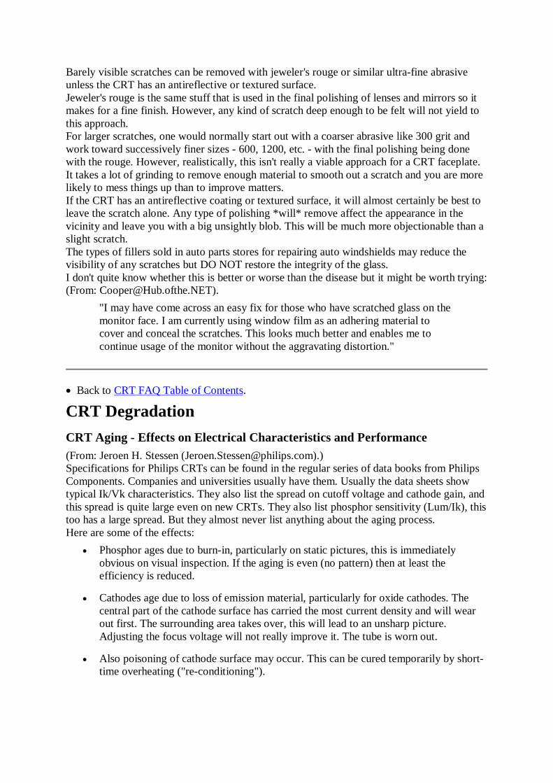
Barely visible scratches can be removed with jeweler's rouge or similar ultra-fine abrasiveunless the CRT has an antireflective or textured surface.Jeweler's rouge is the same stuff that is used in the final polishing of lenses and mirrors so itmakes for a fine finish. However, any kind of scratch deep enough to be felt will not yield tothis approach.For larger scratches, one would normally start out with a coarser abrasive like 300 grit andwork toward successively finer sizes - 600, 1200, etc. - with the final polishing being donewith the rouge. However, realistically, this isn't really a viable approach for a CRT faceplate.It takes a lot of grinding to remove enough material to smooth out a scratch and you are morelikely to mess things up than to improve matters.If the CRT has an antireflective coating or textured surface, it will almost certainly be best toleave the scratch alone. Any type of polishing *will* remove affect the appearance in thevicinity and leave you with a big unsightly blob. This will be much more objectionable than aslight scratch.The types of fillers sold in auto parts stores for repairing auto windshields may reduce thevisibility of any scratches but DO NOT restore the integrity of the glass.I don't quite know whether this is better or worse than the disease but it might be worth trying:(From: [email protected]).
"I may have come across an easy fix for those who have scratched glass on themonitor face. I am currently using window film as an adhering material tocover and conceal the scratches. This looks much better and enables me tocontinue usage of the monitor without the aggravating distortion."
• Back to CRT FAQ Table of Contents.
CRT Degradation
CRT Aging - Effects on Electrical Characteristics and Performance(From: Jeroen H. Stessen ([email protected]).)Specifications for Philips CRTs can be found in the regular series of data books from PhilipsComponents. Companies and universities usually have them. Usually the data sheets showtypical Ik/Vk characteristics. They also list the spread on cutoff voltage and cathode gain, andthis spread is quite large even on new CRTs. They also list phosphor sensitivity (Lum/Ik), thistoo has a large spread. But they almost never list anything about the aging process.Here are some of the effects:
• Phosphor ages due to burn-in, particularly on static pictures, this is immediatelyobvious on visual inspection. If the aging is even (no pattern) then at least theefficiency is reduced.
• Cathodes age due to loss of emission material, particularly for oxide cathodes. Thecentral part of the cathode surface has carried the most current density and will wearout first. The surrounding area takes over, this will lead to an unsharp picture.Adjusting the focus voltage will not really improve it. The tube is worn out.
• Also poisoning of cathode surface may occur. This can be cured temporarily by short-time overheating ("re-conditioning").

• The cathode that wears out first (often the red one) also loses gain, so the white pointof the image will shift (to cyan). The white point can be re-adjusted with the gainpotentiometers and the contrast, but peak brightness will not be as high as new.
• The cutoff voltages of all cathodes will drift. Common drift is adjusted by the user bycontrolling the brightness. Different drift leads to a coloration of the black backgroundlevel. In extreme cases vertical flyback lines will appear. Cutoff voltage can beadjusted with potentiometers, or there is automatic stabilisation. Still, the VG2(screen) may need periodic adjustment too.
• Leakage currents may disturb VG2 and focus voltage, re-adjustment has only atemporary effect.
• VG2 and focus potentiometers may wear out due to electromigration etc. A hole mayform under the wiper, re-adjustment is then impossible.
• Some types of cathode wear (according to a friend in Philips Semiconductors) cancause the Ik/Vk transfer characteristic to divert so much from an ideal gamma functionthat no adjustment can compensate for it. Then the tube is really worn out.
I hope that this helps you to distinguish between a really worn out tube and one that still hassome life in it after re-adjustment.
CRT Age Resulting in Dark PictureWhere circuit problems have been ruled out:(From: Jeroen Stessen ([email protected]).)Most probably the cathodes have worn out. The emission material on the surface slowlybecomes inactive. Usually you see one colour go first, then the others. At the same time youwill observe a loss in sharpness, because a larger cathode area is being used, giving a biggerspot.Rejuvenating is done by applying a (too) high filament voltage, in order to bring newemission material to the surface. It will not work for long and there is the risk of burning thefilament wire for good. It may be worth a try, though.Other wear mechanisms are:
• Glass browning (generally only for projection tubes).
• Phosphor aging (life time is defined by efficiency < 50%).
• Vacuum leaks (generally cause EHT flashover, audible).
Then again, it may also be that for some mysterious reason your VG2 voltage has droppedbelow spec. A too high VG2 voltage will cause a smaller cathode area to be used, leading to asharper picture but accelerated cathode wear.
Brightening an Old CRTIf performing adjustments of the internal background and/or screen controls still results in adark picture even after a long warmup period (and the controls are having an effect - they arenot faulty), the CRT may simply be near the end of its useful life. In the old days of TVs withshort lived CRTs, the CRT brightener was a common item (sold in every corner drugstore, itseemed!).First confirm that the filaments are running at the correct voltage - there could be a marginalconnection or bad resistor or capacitor in the filament power supply. Since this is usuallyderived from the flyback, it may not be possible to measure the (pulsed high frequency)

voltage with a DMM but a service manual will probably have a waveform or other test. Avisual examination is not a bad way to determine if the filaments are hot enough. They shouldbe a fairly bright orange to yellow color. A dim red or almost dark filament is probably notgetting its quota of electrons. It is not be the CRT since all three filaments are wired inparallel and for all three to be defective is very unlikely.If possible, confirm that the video output levels are correct. For cathode driven CRTs, toohigh a bias voltage will result in a darker than normal picture.CRT brighteners are available from parts suppliers like MCM Electronics. Some of these aredesigned as isolation transformers as well to deal with heater-to-cathode shorts.You can try a making a brightener. Caution: this may shorten the life of the CRT - possiblyquite dramatically (like it will blow in a couple of seconds or minutes). However, if themonitor or TV is otherwise destined for the scrap heap, it is worth a try.The approach is simple: you are going to increase the voltage to the filaments of the electronguns making them run hotter. Hopefully, just hotter enough to increase the brightness withoutblowing them out.Voltage for the CRT filament is usually obtained from a couple of turns on the flybacktransformer. Adding an extra turn will increase the voltage and thus the current making thefilaments run hotter. This will also shorten the CRT life - perhaps rather drastically. However,if the monitor was headed for the dumpster anyhow, you have nothing to lose. You can justadd a turn to an existing winding or make your own separate filament winding as outlined inthe section: Providing Isolation for a CRT H-K short.In some monitors, there is a separate filament supply on the mainboard - this should beobvious once you trace the filament wires from the video driver board). In this case, it stillmay be possible to increase this output or substitute another supply but a schematic will berequired.There are also commercial CRT rejuvenators that supposedly zap the cathodes of the electronguns. A TV or monitor service center may be able to provide this service, though it is, at best,a short term fix.
Checking the Age of the CRTSo you have this great deal on a used TV or monitor. How can you tell if the picture tube isabout to die on you?(From: Andy Cuffe ([email protected]).)The best way to tell is to look at the picture quality. There is no way to tell the exact numberof hours. Also, the life of CRTs varies quite a bit. some will go down hill much faster thanothers.
• It should be sharply focused over the entire screen and all 3 colors should be equallysharp.
• Set the picture brightness and color to maximum. If you see any bleeding or smearingto the right of bright objects don't buy it.
• When you first turn it on the picture should look normal in well under a minute. If it isdim, tinted, or blurry for more than a minute or two the CRT is getting weak.
• A B/W picture should not be tinted.
• The picture should have decent brightness with the picture at about mid range.
Apart form that, if the overall picture is good the CRT is fine. CRTs usually fail very slowly.Even if it's starting to show it's age it probably has several years left.(Portions from: Jerry G. ([email protected]).)

You cannot tell the hours used by just looking or even measuring a tube. A tube can go at anytime. There are no hour counters!Turn on the unit and see if there is any unusual bleeding of the image in the picture at highcontrast levels. When turning the brightness up and down, the color temperature should notchange, only the brightness. When turning the contrast up and down, the focus at the centershould also be very stable. It may change only a little bit. When turning on the set, the colortemperature should be stable within about 3 to 5 minutes.Look at the colors in the corners to see if the purity is good. Bad purity can be attributed to amiss-adjusted yoke assembly, to a bad shadow mask.To know the manufacture date of the unit, it us usually on the back with the model and serialnumber. Most TV sets are on about 5 to 8 hours a day if it is a family TV. If it is a bedroomTV the hours may be 1/2 that amount. Monitors may be on 24 hours a day - or much less.A good way to know if the emission of the CRT is up to specs is to get a CRT analyzer andmeasure the gun emission. Some service centers own one.
• Back to CRT FAQ Table of Contents.
CRT Rejuvenation
What is CRT Rejuvenation?Where one or more electron guns in the CRT have deteriorated due to wear and tear, it issometimes possible to give them a new, but possibly, temporary lease on life throughrejuvenation using a special piece of CRT service equipment.There may be some schematics for commercial CRT rejuvenators accessible from the SencoreService Page.(From: Gary Klechowitz ([email protected]).)When I rejuvenate a tube I inform the customer that there is no warranty on the job.Rejuvenating a CRT is like when Clatuu was brought back to life by Gort in "The Day TheEarth Stood Still". When asked "How long will you live"? he replied: "no one knows".I use a Sencore Beam Builder. If your tube is just moderately dim and blurry but still showsgood cut off threshold, I would just use the auto restore mode on the beam builder rather thanusing the restore button. If the tube is really bad with little or no cutoff threshold, then therejuvenator is needed but that has less than a 50% chance of fixing the tube and in many casesthe tube gets worse to trashed in the process.
CRT Degradation and Rejuvenation
"As I understand it, when a CRT ages, its filament looses material. It ejectsfewer electrons, and this accounts for the need to crank up the cutoff. Is thefocusing problem caused by the high cutoff voltage accelerating the electronstoo fast for the focusing assembly to work? And what would explain theshadowing problem?"
Replies from: Jeroen H. Stessen ([email protected]) and another engineer atPhilips who we shall call Tom.Tom:Yes, the cathode surface is losing the Barium/Strontium oxide slowly and hence the workingvoltage to free the electrons is rising. In itself, this will not change the cut-off voltage neededfor proper operation. This stays the same, only there are fewer electrons left that can be drawntowards the screen at a certain drive voltage. The focusing problem occurs at the moment thatthe TV-set tries to establish a certain beam current and finds out that a higher driver voltage is

needed to give this current. Consequently, a larger cathode area is used to get enoughelectrons out of it. This larger cathode area will be imaged onto the screen and give a largerspot size.Another point is the drift of leakage current, leading in a practical TV-set with highimpedance focus circuit (this allows voltage drop) to a focus voltage at the CRT focus pin thatis lower than it should be and this again leads to a bad focus performance.Jeroen:Readjustment of the focus voltage will be only a temporary solution.Addressing each of the effects and CRT rejuvenation:
1. Why is poor focus sometimes a symptom of a failing CRT?Tom:Normally only the emission from the centre of the cathode adds to the electron beam. If theemission material in the centre is exhausted then the outer area comes in. This is a largersurface, the electron lens projects this into a larger spot. It is not that the focus is bad, the lensworks OK. It is that a larger object is projected onto a larger image.Jeroen:This applies mainly to oxide cathodes. Impregnated cathodes are much more robust. They canbe applied at a higher cutoff voltage and thus deliver a smaller spot without premature wear.They are more sensitive to a too high heater temperature, however, because they are operatedat a higher temperature to begin with. They do evaporate more metal during their lifetime. Atone time there was fear that they would deposit too much metal on the glass around theelectrodes, leading to leakage currents. These can cause drift of focus and screen voltages andcan disturb the cutoff current measurement. Those can influence the picture too.Tom:Impregnated cathodes contain a lot of emission material that moves more easily towards thecathode surface as time passes. Oxide cathodes have the problem that the Ba/Sr-oxide ispositioned too deep to be very effective. Hence, the life time of an I-cathode should be longerthan that of an oxide cathode but indeed the sensitivity to correct heater voltage is higher.Second, an impregnated cathode, being highly conductive compared to an oxide cathodewhich is a semi-conductor, can handle a much higher peak current since the cathode materialis not locally heated up by this peak current. An oxide cathode can be destroyed by a too highpeak beam current !Jeroen:Oxide cathodes are typically operated at cutoff voltages between 100 and 130 V. Impregnatedcathodes are typically operated at cutoff voltages between 130 V and 200 V. Hence they canprovide a much sharper spot, but it is also much more difficult to design a video outputamplifier with sufficient bandwidth at the required large drive voltage (like 120 V peak-peak).
2. Why is horizontal streaking sometimes another symptom?Jeroen:Two symptoms, both related to the cutoff voltage being higher than what the video outputamplifier(s) can deliver. The cutoff voltage is proportional to the VG2 (second grid voltage).The higher VG2 is the higher the cutoff voltage VK - VG1 must be to blank the beam. Thevideo amplifier delivers VK. VG1 is fixed. Remember: cathode drive is negative, e.g. +130V= black, +30V = white.If the video amplifier clips before cutoff is reached then the beam will not be blankedcompletely and you will see a lighted background with slanted retrace lines. Some class-Bvideo amps will also show a bad recovery time from clipping to black, this may lead to blackstreaks after black images. Class-A amps should not have this problem. (In my experience thisis more common with clipping to white, usually leading to red or yellow streaks.)

If the cutoff voltage rises (due to some unexplained wear) or because VG2 rises (due to driftor due to owner intervention: turning the Screen potmeter) then the user may compensate forthe increased (background) brightness by lowering the brightness control of the set. Sometelevisions automatically lower the brightness of each channel because they have automaticcutoff control. Either way, the cathode voltages rise and clipping may occur with retrace linesas a result.Tom:Well, as said earlier, in principle the cut-off doesn't change due to cathode wear-out. Thefewer electrons still need the same voltage to prevent them from reaching the accelleratinglens. I have heard of cut- off drift due to distance drift between G1 and G2 for which it is verysensitive. However, this is not something that gets worse over time.
3. And finally, what is the real story on CRT restorers/rejuvenators?Jeroen:Some of the possible 'remedies' include:
• Excess heater temperature may bring some new emission material to the surface of thecathode. This is done by putting 9-10 V (?) on a 6.3 V heater. There is not emissionmaterial much left, so this will be a temporary solution at best. I don't think it isneeded or recommended with I-cathodes (impregnated).
Tom:This also helps for poisoned cathodes. Cathodes that have been operated too long on atoo low heater voltage get poisoned, meaning that the Ba/Sr-oxide gets chemicallybinded, leading to a higher working voltage. Indeed, only oxide cathodes can berejuvenated this way. Impregnated cathodes have a more sudden death mechanism andcan not be regenerated in this way.There is also the risk of burning out a heater filament for good.
• Some type of electrode shorts may be removed by high currents.
• The vacuum may be improved by activating the getter electrode using an inductionheater or RF source to heat the ring shaped getter electrode to red/orange temperature.(This probably only applies and then only in a limited way if the getter spot has faded- turned red or milky from its normal silvery appearance --- sam.)
Tom:
• Further: burning metal whiskers off the electrodes can help reducing a leakage currentproblem.
Jeroen:This is done by running high (flash) currents between electrodes. A similar procedureis performed on new picture tubes in the factory.
Also see the sections starting with: "Brightening an old CRT".
More Comments on CRT Rejuvenation(From: Ren Tescher ([email protected]).)Reduced emission (dim picture) can occur when the cathode/filament has used up most of theelectrons it can emit to the screen. Or, a 'crust' may have formed on the thoriated emittermaterial that can be 'boiled off' to expose more electrons.A rejuvenator or restorer generally hits the cathode/filament with a higher than normal currentto accomplish this.But, while a rejuvenator gives the cathode/filament a 'blast' of power, a restorer can slowlyincrease the temperature while monitoring beam current on one of the grids.

So generally a rejuvenator was a 'do or die' unit and a restorer could give only what wasneeded to accomplish increased emission. But these definitions have always been blurred byadvertising hype.The early restorers, such as my REM, had the operator watch the grid current on a meter(s) todetermine when emission was sufficient. I suppose newer units have a PIC chip or some otherlogic to do the job.(From: Terry DeWick ([email protected]).)I use a hand held Tesla coil to all pins for about 5 seconds. Then, follow up with rejuvenatorfor a quick check and cleanup if needed. Tesla coil is type the neon sign people use fortesting. 95% or better luck - saved a lot of out of warranty Zeniths from big repair bills orjunk pile.
Home-Made CRT Rejuvenator 1(From: Tony Duell ([email protected]).)I've read some articles in 'Television' which describe home-brew CRT rejuvenators. I've nottried any of the circuits yet...It appears that you overrun the heater by up to 50% (for a 6V heater, try 7.5V and 9V, say).Don't blame me if it burns out ;-)You then apply about 300V, current limited to say 50 or 60mA between cathode and 1st grid.One of the older designs used the UK 240V mains, a single diode as a half-wave rectifier, anda 15W light bulb in series for this PSU. I don't like unisolated equipment, so I'm not going totry it.Some designs apply that voltage continuously, and you watch the emission current rising (orthe bulb getting brighter...). With others you apply it for a few seconds, and then check theemission using, e.g. a 12V supply and a microammeter between cathode and grid.One old article suggested that if you get no improvement, switch off the heater supply withthe 300V still connected. As the cathode cools down, you get quite violent stripping of thecathode - observable as sparks from the electron gun area of the CRT. On the other hand, it isclaimed that this can completely ruin the cathode, or even cause short-circuits to occur in theCRT.
Home-Made CRT Rejuvenator 2I have no comments one way or another with respect to this device. Please contact the authorfor further information.(From: Mario Di Stefano ([email protected]).)Here is the 'gadget' I use to rejuvenate 'tired' CRT's:
T1 o---+--------+ +------------------------------- > | )||( M | )||( A | )||( 6.3 or 12 Vac To Filament I | )||( Secondary CRT Tube N | )||( (no Polarity) S | )||( | )||( o---|-----+--+ +------------------------------- > | | | ---------------------------------------- > CRT Cathode | | +-----+ _|_ -------------------| LP1 |-----o o------------ > CRT 1st Grid +-----+ P1

Where:
• T1 is a standard mains AC transformer.
• LP1 is a standard FILAMENT LAMP (60 - 100 W) working voltage according tomains.
• P1 Hand Pushbutton.
Other things needed (not shown):
• Mains switch (best if with overload protection or with fuse)
• 4 ISOLATED clips like the ones used in electronics to make contacts with the pins ofICs. These isolated clips ARE IMPORTANT. You don't have to touch any connectionduring the cleaning.
I think this circuit works better if the mains voltage is 220 Vac.How to use it:First we have an tired CRT (BW or colour is the same). We have poor image contrast,'strange' brightness, also strange colours. Next we have to remove (if present) the CRT socketto its circuitry (beware to disconnect mains voltage FIRST!!!!!). At this point could be usefulto discharge the HV using an isolated wire FIRST connected to CRT grey body and then tothe make the contact UNDER the suction gummy which carries EHT. to the tube. It is not adangerous voltage, but could be better not to discharge it over the body!Now we have to identify the filament pins. Usually on the schematic circuitry of theMonitor/TV it is clearly written. If the schematic is not available, using an ohmmeter weshould find the two contacts which gives a few ohms. These contacts usually are put asideeach other) have to be connected to the transformer secondary of the circuit above. TheCathode and 1st grids can be found looking very closely into the tube glass (use lens and goodlight if necessary). Keep in mind the way the CRT electron sources are built. These usuallyfollows this:
Cathode | (B/W CRT tub e) V O------+ | | + | | <- 1st Grid Filament + | | + |**| <-Spark (read text below) O------+ | | | | | | Cathode O---------+ | Connection | | 1st Grid O------------+ (Damn'd A SCII graphics!) Connection
Try to connect and turn on the transformer. The Filament in the CRT should turn on in a not-so-bright red (if it is a colour tube, we have 3 filaments on).Now turn off the transformer again. Connect the Cathode wire to the cathode pin of the CRTTube. Connect the 1st grid accordingly.Turn on the transformer. FIRE button P1. If there is dust (due to aging) between the cathodeand 1st grid, the circuit will blow-up it. If this happens, you could (but not always) even seethe LP1 turn on and off randomly (a good cleaning gives a lamp OFF) and some sparks insidethe tube. The tube collar glass now becomes hot: it is normal. You can even 'force' better

sparks if you 'ting' your finger against the CRT glass (not so strong, of course). If it is aColour CRT, you have 3 Cathodes, 3 1st grids a anyway 1 filament. Useless to say that theprocedure have to be carried out for all these electrodes. A good cleaning, gives a LP1 steadyOFF. If it is a steady bright or dim, means that a 'bridge' has been formed between theelectrodes and there is no way to recover the tube. Turn off the mains, remove theconnections, and re-apply the original socket. That's all. I'm not tired to say: BEWARE OFTHE MAINS VOLTAGE: IT CAN KILL!! If you are not so skilled, don't try to do thisprocedure. I used this circuit lots of times. It worked almost anyway. I recovered lot of thrownaway PC monitors, and now are working well....
Home-Made CRT Rejuvenator 3Here's another circuit found on the Web:
• CRT Rejuvenator Description
• CRT Rejuvenator Schematic
And, some comments:(From: Chris F.I recently built a homemade CRT tester & rejuvenator from plans I got these plans. The testmode works quite well, providing a good indication of the CRT emissions and showing thepresence of H-K or K-G shorts. But the restore mode often doesn't help very much, though ithas done a half-decent job on at least a few old CRTs. Anyway, I've been told that Sencores"Beam Builder" applies 450 Volts cathode to grid for a short time to restore the emissions.Now I have some old 450-volt transformers from really old TVs and I wondered if I couldmodify this design to use 450 VAC between cathode and grid (during restoration only). Howlong would the restoration process take at this voltage, would this work, and how dangerouswould it be? I've heard horror stories of all kinds about CRTs during handling, rejuvenation,and so on, and I don't like taking chances with these things.But I'd rather give this a try than spend the $2000 Cdn it would cost me for a Sencore unit.
• Back to CRT FAQ Table of Contents.
Items of Interest
Lifespans of Monitors(From: Bob Myers ([email protected]).)Most manufacturers will quote an MTBF (Mean Time Before Failure) of somewhere in the30,000 to 60,000 hour range, EXCLUSIVE OF the CRT. The typical CRT, without anextended-life cathode, is usually good for 10,000 to 15,000 hours before it reaches half of itsinitial brightness. Note that, if you leave your monitor on all the time, a year is just about8,000 hours.The only 'tune-up that a monitor should need, exclusive of adjustments needed followingreplacement of a failed component, would be video amplifier and/or CRT biasing adjustmentsto compensate for the aging of the tube. These are usually done only if you're using the thingin an application where exact color/brightness matching is important. Regular degaussing ofthe unit may be needed, of course, but I'm not considering that a tune-up or adjustment.
Monitor Life, Energy Conservation, and Laziness

A common misconception about the care and feeding of computer monitors is that theyshould be left on all the time. While there are some advantages to this, there are many moredisadvantages:
1. CRT Life: The life of a monitor is determined by the life of the CRT. The CRT is byfar the most expensive single part and it is usually not worth repairing a monitor inwhich the CRT requires replacement. The brightness half-life of a CRT is usuallyabout 10-15 K hours of on time independent of what is being displayed on the screen.10 K hours is only a little more than a year. By not turning the monitor off at night,you are reducing the life of the monitor by a factor of 2-3. Screen savers do not makeany substantial difference especially with modern displays using X-Windows or MSWindows where the screen layout is not fixed. With video display terminals, the textalways came up in the same position and eventually burned impressions into thescreen phosphor. With modern CRTs, the filaments can be left to minimize the timeneeded for a picture to appear since this doesn't affect CRT life very much.
2. Component life: The heat generated inside a monitor tends to dry out parts likeelectrolytic capacitors thus shortening their life. These effects are particularly severe atnight during the summer when the air conditioning may be off but it is still aconsideration year around.
3. Safety: While electronic equipment designed and manufactured in accordance with theNational Electrical Codes is very safe, there is always a small risk of catastrophicfailure resulting in a fire. With no one around, even with sprinklers and smoke alarms,such an failure could be much more disastrous.
4. Energy use: While modern monitors use a lot less energy than their older cousins, theaggregate energy usage is not something to be ignored. A typical monitor usesbetween 60 and 200 Watts. Thus at a $.10 per kWH electric rate such a monitor willcost between $48 and $160 a year for electricity. During the night, 1/2 to 2/3 of this iswasted for every monitor that is left on. If air conditioning is on during the night, thenthere is the additional energy usage needed to remove this heat as well - probablyabout half the cost of the electricity to run the monitor.
The popular rationalization for what is most often just laziness is that power-on is a stressfultime for any electronic device and reducing the number of power cycles will prolong the lifeof the monitor. With a properly designed monitor, this is rarely an issue. Can you recall thelast time a monitor blew up when it was turned on? The other argument, which has more basisin reality is that the thermal cycling resulting from turning a monitor on and off will shortenits life. It is true that such thermal stress can contribute to various kinds of failures due to badsolder connections. However, these can be easily repaired and do not effect the monitor'sheart - the CRT. You wouldn't leave your TV on 24 hours a day, would you? Full powersaving where virtually everything including the CRT filaments is turned off is really best butthe delay before a picture appears may be 20 seconds or more.Also see the section: Thernal Cycling and Component Life.Some of the newest ('green') monitors have energy conserving capabilities. However, it isnecessary for the software to trigger these power reduction or power down modes. Fewmonitors in actual use and fewer workstations or PCs are set up to support these features. Ifyou have such a monitor and computer to support it, by all means set up the necessary poweroff/power down timers. However, using the power saving modes of a 'green' PC with an oldermonitor can potentially cause damage since some of the modes disable the sync signals. A

'green' monitor which can detect a blank screen and and use this as a trigger can easily be usedwith a screen saver which can be set to display a blank screen - on any PC or workstation.Even if the monitor does not support power saving modes, a blank screen or dark picture willreduce stress on the CRT and power supply. Electronic components will run cooler and lastlonger.Please make it a habit to turn your monitors off at night. This will extend the life of themonitor (and your investment) and is good for the environment as well. For workstations,there are good reasons to leave the system unit on all the time. However, the monitor shouldbe turned off using its power switch. For PCs, my recommendation is that the entire unit beturned off at night since the boot process is very quick and PCs are generally not required tobe accessible over a network 24 hours a day.
Thernal Cycling and Component Life(From: Bob Myers ([email protected]).)In a CRT monitor, the shortest-lived component BY FAR is the CRT itself, and it ages (moreproperly, the cathode is aging) as long as the heater is on and the tube is under bias. Mostmonitors don't get around to turning the heater down or off until they enter the DPMS"suspend" or "off" modes. (And no, screen-savers do NOT help here - the tube is still on andthe cathode is aging.)Other factors - simply having the circuits hot and powered up in general means that they'reaging. Clearly, they're NOT aging when they're off. This needs to be balanced against thethermal-cycling sort of stresses that you mention which happen during power cycling, and thisis why I recommend shutting off only when you're going to be away for an extended period,such as overnight. This is, of course, most important for those components which have clearheat-related aging, but most do to some extent. Esp. vulnerable are things like electrolyticcaps, for obvious reasons.The bottom line is that nothing is ever going to last forever, and trying to maximize the life ofthe product is an exercise in making tradeoffs between various aging/failure mechanisms.
Expected Life of TV CRTs(From: David ([email protected]).)The "unofficial" designed life is 10,000 hours on the guns used in most Thomsonmanufactured sets. I got this from a Thomson engineer. They are no longer plating the gunsbut dipping them.Given the number of hours most people watch TV these days, take 6 hours a day on average365 days a year and you get 4.5 years. Also note that the 10,000 hours is at the preset way toohigh brightness and contrast settings that the set comes with from the factory. Since mostpeople never adjust from these expect 5 years. We do the contract repair service for all thehospitals and hotels in our area. The sets bought in 1993 in one hospital are now coming inwith complaint of green picture or bad focus at edges. All due to the picture tubes being wornout.Zenith on the other hand has a company expected life of 3 years on new sets. Plus the hardshort failures they have been having on all "L" and "M" line sets.Thomson does have a "better" line of picture tubes for the higher end sets. They are actuallyplating the guns the way they use to.Final note: we see 7 and 8 year old sets come in all the time with crappy picture tubes, and afew with really good looking pictures.
Why are Prices of Video Monitors So High Compared to Similarly Size TVs?How come I can buy a 32" Sony Trinitron TV set for $800, but when it comes to buying amonitor for my PC, $1400 only gets me a no-name 20" tube?

Why can't a giant like Sony produce a PC monitor anywhere close in cost to an equivalentlysized TV set?(Some of this from: Mike Stewart ([email protected]).)There are several significant factors being overlooked here:
1. Economy of scale. There are still *many* more TV sets being sold than computermonitors. Manufacturers order TV chipsets in much larger quantities. This drivesdown the price.
2. Resolution. NTSC TV signals aren't even VGA resolution. Try getting that 32" SonyTrinitron XBR to give you 1280x1024. A computer monitor has a CRT with aresolution about 2 to 3 times that of a TV of similar size in both horizontal and verticaldirections. The beam is also more sharply focused.
3. Refresh rates. NTSC TV signals come at one refresh rate, period. You either watchbroadcast NTSC at 59.94Hz (interlaced), or you don't watch it at all. No nice, clean72Hz NI display on there. (NOTE: This only refers to the 99+% of TV playbackequipment that contains no line- doubling circuitry. That's fair, as you'll pay a good bitmore for a non-interlaced, line-doubled NTSC picture than the previous poster wascomplaining about, anyway.)
Therefore, a auto-scan monitor needs more sophisticated deflection and power supplycircuitry. It must run at much higher scan rates and this complicates the circuitry aswell.
4. Geometry. The precision of a good computer monitor is much greater then any TV.The sides will be parallel and square. Adjustments are provided to eliminatepincushion, keystone, and trapizoid distortions.
5. Stability. The image on a high quality computer monitor is rock solid and does notshift position or change size as components warm up, or the power line voltagefluctuates, etc.
Problems with Designing a Combination TV and Computer Monitor(The following is from: Bob Myers ([email protected]).)It's possible, and has been done (for instance, Toshiba has one product and offerings fromother companies are available or are on the way). But such designs ARE compromises, andwon't give the best performance possible in either application.There is a fundamental difference between CRTs designed for TV use, and those used incomputer monitors. It's a brightness/resolution tradeoff - TV tubes are run about 3X or so thebrightness of a typical computer monitor, but sacrifice the ability to use small spot sizes andfine dot pitches to do this. You don't see very many color tubes running at 100 - 150 fLbrightness and still using an 0.28 mm pitch!
Picture Tube Disassembly for Demonstration PurposesHere are several questions from a budding exhibit constructor:
"1. I am interested in using a dead CRT for a display at our science center onhow things work and know about the safety issues. Also, I would really like tocut one (or parts of one) open, so it would be great to know what other thingsto worry about or what tools to use."
(Portions from: Jeroen H. Stessen ([email protected]).)Back in the TV-lab we have an unassembled picture tube for that purpose. Most convenient!

• First, make sure that the electrical capacitance of the CRT is properly discharged. Pullthe mains plug. Connect a wire to the outer aquadag. Then push it under the anode capand make a good short-circuit. Remove the anode cap and EHT wire.
• Next you want to break the vacuum. This is my preferred method:
o Use a sharp object or a drill to punch a small hole in the anode contact. It'smade of really soft metal, probably copper. It takes several minutes for the airto fill the entire tube. In the mean time you can have some fun putting yourfinger over the hole. No, that's not harmful.
o The other way to break the vacuum is via the thin tube that was used to pumpthe air out of the tube. That is located in the middle of the socket at the end ofthe neck. Remove the plastic part around the pins and break the little tube byhitting it with e.g. the tip of a screwdriver (+hammer). If you score it with afine triangular file, it will crack off cleanly.
I like this method less, for fear of breaking too much glass.
• You might also want to cut off the neck for easier manipulation and study of theelectron gun parts. Use a glass cutting saw if one is available. Else, score totallyaround the neck with a fine triangular file or glass cutter and then it should snap fairlycleanly.
Don't just chop off the neck - especially if you have not released the vacuum. Asidefrom the danger of flying bits of glass, you get a very characteristic dirty spot on thefront of the screen, it looks as if the phosphor layer has been blown away from thefaceplate by the strong inrush of air. Or maybe it was the shadow mask being blownagainst the faceplate. Very tell-tale and spoils your nice display.
• The deflection coils (and purity/convergence magnet assembly, if used) are also easilyremoved. Loosen the clamps and twist and slide them off of the neck. It's best to findan old tube where the coils have not been potted (against the noise they tend to make).Then you can see them very well.
• The difficult part will be to cut the connection between faceplate and funnel. Normallythe two parts are glued together. I think it will require a glass cutting saw to get thetube open again.
You want to separate it just behind the faceplate or else there will not be enough spaceto grab and remove the shadow mask. That's just clicked into place, very easy tounclick.
And one more question:
"2. I would assume the phosphors are a problem... Any things I need to knowabout chemical hazards?"
Old tubes had environmentally unfriendly phosphors, containing heavy metals such ascadmium and some rare earths. Nothing immediately toxic but the long-term effects are nothealthy either. Modern tubes should at least have cadmium-free phosphor. But the phosphor iscovered with a metal layer, so normally it would not even be exposed. Just don't touch it.
"3. Or that we would need to bond a cover over the exposed interiorcomponents both for safety and to keep them intact?"
Obviously, you will want to prevent the curious from being injured by sharp metal parts butnothing will fall apart (assuming your original disassembly was not overly violent). The

internal magnetic screen is attached to the shadow mask, which is clicked into metal parts atthe face plate. The whole assembly removes easily.Have fun, this is going to be a wonderful demonstration of a very practical application ofsome heavy *physics*.
Turning a Large CRT Faceplate into the Side of a Fish TankSo, you want to turn your 1950's vintage console TV into the ultimate fish tank experience.WARNING: Make sure the CRT capacitance had been discharged and the vacuum let outfirst! See the section: Disposing of Dead TVs or Monitors (CRTs and Charged HVCapacitors).Cutting the CRT apart would be a tricky business. If it is a typical color TV, the front is overan inch thick so you have to slice it around the edge behind the main faceplate. I wouldn'trecommend even trying a glass cutter except as a last resort. If you can gain access to adiamond saw to cut around the edge, that is possible - a masonry dealer or industrial glasscompany might be talked into doing this. With the proper tools, it is a 10 minute job. Theproblem then becomes whether the inside surface is frosted or not. The phosphors may be atleast somewhat toxic (to fish at least) so every trace of them need to be removed. Once this isdone, the resulting finish (if the glass itself is frosted) may interfere with your fish viewingpleasure. :-)
Why do TVs Overscan?(The following includes material from: Jeroen Stessen ([email protected]).)TVs are always set up to generate a picture which is 10-15 percent large than the visible faceof the CRT. Why?In the early days of TV, this was probably done to make the design easier. Componenttolerances and power line voltage fluctuations would be masked even if they caused changesin picture size.There certainly is almost no reason today to have any more than a couple of percent overscan.Most modern TVs have very well regulated power supplies and component values do notreally drift much.Computer monitors, for example, are usually set up for no overscan at all so that the entireimage is visible.We are constantly reminded of that, now that we are building TV's with VGA inputs(PD5029C1 in the USA, US$ 2000). This mixed application has overscan in TV mode andunderscan in VGA mode. Geometry adjustment is quite critical if you see border-on-border.Unfortunately, TV's may be good but VCR's certainly are not. If you have too little overscanand then put the VCR in any feature mode (like picture search) then one (black) picture edgemay become visible. Bad form. Viewers do not like this.While design considerations may have been the original reason for overscan, now it hasbecome accepted as a de facto standard, and broadcasters are counting on the overscan beinga certain percentage. One wonders whether it will ever change or whether this really matters.I suppose when we have true flat panel digitally addressed displays, we might have 0%overscan.At the Japan Electronics Show all the signs are pointed toward flat panel displays so maybe Iwill not have to hold your breath for much longer.Physically, as with an LCD display on a laptop computer, there will be 0% overscan (no needto build the extra pixels) but that doesn't mean that all 480 lines will be visible.
What is Aquadag?You may see the term 'Aquadag' referring the the black paint covering the outside of most ofthe funnel section of the CRT.

(From: Nicholas Bodley ([email protected]).)Aquadag used to be a trademark of Acheson Colloids [Corp.?], I think around Niagara Fallsor Buffalo, NY. It was one of many "-dag" colloidal graphites; they also made Oildag, Gredag(grease), and Alcoholdag, as I recall. Unfortunately, it's probably sold in 55-gallon drumsminimum. I hope you can find smaller quantities. Are there any CRT rebuild shops around theUSA? See the Thomas Catalog (ThomCat) in a library to find Acheson.I am pretty sure there's nothing magic about the graphite. If you can find some reasonably-priced nickel-flake or copper-flake paint (be sure it's conductive!), you might have anaffordable (?) coating. How about plain metal foil, maybe even ordinary aluminum foil? Yousurely don't need current-carrying capacity; you would need a decent adhesive, though. Howto make sure you have continuity between pieces, I'm not so sure; shoot for really tight crimpsthat deform the metal and are gas-tight. (This might, however, be quite unnecessary.)
Why are Indirectly Heated Cathodes Used in CRTsHere are three reasons:
1. The cathode can be made of and/or coated with a material optimal for emittingelectrons without regard to its performance as a heater.
2. The separate cathode and filament can be electrically isolated so that the filamentvoltage and cathode drive signal, if any, do not interfere.
3. The cathode can have an optimal shape for the application. This would be particularlysignificant for CRTs. The spot on the screen is a reduced focused image of theeffective shape of the emitting portion of the cathode.
Frequency Response of CRTs(From: Jeroen Stessen ([email protected]).)The impedance of a gun is fairly high, with 50 to 100 V p-p swing and 1 to 5 mA p-p beamcurrent it is in the order of 10 to 100 K Ohm. Consequently, series inductance plays noimportant role but parallel capacitance does! In fact, the video amplifiers supply moreparasitic capacitive current than beam current!For a TV tube the total parasitic capacitance (CRT + socket + PCB + amplifier outputdevices) is at least 10 pF. Assuming a beam current of 5 mA p-p at 100 V p-p swing thenabove 800 kHz there will be more peak-peak capacitive current than beam current !The pull-up resistor in the typical class-A video amplifier also consumes current, about 12mA p-p for an 8.2 K Ohm resistor. Together with the beam current this shifts the dominantpole up to 2.7 MHz. Obviously there is a dominant pole well within the range of interest, evenfor TV.Better tubes may or may not have lower C but it is not very important. The dominant pole isfirst shifted to a higher frequency by using lower-value pull-up resistors in the videoamplifier. Of course this will increase dissipation losses.Then the dominant pole is compensated by a zero in the emitter circuit of the output transistor.There may be other compensation networks too, often with inductors. This is what allows abetter monitor chassis to achieve a higher bandwidth.Frequency compensation alone is not enough. Without a sufficiently low value for the pull-upresistor the NPN transistor will simply switch off during a rising edge and the edge will belimited by the R*C of the dominant pole alone. The compensation network is effectivelydecoupled from the output by the switched-off transistor. Remember that, boys and girls!Of course, class-B designs with active pull-up will improve much. But good wide-band high-voltage PNP transistors are still a bit hard to get.

Of course, spot size (sharpness of focus) is critical to allow a better CRT to achieve a sharperpicture! A better monitor needs both a better CRT (sharper beam) and better video amplifiers(higher bandwidth).
• Back to CRT FAQ Table of Contents.
CRT Service Information
How to Read CRT Part NumbersMore than you ever wanted to know (but still not that useful)!(From: Jeff Roberts ([email protected]).)The following information comes from the Sencore CR7000 ManualThe tube number is broken down in to 5 parts:
Example: M / 36 / KME / 20 / XXPart 1: Tube Type:
A or W = TV picture tube.M = Monitor tubes (differ in the size and pitch of the phosphor dots).P = Projection tube.D = Electrostatic deflection.
Part 2: Minimum viewable diagonal. Measurement is in cm. (1 inch = 2.54 cm).Part 3: Family Number - Tubes Within a particular family have specific mechanical andelectrical characteristics.
These letters are assigned alphabetically beginning with "AAA", followed by "AAB","AAC", etc.Tubes with the same sequence of letters are identical as far as their setup for theSencore CR7000.The letter sequences are grouped according to the country they are manufactured in.
Part 4: Member of Family - This one or two digit number specifies a particular memberwithin a family.
A different number is assigned to tubes within the same family that have differentneck diameters, for example. Single digit member #s = monochrome, double digitmembers = Color tubes.
Part 5: Phosphor Type.
Typical Color CRT PinoutIt is usually possible - with a little effort - to determine the pinout of a CRT from the markingsand circuit configuration on the CRT neck board and by visually following the base lead wiresinside the neck of the tube.Here is one pinout common in color TVs. Note that this tube socket includes integral sparkgaps and pin 12 doesn't actually go into the CRT.
Pin 1: FocusPin 2: NCPin 3: NCPin 4: NCPin 5: G1Pin 6: Green CathodePin 7: G2Pin 8: Red CathodePin 9: Filament

Pin 10: FilamentPin 11: Blue CathodePin 12: Sparkgap Ground
Here is another without sparkgaps in the socket:Pin 1: FocusPin 2: NCPin 3: Blue CathodePin 4: FilamentPin 5: FilamentPin 6: G1Pin 7: Red CahtodePin 8: G2Pin 9: Green Cathode
(There may actually be no pins present for those marked "NC" as well as a gap between thehighest numbered pin and pin 1.)
CRT Substitution
"I have an RCA TV model # f20700dg that has a bad crt #A51ABU14X what Iwould like to know is can I replace it with a #A51AGC14X."
(From: Tech 7 ([email protected]).)Perhaps you need to know why the #'s are different?The A is for the grade of the tube (AA is all new, B is rebuilt etc), the 51 is size in cm, theABU is gun type, the 14 is # of elements used (pins), and the X is for phosphor type. Since thegun type is different in your two tubes, I would not spend the time to sub the tube without firstcheck the voltages on the old one, get a schematic of set for new one, compare the parametersand then decide.
CRT Replacement Worth It?The sad fact is that even if you can obtain a new CRT you won't have the proper set up forgetting proper alignment and convergence. They generally use various permanent magnetglued to the perimeter of the yoke to set the geometry of the raster. It takes a special factoryjig to do this step or really great persistence and patience. However, if you have the time andwill resist punching a hole in the new CRT before you finish, by all means.Also, consider the cost of a new CRT may be more than half the cost of the monitor when itwas new.Replacing a monochrome CRT is a snap in comparison.A better (or at least less stressful) approach is to locate a monitor that died due to a circuitproblem and salvage the CRT including the yoke and all the other magical magnets and coils.(From: Andy Cuffe ([email protected]).)I have found that most 15" monitors use compatible CRTs. I just put the CRT from an oldGateway2000 with analog controls into a nice 2 year old monitor. As long as the yokes andCRT sockets are similar it should work fine. Don't try to swap the yokes or you will never getit converged.
Rebuilt CRTs(From: B. K. Richardson ([email protected]).)Try Hawkeye. They have been giving us good service for at least 15 years. Their rebuilds arecovered by warranty.
• Hawk-Eye Picture Tube Mfg., Inc.724 Scott Avenue, Des Moines, IA. 50309-5052

Phone: 515-288-8567Fax: 515-288-8568
Suppliers of standard & high resolution color and monochrome picture tubes.
What Does It Take to be a Picture Tube Rebuilder, Really?(From: Charles Godard ([email protected]).)Back in the late 50's A Tech friend of mine built a picture tube rebuilding plant from scratch.He made a living with it for a few years selling rebuilt b&w tubes. Everybody around said hesold the best rebuilt tubes that you could get. He said the secret was in the good vacuum pumpand that he used and the amount of time that he pumped down the tube.He always said that a tube could be made to last practically forever if you could get a highenough vacuum on it. The only real money he put into his plant was in the pump.A few years ago he retired and brought the whole thing down to my shop for storage. It was amarvel to behold. The cooker was an old upright deep freeze with a pyrex pie plate for awindow. The lathe where he welded the tube necks onto the tube was built of scraps of angleiron with a washing machine motor. The device that he used to cut the necks off of the tubewas a model railroad controller with a homemade foot pedal and a couple of whittled downbroomsticks with metal tips shaped so that you could easily fold the nichrome wire around thetube neck. He said it was the only transformer he could find, at the time, that would hold up toheat the wire hot enough to cut the neck off of the tube. It was very low voltage but wouldsupply hi current.He said he had the most trouble when designing the inductance heater but finally got it builtwith the help of a local genius who had built one of our local TV station's nearly from scratchback in the 50's.In addition to the tube plant, he also designed and got a patent on a cotton picker. I've got acopy of his patent on display in my shop. Some of us only half believed him for years, whenhe said he had the patent, but when he died, we searched the shop and found his patent papershidden away in a file cabinet of old Sams Photofacts.We found the contract where he sold the rights to build and market the picker for a $500 perpicker royalty. The guy he sold it to took the patent and went to a nearby state, borrowed$200,000 from the bank with the Patent as collateral then skipped the country. My friendnever got anything from his invention, and some of his design ideas were later stolen andincorporated into some one of the big name picker manufacture's products.Those old guys were something else. They could start with a few old scraps and buildsomething worthwhile and useful.Speaking of patent's, I've also seen the original patent for the hinges RCA used to hold up thetops on the old console stereo's. I made a service call a few years ago, and the guy's widowshowed me the patent and his original prototype hinges. The only thing is, they took the ideafrom the patent and redesigned it so they wouldn't have to pay our local guy for the hinges.RCA's redesign didn't work as well as his original, but was recognizable as his original withonly a couple of changes. RCA 'did him' about the same way they 'did' Philo Farnsworth.When I get a slack spell, I'll try the inductance heater to see if it still works. If it does, I try iton the tubes and let you know. I believe you called it a Tesla coil?
Shipping Damage: Why Monitors are Like Basketballs(From: Stephen Swann ([email protected]).)Monitors are more prone to shipping damage than most other computer components, and itdoesn't help that they typically pass through several people's hands (several stages ofshipping) before they get to you: factory -> distribution center -> vendor -> you.

And from what I've seen first hand of shipping practices (I put in a couple of months workingin a distribution warehouse during college), you can safely assume that each stage of shippingis roughly the equivalent of your monitor being dropped down a flight of stairs.You wouldn't *believe* the abuse that UPS and FedEx can subject packages to. In fact,putting a *FRAGILE* sign on the side of the box is about the equivalent of writing "KICKME" on it. I remember receiving packages marked "FRAGILE" where the (originally cubical)cardboard boxes had been smashed into shapeless cardboard "bags", and it took us 20 minutesto figure out what the contents of the box had originally been. ("What are all these shards?" "Ithink it was some kind of vase" "No, it was some kind of lamp." "Where's the bulb socket,then?" "How about this squashed piece of aluminum?" "Yeah, you're right, but where's thecord then?" etc). :-) Shipping guys would think nothing of dropping "fragile" boxes fromwaist-high onto a concrete floor - safe in the knowledge that the package had passed throughso many hands that the damage could never possibly be traced back to them. "Blameless isGuiltless" should be the motto of these folks.Basically, what I'm saying is that if 1 monitor in 3 arrives arrives in workable condition, youshould be surprised that even that one monitor survived.
• Back to CRT FAQ Table of Contents.-- end V1.92 --